- Table of Contents
-
- H3C G6 Servers Storage Controller User Guide-6W100
- 00-Preface
- 01-Storage controller overview
- 02-Storage controller features
- 03-Configuring a VROC SATA RAID controller
- 04-Configuring an NVMe VROC module
- 05-Configuring an LSI-9540 or 9560 storage controller
- 06-Configuring a P460, P2404 or P4408 storage controller
- 07-Configuring an LSI 9500 series storage controller
- 08-Configuring a RAID-MARVELL-SANTACRUZ-LP-2i storage controller
- 09-Configuring a RAID-MARVELL-M.2 storage controller
- 10-Appendix A Troubleshooting storage controllers
- 11-Appendix B RAID arrays and fault tolerance
- Related Documents
-
| Title | Size | Download |
|---|---|---|
| 10-Appendix A Troubleshooting storage controllers | 2.65 MB |
Appendix A Troubleshooting storage controllers
This section provides troubleshooting information for common issues with storage controllers.
Viewing storage controller models
1. Sign in to HDM. For information about logging in to HDM, see the firmware update guide for the server.
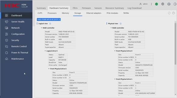
2. In the navigation pane, select Dashboard > Hardware Summary.
3. Click the Storage tab.
Figure 1 Viewing storage controller models
Drive failure
When the Fault/UID LED of a drive turns amber or the management tool shows that the drive is in Failed state, you can determine that the drive fails.
To solve this issue, perform one of the following tasks as needed:
· If the drive is not used for configuring a RAID array, replace the drive with a new one.
· If the failed drive is configured as a hot spare drive, replace the drive with a new one and configure the new drive as a hot spare drive.
· If the failed drive is a member of a non-redundant RAID array (for example, RAID 0 or simple volume), replace the failed drive with a new drive and reconfigure the RAID array.
· If the failed drive is a member of a redundant RAID array and is configured as a hot spare drive:
¡ If copyback is not enabled, replace the failed drive with a new drive and configure the new drive as a hot spare drive.
¡ If copyback is enabled, replace the failed the failed drive with a new drive.
· If the failed drive is a member of a redundant RAID array and is not configured as a hot spare drive, replace the failed drive with a new drive. Then, the RAID array will automatically rebuild the data.
Viewing the status of a physical or logical drive attached to a storage controller
Viewing the status of a physical drive
Viewing the status of a physical drive from HDM2
1. On the top navigation bar, click System.
2. In the left navigation pane, select Storage.
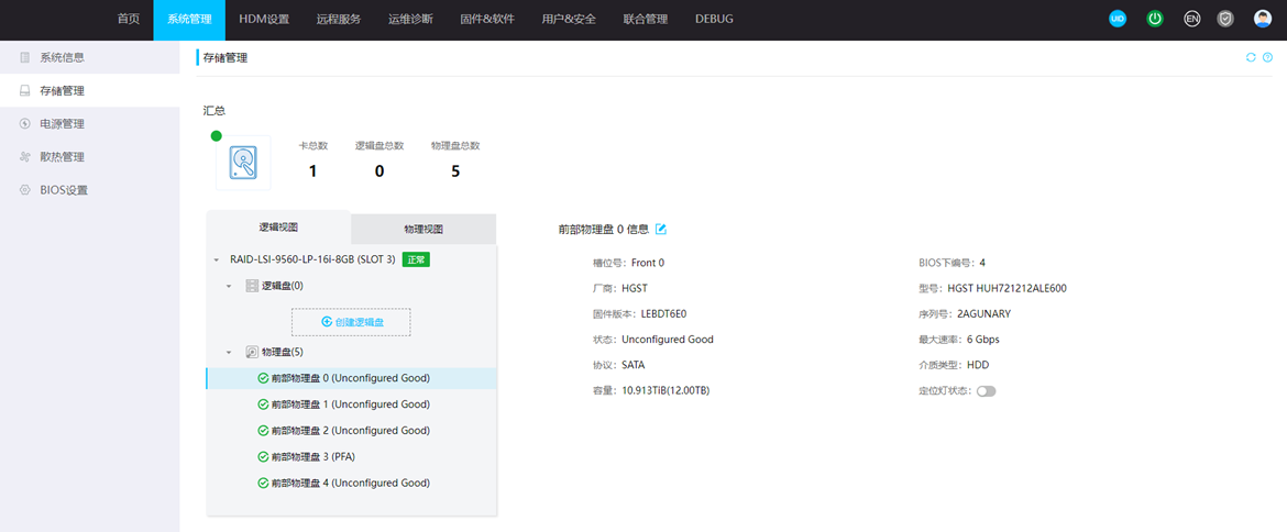
3. To view information about a physical drive:
a. On the Logical view tab, select a storage controller and a logical drive.
b. Select the physical drive.
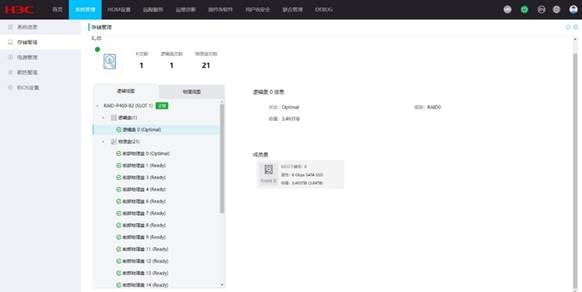
Figure 2 Viewing the status of a physical drive
Viewing the status of a physical drive attached to a PMC storage controller from BIOS
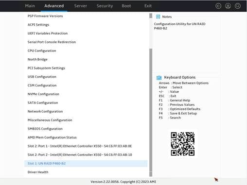
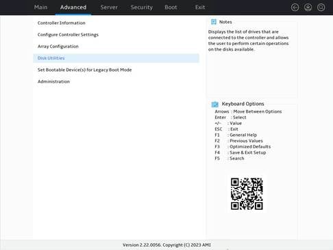
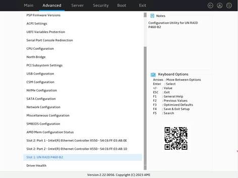
1. Click the Advanced tab, select the storage controller, and then press Enter.
Figure 3 Selecting the storage controller
2. Select Disk Utilities and then press Enter.
Figure 4 Selecting Disk Utilities
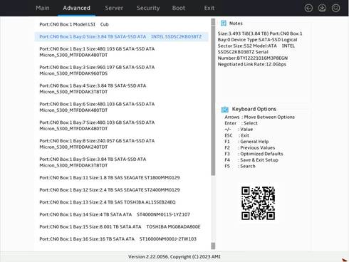
3. Select the target drive and then press Enter.
Figure 5 Selecting the target drive
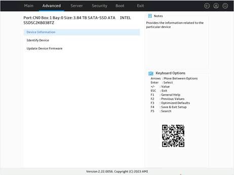
4. Select Device Information, and then press Enter.
Figure 6 Selecting Device Information
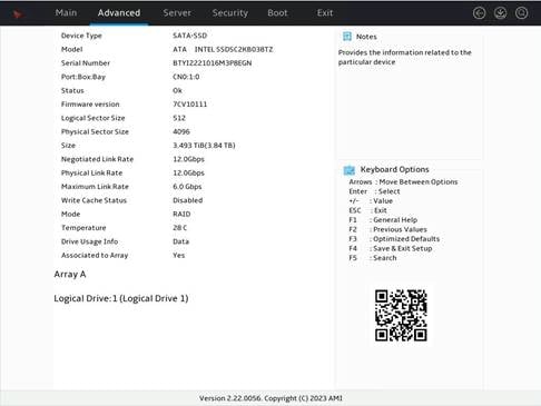
5. View the value of the Status field.
Figure 7 Viewing the value of the Status field
Viewing the status of a physical drive attached to an LSI storage controller from BIOS
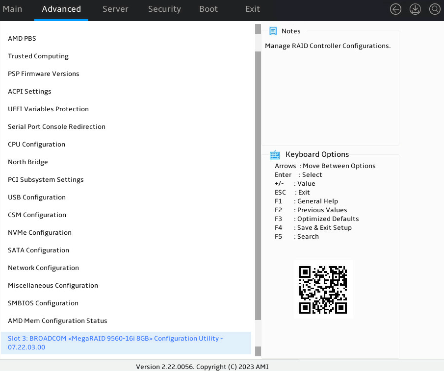
1. Click the Advanced tab, select the storage controller, and then press Enter.
Figure 8 Selecting the storage controller
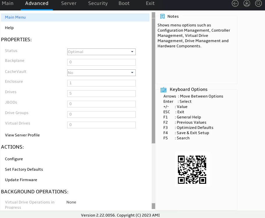
2. Select Main Menu and then press Enter.
Figure 9 Selecting Main Menu

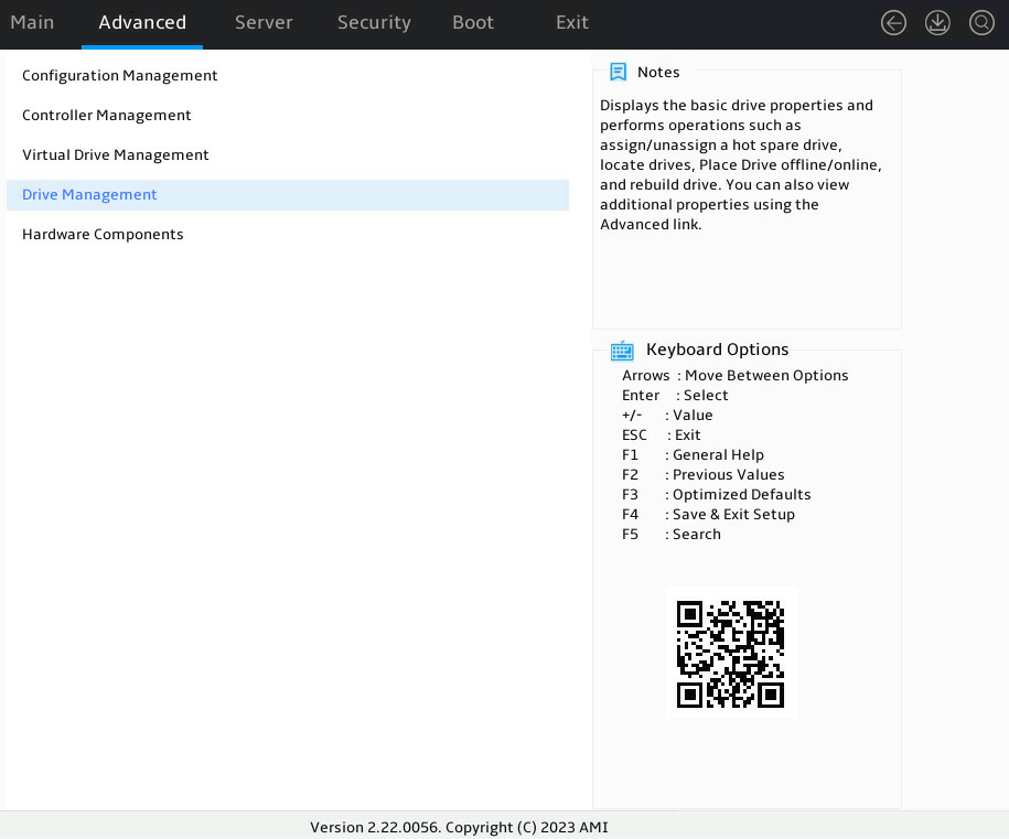
3. Select Drive Management, and then press Enter.
Figure 10 Selecting Drive Management
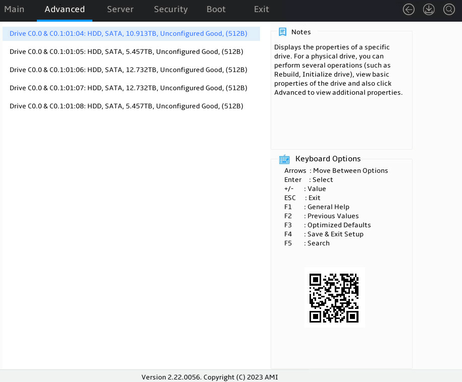
4. Select the target drive and then press Enter.
Figure 11 Select the target drive
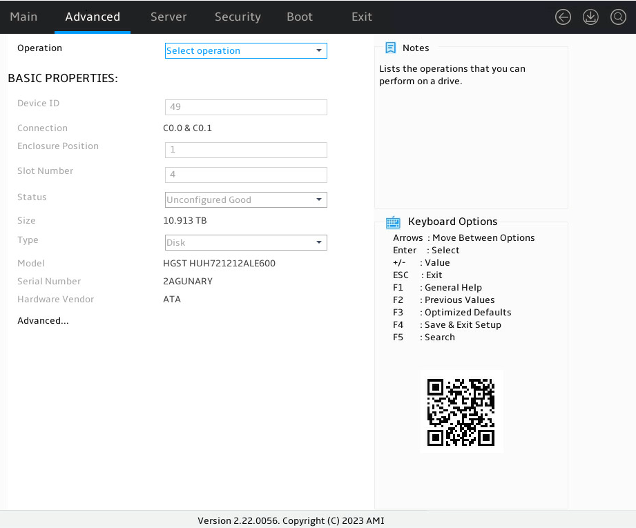
5. View the value of the Status field.
Figure 12 Viewing the value of the Status field
Physical drive status
Table 1 Physical drive status
|
Parameters |
Description |
|
Unconfigured Good |
The physical drive has been initialized or has not been configured, and it is available for RAID configuration and hot spare setting. |
|
Unconfigured Bad |
The physical drive is faulty or has residual RAID information. You need to replace to replace the faulty drive or manually delete residual RAID information. |
|
Online |
The physical drive is already used to create a RAID. |
|
Offline |
The physical drive is disabled. |
|
Rebuilding |
The physical drive is being used in RAID rebuilding. |
|
Hot Spare |
The physical drive is already used as a hot spare. |
|
Failed |
The physical drive failed. |
|
PFA |
The physical drive is analyzing possible failures. |
|
Raw |
A new physical drive or a physical drive in Unconfigured good state is uninitialized. |
|
Copyback |
Data is being copied from the hot spare drive back to the replacement drive of a failed drive. When this operation is complete, the hot spare returns to the hot standby state. |
|
Replacing |
Status of the hot spare drive when it is replacing the faulty member drive. |
Viewing the status of a logical drive
Viewing the status of a logical drive from HDM2
1. On the top navigation bar, click System.
2. In the left navigation pane, select Storage.
3. On the Logical view tab, select a logical drive to view its information.
Figure 13 Viewing the status of a logical drive from HDM2
Viewing the status of a logical drive attached to a PMC storage controller from BIOS
1. Click the Advanced tab, select the storage controller, and then press Enter.
Figure 14 Selecting the storage controller
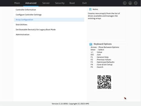
2. Select Array Configuration, and then press Enter.
Figure 15 Selecting Array Configuration
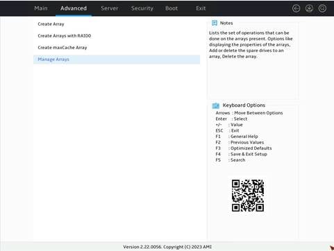
3. Select Manage Arrays, and then press Enter.
Figure 16 Selecting Manage Arrays
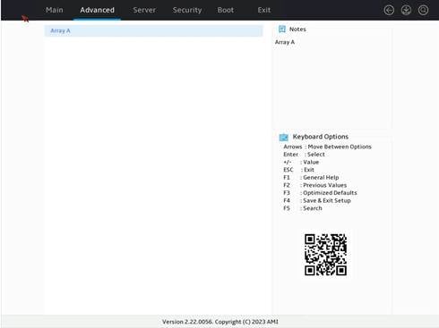
4. Select the array where the logical drive resides and then press Enter.
Figure 17 Selecting the array where the logical drive resides
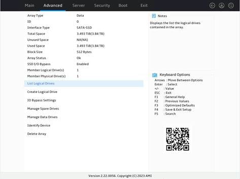
5. Select List Logical Drives and then press Enter.
Figure 18 Selecting List Logical Drives
6. Select the logical drive and then press Enter.
Figure 19 Selecting the logical drive

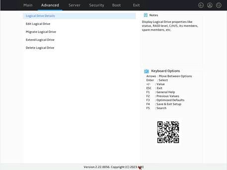
7. Select Logical Drive Details and then press Enter.
Figure 20 Selecting Logical Drive Details
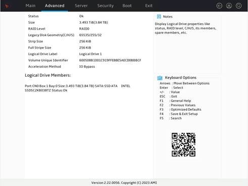
8. View the value of the Status field.
Figure 21 Viewing the value of the Status field
Viewing the status of a logical drive attached to an LSI storage controller from BIOS
1. Click the Advanced tab, select the storage controller, and then press Enter.
Figure 22 Selecting the storage controller

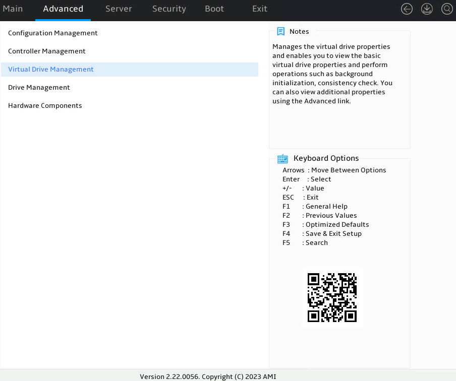
2. Select Main Menu and then press Enter.
Figure 23 Selecting Main Menu
3. Select Virtual Drive Management, and then press Enter.
Figure 24 Selecting Virtual Drive Management
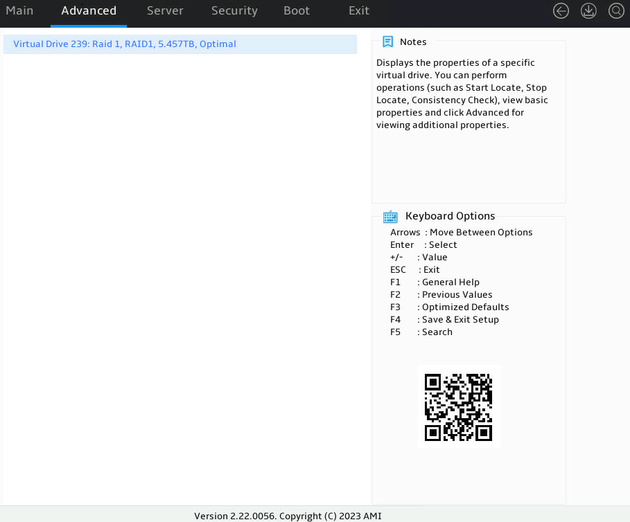
4. Selecting the logical drive and then press Enter.
Figure 25 Selecting the logical drive
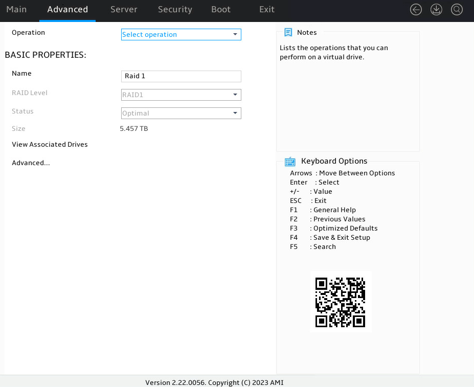
5. View the value of the Status field.
Figure 26 Viewing the value of the Status field
Logical drive status description
Table 2 Logical drive status description
|
Status |
Description |
|
Optimal |
The logical drive is operating correctly. |
|
Degraded |
Some member drives of the logical drive are faulty and require prompt replacement. |
|
Rebuilding |
The RAID array is being rebuilt to reconstruct data and recover from the degraded state. |
|
Offline |
The logical drive is corrupt and inaccessible. |
|
Suboptimal |
One member drive in the RAID 6 or RAID 60 logical drive has failed. If more than one member drive has failed, the logical drive is placed in Degraded state. This status is available only for RAID 6 and RAID 60 logical drives. |
|
Morphing |
Data is being migrated between drives or the RAID array is changing to a new RAID level. |
|
Copying |
Data is being copied from the hot spare drive back to the replacement drive of a failed drive. When this operation is complete, the hot spare returns to the hot standby state. |
|
Partially Degraded |
The number of faulty or offline physical drives on the logical drive is large but has not exceeded the maximum number of faulty drives supported by the RAID level. This status is available only for RAID 6 and RAID 60 logical drives. |
RAID array failure
The management tool displays the RAID array status information. When a RAID array fails, the management tool displays the RAID array status as Degraded or Failed.
· If the RAID array status is Degraded, examine the status of member drives, and replace the failed drives with new drives. For more information, see "Drive failure."
· If the RAID array status is Failed, select the failed RAID array, and use the Force Online function to force the RAID array to come online.
¡ If the operation succeeds, you can use the migration function to migrate the data in the RAID array.
¡ If the operation fails, you must reconfigure the RAID array.
|
|
IMPORTANT: · The Force Online operation might modify the data in the RAID array. Evaluate whether this operation is necessary before performing it. · The embedded RSTe RAID controller does not support the Force Online function. If the RAID array status is Failed, reconfigure the RAID array. |
Replacing a storage controller
To avoid data loss or damage when you replace a storage controller, make sure the following parameters are consistent before and after replacement:
· Storage controller model.
· BIOS boot mode.
· Storage controller firmware version.
· Storage controller operating mode.
· First boot option if the storage controller operates in legacy mode.
This section uses an HBA-1000-M2-1 storage controller as an example to describe how to replace a storage controller.
Replacing a storage controller in UEFI mode
Prerequisites
1. Access the storage controller configuration screen.
2. View the operating mode and firmware version of the storage controller to be replaced.
Figure 27 Viewing storage controller information
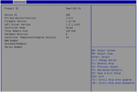
Table 3 Parameter description
|
Parameter |
Description |
|
Hardware Revision |
Hardware version. |
Replacing the storage controller
1. Replace the storage controller.
For more information, see the storage controller replacement procedure in the user guide for the server.
2. Configure the new storage controller. Make sure the replaced and newly installed storage controllers operate in the same mode and have the same firmware version.
Replacing a storage controller in legacy mode
Prerequisites
1. Access the storage controller configuration screen.
2. View the operating mode and firmware version of the storage controller to be replaced.
3. View the first boot option.
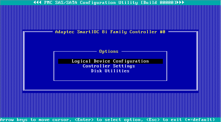
4. On the screen as shown in Figure 28, select Logical Device Configuration, and press Enter.
Figure 28 Storage controller configuration screen
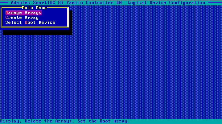
The screen as shown in Figure 29 opens.
Figure 29 Logical Device Configuration screen
5. Identify the first boot option.
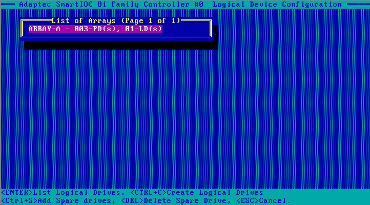
¡ If the operating system is installed on a logical drive, select Manage Arrays and press Enter to open the screen as shown in Figure 30. The first logical drive on the list is the first boot option.
Figure 30 Manage Arrays screen
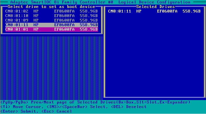
¡ If the operating system is installed on a physical drive, select Select Boot Device and press Enter to open the screen as shown in Figure 31. The first drive in the Selected Drives area on the right is the first boot option.
Replacing a storage controller
1. Replace the storage controller.
For more information, see the storage controller replacement procedure in the user guide for the server.
2. Configure the storage controller. Make sure the replaced and the newly installed storage controller operate in the same mode and have the same firmware version.
3. Configure the first boot option. Make sure the first boot option remains unchanged after the storage controller replacement.
Configuring the system to identify the new storage controller
After a replacement, storage controller consistency check might fail if RAID arrays have been built by using the replaced storage controller. This is because RAID configuration information is saved on both the storage controller and drives.
The failure might cause the controller to stop operating if the controller's boot mode is set to Stop on Error. The server cannot identify the new storage controller and the BIOS displays Failed on the Advanced > Driver Health > AVAGO EFI SAS Driver page.
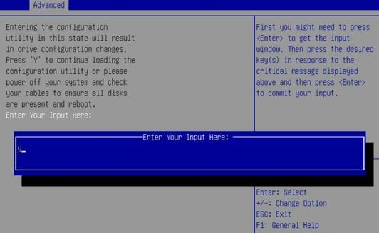
To solve this issue, perform the following tasks:
1. On the BIOS setup screen, select Advanced > Driver Health > AVAGO EFI SAS Driver, and press Enter.
2. Select the storage controller, and press Enter.
3. As shown in Figure 32 and Figure 33, enter C or Y as prompted.
Figure 32 Identifying a storage controller (1)

Figure 33 Identifying a storage controller (2)