- Table of Contents
-
- H3C G6 Servers Storage Controller User Guide-6W100
- 00-Preface
- 01-Storage controller overview
- 02-Storage controller features
- 03-Configuring a VROC SATA RAID controller
- 04-Configuring an NVMe VROC module
- 05-Configuring an LSI-9540 or 9560 storage controller
- 06-Configuring a P460, P2404 or P4408 storage controller
- 07-Configuring an LSI 9500 series storage controller
- 08-Configuring a RAID-MARVELL-SANTACRUZ-LP-2i storage controller
- 09-Configuring a RAID-MARVELL-M.2 storage controller
- 10-Appendix A Troubleshooting storage controllers
- 11-Appendix B RAID arrays and fault tolerance
- Related Documents
-
| Title | Size | Download |
|---|---|---|
| 09-Configuring a RAID-MARVELL-M.2 storage controller | 3.62 MB |
Configuring a RAID-MARVELL-M.2 storage controller
About the RAID-MARVELL-M.2 storage controller
The RAID-MARVELL-M.2 standard storage controller can be installed onto a riser card to provide limited RAID support for the system, which improves read/write performance and data security.
Features
RAID levels
Table 1 shows the number of drives required by each RAID level and the maximum number of failed drives supported by each RAID level.
Table 1 RAID levels and the numbers of drives for each RAID level
|
RAID level |
Min. drives required |
Max. failed drives |
|
RAID 0 |
2 |
0 |
|
RAID 1 |
2 |
1 |
Restrictions and guidelines for RAID configuration
· As a best practice, install drives that do not contain RAID information.
· The RAID-MARVELL-M.2 storage controller does not support NVMe M.2 SSDs.
· For efficient use of storage, use drives that have the same capacity to build RAID 1. If the drives have different capacities, the lowest capacity is used across all drives in the RAID.
Configuring RAID arrays in UEFI mode
This section describes how to configure RAID arrays through a RAID-MARVELL-M.2 storage controller in UEFI mode. For more information about how to access the BIOS setup utility and set the boot mode to UEFI, see the BIOS user guide for the server.
The BIOS screens might vary by BIOS version and the screens used in this section are for illustration only.
Controller configuration tasks at a glance
To configure controller settings in UEFI mode, perform the following tasks:
· Accessing the storage controller configuration screen
· Viewing physical drive information
· Viewing logical drive information
· Viewing storage controller information
Accessing the storage controller configuration screen
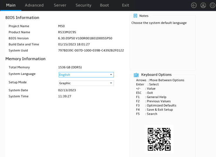
1. After the server is powered on or restarts, access the BIOS. Press Delete, Esc, or F2 as prompted during server POST to open the BIOS setup screen as shown in Figure 1.
For how to navigate screens and modify settings, see the operation instructions at the lower right corner.
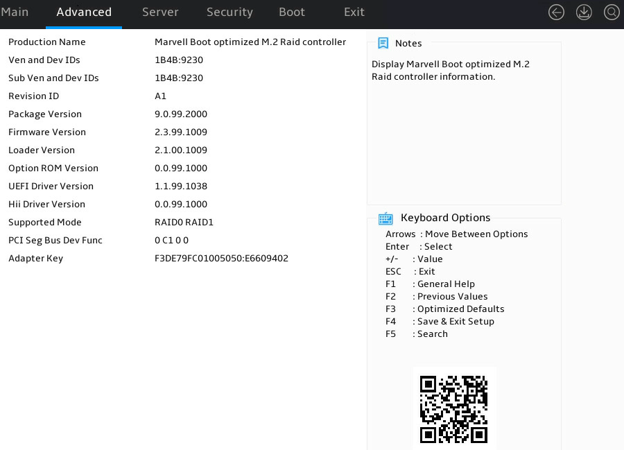
2. Select Advanced > Marvell Boot optimized M.2 Raid controller, and press Enter.
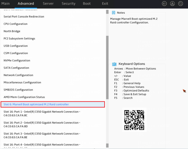
The storage controller configuration screen opens. Tasks can be performed from this screen are shown in Table 2.
Figure 3 Storage controller configuration screen
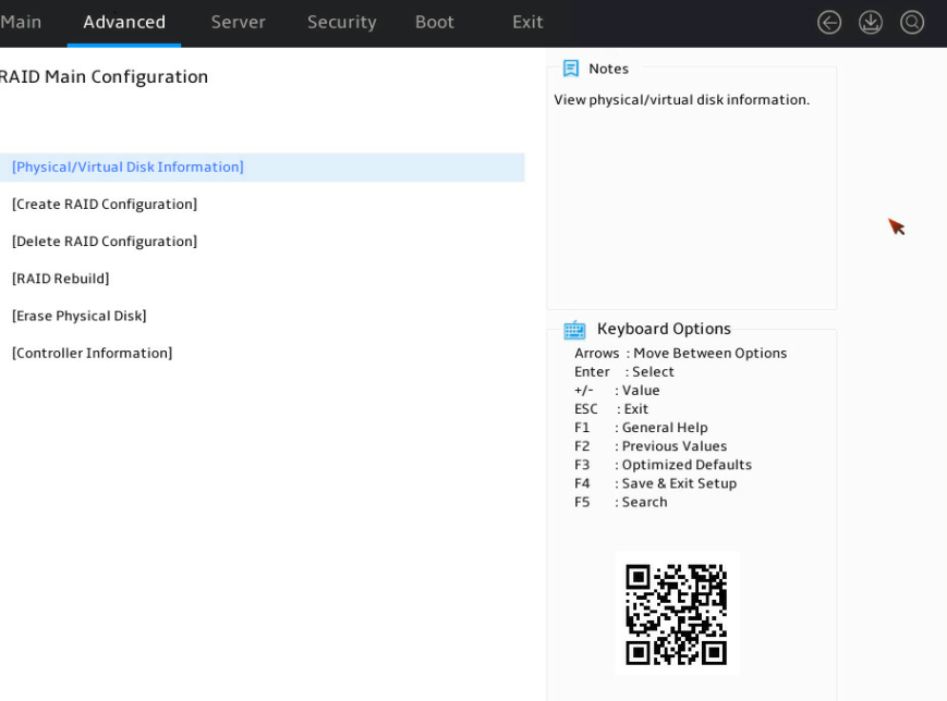
Table 2 Storage controller configuration tasks
|
Task type |
Option |
Description |
|
Information query |
Physical/Virtual Device Information |
Display summary and detailed information about installed physical drives and logical drives. |
|
Controller Information |
Display detailed information about the storage controller. |
|
|
RAID configuration |
Create RAID Configuration |
Create RAIDs. |
|
Delete RAID Configuration |
Delete RAIDs. |
|
|
Rebuild RAID Configuration |
Rebuild RAIDs. |
|
|
Erase Physical Disk |
Erase physical drives. |
Configuring RAID 0
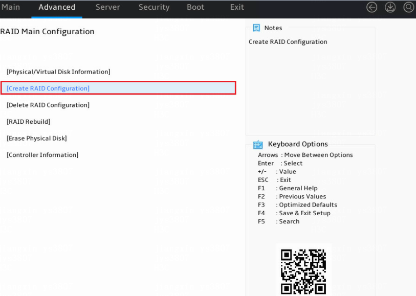
1. Access the storage controller configuration screen, select Create RAID Configuration, and press Enter.
Figure 4 Storage controller configuration screen
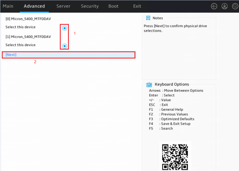
2. Select two member drives, select Next, and press Enter.
Figure 5 Selecting member drives

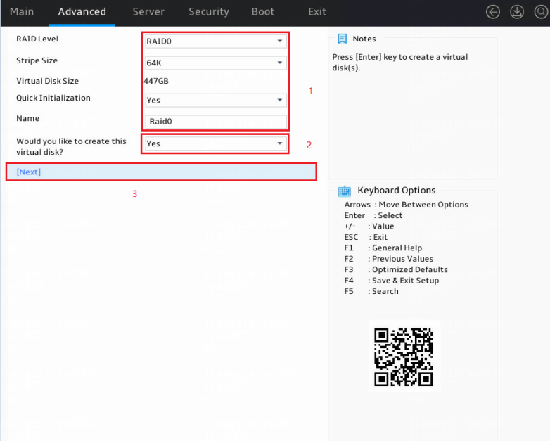
3. Configure parameters as needed and set the Would you like to create this virtual disk? field to Yes. In the dialog box that opens, press Enter. Then, select Next and press Enter.
The parameter description is in Table 3.
Figure 6 Configuring RAID information
|
Parameter |
Description |
|
RAID Level |
RAID level. Options include: · RAID 0. · RAID 1. |
|
Stripe Size |
Stripe size. Options include: · 32K. · 64K. |
|
Initialization |
Initialization methods. Options include: · Quick—Default. · Back Ground—This option is supported only in RAID 1. · None. |
|
Name |
Name of the logical drive. |
Configuring RAID 1
1. Access the storage controller configuration screen, select Create RAID Configuration, and press Enter.
Figure 7 Storage controller configuration screen

2. Select two member drives, select Next, and press Enter.
Figure 8 Selecting member drives
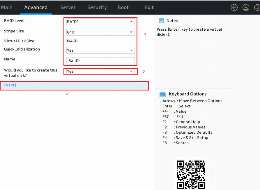
3. Configure parameters as needed and set the Would you like to create this virtual disk? field to Yes. In the dialog box that opens, press Enter. Then, select Next and press Enter.
See the parameter description in Table 3.
Figure 9 Configuring RAID information
Deleting a RAID array
This feature deletes damaged RAID arrays or RAID arrays that cannot meet requirements.
To delete a RAID array:
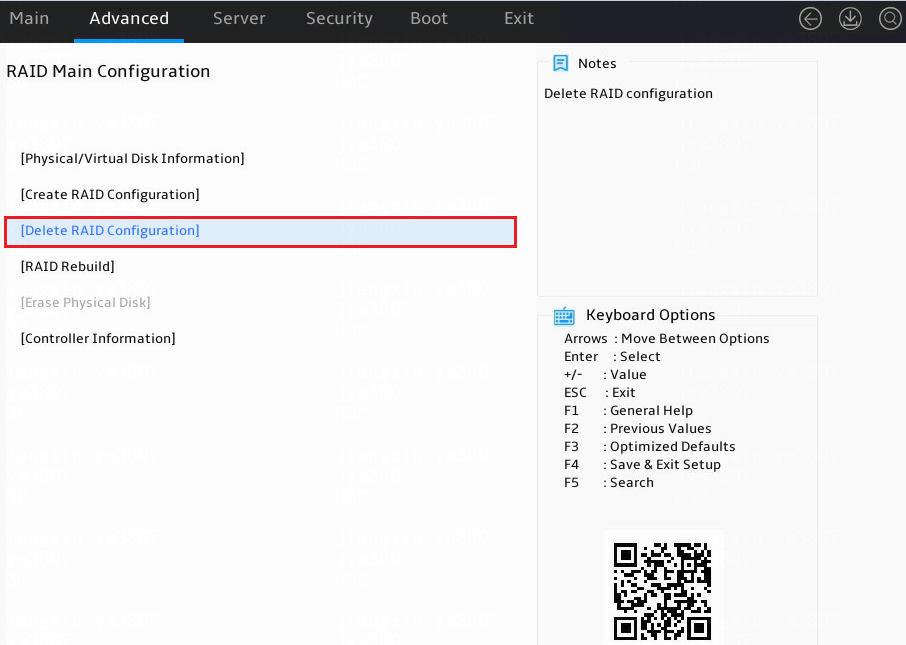
1. Access the storage controller configuration screen, select Delete RAID Configuration, and press Enter.
Figure 10 Storage controller configuration screen
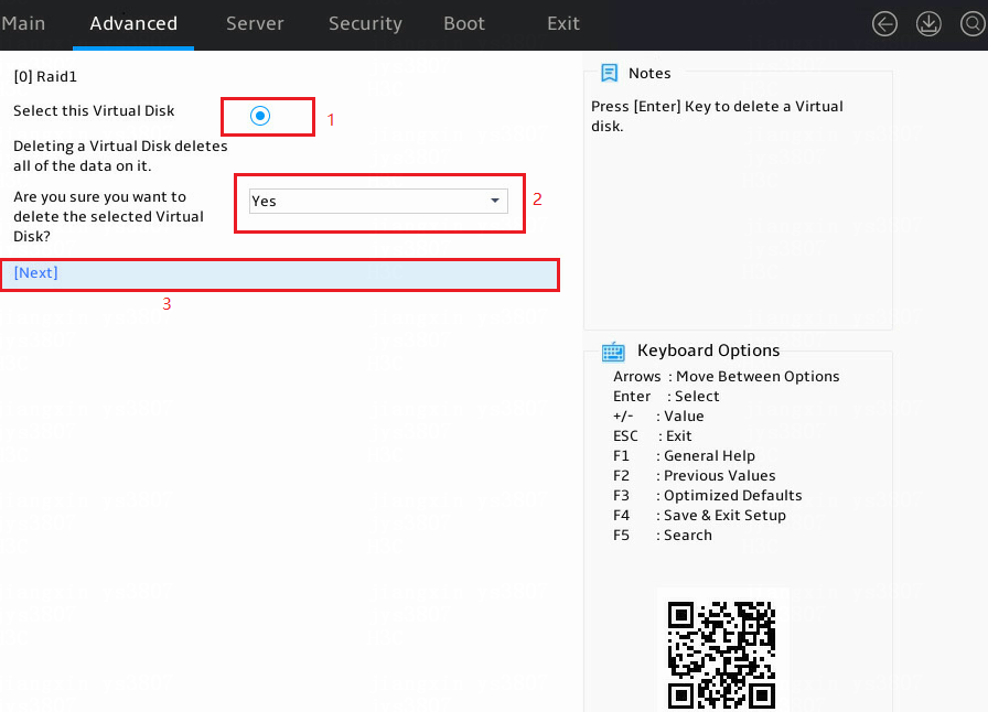
2. Perform the following tasks:
a. Select a target logical drive.
b. Set the Are you sure you want to delete the selected Virtual Disk? field to Yes. In the dialog box that opens, press Enter.
c. Select Next and press Enter.
Figure 11 Deleting a RAID array
Rebuilding a RAID array
This feature rebuilds the RAID array for drive replacement when a member drive in RAID 1 failed.
To rebuild a RAID array:
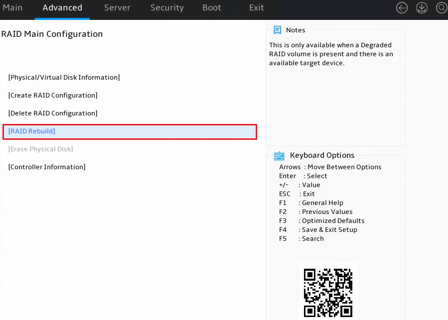
1. Access the storage controller configuration screen, select Rebuild RAID Configuration, and press Enter.
Figure 12 Storage controller configuration screen
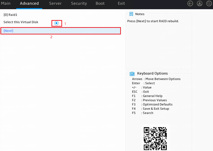
2. Select a logical drive to be rebuilt, select Next, and then press Enter.
If no logical drive is displayed, it indicates that no logical drive is available or no logical drive can be rebuilt.
Figure 13 Rebuilding a RAID array
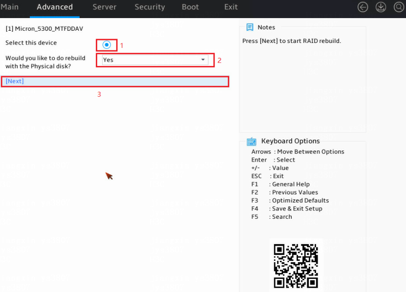
3. Select physical drives for logical drive rebuilding, and set the Would you like to do rebuild with the Physical disk field to Yes. In the dialog box that opens, press Enter. Then, select Next and press Enter.
If no physical drive is displayed, it indicates that no physical drive is available.
Figure 14 Selecting physical drives
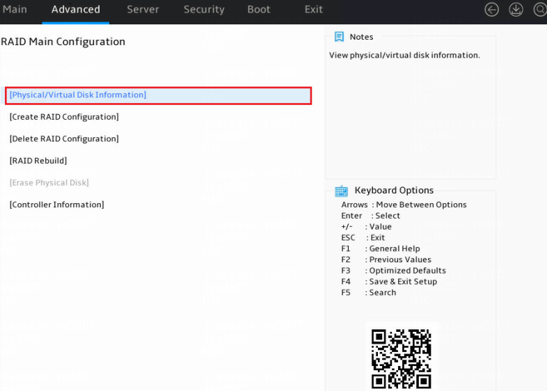
Viewing physical drive information
1. Access the storage controller configuration screen, select Physical/Virtual Disk Information, and press Enter.
Figure 15 Storage controller configuration screen
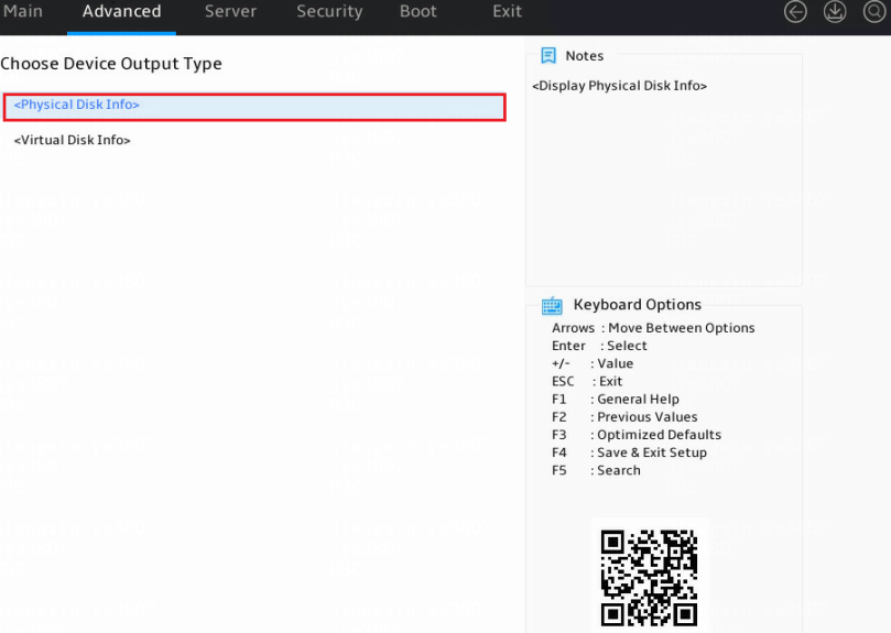
2. Select Physical Disk Info and press Enter.
Figure 16 Accessing physical drive information
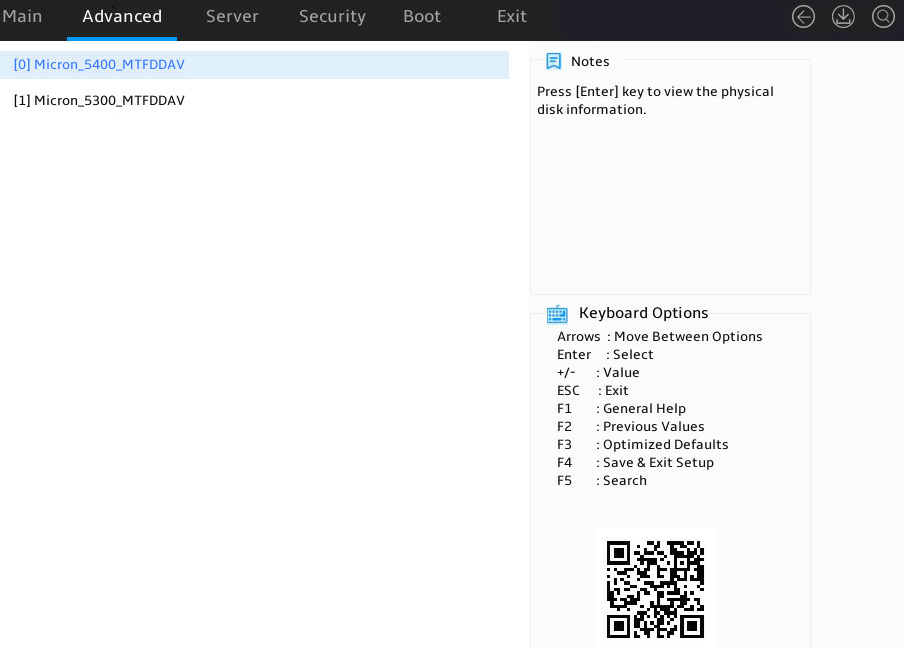
3. Select the target physical drive and press Enter.
Figure 17 Selecting a physical drive
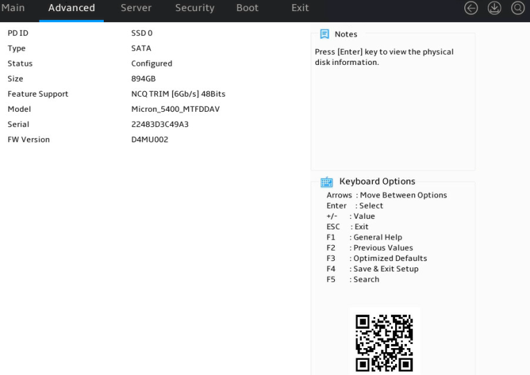
The physical drive details screen opens. Parameters are as described in Table 4.
Figure 18 Physical drive details screen
|
Parameter |
Description |
|
PD ID |
Physical drive slot. Options include: · 0—Physical drive slot marked Bay 1. · 1—Physical drive slot marked Bay 2. |
|
Type |
Physical drive type. |
|
Status |
Physical drive status. |
|
Model Name |
Physical drive model. |
|
Serial Number |
Physical drive serial number. |
|
FW Version |
Physical drive firmware version. |
|
Size |
Physical drive capacity. |
Viewing logical drive information
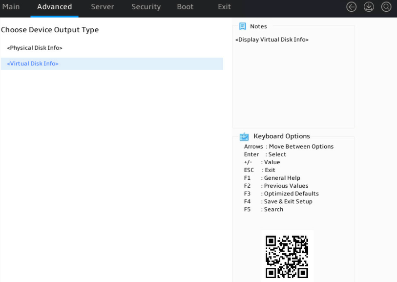
1. Access the storage controller configuration screen, select Physical /Virtual Device Information, and press Enter. Select Virtual Disk Info and press Enter.
Figure 19 Accessing logical drive information
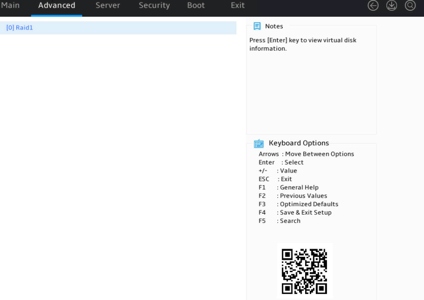
2. Select a target logical drive and press Enter.
Figure 20 Selecting a logical drive
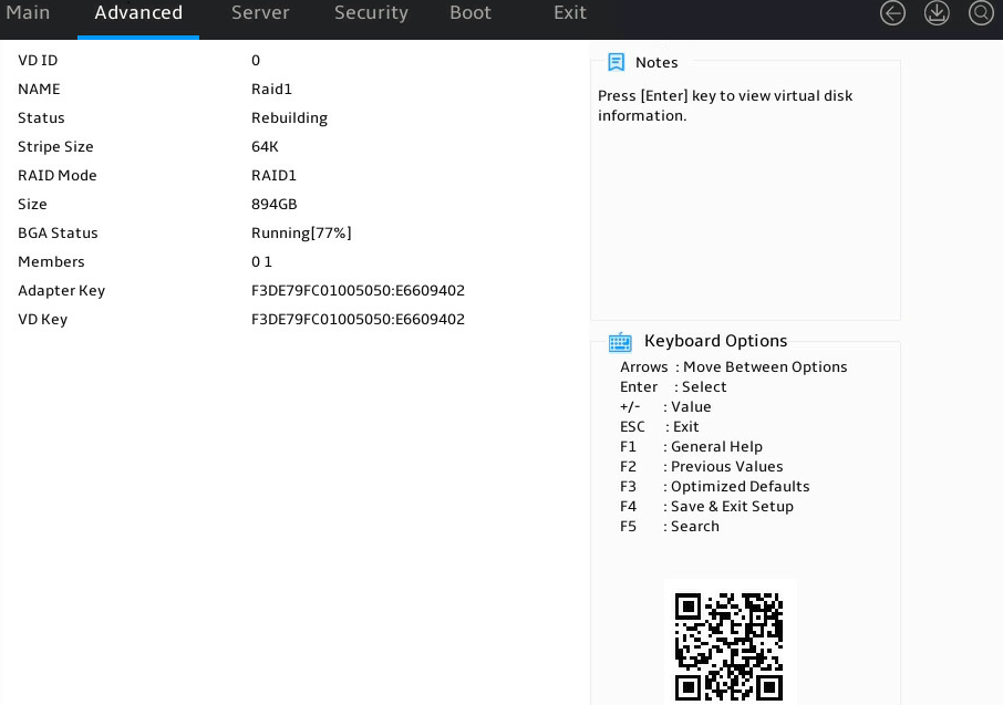
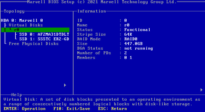
The logical drive details screen opens. Parameters are as described in Table 5.
Figure 21 Logical drive details screen
|
Parameter |
Description |
|
VD ID |
Logical drive number. Options include 0 and 1. |
|
NAME |
Logical drive name. |
|
Status |
Logical drive status. Options include: · Functional. · Degrade. · Offline. · Rebuilding. |
|
Stripe Size |
Stripe size of each physical drive. |
|
RAID Mode |
RAID level. |
|
BGA Type |
Background task type. Options include: · Initialization—RAID initialization in progress. · Rebuild—RAID rebuilding in progress. · MediaPatrol—Media patrol for logical drives in progress. · None. |
|
Size |
Logical drive capacity. |
|
BGA Status |
Background task status. Options include: · None. · RUNNING—Task progress in percentage. |
|
Members |
Displays member drives by ID. |
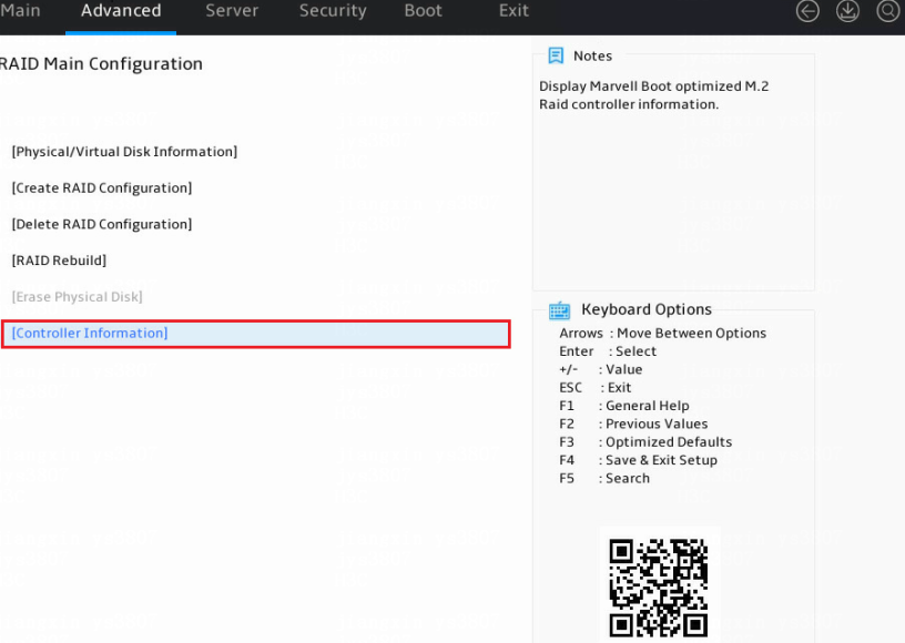
Viewing storage controller information
Access the storage controller configuration screen, select Controller Information, and press Enter.
Figure 22 Storage controller configuration screen
The storage controller information screen opens.
Figure 23 Storage controller information
Configuring RAID arrays in legacy mode
This section describes how to configure RAID arrays through a RAID-MARVELL-M.2 storage controller in legacy mode. For more information about how to access the BIOS setup utility and set the boot mode to legacy, see the BIOS user guide for the server.
The BIOS screens might vary by BIOS version and the screens used in this section are for illustration only.
Controller configuration tasks at a glance
To configure controller settings in legacy mode, perform the following tasks:
· Accessing the storage controller configuration screen.
· Viewing physical drive information
· Viewing logical drive information
Accessing the storage controller configuration screen
1. During server POST as shown in Figure 24, press Ctrl+M.
For how to navigate screens and modify settings, see the operation instructions at the bottom of the screen.
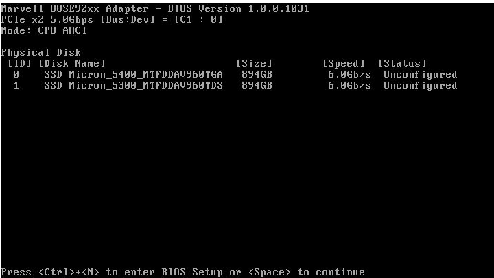
The storage controller configuration screen opens as shown in Figure 25.
Figure 25 Storage controller configuration screen

Configuring RAID 0
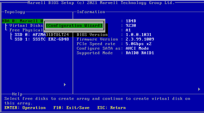
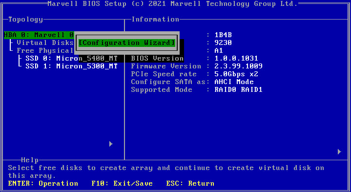
1. Access the storage controller configuration screen, select HBA 0: Marvell 0, press Enter, and select Configuration Wizard.
Figure 26 Storage controller configuration screen
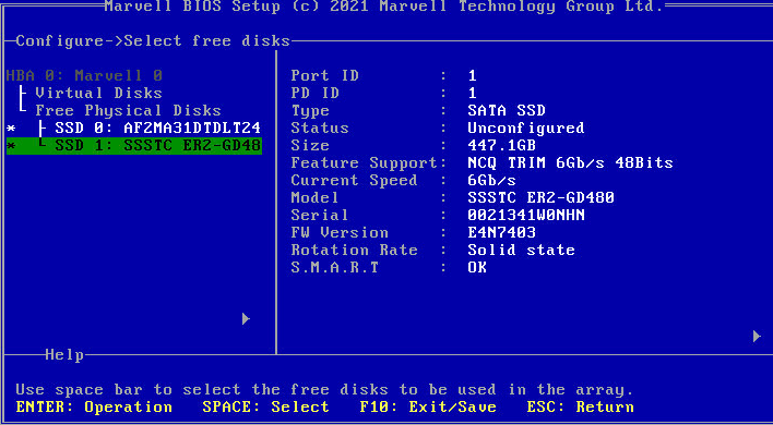
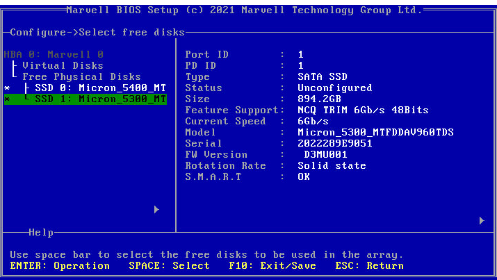
2. Press Space to select two member drives and press Enter.
Figure 27 Selecting member drives
3. Configure parameters as needed and click Next. In the dialog box that opens, click Y.
The parameter description is in Table 6.
Figure 28 Configuring RAID information
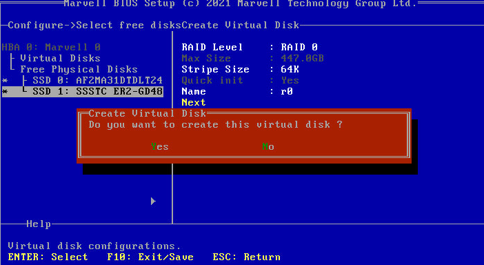
Figure 29 Finishing configuring a RAID array
|
Parameter |
Description |
|
RAID Level |
RAID level. Options include: · RAID 0. · RAID 1. |
|
Stripe Size |
Stripe size. Options include: · 32K. · 64K. |
|
Name |
Name of the logical drive. |
Configuring RAID 1
1. Access the storage controller configuration screen, select HBA 0: Marvell 0, press Enter, and select Configuration Wizard.
Figure 30 Storage controller configuration screen
2. Press Space to select two member drives and press Enter.
Figure 31 Selecting member drives
3. Configure parameters as needed and click Next. In the dialog box that opens, click Y.
See Table 6 for the parameter description.
Figure 32 Configuring RAID information
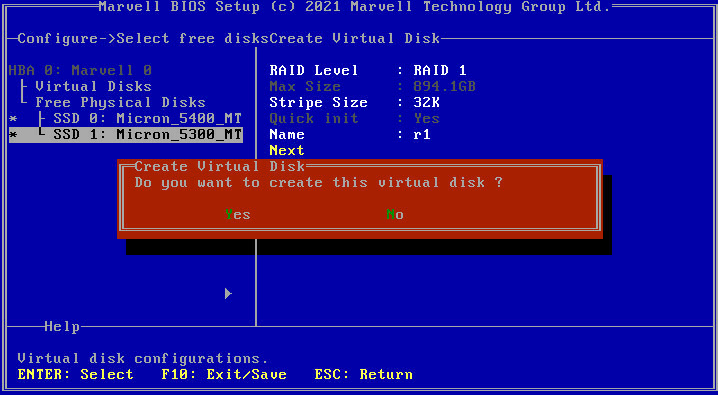
Figure 33 Finishing configuring a RAID array
Deleting a RAID array
This feature deletes damaged RAID arrays or RAID arrays that cannot meet requirements.
To delete a RAID array:
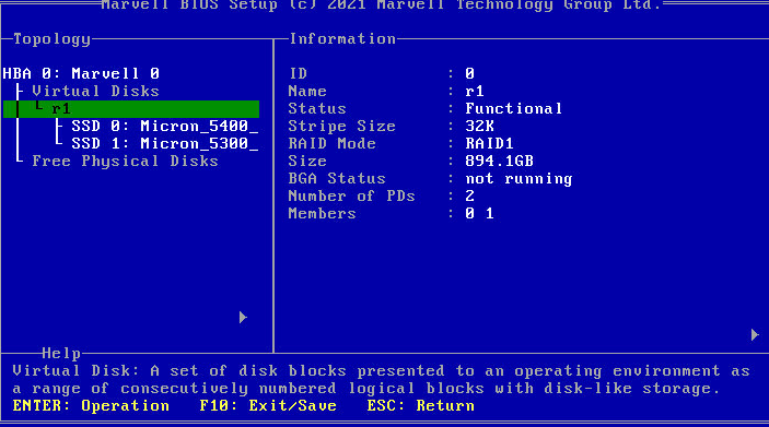
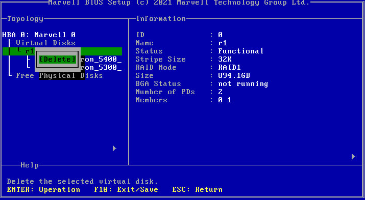
1. Access the storage controller configuration screen, select the target logical drive, press Enter, and select Delete.
Figure 34 Storage controller configuration screen
2. In all the dialog boxes that open, press Y or click Yes.
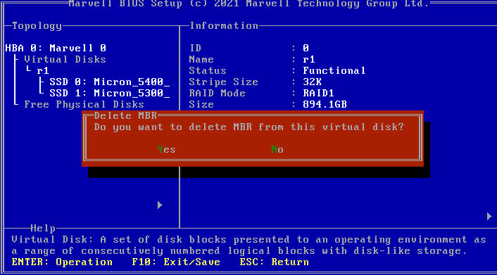
Figure 35 Deleting a RAID array
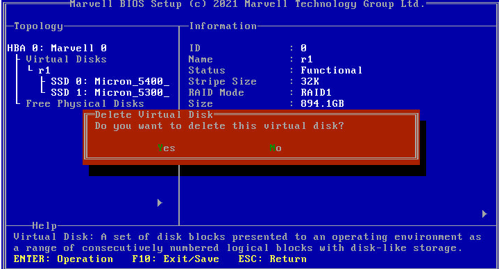
Figure 36 Deleting MBR
Viewing physical drive information
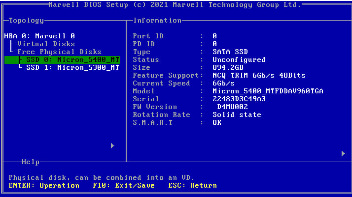
Access the storage controller configuration screen, select the target physical drive, and view the related information.
Figure 37 Viewing physical drive information

Viewing logical drive information
Access the storage controller configuration screen, select the target logical drive, and view related information.
Figure 38 Viewing logical drive information
Configuring RAID arrays in the operating system
This section introduces how to configure RAID arrays in the operating system by using a RAID controller tool.
Installing a RAID controller tool
Install a RAID controller tool in the operating system to help you build RAID arrays, update firmware, and view physical drive information.
Install a RAID controller tool in the operating system and then assign permissions of using the tool to the current user.
Syntax
chmod 777 mvcli
Examples
[root@localhost Marvell]# chmod 777 mvcli
Accessing the RAID controller configuration CLI
Syntax
./mvcli
Examples
[root@localhost Marvell]# ./mvcli
SG driver version 3.5.36.
CLI Version: 4.1.99.42 RaidAPI Version: 5.0.24.1001
Welcome to RAID Command Line Interface.
Viewing the RAID controller information
Syntax
info -o hba
Examples
> info -o hba
Adapter ID: 0
Product: 1b4b-9230
Sub Product: 1b4b-9230
Chip revision: A1
Max PCIe speed: 5Gb/s
Current PCIe speed: 5Gb/s
Max PCIe link: 2
Current PCIe link: 2
Rom version: 0.0.99.1000
Package version: 9.0.99.2000
BIOS version: 1.0.0.1031
Firmware version: 2.3.99.1009
Boot loader version: 2.1.00.1009
# of ports: 3
Buzzer: Not supported
Supported port type: SATA
Supported RAID mode: RAID0 RAID1 JBOD
Maximum disk in one VD: 2
PM: Not supported
Expander: Not supported
Maximum supported disk: 2
Maximum supported VD: 1
Max total blocks: 128
Features: rebuild,media patrol
Advanced features: event sense code,multi VD,spc 4,image health,timer,ata pass through,oem data
Advanced features 2: scsi pass through,flash
Max buffer size: 3
Stripe size supported: 32K 64K
Image health: Healthy
Autoload image health: Healthy
Boot loader image health: Healthy
Firmware image health: Healthy
Boot ROM image health: Healthy
HBA info image health: Healthy
Viewing physical drive information
Syntax
info -o pd
Examples
> info -o pd
Physical Disk Information
----------------------------
Adapter: 0
PD ID: 0
Type: SATA PD
Linked at: HBA port 0
Size: 937692504 K
Write cache: not supported
SMART: supported (on)
NCQ: supported (on)
48 bits LBA: supported
supported speed: 1.5 3 6 Gb/s
Current speed: 6 Gb/s
model: Micron_5400_MTFDDAV960TGA
Serial: 22483D3C49A3
Firmware version: D4MU002
Locate LED status: Not Support
Running OS: no
SSD Type: SSD
block ids: 0
associated VDs: 0
PD valid size: 0 K
Adapter: 0
PD ID: 1
Type: SATA PD
Linked at: HBA port 1
Size: 937692504 K
Write cache: not supported
SMART: supported (on)
NCQ: supported (on)
48 bits LBA: supported
supported speed: 1.5 3 6 Gb/s
Current speed: 6 Gb/s
model: Micron_5300_MTFDDAV960TDS
Serial: 2022289E9051
Firmware version: D3MU001
Locate LED status: Not Support
Running OS: no
SSD Type: SSD
block ids: 4
associated VDs: 0
PD valid size: 0 K
Total # of PD: 2
Viewing logical drive information
Syntax
info -o vd
Examples
> info -o vd
Virtual Disk Information
-------------------------
id: 0
name: Raid1
status: functional
Stripe size: 64
RAID mode: RAID1
Cache mode: Not Support
size: 915651 M
BGA status: not running
Block ids: 0 4
# of PDs: 2
PD RAID setup: 0 1
Running OS: no
Total # of VD: 1
Creating a RAID array
Syntax
create -o vd -r raid level -d pd id, pd id -n name -b stripe size
Parameters
|
Argument |
Description |
Supported values |
|
raid level |
RAID level. |
· 0. · 1. |
|
pd |
Physical drive ID. |
· 0. · 1. |
|
name |
RAID name. |
N/A |
|
stripe size |
Stripe size. |
· 32. · 64. |
Examples
> create -o vd -r 1 -d 0,1 -n "Raid1" -b 64
Deleting a logical drive
Syntax
delete -o vd -i vd id
Parameters
|
Argument |
Description |
Supported values |
|
vd id |
Logical drive ID. |
N/A |
Examples
> delete -o vd -i 0
Are you sure you want to delete this virtual disk? (y or n)
y
Delete VD 0 successfully.
Troubleshooting issues
For more information about fault information collection, fault diagnosis and location, and fault troubleshooting of the storage controller, see H3C Servers Storage Controller User Guide.
Storage controller compatibility
For more information about the compatibility between the storage controller and the server, use the tool at http://www.h3c.com/en/home/qr/default.htm?id=66.
