- Table of Contents
- Related Documents
-
| Title | Size | Download |
|---|---|---|
| 02-EPON multicast configuration | 142.25 KB |
Contents
Restrictions and guidelines: EPON multicast configuration
EPON multicast tasks at a glance
Configuring basic multicast settings
Configuring multicast in IGMP snooping mode
Configuring multicast in multicast control mode
Enabling unknown multicast packet transparent transmission for UNIs
Enabling fast-leave processing for a UNI
Display and maintenance commands for ONUs
EPON multicast configuration examples
Multicast in IGMP snooping mode configuration example
Multicast in multicast control mode configuration example
Configuring EPON multicast
EPON multicast mode overview
An OLT supports remotely setting the multicast mode (including IGMP snooping mode and multicast control mode) for ONUs. For more information about IGMP snooping, see IP Multicast Configuration Guide.
Multicast in IGMP snooping mode
In IGMP snooping mode, the OLT and ONUs mainly use IGMP report, leave, and query messages to manage dynamic multicast group membership. The OLT can implement simple user multicast access control through the multicast VLAN configuration on UNIs of ONUs.
When an ONU receives an IGMP membership report from a multicast group member, the ONU forwards the message to the OLT. When multiple members of a multicast group are attached to the ONU, the OLT will receive duplicate IGMP reports from these members. To reduce IGMP reports, enable IGMP report suppression. Within each query cycle, the ONU forwards only the first IGMP report of a multicast group to the OLT. Subsequent IGMP reports from the same multicast group are not forwarded.
On the OLT, you can configure the router interface aging timer, the multicast group member port aging timer, and the query response timer for an ONU.
· Router interface aging timer—The router interface is the interface that connects the ONU to the router. The ONU receives IGMP general query messages from the router through this interface. If no IGMP general query message is received through the router interface when the router interface aging timer expires, the ONU determines that the interface is not a router interface. The router interface aging timer must be a value about 2.5 times of the general query interval. For more information about the general query interval, see IGMP in IP Multicast Configuration Guide.
· Multicast group member port aging timer—This timer determines how often multicast group members are refreshed. If the ONU does not receive an IGMP report from a multicast group member port when this timer expires, the ONU deletes the port. In a network where multicast group members change frequently, set this timer to a small value.
· Query response timer—This timer sets the response timeout time for group-specific queries. If the ONU does not receive a response before the query response timer expires for the first time, it re-sends group-specific queries and re-starts the query response timer. If the ONU still does not receive a response when the timer expires, the multicast group on the ONU is deleted.
Multicast in multicast control mode
In multicast control mode, the OLT performs the following operations:
· The OLT maintains an access control table for user multicast services to centrally manage user multicast service access rights.
· The OLT identifies users based on the user LLID and the VLAN tag (same as the UNI number) carried in uplink IGMP report messages. The OLT also determines whether a user has the right to access the requested multicast service and determines the related parameters.
· The OLT uses extended multicast control OAM packets to send the ONU a user's access right to a multicast channel. This allows the ONU to forward or shut off the multicast traffic for the user. The network management system on the OLT centrally manages multicast access control. Multicast right management is governed by the OLT and executed by ONUs. The OLT also supports the cooperation between IGMP proxy and upper-layer multicast routers to dynamically request and deliver multicast traffic.
In multicast control mode, an ONU performs the following operations:
· The ONU maintains a table for multicast address filtering and multicast forwarding. The ONU performs flow control only for the current multicast service on the ONU.
· The ONU adds VLAN tags to untagged IGMP report and leave messages to identify users and transparently sends the messages to the OLT. The VLAN tag ID is the same as the UNI number. For example, the packets received on UNI 1 are tagged with VLAN ID 1. The ONU adds or deletes the group address filtering and multicast forwarding entries on the ONU based on the multicast control OAM packets delivered by the OLT. The multicast control OAM packets contain a series of multicast control entries. Based on the action taken on the entries, the ONU forwards or shuts off multicast traffic.
Restrictions and guidelines: EPON multicast configuration
In an EPON system, support of ONUs for EPON multicast varies by ONU model and software version.
EPON features are supported only on the default MDC. For more information about MDCs, see Virtual Technologies Configuration Guide.
Layer 3 multicast is not supported on the VLAN interface for the multicast VLAN to which a UNI on an RONU interface is assigned by using the uni multicast vlan command.
EPON multicast tasks at a glance
To configure EPON multicast, perform the following tasks:
1. Configuring basic multicast settings
2. Setting the multicast mode
Choose one of the following options.
¡ Configuring multicast in IGMP snooping mode
¡ Configuring multicast in multicast control mode
3. (Optional.) Enabling unknown multicast packet transparent transmission for UNIs
4. (Optional.) Enabling fast-leave processing for a UNI
5. (Optional.) Configuring CDR on an OLT
Perform this task to enable an OLT to record basic access information of users.
Configuring basic multicast settings
Restrictions and guidelines
For more information about IGMP-related commands, see IGMP snooping commands in IP Multicast Command Reference.
The IGMP snooping querier might send IGMP general queries with the source IP address 0.0.0.0. The ONU PON interface that receives such queries will not be maintained as a dynamic router interface. This might prevent the associated dynamic IGMP snooping forwarding entry from being correctly created at the data link layer and eventually cause multicast traffic forwarding failures. To avoid this problem, you can configure a non-all-zero IP address as the source IP address of the IGMP queries on the IGMP snooping querier.
Configuration procedure
|
Step |
Command |
Remarks |
|
1. Enter system view. |
system-view |
N/A |
|
2. Enter FTTH view. |
ftth |
N/A |
|
3. Map multicast IP addresses to a multicast VLAN. |
multicast vlan-id vlan-id ip ip-address-list |
By default, no multicast IP addresses are mapped to a multicast VLAN. A multicast IP address can be mapped to only one multicast VLAN. When receiving an IGMP report message, the OLT verifies whether the multicast IP address in the message belongs to the multicast VLAN. · If the address belongs to the multicast VLAN, the OLT generates a multicast forwarding entry for the multicast VLAN. · If the address does not belong to the multicast VLAN, the OLT drops the message. |
|
4. Return to system view. |
quit |
N/A |
|
5. Enable IGMP snooping globally. |
igmp-snooping |
By default, IGMP snooping is disabled globally. |
|
6. Enable IGMP snooping in multicast VLANs. |
· Enable IGMP snooping in multiple VLANs. · Execute the following commands in sequence to
enable IGMP snooping in one VLAN. |
By default, IGMP snooping is disabled in a VLAN. |
|
7. Return to system view. |
quit |
N/A |
|
8. Enter multicast VLAN view. |
vlan vlan-id |
N/A |
|
9. Enable IGMP snooping querier. |
igmp-snooping querier |
By default, IGMP snooping querier is disabled. If a network does not contain Layer 3 multicast devices, you must enable IGMP snooping querier on Layer 2 devices for them to generate and maintain multicast forwarding entries at the data link layer. |
|
10. Configure the source IP address for IGMP general queries. |
igmp-snooping general-query source-ip ip-address |
By default, the source IP address of IGMP general queries is the IP address of the current VLAN interface. If the current VLAN interface does not have an IP address, the source IP address is 0.0.0.0. |
|
11. Configure the source IP address for IGMP group-specific queries. |
igmp-snooping special-query source-ip ip-address |
By default, the source IP address of IGMP group-specific queries is one of the following: · The source address of IGMP group-specific queries if the IGMP snooping querier of the VLAN has received IGMP general queries. · The IP address of the current VLAN interface if the IGMP snooping querier does not receive an IGMP general query. · 0.0.0.0 if the IGMP snooping querier does not receive an IGMP general query and the current VLAN interface does not have an IP address. |
|
12. (Optional.) Enable dropping unknown multicast traffic. |
igmp-snooping drop-unknown |
N/A |
Configuring multicast in IGMP snooping mode
Restrictions and guidelines
The onu protocol igmp-snooping suppression and onu protocol igmp-snooping timer commands are available on the ET704 ONU.
Configuration procedure
|
Step |
Command |
Remarks |
|
1. Enter system view. |
system-view |
N/A |
|
2. Enter ONU or RONU interface view. |
· Enter ONU interface view. · Enter RONU interface view. |
N/A |
|
3. Set the multicast mode to IGMP snooping. |
multicast mode igmp-snooping |
By default, the multicast mode of an ONU is IGMP snooping. |
|
4. Assign a UNI to multicast VLANs. |
uni uni-number multicast vlan vlan-id-list |
By default, a UNI is not assigned to any multicast VLANs. |
|
5. (Optional.) Configure a UNI to process downlink multicast flows. |
· Configure a UNI to remove the VLAN tags
of downlink multicast flows. · Configure a UNI to translate the VLAN
IDs for downlink multicast flows. |
Choose one of the two options, which are mutually exclusive. By default, a UNI does not process VLAN tags of downlink multicast flows. |
|
6. (Optional.) Configure advanced multicast parameters. |
· Configure the number of multicast
channels that users can access at the same time on a UNI. · Set IGMP snooping timers. · Enable IGMP membership report suppression or
IGMP leave suppression. |
By default: · The users on a UNI can access 64 multicast channels at the same time. · The multicast group member port aging timer is 260 seconds. The query response timer is 1 second. The router interface aging timer is 105 seconds. · IGMP leave suppression is enabled, and IGMP membership report suppression is disabled. |
Configuring multicast in multicast control mode
|
Step |
Command |
Remarks |
|
1. Enter system view. |
system-view |
N/A |
|
2. Enter ONU or RONU interface view. |
· Enter ONU interface view. · Enter RONU interface view. |
N/A |
|
3. Set the multicast mode to multicast control. |
multicast mode multicast-control |
By default, the multicast mode of an ONU is IGMP snooping. |
|
4. (Optional.) Configure a UNI to process downlink multicast flows. |
· Configure a UNI to remove the VLAN tags
of downlink multicast flows. · Configure a UNI to translate the VLAN
IDs for downlink multicast flows. |
Choose one of the two options, which are mutually exclusive. By default, a UNI does not process VLAN tags of downlink multicast flows. |
|
5. (Optional.) Configure advanced multicast parameters. |
· Set the multicast group member port
aging timer. · Configure the access to multicast channels on
a UNI. |
By default: · The multicast group member port aging timer is 260 seconds. · The access to multicast channels is not configured on a UNI. |
Enabling unknown multicast packet transparent transmission for UNIs
About this task
With this feature enabled, UNIs on an ONU process frames destined for the specified multicast MAC addresses as follows:
· If the destination MAC address is 0100-ffff-ffff (referred to as global transparent transmission MAC address), the UNIs flood the multicast packets destined for the MAC addresses starting with 0x0100.
When this feature is configured, as a best practice, do not configure known multicast services.
· If the destination MAC address is a value except 0100-ffff-ffff (referred to as non-global transparent transmission MAC address), the UNIs multicast the multicast packets destined for the MAC address.
This feature forwards only unknown multicast packets. As a best practice, make sure the MAC address does not overlap with that of a known multicast service.
Restrictions and guidelines
On an ONU interface, the global transparent transmission MAC address configuration is mutually exclusive with the non-global transparent transmission MAC address configuration.
The global transparent transmission MAC address can be configured only by using the onu protocol transparent-multicast dest-mac mac-address command and does not support the vlan keyword.
Non-global transparent transmission MAC address configuration is supported in multicast control mode.
Support for the non-global transparent transmission MAC address configuration varies by device model.
Configuration procedure
|
Step |
Command |
Remarks |
|
1. Enter system view. |
system-view |
N/A |
|
2. Enter ONU or RONU interface view. |
· Enter ONU interface view. · Enter RONU interface view. |
N/A |
|
3. Enable unknown multicast packet transparent transmission for UNIs. |
· Enable unknown multicast packet
transparent transmission for all UNIs on the ONU: · Enable unknown multicast packet transparent
transmission for a UNI on the ONU: |
Use either command. The two commands are mutually exclusive. By default, unknown multicast packet transparent transmission is disabled on UNIs. The ONU might drop unknown multicast packets. If you do not specify the vlan keyword, VLAN 1 is used. |
Enabling fast-leave processing for a UNI
About this task
This feature immediately removes a UNI from the outgoing interface list of the forwarding table when the UNI receives an IGMP leave message for a multicast group. Then, when the ONU receives IGMP group-specific queries for that multicast group, the ONU does not forward them to that UNI.
If only one host is attached to a UNI, fast-leave processing helps improve bandwidth and resource usage. If multiple hosts in the same multicast group are attached to a UNI, when one host leaves the multicast group, the other hosts cannot receive multicast data.
Before you enable fast-leave processing, make sure the ONU is operating in IGMP snooping mode. This feature takes effect only for IGMPv2 or IGMPv3 clients.
Configuration procedure
|
Step |
Command |
Remarks |
|
1. Enter system view. |
system-view |
N/A |
|
2. Enter ONU or RONU interface view. |
· Enter ONU interface view. · Enter RONU interface view. |
N/A |
|
3. (Optional.) Set the multicast mode to IGMP snooping. |
multicast mode igmp-snooping |
By default, the multicast mode of an ONU is IGMP snooping. |
|
4. Enable fast-leave processing for UNIs. |
· Enable fast-leave processing for all
UNIs. · Enable fast-leave processing for a UNI. |
By default, fast-leave processing is disabled for a UNI. You cannot use both commands. |
Configuring CDR on an OLT
About this task
The Call Detail Record (CDR) feature enables the OLT to record basic access information of users, including:
· IGMP query type (report or leave).
· IGMP request time.
· User identification.
· Requested channels.
· Leave mode (passive or active).
· CDR record generation time.
The information is saved in the CDR buffer. You can use one of the following methods to send CDR records to the information center module:
· Set the upper limit for the CDR buffer.
· Set the CDR sending interval.
· Manually send CDR records.
The CDR records sent to the information center are deleted from the CDR buffer. You can set CDR record output rules, including output destinations. For more information about using the information center, see Network Management and Monitoring Configuration Guide.
Restrictions and guidelines
CDR takes effect only on ONUs in multicast control mode.
Configuration procedure
|
Step |
Command |
Remarks |
|
1. Enter system view. |
system-view |
N/A |
|
2. Enter FTTH view. |
ftth |
N/A |
|
3. Enable CDR. |
multicast call-detail-record enable |
By default, CDR is disabled. |
|
4. (Optional.) Configure CDR parameters. |
· Set the upper limit for the CDR buffer. · Set the CDR generation delay. · Set the CDR sending interval. |
By default: · The CDR buffer can save a maximum of 32 records. · The CDR generation delay is 30 seconds. · The CDR sending interval is 30 seconds. After CDR is enabled, the OLT periodically checks the online duration of users. If the online duration of a user is longer than the CDR generation delay, the OLT generates a CDR record and saves it to the CDR buffer. |
|
5. (Optional.) Manually send CDR records. |
multicast call-detail-record send |
N/A |
Display and maintenance commands for ONUs
|
Task |
Command |
View |
|
Display multicast information for an ONU interface in multicast control mode. |
display epon multicast |
ONU interface view RONU interface view |
|
Display unknown multicast packet transparent transmission configuration. |
display onu protocol transparent-multicast |
ONU interface view RONU interface view |
|
Display information about a UNI on an ONU. |
display uni uni-number |
ONU interface view RONU interface view |
EPON multicast configuration examples
Multicast in IGMP snooping mode configuration example
Network configuration
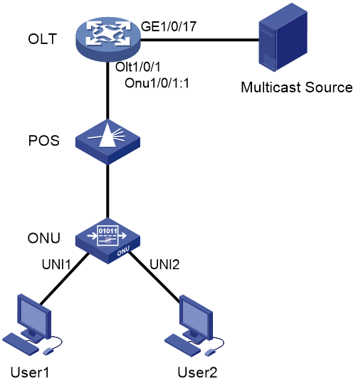
As shown in Figure 1, the ONU has been bound to ONU 1/0/1:1.
Configure multicast in IGMP snooping mode on the ONU for User 1 to access channels 225.1.2.1 through 225.1.2.255 and User 2 to access channels 225.1.3.1 through 225.1.3.255.

Configuration procedure
# Map the multicast IP addresses to multicast VLANs.
<OLT> system-view
[OLT] ftth
[OLT-ftth] multicast vlan-id 1002 ip 225.1.2.1 to 225.1.2.255
[OLT-ftth] multicast vlan-id 1003 ip 225.1.3.1 to 225.1.3.255
[OLT-ftth] quit
# Enable IGMP snooping globally.
[OLT] igmp-snooping
[OLT-igmp-snooping] quit
# Enable IGMP snooping and IGMP snooping querier and set the source IP addresses of IGMP general queries and group-specific queries to a valid IP address on the device in VLAN 1002 and VLAN 1003.
[OLT] vlan 1002
[OLT-vlan1002] igmp-snooping enable
[OLT-vlan1002] igmp-snooping querier
[OLT-vlan1002] igmp-snooping general-query source-ip 10.1.1.1
[OLT-vlan1002] igmp-snooping special-query source-ip 10.1.1.1
[OLT-vlan1002] quit
[OLT] vlan 1003
[OLT-vlan1003] igmp-snooping enable
[OLT-vlan1003] igmp-snooping querier
[OLT-vlan1003] igmp-snooping general-query source-ip 10.1.1.1
[OLT-vlan1003] igmp-snooping special-query source-ip 10.1.1.1
[OLT-vlan1003] quit
# Set the multicast mode to IGMP snooping on ONU 1/0/1:1.
[OLT] interface onu 1/0/1:1
[OLT-Onu1/0/1:1] multicast mode igmp-snooping
# Assign UNI 1 and UNI 2 of the ONU to multicast VLANs 1002 and 1003, respectively.
[OLT-Onu1/0/1:1] uni 1 multicast vlan 1002
[OLT-Onu1/0/1:1] uni 2 multicast vlan 1003
# Configure ONU 1/0/1:1 as a trunk port that permits all VLANs.
[OLT-Onu1/0/1:1] port link-type trunk
[OLT-Onu1/0/1:1] port trunk permit vlan all
# Configure UNI 1 and UNI 2 to remove the VLAN tag of downlink multicast flows.
[OLT-Onu1/0/1:1] uni 1 multicast-strip-tag enable
[OLT-Onu1/0/1:1] uni 2 multicast-strip-tag enable
[OLT-Onu1/0/1:1] quit
# Configure OLT 1/0/1 as a hybrid port, and assign it to VLAN 1002 and VLAN 1003 as a tagged member.
[OLT] interface olt 1/0/1
[OLT-Olt1/0/1] port link-type hybrid
[OLT-Olt1/0/1] port hybrid vlan 1002 1003 tagged
[OLT-Olt1/0/1] quit
# Configure GigabitEthernet 1/0/17 as a trunk port that permits VLAN 1002 and VLAN 1003.
[OLT] interface gigabitethernet 1/0/17
[OLT-GigabitEthernet1/0/17] port link-type trunk
[OLT-GigabitEthernet1/0/17] port trunk permit vlan 1002 1003
[OLT-GigabitEthernet1/0/17] quit
Multicast in multicast control mode configuration example
Network configuration
As shown in Figure 2, the ONU has been bound to ONU 1/0/1:1.
Configure multicast in multicast control mode to provide different access rights for User 1 and User 2.
· User 1 has full access to Channel 1(225.1.1.1) and 60-second preview access to Channel 2 (225.1.2.1)
· User 2 only has access to Channel 2.
Configuration procedure
# Map the multicast IP addresses to multicast VLANs.
<OLT> system-view
[OLT] ftth
[OLT-ftth] multicast vlan-id 1002 ip 225.1.1.1
[OLT-ftth] multicast vlan-id 1003 ip 225.1.2.1
[OLT-ftth] quit
# Enable IGMP snooping globally.
[OLT] igmp-snooping
[OLT-igmp-snooping] quit
# Enable IGMP snooping in VLAN 1002 and VLAN 1003.
[OLT] vlan 1002
[OLT-vlan1002] igmp-snooping enable
[OLT-vlan1002] vlan 1003
[OLT-vlan1003] igmp-snooping enable
[OLT-vlan1003] quit
# Set the multicast mode to multicast control on ONU 1/0/1:1.
[OLT] interface onu 1/0/1:1
[OLT-Onu1/0/1:1] multicast mode multicast-control
# Configure UNI 1 to allow User 1 to access Channel 1 and to preview Channel 2 for only 60 seconds.
[OLT-Onu1/0/1:1] uni 1 multicast-control multicast-address 225.1.1.1 rule permit
[OLT-Onu1/0/1:1] uni 1 multicast-control multicast-address 225.1.2.1 rule preview time-slice 1
# Configure UNI 1 to remove the VLAN tags from downlink multicast packets.
[OLT-Onu1/0/1:1] uni 1 multicast-strip-tag enable
# Configure UNI 2 to allow User 2 to access Channel 2 only.
[OLT-Onu1/0/1:1] uni 2 multicast-control multicast-address 225.1.1.1 rule deny
[OLT-Onu1/0/1:1] uni 2 multicast-control multicast-address 225.1.2.1 rule permit
# Configure UNI 2 to remove the VLAN tags from downlink multicast packets.
[OLT-Onu1/0/1:1] uni 2 multicast-strip-tag enable
# Configure ONU 1/0/1:1 as a trunk port that permits all VLANs.
[OLT-Onu1/0/1:1] port link-type trunk
[OLT-Onu1/0/1:1] port trunk permit vlan all
[OLT-Onu1/0/1:1] quit
# Configure OLT 1/0/1 as a hybrid port, and assign it to VLAN 1002 and VLAN 1003 as a tagged member.
[OLT] interface olt 1/0/1
[OLT-Olt1/0/1] port link-type hybrid
[OLT-Olt1/0/1] port hybrid vlan 1002 1003 tagged
[OLT-Olt1/0/1] quit
# Configure GigabitEthernet 1/0/17 as a trunk port that permits VLAN 1002 and VLAN 1003.
[OLT] interface GigabitEthernet 1/0/17
[OLT-GigabitEthernet1/0/17] port link-type trunk
[OLT-GigabitEthernet1/0/17] port trunk permit vlan 1002 1003
[OLT-GigabitEthernet1/0/17] quit
