- Table of Contents
- Related Documents
-
| Title | Size | Download |
|---|---|---|
| 01-EPON basics configuration | 660.43 KB |
Contents
EPON interface types and interface numbering rules
Restrictions and guidelines: OLT configuration
Setting the ONU authentication mode
Configuring the OLT operating mode
Changing the type of fiber interfaces
Setting the link type of an OLT interface
Setting the link type of an OLT interface to hybrid
Setting the link type of an OLT interface to trunk
Setting the link type of an OLT interface to access
Configuring EPON redundant interfaces
Configuring a common fiber backup group
Configuring a multidevice fiber backup group
Performing a manual master/subordinate switchover
Managing lower-level switches through AGMP
Configuration requirements and restrictions of AGMP on ONUs
Restrictions of AGMP on lower-level switches
Enabling compatibility with third-party ONUs
Enabling grant filtering on an OLT interface
Setting the processing mode for frames with an invalid source MAC address
Setting the LLID key update interval
Setting the maximum ONU-OLT RTT
Setting the timeout timer for extended OAM discovery
Setting the maximum number of E1/UNI/VoIP interfaces that can be queried by SNMP or NETCONF
Display and maintenance commands for the OLT
Example: Configuring a common fiber backup group
Example: Configuring multidevice fiber backup groups
Example: Configuring EPON redundant interfaces
Example: Configuring AGMP on an OLT
Restrictions and guidelines: ONU configuration
Enabling ONU user authentication
Restrictions and guidelines for ONU bindings
Enabling automatic ONU binding
Bulk configuring ONU interfaces through an ONU configuration template
Enabling ONU binding control on OLTs
Releasing offline ONU interfaces
Enabling automatic ONU replacement
Setting the aging timer for dynamic MAC address entries for an ONU
Configuring the management VLAN of an ONU
Setting the link type of an ONU interface and assigning the port to VLANs
Enabling user network management features on an ONU
Setting the state of the transmit power supply for transceiver modules of ONU PON interfaces
Enabling UNI count-based PON interface activation for an ONU
Enabling an ONU to send flush messages
Enabling packet statistics for an ONU
Enabling event reporting for an ONU
Enabling downlink traffic encryption for an ONU
Configuring basic settings of UNIs
Setting the MAC learning limit on a UNI
Setting the VLAN operation mode for a UNI
Configuring UNI port isolation
Configuring port mirroring on a UNI
Enabling packet statistics for a UNI
Testing the cable connected to a UNI
Configuring ONU serial interfaces
Display and maintenance commands for ONUs
ONU binding configuration example
ONU user authentication configuration example
ONU update configuration example
EPON overview
Ethernet Passive Optical Network (EPON) is a Passive Optical Network (PON) that carries Ethernet frames encapsulated in 802.3 standards. EPON is a combination of Ethernet technology and PON technology in compliance with the IEEE 802.3ah standards issued in June 2004.
EPON architecture
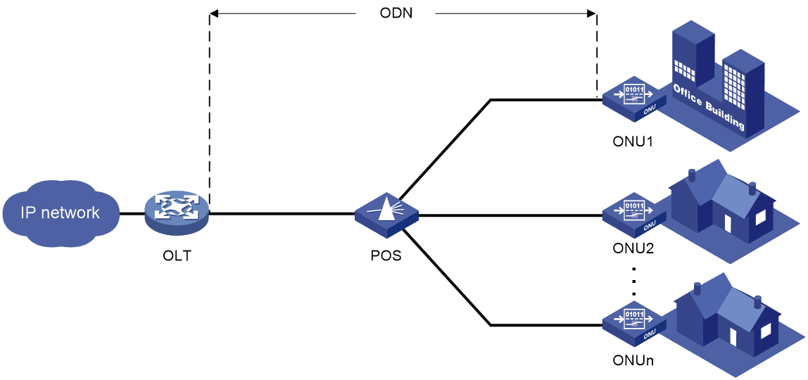
As shown in Figure 1, a typical EPON system contains optical line terminals (OLTs), optical network units (ONUs), and optical distribution networks (ODNs).
· OLT—The core device of an EPON system, located at the central office. The OLT manages ONUs in the EPON system and forwards traffic between the EPON system and the IP network.
· ONU—A device connected to customer premises equipment such as PCs, set-top boxes, and switches. Typically, ONUs are placed at customers' homes, corridors, or roadsides. ONUs forward uplink data sent by customer premises equipment (from ONU to OLT) and selectively forward downlink broadcasts sent by OLTs (from OLT to ONU).
· ODN—A network formed by optical fibers, one or multiple passive optical splitters (POSs), and other passive optical components. ODNs provide optical signal transmission paths between OLTs and ONUs. A POS can couple uplink data into a single piece of fiber and distribute downlink data to ONUs.
EPON uses the single-fiber wavelength division multiplexing (WDM) technology to implement single-fiber bidirectional transmission. WDM uses a downlink central wavelength of 1490 nm and an uplink central wavelength of 1310 nm. WDM can support a transmission distance of up to 20 km (12.43 miles).
Figure 1 Typical EPON architecture
Working mechanisms
An EPON system must complete ONU registration, extended OAM connection establishment, and bandwidth allocation before it can transmit data. EPON uses the extended OAM protocol defined by China Telecom and H3C.
ONU registration
EPON uses the following types of Multipoint Control Protocol (MPCP) messages for ONU registration:
· GATE messages, including:
¡ Discovery GATE message, broadcasted by the OLT to discover ONUs.
¡ General GATE message, unicasted by the OLT to allocate bandwidth to ONUs.
· REGISTER_REQ message.
· REGISTER message.
· REGISTER_ACK message.
Each of these messages contains a timestamp field that records the local clock at the time of packet transmission.
An ONU can register with an OLT by using its MAC address, logical ONU identifier (LOID), or LOID and LOID password. An ONU is registered by using the following workflow when its MAC address is used for registration:
1. An OLT broadcasts a discovery GATE message to notify the start time and length of the discovery timeslot to all ONUs.
2. An unregistered ONU receives the discovery GATE message and sets its local clock to be the same as the timestamp contained in the message. When the local clock reaches the start time, the ONU sends a REGISTER_REQ message to the OLT after a random delay. The REGISTER_REQ message contains the MAC address of the ONU and the local timestamp of the ONU when the message is sent.
3. The OLT receives the REGISTER_REQ message and obtains the MAC address of the ONU and ONU-OLT round trip time (RTT). The ONU-OLT RTT is mainly used for time synchronization between an OLT and ONUs.
4. The OLT parses the REGISTER_REQ message, and uses the MAC address in the message to unicast a REGISTER message to the ONU. The REGISTER message contains a logical link ID (LLID) assigned to the ONU as a unique identifier.
5. The OLT sends a general GATE message to the same ONU immediately after sending the REGISTER message.
6. The ONU receives the REGISTER message and general GATE message. Then, the ONU sends a REGISTER_ACK message in the timeslot assigned in the GATE message to notify the OLT that the REGISTER message is parsed successfully.
ONU registration is completed.
Extended OAM connection establishment
EPON supports Ethernet Operation, Administration and Maintenance (OAM) and extended OAM functions. Ethernet OAM is a network monitoring tool that operates at the data link layer. It reports link status by periodically exchanging OAMPDUs between devices for administrators to effectively manage the network. Extended OAM uses both basic OAMPDUs and extended OAMPDUs for OLTs and ONUs to establish connections and implement remote management.
An extended OAM connection is established by using the following workflow:
1. An OLT and an ONU establish a standard OAM connection.
2. The ONU reports the supported organizationally unique identifier (OUI) and extended OAM version number to the OLT.
3. The OLT identifies whether the OLT supports the reported OUI and extended OAM version number.
¡ If the OLT supports the reported OUI and extended OAM version, the extended OAM connection for the ONU is established successfully.
¡ If the reported OUI and extended OAM version are not supported, the extended OAM connection cannot be established.
Bandwidth allocation
After the extended OAM connection is established, downlink data transmission can begin. Uplink data transmission can begin only after uplink bandwidth is allocated.
An OLT allocates uplink bandwidth to an ONU by using the following workflow:
1. The OLT sends a general GATE message to assign a transmission timeslot to the ONU.
2. The ONU sends a REPORT message to report the local status information such as buffer usage to the OLT. The OLT assigns timeslots intelligently based on the local status information of ONUs.
3. The OLT receives the REPORT message, and sends a general GATE message to assign the ONU a data transmission timeslot based on the current bandwidth.
4. The ONU receives the GATE message and transmits data at the transmission start time contained in the message.
Data transmission
EPON transmits uplink data and downlink data differently.
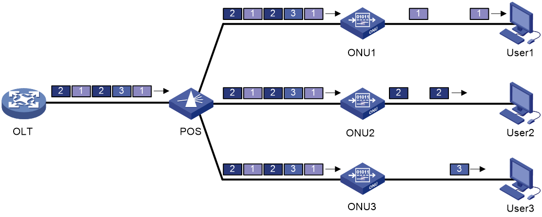
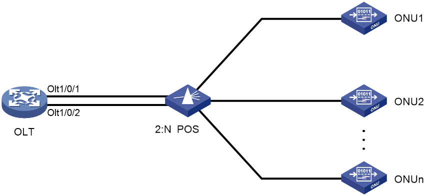
· Downlink data transmission—As shown in Figure 2, the OLT broadcasts downlink data to ONUs. Each ONU receives packets destined for it based on the LLID and drops the other packets.
Figure 2 Downlink data transmission in an EPON system
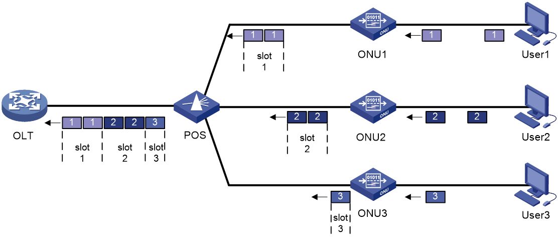
· Uplink data transmission—As shown in Figure 3, each ONU buffers the data frames received from users and sends the frames at the full wire-speed when the timeslot for the ONU arrives.
EPON uses the Time Division Multiple Access (TDMA) technology to transmit uplink data. This technology ensures that one optical fiber between the OLT and the POS can transmit data signals from multiple ONUs to the OLT without signal interference.
Figure 3 Uplink data transmission in an EPON system
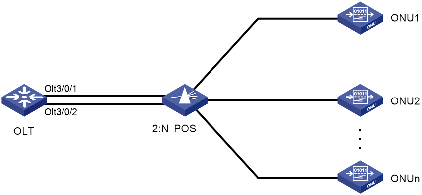
EPON interface types and interface numbering rules
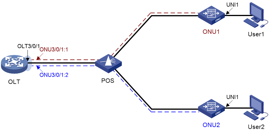
As shown in Figure 4, EPON defines the following interface types:
· OLT interface—A physical ONU-facing interface on an OLT. Each OLT interface on an EPON card can be connected to an EPON network.
OLT interfaces are numbered in the format of EPON card slot number/subcard slot number/OLT interface number, for example, OLT 3/0/1.
· ONU interface—A virtual interface created on an OLT interface.
ONU interfaces are numbered in the format of EPON card slot number/subcard slot number/OLT interface number:ONU interface number, for example, ONU 3/0/1:1.
Each ONU interface corresponds to a physical ONU. The configuration performed in ONU interface view takes effect on the ONU bound to the ONU interface. An ONU interface can identify an ONU only after the interface is bound to the ONU.
· UNI—User network interface, a physical user-facing interface on an ONU.
UNIs can be remotely configured and managed by executing commands in ONU interface view.
Figure 4 EPON interface types and interface numbers
EPON redundant backup
To ensure high availability for OLTs in the EPON system, you can add two OLT interfaces to an ROLT interface or OLT fiber backup group to implement redundant backup between OLT interfaces.
The OLT fiber backup group and the ROLT interface cannot be both configured.
EPON redundant interface
Redundant interface numbering rules
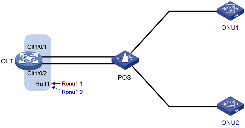
As shown in Figure 5, EPON redundant interfaces include the following types:
· ROLT—Redundant OLT interface, which is formed by binding two OLT interfaces on an OLT. Then, the two OLT interfaces can redundantly back up each other to improve the link reliability.
An ROLT interface number has only one tier, for example, ROLT 1.
· RONU—Redundant ONU interface, which is a Layer 2 logical interface created on an ROLT interface to connect an ONU.
An RONU interface is numbered in the format of ROLT interface number:RONU interface number, for example, RONU 1:1.
The configuration made in RONU interface view is applied to the ONU accessing the OLT through the RONU interface. An RONU interface is significant only when an ONU is bound to the RONU interface.
Figure 5 EPON redundant backup model
Member port state
Member ports in an ROLT interface can be in one of the following states:
· Active—A port in this state can send and receive packets. A port in this state is called an active port.
· Inactive—A port in this state cannot send or receive packets.
Determining the member port state
At any time, only one member port in an ROLT interface can be in the active state.
· When both member ports are physically up, the member port with a higher priority is active, and the other is inactive. The member port priority can be configured at the CLI.
· When the active port goes down physically, the inactive port will be automatically activated and take over to implement backup between member ports.
OLT fiber backup group
A fiber backup group can contain two OLT interfaces. In normal conditions, only the master port can forward traffic. When the system fails (for example, the trunk fiber is disconnected or the OLT interface goes down), master/subordinate switchover automatically occurs between the two member ports in the group.
OLT fiber backup groups include two types, common and multidevice.
Common fiber backup group
As shown in Figure 6, the OLT interfaces that back up each other are on the same OLT.
In a common fiber backup group, you can manually perform master/subordinate switchover between the two member ports.
Figure 6 Common fiber backup group
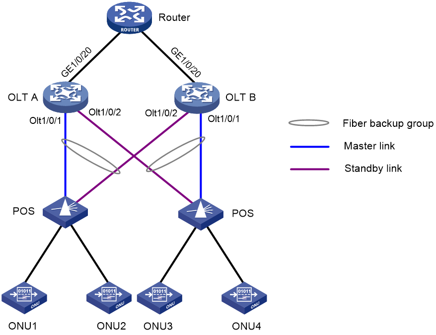
Multidevice fiber backup group
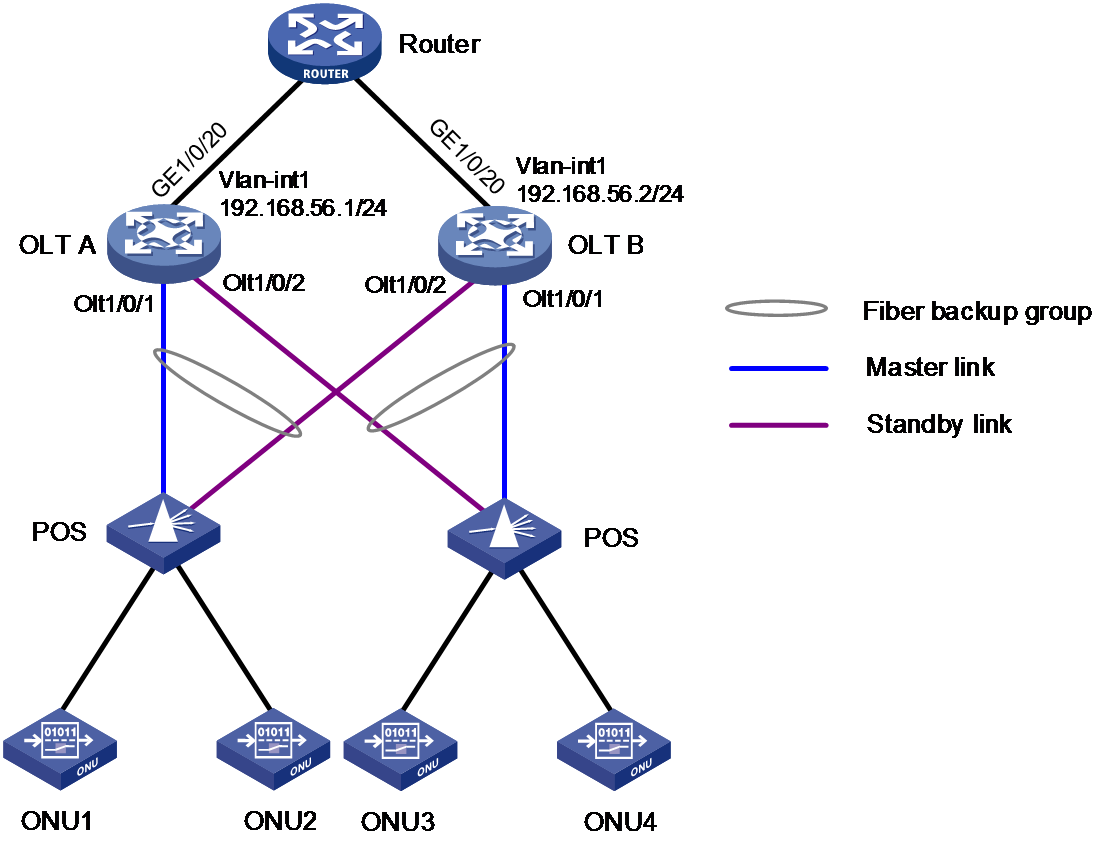
As shown in Figure 7, the OLT interfaces that back up each other are on different OLTs. The two OLTs synchronize data by using TCP connections.
Figure 7 Multidevice fiber backup group
Configuring an OLT
Restrictions and guidelines: OLT configuration
This section lists only OLT tasks. For non-EPON features supported by the device, see "Appendix Support for non-EPON features."
EPON is supported only on the default MDC. For more information about MDCs, see Virtual Technologies Configuration Guide.
The device supports the following EPON cards:
· 10G-EPON: LSQM1XPT12TSFD0 and LSQM2XPT12TSFD0 interface cards.
10G-EPON cards support the following types of ONUs:
¡ 1G ONU: The downlink bandwidth and uplink bandwidth of EPON interfaces of the ONU are both 1 Gbps.
¡ 10G/1G ONU: The downlink bandwidth and uplink bandwidth of EPON interfaces of the ONU are both 10 Gbps and 1 Gbps, respectively.
¡ 10G/10G ONU: The downlink bandwidth and uplink bandwidth of EPON interfaces of the ONU are both 10 Gbps.
· 1G-EPON cards:
¡ LSQM1PT8TSSC0 interface card.
¡ LSQM1PT24TSSC0 interface card.
1G-EPON cards support only 1G ONUs.
On a 10G-EPON card, the total downlink bandwidth and the total uplink bandwidth of all 1G ONUs connected to each OLT interface cannot exceed 1 Gbps separately.
The mac-address max-mac-count command in VLAN view, which configures the maximum number of MAC address entries that can be learned in a VLAN, does not take effect on EPON cards.
OLT tasks at a glance
All OLT configuration tasks are optional.
To configure an OLT, perform the following tasks:
· Setting the ONU authentication mode
· Configuring the OLT operating mode
· Changing the type of fiber interfaces
· Ensuring high reliability for OLTs in the EPON system
Choose one of the following tasks:
¡ Configuring EPON redundant interfaces
· Managing lower-level switches through AGMP
· Setting the link type of an OLT interface
· Enabling compatibility with third-party ONUs
· Enabling grant filtering on an OLT interface
Perform this task to ensure correct data transmission.
· Setting the processing mode for frames with an invalid source MAC address
· Tuning EPON system parameters
¡ Setting the LLID key update interval
¡ Setting the maximum ONU-OLT RTT
¡ Setting the timeout timer for extended OAM discovery
¡ Setting the maximum number of E1/UNI/VoIP interfaces that can be queried by SNMP or NETCONF
Setting the ONU authentication mode
About the ONU authentication mode
An OLT supports the following ONU authentication modes:
· MAC mode—Authenticates ONUs based on the MAC address.
· LOID mode—Authenticates ONUs based on the LOID.
· LOID-password mode—Authenticates ONUs based on the LOID and LOID password.
Restrictions and guidelines
If you configure this feature in interface view, the configuration takes effect only on the corresponding interface. If you configure this feature in FTTH view, the configuration takes effect on all ROLT interfaces and all OLT interfaces that have not been assigned to ROLT interfaces. An OLT interface or ROLT interface preferentially uses the interface-specific ONU authentication mode. If no interface-specific ONU authentication mode is available, the OLT interface or ROLT interface uses the ONU authentication mode configured in FTTH view.
You can configure multiple ONU authentication mode settings. The LOID mode and the LOID-password mode are mutually exclusive.
Configuration procedure
|
Step |
Command |
Remarks |
|
1. Enter system view. |
system-view |
N/A |
|
2. Enter FTTH view, OLT interface view, or ROLT interface view. |
· Enter FTTH view: · Enter OLT interface view: · Enter ROLT interface view: |
N/A |
|
3. Set the ONU authentication mode. |
authentication-mode { mac | loid | loid-password } * |
By default, an OLT interface uses the MAC mode for ONU authentication. |
Configuring the OLT operating mode
About OLT operating modes
10G-EPON cards support the following OLT operating modes:
· 64-ONU mode—Each OLT interface supports creating up to 64 ONU interfaces.
· 128-ONU mode—Each OLT interface supports creating up to 128 ONU interfaces.
Restrictions and guidelines
After you change the OLT operating mode for a slot, you must reboot the slot or the whole device to make the OLT operating mode change take effect.
· If the slot is rebooted, all OLT interfaces in the slot are restored to the default settings, and the ONU interfaces created on the OLT interfaces are deleted.
· If the whole device is rebooted and the running configuration is saved, ONU interfaces numbered from 1 to 64 and OLT interfaces are not affected. When the OLT operating mode is changed from 128-ONU to 64-ONU, ONU interfaces numbered more than 64 are deleted.
Configuration procedure
|
Step |
Command |
Remarks |
|
1. Enter system view. |
system-view |
N/A |
|
2. Enter FTTH view. |
ftth |
N/A |
|
3. Set the OLT operating mode for the specified slot. |
· In standalone mode: · In IRF mode: |
By default, the OLT operating mode is 64-ONU. |
Changing the type of fiber interfaces
About changing the fiber interface type
You can configure the EPON fiber interfaces on the LSQM1PT24TSSC0 interface card as OLT interfaces or GigabitEthernet interfaces.
Restrictions and guidelines
The fiber interfaces on the LSQM1PT24TSSC0 interface card are grouped by interface number in order, starting from 1. Each group contains four interfaces. To change the type of an interface in a group, you must change the type of all the four interfaces in the group. For the interface type change to take effect, reboot the interface card.
If you change the type of an interface, the system automatically removes the original interface and then creates the target interface with the same number as the original interface.
When you use a GigabitEthernet interface that is changed from an OLT interface, follow these restrictions and guidelines:
· The interface does not support jumbo frames larger than 2043 bytes. As a best practice, set the permitted jumbo frame length of the interface to 2043 bytes or a smaller value by using the jumboframe enable command.
· The interface does not support the following commands in Interface Command Reference:
¡ duplex
¡ eee enable
¡ flow-control
¡ flow-control receive enable
¡ loopback
¡ mdix-mode
¡ port up-mode
¡ speed
· The interface does not support a 100-Mbps optical transceiver module.
· For the peer interface to come up, you must configure it to work in full duplex mode and set its speed to 1000 Mbps.
· After changing the type of an interface, you must first execute the save command to save the current configuration before rebooting the interface card hosting the interface.
· The interface does not support IPv6 services.
· The interface does not support 802.1X or Ethernet OAM. For more information, see Security Configuration Guide and High Availability Configuration Guide.
Configuration procedure
|
Step |
Command |
Remarks |
|
1. Enter system view. |
system-view |
N/A |
|
2. Enter interface range view. |
· Enter OLT interface range view: · Enter Layer 2/Layer 3 GigabitEthernet
interface range view: |
N/A |
|
3. Change the type of the interfaces. |
· Change the OLT interfaces to GigabitEthernet
interfaces: · Change the GigabitEthernet interfaces to OLT
interfaces: |
By default, a GigabitEthernet interface changed from an OLT interface is in Layer 2 mode. |
Setting the link type of an OLT interface
Restrictions and guidelines
You can set the link type of an OLT interface to hybrid, trunk, or access. For more information about port link types, see VLAN configuration in Layer 2—LAN Switching Configuration Guide.
The downlink packets of an OLT interface of the access type can only be broadcast. As a best practice, do not set the link type of an OLT interface to access.
As a best practice, configure hybrid OLT interfaces on 10G-EPON cards as tagged members of VLANs by using the port hybrid vlan vlan-id-list tagged command. If these interfaces are configured as untagged members of VLANs, the downlink packets of these interfaces can only be broadcast.
To change the link type of an interface from trunk to hybrid or vice versa, first set the link type to access.
An ROLT interface also supports the link type configuration and can synchronize the configuration to its member ports. This section describes only the OLT interface configuration.
Setting the link type of an OLT interface to hybrid
Restrictions and guidelines
To enable a hybrid port to transmit packets from its PVID, you must assign the hybrid port to the PVID by using the port hybrid vlan command.
Configuration procedure
|
Step |
Command |
Remarks |
|
1. Enter system view. |
system-view |
N/A |
|
2. Enter OLT interface view. |
interface olt interface-number |
N/A |
|
3. Set the link type of the OLT interface to hybrid. |
port link-type hybrid |
By default, the link type of an OLT interface is hybrid. |
|
4. Assign the OLT interface to VLANs as a tagged or untagged member. |
port hybrid vlan vlan-id-list { tagged | untagged } |
By default, an OLT interface is an untagged member of VLAN 1. Make sure the specified VLANs have been created. |
|
5. (Optional.) Set the PVID of the OLT interface. |
port hybrid pvid vlan vlan-id |
By default, the PVID of an OLT interface is VLAN 1. |
Setting the link type of an OLT interface to trunk
Restrictions and guidelines
To enable a trunk port to transmit packets from its PVID, you must assign the trunk port to the PVID by using the port trunk permit vlan command.
Configuration procedure
|
Step |
Command |
Remarks |
|
1. Enter system view. |
system-view |
N/A |
|
2. Enter OLT interface view. |
interface olt interface-number |
N/A |
|
3. Set the link type of the OLT interface to trunk. |
port link-type trunk |
By default, the link type of an OLT interface is hybrid. |
|
4. Assign the trunk port to VLANs. |
port trunk permit vlan { vlan-id-list | all } |
By default, a trunk port allows packets only from VLAN 1 to pass through. |
|
5. (Optional.) Set the PVID of the trunk port. |
port trunk pvid vlan vlan-id |
By default, the PVID of a trunk port is VLAN 1. |
Setting the link type of an OLT interface to access
Restrictions and guidelines
After you set the link type of an OLT interface to access, you must set the link type to access for the PON port connecting the ONU to the OLT interface and assign the PON port to the same VLAN as the OLT interface.
Configuration procedure
|
Step |
Command |
Remarks |
|
1. Enter system view. |
system-view |
N/A |
|
2. Enter OLT interface view. |
interface olt interface-number |
N/A |
|
3. Set the link type of the OLT interface to access. |
port link-type access |
By default, the link type of an OLT interface is hybrid. |
|
4. Assign the access port to a VLAN. |
port access vlan vlan-id |
By default, all access ports belong to VLAN 1. Make sure the specified VLAN already exists. |
Configuring EPON redundant interfaces
Restrictions and guidelines
Restrictions and guidelines for cooperation with other features
An OLT interface assigned to a fiber backup group or configured with the ONU authentication mode cannot be assigned to an ROLT interface. An OLT interface assigned to an ROLT interface cannot be assigned to a fiber backup group or configured with the ONU authentication mode.
Restrictions and guidelines for ROLT interface configuration
When you assign member ports to an ROLT interface, follow these restrictions and guidelines:
· An ROLT interface can contain only two member ports and the member ports must have different priorities.
· An OLT interface can be assigned to only one ROLT interface.
· To assign an OLT interface to an ROLT interface, make sure the OLT interface has the same attribute configurations as the ROLT interface. The attribute configurations cannot be modified for an OLT interface that has been assigned to an ROLT interface.
Attribute configurations include port isolation, VLAN mapping, QinQ, and port-based VLAN configurations.
To ensure correct traffic forwarding after active port switchover, make sure the two member ports use the same type of transceiver models and are configured with the same speed.
To ensure correct active port switchover, make sure the two member ports are both on 10G-EPON cards or 1G-EPON cards.
Active port switchover triggered through modifying the member port priorities takes more than 30 seconds.
Restrictions and guidelines for RONU interface configuration
When you assign a member port to or remove a member port from an ROLT interface, the RONU interfaces on the ROLT interface will go down and then come up.
Manually shutting down an ROLT interface does not change the status of the ONUs attached to the RONU interfaces on the ROLT interface.
When an ONU is bound to an RONU interface, the ONU actually communicates with the active member port in the ROLT interface where the RONU interface is created. Therefore, an ONU bound to an RONU interface can register with an OLT only when the ROLT interface has member ports.
For more information about binding an ONU to an RONU interface, see "Configuring ONU bindings."
Configuration procedure
|
Step |
Command |
Remarks |
|
1. Enter system view. |
system-view |
N/A |
|
2. Create an ROLT interface and enter its view, or enter the view of an existing ROLT interface. |
interface rolt interface-number |
N/A |
|
3. Assign a member port to the ROLT interface. |
member interface olt interface-number priority priority |
By default, an ROLT interface does not have member ports. |
|
4. Create an RONU interface. |
using onu interface-number |
By default, no RONU interface exists on an ROLT interface. To enter the view of an RONU interface, execute the interface ronu command. |
|
5. (Optional.) Bring up the ROLT interface. |
undo shutdown |
By default, an ROLT interface is not manually shut down. |
Configuring fiber backup
Restrictions and guidelines
Before you delete a fiber backup group, make sure all OLT interfaces have been removed from the group.
To ensure correct traffic forwarding after switchovers, make sure the OLT interfaces in a fiber backup group have the same settings in OLT interface view and ONU configuration.
An OLT interface can be assigned to only one fiber backup group.
Select a fiber backup group (common or multidevice) as needed according to the OLT deployment conditions.
Configuring a common fiber backup group
|
Step |
Command |
Remarks |
|
1. Enter system view. |
system-view |
N/A |
|
2. Enter FTTH view. |
ftth |
N/A |
|
3. Create a common fiber backup group and enter its view. |
fiber-backup group group-number |
N/A |
|
4. Assign an OLT interface to the fiber backup group. |
· Assign an OLT interface to the fiber
backup group in fiber backup group view. · Assign an OLT interface to the fiber backup
group in OLT interface view. |
By default, an OLT interface is not assigned to any fiber backup group. Perform this task twice to add two OLT interfaces to the fiber backup group. The first OLT interface assigned to the fiber backup group is the master port, and the second OLT interface assigned is the subordinate port. |
Configuring a multidevice fiber backup group
Restrictions and guidelines
Perform this task on two OLTs separately.
For a multidevice fiber backup group to operate properly, make sure the local IP and peer IP specified in the fiber-backup tcp command can reach each other at Layer 3.
Configuration procedure
|
1. Enter system view. |
system-view |
N/A |
|
2. Enter FTTH view. |
ftth |
N/A |
|
3. Configure TCP connection parameters for multidevice fiber backup groups. |
fiber-backup tcp local-ip local-ip-address peer-ip peer-ip-address |
By default, no TCP connection parameters are configured for multidevice fiber backup groups. |
|
4. Create a multidevice fiber backup group and enter its view. |
fiber-backup group group-number multidevice |
Make sure the group number is the same on the two OLTs. |
|
5. Configure the uplink interface for the multidevice fiber backup group. |
uplink interface interface-type interface-number |
By default, no uplink interface is configured for a multidevice fiber backup group. The uplink interface must be a Layer 2 Ethernet interface or Layer 2 aggregate interface. |
|
6. Assign an OLT interface to the fiber backup group. |
· Assign an OLT interface to the fiber
backup group in fiber backup group view. · Assign an OLT interface to the fiber backup
group in OLT interface view. |
By default, an OLT interface is not assigned to any fiber backup group. Make sure an OLT interface on an OLT is configured as the master port and an OLT interface on the other OLT is configured as the subordinate port. |
Performing a manual master/subordinate switchover
Restrictions and guidelines
This feature is supported only by common fiber backup groups.
Configuration procedure
|
Step |
Command |
Remarks |
|
1. Enter system view. |
system-view |
N/A |
|
2. Enter FTTH view. |
ftth |
N/A |
|
3. Enter fiber backup group view. |
fiber-backup group group-number |
Make sure the specified fiber backup group has been created and contains two OLT interfaces. |
|
4. Perform a manual master/subordinate switchover. |
port switch-over |
For successful command execution, use this command when the subordinate OLT interface is in Ready state. |
Managing lower-level switches through AGMP
About this task
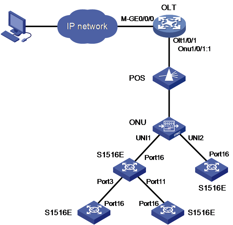
Aolynk Group Management Protocol (AGMP) is a LAN switch management protocol based on the data link layer. As shown in Figure 8, after AGMP is enabled on an OLT, you can remotely manage the Aolynk S1500E series switches in the LAN through the Web interface on the OLT.

Configuration requirements and restrictions of AGMP on ONUs
To ensure service smoothness, when you configure and manage ONUs on an OLT, you must set the VLAN operation mode to transparent mode for the UNIs on these ONUs.
You cannot remotely manage the S1500E series switches connected to the following ONUs through AGMP on the OLT.
· ONUs connected to RONU interfaces.
· ONUs connected to an OLT interface assigned to a multidevice fiber backup group.
Restrictions of AGMP on lower-level switches
AGMP on an OLT supports managing the S1500E series switches with the management LEDs on the right of the ports.
Each ONU connected to an OLT supports managing up to three levels of six cascaded S1500E series switches.
An S1500E series switch can be discovered and managed by an OLT only when the switch is connected to an ONU or an upper-level switch through its management interface. The management interface of an S1500E series switch is the last port on the switch, for example, interface 16 on an S1516E-B switch and interface 24 on an S1524E-B switch.
Procedure
|
Step |
Command |
Remarks |
|
1. Enter system view. |
system-view |
N/A |
|
2. Enter FTTH view. |
ftth |
N/A |
|
3. Enable AGMP. |
agmp enable |
By default, AGMP is disabled. |
Enabling compatibility with third-party ONUs
About compatibility with third-party ONUs
To allow non-H3C ONUs to register with an OLT, enable compatibility with third-party ONUs. If this feature is disabled, only H3C ONUs can register with the OLT.
Restrictions and guidelines
If you bind a non-H3C ONU to an ONU interface before this feature is enabled, the ONU cannot register with the OLT even if you enable this feature. For successful registration, you must perform one of the following tasks:
· Use the deregister onu command to deregister the ONU.
· Use the shutdown command to shut down the ONU interface and then use the undo shutdown command to bring it up.
Configuration procedure
|
Step |
Command |
Remarks |
|
1. Enter system view. |
system-view |
N/A |
|
2. Enter FTTH view. |
ftth |
N/A |
|
3. Enable compatibility with third-party ONUs. |
· In standalone mode: · In IRF mode: |
By default, compatibility with third-party ONUs is enabled. |
Enabling grant filtering on an OLT interface
About grant filtering
If time synchronization of an EPON system is accurate, an OLT receives packets from an ONU only within the timeslot assigned to the ONU. If the clock of an ONU is inaccurate, the ONU might send packets to the OLT in another ONU's timeslot. For correct data transmission, enable grant filtering on the OLT interface. The OLT interface will drop the packets that are transmitted in an incorrect timeslot.
Configuration procedure
|
Step |
Command |
Remarks |
|
1. Enter system view. |
system-view |
N/A |
|
2. Enter OLT interface view. |
interface olt interface-number |
N/A |
|
3. Enable grant filtering on the OLT interface. |
grant-filtering enable |
By default, grant filtering is enabled on an OLT interface. |
Setting the processing mode for frames with an invalid source MAC address
About the processing mode for frames with an invalid source MAC address
An invalid MAC address is a MAC address whose seventh bit of the first byte is 1, for example, 02-10-94-00-00-02 (the first byte is 00000010). This task sets the mode for the OLT to process a frame with an invalid source MAC address.
· Abandon mode—The OLT drops frames with an invalid source MAC address.
· Broadcast mode—The OLT forwards frames sourced from an invalid MAC address without learning the source MAC address. When the OLT receives a frame with an invalid destination MAC address, it floods the frame to all interfaces in the frame's VLAN except for the incoming interface.
· Unicast mode—The OLT forwards frames sourced from an invalid MAC address and generates a unicast MAC address entry for the invalid MAC address. The OLT uses the entry for forwarding frames destined for the invalid MAC address.
Restrictions and guidelines
The processing mode for frames with an invalid source MAC address does not affect the following interfaces:
· OLT interfaces on 10G-EPON cards.
· GE interfaces changed from EPON fiber interfaces.
Configuration procedure
|
Step |
Command |
Remarks |
|
1. Enter system view. |
system-view |
N/A |
|
2. Enter FTTH view. |
ftth |
N/A |
|
3. Set the processing mode for frames with an invalid source MAC address. |
onu invalid-address mode { abandon | broadcast | unicast } |
By default, the abandon mode is enabled for frames with an invalid source MAC address. |
Tuning EPON system parameters
Setting the LLID key update interval
About the LLID key update interval
An OLT broadcasts downlink data to ONUs. To secure user data transmission, each LLID in an EPON system uses an independent key. The OLT periodically requests ONUs to update their LLID keys. Each ONU responds with a new LLID key after it receives the LLID key update request from the OLT.
Configuration procedure
|
Step |
Command |
Remarks |
|
1. Enter system view. |
system-view |
N/A |
|
2. Enter FTTH view. |
ftth |
N/A |
|
3. Set the LLID key update interval. |
· In standalone mode: · In IRF mode: |
By default, the LLID key update interval is 10 seconds. |
Setting the maximum ONU-OLT RTT
About the maximum ONU-OLT RTT
You can adjust the scale of an EPON system by setting the maximum ONU-OLT RTT on the OLT. An ONU cannot be registered if its RTT is greater than the maximum ONU-OLT RTT set on the OLT.
An ONU distant from the OLT suffers high optical power attenuation. To prevent distant ONUs from registering with the EPON system, set a short maximum ONU-OLT RTT.
The unit of RTT is time quantum (TQ). 1 TQ is equal to 16 ns, the time for transmitting two bytes of data at 1 Gbps.
Restrictions and guidelines
Make sure you are fully aware of the impact of this task when you perform it on a live network.
The maximum ONU-OLT RTT takes effect only on unregistered ONUs.
Configuration procedure
|
Step |
Command |
Remarks |
|
1. Enter system view. |
system-view |
N/A |
|
2. Enter OLT interface view. |
interface olt interface-number |
N/A |
|
3. Set the maximum ONU-OLT RTT. |
max-rtt value |
By default, the maximum ONU-OLT RTT is 15000 TQ. |
Setting the timeout timer for extended OAM discovery
About the timeout timer for extended OAM discovery
The timeout timer for extended OAM discovery determines the timeout period for extended OAM messages during extended OAM discovery.
As a best practice, use the default setting for this timer. Increase this timer on the card that hosts an OLT interface if an ONU connected to the OLT and bound to an ONU interface remains down.
Configuration procedure
|
Step |
Command |
Remarks |
|
1. Enter system view. |
system-view |
N/A |
|
2. Enter FTTH view. |
ftth |
N/A |
|
3. Set the timeout timer for extended OAM discovery. |
· In standalone mode: · In IRF mode: |
The unit for the value argument is 100 milliseconds. By default, the timeout timer for extended OAM discovery is 3 seconds. |
Setting the maximum number of E1/UNI/VoIP interfaces that can be queried by SNMP or NETCONF
About this task
The device supports querying the interface information on ONUs through SNMP or NETCONF and reporting the query result to the NMS through SNMP or NETCONF. When a large number of ONUs exist or ONUs have a large number of interfaces, the querying and reporting operations consume a large number of system resources. By decreasing the maximum number of ONU E1/UNI/VoIP interfaces on offline OUs that can be queried by SNMP or NETCONF, you can reduce the resource consumption of the device.
Restrictions and guidelines
This feature is only for administrators. As a best practice, do not use this feature as a common user.
This feature applies to all ONU interfaces of all OLT interfaces, and takes effect only on offline ONU interfaces of ONUs.
Configuration procedure
|
Step |
Command |
Remarks |
|
1. Enter system view. |
system-view |
N/A |
|
2. Enter FTTH view. |
ftth |
N/A |
|
3. Set the maximum number of E1/UNI/VoIP interfaces that can be queried by SNMP or NETCONF. |
onu snmp port-limit { e1 e1-count | uni uni-count | voip voip-count }* |
By default: · The maximum number of UNIs that can be queried by SNMP or NETCONF is 4. · The maximum number of E1 or VoIP interfaces that can be queried by SNMP or NETCONF is 0. |
Configuring EPON alarms
About alarms on OLT interfaces
To report critical EPON events, enable alarms for EPON. For EPON event alarms to be sent correctly, you must also configure SNMP on the device. For more information about SNMP configuration, see Network Management and Monitoring Configuration Guide.
Restrictions and guidelines
If you enable alarms in OLT interface view, the configuration takes effect only on the OLT interface. If you enable alarms in FTTH view, the configuration takes effect on all OLT interfaces.
If you configure alarms in both OLT interface view and FTTH view, the most recent configuration takes effect on the OLT interface.
To view alarm settings, use the display this command in FTTH view or OLT interface view.
Configuration procedure
|
Step |
Command |
Remarks |
|
1. Enter system view. |
system-view |
N/A |
|
2. Enter FTTH view. |
ftth |
N/A |
|
3. Enable alarm monitoring. |
monitor enable |
By default, alarm monitoring is enabled. |
|
4. (Optional.) Set the alarm monitoring interval. |
timer monitor seconds |
By default, the alarm monitoring interval is 80 seconds. |
|
5. Return to system view. |
quit |
N/A |
|
6. Enter FTTH view or OLT interface view. |
· Enter FTTH view: · Enter OLT interface view: |
N/A |
|
7. Enable the device fatal error alarm. |
alarm device-fatal-error enable |
By default, the device fatal error alarm is enabled. This alarm is sent if an error that causes system unavailability occurs, such as memory leak and high memory usage. |
|
8. Enable the critical event alarm. |
alarm oam critical-event enable |
By default, the critical event alarm is enabled. This alarm is sent if the local link fault or dying gasp alarm is sent. |
|
9. Enable the dying gasp alarm. |
alarm oam dying-gasp enable |
By default, the dying gasp alarm is enabled. This alarm is sent if an irrecoverable error occurs, such as a system error and a data loading error. |
|
10. Enable the local link fault alarm. |
alarm oam local-link-fault enable |
By default, the local link fault alarm is enabled. This alarm is sent if a fault occurs in the inbound direction on the OLT. |
|
11. Enable the ONU laser-always-on alarm. |
alarm onu-laser always-on enable [ action power-off ] |
By default, the ONU laser-always-on alarm is enabled. This alarm is sent if an ONU keeps sending optical signals for a long period of time. With the action power-off keyword specified, the OLT generates laser-always-on alarms and powers off the Tx power (Tx power for the transceiver module of a PON port) of an ONU when the OLT detects laser-always-on events on the ONU. |
|
12. Enable the ONU over limit alarm. |
alarm onu-over-limit enable |
By default, the ONU over limit alarm is enabled. This alarm is sent if the number of ONUs connected to the OLT reaches the upper limit. |
|
13. Enable the registration error alarm. |
alarm registration-error enable |
By default, the registration error alarm is enabled. This alarm is sent if an error occur during ONU registration. |
Display and maintenance commands for the OLT
Execute display commands in any view.
|
Task |
Command |
|
Display EPON alarm information. |
display epon alarm history [ interface interface-type interface-number ] [ count number ] [ from start-time ] [ to end-time ] |
|
Display EPON alarm statistics. |
display epon alarm statistics [ interface interface-type interface-number ] [ from start-time ] [ to end-time ] |
|
Display ONU authentication mode settings. |
display epon authentication-mode [ interface interface-type interface-number ] |
|
Display information about fiber backup groups. |
display epon fiber-backup group { group-number | all } |
|
Display OAM information for an ONU. |
display epon oam interface interface-type interface-number |
|
Display ONU registration and deregistration records for an ONU interface. |
display epon onu-event interface interface-type interface-number |
|
Display optical parameters for an OLT interface. |
display epon optics-parameters interface interface-type interface-number |
|
(In standalone mode.) Display EPON system parameters. |
display epon parameter slot slot-number |
|
(In IRF mode.) Display EPON system parameters. |
display epon parameter chassis chassis-number slot slot-number |
|
Display packet error rates on an ONU. |
display epon statistics interface interface-type interface-number |
|
Display version information for an OLT or ONU. |
display epon version interface interface-type interface-number |
|
Display the operating mode of an OLT or ONU. |
display epon workmode interface interface-type interface-number |
|
Display information about OLT interfaces, ONU interfaces, ROLT interfaces, or RONU interfaces. |
display interface [ interface-type [ interface-number ] ] [ brief [ description | down ] ] |
|
Display packets statistics on OLT interfaces. |
· In standalone mode: · In IRF mode: |
|
Display information about member ports of an ROLT interface. |
display rolt interface rolt interface-number |
OLT configuration examples
Example: Configuring a common fiber backup group
Network configuration
As shown in Figure 9, assign the two OLT interfaces to a common fiber backup group.
Configuration procedure
# Create fiber backup group 1.
<OLT> system-view
[OLT] ftth
[OLT-ftth] fiber-backup group 1
# Assign OLT 1/0/1 and OLT 1/0/2 to the fiber backup group in sequence. OLT 1/0/1 is the master port, and OLT 1/0/2 is the subordinate port.
[OLT-fiber-group1] member olt1/0/1
[OLT-fiber-group1] member olt1/0/2
[OLT-fiber-group1] display epon fiber-backup group 1
Fiber backup group 1 information:
Member Role State
OLT1/0/1 Master Active
OLT1/0/2 Standby Ready
Verifying the configuration
# Perform a master/subordinate switchover, and verify that OLT 1/0/2 becomes the master port.
[OLT-fiber-group1] port switch-over
[OLT-fiber-group1] display epon fiber-backup group 1
Fiber backup group 1 information:
Member Role State
OLT1/0/2 Master Active
OLT1/0/1 Standby Ready
# Shut down OLT 1/0/2, and verify that OLT 1/0/1 becomes the master port.
[OLT-fiber-group1] quit
[OLT] interface olt1/0/2
[OLT-Olt1/0/2] shutdown
[OLT-Olt1/0/2] display epon fiber-backup group 1
Fiber backup group 1 information:
Member Role State
OLT1/0/1 Master Active
OLT1/0/2 Standby Other
Example: Configuring multidevice fiber backup groups
Network configuration
As shown in Figure 10, traffic from ONUs is transmitted to Router through OLT A and OLT B.
Create two multidevice fiber backup groups on OLT A and OLT B separately. In fiber backup groups numbered the same, the two OLT interfaces back up each other.
The two OLTs synchronize data by using uplink interfaces and TCP connections.
Configuration procedure
1. Configure VLAN interfaces and IP addresses
Configure IP addresses and masks for VLAN interfaces according to the network diagram. Make sure OLTs can reach each other at Layer 3. (Details not shown.)
2. Configure OLT A
# Configure TCP connection parameters for multidevice fiber backup groups. The local device IP is 192.168.56.1, and the peer device IP is 192.168.56.2.
<OLT A> system-view
[OLT A] ftth
[OLT A-ftth] fiber-backup tcp local-ip 192.168.56.1 peer-ip 192.168.56.2
# Create multidevice fiber backup group 1. Configure Layer 2 Ethernet interface GigabitEthernet 1/0/20 as the uplink interface of the fiber backup group. Assign OLT 1/0/1 to the fiber backup group as the master port.
[OLT A-ftth] fiber-backup group 1 multidevice
[OLT A-fiber-group1] uplink interface gigabitethernet 1/0/20
[OLT A-fiber-group1] member olt 1/0/1 master
[OLT A-fiber-group1] quit
# Create multidevice fiber backup group 2. Configure Layer 2 Ethernet interface GigabitEthernet 1/0/20 as the uplink interface of the fiber backup group. Assign OLT 1/0/2 to the fiber backup group as the subordinate port.
[OLT A-ftth] fiber-backup group 2 multidevice
[OLT A-fiber-group2] uplink interface gigabitethernet 1/0/20
[OLT A-fiber-group2] member olt 1/0/2 standby
[OLT A-fiber-group2] quit
3. Configure OLT B
# Configure TCP connection parameters for multidevice fiber backup groups.
<OLT B> system-view
[OLT B] ftth
[OLT B-ftth] fiber-backup tcp local-ip 192.168.56.2 peer-ip 192.168.56.1
# Create multidevice fiber backup group 1. Configure Layer 2 Ethernet interface GigabitEthernet 1/0/20 as the uplink interface of the fiber backup group. Assign OLT 1/0/2 to the fiber backup group as the subordinate port.
[OLT B-ftth] fiber-backup group 1 multidevice
[OLT B-fiber-group1] uplink interface gigabitethernet 1/0/20
[OLT B-fiber-group1] member olt 1/0/2 standby
[OLT B-fiber-group1] quit
# Create multidevice fiber backup group 2. Configure Layer 2 Ethernet interface GigabitEthernet 1/0/20 as the uplink interface of the backup group. Assign OLT 1/0/1 to the fiber backup group as the master port.
[OLT B-ftth] fiber-backup group 2 multidevice
[OLT B-fiber-group2] uplink interface gigabitethernet 1/0/20
[OLT B-fiber-group2] member olt 1/0/1 master
[OLT B-fiber-group2] quit
Verifying the configuration
This section takes multidevice fiber backup group 1 as an example. Display information about the fiber backup group on the two OLTs.
# Display information about fiber backup group 1 on OLT A.
<OLT A> display epon fiber-backup group 1
Fiber backup group 1 information:
Member Role State
OLT1/0/1 Master Active
Uplink interface: GigabitEthernet1/0/20
The output shows that the master port OLT 1/0/1 is in active state.
# Display information about fiber backup group 1 on OLT B.
<OLT B> display epon fiber-backup group 1
Fiber backup group 1 information:
Member Role State
OLT1/0/2 Standby Ready
Uplink interface: GigabitEthernet1/0/20
The output shows that the master port OLT 1/0/2 is in ready state.
Example: Configuring EPON redundant interfaces
Network configuration
Create ROLT interface 1 on the OLT and assign member ports OLT /0/1 and OLT 1/0/2 to implement redundant backup between the OLT interfaces.
Figure 11 Network diagram

Configuration procedure
# Create ROLT interface 1 and enter its view.
<Sysname> system-view
[Sysname] interface rolt 1
# Assign OLT 1/0/1 to ROLT interface 1 and specify the priority as 100. Assign OLT 1/0/2 to ROLT interface 1 and specify the priority as 50. OLT 1/0/1 will become active preferentially.
[Sysname-Rolt1] member interface olt 1/0/1 priority 100
[Sysname-Rolt1] member interface olt 1/0/2 priority 50
[Sysname-Rolt1] quit
# Enable auto ONU binding on slot 1. Then, the device will automatically create RONU interfaces according to the number of ONUs to be bound.
[Sysname] ftth
[Sysname-ftth] onu bind auto slot 1
Verifying the configuration
# Display information about interface ROLT 1.
<Sysname> display rolt interface rolt 1
Rolt1:
Member Priority Forwarding status Presence status
Olt1/0/1 100 Active Normal
Olt1/0/2 50 Inactive Normal
The output shows that OLT 1/0/1 is active.
# Display information about ONUs on ROLT 1.
<Sysname> display onu interface rolt 1
MAC LOID LLID Dist(M) Port Mode
l/Version Sft/Epm State Aging
000f-e200-0031 N/A N/A Ronu1:1 N/A
N/A Offline N/A
000f-e200-3749 N/A N/A Ronu1:2 N/A
N/A Offline N/A
The output shows that two ONUs have been bound to RONU interfaces on ROLT 1.
Example: Configuring AGMP on an OLT
Network configuration
As shown in Figure 12, you can remotely manage S1500E series switches in the LAN through AGMP on the OLT.
Configure an IP address for the management interface of the OLT at the CLI. Then, you can use log in to the Web interface of AGMP through this IP address.
Procedure
1. Log in to the OLT through the console port on a user PC, and configure the IP address as 172.7.102.106 for the management interface of the OLT.
<OLT> system-view
[OLT] interface m-gigabitethernet 0/0/0
[OLT-M-GigabitEthernet0/0/0] ip address 172.7.102.106 8
[OLT-M-GigabitEthernet0/0/0] quit
2. Configure VLANs:
# Create VLAN 100 on the OLT.
[OLT] vlan 100
[OLT-vlan100] quit
# Assign OLT 1/0/1 to VLAN 100.
[OLT] interface olt 1/0/1
[OLT-Olt1/0/1] port hybrid vlan 100 tagged
# Create ONU interface ONU 1/0/1:1 on OLT 1/0/1.
[OLT-Olt1/0/1] using onu 1
[OLT-Olt1/0/1] quit
3. Remotely configure the ONU:
# Configure ONU 1/0/1:1 as a trunk port and assign it to VLAN 100. Configure the PVID of the interface as VLAN 100.
[OLT] interface onu1/0/1:1
[OLT-Onu1/0/1:1] port link-type trunk
[OLT-Onu1/0/1:1] port trunk permit vlan 100
[OLT-Onu1/0/1:1] port trunk pvid vlan 100
# Bind the MAC address of the ONU to the ONU interface on the OLT.
[OLT-Onu1/0/1:1] bind onu-id 586a-b1ea-9215
# Configure the VLAN operation mode of UNI 1 on the ONU as transparent. (The default configuration. You do not need to execute this command.)
[OLT-Onu1/0/1:1] uni 1 vlan-mode transparent
[OLT-Onu1/0/1:1] quit
4. Enable AGMP on the OLT.
[OLT] ftth
[OLT-ftth] agmp enable
[OLT-ftth] quit
5. Configure the user and permission for logging in to the Web interface:
# Create a local user named admin, and configure the password, authorized user role, and service types that can be used for the user.
[OLT] local-user admin
[OLT-luser-manage-admin] password simple h3c12345678
[OLT-luser-manage-admin] authorization-attribute user-role network-admin
[OLT-luser-manage-admin] service-type http https
[OLT-luser-manage-admin] service-type ftp
[OLT-luser-manage-admin] quit
# Enable the HTTP and HTTPS services.
[OLT] ip http enable
[OLT] ip https enable
6. Log in to the Web interface:
a. Open the browser, and enter IP address 172.7.102.106 in the address bar to enter the Web login interface of the OLT.
b. Enter the username and password configured previously to log in to the Web interface.
Remotely managing ONUs
Restrictions and guidelines: ONU configuration
In this section, the configuration that can be made on an ONU interface also can be made on an RONU interface. Typically, the configuration in RONU interface view is not otherwise described.
In an EPON system, support of ONUs for features depends on the ONU model and version.
This section introduces only ONU configuration tasks. For information about non-EPON features supported by ONU interfaces, see "Appendix Support for non-EPON features."
EPON is supported only on the default MDC. For more information about MDCs, see Virtual Technologies Configuration Guide.
ONU interfaces and RONU interfaces do not support ARP detection and MFF. For more information about ARP detection and MFF, see Security Configuration Guide.
ONU tasks at a glance
To remotely manage ONUs, perform the following tasks:
2. (Optional.) Enabling ONU user authentication
4. (Optional.) Bulk configuring ONU interfaces through an ONU configuration template
5. (Optional.) Enabling ONU binding control on OLTs
6. Configuring the ONU blacklist
7. Releasing offline ONU interfaces
8. (Optional.) Configuring basic ONU management features
¡ Setting the aging timer for dynamic MAC address entries for an ONU
¡ Configuring the management VLAN of an ONU
¡ Setting the link type of an ONU interface and assigning the port to VLANs
¡ Enabling user network management features on an ONU
9. (Optional.) Configuring advanced ONU management features
¡ Setting the state of the transmit power supply for transceiver modules of ONU PON interfaces
¡ Enabling UNI count-based PON interface activation for an ONU
¡ Enabling an ONU to send flush messages
¡ Enabling packet statistics for an ONU
¡ Enabling event reporting for an ONU
¡ Enabling downlink traffic encryption for an ONU
10. (Optional.) Updating and managing ONUs
11. (Optional.) Configuring UNIs
¡ Configuring basic settings of UNIs
¡ Setting the MAC learning limit on a UNI
¡ Setting the VLAN operation mode for a UNI
¡ Configuring UNI port isolation
¡ Configuring port mirroring on a UNI
¡ Enabling packet statistics for a UNI
¡ Testing the cable connected to a UNI
12. (Optional.) Configuring ONU serial interfaces
Creating ONU interfaces
About this task
ONU interfaces are used to remotely configure ONUs accessing OLT interfaces.
Restrictions and guidelines
When you use ROLT interfaces to connect ONUs, you must create RONU interfaces instead of ONU interfaces. For more information about creating RONU interfaces, see "Configuring EPON redundant interfaces."
This task is optional when ONUs are batch or automatically bound. The device can create ONU interfaces or RONU interfaces according to the number of ONUs to be bound.
Configuration procedure
|
Command |
Remarks |
|
|
1. Enter system view. |
system-view |
N/A |
|
2. Enter OLT interface view. |
interface olt interface-number |
N/A |
|
3. Create ONU interfaces. |
using onu onu-number-list |
By default, no ONU interfaces exist. |
Enabling ONU user authentication
About this task
When MAC-based automatic ONU binding is enabled, you can use this feature to authenticate ONUs. Only ONUs passing authentication can come online. This feature prevents illegal ONUs from being bound to the OLT.
With ONU user authentication enabled, an OLT will automatically obtain the MAC address of an access ONU as the username and password for authentication. You can modify the format of the username and password. You can modify other authentication parameters in the ISP domain specified for ONU user authentication. For more information about ISP domains, see AAA configuration in Security Configuration Guide.
Configuration procedure
|
Step |
Command |
Remarks |
|
1. Enter system view. |
system-view |
N/A |
|
2. Enter OLT interface view or ROLT interface view. |
· Enter OLT interface view. · Enter ROLT interface view. |
N/A |
|
3. Enable ONU authentication and specify the ISP domain used for ONU users. |
onu authentication-domain domain-name |
By default, ONU authentication is disabled on an OLT. |
|
4. Return to system view. |
quit |
N/A |
|
5. Enter FTTH view. |
ftth |
N/A |
|
6. (Optional.) Configure the account format for ONU authentication users. |
onu authentication-format mac-address { { with-hyphen | without-hyphen } | { lowercase | uppercase } }* |
By default, an OLT uses the MAC address of an ONU as the username and password for ONU authentication, and the MAC address has two hyphens and all letters in the MAC address are uppercase. |
Configuring ONU bindings
About ONU bindings
An OLT authenticates ONUs based on the MAC address, LOID, or LOID and LOID password, and denies illegal ONU access to the system. For an ONU to pass authentication and be registered, you must bind the ONU to an ONU interface or RONU interface. After the ONU passes authentication, the bound ONU interface or RONU interface comes up, and the ONU comes online.
You can bind ONUs to ONU interfaces or RONU interfaces by using the following methods:
· Binding ONUs to ONU interfaces or RONU interfaces one by one—If the EPON system contains a small number of ONUs, you can manually bind each ONU to an ONU interface or RONU interface.
· Performing batch ONU binding—If an ONU is not bound to any ONU interface or RONU interface, the ONU cannot be registered. Such an ONU is called a silent ONU. Batch ONU binding automatically binds existing silent ONUs to ONU interfaces or RONU interfaces at a time. The ONUs that join the system after batch ONU binding is performed will not be bound.
Batch ONU binding applies to a newly established EPON system that contains only legal ONUs. You can use the bind onu-id command to manually bind new ONUs after batch ONU binding is performed.
· Enabling automatic ONU binding—Automatic ONU binding automatically binds ONU interfaces or RONU interfaces to existing silent ONUs and ONUs that join the system after this feature is enabled.
Automatic ONU binding applies to an EPON system where ONUs attached to the OLT are completely trustworthy. To unbind an ONU, first use the undo onu bind auto command to disable automatic ONU binding.
When batch or automatic ONU binding is performed, if an ROLT interface exists on the device, the RONU interfaces are preferentially used to bind ONUs. When the number of ONU interfaces or RONU interfaces is insufficient, the device will automatically create such logical interfaces for ONU binding.
Restrictions and guidelines for ONU bindings
An OLT interface or ROLT interface can register a maximum of 63 ONUs.
The ONU attributes (MAC address, LOID, and LOID password) you use for ONU binding are not restricted by the ONU authentication mode set by using the authentication-mode command.
An ONU goes offline when you use the undo bind onu-id command to unbind it from its interface.
When you bind an ONU manually, follow these restrictions and guidelines:
· Only one ONU can be bound to an ONU interface or RONU interface.
· You can bind an ONU to two ONU interfaces that are on different member OLT interfaces of a fiber backup group.
Manually binding an ONU
|
Step |
Command |
Remarks |
|
1. Enter system view. |
system-view |
N/A |
|
2. Enter ONU interface view. |
interface onu interface-number |
N/A |
|
3. Bind an ONU to the ONU interface. |
bind onu-id { mac-address | loid loid | loid-password loid { cipher | simple } password } |
By default, no ONU is bound to an ONU interface. |
Performing batch ONU binding
|
Step |
Command |
Remarks |
|
1. Enter system view. |
system-view |
N/A |
|
2. Enter FTTH view. |
ftth |
N/A |
|
3. Perform batch ONU binding. |
· In standalone mode: · In IRF mode: |
By default, batch ONU binding is not performed. |
Enabling automatic ONU binding
|
Step |
Command |
Remarks |
|
1. Enter system view. |
system-view |
N/A |
|
2. Enter FTTH view. |
ftth |
N/A |
|
3. Enable automatic ONU binding. |
· In standalone mode: · In IRF mode: |
By default, automatic ONU binding is disabled. |
Bulk configuring ONU interfaces through an ONU configuration template
About this task
An ONU configuration template saves multiple commands for remotely configuring ONUs. When ONUs are bulk or automatically bound, you can apply an ONU configuration template to automatically configure the existing and newly online ONUs.
You can apply an ONU configuration template to one of the following destinations:
· Globally—Apply an ONU configuration template in FTTH view. Then, commands in the template are issued to the ONU interfaces with online ONUs on all OLT interfaces. When you create a new ONU interface, the commands in the template are automatically issued to the interface.
· OLT interface—Apply an ONU configuration template to an OLT interface. Then, commands in the template are issued to the ONU interfaces with online ONUs on this OLT interface. When you create a new ONU interface on the OLT interface, the commands in the template are automatically issued to the interface.
Restrictions and guidelines
When applying or removing an ONU configuration template, follow these restrictions and guidelines:
· You can apply an ONU configuration template either globally or to an OLT interface, but not both.
· After an ONU configuration template is applied, you cannot execute commands in the ONU configuration template. To do that, first remove the ONU configuration template.
· When an ONU configuration template is removed, the commands already issued to ONU interfaces are not withdrawn.
Configuring an ONU Configuration template
|
Step |
Command |
Remarks |
|
1. Enter system view. |
system-view |
N/A |
|
2. Create an ONU configuration template and enter its view. |
onu template template-id |
N/A |
|
3. In the ONU configuration template, execute the commands for remotely configuring ONUs. |
In ONU configuration template view, you can execute the following commands: · VLAN commands: ¡ port access vlan ¡ port link-type ¡ port trunk pvid ¡ port trunk permit vlan · uni vlan-mode (ONU template view) · Basic EPON commands: ¡ forward-error-correction enable ¡ onu port-isolate enable ¡ onu protocol loopback-detection action ¡ onu protocol loopback-detection enable ¡ uni flow-control ¡ uni mac-address max-mac-count ¡ uni port-isolate · EPON multicast commands: ¡ onu multicast fast-leave enable ¡ onu protocol transparent-multicast ¡ uni igmp-snooping fast-leave ¡ uni multicast vlan ¡ uni multicast-strip-tag enable ¡ uni multicast-translate-tag ¡ uni transparent-multicast · EPON QoS commands: ¡ bandwidth-downstream ¡ bandwidth-downstream policy enable ¡ upstream-sla |
For more information about VLAN configuration for an ONU interface, see EPON Configuration Guide. |
Applying an ONU configuration template
|
Step |
Command |
Remarks |
|
1. Enter system view. |
system-view |
N/A |
|
2. Enter FTTH view. |
ftth |
N/A |
|
3. Enable ONU binding. |
· Enable automatic ONU binding: · Enable bulk ONU binding: |
By default, automatic ONU binding is disabled. |
|
4. Apply an ONU configuration template. |
· Apply an ONU configuration template
globally: · Apply an ONU configuration template to an OLT interface. a. quit b. interface olt interface-number c. apply onu template template-id |
By default, no ONU configuration template is applied. |
Enabling ONU binding control on OLTs
About ONU binding control on OLT interfaces
This feature allows an ONU to be bound to only one ONU interface or RONU interface of an OLT interface or ROLT interface. With this feature enabled on an OLT interface or ROLT interface, if an ONU has registered with an OLT interface or ROLT interface, the ONU cannot register with any other OLT interface or ROLT interface on the device.
Retractions and guidelines
Enabling this feature does not affect ONUs registered with different OLTs.
For a fiber backup group to operate properly, do not assign an OLT interface with this feature enabled to a fiber backup group. The fiber backup feature requires an ONU to be simultaneously bound to two ONU interfaces on two OLT interfaces that back up each other.
When you roll back the configuration by using a configuration file with the onu bind one-to-one command and ONU interfaces on different OLT interfaces are bound to the same ONU by using the bind onu-id command, the bind onu-id command configuration is kept for only an ONU interface on one OLT interface after configuration rollback.
Configured in interface view, this feature takes effect only on the interface. Configured in FTTH view, this feature takes effect on all OLT interfaces and ROLT interfaces. You cannot configure this feature in both interface view and FTTH view.
Configuration procedure
|
Step |
Command |
Remarks |
|
1. Enter system view |
system-view |
N/A |
|
2. Enter FTTH view, OLT interface view, or ROLT interface view. |
· Enter FTTH view: · Enter OLT interface view: · Enter ROLT interface view: |
N/A |
|
3. Enable ONU binding control on the OLT. |
onu bind one-to-one |
By default, ONU binding control is disabled for OLTs. |
Configuring the ONU blacklist
About this task
Perform this task to add an ONU specified by its MAC address or LOID to the ONU blacklist. An ONU added to the ONU blacklist cannot register with the OLT.
Restrictions and guidelines
This feature takes effect only on ONUs accessing after automatic ONU binding is enabled.
Up to 256 ONUs can be added to the ONU blacklist.
Configuration procedure
|
Step |
Command |
Remarks |
|
1. Enter system view. |
system-view |
N/A |
|
2. Enter FTTH view. |
ftth |
N/A |
|
3. Add an ONU to the ONU blacklist. |
blacklist onu-id { mac-address | loid loid } |
By default, no ONU is added to the ONU blacklist. |
Releasing offline ONU interfaces
About this task
In the automatic ONU binding scenario, when the number of ONUs registered with an OLT interface reaches the upper limit, new ONUs cannot register with the OLT. Through enabling the automatic ONU replacement feature, you can unbind from the OLT the registered ONU that has been offline for the longest time. Then, the new ONU can be bound to the automatically released ONU interface.
Alternatively, you can use the remove offline-onu command to unbind an offline ONU from its ONU interface and release the ONU interface.
To view offline ONUs, execute the display onu command and check the State field in the command output.
Enabling automatic ONU replacement
Restrictions and guidelines
Automatic ONU replacement cannot be enabled on ONU interfaces of an OLT interface in a fiber backup group.
Automatic ONU replacement cannot be enabled on RONU interfaces of an ROLT interface.
When replacing the ONU connected to an ONU interface, specify one of the following keywords as needed:
· keep-config: Retains the configuration (except the bind onu-id command configuration) on the ONU interface when replacing the ONU connected to the ONU interface. Typically, specify this keyword.
· clear-config: Clears the configuration (except the shutdown command configuration) on the ONU interface when replacing the ONU connected to the ONU interface. If you specify the clear-config keyword, follow these restrictions and guidelines:
¡ After some configurations on an ONU interface are cleared, services running on the ONU will be affected. As a best practice, make sure you known the impact before specifying this keyword.
¡ Clearing configuration on an ONU interface will take a while. If automatic replacement is triggered on multiple ONU interfaces, wait with patience.
Configuration procedure
|
Step |
Command |
Remarks |
|
1. Enable automatic ONU binding. |
For more information, see "Enabling automatic ONU binding." |
N/A |
|
2. Enter system view. |
system-view |
N/A |
|
3. Enter FTTH view. |
ftth |
N/A |
|
4. Enable automatic ONU replacement. |
onu replace enable { keep-config | clear-config } |
By default, automatic ONU replacement is disabled. |
Removing offline ONUs
Restrictions and guidelines
To remove an offline ONU, make sure automatic ONU binding is disabled.
Offline ONUs on OLT interfaces in a fiber backup group cannot be removed.
Configuration procedure
|
Step |
Command |
|
1. Enter system view. |
system-view |
|
2. Remove offline ONUs from OLT interfaces. |
· In standalone mode: · In IRF mode: |
Setting the aging timer for dynamic MAC address entries for an ONU
About the aging timer of dynamic MAC address entries
For security and efficient use of table space, the MAC address table uses an aging timer for each dynamic MAC address entry. If a dynamic MAC address entry is not updated before the aging timer expires, the device deletes the entry. This aging mechanism ensures that the MAC address table can promptly update to accommodate latest network topology changes.
Configuration procedure
|
Step |
Command |
Remarks |
|
1. Enter system view. |
system-view |
N/A |
|
2. Enter ONU interface view. |
interface onu interface-number |
N/A |
|
3. Set the aging timer for dynamic MAC address entries. |
onu mac-address timer { aging seconds | no-aging } |
The default aging timer for dynamic MAC address entries is 300 seconds. |
Configuring the management VLAN of an ONU
About ONU management VLANs
To manage an ONU through Telnet, you must assign an IP address to the management VLAN interface of the ONU. This task allows you to specify the management VLAN of an ONU.
The management VLAN interface of an ONU can obtain an IP address by using the following methods:
· Manual IP address configuration.
· DHCP (with the ONU as a DHCP client).
A new IP address overwrites the old IP address if both methods are used.
Configuration procedure
|
Step |
Command |
Remarks |
|
1. Enter system view. |
system-view |
N/A |
|
2. Enter ONU interface view. |
interface onu interface-number |
N/A |
|
3. Configure the management VLAN of the ONU. |
management-vlan vlan-id |
By default, the management VLAN of an ONU is VLAN 1. If the management VLAN is changed, the IP address of the original management VLAN interface is deleted. |
|
4. Bring up the management VLAN interface. |
undo shutdown management-vlan-interface |
By default, a management VLAN interface is down. |
|
5. Assign an IP address to the management VLAN interface. |
· IPv4: · IPv6: |
By default, the management VLAN interface of an H3C ONU uses the IP address 192.168.0.240 and subnet mask 255.255.255.0. |
Setting the link type of an ONU interface and assigning the port to VLANs
About VLAN configuration of ONU interfaces
Configure an ONU interface as an access port or trunk port by using the following guidelines:
· If a PC is directly connected to the ONU, configure the ONU interface as an access port. The ONU interface will receive and transmit only untagged packets.
· If a home gateway or Layer 2 switch is connected to the ONU, configure the ONU interface as a trunk port.
Table 1 shows how access and trunk ONU interfaces process traffic.
Table 1 ONU interface link types and packet processing
|
Port link type |
Traffic direction |
Packet processing |
|
Access |
Uplink |
Permits only untagged packets and tags these packets with the PVID. |
|
Downlink |
Permits only PVID-tagged packets and untags these packets. |
|
|
Trunk |
Uplink |
· Tags untagged packets with the PVID. · Forwards tagged packets with their tags intact. |
|
Downlink |
Permits only tagged packets of the VLANs that the port belongs to. |
Table 1 does not describe how packets are processed by an access port in VLAN 1 (the default VLAN setting of an ONU interface). An ONU interface using the default VLAN setting processes packets as follows:
· Permits untagged uplink packets, and tags these packets with VLAN ID 1.
· Permits downlink packets tagged with VLAN ID 1, and processes the tag based on the link types of the other ONU interfaces on the same OLT interface.
¡ Removes the VLAN tag if the other ONU interfaces are access ports.
¡ Keeps the VLAN tag if the other ONU interfaces are trunk ports.
Configuring an ONU interface as an access port and assigning the port to a VLAN
|
Step |
Command |
Remarks |
|
1. Enter system view. |
system-view |
N/A |
|
2. Enter ONU interface view. |
interface onu interface-number |
N/A |
|
3. Set the link type to access. |
port link-type access |
By default, the link type of an ONU interface is access. |
|
4. Assign the ONU interface to a VLAN. |
port access vlan vlan-id |
By default, all ONU interfaces belong to VLAN 1. |
Configuring an ONU interface as a trunk port and assigning the port to VLANs
|
Step |
Command |
Remarks |
|
1. Enter system view. |
system-view |
N/A |
|
2. Enter ONU interface view. |
interface onu interface-number |
N/A |
|
3. Set the link type to trunk. |
port link-type trunk |
By default, the link type of an ONU interface is access. |
|
4. Assign the port to the specified VLANs or all VLANs. |
port trunk permit vlan { vlan-id-list | all } |
By default, a trunk port permits only VLAN 1. |
|
5. Set the PVID of the port. |
port trunk pvid vlan vlan-id |
By default, the PVID of a trunk port is VLAN 1. |
Enabling user network management features on an ONU
About user network management features of an ONU
You can use an OLT to remotely enable RSTP, DHCP snooping, DHCP snooping Option 82, and PPPoE+ on an ONU through extended OAM packets.
· RSTP—RSTP enables an ONU to eliminate the loops in the user networks by blocking redundant links. For more information about RSTP, see Layer 2—LAN Switching Configuration Guide.
· Loop detection—Loop detection enables an ONU to detect loops in the user networks. If a loop is detected, loop detection takes the loop protection action on the looped interface. For more information about loop detection, see Layer 2—LAN Switching Configuration Guide.
· DHCP snooping—DHCP snooping enables an ONU to generate a DHCP snooping table. The table records the IP address that each connected DHCP client obtains from the DHCP server and client MAC address information. For more information about DHCP snooping, see Layer 3—IP Services Configuration Guide.
· DHCP snooping Option 82—DHCP snooping Option 82 allows a DHCP server to record the location of DHCP clients. If DHCP snooping Option 82 is enabled on an ONU, the ONU adds the Option 82 field to the DHCP requests sent by DHCP clients before broadcasting the requests. The Option 82 field contains the ONU MAC address, the number of the UNI connected to the DHCP client, and the VLAN to which the UNI belongs.
· PPPoE+—PPPoE+, also called PPPoE Intermediate Agent, implements user interface identification by adding user interface information into PPPoE packets.
After you enable PPPoE+ on an ONU, the ONU processes the request packet sent by a PPPoE client as follows:
¡ If the request packet does not carry a PPPoE tag, the ONU adds the tag (which contains the UNI information) to the packet and forwards it to the OLT.
¡ If the request packet carries a PPPoE tag, the ONU directly forwards the packet to the OLT.
Restrictions and guidelines
As a best practice, do not enable both RSTP and loop detection on an ONU. These features might operate incorrectly when used together.
Configuration procedure
|
Step |
Command |
Remarks |
|
1. Enter system view. |
system-view |
N/A |
|
2. Enter ONU interface view. |
interface onu interface-number |
N/A |
|
3. Enable a user network management feature. |
onu protocol { dhcp-snooping | dhcp-snooping information | loopback-detection | pppoe | stp } enable |
By default, loop detection is enabled, and DHCP snooping, DHCP snooping Option 82, PPPoE+, and RSTP are disabled on an ONU. |
Configuring loop protection
About this task
On an OLT, you can remotely configure loop detection for ONUs to identify whether loops exist on UNIs on ONUs.
By default, an ONU sends loop detection packets to identify whether a loop exists based on whether the sent loop detection packets return. The source MAC address of the loop detection packets sent by an ONU is the MAC address of the ONU. Such packets might be dropped by other ONUs. As a result, loops might fail to be detected. To solve this problem, you can enable suspicious loop detection. With suspicious loop detection enabled, an ONU identifies that a loop exists only if it receives loop detection packets.
When a loop is detected on an interface, one of the following loop protection actions is executed:
· No-learning—Disables MAC address learning.
· Semi-block—Disables MAC address learning and blocks inbound traffic.
· Shutdown—Shuts down the interface.
Restrictions and guidelines
A suspicious loop might not be an actual loop. Identify whether the loop is actual based on the live network conditions.
Only ONUs with loop detection enabled support suspicious loop detection.
ONUs bound to RONU interfaces do not support suspicious loop detection.
Configuration procedure
|
Step |
Command |
Remarks |
|
1. Enter system view. |
system-view |
N/A |
|
2. Enter FTTH view. |
ftth |
N/A |
|
3. (Optional.) Enable suspicious loop detection for ONUs. |
onu suspicious-loopback-detection enable |
By default, suspicious loop detection is disabled for all ONUs. |
|
4. Return to system view. |
quit |
N/A |
|
5. Enter ONU interface view. |
interface onu interface-number |
N/A |
|
6. Enable loop detection on the ONU. |
onu protocol loopback-detection enable |
By default, loop detection is enabled. |
|
7. Set the loop protection action. |
onu protocol loopback-detection action { no-learning | semi-block | shutdown } |
By default, the loop protection action of an ONU interface is semi-block. |
Setting the state of the transmit power supply for transceiver modules of ONU PON interfaces
About the transmit power supply of ONU PON interfaces
In an EPON system, ONUs cannot transmit upstream traffic simultaneously. If an ONU fails and keeps sending optical signals, the other ONUs in the system cannot transmit upstream traffic because their transmission timeslots are occupied. To locate the faulty ONU, you can use the transceiver-txpower command to disable the transmit power supply of ONUs.
Configuration procedure
|
Step |
Command |
Remarks |
|
1. Enter system view. |
system-view |
N/A |
|
2. Enter OLT interface view. |
interface olt interface-number |
N/A |
|
3. Set the state of the transmit power supply for transceiver modules of ONU PON interfaces. |
transceiver-txpower { on | off | off seconds } pon { all | main | standby } onu { all | onu-number-list } |
By default, the transmit power supply is turned on for transceiver modules of all PON interfaces on an ONU. |
Enabling FEC for an ONU
About FEC
Forward Error Correction (FEC) can implement downlink error correction on the OLT and uplink error correction on the ONU. This feature reduces the bit error rate and extends the optical transmission distance. Because error correction codes are added to packets, the actual uplink bandwidth of an ONU cannot reach the configured uplink bandwidth.
Restrictions and guidelines
When 10G/10G ONUs connected to ONU interfaces or RONU interfaces on 10G-EPON cards come online, these ONUs support FEC by default and do not need this configuration. The undo forward-error-correction enable command does not take effect on these interfaces.
Configuration procedure
|
Step |
Command |
Remarks |
|
1. Enter system view. |
system-view |
N/A |
|
2. Enter ONU interface view. |
interface onu interface-number |
N/A |
|
3. Enable FEC. |
forward-error-correction enable |
By default, FEC is disabled on an ONU. |
Enabling UNI count-based PON interface activation for an ONU
About UNI count-based PON interface activation
After this feature is enabled, the ONU activates the PON interface that has more online UNIs if two PON interfaces are online.
Restrictions and guidelines
This feature is supported by ET824-E ONUs.
Configuration procedure
|
Step |
Command |
Remarks |
|
1. Enter system view. |
system-view |
N/A |
|
2. Enter ONU interface view. |
interface onu interface-number |
N/A |
|
3. Enable UNI count-based PON interface activation for the ONU. |
onu protocol smart-link uni-bind enable |
By default, UNI count-based PON interface activation is disabled for an ONU. |
Enabling an ONU to send flush messages
|
Step |
Command |
|
1. Enter system view. |
system-view |
|
2. Enter ONU interface view. |
interface onu interface-number |
|
3. Enable the ONU to send flush messages. |
onu protocol smart-link flush enable [ control-vlan vlan-id ] |
Enabling ONU alarms
About ONU alarms
The device supports remote configuration of ONU device alarms, PON interface alarms, and UNI alarms.
Restrictions and guidelines
You can specify only one CTC protocol version on an ONU interface.
Figure 13 shows the relationships between the triggering threshold trigger-value and clearing threshold clear-value of an alarm.
· For a lower limit alarm, for example, temp-low-alarm, the clearing threshold must be higher than or equal to the triggering threshold. For an upper limit alarm, for example, temp-high-alarm, the triggering threshold must be higher than or equal to the clearing threshold.
· For a pair of upper limit alarm and lower limit alarm, for example, rx-power-high-alarm and rx-power-low-alarm, the following requirements must be met:
¡ The clearing threshold of the upper limit alarm must be higher than or equal to the triggering threshold of the lower limit alarm.
¡ The triggering threshold of the upper limit alarm must be higher than or equal to the clearing threshold of the lower limit alarm.
Figure 13 Relationships between the triggering thresholds and clearing thresholds
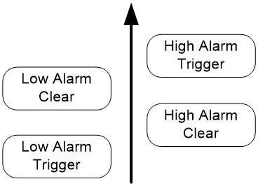
Configuration procedure
|
Step |
Command |
Remarks |
|
1. Enter system view. |
system-view |
N/A |
|
2. Enter ONU interface view. |
interface onu interface-number |
N/A |
|
3. Enable ONU alarms. |
alarm enable { onu onu-alarm | pon pon-alarm | uni uni-alarm } [ protocol { auto | ctc2.1 | ctc3.0 } ] [ threshold trigger-value clear-value ] |
By default, only the eth-port-loopback alarm is enabled for an ONU. If the protocol keyword is not specified, the autonegotiated CTC protocol is used. Whether the threshold keyword is required depends on the CTC alarms. For the support of the device for CTC alarms, see the alarm enable command in EPON Command Reference. |
Enabling packet statistics for an ONU
About ONU packet statistic collection
Perform this task to enable the packet statistics feature for an ONU.
Configuration procedure
|
Step |
Command |
Remarks |
|
1. Enter system view. |
system-view |
N/A |
|
2. Enter ONU interface view. |
interface onu interface-number |
N/A |
|
3. Enable packet statistics for the ONU. |
onu statistics enable [ period period-value ] |
By default, the packet statistics feature is enabled for an ONU, and the statistics collection interval is 4294967295 seconds. |
Enabling event reporting for an ONU
About event reporting
Perform this task for an ONU to inform the OLT of events such as configuration changes, failures, and debugging events.
Restrictions and guidelines
If an OLT manages a large number of ONUs, event report traffic from the ONUs might cause congestion. As a best practice, enable reporting only for critical events.
Configuration procedure
|
Step |
Command |
Remarks |
|
1. Enter system view. |
system-view |
N/A |
|
2. Enter ONU interface view. |
interface onu interface-number |
N/A |
|
3. Enable event reporting for the ONU. |
onu event { debug | log | trap } enable level severity |
By default, event reporting is disabled for an ONU. |
Enabling downlink traffic encryption for an ONU
About downlink traffic encryption
To protect user information against illegal access, enable encryption for the downlink traffic transmitted from the OLT to ONUs.
Configuration procedure
|
Step |
Command |
Remarks |
|
1. Enter system view. |
system-view |
N/A |
|
2. Enter ONU interface view. |
interface onu interface-number |
N/A |
|
3. Enable downlink traffic encryption for the ONU. |
encryption enable |
By default, downlink traffic encryption is enabled for an ONU. |
Updating and managing ONUs
You can update, deregister, or reboot an ONU from an OLT.
Updating ONUs
About ONU update
Table 2 shows the methods for updating ONUs. You can use one or multiple of the methods based on the network requirements.
Table 2 Remote ONU update methods
|
Method |
Description |
|
Update the ONUs of a specific type. You can perform this take multiple times to update different types of ONUs. This feature enables the OLT to automatically update ONUs that match the specified ONU type and do not have an update file. If a matching ONU comes online through a newly created ONU or RONU interface, the ONU is updated. If a matching ONU is not online, the ONU is updated when it comes online. |
|
|
Update the ONU bound to an ONU interface or RONU interface. |
|
|
Update all ONUs attached to an OLT interface. After you perform this task, whether the OLT updates a matching ONU that newly comes online depends on the creation time of the corresponding ONU interface. · If the ONU interface is created before you perform this task, the ONU will be updated. · If the ONU interface is created after you perform this task, the ONU will not be updated. |
Prerequisites for ONU update
Before you perform an update, follow these restrictions and guidelines:
· You must upload the ONU update files to the active MPU of the OLT.
· To ensure successful update for ONUs that come online after an active/standby switchover, you must upload the update files to both the active and standby MPUs.
· Make sure the update files match the ONUs to be updated. If ONUs and update files do not match, the update for the ONUs will fail. For example, if you specify the update file for ET704-A ONUs in OLT interface view, other types of ONUs attached to the OLT interface cannot be updated.
· Update commands in interface view take precedence over the update commands in FTTH view. For example, the ONU bound to ONU 3/0/1:1 is the A type. If you specify the update file 1.app for ONUs of the A type in FTTH view and specify the update file 2.app in the view of ONU 3/0/1:1, the ONU uses 2.app for update. If you cancel the update configuration in the view of ONU 3/0/1:1, the OLT does not immediately update the ONU by using 1.app. The ONU will be updated after it is reregistered and its ONU interface comes up.
Restrictions and guidelines
If you specify the start-time and duration keywords, as a best practice, perform ONU update when the endpoint users are idle, for example, in the small hours. For a single update, as a best practice, set the duration to a value between 30 minutes and 360 minutes.
As a best practice, use the H3C protocol for H3C ONUs. To update ONUs from other vendors, use the CTC protocol. When the OLT operating mode of a 10G-EPON card is changed to 128-ONU, the ONUs connected to the EPON card do not support using the H3C protocol for upgrading ONUs.
When you update ONUs by type and an ROLT interface exists on the OLT, follow these restrictions and guidelines:
· To avoid ONU update failure, do not assign a member port to or remove a member port from the ROLT interface during the update process.
· If active port switchover occurs to the ROLT interface (for example, the active port goes down) during the update process, the ONU update might fail.
During an update, follow these restrictions and guidelines:
· ONUs automatically reboot to update after they obtain update files from the OLT. To avoid update failures, do not power off the ONUs during an update.
· The update commands are automatically saved to the configuration file of the OLT after execution. If you only want to update online ONUs, use the undo form of the update commands after the update is completed on online ONUs.
· If an ONU is not online or its ONU interface is down during an update, the OLT updates the ONU after the ONU is registered and its ONU interface comes up.
Batch updating ONUs by type
|
Command |
Remarks |
|
|
1. Enter system view. |
system-view |
N/A |
|
2. Enter FTTH view. |
ftth |
N/A |
|
3. Update the ONUs of the specified type. |
update onu type onu-type [ protocol-type { h3c | ctc } ] filename filename [ start-time start-time duration minutes ] |
You can update a maximum of 64 types of ONUs at the same time in ONU interface or RONU interface view. |
Updating a single ONU
|
Step |
Command |
|
1. Enter system view. |
system-view |
|
2. Enter ONU interface view. |
interface onu interface-number |
|
3. Update the ONU. |
update onu [ protocol-type { h3c | ctc } ] filename filename [ start-time start-time duration minutes ] |
Batch updating ONUs by OLT interface
|
update onu [ protocol-type { h3c | ctc } ] filename filename [ start-time start-time duration minutes ] |
Deregistering an ONU
About ONU deregistration
After you deregister an ONU, the ONU will be re-registered.
Configuration procedure
|
Step |
Command |
|
1. Enter system view. |
system-view |
|
2. Enter ONU interface view. |
interface onu interface-number |
|
3. Deregister the ONU. |
deregister onu |
Rebooting an ONU
|
Step |
Command |
|
1. Enter system view. |
system-view |
|
2. Enter ONU interface view. |
interface onu interface-number |
|
3. Reboot the ONU. |
reboot onu |
Configuring UNIs
Configuring basic settings of UNIs
About basic UNI settings
Basic settings of a UNI include the following:
· Duplex mode—When a UNI is operating in full duplex mode, it can send and receive packets simultaneously. When a UNI is operating in half duplex mode, it can either send or receive packets at a given time. When a UNI is operating in autonegotiation mode, the UNI and its peer interface determine the duplex mode of the UNI through negotiation.
· Autonegotiation—The UNI and its peer interface determine the duplex mode, cable type, and interface rate of the UNI through negotiation.
· Flow control—If flow control is enabled for a UNI and its peer, the UNI will send messages to notify the peer to stop sending packets temporarily when congestion occurs on the UNI. This mechanism avoids packet loss.
· MDIX mode—You can use both crossover and straight-through Ethernet cables to connect UNIs to user terminals. To accommodate these types of cables, set the MDIX mode of a UNI by following these guidelines:
¡ As a best practice, set the MDIX mode to AutoMDIX. Set the MDIX mode to MDI or MDIX only when the device cannot determine the cable type.
¡ When a straight-through cable is used, configure the UNI to operate in an MDIX mode different than its peer.
¡ When a crossover cable is used, perform one of the following tasks:
- Configure the UNI to operate in the same MDIX mode as its peer.
- Configure either end to operate in AutoMDIX mode.
· Interface rate—The interface rate of a UNI can be manually set or autonegotiated by the UNI and its peer interface.
Restrictions and guidelines
On a UNI, do not enable autonegotiation and manually set the duplex mode, MDIX mode, or interface rate at the same time.
Configuration procedure
|
Step |
Command |
Remarks |
|
1. Enter system view. |
system-view |
N/A |
|
2. Enter ONU interface view. |
interface onu interface-number |
N/A |
|
3. Enable autonegotiation on a UNI. |
uni uni-number auto-negotiation |
By default, autonegotiation is enabled on a UNI. |
|
4. Configure the description for a UNI. |
uni uni-number description text |
By default, a UNI does not have a description. |
|
5. Set the duplex mode of a UNI. |
uni uni-number duplex { auto | full | half } |
By default, a UNI is operating in full-duplex mode. |
|
6. Enable flow control for a UNI. |
uni uni-number flow-control |
By default, flow control is disabled for a UNI. |
|
7. Set the MDIX mode for a UNI. |
uni uni-number mdix-mode { automdix | mdi | mdix } |
By default, the MDIX mode of a UNI is automdix. ET254 ONUs do not support this command. |
|
8. Shut down a UNI. |
uni uni-number shutdown |
By default, a UNI is up. |
|
9. Set the rate of a UNI. |
uni uni-number speed { 10 | 100 | 1000 | auto } |
By default, the rate of a UNI is 100 Mbps. |
|
10. Force a UNI to restart autonegotiation. |
uni uni-number restart auto-negotiation |
This command can be used only when autonegotiation is enabled. |
Setting the MAC learning limit on a UNI
About UNI MAC learning limit
This feature limits the MAC address table size for an ONU. A large MAC address table will degrade forwarding performance. When the MAC learning limit is reached on a UNI, the UNI stops learning MAC addresses.
Configuration procedure
|
Step |
Command |
Remarks |
|
1. Enter system view. |
system-view |
N/A |
|
2. Enter ONU interface view. |
interface onu interface-number |
N/A |
|
3. Set the MAC learning limit on a UNI. |
uni uni-number mac-address max-mac-count count |
By default, the number of MAC addresses that a UNI can learn is not limited. |
Setting the VLAN operation mode for a UNI
About the VLAN operation mode
The VLAN operation mode of a UNI can be one of the following:
· Transparent mode—Applicable when the service provider provides and manages the user-end family gateway or switch. In this scenario, the VLAN tags generated by the family gateway or switch are trusted. In transparent mode, an ONU transparently forwards the received uplink Ethernet packets (whether the Ethernet packets are VLAN-tagged or not) to the OLT without changing them. Downlink Ethernet packets are also forwarded transparently.
· Tag mode—Applicable when the VLAN tags generated by the user-end family gateway or switch are not trusted. For packet processing in tag mode, see Table 3.
· Translation mode—In translation mode, an ONU translates the CVLAN tag into a unique SVLAN tag. Translation mode ensures correct traffic forwarding if two users in an EPON system use the same VLAN ID. For packet processing in translation mode, see Table 3.
· QinQ mode—In QinQ mode, an ONU adds an SVLAN tag to packets that have a CVLAN tag. Then, the service provider can centrally manage and control the VLANs of the packets.
You can enable transparent transmission for VLANs used for special purposes when the QinQ mode is used. For example, a VLAN dedicated to a corporation or a management VLAN. When receiving packets tagged with the VLAN ID, the ONU does not add the SVLAN tag to the packets before forwarding them to the service provider network.
How an ONU in QinQ mode processes packets depends on the ONU model.
· Trunk mode—In this mode, a UNI of an ONU can send traffic from multiple VLANs. The traffic from the PVID of the UNI is untagged, and traffic from the other VLANs is VLAN-tagged. Typically, this mode is used for connecting network transmission devices. For packet processing in trunk mode, see Table 3.
· N:1 aggregation mode—In this mode, the ONU translates multiple VLAN tags of the uplink traffic into a unique SVLAN tag, and translates the SVLAN tag of the downlink traffic back into the original VLAN tags. For packet processing in N:1 aggregation mode, see Table 3.
Table 3 Packet processing for VLAN operation modes
|
VLAN operation mode |
Traffic direction |
Tagging status of packets |
Packet processing |
|
Transparent mode |
Uplink |
Tagged |
The UNI forwards the packet without any tag processing. |
|
Untagged |
|||
|
Downlink |
Tagged |
||
|
Untagged |
|||
|
Tag mode |
Uplink |
Tagged |
The UNI drops the packet. |
|
Untagged |
The UNI tags the packet with the PVID and forwards it. |
||
|
Downlink |
Tagged |
The ONU forwards the packet to the outgoing UNI based on the VLAN tag and removes the VLAN tag before sending the packet. |
|
|
Untagged |
The UNI drops the packet. |
||
|
Translation mode |
Uplink |
Tagged |
· If the VLAN tag is the PVID of the UNI, the UNI drops the packet. · If the VLAN tag matches a VLAN translation entry for the UNI, the UNI replaces the VLAN tag and forwards the packet. If no matching entry is found, the UNI drops the packet. |
|
Untagged |
The UNI tags the packet with the PVID and forwards the packet. |
||
|
Downlink |
Tagged |
· If the VLAN tag is the PVID of the UNI, the UNI removes the VLAN tag and forwards the packet. · If the VLAN tag matches a VLAN translation entry for the UNI, the UNI replaces the VLAN tag and forwards the packet. If no matching entry is found, the UNI drops the packet. |
|
|
Untagged |
The UNI drops the packet. |
||
|
Trunk mode |
Uplink |
Tagged |
If the VLAN ID of the packet is permitted by the UNI, the UNI forwards the packet. If the VLAN ID of the packet is not permitted by the UNI, the UNI drops the packet. |
|
Untagged |
The UNI tags the packet with the PVID and forwards it. |
||
|
Downlink |
Tagged |
If the VLAN ID of the packet is the PVID, processing for the packet depends on the ONU model and the software version. If the VLAN ID of the packet is permitted by the UNI, the UNI forwards the packet. If the VLAN ID of the packet is not permitted by the UNI, the UNI drops the packet. |
|
|
Untagged |
The UNI drops the packet. |
||
|
N:1 aggregation mode |
Uplink |
Tagged |
If the VLAN ID of the packet matches a VLAN aggregation entry on the UNI, the UNI translates the VLAN ID into the target VLAN ID in the entry, and records the MAC address of the packet. Then, the UNI forwards the packet. If the VLAN ID of the packet does not match a VLAN aggregation entry on the UNI, the UNI drops the packet. |
|
Untagged |
The UNI tags the packet with the PVID and forwards it. |
||
|
Downlink |
Tagged |
If the VLAN ID of the packet is the PVID, the UNI removes the VLAN tag of the packet and then forwards the packets. If the VLAN ID of the packet matches a VLAN aggregation entry on the UNI, the UNI translates the VLAN ID into the original VLAN ID in the entry based on the MAC address of the packet. Then, the UNI forwards the packet. If the VLAN ID of the packet does not match a VLAN aggregation entry on the UNI, the UNI drops the packet. |
|
|
Untagged |
The UNI drops the packet. |
Restrictions and guidelines
If the link type of all ONU interfaces on an OLT interface is access, you must set the transparent mode for UNIs of the ONUs. This setting ensures that the ONU interfaces and users receive only untagged packets.
When configuring the VLAN trunk mode, make sure the number of permitted VLANs on a UNI does not exceed 16. Otherwise, the uni vlan-mode command cannot be issued to an ONU.
Configuration procedure
|
Step |
Command |
Remarks |
|
1. Enter system view. |
system-view |
N/A |
|
2. Enter ONU interface view. |
interface onu interface-number |
N/A |
|
3. Set the VLAN operation mode for a UNI. |
· Transparent mode: · Tag mode: · Translation mode: · QinQ mode: ¡ Enable QinQ mode: ¡ (Optional.) Specify the SVLAN tag for packets with the specified CVLAN
tags: ¡ (Optional.) Enable transparent transmission for the specified CVLANs: · Trunk mode: · N:1 aggregation mode: |
By default, the VLAN operation mode of a UNI is transparent. |
Configuring UNI port isolation
About UNI port isolation
UNI port isolation improves security and allows flexible networking schemes by isolating UNIs at Layer 2. UNIs in an isolation group cannot communicate with each other.
Restrictions and guidelines
An ONU supports only one isolation group. The number of UNIs in the isolation group is not limited.
Configuration procedure
|
Step |
Command |
Remarks |
|
1. Enter system view. |
system-view |
N/A |
|
2. Enter ONU interface view. |
interface onu interface-number |
N/A |
|
3. Configure UNI port isolation. |
· Assign all UNIs on the ONU to the
isolation group: · Assign a UNI to the isolation group: |
You cannot use both commands. By default, a UNI is not in the isolation group. |
Configuring port mirroring on a UNI
About port mirroring
Port mirroring copies the packets passing through a port to another port that connects to a data monitoring device for packet analysis. The monitored port is the mirroring source port. The port connected to the data monitoring device is the mirroring destination port.
Restrictions and guidelines
A UNI cannot be both a mirroring source port and destination port.
Configuration procedure
|
Step |
Command |
Remarks |
|
1. Enter system view. |
system-view |
N/A |
|
2. Enter ONU interface view. |
interface onu interface-number |
N/A |
|
3. Configure a UNI as a mirroring source port. |
uni uni-number mirroring-port { both | inbound | outbound } |
By default, a UNI is not a mirroring source port. |
|
4. Configure a UNI as a mirroring destination port. |
uni uni-number monitor-port |
By default, a UNI is not a mirroring destination port. |
Enabling packet statistics for a UNI
About UNI packet statistic collection
Perform this task to enable the packet statistics feature for a UNI of an ONU.
Configuration procedure
|
Step |
Command |
Remarks |
|
1. Enter system view. |
system-view |
N/A |
|
2. Enter ONU interface view. |
interface onu interface-number |
N/A |
|
3. Enable packet statistics for a UNI. |
uni uni-number statistics enable [ period period-value ] |
By default, the packet statistics feature is enabled for a UNI, and the statistics collection interval is 4294967295 seconds. |
Testing the cable connected to a UNI
About the UNI cable test
Perform this task to test the cable connected to a UNI and display the test result.
Configuration procedure
|
Step |
Command |
|
1. Enter system view. |
system-view |
|
2. Enter ONU interface view. |
interface onu interface-number |
|
3. Test the cable connected to a UNI. |
uni uni-number virtual-cable-test |
Configuring ONU serial interfaces
About ONU serial interface configuration
Perform this task to set serial interface parameters and establish sessions on serial interfaces of an ONU.
Configuration procedure
|
Step |
Command |
Remarks |
|
1. Enter system view. |
system-view |
N/A |
|
2. Enter ONU interface view. |
interface onu interface-number |
N/A |
|
3. Set the number of data bits for a serial interface. |
serial interface-number databit { 5 | 6 | 7 | 8 } |
By default, the number of data bits is 8 for an ONU serial interface. |
|
4. Set the parity type for a serial interface. |
serial interface-number parity { even | mark | none | odd | space } |
By default, the parity type of an ONU serial interface is none, which indicates that no parity is used. |
|
5. Set the baud rate for a serial interface. |
serial interface-number speed { 300 | 600 | 1200 | 2400 | 4800 | 9600 | 19200 | 38400 | 57600 | 115200 } |
By default, the baud rate of an ONU serial interface is 9600 bps. |
|
6. Set the number of stop bits for a serial interface. |
serial interface-number stopbit { 1 | 1.5 | 2 } |
By default, the number of stop bits is 1 for an ONU serial interface. |
|
7. Establish a session on a serial interface. |
· Establish a TCP session with the ONU as the
client: · Establish a TCP session with the ONU as
the server: · Establish a UDP session with the ONU as
both the server and client: |
By default, no session is established on an ONU serial interface. |
Display and maintenance commands for ONUs
|
Task |
Command |
View |
|
Display IP address assignment information for an ONU that acts as a DHCP client. |
display [ ipv6 ] dhcp-client |
ONU interface view |
|
Display the MAC address entries of an ONU |
display epon mac-address interface onu interface-number [ mac mac-address ] [ vlan vlan-id ] [ pon | uni uni-number ] display epon mac-address interface onu interface-number [ count ] |
Any view |
|
Display the ONU update information. |
· In standalone mode: · In IRF mode: |
Any view |
|
Display ONU information. |
· In standalone mode: · In IRF mode: |
Any view |
|
Display information about a legal ONU by specifying its LOID. |
display onu loid loid |
Any view |
|
Display information about a legal ONU by specifying its MAC address. |
display onu mac-address mac-address |
Any view |
|
Display information about ONU neighbors. |
display onu neighbor [ interface interface-type interface-number ] |
Any view |
|
Display information about protocols supported by an ONU. |
display onu protocol { dhcp-snooping information | igmp-snooping | loopback-detection | pppoe | smart-link | stp } |
ONU interface view |
|
Display information about UNI count-based PON interface activation for an ONU. |
display onu protocol smart-link uni-bind information |
ONU interface view |
|
Display information about a serial interface on an ONU. |
display serial-information interface-number |
ONU interface view |
|
Display information about a UNI on an ONU. |
display uni uni-number |
ONU interface view |
|
Display detailed information about an ONU. |
display vendor-specific information |
ONU interface view |
|
Clear packet statistics on a serial interface on an ONU. |
reset counters serial serial-port-id |
ONU interface view |
|
Clear packet statistics on UNIs. |
reset counters uni [ uni-number ] |
ONU interface view |
|
Display information of a UNI. |
display uni uni-number |
ONU interface view |
|
Clear packet statistics on UNIs. |
reset counters uni [ uni-number ] |
ONU interface view |
ONU configuration examples
ONU binding configuration example
Network requirements
As shown in Figure 14, bind ONU1 (000f-e200-0031) and ONU2 (000f-e200-3749) to ONU interfaces ONU 3/0/1:1 and ONU 3/0/1:2, respectively.
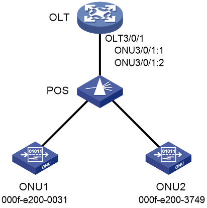
Configuration procedure
# Create ONU interfaces ONU 3/0/1:1 and ONU 3/0/1:2.
<OLT> system-view
[OLT] interface olt 3/0/1
[OLT-Olt3/0/1] using onu 1 to 2
[OLT-Olt3/0/1] quit
# Bind ONU1 to ONU 3/0/1:1.
[OLT] interface onu 3/0/1:1
[OLT-Onu3/0/1:1] bind onu-id 000f-e200-0031
[OLT-Onu3/0/1:1] quit
# Bind ONU2 to ONU 3/0/1:2.
[OLT] interface onu 3/0/1:2
[OLT-Onu3/0/1:2] bind onu-id 000f-e200-3749
[OLT-Onu3/0/1:2] quit
Verifying the configuration
# Power on ONU1 and ONU2, and verify that the ONUs have been bound to their respective ONU interface.
<OLT> display onu interface olt 3/0/1
MAC LOID LLID Dist(M) Port Mode
l/Version Sft/Epm State Aging
000f-e200-0031 1 1 Onu1/0/1:1 302
105/100 Up N/A
000f-e200-3749 2 1 Onu1/0/1:2 320
105/100 Up N/A
--- 2 entries found ---
ONU user authentication configuration example
Network requirements
As shown in Figure 15, configure the OLT to use the RADIUS server to authenticate ONU users accessing the OLT as follows:
· The shared key for exchanging packets between the OLT and the RADIUS server is expert. The usernames sent to the RADIUS server do not carry domain names.
· When a user performs authentication, both the username and the password are the MAC address of the ONU (for example, 3C8C-40CF-0523).
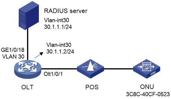
Configuration procedure
1. Configure interfaces and VLANs as shown in the network diagram. (Details not shown.)
2. Configure the OLT (RADIUS client):
# Create a RADIUS scheme named olt.
<OLT> system-view
[OLT] radius scheme olt
New RADIUS scheme.
# In RADIUS scheme olt, specify the primary authentication server with IP address 30.1.1.1 and plaintext shared key expert, and configure the device to remove the domain name from the usernames sent to the RADIUS servers.
[OLT-radius-olt] primary authentication 30.1.1.1 key simple expert
[OLT-radius-olt] user-name-format without-domain
[OLT-radius-olt] quit
# Create ISP domain 111, and configure the ISP domain to use RADIUS scheme olt for ONU user authentication.
[OLT] domain 111
[OLT-isp-111] authentication onu radius-scheme olt
[OLT-isp-111] quit
# Enable ONU authentication on OLT 1/0/1, and specify OLT 1/0/1 to use ISP domain 111 for ONU user authentication.
[OLT] interface Olt 1/0/1
[OLT-Olt1/0/1] onu authentication-domain 111
[OLT-Olt1/0/1] quit
# Enable automatic ONU binding on slot 1.
[OLT] ftth
[OLT-ftth] onu bind auto slot 1
[OLT-ftth] quit
|
|
NOTE: For information about the radius scheme, primary authentication, user-name-format, domain, and authentication onu commands, see AAA commands in Security Command Reference. |
3. Configure the RADIUS server:
# Add a local network access user named 3C8C-40CF-0523, and set the password to 3C8C-40CF-0523 in plain text for the user.
<RADIUS> system-view
[RADIUS] local-user 3C8C-40CF-0523 class network
New local user added.
[RADIUS-luser-network-3C8C-40CF-0523] password simple 3C8C-40CF-0523
[RADIUS-luser-network-3C8C-40CF-0523] quit
# Configure the IP address of the RADIUS client as 30.1.1.2 and the shared key as expert in plaintext form.
[RADIUS] radius-server client ip 30.1.1.2 key simple expert
# Activate the RADIUS server configuration.
[RADIUS] radius-server activate
|
|
NOTE: For information about the local-user, password, authorization-attribute, radius-server client, and radius-server activate commands, see AAA commands in Security Command Reference. |
Verifying the configuration
# Display information about activated RADIUS clients and RADIUS users on the RADIUS server.
[RADIUS] display radius-server active-client
Total 1 RADIUS clients.
Client IP: 30.1.1.2
[RADIUS] display radius-server active-user
Total 1 RADIUS users matched.
Username: 3C8C-40CF-0523
Description: Not configured
Authorization attributes:
VLAN ID: Not configured
ACL number: Not configured
Validity period:
Expiration time: Not configured
# Display ONU information on OLT 1/0/1.
[OLT] display onu interface olt 1/0/1
MAC LOID LLID Dist(M) Port Mode
l/Version Sft/Epm State Aging
3C8C-40CF-0523 10 1200 Onu1/0/1:1 BT/BV
S/E Up N/A
--- 1 entry found ---
The output shows that:
· After the ONU passes AAA authentication, its MAC address 3C8C-40CF-0523 is bound to ONU 1/0/1:1.
· The ONU interface is up.
ONU update configuration example
Network requirements
As shown in Figure 16, update the type-A ONU bound to ONU 3/0/1:1 at Site A with the enhanced software version 110.
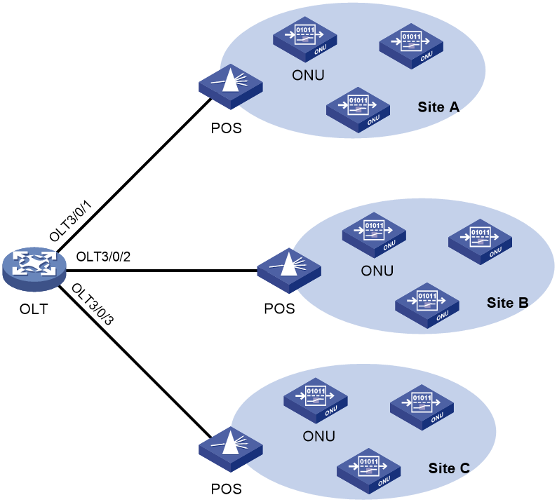
Configuration procedure
# Upload the file a110.app to the active and standby MPUs of the OLT. (Details not shown.)
# Update the type-A ONU bound to ONU 3/0/1:1 with the file a110.app.
<OLT> system-view
[OLT] interface onu 3/0/1:1
[OLT-Onu3/0/1:1] update onu filename a110.app
Update flash:/ a110.app?[Y/N]:y
Info: Download file to onu may take a long time, please wait...
Please wait while the firmware is being burnt, and check the software version after re-registration!
[OLT-Onu3/0/1:1] quit
