- Table of Contents
-
- 13-WLAN advanced features
- 01-WLAN Probe Configuration Examples
- 02-Multicast Optimization Configuration Examples
- 03-Client Rate Limiting Configuration Examples
- 04-Inter-AC Roaming Configuration Examples
- 05-Inter-AC Roaming (IPv6) Configuration Examples
- 06-Inter-AC Roaming in Local Forwarding Mode Configuration Examples
- 07-H3C Access Controllers Cooperative Roaming for 802.11v Clients Configuration Examples
- 08-WLAN Load Balancing Configuration Examples
- 09-Static Blacklist Configuration Examples
- 10-Client Quantity Control Configuration Examples
- 11-AP License Synchronization Configuration Examples
- 12-BLE Module iBeacon Transmission Configuration Examples
- 13-Medical RFID Tag Management Configuration Examples
- 14-iBeacon Management Configuration Examples
- 15-Mesh Link Establishment Between Fit APs Configuration Examples
- 16-Mesh Link Establishment Between a Fit AP and a Fat AP Configuration Examples
- 17-Auto-DFS and Auto-TPC Configuration Examples
- 18-AP Image Downloading Configuration Examples
- 19-Dual-Uplink Interfaces Configuration Guide
- 20-H3C Comware AC Cloud-Managed AP Centralized Management Configuration Examples
- Related Documents
-
| Title | Size | Download |
|---|---|---|
| 20-H3C Comware AC Cloud-Managed AP Centralized Management Configuration Examples | 126.17 KB |
|
|
|
H3C Access Controllers |
|
Cloud-Managed AP Centralized Management |
|
Configuration Examples |
|
|
Copyright © 2023 New H3C Technologies Co., Ltd. All rights reserved.
No part of this manual may be reproduced or transmitted in any form or by any means without prior written consent of New H3C Technologies Co., Ltd.
Except for the trademarks of New H3C Technologies Co., Ltd., any trademarks that may be mentioned in this document are the property of their respective owners.
The information in this document is subject to change without notice.
Contents
Example: Configuring cloud-managed APs to come online and upgrade firmware through the AC
Example: Switching cloud-managed APs to fit mode (optional)
Introduction
The following information provides an example for managing cloud-managed APs centrally. Specifically, you can use the cloud platform to control and manage APs remotely. However, when the cloud-managed APs cannot connect to the cloud platform, you can use the AC to perform centralized management (such as image downloading) on the APs to reduce O&M difficulty and management cost.
Prerequisites
The following information applies to Comware-based access controllers and WiFi-6 access points.
The configuration examples were created and verified in a lab environment, and all the devices were started with the factory default configuration. When you are working on a live network, make sure you understand the potential impact of every command on your network.
The following information is provided based on the assumption that you have basic knowledge of cloud-managed AP centralized management and auto APs.
Example: Configuring cloud-managed APs to come online and upgrade firmware through the AC
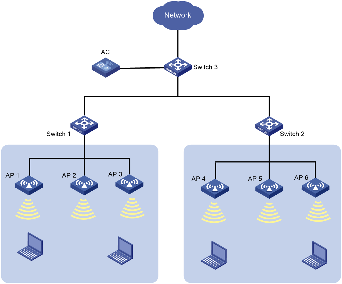
Network configuration
As shown in Figure 1, the AC is connected to Switch 3 through out-of-path deployment and Switch 3 acts as the DHCP server to assign IP addresses to APs. Switch 1 and Switch 2 supply power to APs through PoE.
Configure the feature to enable cloud-managed APs to come online and upgrade firmware through the AC. This can reduce the O&M difficulty and management cost.
Analysis
· For Switch 1 and Switch 2 to supply power to APs, enable the PoE feature on the switches.
· For Switch 3 to act as a DHCP server, enable the DHCP server feature on Switch 3.
· Enable auto AP on the AC and configure auto AP persistence.
· Download the cloud-managed AP image from the official website and save the image on the AC.
Restrictions and guidelines
· The feature is available only for Comware-based ACs of R5447P04 and later versions. Procedures and information in the examples might be slightly different depending on the software or hardware version of the access controllers and access points.
· Cloud-managed APs require licenses to come online on the AC. APs of different models use different number of license seats. To view the license seats required by APs, execute the display wlan ap-model command.
· Different cloud-managed APs support different AC models. To verify cloud-managed AP and AC compatibility, access the Home > Support > Resource Center > Software Download > Wireless page at the H3C official website and obtain the AC release notes.
About AC discovery
An AP discovers an AC and establishes a CAPWAP tunnel with the AC through the following methods:
· Static method: Discovers an AC based on the AC's IP address specified by using the wlan ac ip command on the AP.
· Dynamic methods:
¡ Through DHCP: Discovers an AC based on the AC's IP address carried in Option 43 field returned by the DHCP server.
¡ Through broadcast: Discovers an AC by broadcasting Discovery requests to 255.255.255.255.
If the AC's IP address is not specified by using the wlan ac ip command, the AP uses the DHCP and broadcast methods in sequence. If the AP uses one of the methods to establish a CAPWAP with an AC successfully, AC discovery will stop.
Procedures
Configuring Switch 1
# Enable PoE on interface GigabitEthernet 1/0/1 that connects to the cloud-managed APs.
<Switch 1> system-view
[Switch 1] interface GigabitEthernet 1/0/1
[Switch 1-GigabitEthernet1/0/1] poe enable
[Switch 1-GigabitEthernet1/0/1] quit
Configuring Switch 2
# Enable PoE on interface GigabitEthernet 1/0/1 that connects to the cloud-managed APs.
<Switch 2> system-view
[Switch 2] interface GigabitEthernet 1/0/1
[Switch 2-GigabitEthernet1/0/1] poe enable
[Switch 2-GigabitEthernet1/0/1] quit
Configuring Switch 3
# Assign IP address 192.1.0.1 to VLAN-interface 1.
<Switch 3> system-view
[Switch 3] int Vlan-interface 1
[Switch 3-Vlan-interface1] ip address 192.1.0.1 255.255.0.0
[Switch 3-Vlan-interface1] quit
# Enable DHCP services. Create DHCP address pool 1 to assign IP addresses to APs.
[Switch 3] dhcp server enable
[Switch 3] dhcp server ip-pool 1
[Switch 3-dhcp-pool-1] network 192.1.0.0 16
[Switch 3-dhcp-pool-1] gateway-list 192.1.0.1
[Switch 3-dhcp-pool-1] forbidden-ip 192.1.0.2
[Switch 3-dhcp-pool-1] quit
# Apply DHCP address pool 1 to VLAN-interface 1.
[Switch 3] interface Vlan-interface 1
[Switch 3-Vlan-interface1] dhcp server apply ip-pool 1
[Switch 3-Vlan-interface1] quit
Configuring the AC
# Assign IP address 192.1.0.2 to VLAN-interface 1 on the AC.
<AC> system-view
[AC] interface Vlan-interface1
[AC-Vlan-interface1] ip address 192.1.0.2 255.255.0.0
[AC-Vlan-interface1] quit
# Download the cloud-managed AP image to the PC. Execute the display wlan ap-model command to view the Image Name field and change the name of the image file to the same as the Image Name field.
|
|
NOTE: To download a cloud-managed AP image, access https://www.h3c.com/en/Support/Resource_Center/Software_Download/Wireless/. |
For example, change the file name from WA6500A-CMW710-E2588P01.ipe to wa6500a.ipe.
# Configure the PC as the FTP server. Connect the AC to the PC and then download the cloud-managed AP image through FTP.
<AC> ftp 192.1.0.5
ftp> get wa6500a.ipe
ftp> quit
# Enable AP firmware upgrade. Specify the mapping relations between AP model and software version number.
|
|
NOTE: · After AP firmware upgrade is enabled, the AC compares the current AP version with the specified version in the binding. If the versions are the same, the AC will not perform the upgrade. If the versions are different, the AC will start the upgrade. · When specifying the mapping relations between AP model and software version number, you must save the AP image for upgrade to directory apimg on the AC and make sure the version number is the same as configured. |
<AC> system-view
[AC] wlan ap-group default-group
[AC-wlan-ap-gro-default-group] firmware-upgrade enable
[AC-wlan-ap-group-default-group] quit
# Configure the AC to obtain the AP image in the local folder with the top priority.
[AC] wlan image-load filepath local
# Specify the mapping relation between the AP model and the AP version number.
[AC] wlan apdb oasisap WA6526H Ver.A E2588P01
# Enable auto AP.
[AC] wlan auto-ap enable
# Enable auto AP association to the AC.
[AC] wlan auto-ap fat-and-cloud enable
# Convert online auto APs to manual APs.
[AC] wlan auto-ap persistent all
# Enable the system to automatically convert auto APs to manual APs. This configuration takes effect only on APs that come online afterward.
[AC] wlan auto-persistent enable
Verifying the configuration
# Use the display wlan ap all command to view the AP information. Verify that the default AP name is the device MAC address, the AP state is IL during image loading and is R/M after the AP comes online.
[AC] display wlan ap all
Total number of APs: 1
Total number of connected APs: 1
Total number of connected manual APs: 0
Total number of connected auto APs: 1
Total number of connected common APs: 1
Total number of connected WTUs: 0
Total number of inside APs: 0
Maximum supported APs: 3072
Remaining APs: 3071
Total AP licenses: 128
Local AP licenses: 128
Server AP licenses: 0
Remaining AP licenses: 127
Sync AP licenses: 0
AP information
State : I = Idle, J = Join, JA = JoinAck, IL = ImageLoad
C = Config, DC = DataCheck, R = Run, M = Master, B = Backup
AP name AP ID State Model Serial ID
741f-4a35-6e00 1 IL WA6526H 219801A28N819CE0002T
# Use the display wlan ap name 741f-4a35-6e00 verbose command to verify that the S/W version field is E2588P01 after the AP firmware upgrade.
[AC] display wlan ap name 741f-4a35-6e00 verbose
AP name : 741f-4a35-6e00
AP ID : 1
AP group name : default-group
State : Run
Backup type : Master
Ready-for-Switchover : Ready
Online time : 1 days 22 hours 29 minutes 40 seconds
System uptime : N/A
Model : WA6526H
Region code : CN
Region code lock : Disabled
Serial ID : 219801A28N819CE0002T
MAC address : 741f-4a35-6e00
IP address : 192.1.0.5
UDP control port number : 27392
UDP data port number : 27392
H/W version : Ver.A
S/W version : E2588P01
Configuration files
· Switch 1
#
interface GigabitEthernet 1/0/1
poe enable
#
· Switch 2
#
interface GigabitEthernet 1/0/1
poe enable
#
· Switch 3
#
dhcp server ip-pool 1
gateway-list 192.1.0.1
network 192.1.0.0 mask 255.255.0.0
forbidden-ip 192.1.0.2
#
interface Vlan-interface1
ip address 192.1.0.1 255.255.0.0
dhcp server apply ip-pool 1
#
· AC
#
interface Vlan-interface1
ip address 192.1.0.2 255.255.0.0
#
wlan ap-group default-group
firmware-upgrade enable
#
wlan image-load filepath local
#
wlan apdb oasisap WA6526H Ver.A E2588P01
#
wlan auto-ap enable
wlan auto-ap fat-and-cloud enable
wlan auto-ap persistent all
wlan auto-persistent enable
#
Example: Switching cloud-managed APs to fit mode (optional)
Restrictions and guidelines
If an AP is already in fit mode, configuring the feature has no effect on the AP.
Network configuration
To connect cloud-managed APs to an AC to achieve centralized management, you can switch the AP mode from cloud to fit. After the switching, the APs operate as fit APs.
Procedures
# Enter the view of default AP group default-group.
<AC> system-view
[AC] wlan ap-group default-group
# Configure cloud-managed APs to act in fit mode.
[AC-wlan-ap-group-default-group] ap-mode fit
[AC-wlan-ap-group-default-group] quit
Verifying the configuration
# Use the display wlan ap name 741f-4a35-6e00 verbose command to verify that the AP type filed is Normal AP.
[AC]dis wlan ap name 741f-4a35-6e00 verbose
AP name : 741f-4a35-6e00
AP ID : 1
AP group name : default-group
State : Idle
Backup type : Idle
Ready-for-Switchover : Not ready
Online time : N/A
System uptime : N/A
Model : WA6526H
Region code : CN
Region code lock : Disabled
Serial ID : 219801A28N819CE0002T
MAC address : Not configured
IP address : N/A
UDP control port number : N/A
UDP data port number : N/A
H/W version : N/A
S/W version : N/A
Boot version : N/A
USB state : N/A
Power level : N/A
Power info : N/A
Description : Not configured
Priority : 4
Echo interval : 10 seconds
Echo count : 3 counts
Keepalive interval : 10 seconds
Discovery-response wait-time : 2 seconds
Statistics report interval : 50 seconds
Fragment size (data) : 1500
Fragment size (control) : 1450
MAC type : N/A
Tunnel mode : N/A
CAPWAP data-tunnel status : Down
Discovery type : N/A
Retransmission count : 3
Retransmission interval : 5 seconds
Firmware upgrade : Enabled
Sent control packets : 0
Received control packets : 0
Echo requests : 0
Lost echo responses : 0
Average echo delay : 0
Last reboot reason : N/A
Latest IP address : N/A
Current AC IP : N/A
Tunnel down reason : N/A
Connection count : 0
Backup IPv4 : Not configured
Backup IPv6 : Not configured
Ctrl-tunnel encryption : Disabled
Ctrl-tunnel encryption state : Not encrypted
Data-tunnel encryption : Disabled
Data-tunnel encryption state : Not encrypted
LED mode : Normal
Remote configuration : Disabled
EnergySaving Level : N/A
AP type : Normal AP
Configuration files
· AC
#
wlan ap-group default-group
ap-mode fit
#
Related documentation
· AP Management Command Reference in H3C Access Controllers Command References
· AP Management Configuration Guide in H3C Access Controllers Configuration Guides
