- Table of Contents
-
- 03-Layer 2 Configuration Guide
- 00-Preface
- 01-Ethernet Interface Configuration
- 02-Loopback and Null Interface Configuration
- 03-MAC Address Table Configuration
- 04-Spanning Tree Configuration
- 05-Loopback Detection Configuration
- 06-VLAN Configuration
- 07-Layer 2 Forwarding Configuration
- 08-PPP Configuration
- 09-Ethernet Link Aggregation Configuration
- 10-DCC Configuration
- Related Documents
-
| Title | Size | Download |
|---|---|---|
| 05-Loopback Detection Configuration | 112.34 KB |
Configuring loopback detection
Loopback detection configuration task list
Configuring the loopback detection interval
Displaying and maintaining loopback detection
Overview
The loopback detection mechanism promptly notifies you when loops occur, so that you can check network connections and configurations and remove the loops by automatically shutting down the looped ports. The loopback detection mechanism notifies you of the network loop by printing logs and sending trap messages, and may shut down the looped port as configured.
For more information about logs and trap messages, see Network Management and Monitoring Configuration Guide.
Basic concepts
Loopback detection frame
A device detects loops by sending loopback detection frames and then checking whether these frames return to a port on the device (not necessarily to the sending ports). If the loopback detection frame is returned, the port is considered looped.
Figure 1 Ethernet header of a loopback detection frame
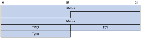
Figure 1 shows the format of the Ethernet header of a loopback detection frame. The Ethernet header contains the following fields:
· DMAC—Destination MAC address of the loopback detection frame, which is the multicast MAC address 010F-E200-0007. When a loopback detection-enabled device receives a frame with this destination MAC address, it sends the frame to the CPU and broadcasts the frame in the VLAN from which the frame was originally received.
· SMAC—Source MAC address of the loopback detection frame, which is the bridge MAC address of the sending device.
· TPID—Type of the VLAN tag, with the value of 0x8100.
· TCI—Information about the VLAN tag, including priority and VLAN ID.
· Type—Protocol type, with the value of 0x8918.
Figure 2 Inner header of a loopback detection frame
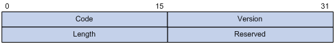
Figure 2 shows the format of the inner header of a loopback detection frame. The inner header contains the following fields:
· Code—Protocol sub-type, with the value of 0x0001, indicating the loopback detection protocol.
· Version—Protocol version, with the value of 0x0000, which is reserved.
· Length—Length of the loopback detection frame, including the inner header, but not the Ethernet header.
· Reserved—This field is reserved.
Loopback detection frames are constructed in the form of TLV (type/length/value) triplets. Table 1 lists the TLVs (required or optional) supported by the loopback detection mechanism.
Table 1 TLVs supported by the loopback detection mechanism
|
TLV |
Description |
Remarks |
|
End of PDU |
End of a PDU. |
Optional. |
|
Device ID |
Bridge MAC address of the sending device. |
Required. |
|
Port ID |
ID of the PDU sending port. |
Optional. |
|
Port Name |
Name of the PDU sending port. |
Optional. |
|
System Name |
Device name. |
Optional. |
|
Chassis ID |
Chassis ID of the sending port. |
Optional. |
|
Slot ID |
Slot ID of the sending port. |
Optional. |
|
Sub Slot ID |
Sub-slot ID of the sending port. |
Optional. |
Loopback detection interval
Loopback detection configuration task list
|
Task |
Remarks |
|
Required |
|
|
Optional |
Enabling loopback detection
|
Step |
Command |
Remarks |
|
1. Enter system view. |
system-view |
N/A |
|
2. Enable loopback detection. |
loopback-detection enable |
Disabled by default. |
Configuring the loopback detection interval
With loopback detection enabled, the system sends loopback detection frames at a specified interval. The shorter this interval is, the faster the system can detect loops, but the more system resources will be used. You must consider both system performance and loop detection speed when choosing an appropriate interval.
To configure the loopback detection interval:
|
Step |
Command |
Remarks |
|
1. Enter system view. |
system-view |
N/A |
|
2. Configure the loopback detection interval. |
loopback-detection interval-time interval |
30 seconds by default. |
Displaying and maintaining loopback detection
|
Task |
Command |
Remarks |
|
Display the status of loopback detection. |
display loopback-detection [ | { begin | exclude | include } regular-expression ] |
Available in any view. |
Loopback detection configuration example
Network requirements
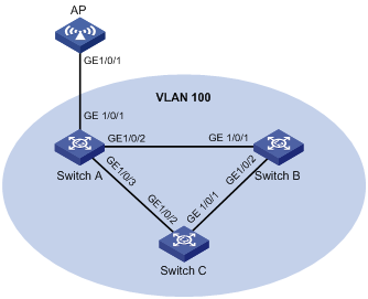
As shown in Figure 3:
· Switch A, Switch B, and Switch C form a ring-shaped network. The AP accesses the network through Switch A. The network administrator typically shuts down GigabitEthernet 1/0/1 of Switch B to prevent loops in the network.
· Configure loopback detection on AP so that when a loop resulting from incorrect configuration occurs, AP can remind the user to check the network connections by printing log information and sending trap messages.
Figure 3 Network diagram for loopback detection
Configuration procedure
Configuring the AP
# Enable loopback detection globally and set the loopback detection interval to 35 seconds.
<AP> system-view
[AP] loopback-detection enable
[AP] loopback-detection interval-time 35
# Configure GigabitEthernet 1/0/1 as trunk ports and assign them to VLAN 100. Enable loopback detection on GigabitEthernet 1/0/1 to discard packets upon the interface detects loops.
<AP> system-view
[AP] interface GigabitEthernet 1/0/1
[AP] vlan 100
[AP-vlan100] quit
[AP] interface GigabitEthernet1/0/1
[AP-GigabitEthernet1/0/1] port link-type trunk
[AP-GigabitEthernet1/0/1] port trunk permit vlan 100
[AP-GigabitEthernet1/0/1] loopback-detection enable
[AP-GigabitEthernet1/0/1] loopback-detection control enable
[AP-GigabitEthernet1/0/1] quit
Configuring Switch A
# Create VLAN 100.
<SwitchA> system-view
[SwitchA] vlan 100
[SwitchA–vlan100] quit
# Configure GigabitEthernet 1/0/2 and GigabitEthernet 1/0/3 as trunk ports and assign them to VLAN 100.
[SwitchA] interface GigabitEthernet 1/0/2
[SwitchA-GigabitEthernet1/0/2] port link-type trunk
[SwitchA-GigabitEthernet1/0/2] port trunk permit vlan 100
[SwitchA-GigabitEthernet1/0/2] quit
[SwitchA] interface GigabitEthernet 1/0/3
[SwitchA-GigabitEthernet1/0/3] port link-type trunk
[SwitchA-GigabitEthernet1/0/3] port trunk permit vlan 100
[SwitchA-GigabitEthernet1/0/3] quit
Configuring Switch B
# Create VLAN 100.
<SwitchB> system-view
[SwitchB] vlan 100
[SwitchB–vlan100] quit
# Configure GigabitEthernet 1/0/1 and GigabitEthernet 1/0/2 as trunk ports and assign them to VLAN 100.
[SwitchB] interface GigabitEthernet 1/0/1
[SwitchB-GigabitEthernet1/0/1] port link-type trunk
[SwitchB-GigabitEthernet1/0/1] port trunk permit vlan 100
[SwitchB-GigabitEthernet1/0/1] quit
[SwitchB] interface GigabitEthernet 1/0/2
[SwitchB-GigabitEthernet1/0/2] port link-type trunk
[SwitchB-GigabitEthernet1/0/2] port trunk permit vlan 100
[SwitchB-GigabitEthernet1/0/2] quit
Configuring Switch C
# Create VLAN 100.
<SwitchC> system-view
[SwitchC] vlan 100
[SwitchC–vlan100] quit
# Configure GigabitEthernet 1/0/1 and GigabitEthernet 1/0/2 as trunk ports and assign them to VLAN 100.
[SwitchC] interface GigabitEthernet 1/0/1
[SwitchC-GigabitEthernet1/0/1] port link-type trunk
[SwitchC-GigabitEthernet1/0/1] port trunk permit vlan 100
[SwitchC-GigabitEthernet1/0/1] quit
[SwitchC] interface GigabitEthernet 1/0/2
[SwitchC-GigabitEthernet1/0/2] port link-type trunk
[SwitchC-GigabitEthernet1/0/2] port trunk permit vlan 100
[SwitchC-GigabitEthernet1/0/2] quit
Verifying the configuration
After the configurations are completed, use the display loopback-detection command to check the status of loopback detection on each device.
# Display the loopback detection status on the AP.
[AP] display loopback-detection
Loopback-detection is running.
Detection interval is 35 seconds.
No loopback is detected on any interface.
The output shows that loopback detection is enabled on the AP, and no looped ports are detected.
# Display the loopback detection status on Switch A.
[SwitchA] display loopback-detection
Loopback-detection is not running.
# Display the loopback detection status on Switch B.
[SwitchB] display loopback-detection
Loopback-detection is not running.
# Display the loopback detection status on Switch C.
[SwitchC] display loopback-detection
Loopback-detection is not running.
The output shows that loopback detection is not enabled on Switch A, Switch B, and Switch C.
Assume that later on, GigabitEthernet 1/0/1 of Switch B is brought up by the network administrator by mistake. Within a loopback detection interval, the AP will detect a loop on its port GigabitEthernet 1/0/1. Consequently, it automatically shuts down the port and prints the following log information:
%Jan 27 12:07:29:624 2009 WA4620i-ACN DRVMSG/1/DRVMSG: GigabitEthernet1/0/1:
Network loopback does exist on port, please check it
%Jan 27 12:07:29:624 2009 WA4620i-ACN DRVMSG/1/DRVMSG: GigabitEthernet1/0/1:
Network loopback does exist on port, please check it
When you see the log information, use the display loopback-detection command again to display the loopback detection status on the AP.
# Display the loopback detection operating status on the AP.
[AP] display loopback-detection
Loopback-detection is running.
Detection interval is 35 seconds.
Following port(s) has(have) loopback link:
GigabitEthernet1/0/1
The output shows that a loop is detected on GigabitEthernet 1/0/1.
