- Table of Contents
-
- 02-WLAN Configuration Guide
- 00-Preface
- 01-WLAN Interface Configuration
- 02-WLAN Access Configuration
- 03-WLAN Security Configuration
- 04-IACTP Tunnel and WLAN Roaming Configuration
- 05-WLAN RRM Configuration
- 06-WLAN IDS Configuration
- 07-WLAN QoS Configuration
- 08-WLAN Mesh Link Configuration
- 09-Advanced WLAN Configuration
- 10-WLAN High Availability Configuration
- 11-WLAN IPS Configuration
- 12-WLAN Optimization Configuration
- Related Documents
-
| Title | Size | Download |
|---|---|---|
| 09-Advanced WLAN Configuration | 708.15 KB |
Displaying and maintaining WLAN sniffer
Radio-based WLAN sniffer configuration example
Client-based WLAN sniffer configuration example
Configuring basic network settings for an AP
Configuring an AP to support the 802.1X client function
AP provision configuration example
Configuring a VLAN pool on a radio
Displaying and maintaining VLAN pool
VLAN pool configuration example
Configuring static wireless location
Configuring dynamic wireless location
Displaying and maintaining wireless location
Wireless location configuration example
Dynamic wireless location configuration example
Static wireless location configuration example
Configuring multicast optimization
Configuring multicast optimization
Displaying and maintaining multicast optimization
Multicast optimization configuration example
Configuring the operating mode for an AP
Enabling spectrum analysis to trigger channel adjustment
Displaying and maintaining spectrum analysis
Spectrum analysis configuration example
Hotspot-based BAS AC assignment configuration example
Configuring a guest access tunnel
Configuring a guest access tunnel
Configuration restrictions and guidelines
Displaying and maintaining guest access tunnels
Guest access tunnel configuration example
Bonjour service advertisement snooping
Bonjour query snooping and response
Setting the threshold for starting sending multicast responses
Enabling active query for Bonjour services
Displaying and maintaining Bonjour gateway
Bonjour gateway configuration example
Configuring a Hotspot 2.0 policy
Configuring automatic network discovery
Configuring network management parameters
Configuring WLAN sniffer
Support for this feature depends on the device model. For more information, see About the H3C Access Controllers Configuration Guides.
Wireless tracing is limited and is intended for support only and assisting additional troubleshooting tool only.
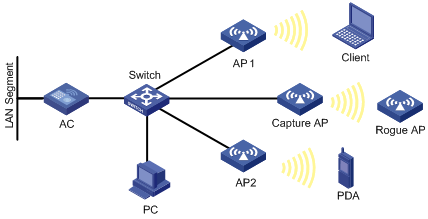
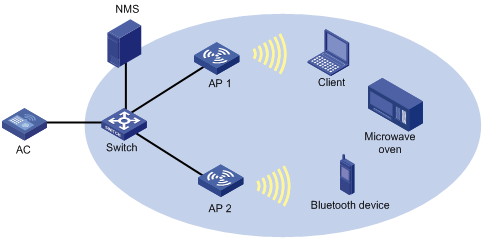
In a wireless network, it is difficult to locate signal interference and packet collision by debugging information or terminal display information of WLAN devices. WLAN sniffer facilitates the troubleshooting by using an AP as a packet sniffer to listen to, capture, and record wireless packets. The information about captured packets is stored in a CAP file.
As shown in Figure 1, enable WLAN sniffer on the Capture AP. The Capture AP listens to wireless packets in the network and stores captured packets in the specified CAP file. The administrator can download the CAP file to a PC for analysis.
The AP supports the following WLAN sniffer methods:
· Radio-based—If you enable WLAN sniffer on a radio of the AP, the radio can capture control, management, and data packets that it can monitor on its working channel.
· Client-based—You can use this method to capture management, control, and data packets sent or received by specified clients. The packets contain client connection or status update information.
Configuring WLAN sniffer
Follow these guidelines when you configure WLAN sniffer:
· An auto AP does not support the WLAN sniffer function.
· To enable WLAN sniffer on a radio, the AP must be in Run state, and the working channel of the radio must be manually specified.
· Disabling the sniffer-enabled radio, deleting the Capture AP, disconnecting the Capture AP from the AC, or disabling WLAN sniffer stops the sniffer operation. The captured packets are saved to the specified CAP file in the default storage medium. The default storage medium varies by device model.
· The working mode of the AP cannot be changed with the work-mode monitor or device-detection enable command when it is capturing packets.
· When you configure client-based WLAN sniffer, you need to create an Ethernet frame header ACL and configure the permit statement in the ACL rule to match the MAC addresses of clients you want to capture. Only source MAC addresses can be matched. For more information about ACL configuration, see ACL and QoS Configuration Guide.
To configure WLAN sniffer:
|
Step |
Command |
Remarks |
|
1. Enter system view. |
system-view |
N/A |
|
2. Set the maximum number of packets that can be captured by an AP. |
wlan capture packet-limit packet-limit |
Optional. By default the maximum number of packets that can be captured by an AP is 10000. · You are not allowed to change the maximum number of packets that can be captured by an AP during the WLAN sniffer process. · WLAN sniffer stops when the maximum number is reached. |
|
3. Set the name of the CAP file to which the captured packets are saved. |
wlan capture file-name file-name |
Optional. The default name is CaptureRecord. · The file has a fixed extension .dmp, which is not configurable. · You are not allowed to change the name of the CAP file during the WLAN sniffer process. |
|
4. Enable WLAN sniffer on a radio of an AP. |
· Enable radio-based
WLAN sniffer: · Enable client-based
WLAN sniffer: |
Required. Use either method. WLAN sniffer can be enabled for only one radio of an AP. The radio must have been enabled and its working channel has been manually specified. The AP that holds the radio must have been associated with the AC. |
|
5. Disable WLAN sniffer. |
wlan capture stop |
Optional. |
Displaying and maintaining WLAN sniffer
|
Task |
Command |
Remarks |
|
Display information about WLAN sniffer enabled APs. |
display wlan capture [ | { begin | exclude | include } regular-expression ] |
Available in any view. |
Radio-based WLAN sniffer configuration example
Network requirements
As shown in Figure 2, on the AC, enable WLAN sniffer for an AP to capture wireless packets.

Configuration procedure
To enable WLAN sniffer on a radio, the AP must operate in normal mode and must be in Run state, and the working channel of the radio must be manually specified. The working channel for WLAN sniffer in this example is 11. For information about how to configure the operating mode for an AP, see "Configuring WLAN access."
1. Configure WLAN services on the AC. For more information, see "Configuring WLAN access."
2. Enable radio-based WLAN sniffer on Radio 2 of the AP named captureap.
<AC> system-view
[AC] wlan capture start ap captureap radio 2
Verifying the configuration
# Display information about the AP that is capturing packets. The output shows that Radio 2 on the AP is capturing packets.
[AC] display wlan capture
WLAN Capture
--------------------------------------------------------------------------------
AP Name : captureap
Radio : 2
Radio Mode : 802.11g
Channel : 11
Capture Limit : 10000
File Name : CaptureRecord.dmp
Status : Capturing
--------------------------------------------------------------------------------
Client-based WLAN sniffer configuration example
Network requirements
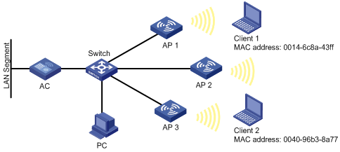
As shown in Figure 3, enable client-based WLAN sniffer to capture wireless packets of Client 1 and Client 2.
Configuration procedure
1. Configure WLAN services on the AC. For more information, see "Configuring WLAN access."
2. Configure the client-based WLAN sniffer function:
<AC> system-view
[AC] acl number 4400
[AC-acl-ethernetframe-4400] rule permit source-mac 0014-6c8a-43ff FFFF-FFFF-FFFF
[AC-acl-ethernetframe-4400] rule permit source-mac 0040-96b3-8a77 FFFF-FFFF-FFFF
[AC-acl-ethernetframe-4400] quit
[AC] wlan capture start client acl 4400
3. Verify the configuration:
# Display information about the client-based WLAN sniffer function.
[AC] display wlan capture
WLAN Capture
--------------------------------------------------------------------------------
Capture Type : Client
ACL : 4400
Capture Limit : 10000
File Name : CaptureRecord.dmp
Status : Capturing
--------------------------------------------------------------------------------
Configuring AP provision
AP provision allows you to configure network settings for fit APs on an AC. The AC automatically assigns these settings to the fit APs in run state over AC-AP connections. This feature avoids configuring APs one by one from a terminal, greatly reducing the work load in large WLAN networks.
Configuring basic network settings for an AP
If you change the network settings for an associated AP, you need to save the settings to the wlan_ap_cfg.wcfg file of the AP, and restart the AP to validate the new settings.
To configure AP network settings:
|
Step |
Command |
Remarks |
|
1. Enter system view. |
system-view |
N/A |
|
2. Set a global AC so that APs can discover the AC. |
wlan ap-provision ac { host-name host-name | ip ip-address | ipv6 ipv6-address } |
Optional. By default, no global AC is specified. |
|
3. Set a global DNS server. |
wlan ap-provision dns server { ip ip-address | ipv6 ipv6-address } |
Optional. By default, no global DNS server is specified. |
|
4. Set a global domain name. |
wlan ap-provision dns domain domain-name |
Optional. By default, no global domain name is specified. |
|
5. Enter AP template view. |
wlan ap ap-name [ model model-name [ id ap-id ] ] |
Specify the AP model only when you create an AP template. |
|
6. Create and enter AP provision view. |
provision |
After you create AP provision view, the device automatically adds the vlan untagged 1 command for the AP. This command also enables the AP provision function. An auto AP cannot be configured with the AP provision function. |
|
7. Configure the initial country code for the AP when it scans the mesh network at first startup. |
initial-country-code code |
Optional. By default, no initial country code is configured for an AP when it scans the mesh network at first startup. |
|
8. Set an AC so that the AP can discover the AC. |
ac { host-name host-name | ip ip-address | ipv6 ipv6-address } |
Optional. By default, no AC is specified for the AP. The IPv6 address of an AC cannot be the link local address. The wlan ap-provision ac command applies to all APs, and the ac command in AP provision view applies to the current AP. If you configure both commands, the configuration in AP provision view applies to the current AP. |
|
9. Set a DNS server for the AP. |
dns server { ip ip-address | ipv6 ipv6-address } |
Optional. By default, no DNS server is specified for the AP. The wlan ap-provision dns server command applies to all APs, and the dns server command in AP provision view applies to the current AP. If you configure both commands, the configuration in AP provision view applies to the current AP. |
|
10. Set a domain name suffix for the DNS server. |
dns domain domain-name |
Optional. By default, no domain name is specified for the DNS server. The wlan ap-provision dns domain command applies to all APs, and the dns domain command in AP provision view applies to the current AP. If you configure both commands, the configuration in AP provision view applies to the current AP. |
|
11. Set the default VLAN ID for the Ethernet interface on the AP. |
vlan pvid vlan-id |
Optional. By default, the default VLAN ID of the Ethernet interface on the AP is 1. |
|
12. Set a list of VLANs whose packets are sent tagged on the Ethernet interface of the AP. |
vlan tagged vlan-id-list |
Optional. By default, no VLANs are configured. |
|
13. Set a list of VLANs whose packets are sent untagged on the Ethernet interface of the AP. |
vlan untagged vlan-id-list |
Optional. By default, the packets of VLAN 1 are sent untagged on the Ethernet interface of the specified AP. |
|
14. Set an IP address for the management VLAN interface of the AP. |
ip address ip-address { mask | mask-length } |
Optional. By default, no IP address is specified. |
|
15. Set an IPv6 address for the management VLAN interface of the AP. |
ipv6 address { ipv6-address prefix-length | ipv6-address/prefix-length } |
Optional. By default, no IPv6 address is specified. The management of the AP is VLAN 1. |
|
16. Set the gateway of the AP. |
gateway { ip ip- address | ipv6 ipv6-address } |
Optional. By default, no gateway is configured for the AP. |
|
17. Configure the AP to use IPsec to encrypt the control tunnel. |
tunnel encryption ipsec pre-shared-key { cipher | simple } key |
By default, the AP does not encrypt the control tunnel. This command is used to configure AC-AP tunnel encryption with IPsec. For more information about AC-AP tunnel encryption with IPsec, see "Configuring WLAN access." |
|
18. Configure the AP to use IPsec to encrypt the data tunnel. |
data-tunnel encryption enable |
Optional. By default, the AP does not encrypt the data tunnel. This command is used to configure AC-AP tunnel encryption with IPsec. For more information about AC-AP tunnel encryption with IPsec, see "Configuring WLAN access." |
|
19. Save the configurations in AP provision view to the wlan_ap_cfg.wcfg file of the specified AP or all APs. |
save wlan ap provision { all | name ap-name } |
This command only applies to APs in the Run state. For more information about the command, see WLAN Command Reference. |
|
20. Return to AP template view. |
quit |
N/A |
|
21. Enable auto recovery of startup with zero-configuration. |
provision auto-recovery enable |
Optional. By default, auto recovery of startup with zero-configuration is enabled. |
|
22. Remove the wlan_ap_cfg.wcfg file of the specified AP or all APs. |
reset wlan ap provision { all | name ap-name } |
Optional. This command only applies to APs in the Run state. |
You can execute the save wlan ap provision and reset wlan ap provision commands in any view.
Configuring an AP to support the 802.1X client function
To prevent rogue AP attacks, you can enable 802.1X authentication on the access device connected to an AP. To implement this function, the AP must support the 802.1X client function.
To enable an AP to be authenticated as an 802.1X client, perform the following tasks:
1. Make sure the AC and AP have established a tunnel with each other.
2. Apply the 802.1X authentication configuration to the wlan_ap_cfg.wcfg file of the AP through the AP provision function.
3. Enable 802.1X authentication on the access device.
4. Reboot the AP.
To configure an AP to support the 802.1X client function:
|
Step |
Command |
Remarks |
|
1. Enter system view. |
system-view |
N/A |
|
2. Specify the AP name and enter AP template view. |
wlan ap ap-name [ model model-name [ id ap-id ] ] |
You must specify the model name when you create an AP template. |
|
3. Enter AP configuration view. |
provision |
After you create AP provision view, the device automatically adds the vlan untagged 1 command for the AP. This command also enables the AP provision function. An auto AP cannot be configured with the AP provision function. |
|
4. Set an authentication username for the AP. |
dot1x supplicant username username |
By default, no authentication username is configured for an AP when it acts as an 802.1X client. |
|
5. Set an authentication password for the AP. |
dot1x supplicant password { simple | cipher } |
By default, no authentication password is configured for an AP when it acts as an 802.1X client. |
|
6. Set the authentication method for the AP. |
dot1x supplicant eap-method { md5 | peap-gtc | peap-mschapv2 | ttls-gtc | ttls-mschapv2 } |
Optional. By default, no authentication method is configured for an AP when it acts as an 802.1X client. The MD5 authentication method is used by default after you enable the 802.1X client function for the AP. |
|
7. Enable the 802.1X client function for the AP. |
dot1x supplicant enable |
By default, the 802.1X client function is not enabled for an AP. |
AP provision configuration example
Network requirements
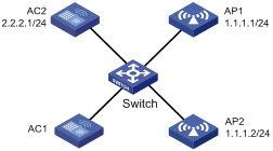
Configure AP provision on AC 1 to assign the following network settings to the fit APs over AC-AP connections:
· IP address 1.1.1.1/24 of AP 1 and IP address 1.1.1.2/24 of AP 2.
· IP address 2.2.2.1/24 of AC 2 so that the APs can discover AC 2.
· Username test and password test for AP 1 and AP 2 when they operate as 802.1X clients.
· Authentication method peap-mschapv2.
· 802.1X client function enabled on Ethernet interfaces on both AP 1 and AP 2.
Figure 4 Network diagram
Configuration procedure
Make sure AP 1 and AP 2 have established connections to AC 1 and AC 2 can reach 1.1.1.0/24 at Layer 3. Otherwise, the AC cannot assign the network settings to them.
1. Enable the 802.1X function on the switch. For more information, see the configuration guide for the switch.
2. Configure AC 1:
# Specify the IP address of AC 2 so that AP 1 and AP 2 can discover AC 2.
<AC1> system-view
[AC1] wlan ap-provision ac ip 2.2.2.1
# Enter AP 1 provision view. Set the IP address of the management VLAN interface of AP 1 to 1.1.1.1.
[AC1] wlan ap ap1 model WA3628i-AGN
[AC1-wlan-ap-ap1] provision
[AC1-wlan-ap-ap1-prvs] ip address 1.1.1.1 24
# Configure AP 1 to use username test and password test when it acts as an 802.1X client, and set the authentication method to peap-mschapv2.
[AC1-wlan-ap-ap1-prvs] dot1x supplicant username test
[AC1-wlan-ap-ap1-prvs] dot1x supplicant password simple test
[AC1-wlan-ap-ap1-prvs] dot1x supplicant eap-method peap-mschapv2
# Enable the 802.1X client function on the Ethernet interface on AP 1.
[AC1-wlan-ap-ap1-prvs] dot1x supplicant enable
[AC1-wlan-ap-ap1-prvs] quit
[AC1-wlan-ap-ap1] quit
# Enter AP 2 provision view, and set the IP address of the management VLAN interface of AP 2 to 1.1.1.2.
[AC1] wlan ap ap2 model WA3628i-AGN
[AC1-wlan-ap-ap2] provision
[AC1-wlan-ap-ap2-prvs] ip address 1.1.1.2 24
# Configure AP 2 to use username test and password test when it acts as an 802.1X client, and set the authentication method to peap-mschapv2.
[AC1-wlan-ap-ap2-prvs] dot1x supplicant username test
[AC1-wlan-ap-ap2-prvs] dot1x supplicant password simple test
[AC1-wlan-ap-ap2-prvs] dot1x supplicant eap-method peap-mschapv2
# Enable the 802.1X client function on the Ethernet interface on AP 2.
[AC1-wlan-ap-ap2-prvs] dot1x supplicant enable
# Save the configurations in AP provision view to the wlan_ap_cfg.wcfg files of the APs.
[AC1-wlan-ap-ap2-prvs] save wlan ap provision all
# Reboot AP 1 and AP 2 to validate the configuration.
<AC1> reset wlan ap name ap1
<AC1> reset wlan ap name ap2
3. Configure AC 2:
# Create a WLAN ESS interface.
<AC2> system-view
[AC2] interface wlan-ess 1
[AC2-WLAN-ESS1] quit
# Create a clear-type WLAN service template, set the SSID of the service template to service and bind the WLAN-ESS interface to this service template.
[AC2] wlan service-template 1 clear
[AC2-wlan-st-1] ssid service
[AC2-wlan-st-1] bind wlan-ess 1
[AC2-wlan-st-1] authentication-method open-system
[AC2-wlan-st-1] service-template enable
[AC2-wlan-st-1] quit
# Create an AP template named ap1, and specify its model and serial ID.
[AC2] wlan ap ap1 model WA3628i-AGN
[AC2-wlan-ap-ap1] serial-id 210235A29G007C000020
[AC2-wlan-ap-ap1] description L3office
# Set the radio type to 802.11gn, and channel to 11.
[AC2-wlan-ap-ap1] radio 2 type dot11gn
[AC2-wlan-ap-ap1-radio-2] channel 11
# Bind service template 1 to radio 2.
[AC2-wlan-ap-ap1-radio-2] service-template 1
[AC2-wlan-ap-ap1-radio-2] radio enable
[AC2-wlan-ap-ap1-radio-2] return
# Create an AP template named ap2, and specify its model and serial ID.
<AC2> system-view
[AC2] wlan ap ap2 model WA3628i-AGN
[AC2-wlan-ap-ap2] serial-id 210235A29G007C000021
[AC2-wlan-ap-ap2] description L3office
# Set the radio type to 802.11gn and channel to 11.
[AC2-wlan-ap-ap2] radio 2 type dot11gn
[AC2-wlan-ap-ap2-radio-2] channel 11
[AC2-wlan-ap-ap2-radio-2] service-template 1
[AC2-wlan-ap-ap2-radio-2] radio enable
Verifying the configuration
Verify that AP 1 and AP 2 can establish a connection with AC 2 after reboot.
Configuring a VLAN pool
Support for this feature depends on the device model. For more information, see About the H3C Access Controllers Configuration Guides.
A VLAN pool comprises a group of VLANs. It can assign VLAN IDs only to wireless clients.
Configuring a VLAN pool on a radio
Perform this task to configure a VLAN pool and bind it to a service template on a radio of an AP. The radio assigns clients to different VLANs in the pool. This mechanism balances clients in all VLANs.
To avoid frequent VLAN changes, you can enable static VLAN assignment. This feature allows a client to use the VLAN that has been assigned to it when the client comes online again by using the same SSID.
The AP selects a VLAN ID for a client in the following order:
· VLAN ID assigned by the authentication server.
· VLAN ID assigned by the VLAN pool.
· VLAN ID bound to the service template.
· VLAN ID specified in WLAN-ESS interface view.
To configure a VLAN pool on a radio:
|
Step |
Command |
Remarks |
|
1. Enter system view. |
system-view |
N/A |
|
2. Create a VLAN pool and enter its view. |
wlan vlan-pool vlan-pool-name |
N/A |
|
3. Add VLANs to the VLAN pool. |
vlan-id vlan-list |
By default, no VLAN exists in the VLAN pool. |
|
4. Enable static VLAN assignment. |
work-mode static |
Optional. By default, static VLAN assignment is disabled. |
|
5. Exit VLAN pool view. |
quit |
N/A |
|
6. Enter AP template view. |
wlan ap ap-name [ model model-name [ id ap-id ] ] |
The AP model needs to be specified only when you create an AP template. |
|
7. Enter radio view. |
radio radio-number [ type { dot11a | dot11an | dot11b | dot11g | dot11gn } ] |
N/A |
|
8. Bind the VLAN pool to a service template. |
service-template service-template-number vlan-pool vlan-pool-name |
After you bind the VLAN pool to the service template, configure the mac-vlan enable command on the WLAN-ESS interface bound to the service template and make sure the link type of the interface is hybrid. For more information about the mac-vlan enable command, see "WLAN access configuration commands." |
Displaying and maintaining VLAN pool
|
Task |
Command |
Remarks |
|
Display VLAN pool statistics about a VLAN pool. |
display wlan statistics client vlan-pool vlan-pool-name [ | { begin | exclude | include } regular-expression ] |
Available in any view. |
VLAN pool configuration example
Network requirements
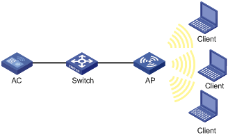
Configure a VLAN pool that comprises VLANs 2 through 5 for the AP to assign clients to different VLANs.
Figure 5 Network diagram
Configuration procedure
# Create WLAN ESS 1, configure the link type as hybrid, and enable the MAC VLAN function.
<AC> system-view
[AC] interface wlan-ess 1
[AC-WLAN-ESS1] port link-type hybrid
[AC-WLAN-ESS1] mac-vlan enable
[AC-WLAN-ESS1] quit
# Create service template 1, set the SSID to service, and bind WLAN-ESS 1 to the service template.
[AC] wlan service-template 1 clear
[AC-wlan-st-1] ssid service
[AC-wlan-st-1] bind wlan-ess 1
[AC-wlan-st-1] service-template enable
[AC-wlan-st-1] quit
# Create VLAN pool office, and add VLANs 2 through 5 to the VLAN pool.
[AC] vlan 2 to 5
[AC] wlan vlan-pool office
[AC-wlan-vp-office] vlan-id 2 to 5
[AC-wlan-vp-office] quit
# Create AP template named ap1.
[AC] wlan ap ap1 model WA3628i-AGN
[AC-wlan-ap-ap1] serial-id 210235A35U007B000010
# Bind the VLAN pool office to the service template on radio 2.
[AC-wlan-ap-ap1] radio 2
[AC-wlan-ap-ap1-radio-2] service-template 1 vlan-pool office
[AC-wlan-ap-ap1-radio-2] radio enable
Verifying the configuration
· Use the display wlan statistics client vlan-pool command to display the number of clients in each VLAN in the VLAN pool.
· Use the display wlan client command to display the VLAN to which a client belongs.
Configuring wireless location
Overview
Support for this feature depends on your device model. For more information, see About the H3C Access Controllers Configuration Guides.
Wireless location is a technology to locate, track and, monitor specific assets by using WiFi-based Radio Frequency Identification (RFID) and sensors. APs send collected Tag or MU messages to a location server. The location server performs location calculation and sends the results to the graphics software. You can view the location information of the assets in maps, forms, and reports provided by the software. The graphics software provides search, alert and query functions to facilitate your operations.
Wireless location can be applied to medical monitoring, asset management, and logistics, helping users effectively manage and monitor assets.
Architecture of the wireless location system
A wireless location system contains devices or sources to be located, location information receivers, and location systems.
· Devices or sources to be located include Tags (small, portable RFIDs, which are usually placed or glued to the assets to be located) of a location server company or Mobile Units (MU), and MUs (wireless terminals or devices running 802.11). The tags and MUs can send wireless messages periodically.
· Location information receivers include 802.11 APs.
· Location systems include the location server, calculation software of a location server company, and different types of graphics software.
Wireless location method
Before locating wireless devices, configure a wireless location method so that the AP can get an IP address of the location server:
· Dynamic wireless location—The AP obtains an IP address of the location server from packets sent from the location server. Only location servers of AeroScout support this method.
· Static wireless location—An IP address of the location server is manually configured on the AC.
Wireless locating process
A wireless location system can locate wireless clients, APs, rogue APs, rogue clients, Tags and other devices supporting WLAN protocols. All wireless devices except Tags will be identified as MUs by the wireless location system.
1. Located devices send Tag or MU messages
An RFID sends tag messages that contain channel information over different channels. The RFID periodically sends messages over the configured channels first and then sends tag messages over channels 1, 6, and 11 in turn periodically.
Standard wireless devices send MU messages. An MU message does not contain channel information, so an AP cannot filter MU messages by channel number. The work is done by the location server by using a certain algorithm and rules.
2. The AP collects Tag and MU messages
The working mode of an AP determines how it collects Tag and MU messages:
¡ When the AP operates in normal mode and is bound to an enabled wireless service, it can locate wireless clients associated or not associated with it or other wireless devices, including Tags. The wireless location system considers wireless clients associated with the AP as wireless clients, and considers wireless clients or other wireless devices not associated with the AP as unknown devices.
¡ When the AP operates in normal mode and is not bound to any wireless service or the wireless service is disabled, it can only locate wireless clients not associated with it or other wireless devices.
¡ When the AP operates in monitor mode or hybrid mode, it can locate wireless clients or other wireless devices that are not associated with it. As a best practice, do not enable this mode because frequent channel change might affect Tag locating performance.
For more information about monitor mode and hybrid mode, see "Configuring WLAN security."
The AP collects Tag and MU messages as follows:
· Upon receiving Tag messages (suppose that the Tags mode has been configured on the AC, and the location server has notified the AP to report Tag messages), the AP checks the Tag messages, encapsulates those passing the check and sends them to the location server. The AP encapsulates a Tag message by copying all its information (including message header and payload) except the multicast address and adding the BSSID, channel, timestamp, data rate, RSSI, SNR, and radio mode of the radio that received the Tag message.
· Upon receiving MU messages (suppose that the MUs mode has been configured on the AC, and the location server has notified the AP to report MU messages), the AP checks the messages, encapsulates those that pass the check and sends the messages to the location server. The AP encapsulates an MU message by copying its source address, Frame Control field, and Sequence Control field, and adding the BSSID, channel, timestamp, data rate, RSSI, SNR and radio mode of the radio that received the MU message.
· The location server calculates the locations of devices.
After receiving Tag and MU messages from APs, the location server uses an algorithm to calculate the locations of the devices according to the RSSI, SNR, radio mode and data rate carried in the messages, and displays the locations on the imported map. Typically, the location server can calculate the locations as long as there are more than three APs used to report Tag and MU messages.
Wireless location protocols
An AP supports the following wireless location protocols:
· AeroScout protocol—A protocol made by AeroScout for communications between location servers and APs. It supports both dynamic and static wireless location.
· OmniTrail protocol—A protocol made by OmniTrail for communications between location servers and APs. It supports only static wireless location.
· General wireless location protocol—A protocol made by H3C for communications between location servers and APs. It supports only static wireless location.
Wireless location rate limiting
The AeroScout protocol uses the dilution feature to reduce the MU messages when a WLAN is busy. However, when the network is not busy, the dilution feature might cause location failures that result from MU message loss.
To resolve this problem, you can configure wireless location rate limiting to prevent excessive MU messages from affecting the operation of the network and location server.
· AP-based rate limiting—Rate limits the MU messages from all APs.
· Client-based rate limiting—Rate limits the MU messages for each client.
CUPID location
Capturing User Positioning Including Direct path (CUPID) location is developed to precisely locate multiple clients. It is more immune to interferences, multipath effect, deployment density, and environment changes than other location methods.
Configuring wireless location
To perform wireless location, perform the following tasks on the location server and the device:
· On the location server—Configure whether to locate Tags or MUs, Tag message multicast address, and dilution factor on the location server. The APs are notified of these settings through configuration messages. For more information about location server and configuration parameters, see the location server manuals.
· On the wireless device—Configure a wireless location method, dynamic wireless location or static wireless location. The wireless location method determines the way the AP obtains an IP address of the location server and determines the functions you can configure.
Bind an AP to at least one wireless service and enable the wireless service when you configure wireless location on the AC.
Configuring static wireless location
For static wireless location, you can configure a dilution factor and dilution timeout for wireless location frames, but cannot configure the wireless location mode for the radios of an AP.
To configure static wireless location:
|
Step |
Command |
Remarks |
|
1. Enter system view. |
system-view |
N/A |
|
2. Set a protocol for wireless location. |
wlan rfid-tracking engine-type { aero-scout | general [ mode { fingerprint | cupid } ] | omnitrail } |
Optional. By default, the AeroScout protocol is used for wireless location. |
|
3. Set the minimum interval at which APs report client antenna changes. |
wlan rfid-tracking antenna-change-report min-interval value |
Optional. By default, APs report client antenna changes at a minimum interval of 10 seconds. This feature takes effect only when fingerprint location is enabled. |
|
4. Enable APs to send fingerprint location packets in CUPID packet format. |
wlan rfid-tracking fingerprint cupid-report enable |
Optional. By default, APs send fingerprint location packets in fingerprint packet format. |
|
5. Set the wireless location method to static. |
wlan rfid-tracking engine-detection static |
Optional. By default, the static wireless location method is used. |
|
6. Set the port number for the location server vendor. |
wlan rfid-tracking vendor-port vendor-port-value |
Optional. By default, the port number for the vendor is 1144. |
|
7. Specify the server port to which OmniTrail location packets are reported. |
wlan rfid-tracking omnitrail { data-port-2g port-number | data-port-5g port-number } |
Optional. By default, the port number is 0. |
|
8. Enable wireless location. |
wlan rfid-tracking enable |
By default, wireless location is disabled. |
|
9. Configure the rate at which the AP sends wireless location frames to the location server. |
wlan rfid-tracking rate-limit cir [ cbs cbs ] |
Optional. By default, wireless location frame sending rate is not limited. |
|
10. Configure the rate at which a client sends wireless location frames to the location server. |
wlan rfid-tracking client-rate-limit cir [ cbs cbs ] |
By default, client wireless location frame sending rate is not limited. |
|
11. Ignore AP frames or beacon frames. |
wlan rfid-tracking ignore { ap-frame | beacon } |
Optional. By default, AP frames and beacon frames are not ignored. |
|
12. Set an RSSI threshold for wireless location frames. |
wlan rfid-tracking rssi-threshold rssi-threshold |
Optional. By default, no RSSI threshold is configured. |
|
13. Set a dilution factor and dilution timeout for wireless location frames. |
wlan rfid-tracking dilution factor factor timeout timeout |
Optional. By default, no dilution factor and dilution timeout are configured. |
|
14. Enable AP reporting for CUPID location. |
wlan rfid-tracking cupid ap-report enable |
Optional. By default, AP reporting is disabled for CUPID location. Enable AP reporting before you configure CUPID location. |
|
15. Set the AP reporting interval. |
wlan rfid-tracking cupid ap-report interval interval |
Optional. By default, the AP reporting interval is 2 seconds. |
|
16. Set the RSSI threshold for unassociated client CUPID location. |
wlan rfid-tracking cupid unassociated-measurement rssi-threshold rssi |
Optional. By default, no RSSI threshold is specified for unassociated client CUPID location. |
|
17. Enable CUPID location for unassociated clients. |
wlan rfid-tracking cupid unassociated-measurement enable |
Optional. By default, CUPID location for unassociated clients is disabled. |
|
18. Enable raw frame reporting. |
wlan rfid-tracking raw-frame-report enable |
Optional. By default, raw frame reporting is enabled. This feature takes effect only when fingerprint location is enabled. |
|
19. Enable ignoring radio modes. |
wlan rfid-tracking ignore radio-mode |
Optional. By default, ignoring radio modes is enabled. |
|
20. Specify a multicast MAC address for Tags. |
wlan rfid-tracking tag-multicast-address mac-address |
Optional. By default, no multicast MAC address is specified for Tags. |
|
21. Specify the AP name and model, and enter AP template view. |
wlan ap ap-name [ model model-name [ id ap-id ] ] |
The AP model needs to be specified only when you create an AP template. |
|
22. Set an IPv4 address for the wireless location server. |
rfid-tracking engine-address engine-address |
By default, no IPv4 address is configured for the location server. |
|
23. Set the AP identifier for OmniTrail location. |
rfid-tracking omnitrail apid { ascii ascii-string | hex hex-string } |
Optional. By default, no identifier is specified for an AP. |
|
24. Enable channel scanning report suppression. |
rrm-report send-inhibitory enable |
Optional. Channel scanning report suppression is disabled. |
|
25. Return to system view. |
quit |
N/A |
|
26. Create an AP group and enter its view. |
wlan ap-group group-name |
Optional. By default, all APs belong to the default AP group default_group. |
|
27. Set an IPv4 address for the wireless location server. |
rfid-tracking engine-address engine-address |
By default, no IPv4 address is configured for the location server. |
|
28. Specify the type of devices to locate. |
rfid-tracking mode { all | mu | tag } |
By default, the type of wireless devices to locate is not specified. |
Configuring dynamic wireless location
For dynamic wireless location, you can configure the wireless location mode for the radio of an AP, but cannot configure the dilution factor, dilution timeout, and protocol type for wireless location frames.
To configure dynamic wireless location:
|
Step |
Command |
Remarks |
|
1. Enter system view. |
system-view |
N/A |
|
2. Set the protocol for wireless location to aero-scout. |
wlan rfid-tracking engine-type aero-scout |
Optional. By default, the AeroScout protocol is used for wireless location. |
|
3. Set the wireless location method to dynamic. |
wlan rfid-tracking engine-detection dynamic |
By default, the static wireless location method is used. |
|
4. Set the port number for the location server vendor. |
wlan rfid-tracking vendor-port vendor-port-value |
Optional. By default, the port number for the vendor is 1144. |
|
5. Enable wireless location. |
wlan rfid-tracking enable |
By default, wireless location is disabled. |
|
6. Set the rate at which the AP sends wireless location frames to the location server. |
wlan rfid-tracking rate-limit rate |
Optional. By default, wireless location frame sending rate is not limited. |
|
7. Ignore AP frames or beacon frames. |
wlan rfid-tracking ignore { ap-frame | beacon } |
Optional. By default, AP frames and beacon frames are not ignored. |
|
8. Set an RSSI threshold for wireless location frames. |
wlan rfid-tracking rssi-threshold rssi-threshold |
Optional. By default, no RSSI threshold is configured. |
|
9. Specify the AP name and model and enter AP template view. |
wlan ap ap-name [ model model-name [ id ap-id ] ] |
You must specify the model name when you create an AP template. |
|
10. Enable channel scanning report suppression. |
rrm-report send-inhibitory enable |
Optional. Channel scanning report suppression is disabled. |
|
11. Enter WLAN radio view. |
radio radio-id |
N/A |
|
12. Set the wireless location mode for the radio. |
rfid-tracking mode { all | mu | tag } |
By default, no wireless location mode is configured for the radio. |
After the configuration, the AP waits for the configuration message sent by the location server, and after receiving that message, starts to receive and report Tag and MU messages.
In addition, the AP reports its IP address change and reboot events to the location server so that the location server can respond in time. To report a reboot event after reboot, the AP must use the IP address and port information of the location server stored in its Flash. The AP maintains such information as follows:
· The AP updates the data in the Flash after receiving a configuration message. To protect the Flash, the AP does not update the Flash immediately, but waits for 10 minutes. If it receives another configuration message before the 10 minutes elapse, the AP only updates the configuration information in the cache, and when the 10-minute timer expires, saves the information in the Flash.
· If the AP reboots within 10 minutes after it receives the first configuration message, no server information is saved in the Flash, so it does not send a reboot message to the location server.
Displaying and maintaining wireless location
|
Task |
Command |
Remarks |
|
Display wireless location radio information. |
display wlan rfid-tracking radio [ ap ap-name radio radio-id ] [ | { begin | exclude | include } regular-expression ] |
Available in any view. |
Wireless location configuration example
Dynamic wireless location configuration example
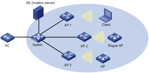
Network requirements
As shown in Figure 6, AP 1, AP 2, and AP 3 operate in normal mode, and send collected tag and MU messages to the AE (the location server). The AE performs location calculation and sends the results to the graphics software. The software displays location information for the rogue AP, APs, and clients in maps, forms, or reports.
Configuration procedure
1. Configure the AE server:
¡ Configure the IP addresses of AP 1, AP 2, and AP 3 on the AE, or select broadcast for the AE to discover APs.
¡ Configure wireless location settings on the AE.
2. Bind wireless services:
On the AC, bind wireless services to AP 1, AP 2, and AP 3. In this example, AP 1 is used for instance.
# Create a clear-type WLAN service template, set the SSID of the service template to service, and bind the WLAN-ESS interface to this service template.
<AC> system-view
[AC] wlan service-template 1 clear
[AC-wlan-st-1] ssid service
[AC-wlan-st-1] bind wlan-ess 1
[AC-wlan-st-1] authentication-method open-system
[AC-wlan-st-1] service-template enable
[AC-wlan-st-1] quit
# Create AP 1, set the serial ID for the AP, and bind service template 1 to radio 1.
[AC] wlan ap ap1 model WA2220-AG
[AC-wlan-ap-ap1] serial-id 210235A29G007C000020
[AC-wlan-ap-ap1] radio 1
[AC-wlan-ap-ap1-radio-1] service-template 1
[AC-wlan-ap-ap1-radio-1] radio enable
[AC-wlan-ap-ap1-radio-1] return
# Enable dynamic wireless location.
<AC> system-view
[AC] wlan rfid-tracking engine-detection dynamic
[AC] wlan rfid-tracking enable
[AC] wlan ap ap1
[AC-wlan-ap-ap1] radio 1
[AC-wlan-ap-ap1-radio-1] rfid-tracking mode all
[AC-wlan-ap-ap1-radio-1] return
3. Verify the configuration:
# Display wireless location radio information.
<AC> display wlan rfid-tracking radio
WLAN RFID Tracking
--------------------------------------------------------------------------------
AP Radio Mode
--------------------------------------------------------------------------------
ap1 1 MU/Tag
ap1 2 N/A
--------------------------------------------------------------------------------
# You can view the location information about the rogue AP, APs, and clients by maps, forms or reports provided by the graphics software.
Configuration guidelines
· To implement wireless location, configure a minimum of three APs to operate in monitor or hybrid mode.
· An AP monitors clients on different channels periodically. If the Tag message sending interval is configured as 1 second, the AP scans and reports Tag messages every half a minute. If higher location efficiency is required, you can set the Tag sending interval to the smallest value, 124 milliseconds on the AE.
Static wireless location configuration example
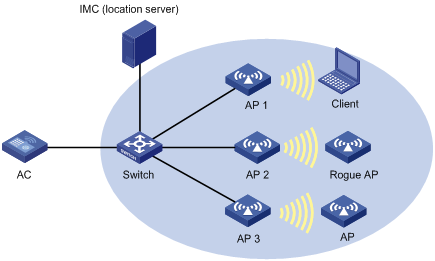
Network requirements
As shown in Figure 7, AP 1, AP 2, and AP 3 operate in normal mode, and send collected tag and MU messages to the IMC server (the location server). IMC performs location calculation and sends the results to the graphics software. The software displays location information for the rogue AP, APs, and clients in maps, forms, or reports.
Configuration procedure
1. Configure the IMC server:
¡ Configure the IP addresses of AP 1, AP 2, and AP 3 on IMC, or configure IMC to discover APs through broadcast.
¡ Configure wireless location settings on IMC.
2. Bind wireless services:
On the AC, bind wireless services to AP 1, AP 2, and AP 3. In this example, AP 1 is used for instance.
# Create a clear-type WLAN service template, set the SSID of the service template to service, and bind the WLAN-ESS interface to this service template.
<AC> system-view
[AC] wlan service-template 1 clear
[AC-wlan-st-1] ssid service
[AC-wlan-st-1] bind wlan-ess 1
[AC-wlan-st-1] authentication-method open-system
[AC-wlan-st-1] service-template enable
[AC-wlan-st-1] quit
# Create AP 1, set the serial ID for the AP, and bind service template 1 to radio 1.
[AC] wlan ap ap1 model WA2220-AG
[AC-wlan-ap-ap1] serial-id 210235A29G007C000020
[AC-wlan-ap-ap1] radio 1
[AC-wlan-ap-ap1-radio-1] service-template 1
[AC-wlan-ap-ap1-radio-1] radio enable
[AC-wlan-ap-ap1-radio-1] return
# Enable static wireless location.
<AC> system-view
[AC] wlan rfid-tracking engine-type general mode fingerprint
[AC] wlan rfid-tracking enable
# Set an RSSI threshold for wireless location frames to 15.
[AC] wlan rfid-tracking rssi-threshold 15
# Set an IPv4 address of the wireless location server to 192.168.10.10.
[AC] wlan ap ap1
[AC-wlan-ap-ap1] rfid-tracking engine-address 192.168.10.10
[AC-wlan-ap-ap1] quit
3. Verify the configuration:
Verify that you can view the location information about the rogue AP, APs, and clients on IMC.
Configuration guidelines
· To implement wireless location, configure a minimum of three APs to operate in monitor or hybrid mode.
· An AP monitors clients on different channels periodically. If the Tag message sending interval is configured as 1 second, the AP scans and reports Tag messages every half a minute. If higher location efficiency is required, you can set the Tag sending interval to the smallest value, 124 milliseconds on IMC.
Configuring multicast optimization
Support for this feature depends on the device model. For more information, see About the H3C Access Controllers Configuration Guides.
WLAN selects the lowest transmit rate for multicast packets and provides no multicast retransmission mechanism. Therefore, WLAN cannot meet the requirements of some multicast applications that are not delay sensitive but data-integrity sensitive such as HD VoD. The multicast optimization feature can solve these problems by enabling APs to convert multicasts packets to unicast packets, so WLAN can provide retransmission service and higher transmit rates for the converted unicast packets.
Unless otherwise specified, the unicast packets in this chapter refer to the wireless unicast packets that have the priority of video.
Figure 8 Multicast data transmission when multicast optimization is enabled
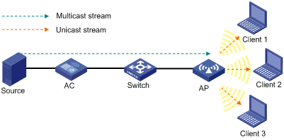
When multicast optimization is enabled, the AP listens to the IGMP reports and leave messages sent by clients. When the AP receives an IGMP report, it adds or updates a multicast optimization entry and updates the multicast source addresses allowed by the client (for IGMPv3 and MLDv2 packets). When the AP receives an IGMP leave message or when a multicast optimization entry ages out, the AP removes the entry. When the AP is disconnected from the AC, or when multicast optimization is disabled, all multicast optimization entries are removed.
After creating multicast entries, the AP listens to non IGMP and MLD multicast packets sent from the multicast source to clients, and matches the multicast address of the packets to the multicast optimization entries. If a match is found, the AP converts the multicast packets to unicast packets and sends the unicast packets to all the clients in the multicast entries. If no match is found, the AP directly sends the multicast packets.
To avoid performance degradation, you can configure the maximum number of clients that multicast optimization can support. When the maximum number is reached, the AC takes either of the following actions as configured:
· Halt—A new client can join a multicast group and receive multicast packets, and a multicast optimization entry can be created for the client. However, the multicast optimization function for all clients in the multicast group becomes invalid. When the number of clients drops below the upper limit, the multicast optimization function takes effect again.
· Reject-client—A new client can join a multicast group, but no new multicast optimization entries can be created. If multicast optimization entries have been created for other clients in the multicast group, the client cannot receive multicast packets. If not, the client can receive multicast packets.
Configuring multicast optimization
Enable IGMP snooping on the AC before enabling multicast optimization and configure the aging time of multicast optimization entries to be greater than the aging time of IGMP snooping dynamic member ports.
To enable multicast optimization to operate properly in a WLAN roam environment, make sure the multicast optimization function is enabled with the multicast optimization enable command on all ACs on IACTP tunnels.
To configure multicast optimization:
|
Step |
Command |
Remarks |
|
1. Enter system view. |
system-view |
N/A |
|
2. Enter service template view. |
wlan service-template service-template-number { clear | crypto } |
N/A |
|
3. Enable multicast optimization. |
multicast optimization enable |
By default, the multicast optimization function is disabled. |
|
4. Exit to system view. |
quit |
N/A |
|
5. Set the maximum number of clients supported by multicast optimization. |
wlan multicast optimization threshold threshold-value |
Optional. The default number is 6. A client can join up to eight multicast groups. If a client joins multiple multicast groups, the client is counted as multiple clients in multicast optimization statistics. For example, if a client has joined two multicast groups, the client is counted as two clients in the multicast optimization statistics. |
|
6. Set the action to take when the maximum number of clients supported by multicast optimization is reached. |
wlan multicast optimization threshold-action { halt | reject-client } |
Optional. The default action is halt. If you configure the halt action first, and then configure the reject-client action, the existing multicast optimization entries still take effect. |
|
7. Set the aging time for multicast optimization entries. |
wlan multicast optimization aging-time time |
Optional. By default, the aging time is 260 seconds. |
Displaying and maintaining multicast optimization
|
Task |
Command |
Remarks |
|
Display multicast optimization information. |
display wlan multicast optimization { all | ap-name ap-name radio radio-id } [ | { begin | exclude | include } regular-expression ] |
Available in any view. |
Multicast optimization configuration example
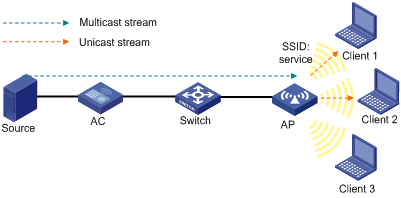
Network requirements
As shown in Figure 9, enable multicast optimization for the AP to convert multicast packets to unicast packets for up to two clients.
Configuration procedure
1. Configure the AC:
Complete wireless configurations on the AC. For more information, see "Configuring WLAN access."
Enable the multicast function in VLAN 1 on the AC and complete multicast configurations. For more information, see IP Multicast Configuration Guide.
# Enable multicast optimization.
<AC> system-view
[AC] wlan service-template 1 clear
[AC-wlan-st-1] ssid service
[AC-wlan-st-1] multicast optimization enable
[AC-wlan-st-1] quit
# Set the aging time for multicast optimization entries to 300 seconds.
[AC] wlan multicast optimization aging-time 300
# Set the maximum number of clients supported by multicast optimization to 2.
[AC] wlan multicast optimization threshold 2
# Configure the AC to reject new clients when the maximum number of clients supported by multicast optimization is reached.
[AC] wlan multicast optimization threshold-action reject-client
2. Verify the configuration:
Client 1 and Client 2 access the SSID named service through a radio on the AP and join a multicast group. Execute the display wlan multicast optimization all command to view the multicast optimization information. The output shows that the multicast optimization function operates properly when Client 1 and Client 2 are in the group. When Client 3 joins the multicast group, no multicast optimization entry can be added for Client 3, because the maximum number of clients supported by multicast optimization has been reached.
Configuring spectrum analysis
Support for spectrum analysis depends on the AP model. For more information, see About the H3C Access Controllers Configuration Guides.
For more information about WIDS, see "Configuring WLAN IDS."
To configure spectrum analysis, you need to buy a license and register it first. You can buy a Software License Certificate to get a license. The certificate provides an license key to register RFP (Radio Frequency Prevention). For more information about license registration, see H3C Series Access Controllers License Registration and Activation Guide. For more information about managing a license, see Fundamentals Configuration Guide.
WLAN systems operate on shared bands. Many devices, such as microwave ovens, cordless phones, and Bluetooth devices also operate on these bands and can negatively affect the WLAN systems.
The spectrum analysis feature is designed to solve this problem. Spectrum analysis delivers the following functions:
· Identifies 12 types of interferences and provides interference device reports.
· Calculates the number of interferences on each channel and average and worst channel quality, and provides channel quality reports.
· The AP collects Fast Fourier Transform (FFT) data, including frequency, FFT power, maximum power, and FFT duty cycle, and sends the data to the NMS through the AC.
· With RRM collaboration enabled, if the detected channel quality is lower than the threshold, the AC automatically adjusts the working channel upon detecting a channel with a higher quality.
Administrators can view the interference information on the AC, or view real-time spectrum analysis data on the NMS to locate and remove the interferences.
Configuration task list
|
Task |
Remarks |
|
Required |
|
|
Required |
|
|
Optional |
|
|
Optional |
Configuring the operating mode for an AP
The channels that an AP can detect depend on the operating mode of the AP:
· When operating in normal mode, an AP can only detect interference devices and channel quality, and collect FFT data for its working channel.
· When operating in monitor or hybrid mode, the channels that an AP can detect depend on the scan channel command. If you configure the scan channel auto command, the AP detects interference devices and channel quality, and collects FFT data for the channels supported by the country code. If you configure the scan channel all command, the AP detects interference devices and channel quality, and collects FFT data for all channels.
As a best practice, enable spectrum analysis for APs operating in monitor or hybrid mode.
For information about how to configure the operating mode for an AP, see "Configuring WLAN IDS."
Enabling spectrum analysis
When spectrum analysis is enabled, an AP monitors interference devices and channel quality and collects FFT data.
To enable spectrum analysis:
|
Step |
Command |
Remarks |
|
1. Enter system view. |
system-view |
N/A |
|
2. Enter WLAN RRM view. |
wlan rrm |
N/A |
|
3. Enable spectrum analysis globally. |
· On 5 GHz radios: · On 2.4 GHz radios: |
By default, spectrum analysis is disabled globally. |
|
4. Set the type of interferences to be detected. |
· On 5 GHz radios: · On 2.4 GHz radios: |
Optional. By default, all interferences are to be detected. |
|
5. Return to system view. |
quit |
N/A |
|
6. Specify the AP name and its model number and enter AP template view. |
wlan ap ap-name [ model model-name [ id ap-id ] ] |
Specify the model name only when you create a new AP template. |
|
7. Enter radio view. |
radio radio-number [ type { dot11a | dot11an | dot11b | dot11g | dot11gn } ] |
N/A |
|
8. Enable spectrum analysis. |
spectrum-analysis enable |
By default, spectrum analysis is disabled. Spectrum analysis takes effect on the specified radio only when it is enabled both globally and on a radio. |
Enabling SNMP traps
This function enables the AC to send SNMP traps to the NMS when detecting an interference device or when detecting the channel quality is lower than the alarm threshold.
To enable SNMP trap sending when an interference device is detected:
|
Step |
Command |
Remarks |
|
1. Enter system view. |
system-view |
N/A |
|
2. Enter WLAN RRM view. |
wlan rrm |
N/A |
|
3. Enable the AC to send SNMP traps to the NMS when detecting an interference device. |
· On 5 GHz radios: · On 2.4 GHz radios: |
Optional. By default, the AC sends SNMP traps to the NMS when detecting an interference device. |
|
4. Enable the AC to send SNMP traps to the NMS when detecting a specified interference device. |
· On 5 GHz radios: · On 2.4 GHz radios: |
Optional. By default, the AC sends SNMP traps to the NMS when detecting one of the 12 interference device types. Before configuring this command, use the dot11a spectrum-analysis device device-type or dot11bg spectrum-analysis device device-type command to specify the type of interference to be detected. Otherwise, this command does not take effect. |
To enable SNMP traps when the channel quality is lower than the channel quality alarm threshold:
|
Step |
Command |
Remarks |
|
1. Enter system view. |
system-view |
N/A |
|
2. Enter WLAN RRM view. |
wlan rrm |
N/A |
|
3. Set the channel quality alarm threshold. |
· On 5 GHz radios: · On 2.4 GHz radios: |
Optional. By default, the channel quality alarm threshold is 35. |
|
4. Enable the AC to send SNMP traps to the NMS when the channel quality is lower than the channel quality alarm threshold. |
· On 5 GHz radios: · On 2.4 GHz radios: |
Optional. By default, the AC sends SNMP traps to the NMS when the channel quality is lower than the channel quality alarm threshold. |
Enabling spectrum analysis to trigger channel adjustment
This function enables the AC to start calculating the channel quality, and switches to a new channel with a higher quality when the channel quality is lower than the sensitivity level.
Before configuring this function, enable automatic channel selection with the channel auto command, and enable DFS. Otherwise, this function does not take effect. For more information about the channel auto command, see WLAN Command Reference. For more information about DFS, see "Configuring WLAN RRM."
To enable spectrum analysis to trigger channel adjustment:
|
Step |
Command |
Remarks |
|
1. Enter system view. |
system-view |
N/A |
|
2. Enter WLAN RRM view. |
wlan rrm |
N/A |
|
3. Set the sensitivity level that triggers channel adjustment. |
· On 5 GHz radios: · On 2.4 GHz radios: |
Optional. By default, the sensitivity level that triggers channel adjustment is medium. |
|
4. Enable spectrum analysis to trigger channel adjustment. |
· On 5 GHz radios: · On 2.4 GHz radios: |
By default, spectrum analysis does not trigger channel adjustment. |
Displaying and maintaining spectrum analysis
|
Task |
Command |
Remarks |
|
Display information about the detected non-802.11n interferences. |
display wlan spectrum-analysis device [ ap ap-name ] |
Available in any view. |
|
Display channel quality information. |
display wlan spectrum-analysis channel-quality [ ap ap-name ] |
Available in any view. |
Spectrum analysis configuration example
Network requirements
As shown in Figure 10, AP 1 is operating in normal mode to provide WLAN access services. AP 2 is operating in monitor mode to detect interferences, channel quality, and FFT data. If AP 2 detects an microwave oven or Bluetooth device, AP 2 notifies the AC, which sends alarms to the NMS.
Configuration procedure
# Configure AP 1 to operate in normal mode. For more information, see "WLAN Access Configuration."
# Configure AP 2 to operate in monitor mode, and enable spectrum analysis on radio 2 of AP 2.
<AC> system-view
[AC] wlan ap ap2 model WA2620-AGN
[AC-wlan-ap-ap2] serial-id 210235A29G007C000022
[AC-wlan-ap-ap2] work-mode monitor
[AC-wlan-ap-ap2] radio 2 type dot11gn
[AC-wlan-ap-ap2-radio-2] spectrum-analysis enable
[AC-wlan-ap-ap2-radio-2] radio enable
[AC-wlan-ap-ap2-radio-2] quit
[AC-wlan-ap-ap2] quit
# Enable spectrum analysis globally on 2.4 GHz radios.
[AC] wlan rrm
[AC-wlan-rrm] dot11bg spectrum-analysis enable
# Configure the AP to detect all interferences on 2.4 GHz radios. (Enabled by default. Optional.)
[AC-wlan-rrm] dot11bg spectrum-analysis device all
# Enable the AC to send alarms to the NMS when a microwave oven or Bluetooth is detected on 2.4 GHz radios.
[AC-wlan-rrm] dot11bg spectrum-analysis trap device enable
[AC-wlan-rrm] undo dot11bg spectrum-analysis trap device all
[AC-wlan-rrm] dot11bg spectrum-analysis trap device bluetooth
[AC-wlan-rrm] dot11bg spectrum-analysis trap device microwave
[AC-wlan-rrm] return
Verifying the configuration
· Execute the display wlan spectrum-analysis device command to display information about the non-802.11 interferences detected by AP 2.
· Execute the display wlan spectrum-analysis channel-quality command to display channel quality information.
Configuring MAC-BAC
Support for this feature depends on the device model. For more information, see About the H3C Access Controllers Configuration Guides.
Overview
MAC-BAC provides an AC deployment method to simplify AC management.
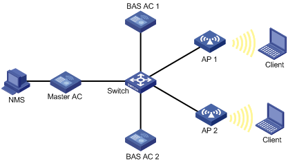
MAC-BAC defines a master AC and multiple BAS ACs. As shown in Figure 11, the master AC manages the BAS ACs, and the BAS ACs provide WLAN access and authentication.
The master AC resides between the BAS ACs and the authentication server. Among the ACs, only the master AC communicates with the authentication server, and the BAS ACs communicate with the master AC to complete authentication. From the authentication server's perspective, there is only one AC on the WLAN.
Wireless devices cannot serve as a master AC.
MAC-BAC operating mechanism
Before a master AC can manage the BAS ACs, it must establish a tunnel with each BAS AC. After the tunnels are established, each BAS AC reports local information to the master AC, including IP address used to establish a tunnel with APs, IP address of the BAS AC, the number of online APs, and IP addresses of clients associated with the APs.
The master AC and BAS ACs exchange information through tunnels.
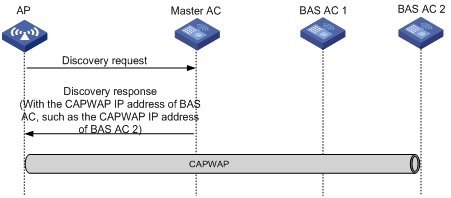
MAC-BAC operates as follows:
1. The master AC establishes tunnels with BAS ACs.
2. An AP obtains the IP address of the master AC from the Option field in the reply sent by the DHCP server (recommended).
An AP can also obtain an IP address in other ways.
3. The AP unicasts a discovery request to the master AC.
4. The master AC returns a discovery response that contains the CAPWAP IP address of the BAS AC with the lowest workload.
5. The AC establishes a tunnel with the specified BAS AC.
6. The BAS AC reports the AP information to the master AC so that the master AC can manage the BAS ACs.
Figure 12 Network diagram
|
|
NOTE: As a best practice, use Option to obtain the IP address of the master AC. |
Configuring a BAS AC
If the BAS AC function is disabled, a BAS AC is an ordinary AC.
To configure a BAS AC:
|
Step |
Command |
Remarks |
|
1. Enter system view. |
system-view |
N/A |
|
2. Enable the BAS AC function. |
wlan bas-ac enable |
By default, the BAS AC function is disabled. |
|
3. Assign a master AC to the BAS AC. |
wlan master-ac { ip ipv4-address | ipv6 ipv6-address } port port-number [ authentication { cipher | simple } authentication-key ] |
By default, no master AC is assigned to the BAS AC. |
|
4. Specify the CAPWAP IP address. |
wlan capwap address { ip ip-address | ipv6 ipv6-address } |
By default, no CAPWAP IP address is specified. |
|
5. Specify an IP address for the BAS AC to connect to the master AC. |
wlan bas-ac ip ip-address |
By default, no IP address is specified for the BAS AC. |
|
6. Specify the interval at which the BAS AC sends connection requests to the master AC. |
wlan bas-ac retry-interval seconds |
Optional. By default, the interval is 15 seconds. |
|
7. Synchronize the configurations of the current BAS AC to other BAS ACs in the MAC-BAC network. |
wlan bas-ac synchronize-configuration |
Optional. |
|
|
NOTE: The IP address for the BAS AC to connect to the master AC and the CAPWAP IP address can be the same. |
MAC-BAC configuration example
Network requirements
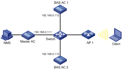
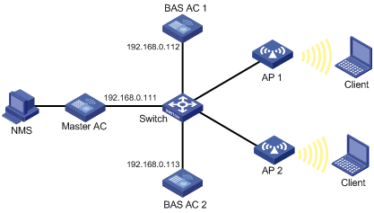
As shown in Figure 13, configure MAC-BAC so that the master AC assigns the BAS AC with the lightest workload to the AP. The maximum number of APs that BAS AC 1 and BAS AC 2 can manage is 1024 and 192, respectively. In this example, BAS AC 1 has the lowest workload.
Configuration procedure
1. Configure the master AC (wireless devices cannot serve as a master AC):
# Enable the master AC function.
<Master AC> system-view
[Master AC] wlan master-ac enable
# Enable the DHCP service, add network 192.168.0.0/24 to DHCP pool 0, configure Option 43 to specify the master AC address 192.168.0.111 (the last four bytes 0a8006f) in address pool 0.
[Master AC] dhcp enables
[Master AC] dhcp server ip-pool 0
[Master AC-dhcp-pool-0] network 192.168.0.0 24
[Master AC-dhcp-pool-0] option 43 hex 8007000001c0a8006f
2. Configure BAS AC 1:
# Enable the BAS AC function.
<BAS AC1> system-view
[BAS AC1] wlan bas-ac enable
# Set the IP address of the master AC to 192.168.0.111, and set the CAPWAP IP to 192.168.0.112.
[BAS AC1] wlan master-ac ip 192.168.0.111
[BAS AC1] wlan capwap address ip 192.168.0.112
# Set the IP address of BAS AC 1 to 192.168.0.112.
[BAS AC1] wlan bas-ac ip 192.168.0.112
# Enable the auto AP function, and create an AP template named ap1.
[BAS AC1] wlan enable
[BAS AC1] wlan auto-ap enable
[BAS AC1] wlan ap ap1 model WA2620i-AGN
[BAS AC1-wlan-ap-ap1] serial-id auto
3. Configure BAS AC 2:
# Enable the BAS AC function.
<BAS AC2> system-view
[BAS AC2] wlan bas-ac enable
# Set the IP address of the master AC to 192.168.0.111, and set the CAPWAP IP address to 192.168.0.113.
[BAS AC2] wlan master-ac ip 192.168.0.111
[BAS AC2] wlan capwap address ip 192.168.0.113
# Set the IP address of BAS AC 2 to 192.168.0.113.
[BAS AC2] wlan bas-ac ip 192.168.0.113
# Enable the auto AP function, and create an AP template named ap1.
[BAS AC2] wlan enable
[BAS AC2] wlan auto-ap enable
[BAS AC2] wlan ap ap1 model WA2620i-AGN
[BAS AC2-wlan-ap-ap1] serial-id auto
Verifying the configuration
Use the display wlan bas-ac command on the master AC to display detailed information about the BAS AC.
[Master AC-dhcp-pool-0] display wlan bas-ac verbose
MAC address :000f-e212-ff01
IP address :192.168.0.112
CAPWAP IP address :192.168.0.112
CAPWAP IPv6 address :NA
AP count :1
Maximum AP capacity :1024
MAC address :80f6-2e7d-1eb9
IP address :192.168.0.113
CAPWAP IP address :192.168.0.113
CAPWAP IPv6 address :NA
AP count :0
Maximum AP capacity :192
The output shows that AP 1 has been connected to BAS AC 1.
Hotspot-based BAS AC assignment configuration example
Network requirements
As shown in Figure 14, configure the hotspot-based BAS AC assignment function so that the master AC assigns AP 1 and AP 2 to the same BAS AC.
Configuration procedure
1. Configure the master AC (wireless devices do not support the master AC function):
# Enable the master AC function.
<Master AC> system-view
[Master AC] wlan master-ac enable
# Enable the DHCP service, add network 192.168.0.0/24 to DHCP pool 0, configure Option 43 to specify the master AC address 192.168.0.111 (the last four bytes 0a8006f) in address pool 0.
[Master AC] dhcp enable
[Master AC] dhcp server ip-pool 0
[Master AC-dhcp-pool-0] network 192.168.0.0 24
[Master AC-dhcp-pool-0] option 43 hex 8007000001c0a8006f
[Master AC-dhcp-pool-0] quit
# Create an AP list, and add MAC addresses 000f-e323-e221 and 000f-e323-5432 to the list.
[Master AC] wlan ap-list list1
[Master AC-ap-list-list1] mac-address 000f-e323-e221
[Master AC-ap-list-list1] mac-address 000f-e323-5432
[Master AC-ap-list-list1] quit
# Assign all APs in the AP list to one BAS AC.
[Master AC] wlan load-balance ap ap-list list1
2. Configure BAS AC 1:
# Enable the BAS AC function.
<BAS AC1> system-view
[BAS AC1] wlan bas-ac enable
# Set the IP address of the master AC to 192.168.0.111, and set the CAPWAP IP address to 192.168.0.112.
[BAS AC1] wlan master-ac ip 192.168.0.111
[BAS AC1] wlan capwap address ip 192.168.0.112
# Set the IP address of BAS AC 1 to 192.168.0.112.
[BAS AC1] wlan bas-ac ip 192.168.0.112
# Enable the auto AP function, and create an AP template named ap1.
[BAS AC1] wlan enable
[BAS AC1] wlan auto-ap enable
[BAS AC1] wlan ap ap1 model WA2620i-AGN
[BAS AC1-wlan-ap-ap1] serial-id auto
3. Configure BAS AC 2:
# Enable the BAS AC function.
<BAS AC2> system-view
[BAS AC2] wlan bas-ac enable
# Set the IP address of the master AC to 192.168.0.111, and set the CAPWAP IP address to 192.168.0.113.
[BAS AC2] wlan master-ac ipv4 192.168.0.111
[BAS AC2] wlan capwap address ip 192.168.0.113
# Set the IP address of BAS AC 2 to 192.168.0.113.
[BAS AC2] wlan bas-ac ip 192.168.0.113
# Enable the auto AP function, and create an AP template named ap1.
[BAS AC2] wlan enable
[BAS AC2] wlan auto-ap enable
[BAS AC2] wlan ap ap1 model WA2620i-AGN
[BAS AC2-wlan-ap-ap1] serial-id auto
Verifying the configuration
Use the display wlan bas-ac command to display detailed information about the BAS AC.
[Master AC] display wlan bas-ac verbose
MAC address :000f-e212-ff01
IP address :192.168.0.112
CAPWAP IP address :192.168.0.112
CAPWAP IPv6 address :NA
AP count :2
Maximum AP capacity :1024
MAC address :80f6-2e7d-1eb9
IP address :192.168.0.113
CAPWAP IP address :192.168.0.113
CAPWAP IPv6 address :NA
AP count :0
Maximum AP capacity :192
The output shows that AP 1 and AP 2 have been connected to the same BAS AC.
Configuring a guest access tunnel
Support for this feature depends on the device model. For more information, see About the H3C Access Controllers Configuration Guides.
A guest access tunnel redirects guest traffic to the external network of a company, providing WLAN access for guests and ensuring data security in the external network at the same time.
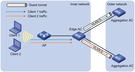
The guest access tunnel function is realized through an aggregation AC and an edge AC. The edge AC is deployed in the internal network to provide access and authentication services to internal users. The aggregation AC is deployed in the external network to process guest traffic. After a guest access tunnel is established between the edge AC and aggregation AC, guests go online through the specified guest VLAN, and guest traffic is forwarded to the aggregation AC.
Guest access tunnels support NAT traversal. If a NAT device is deployed between the edge AC and the aggregation AC, a guest access tunnel can still be established.
Figure 15 Network diagram
Configuring a guest access tunnel
Configuration restrictions and guidelines
When you configure a guest access tunnel, follow these restrictions and guidelines:
· If there are multiple guest access tunnels, each of them must belong to a different VLAN.
· The device supports at most 512 guest access tunnels. You can establish a guest access tunnel by specifying only IPv4 addresses.
· Configure the same guest VLAN on both the edge AC and the aggregation ACs. For example, if you configure VLAN 1, VLAN 2, VLAN 3, and VLAN 4 on the edge AC, and configure VLAN 2 and VLAN 3 on the aggregation AC, you must configure VLAN 2 or VLAN 3 as the guest VLAN.
VLANs that can be configured as guest VLAN include:
¡ VLANs specified in WLAN-ESS interface view.
¡ VLANs specified when you bind a service template.
¡ VLANs assigned by the VLAN pool.
¡ VLANs authorized by the authentication server.
The priorities of these VLANs are in ascending order. VLAN specified when you bind a service template and VLAN assigned by the VLAN pool have the same priority.
Configuration procedure
To establish a guest access tunnel, you must configure both an aggregation AC and an edge AC.
After you complete the configuration, the aggregation AC and edge AC communicate with each other by following these steps:
1. The edge AC sends a keep-alive request to the aggregation AC.
2. Upon receiving the request, the aggregation AC determines whether the source IP address of the request belongs to one of the edge ACs configured on it. If it does, the aggregation AC sends a response and a guest access tunnel is established.
3. The edge AC sends keep-alive requests to the aggregation AC at a specific interval.
¡ If the edge AC does not receive any response from the aggregation AC after three successive attempts, the edge AC terminates the guest access tunnel.
¡ If the aggregation AC does not receive any keep-alive request three times the interval, it terminates the guest access tunnel.
|
|
NOTE: · An edge AC can establish guest access tunnels with multiple aggregation ACs, but it cannot use different IP addresses to build tunnels with one aggregation AC. · If several IP addresses configured on the edge AC belong to one aggregation AC, the aggregation AC uses the destination IP address of the first keep-alive request to establish a guest access tunnel with the edge AC. |
Configuring an aggregation AC on an edge AC
|
Step |
Command |
Remarks |
|
1. Enter system view. |
system-view |
N/A |
|
2. Specify the current AC as the edge AC. |
wlan guest-tunnel edge-ac |
N/A |
|
3. Configure an aggregation AC on the edge AC. |
aggregation-ac ip ipv4-address source ip ipv4-address vlan vlan-id-list |
By default, no aggregation AC information is available on the edge AC. |
|
4. Set the interval at which the edge AC sends keep-alive requests. |
keep-alive time-interval |
Optional. By default, the interval at which the edge AC sends keep-alive requests is 10 seconds. |
Configuring an edge AC on an aggregation AC
|
Step |
Command |
Remarks |
|
1. Enter system view. |
system-view |
N/A |
|
2. Specify the current AC as the aggregation AC. |
wlan guest-tunnel aggregation-ac |
N/A |
|
3. Configure an edge AC on the aggregation AC. |
edge-ac ip ipv4-address vlan vlan-id-list |
By default, no edge AC information is available on the aggregation AC. |
Displaying and maintaining guest access tunnels
|
Task |
Command |
Remarks |
|
Displays configuration and status of guest access tunnels. |
display wlan guest-tunnel { all | ip ipv4-address } [ | { begin | exclude | include } regular-expression ] |
Available in any view. |
|
Delete guest access tunnels. |
reset wlan guest-tunnel { all | ip ipv4-address } |
Available in user view. |
Guest access tunnel configuration example
Network requirements
As shown in Figure 16, AC 1 is an edge AC and AC 2 is an aggregation AC. Configure a guest access tunnel so that guest traffic is separated from the traffic of the internal network.
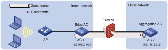
Configuration procedure
1. Configure AC 1:
# Specify AC 1 as the edge AC.
<AC1> system-view
[AC1] wlan guest-tunnel edge-ac
# Specify AC 2 as the aggregation AC and VLAN 5 as the guest VLAN.
[AC1-wlan-edge-ac] aggregation-ac ip 192.168.2.3 source ip 192.168.2.1 vlan 5
# Create a WLAN service template, set the SSID of this service template to guest, and bind the WLAN-ESS interface to the template.
[AC1] wlan service-template 1 clear
[AC1-wlan-st-1] ssid guest
[AC1-wlan-st-1] bind wlan-ess 1
[AC1-wlan-st-1] service-template enable
# Create an AP template.
[AC1] wlan ap ap1 model WA2620E-AGN
[AC1-wlan-ap-ap1] serial-id 210235A35U007B000010
# Bind the AP template to radio 2 and specify VLAN 5 as the VLAN through which the clients go online.
[AC1-wlan-ap-ap1-radio-2] service-template 1 vlan-id 5
[AC1-wlan-ap-ap1-radio-2] radio enable
2. Configure AC 2:
# Specify AC 2 as the aggregation AC.
<AC2> system-view
[AC2] wlan guest-tunnel aggregation-ac
# Specify AC 1 as the edge AC and VLAN 5 as the guest VLAN.
[AC2-wlan-aggregation-ac] edge-ac ip 192.168.2.1 vlan 5
Verifying the configuration
1. Execute the display wlan guest-tunnel all command on AC 1 and AC 2 to display the status of the guest access tunnel.
<AC1> display wlan guest-tunnel all
Guest-Tunnel Information
Local Mode: Edge AC Tunnel Count: 1
-------------------------------------------------------------------------------
Peer IP Address Local IP Address VLAN State Interface
-------------------------------------------------------------------------------
192.168.2.3 192.168.2.1 5 Up WLAN-Tunnel9
-------------------------------------------------------------------------------
<AC2> display wlan guest-tunnel all
Guest-Tunnel Information
Local Mode: Aggregation AC Tunnel Count: 1
-------------------------------------------------------------------------------
Peer IP Address VLAN State Interface
-------------------------------------------------------------------------------
192.168.2.1 5 Up WLAN-Tunnel9
-------------------------------------------------------------------------------
The output shows that the guest access tunnel is in Up state.
2. Execute the display interface wlan-tunnel command to view information about tunnel interfaces.
<AC1> display interface WLAN-TUNNEL
WLAN-Tunnel9 current state: UP
IP Packet Frame Type: PKTFMT_ETHNT_2, Hardware Address: 000f-e207-f2e0
Description: WLAN-Tunnel9 Interface
PVID: 1
Port link-type: trunk
VLAN passing : 5
VLAN permitted: 5
Trunk port encapsulation: IEEE 802.1q
Port priority: 0
Last clearing of counters: Never
Last 300 seconds input rate: 26 bytes/sec, 208 bits/sec, 0 packets/sec
Last 300 seconds output rate: 0 bytes/sec, 0 bits/sec, 0 packets/sec
10464620 packets input, 1476008950 bytes, 0 drops
10562630 packets output, 1499509010 bytes, 0 drops
<AC2> display interface WLAN-TUNNEL
WLAN-Tunnel9 current state: UP
IP Packet Frame Type: PKTFMT_ETHNT_2, Hardware Address: 000f-e207-f2e0
Description: WLAN-Tunnel9 Interface
PVID: 1
Port link-type: trunk
VLAN passing : 5
VLAN permitted: 5
Trunk port encapsulation: IEEE 802.1q
Port priority: 0
Last clearing of counters: Never
Last 300 seconds input rate: 0 bytes/sec, 0 bits/sec, 0 packets/sec
Last 300 seconds output rate: 9 bytes/sec, 72 bits/sec, 0 packets/sec
10562630 packets input, 1499509010 bytes, 0 drops
10464620 packets output, 1476008950 bytes, 0 drops
The output shows that VLAN 5 is in the list of permitted VLAN of WLAN-ESS TUNNEL interfaces on AC 1 and AC 2. The number of sent packets on the WLAN-ESS TUNNEL interface on AC 1 is the same as the number of received packets on the WLAN-ESS TUNNEL interface on AC 2. AC 1 forwarded guest traffic to AC 2.
3. Execute the display wlan client command to display detailed information about the guests.
The guests go online through VLAN 5.
Configuring Bonjour gateway
Support for this feature depends on the device model. For more information, see About the H3C Access Controllers Configuration Guides.
Bonjour is a set of zero configuration network protocols developed by Apple Inc based on Multicast DNS (mDNS) services. Bonjour is designed to make network configuration easier for users. It enables Apple devices to automatically advertise service information and enables clients to automatically discover Apple devices without obtaining information about the devices.
However, Bonjour supports only link-local multicast addresses. To address this issue, the AC can act as a Bonjour gateway to manage clients and devices providing services and forward mDNS packets across VLANs, enabling Bonjour to be applied in large scale networks.
Benefits
Bonjour gateway provides the following benefits:
· mDNS traffic control.
· User-defined Bonjour policies to restrict services that can be used by clients.
· Inter-VLAN forwarding of mDNS packets, enhancing network availability.
· Bonjour policy application in views of multiple levels.
Working mechanism
|
|
IMPORTANT: · The Bonjour gateway discards queries received from the wired network. · The Bonjour gateway filters queries and responses according to user-defined Bonjour policies. This section focuses on only the Bonjour gateway working mechanism. For more information about Bonjour policies, see "Configuring a Bonjour policy." |
Bonjour service advertisement snooping
The service devices send Bonjour responses to advertise their supporting services. Upon receiving the Bonjour responses, the AC creates a service-device mapping table to store service information about the service devices. When a client queries for a service, the Bonjour gateway searches the service-device mapping table and sends a response to the client.
As shown in Figure 17, Bonjour service advertisement snooping operates as follows:
1. Apple TV and Print send Bonjour responses to advertise their supporting services.
2. Upon receiving the Bonjour responses, the AC creates a service-device mapping table to store service information about Apple TV and Print.
3. iPad queries for the service of Apple TV or Print and the AC sends a response to iPad.
Figure 17 Bonjour service advertisement snooping
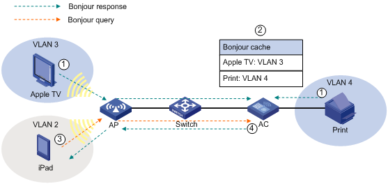
Bonjour query snooping and response
When a client queries for a service that is not in the service-device mapping table, the Bonjour gateway forwards the query. After receiving a response, the Bonjour gateway adds the service information to the service-device mapping table and forwards the response to the client.
As shown in Figure 18, Bonjour query snooping and response operates as follows:
1. iPad queries for the printing service, and the AP sends the query to the AC through the CAPWAP tunnel.
2. The AC forwards the query to the configured VLANs because it does not find any printing service entry in the service-device mapping table.
3. Upon receiving the query, the print service sends a response to the AC.
4. The AC adds the service information to the service-device mapping table and forwards the response to iPad.
The AC can respond by searching the service-device mapping table next time when a client queries the printing service.
Figure 18 Bonjour query snooping and response
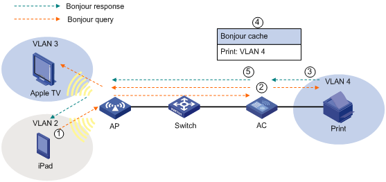
Configuring Bonjour gateway
The Bonjour gateway supports centralized forwarding, local forwarding, and policy-based forwarding.
Enable multicast optimization on the Bonjour gateway for media traffic services such as video and audio.
Enabling Bonjour gateway
Bonjour gateway takes effect only after you enable it both globally and for an AP. You can enable Bonjour gateway for an AP in AP template view or AP group view.
To enable Bonjour gateway globally:
|
Step |
Command |
Remarks |
|
1. Enter system view. |
system-view |
N/A |
|
2. Enable Bonjour gateway globally. |
wlan bonjour-gateway enable |
By default, Bonjour gateway is disabled globally. |
To enable Bonjour gateway for an AP:
|
Step |
Command |
Remarks |
|
1. Enter system view. |
system-view |
N/A |
|
2. Enter AP template view or AP group view. |
· Enter AP template view: · Enter AP group view: |
Use either method. You must specify the model name when you create an AP template. |
|
3. Enable Bonjour gateway. |
bonjour-gateway enable |
By default, Bonjour gateway is enabled. |
Configuring a Bonjour policy
A service policy contains service type configuration and VLAN configuration.
The AC forwards queries and responses according to the following rules:
· For a query, if the service type in the query does not match the specified service type, the AC discards the query.
· For a response, the AC forwards it only when it matches service type, IP address, and instance name.
· The AC can forward queries and responses only to the VLANs in the configured VLAN lists.
|
|
NOTE: If a service uses multiple protocols, you must configure multiple service types on the AC to enable the AC to forward queries for the service. For example, you must configure both ipp and ipps service types on the AC for the airprint service. |
To configure a Bonjour policy:
|
Step |
Command |
Remarks |
|
1. Enter system view. |
system-view |
N/A |
|
2. Create a Bonjour policy. |
wlan bonjour-policy policy-name |
By default, no Bonjour policy is created. |
|
3. Configure the type of service that can be queried by clients. |
service type service-type [ ip ipv4-address | ipv6 ipv6-address | instance instance-name ] |
By default, the clients can query all services. |
|
4. Configure the VLAN to which the AC can forward queries and responses. |
service vlan vlan-id-list [ access-vlan ] |
By default, the AC cannot forward the queries and responses. |
Applying a Bonjour policy
You can apply a Bonjour policy to a user profile, an AP, an AP group, and a service template. If you apply a Bonjour policy to an AP group, the Bonjour policy takes effect on all APs in the AP group. If you apply different Bonjour policies to a user profile, an AP, and a service template, all Bonjour policies take effect on all views.
Assume that you perform the following tasks:
· Apply Bonjour policy A to AP 1 to allow the AC to forward queries and responses to VLAN A.
· Apply Bonjour policy B to service template with the SSID service to allow the AC to forward queries and responses to VLAN B.
When a client is associated with AP 1 through the SSID service, the AC forwards the queries and responses it receives to both VLAN A and VLAN B.
To apply a Bonjour policy to an AP template:
|
Step |
Command |
Remarks |
|
1. Enter system view. |
system-view |
N/A |
|
2. Enter AP template view. |
wlan ap ap-name [ model model-name [ id ap-id ] ] |
You must specify the model name when you create an AP template. |
|
3. Apply a Bonjour policy to the AP template. |
bonjour-policy policy-name |
By default, no Bonjour policy is applied to an AP template. |
To apply a Bonjour policy to an AP group:
|
Step |
Command |
Remarks |
|
1. Enter system view. |
system-view |
N/A |
|
2. Create an AP group and enter AP group view. |
wlan ap-group group-name |
By default, all APs belong to the default AP group default_group. |
|
3. Apply a Bonjour policy to the AP group. |
bonjour-policy policy-name |
By default, no Bonjour policy is applied to an AP group. |
To apply a Bonjour policy to a service template:
|
Step |
Command |
Remarks |
|
1. Enter system view. |
system-view |
N/A |
|
2. Configure a WLAN service template. |
wlan service-template service-template-number { clear | crypto } |
N/A |
|
3. Apply a Bonjour policy to the service template. |
bonjour-policy policy-name |
By default, no Bonjour policy is applied to a service template. |
To apply a Bonjour policy to a user profile:
|
Step |
Command |
Remarks |
|
1. Enter system view. |
system-view |
N/A |
|
2. Create a user profile and enter user profile view. |
user-profile profile-name |
N/A |
|
3. Apply a Bonjour policy to the user profile. |
wlan bonjour-policy policy-name |
By default, no Bonjour policy is applied to a user profile. |
Setting the threshold for starting sending multicast responses
The AC can send unicast or multicast responses to clients in Bonjour service advertisement snooping. When the AC sends a multicast response to clients, it converts the multicast response to multiple unicast responses by default.
To prevent the AC from sending excessive unicast responses to clients, set the threshold for starting sending multicast responses.
With this function enabled, the AC sends one multicast response instead of multiple unicast responses to clients when the following conditions are met:
· The clients are associated with the same BSS.
· The clients query for the same service.
· The number of clients meeting the above conditions reaches the threshold within 500 ms.
To set the threshold for starting sending multicast responses:
|
Step |
Command |
Remarks |
|
1. Enter system view. |
system-view |
N/A |
|
2. Set the threshold for starting sending multicast responses. |
wlan bonjour-gateway multicast threshold threshold-number |
Optional. By default, the threshold for starting sending multicast responses is 10. |
Enabling active query for Bonjour services
The AC updates its service-device mapping table through passive query or active query:
· Passive query—The AC sends a query for a Bonjour service at 80% to 82% of the TTL of the Bonjour service. If no response is received, the AC sends queries for the Bonjour service at 85% to 87%, 90% to 92%, and 95% to 97% of this TTL. If no response is received within the TTL, the AC deletes the entry for the service. Passive query is enabled by default. To view the TTL of a service, use the display wlan bonjour-service command.
· Active query—The AC sends queries for a Bonjour service at the specified intervals and updates the service entry based on the responses. If no response is received within the TTL of the Bonjour service, the AC deletes the entry for the service.
To enable active query for Bonjour services on the AC:
|
Step |
Command |
Remarks |
|
1. Enter system view. |
system-view |
N/A |
|
2. Enable active query for Bonjour services. |
wlan bonjour-gateway query enable |
By default, active query for Bonjour services is disabled. |
|
3. Set the interval at which the AC sends queries for a service. |
wlan bonjour-gateway query interval interval-number |
Optional. By default, the AC sends queries for a service every 15 seconds. |
Displaying and maintaining Bonjour gateway
|
Task |
Command |
Remarks |
|
Display Bonjour policy information. |
display wlan bonjour-policy [ policy-name ] [ | { begin | exclude | include } regular-expression ] |
Available in any view. |
|
Display information about Bonjour services discovered by the AC. |
display wlan bonjour-service [ | { begin | exclude | include } regular-expression ] |
Available in any view. |
|
Display information about Bonjour services discovered by clients. |
display wlan client verbose [ | { begin | exclude | include } regular-expression ] |
Available in any view. |
|
Display information about the applied Bonjour policies. |
display wlan ap { all | name ap-name } verbose [ | { begin | exclude | include } regular-expression ] |
Available in any view. |
|
display wlan service-template [ service-template-number ] [ | { begin | exclude | include } regular-expression ] |
Available in any view. |
|
|
display wlan ap-group [ group-name ] [ | { begin | exclude | include } regular-expression ] |
Available in any view. |
Bonjour gateway configuration example
Network requirements
As shown in Figure 19, Apple TV, Print, iPad 1, and iPad 2 associate with the AP through service templates with SSIDs apple_tv, print, student, and teacher, respectively. Apple TV, Print, iPad 1, and iPad 2 belong to VLANs 3, 4, 10, and 20, respectively.
Configure Bonjour gateway to make sure iPad 2 can query the services of both Apple TV and Print and iPad 1 can only query the service of Print.
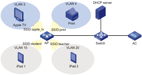
Configuration procedure
1. Configure wireless services on the AC. (Details not shown.)
2. Configure the DHCP server to assign an IP address of the AC as the gateway IP address of the clients. (Details not shown.)
3. Configure Bonjour gateway:
# Enable Bonjour gateway globally.
<AC> system-view
[AC] wlan bonjour-gateway enable
# Create Bonjour policy teacher to allow clients going online through SSID teacher to query services in VLAN 3 and VLAN 4.
[AC] wlan bonjour-policy teacher
[AC-wlan-bp-teacher] service vlan 3 4
# Create Bonjour policy student to allow clients going online through SSID student to query services in VLAN 4.
<AC> system-view
[AC] wlan bonjour-policy student
[AC-wlan-bp-student] service vlan 4
# Apply Bonjour policy student to service template with SSID student.
[AC] wlan service-template 10 clear
[AC-wlan-st-10] ssid student
[AC-wlan-st-10] bonjour-policy student
[AC-wlan-st-10] service-template enable
# Apply Bonjour policy teacher to service template with SSID teacher.
[AC] wlan service-template 11 clear
[AC-wlan-st-11] ssid teacher
[AC-wlan-st-11] bonjour-policy teacher
[AC-wlan-st-11] service-template enable
Verifying the configuration
1. Use the display wlan bonjour-service command to verify that the AC can discover the services of both Apple TV and Print. (Details not shown.)
2. Use the display wlan client verbose command to verify that iPad 1 can discover only the service of Print and iPad 2 can discover the services of both Apple TV and Print. (Details not shown.)
Configuring Hotspot 2.0
Support for this feature depends on the device model. For more information, see About the H3C Access Controllers Configuration Guides.
Overview
Hotspot 2.0, developed based on 802.11u, implements automatic network discovery, automatic authentication, and seamless roaming for wireless clients.
The AC supports the following functions in Hotspot 2.0:
· Automatic network discovery—The AC and clients exchange Hotspot 2.0 capabilities by using active or passive scanning. If both of them support Hotspot 2.0, the clients can get external network information by exchanging Generic Advertisement Service (GAS) frames with the AC before being associated with an AP.
· Security—When the Downstream Group-Addressed Forwarding (DGAF) function is enabled for an AP, the AP forwards all downstream wireless broadcast ARP packets and wireless multicast packets. To prevent spoofing attacks by using downstream multicasts, you can disable the DGAF function for the AP.
· Network management—Controls frame transmission between clients and the AC.
Configuring a Hotspot 2.0 policy
Hotspot 2.0 does not take effect when local forwarding is enabled.
Configuring automatic network discovery
This feature enables clients to discover a range of information through GAS frames sent by the AC, including WAN link information, service provider information, and AP venue information.
The following configurations take effect only when the Hotspot 2.0 policy is applied to a service template.
To configure automatic network discovery:
|
Command |
Remarks |
|
|
1. Enter system view. |
system-view |
N/A |
|
2. Create a Hotspot 2.0 policy and enter Hotspot 2.0 policy view. |
wlan hotspot-policy policy-number |
N/A |
|
3. Configure 3GPP information. |
3gpp-info country-code country-code network-code network-code |
Optional. By default, no 3GPP information is configured. |
|
4. Set a domain name. |
domain-name name |
Optional. By default, no domain name is configured. |
|
5. Set an HESSID. |
hessid hessid |
Optional. By default, no HESSID is configured. |
|
6. Set IP address availability. |
ip-type ipv4 ipv4-type ipv6 ipv6-type |
Optional. By default, the availability is 1 for an IPv4 address and 2 for an IPv6 address. |
|
7. Configure service provider information. |
operator-name operator-name lang-code lang-code |
Optional. By default, no service provider information is configured. |
|
8. Set an OUI for a roaming consortium. |
roam-oui oui [ in-beacon ] |
Optional. By default, no OUI is configured for a roaming consortium. |
|
9. Set a Hotspot 2.0 policy name. |
policy-name policy-name |
Optional. By default, no Hotspot 2.0 policy name is specified. |
|
10. Configure a network authentication type. |
authentication-type authentication-type [ redirect-url url-address ] |
Optional. By default, no network authentication type is configured. |
|
11. Configure an authentication type for an NAI realm. |
nai-realm name name eap-method eap-method-id authentication authentication |
Optional. By default, no authentication type is configured for an NAI realm. |
|
12. Configure NAI realms to use the manually configured storage sequence. |
nai-realm unsorted |
Optional. By default, NAI realms use the alphabetical storage sequence. |
|
13. Configure WAN parameters. |
wan-metrics { link-down | link-test | link-up } [ asymmetric downlink-speed downlink-speed uplink-speed uplink-speed | symmetric link-speed link-speed ] |
Optional. By default, no WAN parameters are configured. |
To configure AP venue information:
|
Step |
Command |
Remarks |
|
1. Enter system view. |
system-view |
N/A |
|
2. Enter AP template view or AP group view. |
· Enter AP template view: · Enter AP group view: |
Use either method. |
|
3. Configure a venue group and venue type for the AP. |
ap-venue group venue-group type venue-type |
Optional. By default, no venue group and venue type are configured for an AP. |
|
4. Configure venue name information for the AP. |
ap-venue name venue-name lang-code lang-code |
Optional. By default, no venue name information is configured for an AP. |
Disabling the DGAF function
When the DGAF function is enabled for an AP, the AP forwards all downstream wireless broadcast ARP packets and wireless multicast packets. To prevent spoofing attacks by using downstream multicasts, you can disable the DGAF function for the AP.
As a best practice to avoid packet loss, enable proxy ARP and multicast optimization before disabling this function.
To disable the DGAF function:
|
Step |
Command |
Remarks |
|
1. Enter system view. |
system-view |
N/A |
|
2. Create a Hotspot 2.0 policy and enter Hotspot 2.0 policy view. |
wlan hotspot-policy policy-number |
N/A |
|
3. Disable the DGAF function. |
undo dgaf enable |
Optional. By default, the DGAF function is enabled. |
Configuring network management parameters
This feature controls packet transmission between clients and the AC to enhance network management.
To configure network management parameters:
|
Step |
Command |
Remarks |
|
1. Enter system view. |
system-view |
N/A |
|
2. Create a Hotspot 2.0 policy and enter Hotspot 2.0 policy view. |
wlan hotspot-policy policy-number |
N/A |
|
3. Set the delay time for the clients to send GAS comeback frames. |
comeback-delay value |
Optional. By default, the delay time is 1 TU. |
|
4. Configure the maximum number of GAS Initial frames the AC can receive from clients within the specified interval. |
gas-limit number number interval interval |
Optional. By default, the number of GAS initial frames the AC can receive is not restricted. |
Applying a Hotspot 2.0 policy
Follow these restrictions and guidelines when you apply a Hotspot 2.0 policy:
· A Hotspot 2.0 policy can only be applied to a crypto-type service template with the WPA encryption method and 802.1X authentication type.
· As a best practice, use the attack-detection enable flood command to enable flood attack detection.
To apply a Hotspot 2.0 policy:
|
Step |
Command |
Remarks |
|
1. Enter system view. |
system-view |
N/A |
|
2. Configure a crypto-type service template. |
wlan service-template service-template-number crypto |
You cannot change an existing template to another type. |
|
3. Apply a Hotspot 2.0 policy to the service template. |
hotspot-policy policy-number |
By default, no Hotspot 2.0 policy is applied to the service template. |
