- Table of Contents
-
- 02-WLAN Configuration Guide
- 00-Preface
- 01-WLAN Interface Configuration
- 02-WLAN Access Configuration
- 03-WLAN Security Configuration
- 04-IACTP Tunnel and WLAN Roaming Configuration
- 05-WLAN RRM Configuration
- 06-WLAN IDS Configuration
- 07-WLAN QoS Configuration
- 08-WLAN Mesh Link Configuration
- 09-Advanced WLAN Configuration
- 10-WLAN High Availability Configuration
- 11-WLAN IPS Configuration
- 12-WLAN Optimization Configuration
- Related Documents
-
| Title | Size | Download |
|---|---|---|
| 07-WLAN QoS Configuration | 210.01 KB |
Configuration restrictions and guidelines
Displaying and maintaining WMM
Configuring bandwidth guaranteeing
Displaying and maintaining bandwidth guaranteeing
Bandwidth guaranteeing configuration example
Configuring client rate limiting
Displaying and maintaining client rate limiting
Client rate limiting configuration example
Configuring WLAN QoS
Overview
An 802.11 network offers contention-based wireless access. To provide applications with QoS services, IEEE developed 802.11e for the 802.11-based WLAN architecture.
While IEEE 802.11e was being standardized, Wi-Fi Alliance defined the Wi-Fi Multimedia (WMM) standard to allow QoS provision devices of different vendors to interoperate. WMM makes a WLAN network capable of providing QoS services.
Terminology
· WMM—A wireless QoS protocol designed to preferentially transmit packets with high priority, thus guaranteeing better QoS services for voice and video applications in a wireless network.
· Enhanced distributed channel access (EDCA)—A channel contention mechanism designed by WMM to preferentially transmit packets with high priority and allocate more bandwidth to such packets.
· Access category (AC)—Used for channel contention. WMM defines four access categories. They are AC-VO (voice) queue, AC-VI (video) queue, AC-BE (best-effort) queue, and AC-BK (background) queue in the descending order of priority. When contending for a channel, a high-priority AC queue preempts a low-priority AC queue.
· Connection admission control (CAC)—Limits the number of clients that are using high-priority AC queues (including AC-VO and AC-VI queues) to guarantee sufficient bandwidth for existing high-priority traffic.
· Unscheduled Automatic Power-Save Delivery (U-APSD)—A new power-saving mechanism defined by WMM to enhance the power-saving capability of clients.
· SpectraLink voice priority (SVP)—A voice priority protocol designed by the SpectraLink company to guarantee QoS for voice traffic.
WMM protocol
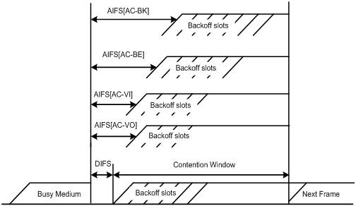
The distributed coordination function (DCF) in 802.11 stipulates that access points (APs) and clients use the carrier sense multiple access with collision avoidance (CSMA/CA) access mechanism. APs or clients listen to the channel before they hold the channel for data transmission. When the specified idle duration of the channel times out, APs or clients randomly select a backoff slot within the contention window to perform backoff. The device that finishes backoff first gets the channel. With 802.11, all devices have the same idle duration and contention window. Therefore, they are equal when contending for a channel. In WMM, this fair contention mechanism is changed.
EDCA parameters
WMM assigns data packets in a basic service set (BSS) to four AC queues. By allowing a high-priority AC queue to have more channel contention opportunities than a low-priority AC queue, WMM offers different service levels to different AC queues.
WMM defines a set of EDCA parameters for each AC queue, covering the following:
· Arbitration inter-frame spacing number (AIFSN)—Different from the 802.11 protocol where the idle duration (set using DIFS) is a constant value, WMM can define an idle duration per AC queue. The idle duration increases as the AIFSN value increases (see Figure 1 for the AIFS durations).
· Exponent form of CWmin (ECWmin) and exponent form of CWmax (ECWmax)—Determine the average backoff slots, which increases as the two values increase (see Figure 1 for the backoff slots).
· Transmission opportunity limit (TXOPLimit)—Indicates the maximum time for which a user can hold a channel after a successful contention. The greater the TXOPLimit, the longer the user can hold the channel. The value 0 indicates that the user can send only one packet each time it holds the channel.
Figure 1 Per-AC channel contention parameters in WMM
CAC admission policies
CAC requires that a client obtain permission of the AP before it can use a high-priority AC queue for transmission, guaranteeing bandwidth to the clients that have gained access. CAC controls real-time traffic (AC-VO and AC-VI traffic) but not common data traffic (AC-BE and AC-BK traffic).
If a client wants to use a high-priority AC queue, it must send a request to the AP. The AP returns a positive or negative response based on either of the following admission control policies:
· Channel utilization-based admission policy—The AP calculates the total time that the existing high-priority AC queues occupy the channel in one second, and then calculates the time that the requesting traffic will occupy the channel in one second. If the sum of the two values is smaller than or equal to the maximum hold time of the channel, the client can use the requested AC queue. Otherwise, the request is rejected.
· Users-based admission policy—If the number of clients using high-priority AC queues plus the clients requesting for high-priority AC queues is smaller than or equal to the maximum number of high-priority AC queue clients, the request is accepted. Otherwise, the request is rejected. During calculation, a client is counted once even if it is using both the AC-VO and AC-VI queues.
U-APSD power-save mechanism
U-APSD improves the 802.11 APSD power-saving mechanism. When associating clients with AC queues, you can specify some AC queues as trigger-enabled, some AC queues as delivery-enabled, and the maximum number of data packets that can be delivered after receiving a trigger packet. Both the trigger attribute and the delivery attribute can be modified when flows are established using CAC. When a client sleeps, the delivery-enabled AC queue packets destined for the client are buffered. The client must send a trigger-enabled AC queue packet to get the buffered packets. After the AP receives the trigger packet, packets in the transmit queue are sent. The number of sent packets depends on the agreement made when the client was admitted. AC queues without the delivery attribute store and transmit packets as defined in the 802.11 protocol.
SVP
SVP can assign packets with the protocol ID 119 in the IP header to a specific AC queue. SVP stipulates that random backoff is not performed for SVP packets. Therefore, you can set both ECWmin and ECWmax to 0 when there are only SVP packets in an AC queue.
ACK policy
WMM defines two ACK policies:
· No ACK—When the no acknowledgement (No ACK) policy is used, the recipient does not acknowledge received packets during wireless packet exchange. This policy is suitable in the environment where communication quality is fine and interference is weak. While the No ACK policy helps improve transmission efficiency, it can cause increased packet loss when communication quality deteriorates. This is because when this policy is used, a sender does not retransmit packets that have not been received by the recipient.
Protocols and standards
· 802.11e-2005, Amendment 8: Medium Access Control (MAC) Quality of Service Enhancements, IEEE Computer Society, 2005
· Wi-Fi, WMM Specification version 1.1, Wi-Fi Alliance, 2005
Configuring WMM
Configuration restrictions and guidelines
· If CAC is enabled for an AC queue, CAC is also enabled for the AC queues with higher priority. For example, if you use the wmm edca client command to enable CAC for the AC-VI queue, CAC is also enabled for the AC-VO queue. However, enabling CAC for the AC-VO queue does not enable CAC for the AC-VI queue.
· H3C recommends that you use the default EDCA parameter settings for APs and clients (except the TXOPLimit parameter for devices using 802.11b radio cards) unless it is necessary to modify the default settings.
· When the radio card of a device is 802.11b, H3C recommends that you set the TXOPLimit values of the AC-BK, AC-BE, AC-VI, and AC-VO queues to 0, 0, 188, and 102, respectively.
· The SVP packet mapping function takes effect only after you enable WMM.
Configuration procedure
|
Step |
Command |
Remarks |
|
1. Enter system view. |
system-view |
N/A |
|
2. Create a radio policy and enter radio policy view. |
wlan radio-policy radio-policy-name |
N/A |
|
3. Enable WMM. |
wmm enable |
By default, WMM is enabled. The 802.11n protocol stipulates that all 802.11n clients support WLAN QoS. Therefore, when the radio operates in 802.11an or 802.11gn mode, you should enable WMM. Otherwise, the associated 802.11n clients will operate in 802.11a or 802.11g mode. |
|
4. Set the EDCA parameters of AC-VO or AC-VI queues for clients. |
wmm edca client { ac-vo | ac-vi } { aifsn aifsn-value | ecw ecwmin ecwmin-value ecwmax ecwmax -value | txoplimit txoplimit-value | cac } * |
Optional. By default, a client uses the default EDCA parameters shown in Table 1. |
|
5. Set the EDCA parameters of AC-BE or AC-BK queues for clients. |
wmm edca client { ac-be | ac-bk } { aifsn aifsn-value | ecw ecwmin ecwmin-value ecwmax ecwmax -value | txoplimit txoplimit -value } * |
Optional. By default, a client uses the default EDCA parameters shown in Table 1. |
|
6. Set the EDCA parameters and specify the ACK policy for the radio. |
wmm edca radio { ac-vo | ac-vi | ac-be | ac-bk } { aifsn aifsn-value | ecw ecwmin ecwmin-value ecwmax ecwmax -value | txoplimit txoplimit -value | noack } * |
Optional. By default, an AP uses the default EDCA parameters shown in Table 2 and uses the Normal ACK policy. |
|
7. Set the CAC policy. |
wmm cac policy { channelutilization [ channelutilization-value ] | users [ users-number ] } |
Optional. By default, the users-based admission policy applies, with the maximum number of users being 20. |
|
8. Map SVP packets to a specified AC queue. |
wmm svp map-ac { ac-vi | ac-vo | ac-be | ac-bk } |
Optional. By default, the SVP packet mapping function is disabled. SVP packet mapping applies to non-WMM clients and does not take effect on WMM clients. |
Table 1 Default EDCA parameters for clients
|
AC queue |
AIFSN |
ECWmin |
ECWmax |
TXOP Limit |
|
AC-BK queue |
7 |
4 |
10 |
0 |
|
AC-BE queue |
3 |
4 |
10 |
0 |
|
AC-VI queue |
2 |
3 |
4 |
94 |
|
AC-VO queue |
2 |
2 |
3 |
47 |
Table 2 Default EDCA parameters for APs
|
AC queue |
AIFSN |
ECWmin |
ECWmax |
|
|
AC-BK queue |
7 |
4 |
10 |
0 |
|
AC-BE queue |
3 |
4 |
6 |
0 |
|
AC-VI queue |
1 |
3 |
4 |
94 |
|
AC-VO queue |
1 |
2 |
3 |
47 |
Displaying and maintaining WMM
|
Task |
Command |
Remarks |
|
Display radio or client WMM configuration information. |
display wlan wmm { radio { all | ap ap-name } | client { all | ap ap-name | mac-address mac-address } } [ | { begin | exclude | include } regular-expression ] |
Available in any view. |
|
Display client WLAN statistics. |
display wlan statistics client { all | mac-address mac-address } [ | { begin | exclude | include } regular-expression ] |
Available in any view. |
|
Display radio WLAN statistics. |
display wlan statistics radio [ ap ap-name ] [ load ] [ | { begin | exclude | include } regular-expression ] |
Available in any view. |
|
Display WLAN radio policy information. |
display wlan radio-policy [ radio-policy-name ] [ | { begin | exclude | include } regular-expression ] |
Available in any view. |
|
Clear radio WMM statistics. |
reset wlan wmm radio { all | ap ap-name } |
Available in user view. |
|
Clear client WMM statistics. |
reset wlan wmm client { all | ap ap-name | mac-address mac-address } |
Available in user view. |
WMM configuration examples
Basic WMM configuration example
1. Network requirements
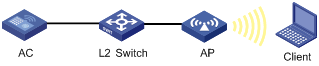
As shown in Figure 2, AP and AC are in the same network.
Enable WMM on AC, so that AP and the client can prioritize the traffic.
2. Configuration procedure
<AC> system-view
# Create interface WLAN-ESS 1, and set the link type to hybrid on the port.
[AC] interface wlan-ess 1
[AC-WLAN-ESS1] port link-type hybrid
[AC-WLAN-ESS1] quit
# Create a clear-type WLAN service template, set its SSID to market, and bind WLAN-ESS 1 to the service template.
[AC] wlan service-template 1 clear
[AC-wlan-st-1] ssid market
[AC-wlan-st-1] bind wlan-ess 1
[AC-wlan-st-1] authentication-method open-system
[AC-wlan-st-1] service-template enable
# Configure a radio policy and enable WMM. By default, WMM is enabled.
[AC] wlan radio-policy radiopolicy1
[AC-wlan-rp-radiopolicy1] wmm enable
[AC-wlan-rp-radiopolicy1] quit
# Create a template named ap1, and specify the AP model and serial ID.
[AC] wlan ap ap1 model WA3628i-AGN
[AC-wlan-ap-ap1] serial-id 210235A29G007C000020
# Bind service template 1 and radio policy radiopolicy1 to interface Radio 1.
[AC-wlan-ap-ap1] radio 1 type dot11an
[AC-wlan-ap-ap1-radio-1] radio-policy radiopolicy1
[AC-wlan-ap-ap1-radio-1] service-template 1
[AC-wlan-ap-ap1-radio-1] radio enable
After WMM is enabled, you can use the display wlan wmm radio command to view WMM-related information.
CAC service configuration example
1. Network requirements
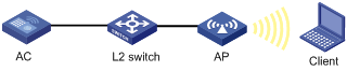
As shown in Figure 3, AP and AC are in the same network.
Configure CAC for high-priority queues (AC-VO and AC-VI queues) on the AC, and use a users-based admission policy to allow the AP to accommodate up to ten clients in the AC-VO and AC-VI queues. In this way, clients in the AC-VO and AC-VI queues can be guaranteed of enough bandwidth.
2. Configuration procedure
<AC> system-view
# Create interface WLAN-ESS 1, and set the link type to hybrid on the port.
[AC] interface WLAN-ESS 1
[AC-WLAN-ESS1] port link-type hybrid
[AC-WLAN-ESS1] quit
# Create a clear-type WLAN service template, set its SSID to market, and bind WLAN-ESS 1 to the service template.
[AC] wlan service-template 1 clear
[AC-wlan-st-1] ssid market
[AC-wlan-st-1] bind WLAN-ESS 1
[AC-wlan-st-1] authentication-method open-system
[AC-wlan-st-1] service-template enable
# Create a radio policy named radiopolicy1, enable WMM for the radio policy, enable CAC for AC-VO and AC-VI, and configure the policy to limit the number of users to 10.
[AC] wlan radio-policy radiopolicy1
[AC-wlan-rp-radiopolicy1] wmm enable
[AC-wlan-rp-radiopolicy1] wmm edca client ac-vo cac
[AC-wlan-rp-radiopolicy1] wmm edca client ac-vi cac
[AC-wlan-rp-radiopolicy1] wmm cac policy users 10
[AC-wlan-rp-radiopolicy1] quit
# Create a template named ap1, and specify the AP model and serial ID.
[AC] wlan ap ap1 model WA3628i-AGN
[AC-wlan-ap-ap1] serial-id 210235A29G007C000020
# Bind service template 1 and radio policy radiopolicy1 to interface Radio 1.
[AC-wlan-ap-ap1] radio 1 type dot11an
[AC-wlan-ap-ap1-radio-1] radio-policy radiopolicy1
[AC-wlan-ap-ap1-radio-1] service-template 1
[AC-wlan-ap-ap1-radio-1] radio enable
If a client wants to use a high-priority AC queue (AC-VO or AC-VI), it must send a request to the AP. If the number of clients using high-priority AC queues (AC-VO or AC-VI) plus the clients requesting for high-priority AC queues on AP is smaller than or equal to the maximum number of high-priority AC clients (10 in this example), the request is accepted. If the number of client exceeds the maximum number of high-priority AC clients, the system decreases the priority of the packets from the excessive clients.
SVP service configuration example
1. Network requirements
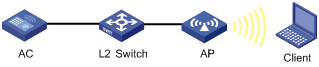
As shown in Figure 4, AP and AC are in the same network.
Configure a SVP service so SVP packets are assigned to the AC-VO queue on AP.
To guarantee the highest priority for the AC-VO queue, set ECWmin and ECWmax to 0 for the AC-VO queue of AP.

2. Configuration procedure
<AC> system-view
# Create interface WLAN-ESS 1, and set the link type to hybrid on the port.
[AC] interface WLAN-ESS 1
[AC-WLAN-ESS1] port link-type hybrid
[AC-WLAN-ESS1] quit
# Configure a clear-type WLAN service template, set its SSID to market, and bind WLAN-ESS 1 to the service template.
[AC] wlan service-template 1 clear
[AC-wlan-st-1] ssid market
[AC-wlan-st-1] bind WLAN-ESS 1
[AC-wlan-st-1] authentication-method open-system
[AC-wlan-st-1] service-template enable
# Configure radio policy radiopolicy1 and enable WMM for the radio policy.
[AC] wlan radio-policy radiopolicy1
[AC-wlan-rp-radiopolicy1] wmm enable
# Assign SVP packets to the AC-VO queue.
[AC-wlan-rp-radiopolicy1] wmm svp map-ac ac-vo
# Set both ECWmin and ECWmax to 0 for the AC-VO queue.
[AC-wlan-rp-radiopolicy1] wmm edca radio ac-vo ecw ecwmin 0 ecwmax 0
[AC-wlan-rp-radiopolicy1] quit
# Create a template named ap1, and specify the AP model and serial ID.
[AC] wlan ap ap1 model WA3628i-AGN
[AC-wlan-ap-ap1] serial-id 210235A29G007C000020
# Bind service template 1 and radio policy radiopolicy1 to interface Radio 1.
[AC-wlan-ap-ap1] radio 1 type dot11an
[AC-wlan-ap-ap1-radio-1] channel 149
[AC-wlan-ap-ap1-radio-1] radio-policy radiopolicy1
[AC-wlan-ap-ap1-radio-1] service-template 1
[AC-wlan-ap-ap1-radio-1] radio enable
If a non-WMM client comes online and sends SVP packets to the AC, the SVP packets are assigned to the AC-VO queue.
Traffic differentiation test configuration example
1. Network requirements
As shown in Figure 5, AP and AC are in the same network.
Configure the AC to map IP precedence 7 to local precedence 7, allowing such packets to occupy more bandwidth when being transmitted on the wireless network.
2. Configuration procedure
# Create a class named wmm and configure the class to match packets with an IP precedence value level of 7.
<AC> system-view
[AC] traffic classifier wmm
[AC-classifier-wmm] if-match ip-precedence 7
[AC-classifier-wmm] quit
# Create a behavior named wmm and configure the behavior to mark packets with a local precedence value of 7.
[AC] traffic behavior wmm
[AC-behavior-wmm] remark local-precedence 7
[AC-behavior-wmm] quit
# Create a policy named wmm and associate class wmm with behavior wmm in the policy.
[AC] qos policy wmm
[AC-qospolicy-wmm] classifier wmm behavior wmm
[AC-qospolicy-wmm] quit
# Apply QoS policy wmm to the incoming traffic of interface GigabitEthernet 1/0/1.
[AC] interface GigabitEthernet 1/0/1
[AC-GigabitEthernet1/0/1] qos apply policy wmm inbound
[AC-GigabitEthernet1/0/1] quit
# Create interface WLAN-ESS 1, and set the link type to hybrid on the port.
[AC] interface WLAN-ESS 1
[AC-WLAN-ESS1] port link-type hybrid
[AC-WLAN-ESS1] quit
# Enter the specified priority mapping table view. By default, the mapping table exists.
[AC] qos map-table lp-dot11e
# Create a clear-type WLAN service template, set its SSID to market, and bind WLAN-ESS 1 to the service template.
[AC] wlan service-template 1 clear
[AC-wlan-st-1] ssid market
[AC-wlan-st-1] bind WLAN-ESS 1
[AC-wlan-st-1] authentication-method open-system
[AC-wlan-st-1] service-template enable
[AC-wlan-st-1] quit
# Configure a radio policy named radiopolicy1. Then enable WMM for the policy. By default, WMM is enabled.
[AC] wlan radio-policy radiopolicy1
[AC-wlan-rp-radiopolicy1] wmm enable
[AC-wlan-rp-radiopolicy1] quit
# Create a template named ap1, and specify the AP model and serial ID.
[AC] wlan ap ap1 model WA3628i-AGN
[AC-wlan-ap-ap1] serial-id 210235A29G007C000020
# Bind service template 1 and radio policy radiopolicy1 to interface Radio 1.
[AC-wlan-ap-ap1] radio 1 type dot11an
[AC-wlan-ap-ap1-radio-1] channel 149
[AC-wlan-ap-ap1-radio-1] radio-policy radiopolicy1
[AC-wlan-ap-ap1-radio-1] service-template 1
[AC-wlan-ap-ap1-radio-1] radio enable
After the configuration, the AC maps IP precedence 7 to local precedence 7.
Troubleshooting
EDCA parameter configuration failure
Symptom
Configuring EDCA parameters for an AP failed.
Analysis
The EDCA parameter configuration of an AP is restricted by the radio chip of the AP.
Solution
1. Use the display wlan wmm radio ap ap-name command to view the support of the radio chip for the EDCA parameters. Make sure the configured EDCA parameters are supported by the radio chip.
2. Check that the values configured for the EDCA parameters are valid.
SVP or CAC configuration failure
Symptom
The SVP packet priority mapping function configured with the wmm svp map-ac command does not take effect.
CAC configured with the wmm edca client command does not take effect.
Analysis
The SVP packet priority mapping function or CAC takes effect only after WMM is enabled.
Solution
1. Use the wmm enable command to enable the WMM function.
2. Check the state of the SVP priority mapping function or CAC again.
3. The SVP packet priority mapping function takes effect on only non-WMM clients. Check whether the client is a non-WMM client.
Configuring bandwidth guaranteeing
When traffic is heavy, a BSS without any rate limitation may aggressively occupy the available bandwidth for other BSSs. If you limit the rate of the BSS, it cannot use the idle bandwidth of other BSSs.
To improve bandwidth use efficiency when ensuring bandwidth use fairness among WLAN services, use the bandwidth guaranteeing function. Bandwidth guaranteeing makes sure all traffic from each BSS can pass through freely when the network is not congested, and each BSS can get the guaranteed bandwidth when the network is congested. For example, suppose you guarantee SSID1, SSID2, and SSID3 25%, 25%, and 50% of the bandwidth. When the network is not congested, SSID1 can use all idle bandwidth in addition to its guaranteed bandwidth. When the network is congested, SSID1 can use at least its guaranteed bandwidth, 25% of the bandwidth.
This feature only applies to the traffic from AP to client.
Radios operating in 802.11ac mode do not support bandwidth guaranteeing.
Configuration procedure
To configure bandwidth guaranteeing:
|
Step |
Command |
Remarks |
|
1. Enter system view. |
system-view |
N/A |
|
2. Enter AP template view. |
wlan ap ap-name [ model model-name [ id ap-id ] ] |
N/A |
|
3. Enter radio view. |
radio radio-id |
N/A |
|
4. Enable bandwidth guaranteeing. |
bandwidth-guarantee enable |
By default, bandwidth guaranteeing is disabled. |
|
5. Set a guaranteed bandwidth percent for the specified service template. |
bandwidth-guarantee service-template service-template-number percent percent |
Optional. The service template must have been bound to the radio. For the service templates bound to the same radio, the sum of guaranteed bandwidth percents cannot exceed 100%. |
Displaying and maintaining bandwidth guaranteeing
|
Task |
Command |
Remarks |
|
Display bandwidth guaranteeing configuration. |
display wlan bandwidth-guarantee [ ap ap-name radio radio-id ] [ | { begin | exclude | include } regular-expression ] |
Available in any view. |
Bandwidth guaranteeing configuration example
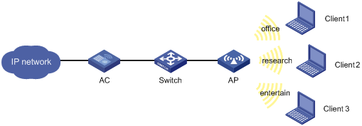
Network requirements
In an enterprise, three clients access the wireless network through WLAN services research, office, and entertain, respectively.
To make sure the enterprise network works normally, guarantee 20% of the bandwidth for WLAN service office, 80% for research, and none for entertain within the same AP.
Figure 6 Network diagram
Configuration procedure
# Set the maximum bandwidth to 10000 kbps for the 802.11a radio.
<AC> system-view
[AC] wlan rrm
[AC-wlan-rrm] dot11a max-bandwidth 10000
[AC-wlan-rrm] quit
# Create a WLAN-ESS interface.
[AC] interface wlan-ess 1
[AC-WLAN-ESS1] port link-type hybrid
[AC-WLAN-BSS1] port-security port-mode psk
[AC-WLAN-BSS1] port-security tx-key-type 11key
[AC-WLAN-BSS1] port-security preshared-key pass-phrase simple 12345678
[AC-WLAN-ESS1] quit
[AC] interface wlan-ess 2
[AC-WLAN-ESS2] port link-type hybrid
[AC-WLAN-BSS2] port-security port-mode psk
[AC-WLAN-BSS2] port-security tx-key-type 11key
[AC-WLAN-BSS2] port-security preshared-key pass-phrase simple abcdefgh
[AC-WLAN-ESS2] quit
[AC] interface wlan-ess 3
[AC-WLAN-ESS3] port link-type hybrid
[AC-WLAN-ESS3] quit
# Create service template 1 of the crypto type, and set the SSID to research for service template 1.
[AC] wlan service-template 1 crypto
[AC-wlan-st-1] ssid research
[AC-wlan-st-1] bind wlan-ess 1
[AC-wlan-st-1] authentication-method open-system
[AC-wlan-st-1] cipher-suite ccmp
[AC-wlan-st-1] security-ie rsn
[AC-wlan-st-1] service-template enable
[AC-wlan-st-1] quit
# Create service template 2 of the crypto type, and set the SSID to office for service template 2.
[AC] wlan service-template 2 crypto
[AC-wlan-st-2] ssid office
[AC-wlan-st-2] bind wlan-ess 2
[AC-wlan-st-2] authentication-method open-system
[AC-wlan-st-2] cipher-suite ccmp
[AC-wlan-st-2] security-ie rsn
[AC-wlan-st-2] service-template enable
[AC-wlan-st-2] quit
# Create service template 3 of the clear type, and set the SSID to entertain for service template 3.
[AC] wlan service-template 3 clear
[AC-wlan-st-3] ssid entertain
[AC-wlan-st-3] bind wlan-ess 3
[AC-wlan-st-3] service-template enable
[AC-wlan-st-3] quit
# Apply service templates to radio 1.
[AC] wlan ap ap1 model WA3628i-AGN
[AC-wlan-ap-ap1] serial-id 210235A29G007C000020
[AC-wlan-ap-ap1] radio 1 type dot11a
[AC-wlan-ap-ap1-radio-1] service-template 1
[AC-wlan-ap-ap1-radio-1] service-template 2
[AC-wlan-ap-ap1-radio-1] service-template 3
[AC-wlan-ap-ap1-radio-1] radio enable
# Enable bandwidth guaranteeing.
[AC-wlan-ap-ap1-radio-1] bandwidth-guarantee enable
# Set the guaranteed bandwidth percent to 80% for service template 1 and 20% for service template 2.
[AC-wlan-ap-ap1-radio-1] bandwidth-guarantee service-template 1 percent 80
[AC-wlan-ap-ap1-radio-1] bandwidth-guarantee service-template 2 percent 20
[AC-wlan-ap-ap1-radio-1] return
Verifying the configuration
# Use the display wlan bandwidth-guarantee command to display the bandwidth guaranteeing configuration.
<AC> display wlan bandwidth-guarantee
Bandwidth Guarantee
ST: service template
--------------------------------------------------------------------------------
AP Radio Mode ST Percent
--------------------------------------------------------------------------------
ap1 1 802.11a 1 80%
ap1 1 802.11a 2 20%
--------------------------------------------------------------------------------
1. When the total traffic rate from the AP to all clients is lower than 10000 kbps, the rate of traffic from the AP to any client is not limited.
2. Suppose the rate of traffic from the AP to Client 1 exceeds 2000 kbps, the rate of traffic from the AP to Client 2 exceeds 8000 kbps, and the rate of traffic from the AP to all clients exceeds 10000 kbps. In this case, because WLAN services research and office are configured with bandwidth guaranteeing, the AP will preferentially forward traffic from the AP to Client 1 and Client 2. As a result, the AP sends traffic to Client 1 at a rate of 2000 kbps, the AP sends traffic to client 2 at a rate of 8000 kbps, and the rate of traffic from the AP to Client 3 is limited.
Configuring client rate limiting
The WLAN provides limited bandwidth for each AP. Because the bandwidth is shared by wireless clients attached to the AP, aggressive use of bandwidth by a client will affect other clients. To ensure fair use of bandwidth, rate limit traffic of clients in either of the following approaches:
· Configure the total bandwidth shared by all clients. This is called "dynamic mode." The rate limit of a client is the configured total rate/the number of online clients. For example, if the configure total rate is 10 Mbps and five clients are online, the rate limit of each client is 2 Mbps.
· Configure the maximum bandwidth that can be used by each client. This is called "static mode." For example, if the configured rate is 1 Mbps, the rate limit of each client online is 1 Mbps. When the set rate limit multiplied by the number of access clients exceeds the available bandwidth provided by the AP, no clients can get the guaranteed bandwidth.
Configuration procedure
You can configure WLAN service-based client rate limiting, so that the AC can limit client rates for a WLAN service.
To configure WLAN service-based client rate limiting:
|
Step |
Command |
Remarks |
|
1. Enter system view. |
system-view |
N/A |
|
2. Enter service template view. |
wlan service-template service-template-number { clear | crypto } |
N/A |
|
3. Configure WLAN service-based client rate limiting. |
client-rate-limit direction { inbound | outbound } mode { dynamic | static } cir cir |
By default, WLAN service-based client rate limiting is disabled. |
You can configure radio-based client rate limiting, so that the AC can limit client rates for the same radio.
To configure radio-based client rate limiting:
|
Step |
Command |
Remarks |
|
1. Enter system view. |
system-view |
N/A |
|
2. Enter AP template view. |
wlan ap ap-name [ model model-name [ id ap-id ] ] |
N/A |
|
3. Enter radio view. |
radio radio-number [ type { dot11a | dot11an | dot11b | dot11g | dot11gn } ] |
N/A |
|
4. Configure radio-based client rate limiting. |
client-rate-limit direction { inbound | outbound } mode { dynamic | static } cir cir |
By default, radio-based client rate limiting is disabled. |
Displaying and maintaining client rate limiting
|
Task |
Command |
Remarks |
|
Display client rate limiting information. |
display wlan client-rate-limit { service-template [ service-template-number ] | ap [ ap-name radio radio-id ] } [ | { begin | exclude | include } regular-expression ] |
Available in any view. |
Client rate limiting configuration example
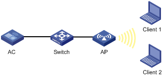
Network requirements
AC is connected to Switch, and is in the same network as the AP. Configure client rate limiting on AC, so that AP limits the incoming traffic in static mode and limits the outgoing traffic in dynamic mode for the clients.
Figure 7 Network diagram
Configuration procedure
# Enable the WLAN service. (Optional, because the WLAN service is enabled by default.)
<AC> system-view
[AC] wlan enable
# Create a WLAN-ESS interface, and set the link type to hybrid on the port.
[AC] interface wlan-ess 1
[AC-WLAN-ESS1] port link-type hybrid
[AC-WLAN-ESS1] quit
# Create a WLAN service template of the clear type, set its SSID to service, and bind interface WLAN-ESS 1 to the service template.
[AC] wlan service-template 1 clear
[AC-wlan-st-1] ssid service
[AC-wlan-st-1] bind wlan-ess 1
[AC-wlan-st-1] authentication-method open-system
# Configure WLAN service-based client rate limiting on AC to limit the rate of traffic from clients to AP (incoming traffic) to 8000 kbps in static mode and the rate of traffic from AP to clients (outgoing traffic) to 8000 kbps in dynamic mode.
[AC-wlan-st-1] client-rate-limit direction inbound mode static cir 8000
[AC-wlan-st-1] client-rate-limit direction outbound mode dynamic cir 8000
[AC-wlan-st-1] service-template enable
[AC-wlan-st-1] quit
# Create an AP template named ap1.
[AC] wlan ap ap1 model WA3628i-AGN
[AC-wlan-ap-ap1] serial-id 210235A29G007C000020
# Configure an 802.11an radio.
[AC-wlan-ap-ap1] radio 1 type dot11an
# Bind service template 1 to radio 1.
[AC-wlan-ap-ap1-radio-1] service-template 1
[AC-wlan-ap-ap1-radio-1] radio enable
[AC-wlan-ap-ap1-radio-1] return
Verifying the configuration
# Use the display wlan client-rate-limit service-template command to display the client rate limiting configuration.
<AC> display wlan client-rate-limit service-template
Client Rate Limit
--------------------------------------------------------------------------------
Service Template Direction Mode CIR(kbps)
--------------------------------------------------------------------------------
1 Inbound Static 8000
1 Outbound Dynamic 8000
--------------------------------------------------------------------------------
1. When only Client 1 accesses the WLAN through SSID service, the available bandwidth is limited to around 8000 kbps.
2. When both Client 1 and Client 2 access the WLAN through SSID service, the bandwidth available for the traffic from either Client 1 or Client 2 to the AP is limited to around 8000 kbps, and the bandwidth available for the traffic from the AP to either Client 1 or Client 2 is limited to around 4000 kbps.
