- Table of Contents
-
- 06-Layer 3 - IP Routing Configuration Guide
- 00-Preface
- 01-IP routing basics
- 02-Static routing configuration
- 03-RIP configuration
- 04-OSPF configuration
- 05-IS-IS configuration
- 06-BGP configuration
- 07-Policy-based routing configuration
- 08-IPv6 static routing configuration
- 09-RIPng configuration
- 10-OSPFv3 configuration
- 11-IPv6 IS-IS configuration
- 12-IPv6 policy-based routing configuration
- 13-Routing policy configuration
- Related Documents
-
| Title | Size | Download |
|---|---|---|
| 02-Static routing configuration | 243.96 KB |
Configuring BFD for static routes
Displaying and maintaining static routes
Static route configuration examples
Basic static route configuration example
BFD for static routes configuration example (direct next hop)
BFD for static routes configuration example (indirect next hop)
Static route FRR configuration example
Static routes are manually configured. If a network's topology is simple, you only need to configure static routes for the network to work properly.
Static routes cannot adapt to network topology changes. If a fault or a topological change occurs in the network, the network administrator must modify the static routes manually.
Configuring a static route
Before you configure a static route, complete the following tasks:
· Configure the physical parameters for related interfaces.
· Configure the link-layer attributes for related interfaces.
· Configure the IP addresses for related interfaces.
You can associate track with a static route to monitor the reachability of the next hops. For more information about track, see High Availability Configuration Guide.
To configure a static route:
|
Step |
Command |
Remarks |
|
1. Enter system view. |
system-view |
N/A |
|
2. Configure a static route. |
·
Approach 1: ·
Approach 2: |
Use either approach. By default, no static route is configured. |
|
3. (Optional.) Configure the default preference for static routes. |
ip route-static default-preference default-preference-value |
The default setting is 60. |
|
4. (Optional.) Delete all static routes, including the default route. |
delete [ vpn-instance vpn-instance-name ] static-routes all |
To delete one static route, use the undo ip route-static command. |
Configuring BFD for static routes
|
|
IMPORTANT: Enabling BFD for a flapping route could worsen the situation. |
BFD provides a general-purpose, standard, medium-, and protocol-independent fast failure detection mechanism. It can uniformly and quickly detect the failures of the bidirectional forwarding paths between two routers for protocols, such as routing protocols and MPLS.
For more information about BFD, see High Availability Configuration Guide.
Bidirectional control mode
To use BFD bidirectional control detection between two devices, enable BFD control mode for each device's static route destined to the peer.
To configure a static route and enable BFD control mode for it, specify an output interface and a direct next hop, or specify an indirect next hop and a specific BFD packet source address for the static route.
To configure BFD control mode for a static route (direct next hop):
|
Step |
Command |
Remarks |
|
1. Enter system view. |
system-view |
N/A |
|
1. Configure BFD control mode for a static route. |
· Approach 1: · Approach 2: |
Use either approach. By default, BFD control mode for a static route is not configured. |
To configure BFD control mode for a static route (indirect next hop):
|
Step |
Command |
Remarks |
|
1. Enter system view. |
system-view |
N/A |
|
2. Configure BFD control mode for a static route. |
· Approach 1: · Approach 2: |
Use either approach. By default, BFD control mode for a static route is not configured. |
Single-hop echo mode
With BFD echo mode enabled for a static route, the output interface sends BFD echo packets to the destination device, which loops the packets back to test the link reachability.
|
|
IMPORTANT: Do not use BFD for a static route with the output interface in spoofing state. |
To configure BFD echo mode for a static route:
|
Step |
Command |
Remarks |
|
1. Enter system view. |
system-view |
N/A |
|
2. Configure the source address of echo packets. |
bfd echo-source-ip ip-address |
By default, the source address of echo packets is not configured. For more information about this command, see High Availability Command Reference. |
|
3. Configure BFD echo mode for a static route. |
· Approach 1: ·
Approach 2: |
Use either approach. By default, BFD echo mode for a static route is not configured. |
Configuring static route FRR
A link or router failure on a path can cause packet loss and even routing loop. Static route fast reroute (FRR) enables fast rerouting to minimize the impact of link or node failures.
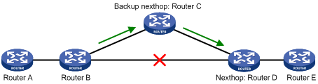
As shown in Figure 1, upon a link failure, FRR specifies a backup next hop by using a routing policy for routes matching the specified criteria. Packets are directed to the backup next hop to avoid traffic interruption.
Configuration guidelines
· Do not use static route FRR and BFD (for a static route) at the same time.
· Static route does not take effect when the backup output interface is unavailable.
· Equal-cost routes do not support static route FRR.
· The backup output interface and next hop cannot be modified directly or the same as the primary output interface and next hop.
Configuration procedure
To configure static route FRR:
|
Step |
Command |
Remarks |
|
1. Enter system view. |
system-view |
N/A |
|
2. Configure the source address of BFD echo packets. |
bfd echo-source-ip ip-address |
By default, the source address of BFD echo packets is not configured. For more information about this command, see High Availability Command Reference. |
|
3. Configure static route FRR. |
·
Approach 1: ·
Approach 2: |
Use either approach. By default, static route FRR is not configured. |
Displaying and maintaining static routes
Execute the display command in any view.
|
Task |
Command |
|
Display static route information. |
display ip routing-table protocol static [ inactive | verbose ] |
Static route configuration examples
By default, Ethernet, VLAN, and aggregate interfaces are down. To configure such an interface, bring the interface up by executing the undo shutdown command.
Basic static route configuration example
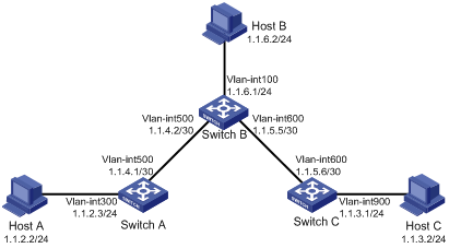
Network requirements
Configure static routes on the switches in Figure 2 for interconnections between any two hosts.
Configuration procedure
1. Configure IP addresses for interfaces. (Details not shown.)
2. Configure static routes:
# Configure a default route on Switch A.
<SwitchA> system-view
[SwitchA] ip route-static 0.0.0.0 0.0.0.0 1.1.4.2
# Configure two static routes on Switch B.
<SwitchB> system-view
[SwitchB] ip route-static 1.1.2.0 255.255.255.0 1.1.4.1
[SwitchB] ip route-static 1.1.3.0 255.255.255.0 1.1.5.6
# Configure a default route on Switch C.
<SwitchC> system-view
[SwitchC] ip route-static 0.0.0.0 0.0.0.0 1.1.5.5
Verifying the configuration
# Display static routes on Switch A.
[SwitchA] display ip routing-table protocol static
Summary Count : 1
Static Routing table Status : <Active>
Summary Count : 1
Destination/Mask Proto Pre Cost NextHop Interface
0.0.0.0/0 Static 60 0 1.1.4.2 Vlan500
Static Routing table Status : <Inactive>
Summary Count : 0
# Display static routes on Switch B.
[SwitchB] display ip routing-table protocol static
Summary Count : 2
Static Routing table Status : <Active>
Summary Count : 2
Destination/Mask Proto Pre Cost NextHop Interface
1.1.2.0/24 Static 60 0 1.1.4.1 Vlan500
Static Routing table Status : <Inactive>
Summary Count : 0
# Use the ping command on Host B to test the reachability of Host A (Windows XP runs on the two hosts).
C:\Documents and Settings\Administrator>ping 1.1.2.2
Pinging 1.1.2.2 with 32 bytes of data:
Reply from 1.1.2.2: bytes=32 time=1ms TTL=126
Reply from 1.1.2.2: bytes=32 time=1ms TTL=126
Reply from 1.1.2.2: bytes=32 time=1ms TTL=126
Reply from 1.1.2.2: bytes=32 time=1ms TTL=126
Ping statistics for 1.1.2.2:
Packets: Sent = 4, Received = 4, Lost = 0 (0% loss),
Approximate round trip times in milli-seconds:
Minimum = 1ms, Maximum = 1ms, Average = 1ms
# Use the tracert command on Host B to test the reachability of Host A.
C:\Documents and Settings\Administrator>tracert 1.1.2.2
Tracing route to 1.1.2.2 over a maximum of 30 hops
1 <1 ms <1 ms <1 ms 1.1.6.1
2 <1 ms <1 ms <1 ms 1.1.4.1
3 1 ms <1 ms <1 ms 1.1.2.2
Trace complete.
BFD for static routes configuration example (direct next hop)
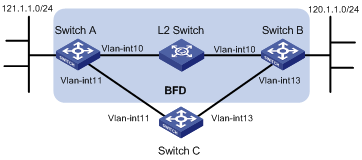
Network requirements
In Figure 3, configure a static route to subnet 120.1.1.0/24 on Switch A, and configure a static route to subnet 121.1.1.0/24 on Switch B. Enable BFD for both routes. Configure a static route to subnet 120.1.1.0/24 and a static route to subnet 121.1.1.0/24 on Switch C. When the link between Switch A and Switch B through the Layer 2 switch fails, BFD can detect the failure immediately and inform Switch A and Switch B to communicate through Switch C.
Figure 3 Network diagram
|
Device |
Interface |
IP address |
Device |
Interface |
IP address |
|
Switch A |
Vlan-int10 |
12.1.1.1/24 |
Switch B |
Vlan-int10 |
12.1.1.2/24 |
|
|
Vlan-int11 |
10.1.1.102/24 |
|
Vlan-int13 |
13.1.1.1/24 |
|
Switch C |
Vlan-int11 |
10.1.1.100/24 |
|
|
|
|
|
Vlan-int13 |
13.1.1.2/24 |
|
|
|
Configuration procedure
1. Configure IP addresses for the interfaces. (Details not shown.)
2. Configure static routes and BFD:
# Configure static routes on Switch A and enable BFD control mode for the static route that traverses the Layer 2 switch.
<SwitchA> system-view
[SwitchA] interface vlan-interface 10
[SwitchA-vlan-interface10] bfd min-transmit-interval 500
[SwitchA-vlan-interface10] bfd min-receive-interval 500
[SwitchA-vlan-interface10] bfd detect-multiplier 9
[SwitchA-vlan-interface10] quit
[SwitchA] ip route-static 120.1.1.0 24 vlan-interface 10 12.1.1.2 bfd control-packet
[SwitchA] ip route-static 120.1.1.0 24 vlan-interface 11 10.1.1.100 preference 65
[SwitchA] quit
# Configure static routes on Switch B and enable BFD control mode for the static route that traverses the Layer 2 switch.
<SwitchB> system-view
[SwitchB] interface vlan-interface 10
[SwitchB-vlan-interface10] bfd min-transmit-interval 500
[SwitchB-vlan-interface10] bfd min-receive-interval 500
[SwitchB-vlan-interface10] bfd detect-multiplier 9
[SwitchB-vlan-interface10] quit
[SwitchB] ip route-static 121.1.1.0 24 vlan-interface 10 12.1.1.1 bfd control-packet
[SwitchB] ip route-static 121.1.1.0 24 vlan-interface 13 13.1.1.2 preference 65
[SwitchB] quit
# Configure static routes on Switch C.
<SwitchC> system-view
[SwitchC] ip route-static 120.1.1.0 24 13.1.1.1
[SwitchC] ip route-static 121.1.1.0 24 10.1.1.102
Verifying the configuration
# Display BFD sessions on Switch A.
<SwitchA> display bfd session
Total Session Num: 1 Up Session Num: 1 Init Mode: Active
IPv4 Session Working Under Ctrl Mode:
LD/RD SourceAddr DestAddr State Holdtime Interface
4/7 12.1.1.1 12.1.1.2 Up 2000ms Vlan10
The output shows that the BFD session has been created.
# Display the static routes on Switch A.
<SwitchA> display ip routing-table protocol static
Summary Count : 1
Static Routing table Status : <Active>
Summary Count : 1
Destination/Mask Proto Pre Cost NextHop Interface
120.1.1.0/24 Static 60 0 12.1.1.2 Vlan10
Static Routing table Status : <Inactive>
Summary Count : 0
The output shows that Switch A communicates with Switch B through VLAN-interface 10. Then the link over VLAN-interface 10 fails.
# Display static routes on Switch A.
<SwitchA> display ip routing-table protocol static
Summary Count : 1
Static Routing table Status : <Active>
Summary Count : 1
Destination/Mask Proto Pre Cost NextHop Interface
120.1.1.0/24 Static 65 0 10.1.1.100 Vlan11
Static Routing table Status : <Inactive>
Summary Count : 0
The output shows that Switch A communicates with Switch B through VLAN-interface 11.
BFD for static routes configuration example (indirect next hop)
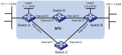
Network requirements
In Figure 4, Switch A has a route to interface Loopback 1 (2.2.2.9/32) on Switch B, with the output interface VLAN-interface 10. Switch B has a route to interface Loopback 1 (1.1.1.9/32) on Switch A, with the output interface VLAN-interface 12. Switch D has a route to 1.1.1.9/32, with the output interface VLAN-interface 10, and a route to 2.2.2.9/32, with the output interface VLAN-interface 12.
Configure a static route to subnet 120.1.1.0/24 on Switch A, and configure a static route to subnet 121.1.1.0/24 on Switch B. Enable BFD for both routes. Configure a static route to subnet 120.1.1.0/24 and a static route to subnet 121.1.1.0/24 on both Switch C and Switch D. When the link between Switch A and Switch B through Switch D fails, BFD can detect the failure immediately and inform Switch A and Switch B to communicate through Switch C.
Configuration procedure
1. Configure IP addresses for interfaces. (Details not shown.)
2. Configure static routes and BFD:
# Configure static routes on Switch A and enable BFD control mode for the static route that traverses Switch D.
<SwitchA> system-view
[SwitchA] bfd multi-hop min-transmit-interval 500
[SwitchA] bfd multi-hop min-receive-interval 500
[SwitchA] bfd multi-hop detect-multiplier 9
[SwitchA] ip route-static 120.1.1.0 24 2.2.2.9 bfd control-packet bfd-source 1.1.1.9
[SwitchA] ip route-static 120.1.1.0 24 vlan-interface 11 10.1.1.100 preference 65
[SwitchA] quit
# Configure static routes on Switch B and enable BFD control mode for the static route that traverses Switch D.
<SwitchB> system-view
[SwitchB] bfd multi-hop min-transmit-interval 500
[SwitchB] bfd multi-hop min-receive-interval 500
[SwitchB] bfd multi-hop detect-multiplier 9
[SwitchB] ip route-static 121.1.1.0 24 1.1.1.9 bfd control-packet bfd-source 2.2.2.9
[SwitchB] ip route-static 121.1.1.0 24 vlan-interface 13 13.1.1.2 preference 65
[SwitchB] quit
# Configure static routes on Switch C.
<SwitchC> system-view
[SwitchC] ip route-static 120.1.1.0 24 13.1.1.1
[SwitchC] ip route-static 121.1.1.0 24 10.1.1.102
# Configure static routes on Switch D.
<SwitchD> system-view
[SwitchD] ip route-static 120.1.1.0 24 11.1.1.1
[SwitchD] ip route-static 121.1.1.0 24 12.1.1.1
Verifying the configuration
# Display BFD sessions on Switch A.
<SwitchA> display bfd session
Total Session Num: 1 Up Session Num: 1 Init Mode: Active
IPv4 Session Working Under Ctrl Mode:
LD/RD SourceAddr DestAddr State Holdtime Interface
4/7 1.1.1.9 2.2.2.9 Up 2000ms Loop1
The output shows that the BFD session has been created.
# Display the static routes on Switch A.
<SwitchA> display ip routing-table protocol static
Summary Count : 1
Static Routing table Status : <Active>
Summary Count : 1
Destination/Mask Proto Pre Cost NextHop Interface
120.1.1.0/24 Static 60 0 12.1.1.2 Vlan10
Static Routing table Status : <Inactive>
Summary Count : 0
The output shows that Switch A communicates with Switch B through VLAN-interface 10. Then the link over VLAN-interface 10 fails.
# Display static routes on Switch A.
<SwitchA> display ip routing-table protocol static
Summary Count : 1
Static Routing table Status : <Active>
Summary Count : 1
Destination/Mask Proto Pre Cost NextHop Interface
120.1.1.0/24 Static 65 0 10.1.1.100 Vlan11
Static Routing table Status : <Inactive>
Summary Count : 0
The output shows that Switch A communicates with Switch B through VLAN-interface 11.
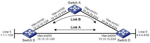
Static route FRR configuration example
Network requirements
As shown in Figure 5, configure static routes on Switch S, Switch A, and Switch D, and configure static route FRR so when Link A fails, traffic can be switched to Link B immediately.
Configuration procedure
1. Configure IP addresses for interfaces. (Details not shown.)
2. Configure static routes FRR on link A:
# Configure a static route on Switch S, and specify VLAN-inteface 100 as the backup output interface and 12.12.12.2 as the backup next hop.
<SwitchS> system-view
[SwitchS] bfd echo-source-ip 4.4.4.4
[SwitchS] ip route-static 4.4.4.4 32 vlan-interface 200 13.13.13.2 backup-interface vlan-interface 100 backup-nexthop 12.12.12.2
# Configure a static route on Switch D, and specify VLAN-interface 101 as the backup output interface and 24.24.24.2 as the backup next hop.
<SwitchD> system-view
[SwitchD] bfd echo-source-ip 1.1.1.1
[SwitchD] ip route-static 1.1.1.1 32 vlan-interface 200 13.13.13.1 backup-interface vlan-interface 101 backup-nexthop 24.24.24.2
3. Configure static routes on Switch A.
<SwitchA> system-view
[SwitchA] ip route-static 4.4.4.4 32 vlan-interface 101 24.24.24.4
[SwitchA] ip route-static 1.1.1.1 32 vlan-interface 100 12.12.12.1
Verifying the configuration
# Display route 4.4.4.4/32 on Switch S to view the backup next hop information.
[SwitchS] display ip routing-table 4.4.4.4 verbose
Summary Count : 1
Destination: 4.4.4.4/32
Protocol: Static Process ID: 0
SubProtID: 0x0 Age: 04h20m37s
Cost: 0 Preference: 60
Tag: 0 State: Active Adv
OrigTblID: 0x0 OrigVrf: default-vrf
TableID: 0x2 OrigAs: 0
NBRID: 0x26000002 LastAs: 0
AttrID: 0xffffffff Neighbor: 0.0.0.0
Flags: 0x1008c OrigNextHop: 13.13.13.2
Label: NULL RealNextHop: 13.13.13.2
BkLabel: NULL BkNextHop: 12.12.12.2
Tunnel ID: Invalid Interface: Vlan-interface200
BkTunnel ID: Invalid BkInterface: Vlan-interface100
# Display route 1.1.1.1/32 on Switch D to view the backup next hop information.
[SwitchD] display ip routing-table 1.1.1.1 verbose
Summary Count : 1
Destination: 1.1.1.1/32
Protocol: Static Process ID: 0
SubProtID: 0x0 Age: 04h20m37s
Cost: 0 Preference: 60
Tag: 0 State: Active Adv
OrigTblID: 0x0 OrigVrf: default-vrf
TableID: 0x2 OrigAs: 0
NBRID: 0x26000002 LastAs: 0
AttrID: 0xffffffff Neighbor: 0.0.0.0
Flags: 0x1008c OrigNextHop: 13.13.13.1
Label: NULL RealNextHop: 13.13.13.1
BkLabel: NULL BkNextHop: 24.24.24.2
Tunnel ID: Invalid Interface: Vlan-interface200
BkTunnel ID: Invalid BkInterface: Vlan-interface101
A default route is used to forward packets that do not match any specific routing entry in the routing table. Without a default route, packets that do not match any routing entries are discarded and an ICMP destination-unreachable packet is sent to the source.
A default route can be configured in either of the following ways:
· The network administrator can configure a default route with both destination and mask being 0.0.0.0. For more information, see "Configuring a static route."
· Some dynamic routing protocols, such as OSPF, RIP, and IS-IS, can generate a default route. For example, an upstream router running OSPF can generate a default route and advertise it to other routers, which install the default route with the next hop being the upstream router. For more information, see the respective chapters on these routing protocols in this configuration guide.
