- Table of Contents
-
- H3C S9500 Operation Manual-Release1648[v1.24]-01 Access Volume
- 00-1Cover
- 01-Ethernet Port Configuration
- 02-POS Port Configuration
- 03-Link Aggregation Configuration
- 04-Port Isolation Configuration
- 05-VLAN Configuration
- 06-MAC Address Table Management Configuration
- 07-GVRP Configuration
- 08-QinQ Configuration
- 09-Ethernet Port Loopback Detection Configuration
- 10-DLDP Configuration
- 11-Ethernet OAM Configuration
- 12-Smart Link and Monitor Link Configuration
- 13-MSTP Configuration
- 14-BPDU Tunnel Configuration
- 15-HVRP Configuration
- 16-RRPP Configuration
- 17-RPR Configuration
- Related Documents
-
| Title | Size | Download |
|---|---|---|
| 10-DLDP Configuration | 76.01 KB |
1.1.2 Notes on DLDP Configuration
1.2.1 Basic DLDP Configuration Tasks.
1.2.2 Resetting DLDP Configuration
1.3 DLDP Configuration Example
Chapter 1 DLDP Configuration
When configuring DLDP, go to these sections for information that you are interested in:
1.1 Introduction to DLDP
Sometimes, unidirectional links may appear in networks. On a unidirectional link, one end can receive packets from the other end but the other end cannot. Unidirectional links result in problems such as loops in a spanning tree.
As for fiber links, two kinds of unidirectional links exist. One occurs when fibers are cross-connected, as shown in Figure 1-1. The other occurs when one end of a fiber is not connected or one fiber of a fiber pair gets disconnected, as illustrated by the hollow arrows in Figure 1-2.

Figure 1-1 Unidirectional fiber link: cross-connected fibers
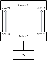
Figure 1-2 Unidirectional fiber link: fiber not connected or disconnected
As a data link layer protocol, DLDP cooperates with physical layer protocols to monitor the link status of a device. While the auto-negotiation mechanism provided by the physical layer detects physical signals and faults, DLDP performs operations such as identifying peer devices, detecting unidirectional links, and shutting down unreachable ports.
The cooperation of the physical layer and DLDP ensures that physical/logical unidirectional links be detected and shut down, thus preventing protocols such as STP from becoming ineffective.
If the two sides of a link operate properly at the physical layer, DLDP checks whether the link is correctly connected and packets are exchanged properly at the data link layer. Such detection is impossible with the auto-negotiation mechanism of the physical layer.
Ports shut down by DLDP due to unidirectional links detected can be brought up automatically if the links restore to bidirectional links.
& Note:
Do not configure a DLDP-enabled port as a loopback port.
1.1.1 DLDP Fundamentals
I. DLDP states
A device can operate in these DLDP states: initial, inactive, active, advertisement, probe, and disable.
|
State |
Indicates… |
|
Initial |
DLDP is disabled. |
|
Inactive |
DLDP is enabled but the link is down. |
|
Active |
DLDP is enabled and the link is up, or the neighbor entries have been cleared. |
|
Advertisement |
All neighbors are bi-directionally reachable or DLDP has been in active state for more than five seconds. This is a relative state where no bidirectional link has been detected. |
|
Probe |
DLDP is probing for a unidirectional link. As soon as DLDP transits to this state, a probe timer starts and an Echo timeout timer starts for each neighbor to be probed. |
|
Disable |
DLDP has detected a unidirectional link or the contact with the neighbor in enhanced mode has been lost. |
II. Timers used in DLDP
Table 1-2 lists the timers used in DLDP.
|
Timer |
Description |
|
Advertisement timer |
This timer sets the interval for advertisement. You can set the interval at the command line interface (CLI). The default interval for advertisement is 5 seconds. |
|
Probe timer |
The probe timer is set to one second. DLDP in the probe state sends two probe packets per second. |
|
Echo timer |
This timer starts when DLDP transits to the probe state. It is set to 10 seconds. DLDP transits to the disable state if no response echo packet has been received from one of its neighbors before the echo timer times out. The DLDP process then generates the log and debugging information, sends disable packets, and shuts down the port automatically or asks the user to do so as configured. The corresponding entry is removed as well. |
|
Entry aging timer |
A neighbor entry is created when a new neighbor is added; at the same time, an aging timer starts for the entry. When the device receives packets from its neighbors, the corresponding neighbor entries and entry aging timers are refreshed In the normal mode, the device sends advertisement packets with the RSY tag (a tag requesting packet synchronization). If no response has been received from a neighbor upon timeout of the entry aging timer, the corresponding neighbor entry will be removed. When the device is operating in the enhanced mode, an enhanced timer starts if the device has not received any packet from a neighbor when the entry aging timer times out. The entry aging timer is set to a value that is three times that of the advertisement timer. |
|
Enhanced timer |
l An enhanced timer starts for a neighbor if no packet has been received from the neighbor before the entry aging timer times out. The enhanced timer is set to 10 seconds. l After the enhanced timer starts, DLDP sends eight probe packets to the neighbor at the rate of two packets per second. DLDP sets the local end state to unidirectional and transits to the disable state if no response echo has been received from any of its neighbors before the enhanced timer times out. DLDP process then generates the log and debugging information, sends disable packets, and shuts down the port automatically or asks the user to do so as configured. The corresponding entry is removed as well. |
|
Recover probe timer |
The recover probe timer is two seconds. A DLDP port in disable state sends a RecoverProbe packet every two seconds to check whether the unidirectional link has been repaired. |
III. DLDP operation modes
Two DLDP operation modes exist: normal mode and enhanced mode, as described in Table 1-3.
Table 1-3 DLDP operation modes and neighbor entry aging
|
DLDP operation mode |
Whether to check the existence of a neighbor when the corresponding neighbor entry ages out |
Starts an entry aging timer to age a neighbor entry |
Starts the enhanced timer when the entry aging timer times out |
|
Normal mode |
No |
Yes |
No (A neighbor entry is aged when the entry aging timer times out.) |
|
Enhanced mode |
Yes |
Yes |
Yes (When the enhanced timer times out, the local side changes to operate in the disable state, and the neighbor entry is aged.) |
IV. DLDP work flow
1) When the link state of a DLDP-enabled port is up, DLDP sends DLDP packets to the peer and processes the DLDP packets received from the peer. Table 1-4 lists the packets that DLDP uses in different states.
|
DLDP state |
DLDP packet |
|
Active |
Advertisement packets (with the RSY tag) |
|
Advertisement |
Advertisement packets |
|
Probe |
Probe packets |
|
Disable |
RecoverProbe packets |
2) A received DLDP packet is processed as follows:
l In authentication mode, the DLDP packet is authenticated and is then dropped if it fails the authentication.
l In non-authentication mode, the DLDP packet is processed depending on its type, as shown in Table 1-5.
Table 1-5 Actions performed upon receipt of a DLDP packet
|
Packet type |
Action |
|||||
|
Advertisement |
Extract the neighbor information from the packet. |
If the corresponding neighbor entry does not exist, DLDP creates the neighbor entry, starts the entry aging timer, and transits to the probe state. |
||||
|
If the corresponding neighbor entry already exists on the local device, DLDP resets the aging timer of the entry. |
||||||
|
Flush |
Remove the neighbor entry. |
|||||
|
Probe |
Respond with an echo packet containing the information about the neighbor and itself |
Create the neighbor entry if it does not exist. |
||||
|
Reset the aging timer of the entry if the neighbor entry already exists. |
||||||
|
Echo |
Check whether the local device is in the probe state |
No |
Drop the echo packet. |
|||
|
Yes |
Check whether the received neighbor information is the same as that retained on the local device |
No |
Drop the echo packet. |
|||
|
Yes |
Set the neighbor state to two way, that is, bidirectional link state. |
|||||
|
If all neighbors are in the bidirectional link state, DLDP transits from the probe state to the advertisement state, and sets the echo waiting timer to 0. |
||||||
|
Disable |
Transit to the disable state |
|||||
|
Linkdown |
Check whether DLDP is operating in the enhanced mode |
No |
Drop the packet |
|||
|
Yes |
Transit to the disable state |
|||||
|
RecoverProbe |
Check whether the local device is operating in the disable state or the advertisement state |
No |
Drop the packet |
|||
|
Yes |
Send a RecoverEcho packet |
|||||
|
RecoverEcho |
Check whether the local device is operating in the disable state |
No |
Drop the packet |
|||
|
Yes |
Check whether the neighbor information carried in the RecoverEcho packet is consistent with that retained on the local device |
No |
Drop the packet |
|||
|
Yes |
Reset the DLDP state of the port |
|||||
3) If no echo packet is received from the neighbor, DLDP does the following:
Table 1-6 Operations performed when no echo packet is received
|
Condition |
Processing procedure |
|
In normal mode, no echo packet has been received when the echo waiting timer expires |
DLDP transits to the disable state, outputs log and tracking information, and sends flush packets. Depending on the user-defined DLDP down mode, DLDP shuts down the local port automatically or asks you to do so. DLDP sends RSY messages and removes the corresponding neighbor entries. |
|
In enhanced mode, no echo packet has been received when the enhanced timer expires |
1.1.2 Notes on DLDP Configuration
l DLDP takes effect only when a link is present.
l To ensure unidirectional links can be detected, make sure DLDP is enabled on both sides; and the interval for sending advertisement packets, authentication mode, and password are the same on both sides.
l The interval for DLDP advertisement is tunable allowing DLDP to respond in time to link failures in different network environments. If the interval is too long, STP loops may occur before unidirectional links are terminated; if the interval is too short, undesired network traffic may increase to consume available bandwidth. Normally, the interval should be shorter than one-third of the STP convergence time.
l DLDP does not process any LACP event. It treats every link in a link aggregation group as distinct.
l DLDP is only available on Ethernet ports.
l The LSB1XP4CA0 board does not support DLDP.
1.2 DLDP Configuration
1.2.1 Basic DLDP Configuration Tasks
Follow these steps to configure DLDP:
|
To do … |
Use the command … |
Remarks |
|
Enter system view |
system-view |
— |
|
Enter port view |
interface interface-type interface-number |
— |
|
Enable DLDP |
dldp enable |
Required Disabled by default |
|
Configure the authentication mode and the password |
dldp authentication-mode { none | simple password | md5 password } |
Optional By default, authentication is not performed. |
|
Set the interval for sending DLDP packets |
dldp interval integer |
Optional The default is 5 seconds. |
|
Configure the operation to be performed when a unidirectional link is detected |
dldp unidirectional-shutdown { auto | manual } |
Optional By default, the auto keyword is specified. |
|
Configure the DLDP operation mode |
dldp work-mode { enhance | normal } |
Optional By default, the normal DLDP operation mode is adopted. |
|
Display the configurations of the ports with DLDP enabled |
display dldp [ interface-type interface-number ] |
Available in any view. |
![]() Caution:
Caution:
DLDP takes effect only when the local port and the peer port are configured with the same authentication mode and password.
1.2.2 Resetting DLDP Configuration
& Note:
l You can reset the DLDP state for the ports shut down by DLDP due to unidirectional links to enable DLDP detection again.
l When you use the display interface command to view the state of a port shut down by DLDP, the port state is displayed as DLDP DOWN. However, the indicator of the port is on.
Follow these steps to reset the DLDP state:
|
To do … |
Use the command … |
Remarks |
||
|
Reset DLDP configuration |
Enter system view |
system-view |
Optional |
|
|
Reset DLDP configuration globally |
dldp reset |
|||
|
Reset DLDP configuration for a port |
Enter Ethernet port view |
interface interface-type interface-number |
||
|
Reset DLDP configuration for the fast Ethernet port |
[H3C-EthernetX/1/X] dldp reset |
|||
|
Reset DLDP configuration for the GigabitEthernet port |
[H3C-GigabitEthernetX/1/X] dldp reset |
|||
![]() Caution:
Caution:
Resetting DLDP is applicable to the ports that are in DLDP down state only.
1.3 DLDP Configuration Example
I. Network requirements
The two DLDP-capable switches are connected through two pairs of optical fibers.
Configure DLDP on the switches to meet the following requirements:
l When DLDP detects a unidirectional link, DLDP disconnects the unidirectional link automatically.
l The ports shut down by DLDP can be brought up after the optical fibers are correctly connected.
II. Network diagram

Figure 1-3 Network diagram for DLDP configuration
III. Configuration procedure
1) Configure Switch A
# Configure the ports to operate in forced full duplex mode.
<SwitchA> system-view
[SwitchA] interface gigabitethernet 2/1/3
[SwitchA-GigabitEthernet2/1/3] duplex full
[SwitchA-GigabitEthernet2/1/3] speed 1000
[SwitchA-GigabitEthernet2/1/3] quit
[SwitchA] interface gigabitethernet 2/1/4
[SwitchA-GigabitEthernet2/1/4] duplex full
[SwitchA-GigabitEthernet2/1/4] speed 1000
[SwitchA-GigabitEthernet2/1/4] quit
# Enable DLDP on GigabitEthernet 2/1/3 and GigabitEthernet 2/1/4.
[SwitchA] interface gigabitethernet 2/1/3
[SwitchA-GigabitEthernet2/1/3] dldp enable
[SwitchA-GigabitEthernet2/1/3] quit
[SwitchA] interface gigabitethernet 2/1/4
[SwitchA-GigabitEthernet2/1/4] dldp enable
# Set the interval for sending DLDP packets to 15 seconds.
[SwitchA-GigabitEthernet2/1/4] quit
[SwitchA] dldp interval 15
# Configure the switch to operate in enhanced DLDP mode.
[SwitchA] dldp work-mode enhance
# Set the action upon detection of a unidirectional link to auto, allowing the system to automatically shut down the port.
[SwitchA] dldp unidirectional-shutdown auto
2) Configure Switch B
# Configure the ports to operate in forced full duplex mode.
<SwitchB> system-view
[SwitchB] interface gigabitethernet 2/1/3
[SwitchB-GigabitEthernet2/1/3] duplex full
[SwitchB-GigabitEthernet2/1/3] speed 1000
[SwitchB-GigabitEthernet2/1/3] quit
[SwitchB] interface gigabitethernet 2/1/4
[SwitchB-GigabitEthernet2/1/4] duplex full
[SwitchB-GigabitEthernet2/1/4] speed 1000
[SwitchB-GigabitEthernet2/1/4] quit
# Enable DLDP on GigabitEthernet 2/1/3 and GigabitEthernet 2/1/4.
[SwitchB] interface gigabitethernet 2/1/3
[SwitchB-GigabitEthernet2/1/3] dldp enable
[SwitchB-GigabitEthernet2/1/3] quit
[SwitchB] interface gigabitethernet 2/1/4
[SwitchB-GigabitEthernet2/1/4] dldp enable
# Set the interval for sending DLDP packets to 15 seconds.
[SwitchB-GigabitEthernet2/1/4] quit
[SwitchB] dldp interval 15
# Configure the switch to operate in the enhanced DLDP mode.
[SwitchB] dldp work-mode enhance
# Configure the unidirectional operation mode to be auto.
[SwitchB] dldp unidirectional-shutdown auto
# Display DLDP information about Switch B.
[SwitchB] display dldp
If the switches are correctly connected, the output information should indicate that the links between the switch and its neighbors are bi-directionally reachable (two way links). Otherwise, the output information will indicate that the links are unidirectional (one way links).
& Note:
To detect the links with one optical fiber not connected at one end, make sure the ports are operating in the forced full duplex mode. Only in this mode can DLDP takes effect to detect such a link as unidirectional. On a port operating in a different mode, DLDP cannot detect such a link and the port is considered down.
