- Table of Contents
-
- 03-Layer 3—IP Services Configuration Examples
- 01-IP Unnumbered Configuration Examples
- 02-Cross-Subnet Dynamic IP Address Allocation Configuration Examples
- 03-GRE with OSPF Configuration Examples
- 04-IPv6 over IPv4 GRE Tunnel Configuration Examples
- 05-IPv6 over IPv4 Manual Tunneling with OSPFv3 Configuration Examples
- 06-ISATAP Tunnel and 6to4 Tunnel Configuration Examples
- 07-DHCP Snooping Configuration Examples
- 08-DHCPv6 Server and DHCPv6 Prefix Client Configuration Examples
- Related Documents
-
| Title | Size | Download |
|---|---|---|
| 05-IPv6 over IPv4 Manual Tunneling with OSPFv3 Configuration Examples | 104.47 KB |
Contents
Example: Configuring IPv6 over IPv4 manual tunneling with OSPFv3
Applicable hardware and software versions
Configuring IPv6 over IPv4 manual tunnels
Introduction
This document provides IPv6 over IPv4 manual tunneling with OSPFv3 configuration examples.
Prerequisites
The configuration examples in this document were created and verified in a lab environment, and all the devices were started with the factory default configuration. When you are working on a live network, make sure you understand the potential impact of every command on your network.
This document assumes that you have basic knowledge of HP IPv6 over IPv4 manual tunneling and OSPFv3.
Example: Configuring IPv6 over IPv4 manual tunneling with OSPFv3
Network configuration
As shown in Figure 1, in IPv6 networks, Device A, Device B, and Device C act as the gateways of the headquarters, Branch 1, and Branch 2, respectively.
Configure IPv6 over IPv4 manual tunnels to ensure that the headquarters can communicate with the two branches over IPv4 networks.
Configure OSPFv3 on the gateways to ensure the following:
· The gateways have routes to destination IPv6 addresses through tunnel interfaces.
· Branch 1 and Branch 2 can communicate with each other through the headquarters.
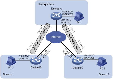
Table 1 Interface and IP address assignment
|
Device |
Interface |
IP address |
|
Device A |
Vlan-int10 |
20.1.1.1/24 |
|
|
Vlan-int20 |
2001::1/64 |
|
|
Tunnel1 |
3001::1/64 |
|
|
Tunnel2 |
4001::1/64 |
|
Device B |
Vlan-int10 |
30.1.1.1/24 |
|
|
Vlan-int20 |
5001::1/64 |
|
|
Tunnel1 |
3001::2/64 |
|
Device C |
Vlan-int10 |
40.1.1.1/24 |
|
|
Vlan-int20 |
6001::1/64 |
|
|
Tunnel2 |
4001::2/64 |
Applicable hardware and software versions
The following matrix shows the hardware and software versions to which this configuration example is applicable:
|
Hardware |
Software version |
|
S6550X-HI switch series |
Release 1116 and later, Release 1213P51 and later |
|
S6880 switch series |
Release 1116 and later, Release 1213P51 and later |
|
S9820-8M switch |
Release 1116 and later, Release 1213P51 and later |
|
S5580X-HI switch series |
Release 1213P50 and later |
|
S5580X-EI switch series |
Release 1213P50 and later |
|
S5580S-EI switch series |
Release 1213P50 and later |
|
S9855 switch series |
Not supported |
|
S9825 switch series |
Not supported |
Restrictions and guidelines
For tunnel interfaces to send and receive packets, you must configure a tunnel-type service loopback group.
On the device, a tunneled packet cannot be directly routed based on its destination address. It is sent to a tunnel-type service loopback group, which then delivers the packet to the forwarding module for Layer 3 forwarding.
Procedures
Make sure the gateways can reach each other at IPv4.
Configuring IPv6 over IPv4 manual tunnels
· Configure Device A:
# Configure an IP address for VLAN-interface 10.
<DeviceA> system-view
[DeviceA] vlan 10
[DeviceA-vlan10] port Twenty-FiveGigE 1/0/1
[DeviceA-vlan10] quit
[DeviceA] interface vlan-interface 10
[DeviceA-Vlan-interface10] ip address 20.1.1.1 24
[DeviceA-Vlan-interface10] quit
# Configure IP addresses for other interfaces, as shown in Figure 1. (Details not shown.)
# Create service loopback group 1, and specify its service type as tunnel.
[DeviceA] service-loopback group 1 type tunnel
# Assign Twenty-FiveGigE 1/0/3 to service loopback group 1.
[DeviceA] interface Twenty-FiveGigE 1/0/3
[DeviceA-Twenty-FiveGigE1/0/3] port service-loopback group 1
[DeviceA-Twenty-FiveGigE1/0/3] quit
# Configure an IPv6 over IPv4 manual tunnel interface Tunnel 1.
[DeviceA] interface tunnel 1 mode ipv6-ipv4
# Configure an IPv6 address for Tunnel 1.
[DeviceA-Tunnel1] ipv6 address 3001::1/64
# Specify VLAN-interface 10 as the source interface of Tunnel 1.
[DeviceA-Tunnel1] source vlan-interface 10
# Specify the destination address for Tunnel 1.
[DeviceA-Tunnel1] destination 30.1.1.1
[DeviceA-Tunnel1] quit
# Configure an IPv6 over IPv4 manual tunnel interface Tunnel 2.
[DeviceA] interface tunnel 2 mode ipv6-ipv4
# Configure an IPv6 address for Tunnel 2.
[DeviceA-Tunnel2] ipv6 address 4001::1/64
# Specify VLAN-interface 10 as the source interface of Tunnel 2.
[DeviceA-Tunnel2] source Vlan-interface 10
# Specify the destination address for Tunnel 2.
[DeviceA-Tunnel2] destination 40.1.1.1
[DeviceA-Tunnel2] quit
· Configure Device B:
# Configure an IP address for VLAN-interface 10.
<DeviceB> system-view
[DeviceB] vlan 10
[DeviceB-vlan10] port Twenty-FiveGigE 1/0/1
[DeviceB-vlan10] quit
[DeviceB] interface vlan-interface 10
[DeviceB-Vlan-interface10] ip address 30.1.1.1 24
[DeviceB-Vlan-interface10] quit
# Configure IP addresses for other interfaces, as shown in Figure 1. (Details not shown.)
# Create service loopback group 1, and specify its service type as tunnel.
[DeviceB] service-loopback group 1 type tunnel
# Assign Twenty-FiveGigE 1/0/3 to service loopback group 1.
[DeviceB] interface Twenty-FiveGigE 1/0/3
[DeviceB-Twenty-FiveGigE1/0/3] port service-loopback group 1
[DeviceB-Twenty-FiveGigE1/0/3] quit
# Configure an IPv6 over IPv4 manual tunnel interface Tunnel 1.
[DeviceB] interface tunnel 1 mode ipv6-ipv4
# Configure an IPv6 address for Tunnel 1.
[DeviceB-Tunnel1] ipv6 address 3001::2/64
# Specify VLAN-interface 10 as the source interface of Tunnel 1.
[DeviceB-Tunnel1] source vlan-interface 10
# Specify the destination address for Tunnel 1.
[DeviceB-Tunnel1] destination 20.1.1.1
[DeviceB-Tunnel1] quit
· Configure Device C:
# Configure an IP address for VLAN-interface 10.
<DeviceC> system-view
[DeviceC] vlan 10
[DeviceC-vlan10] port Twenty-FiveGigE 1/0/1
[DeviceC-vlan10] quit
[DeviceC] interface vlan-interface 10
[DeviceC-Vlan-interface10] ip address 40.1.1.1 24
[DeviceC-Vlan-interface10] quit
# Configure IP addresses for other interfaces, as shown in Figure 1. (Details not shown.)
# Create service loopback group 1, and specify its service type as tunnel.
[DeviceC] service-loopback group 1 type tunnel
# Assign Twenty-FiveGigE 1/0/3 to service loopback group 1.
[DeviceC] interface Twenty-FiveGigE 1/0/3
[DeviceC-Twenty-FiveGigE1/0/3] port service-loopback group 1
[DeviceC-Twenty-FiveGigE1/0/3] quit
# Configure an IPv6 over IPv4 manual tunnel interface Tunnel 2.
[DeviceC] interface tunnel 2 mode ipv6-ipv4
# Configure an IPv6 address for Tunnel 2.
[DeviceC-Tunnel2] ipv6 address 4001::2/64
# Specify VLAN-interface 10 as the source interface of Tunnel 2.
[DeviceC-Tunnel2] source vlan-interface 10
# Specify the destination address for Tunnel 2.
[DeviceC-Tunnel2] destination 20.1.1.1
[DeviceC-Tunnel2] quit
Configuring OSPFv3
· Configure Device A:
# Specify the router ID as 1.1.1.1.
[DeviceA] ospfv3
[DeviceA-ospfv3-1] router-id 1.1.1.1
[DeviceA-ospfv3-1] quit
# Enable OSPFv3 on Tunnel 1.
[DeviceA] interface Tunnel 1
[DeviceA-Tunnel1] ospfv3 1 area 0
[DeviceA-Tunnel1] quit
# Enable OSPFv3 on Tunnel 2.
[DeviceA] interface Tunnel 2
[DeviceA-Tunnel2] ospfv3 1 area 0
[DeviceA-Tunnel2] quit
# Enable OSPFv3 on VLAN-interface 20.
[DeviceA] interface vlan-interface 20
[DeviceA-Vlan-interface20] ospfv3 1 area 0
[DeviceA-Vlan-interface20] quit
· Configure Device B:
# Specify the router ID as 2.2.2.2.
[DeviceB] ospfv3
[DeviceB-ospfv3-1] router-id 2.2.2.2
[DeviceB-ospfv3-1] quit
# Enable OSPFv3 on Tunnel 1.
[DeviceB] interface Tunnel 1
[DeviceB-Tunnel1] ospfv3 1 area 0
[DeviceB-Tunnel1] quit
# Enable OSPFv3 on VLAN-interface 20.
[DeviceB] interface vlan-interface 20
[DeviceB-Vlan-interface20] ospfv3 1 area 0
[DeviceB-Vlan-interface20] quit
· Configure Device C:
# Specify the router ID as 3.3.3.3.
[DeviceC] ospfv3
[DeviceC-ospfv3-1] router-id 3.3.3.3
[DeviceC-ospfv3-1] quit
# Enable OSPFv3 on Tunnel 2.
[DeviceC] interface Tunnel 2
[DeviceC-Tunnel2] ospfv3 1 area 0
[DeviceC-Tunnel2] quit
# Enable OSPFv3 on VLAN-interface 20.
[DeviceC] interface vlan-interface 20
[DeviceC-Vlan-interface20] ospfv3 1 area 0
[DeviceC-Vlan-interface20] quit
Verifying the configuration
# Ping PC 1 from PC 2.
Pinging 2001::3
from 5001::3 with 32 bytes of data:
Reply from 2001::3: bytes=32 time=13ms
Reply from 2001::3: bytes=32 time=1ms
Reply from 2001::3: bytes=32 time=1ms
Reply from 2001::3: bytes=32 time<1ms
Ping statistics for 2001::3:
Packets: Sent = 4, Received = 4, Lost = 0 (0% loss),
Approximate round trip times in milli-seconds:
Minimum = 0ms, Maximum = 13ms, Average = 3ms
The output shows that the ping operation succeeds.
# Ping PC 3 from PC 2.
D:\>ping6 -s 5001::3 6001::3
Pinging 6001::3
from 6001::3 with 32 bytes of data:
Reply from 6001::3: bytes=32 time=13ms
Reply from 6001::3: bytes=32 time=1ms
Reply from 6001::3: bytes=32 time=1ms
Reply from 6001::3: bytes=32 time<1ms
Ping statistics for 6001::3:
Packets: Sent = 4, Received = 4, Lost = 0 (0% loss),
Approximate round trip times in milli-seconds:
Minimum = 0ms, Maximum = 13ms, Average = 3ms
The output shows that the ping operation succeeds.
Configuration files
· Device A:
#
service-loopback group 1 type tunnel
#
ospfv3 1
router-id 1.1.1.1
area 0.0.0.0
#
vlan 10
#
vlan 20
#
interface Vlan-interface10
ip address 20.1.1.1 255.255.255.0
#
interface Vlan-interface20
ospfv3 1 area 0.0.0.0
ipv6 address 2001::1/64
#
interface Twenty-FiveGigE1/0/1
port link-mode bridge
port access vlan 10
#
interface Twenty-FiveGigE1/0/2
port link-mode bridge
port access vlan 20
#
interface Twenty-FiveGigE1/0/3
port link-mode bridge
port service-loopback group 1
#
interface Tunnel1 mode ipv6-ipv4
ospfv3 1 area 0.0.0.0
source Vlan-interface10
destination 30.1.1.1
ipv6 address 3001::1/64
#
interface Tunnel2 mode ipv6-ipv4
ospfv3 1 area 0.0.0.0
source Vlan-interface10
destination 40.1.1.1
ipv6 address 4001::1/64
#
· Device B:
#
service-loopback group 1 type tunnel
#
ospfv3 1
router-id 2.2.2.2
area 0.0.0.0
#
vlan 10
#
vlan 20
#
interface Vlan-interface10
ip address 30.1.1.1 255.255.255.0
#
interface Vlan-interface20
ospfv3 1 area 0.0.0.0
ipv6 address 5001::1/64
#
interface Twenty-FiveGigE1/0/1
port link-mode bridge
port access vlan 10
#
interface Twenty-FiveGigE1/0/2
port link-mode bridge
port access vlan 20
#
interface Twenty-FiveGigE1/0/3
port link-mode bridge
port service-loopback group 1
#
interface Tunnel1 mode ipv6-ipv4
ospfv3 1 area 0.0.0.0
source Vlan-interface10
destination 20.1.1.1
ipv6 address 3001::2/64
#
· Device C:
#
service-loopback group 1 type tunnel
#
ospfv3 1
router-id 3.3.3.3
area 0.0.0.0
#
vlan 10
#
vlan 20
#
interface Vlan-interface10
ip address 40.1.1.1 255.255.255.0
#
interface Vlan-interface20
ospfv3 1 area 0.0.0.0
ipv6 address 6001::1/64
#
interface Twenty-FiveGigE1/0/1
port link-mode bridge
port access vlan 10
#
interface Twenty-FiveGigE1/0/2
port link-mode bridge
port access vlan 20
#
interface Twenty-FiveGigE1/0/3
port link-mode bridge
port service-loopback group 1
#
interface Tunnel2 mode ipv6-ipv4
ospfv3 1 area 0.0.0.0
source Vlan-interface10
destination 20.1.1.1
ipv6 address 4001::2/64
#
