- Table of Contents
-
- 03-Layer 3—IP Services Configuration Examples
- 01-IP Unnumbered Configuration Examples
- 02-Cross-Subnet Dynamic IP Address Allocation Configuration Examples
- 03-GRE with OSPF Configuration Examples
- 04-IPv6 over IPv4 GRE Tunnel Configuration Examples
- 05-IPv6 over IPv4 Manual Tunneling with OSPFv3 Configuration Examples
- 06-ISATAP Tunnel and 6to4 Tunnel Configuration Examples
- 07-DHCP Snooping Configuration Examples
- 08-DHCPv6 Server and DHCPv6 Prefix Client Configuration Examples
- Related Documents
-
| Title | Size | Download |
|---|---|---|
| 01-IP Unnumbered Configuration Examples | 93.66 KB |
Introduction
This document provides IP unnumbered configuration examples.
This feature enables an interface to borrow an IP address from another interface on the device when the borrowing interface does not have any IP addresses. The borrowing interface is called IP unnumbered interface.
Prerequisites
The configuration examples in this document were created and verified in a lab environment, and all the devices were started with the factory default configuration. When you are working on a live network, make sure you understand the potential impact of every command on your network.
This document assumes that you have basic knowledge of IP unnumbered.
Restrictions and guidelines
When you configure IP unnumbered, follow these restrictions and guidelines:
· Loopback interfaces cannot borrow IP addresses of other interfaces.
· An interface cannot borrow an IP address from an unnumbered interface.
Example: Configuring IP unnumbered
Network configuration
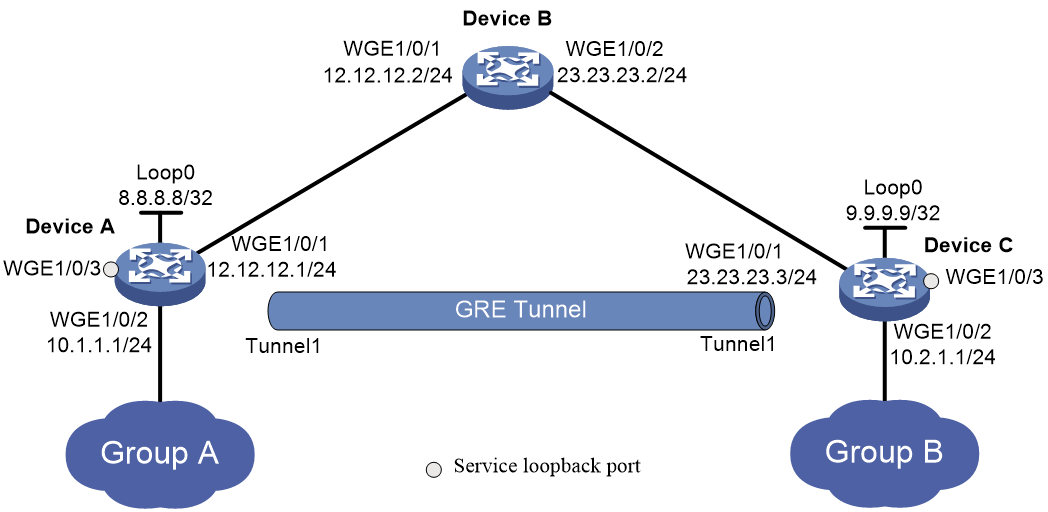
As shown in Figure 1, Group A and Group B are two private IPv4 networks. Device A and Device C will establish a GRE tunnel to interconnect Group 1 and Group 2.
To save IP address space, configure tunnel interface Tunnel 1 to borrow an IP address from the loopback interface loopback 0.
Applicable hardware and software versions
The following matrix shows the hardware and software versions to which this configuration example is applicable:
|
Hardware |
Software version |
|
S6550X-HI switch series |
Release 1116 and later Release 1213P51 and later |
|
S6880 switch series |
Release 1116 and later Release 1213P51 and later |
|
S9820-8M |
Release 1116 and later Release 1213P51 and later |
|
S5580X-HI switch series |
Release 1213P50 and later |
|
S5580X-EI switch series |
Release 1213P50 and later |
|
S5580S-EI switch series |
Release 1213P50 and later |
Procedures
Configuring Device A
1. Assign IP addresses to the interfaces:
# Assign IP addresses to Twenty-FiveGigE 1/0/1 and loopback 0.
<DeviceA> system-view
[DeviceA] interface Twenty-FiveGigE 1/0/1
[DeviceA-Twenty-FiveGigE1/0/1] port link-mode route
[DeviceA-Twenty-FiveGigE1/0/1] ip address 12.12.12.1 24
[DeviceA-Twenty-FiveGigE1/0/1] quit
[DeviceA] interface loopback 0
[DeviceA-LoopBack0] ip address 8.8.8.8 32
[DeviceA-LoopBack0] quit
# Assign IP addresses to other interfaces in the same way an IP address is assigned to Ten-GigabitEthernet 1/0/1. (Details not shown.)
2. Configure OSPF:
[DeviceA] ospf 1
# Create Area 0 and specify Ten-GigabitEthernet 1/0/1 whose IP address is on network 12.12.12.0/24 to run OSPF in Area 0.
[DeviceA-ospf-1] area 0
[DeviceA-ospf-1-area-0.0.0.0] network 12.12.12.0 0.0.0.255
[DeviceA-ospf-1-area-0.0.0.0] quit
[DeviceA-ospf-1] quit
3. Configure a GRE tunnel:
# Create service loopback group 1 and specify the unicast tunnel service for the group.
[DeviceA] service-loopback group 1 type tunnel
# Assign Twenty-FiveGigE 1/0/3 to the service loopback group.
[DeviceA] interface Twenty-FiveGigE 1/0/3
[DeviceA-Twenty-FiveGigE1/0/3] port service-loopback group 1
[DeviceA-Twenty-FiveGigE1/0/3] quit
# Create a tunnel interface Tunnel 1, and specify the tunnel mode as GRE/IPv4.
[DeviceA] interface tunnel 1 mode gre
# Specify 12.12.12.1 as the source address of interface Tunnel 1.
[DeviceA-Tunnel1] source 12.12.12.1
# Specify 23.23.23.3 as the destination address of interface Tunnel 1.
[DeviceA-Tunnel1] destination 23.23.23.3
# Configure interface Tunnel 1 to borrow an IP address from loopback 0.
[DeviceA-Tunnel1] ip address unnumbered interface loopback 0
[DeviceA-Tunnel1] quit
# Configure a static route from Device A through the tunnel interface to Group B.
[DeviceA] ip route-static 10.2.1.0 255.255.255.0 tunnel 1
Configuring Device B
1. Assign IP addresses to the interfaces:
# Assign an IP address to Twenty-FiveGigE 1/0/1.
<DeviceB> system-view
[DeviceB] interface Twenty-FiveGigE 1/0/1
[DeviceB-Twenty-FiveGigE1/0/1] port link-mode route
[DeviceB-Twenty-FiveGigE1/0/1] ip address 12.12.12.2 24
[DeviceB-Twenty-FiveGigE1/0/1] quit
# Assign an IP address to Ten-GigabitEthernet 1/0/2 in the same way an IP address is assigned to Ten-GigabitEthernet 1/0/1. (Details not shown.)
2. Configure OSPF:
# Enable OSPF process 1.
[DeviceB] ospf 1
# Create Area 0 and specify Ten-GigabitEthernet 1/0/1 whose IP address is on network 12.12.12.0/24 to run OSPF in Area 0.
[DeviceB-ospf-1] area 0
[DeviceB-ospf-1-area-0.0.0.0] network 12.12.12.0 0.0.0.255
# Create Area 0 and specify Ten-GigabitEthernet 1/0/2 whose IP address is on network 23.23.23.0/24 to run OSPF in Area 0.
[DeviceB-ospf-1-area-0.0.0.0] network 23.23.23.0 0.0.0.255
[DeviceB-ospf-1-area-0.0.0.0] quit
[DeviceB-ospf-1] quit
Configuring Device C
1. Assign IP addresses to the interfaces:
# Assign IP addresses to Twenty-FiveGigE 1/0/1 and loopback 0.
<DeviceC> system-view
[DeviceC] interface Twenty-FiveGigE 1/0/1
[DeviceC-Twenty-FiveGigE1/0/1] port link-mode route
[DeviceC-Twenty-FiveGigE1/0/1] ip address 23.23.23.3 24
[DeviceC-Twenty-FiveGigE1/0/1] quit
[DeviceC] interface loopback 0
[DeviceC-LoopBack0] ip address 9.9.9.9 32
[DeviceC-LoopBack0] quit
# Assign IP addresses to other interfaces in the same way an IP address is assigned to Ten-GigabitEthernet 1/0/1. (Details not shown.)
2. Configure OSPF:
# Enable OSPF process 1.
[DeviceC] ospf 1
# Create Area 0 and specify Ten-GigabitEthernet 1/0/1 whose IP address is on network 23.23.23.0/24 to run OSPF in Area 0.
[DeviceC-ospf-1] area 0
[DeviceC-ospf-1-area-0.0.0.0] network 23.23.23.0 0.0.0.255
[DeviceC-ospf-1-area-0.0.0.0] quit
[DeviceC-ospf-1] quit
3. Configure a GRE tunnel:
# Create service loopback group 1 and specify the unicast tunnel service for the group.
[DeviceC] service-loopback group 1 type tunnel
# Assign Twenty-FiveGigE 1/0/3 to the service loopback group.
[DeviceC] interface Twenty-FiveGigE 1/0/3
[DeviceC-Twenty-FiveGigE1/0/3] port service-loopback group 1
[DeviceC-Twenty-FiveGigE1/0/3] quit
# Create a tunnel interface Tunnel 1, and specify the tunnel mode as GRE/IPv4.
[DeviceC] interface tunnel 1 mode gre
# Specify 23.23.23.3 as the source address of interface Tunnel 1.
[DeviceC-Tunnel1] source 23.23.23.3
# Specify 12.12.12.1 as the destination address of interface Tunnel 1.
[DeviceC-Tunnel1] destination 12.12.12.1
# Configure interface Tunnel 1 to borrow an IP address from loopback 0.
[DeviceC-Tunnel1] ip address unnumbered interface loopback 0
[DeviceC-Tunnel1] quit
# Configure a static route from Device C through the tunnel interface to Group A.
[DeviceC] ip route-static 10.1.1.0 255.255.255.0 tunnel 1
Verifying the configuration
This example uses Device A to verify the configuration.
# Verify that the interface Tunnel 1 has borrowed the IP address 8.8.8.8/32 from loopback 0.
[DeviceA] display interface tunnel 1
Tunnel1
Current state: UP
Line protocol state: UP
Description: Tunnel1 Interface
Bandwidth: 64kbps
Maximum transmission unit: 1476
Internet Address: 8.8.8.8/32 (Unnumbered)
Tunnel source 12.12.12.1, destination 23.23.23.3
Tunnel keepalive disabled
Tunnel TTL 255
Tunnel protocol/transport GRE/IP
GRE key disabled
Checksumming of GRE packets disabled
Last clearing of counters: Never
Last 300 seconds input rate: 0 bytes/sec, 0 bits/sec, 0 packets/sec
Last 300 seconds output rate: 0 bytes/sec, 0 bits/sec, 0 packets/sec
Input: 11 packets, 924 bytes, 0 drops
Output: 10 packets, 840 bytes, 0 drops
# Verify that Twenty-FiveGigE 1/0/2 on Device A can ping the IP address of Twenty-FiveGigE 1/0/2 on Device C.
# Verify that VLAN-interface 10 on Device A can ping the IP address of VLAN-interface 10 on Device C.
[DeviceA] ping -a 10.1.1.1 10.2.1.1
Ping 10.2.1.1 (10.2.1.1) from 10.1.1.1: 56 data bytes, press CTRL_C to break
56 bytes from 10.2.1.1: icmp_seq=0 ttl=255 time=32.641 ms
56 bytes from 10.2.1.1: icmp_seq=1 ttl=255 time=4.881 ms
56 bytes from 10.2.1.1: icmp_seq=2 ttl=255 time=4.816 ms
56 bytes from 10.2.1.1: icmp_seq=3 ttl=255 time=26.393 ms
56 bytes from 10.2.1.1: icmp_seq=4 ttl=255 time=43.003 ms
--- Ping statistics for 10.2.1.1 ---
5 packet(s) transmitted, 5 packet(s) received, 0.0% packet loss
round-trip min/avg/max/std-dev = 4.816/22.347/43.003/15.241 ms
Configuration files
· Device A:
#
service-loopback group 1 type tunnel
#
ospf 1
area 0.0.0.0
network 12.12.12.0 0.0.0.255
#
vlan 10
#
vlan 12
#
interface LoopBack0
ip address 8.8.8.8 255.255.255.255
#
interface Vlan-interface10
ip address 10.1.1.1 255.255.255.0
#
interface Vlan-interface12
ip address 12.12.12.1 255.255.255.0
#
interface Twenty-FiveGigE1/0/1
port link-mode route
ip address 12.12.12.1 255.255.255.0
#
interface Twenty-FiveGigE1/0/2
port link-mode route
ip address 10.1.1.1 255.255.255.0
#
interface Twenty-FiveGigE1/0/3
port link-mode bridge
port service-loopback group 1
#
interface Tunnel1 mode gre
ip address unnumbered interface LoopBack0
source 12.12.12.1
destination 23.23.23.3
#
ip route-static 10.2.1.0 24 Tunnel1
#
· Device B:
#
ospf 1
area 0.0.0.0
network 12.12.12.0 0.0.0.255
network 23.23.23.0 0.0.0.255
#
vlan 12
#
vlan 23
#
interface Vlan-interface12
ip address 12.12.12.2 255.255.255.0
#
interface Vlan-interface23
ip address 23.23.23.3 255.255.255.0
#
interface Twenty-FiveGigE/0/1
port link-mode route
ip address 12.12.12.2 255.255.255.0
#
interface Twenty-FiveGigE1/0/2
port link-mode route
ip address 23.23.23.2 255.255.255.0
#
· Device C:
#
service-loopback group 1 type tunnel
#
ospf 1
area 0.0.0.0
network 23.23.23.0 0.0.0.255
#
vlan 10
#
vlan 23
#
interface LoopBack0
ip address 9.9.9.9 255.255.255.255
#
interface Vlan-interface10
ip address 10.2.1.1 255.255.255.0
#
interface Vlan-interface23
ip address 23.23.23.3 255.255.255.0
#
interface Twenty-FiveGigE1/0/1
port link-mode route
ip address 23.23.23.3 255.255.255.0
#
interface Twenty-FiveGigE1/0/2
port link-mode route
ip address 10.2.1.1 255.255.255.0
#
interface Twenty-FiveGigE1/0/3
port link-mode bridge
port service-loopback group 1
#
interface Tunnel1 mode gre
ip address unnumbered interface LoopBack0
source 23.23.23.3
destination 12.12.12.1
#
ip route-static 10.1.1.0 24 Tunnel1
#
