- Table of Contents
-
- H3C Wi-Fi7 Indoor Access Points Installation Guide-5W102
- 00-Preface
- 01-Installing the device
- 02-Logging in to the device
- 03-Appendix A AP views and technical specifications
- 04-Appendix B LEDs and buttons
- 05-Appendix C Optional transceiver modules
- 06-Appendix D Connecting the hybrid copper-fiber cable
- 07-Appendix E Cabling recommendations
- Related Documents
-
| Title | Size | Download |
|---|---|---|
| 06-Appendix D Connecting the hybrid copper-fiber cable | 1.96 MB |
6 Appendix D Connecting the hybrid copper-fiber cable
About the hybrid copper-fiber cable
Difference between main cable, pigtail cord, and fiber jumper
Fusion splicing an optical fiber
Fusion splicing an optical fiber
Splicing copper wires by using bare crimp terminals
Splicing copper wires with common DC wire terminals
6 Appendix D Connecting the hybrid copper-fiber cable
About the hybrid copper-fiber cable
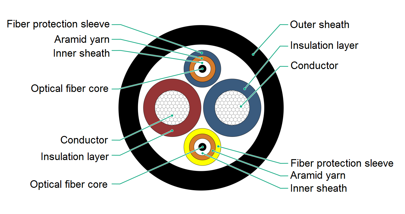
A hybrid copper-fiber cable is a cable that integrates optical fiber and conductive copper wire. The structure of the hybrid copper-fiber cable is shown in Figure6-1.
Figure6-1 Cross-section of the hybrid copper-fiber cable
Application scenarios
A hybrid copper-fiber cable connects a switch and a powered device, for example, an AP for AC power supply and optical fiber communication. This can reduce cabling costs.
A hybrid copper-fiber cable contains the pigtail cord at the switch, the main cable, and the pigtail cord at the powered device side. You must fusion splice the main cable and the pigtail cords on site.
Figure6-2 Fusion splicing points
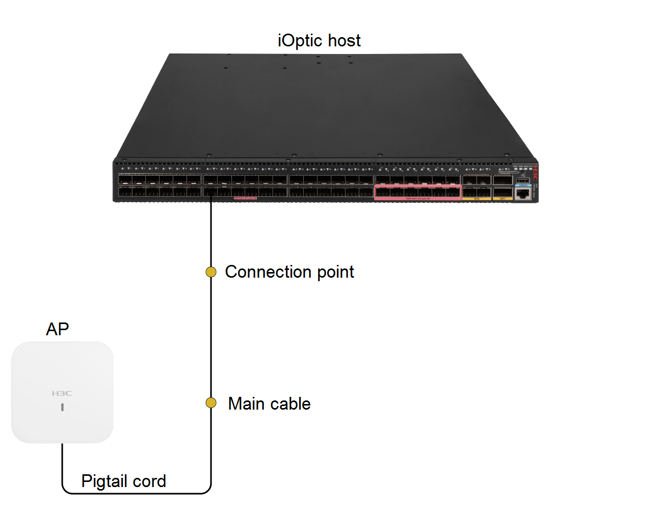
The two optical fibers of the main cable must be spliced crosswise with the optical fibers of the pigtail cord. As a best practice, fusion splice the optical fibers of the same color at the switch side, and fusion splice the optical fibers of different colors at the powered device side.
Difference between main cable, pigtail cord, and fiber jumper
Main cable of the hybrid copper-fiber cable
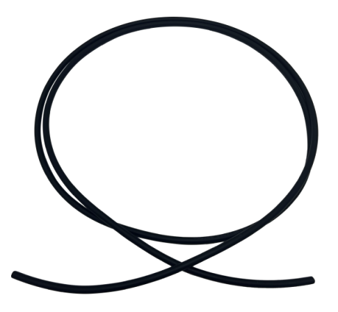
The main cable is used for long-distance cabling from the switch to powered devices. There are no connectors at both ends of the cable. You can select main cables as needed.
Figure6-3 Main cable
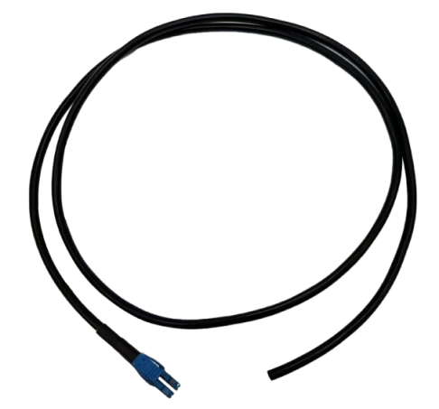
Pigtail cord
A pigtail cord is used for connecting a powered device. The two optical fibers and two copper wires are connected to the corresponding optical fibers and copper wires in the main cable, respectively. The pigtail cord has an optical-electric hybrid connector at one end.
Figure6-4 Pigtail cord
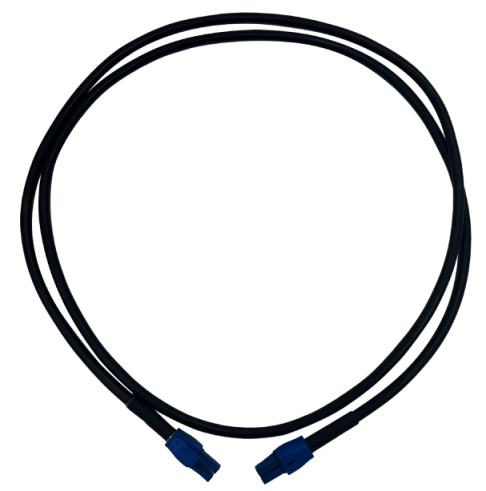
Jumper
For standard and neat cabling in the equipment room, you can use fiber jumpers. A fiber jumper has an optical-electric hybrid connector at both ends.
Figure6-5 Jumper
Fusion splicing an optical fiber
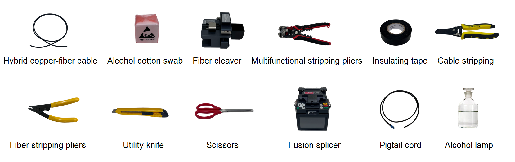
Tools
The following tools are required for optical fiber fusion splicing. Prepare the tools yourself.
Hybrid copper-fiber cable, alcohol cotton swab, fiber cleaver, multifunctional stripping pliers, insulating tape, cable stripping pliers, fiber stripping pliers, utility knife, scissors, fusion splicer, pigtail cord, and alcohol lamp.
Figure6-6 Fusion splicing tools
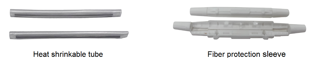
Fusion splicing accessories
The following accessories are required for optical fiber fusion splicing. Prepare the accessories yourself.
Figure6-7 Fusion splicing accessories

Fusion splicing an optical fiber
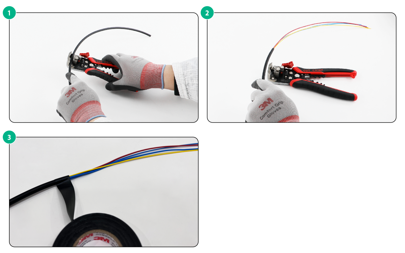
Stripping a hybrid copper-fiber cable
1. Strip the rubber protective cover to an appropriate length based on the current installation scenario.
2. Separate the optical fiber cable and power cable from the hybrid copper-fiber cable.
3. Use insulating tape to protect the other side of the hybrid copper-fiber cable to prevent the outer jacket of the cable from cracking.
Figure6-8 Stripping a hybrid copper-fiber cable
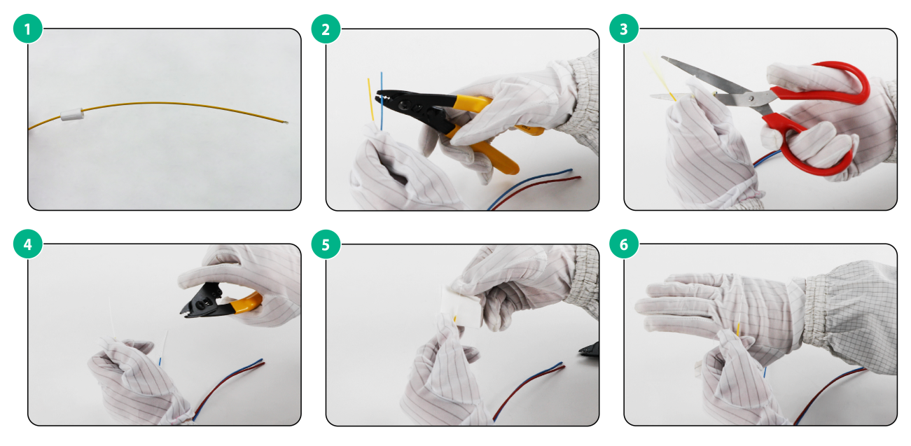
Stripping an optical fiber
1. Take out the two optical fibers from the stripped hybrid copper-fiber cable.
2. Thread the optical fiber protective sleeve onto the optical fiber to be stripped and secure it with a nut.
3. Use wire strippers to peel off the outer sheath of the optical fiber and cut off the excess aramid yarn.
4. Use a wire stripper to peel off the inner sheath and insulation layer of the optical fiber.
5. Use alcohol cotton swabs to clean and erase the insulation residue from the fiber core.
To avoid twisting the optical fiber core, peel off the inner sheath and insulation layer of the optical fiber in small sections.
Figure6-9 Stripping an optical fiber
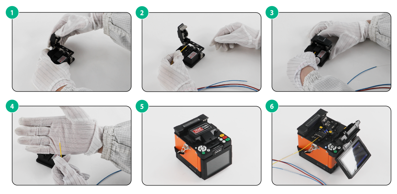
Cleaving optical fibers
Cut the optical fiber end after cleaning the fiber core to ensure smooth fusion process.
1. Open the clamp cover and fiber holder lid.
2. Place the prepared fiber in the fiber holder groove, and close the clamp cover and fiber holder lid.
3. Push the blade carriage sliding block forward firmly.
4. Open the cover on the left side of the fusion splicer and put the fibers into the fiber holders in the fusion splicer. Close the cover.
If the fiber end is not flat, perform the previous steps again.
Figure6-10 Cleaving optical fibers
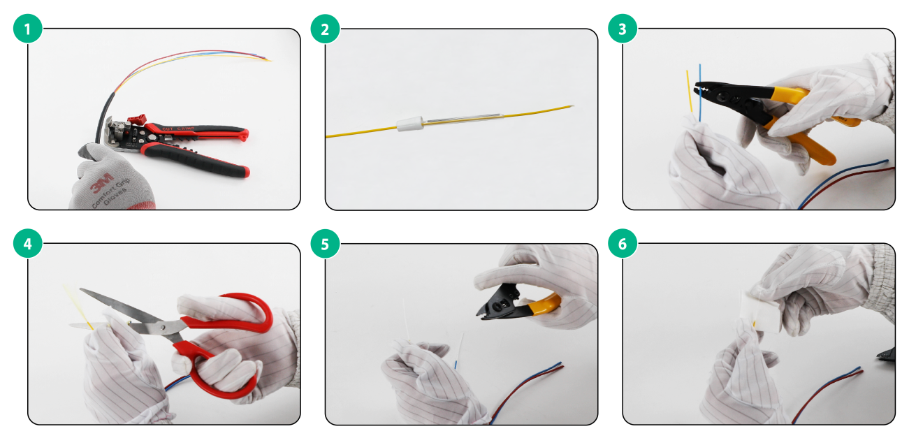
Stripping a pigtail cord
1. Separate two optical fibers from the stripped pigtail cord.
2. Thread one optical fiber in the pigtail cord into the protective sleeve and the heat shrink tube in turn.
3. Use wire strippers to peel off the outer sheath of the optical fiber, cut off the excess aramid yarn, and then peel off the inner sheath and insulation layer of the optical fiber.
4. Use alcohol cotton swabs to clean and erase the insulation residue from the fiber core.
Figure6-11 Stripping a pigtail cord
Cleaving the pigtail cord
The procedure is the same as cleaving the main cable. For more information, see "Cleaving optical fibers."
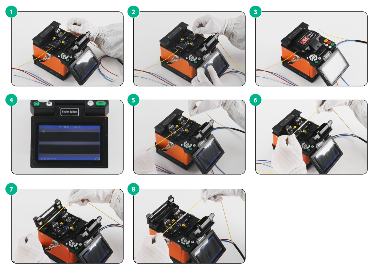
Fusion splicing an optical fiber
1. Open the clamp cover on the right side of the fusion splicer and put the pigtail cords into the fiber holders in the fusion splicer. Close the clamp cover.
2. Close the fusion splicer cover, and the fusion splicer starts to work.
3. Observe the monitor on the fusion splicer. The monitor is shown as follows when fusion splicing succeeds.
4. After the optical fibers are fusion spliced successfully, open the clamp cover and remove the spliced fibers.
5. Open the heater clamp, slide the heat shrink tube over the spliced fiber, place the spliced fiber in the heater, and close the heater clamp. When the HEAT LED turns off, heat shrinking has finished.
Figure6-12 Fusion splicing an optical fiber
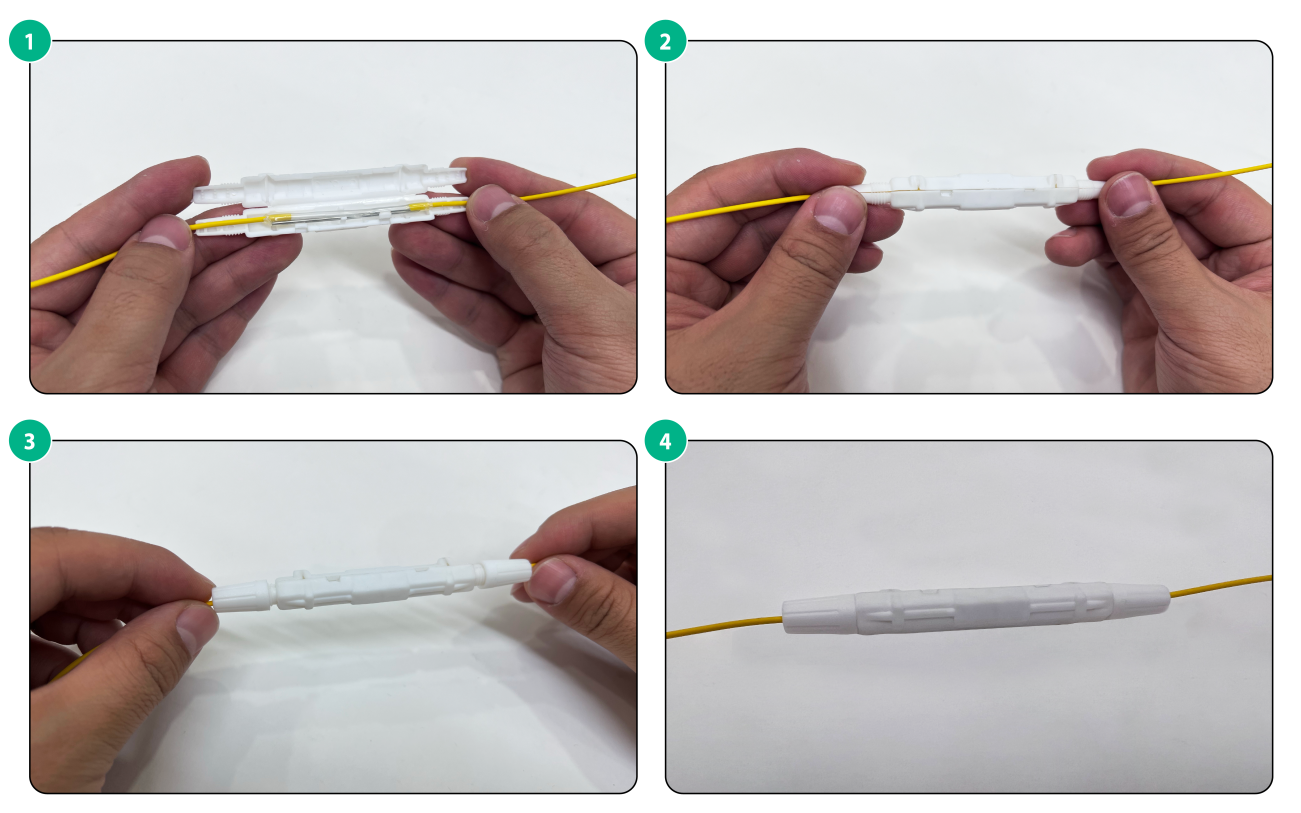
(Optional) Installing the fusion splice protection sleeve
After fusion splicing is complete, put the heat shrinking tube in the fusion splice protection sleeve. If other protections are available, for example, a weak current cabinet or fiber patch panel, no fusion splice protection sleeve is required.
Figure6-13 Installing the fusion splice protection sleeve
Splicing copper wires
Splicing copper wires by using bare crimp terminals
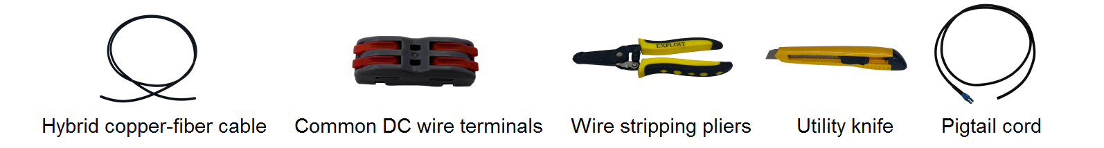
Splicing tools
The following tools are required for splicing copper wires. Prepare the tools yourself.
Figure6-14 Splicing tools
Stripping copper wires
1. Strip the pigtail to separate the two wires from the cable.
2. Peel off the insulation coating from the wires. Make sure you peel off 9 to 10 mm (0.35 to 0.39 in) of insulation coating.
3. Separate two power wires from the hybrid copper-fiber cable.
4. Peel off the insulation coating from the wires. Make sure you peel off 9 to 10 mm (0.35 to 0.39 in) of insulation coating.
The procedure is the same for stripping the copper wires on the other end of the hybrid copper-fiber cable and pigtail cord.
Figure6-15 Stripping copper wires
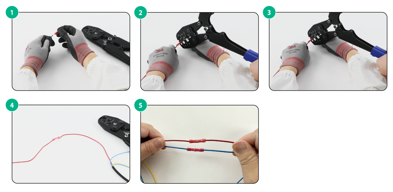
Splicing copper wires
1. Insert copper wires from the main cable into the left part on the bare crimp terminal.
2. Use a crimping tool to crimp the wires.
3. Insert copper wires from the pigtail into the right part on the bare crimp terminal.
4. Use a crimping tool to crimp the wires.
5. Gently pull both ends of the crimped copper wire to ensure firm splicing.
Make sure you splice copper wires of the same color from the main cable and the pigtail.
Figure6-16 Splicing copper wires
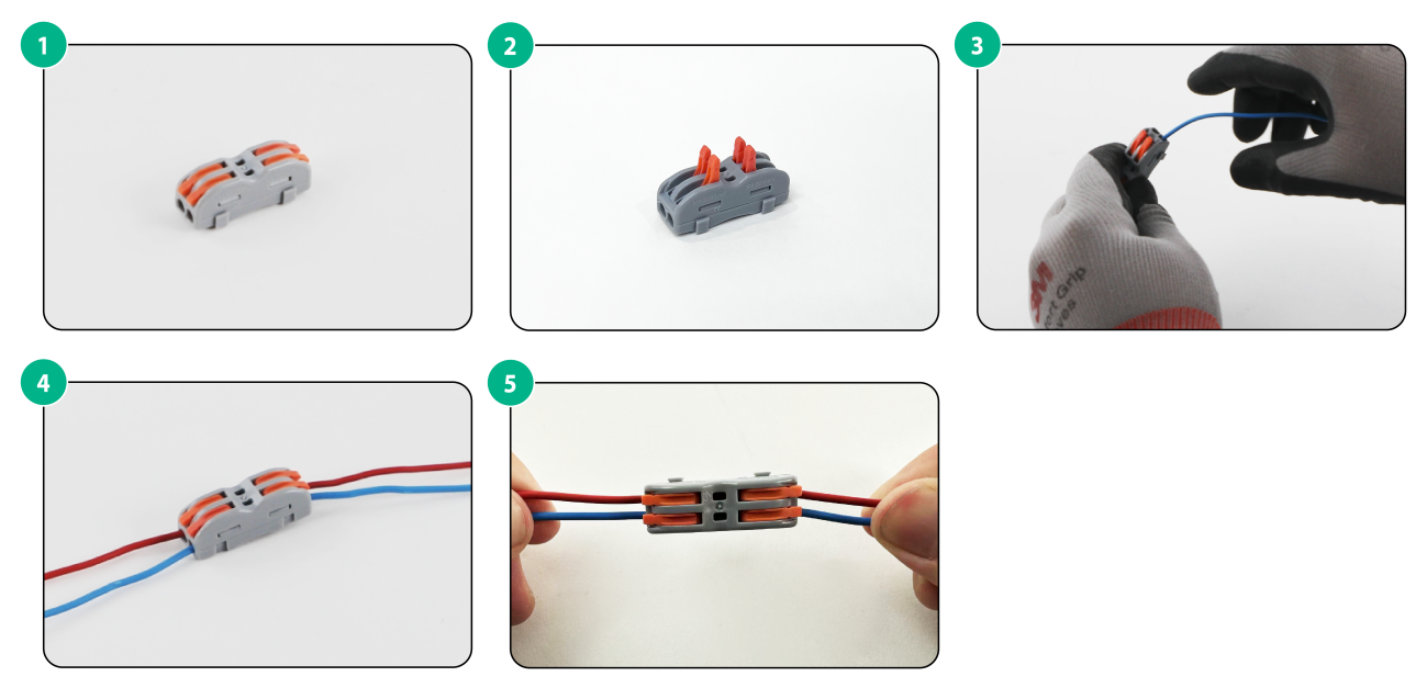
Splicing copper wires with common DC wire terminals
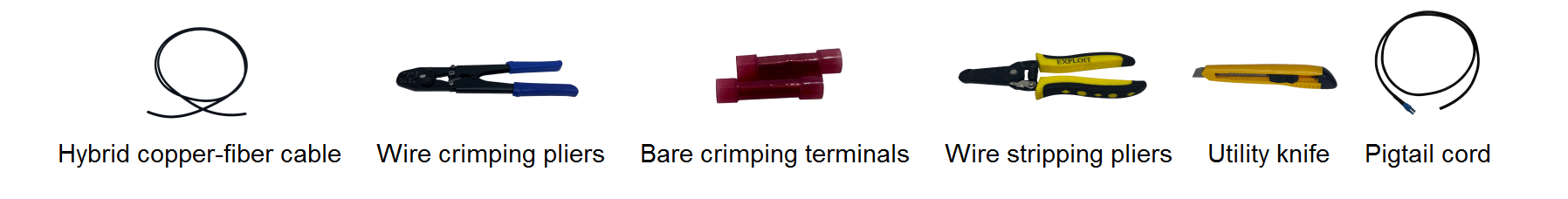
Splicing tools
The following tools are required for splicing copper wires with common DC wire terminals. Prepare the tools yourself.
Figure6-17 Splicing tools
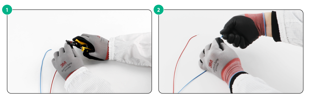
Stripping copper wires
1. Strip the pigtail to separate the two wires from the cable.
2. Peel off the insulation coating the wires. Make sure you peel off 9 to 10 mm (0.35 to 0.39 in) of insulation coating.
3. Separate two power wires from the hybrid copper-fiber cable.
4. Peel off the insulation coating from the wires. Make sure you peel off 9 to 10 mm (0.35 to 0.39 in) of insulation coating.
The procedure is the same for stripping the copper wires on the other end of the hybrid copper-fiber cable and pigtail cord.
Figure6-18 Stripping copper wires

Splicing copper wires
1. Lift up the four levers.
2. Insert copper wires from the main cable and the pigtail into the left part on the bare crimp terminal.
3. Press the levers closed.
4. Gently pull both ends of the crimped copper wires to ensure firm splicing.
Make sure you splice copper wires of the same color from the main cable and the pigtail.
Figure6-19 Splicing copper wires