- Table of Contents
-
- 02-Layer 2—LAN Switching Configuration Examples
- 01-MAC Address Table Configuration Examples
- 02-Ethernet Link Aggregation Configuration Examples
- 03-Port Isolation Configuration Examples
- 04-VLAN Configuration Examples
- 05-VLAN Tagging Configuration Examples
- 06-S-MLAG Configuration Examples
- 07-Spanning Tree Configuration Examples
- Related Documents
-
| Title | Size | Download |
|---|---|---|
| 03-Port Isolation Configuration Examples | 60.46 KB |
Contents
General configuration restrictions and guidelines
Example: Configuring port isolation
Applicable hardware and software versions
Introduction
This document provides port isolation configuration examples.
Prerequisites
This document is not restricted to specific software or hardware versions.
The configuration examples in this document were created and verified in a lab environment, and all the devices were started with the factory default configuration. When you are working on a live network, make sure you understand the potential impact of every command on your network.
This document assumes that you have basic knowledge of port isolation.
General configuration restrictions and guidelines
You cannot assign the member ports of a service loopback group to an isolation group. You cannot assign the member ports of an isolation group to a service loopback group.
Example: Configuring port isolation
Network configuration
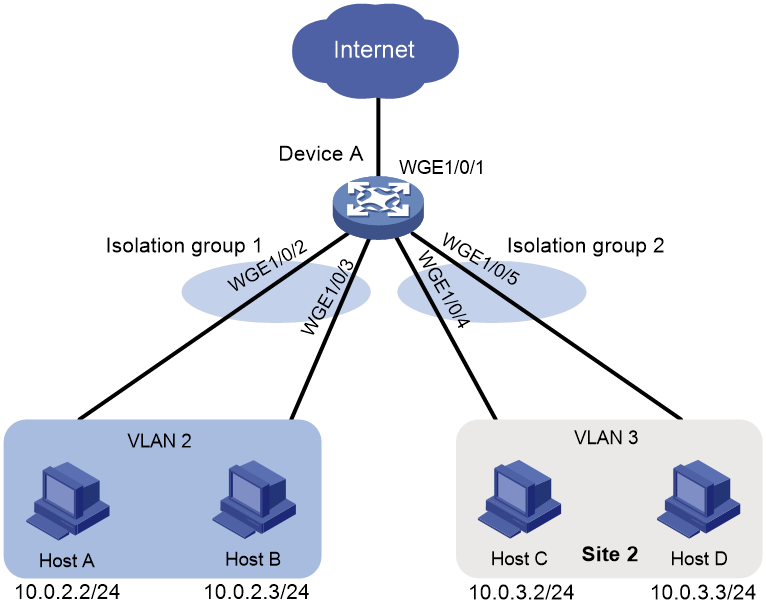
As shown in Figure 1, the company branches Site 1 and Site 2 transfer service traffic in VLAN 2 and VLAN 3. Device A connects to the Internet through Twenty-FiveGigE 1/0/1.
Configure port isolation on Device A to meet the following requirements:
· All hosts can access the Internet through Device A.
· Host A and Host B are isolated from each other at Layer 2.
· Host C and Host D are isolated from each other at Layer 2.
Applicable hardware and software versions
The following matrix shows the hardware and software versions to which this configuration example is applicable:
|
Hardware |
Software version |
|
S6550X-HI switch series |
Release 1116 and later |
|
S6880 switch series |
Release 1116 and later |
|
S9820-8M switch |
Release 1116 and later |
|
S9855 switch series |
Not supported |
|
S9825 switch series |
Not supported |
Restrictions and guidelines
When you configure port isolation on the device, follow these restrictions and guidelines:
· Before assigning a port to an isolation group, make sure the isolation group already exists.
· You can assign a port to only one isolation group.
Procedures
# Create VLAN 2 and assign ports Twenty-FiveGigE 1/0/2 and Twenty-FiveGigE 1/0/3 to the VLAN.
<DeviceA> system-view
[DeviceA] vlan 2
[DeviceA-vlan2] port twenty-fivegige 1/0/2
[DeviceA-vlan2] port twenty-fivegige 1/0/3
[DeviceA-vlan2] quit
# Create VLAN 3 and assign ports Twenty-FiveGigE 1/0/4 and Twenty-FiveGigE 1/0/5 to the VLAN.
[DeviceA] vlan 3
[DeviceA-vlan3] port twenty-fivegige 1/0/4
[DeviceA-vlan3] port twenty-fivegige 1/0/5
[DeviceA-vlan3] quit
# Configure port Twenty-FiveGigE 1/0/1 as a trunk port and assign it to VLAN 2 and VLAN 3.
[DeviceA] interface twenty-fivegige 1/0/1
[DeviceA-Twenty-FiveGigE1/0/1] port link-type trunk
[DeviceA-Twenty-FiveGigE1/0/1] port trunk permit vlan 2 3
[DeviceA-Twenty-FiveGigE1/0/1] quit
# Create isolation groups 1 and 2.
[DeviceA] port-isolate group 1
[DeviceA] port-isolate group 2
# Assign ports Twenty-FiveGigE 1/0/2 and Twenty-FiveGigE 1/0/3 to isolation group 1.
[DeviceA] interface twenty-fivegige 1/0/2
[DeviceA-Twenty-FiveGigE1/0/2] port-isolate enable group 1
[DeviceA-Twenty-FiveGigE1/0/2] quit
[DeviceA] interface twenty-fivegige 1/0/3
[DeviceA-Twenty-FiveGigE1/0/3] port-isolate enable group 1
[DeviceA-Twenty-FiveGigE1/0/3] quit
# Assign ports Twenty-FiveGigE 1/0/4 and Twenty-FiveGigE 1/0/5 to isolation group 2.
[DeviceA] interface twenty-fivegige 1/0/4
[DeviceA-Twenty-FiveGigE1/0/4] port-isolate enable group 2
[DeviceA-Twenty-FiveGigE1/0/4] quit
[DeviceA] interface twenty-fivegige 1/0/5
[DeviceA-Twenty-FiveGigE1/0/5] port-isolate enable group 2
[DeviceA-Twenty-FiveGigE1/0/5] quit
Verifying the configuration
# Display information about all isolation groups.
[DeviceA] display port-isolate group
Port isolation group information:
Group ID: 1
Group members:
Twenty-FiveGigE1/0/2
Twenty-FiveGigE1/0/3
Group ID: 2
Group members:
Twenty-FiveGigE1/0/4
Twenty-FiveGigE1/0/5
The output shows that:
· Ports Twenty-FiveGigE 1/0/2 and Twenty-FiveGigE 1/0/3 are in isolation group 1. As a result, Host A and Host B are isolated from each other at Layer 2.
· Ports Twenty-FiveGigE 1/0/4 and Twenty-FiveGigE 1/0/4 are in isolation group 2. As a result, Host C and Host D are isolated from each other at Layer 2.
Configuration files
port-isolate group 1
port-isolate group 2
#
vlan 2 to 3
#
interface Twenty-FiveGigE1/0/1
port link-mode bridge
port link-type trunk
port trunk permit vlan 1 to 3
#
interface Twenty-FiveGigE1/0/2
port link-mode bridge
port access vlan 2
port-isolate enable group 1
#
interface Twenty-FiveGigE1/0/3
port link-mode bridge
port access vlan 2
port-isolate enable group 1
#
interface Twenty-FiveGigE1/0/4
port link-mode bridge
port access vlan 3
port-isolate enable group 2
#
interface Twenty-FiveGigE1/0/5
port link-mode bridge
port access vlan 3
port-isolate enable group 2
#
