- Table of Contents
-
- 02-Layer 2—LAN Switching Configuration Examples
- 01-MAC Address Table Configuration Examples
- 02-Ethernet Link Aggregation Configuration Examples
- 03-Port Isolation Configuration Examples
- 04-VLAN Configuration Examples
- 05-VLAN Tagging Configuration Examples
- 06-S-MLAG Configuration Examples
- 07-Spanning Tree Configuration Examples
- Related Documents
-
| Title | Size | Download |
|---|---|---|
| 02-Ethernet Link Aggregation Configuration Examples | 142.18 KB |
Example: Configuring Layer 2 link aggregation
Applicable hardware and software versions
Example: Configuring Layer 2 link aggregation load sharing
Applicable hardware and software versions
Example: Configuring Layer 3 link aggregation
Applicable hardware and software versions
Example: Configuring Layer 3 link aggregation load sharing
Applicable hardware and software versions
Introduction
This document provides Ethernet link aggregation configuration examples.
Prerequisites
The configuration examples in this document were created and verified in a lab environment, and all the devices were started with the factory default configuration. When you are working on a live network, make sure you understand the potential impact of every command on your network.
This document assumes that you have basic knowledge of Ethernet link aggregation.
Example: Configuring Layer 2 link aggregation
Network configuration
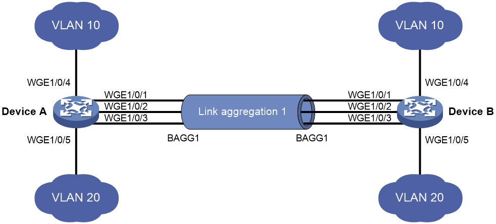
As shown in Figure 1, both Device A and Device B forward traffic from VLAN 10 and VLAN 20.
Configure link aggregation on Device A and Device B to meet the following requirements:
· VLAN 10 on Device A can communicate with VLAN 10 on Device B.
· VLAN 20 on Device A can communicate with VLAN 20 on Device B.
Analysis
To enable traffic from VLAN 10 and VLAN 20 to pass through Layer 2 aggregate interface Bridge-aggregation 1, perform the following tasks:
· Configure Layer 2 aggregate interface Bridge-aggregation 1 as a trunk port.
· Assign the aggregate interface to VLAN 10 and VLAN 20.
Applicable hardware and software versions
The following matrix shows the hardware and software versions to which this configuration example is applicable:
|
Hardware |
Software version |
|
S6550X-HI switch series |
Release 1116 and later |
|
S6880 switch series |
Release 1116 and later |
|
S9820-8M switch |
Release 1116 and later |
|
S9855 switch series |
Release 9126 and later |
|
S9825 switch series |
Release 9126 and later |
Restrictions and guidelines
When you configure Layer 2 link aggregation, follow these restrictions and guidelines:
· When you assign a port to an aggregation group, the recommended configuration procedure is as follows:
a. Use the display this command in interface view to check the following attribute configurations of the port:
- Port isolation.
- QinQ.
- VLAN.
- VLAN mapping.
b. If any of the above configurations exist, use the undo forms of the corresponding commands to remove these configurations. This enables the port to use the default attribute configurations.
c. Assign the port to the aggregation group.
· In a static aggregation group, the Selected state of a port is not affected by whether the peer port is added to an aggregation group and is Selected. As a result, the Selected state of a port might be different from the Selected state of the peer port. When both ends support static aggregation and dynamic aggregation, HP recommends using dynamic aggregation.
· You cannot assign a port to a Layer 2 aggregation group when MAC authentication, port security mode, or 802.1X is configured or enabled on the port.
Procedures
1. Configure Device A:
# Create VLAN 10, and assign port Twenty-FiveGigE 1/0/4 to VLAN 10.
<DeviceA> system-view
[DeviceA] vlan 10
[DeviceA-vlan10] port twenty-fivegige 1/0/4
[DeviceA-vlan10] quit
# Create VLAN 20, and assign port Twenty-FiveGigE 1/0/5 to VLAN 20.
[DeviceA] vlan 20
[DeviceA-vlan20] port twenty-fivegige 1/0/5
[DeviceA-vlan20] quit
# Create Layer 2 aggregate interface Bridge-aggregation 1. Use one of the following methods as needed.
¡ Use the static aggregation mode to create Layer 2 aggregate interface Bridge-aggregation 1.
[DeviceA] interface bridge-aggregation 1
[DeviceA-Bridge-Aggregation1] undo shutdown
[DeviceA-Bridge-Aggregation1] quit
¡ Use the dynamic aggregation mode to create Layer 2 aggregate interface Bridge-aggregation 1.
[DeviceA] interface bridge-aggregation 1
[DeviceA-Bridge-Aggregation1] link-aggregation mode dynamic
[DeviceA-Bridge-Aggregation1] undo shutdown
[DeviceA-Bridge-Aggregation1] quit
# Assign ports Twenty-FiveGigE 1/0/1 through Twenty-FiveGigE 1/0/3 to aggregation group 1.
[DeviceA] interface range twenty-fivegige 1/0/1 to twenty-fivegige 1/0/3
[DeviceA-if-range] port link-aggregation group 1
[DeviceA-if-range] undo shutdown
[DeviceA-if-range] quit
# Configure Layer 2 aggregate interface Bridge-aggregation 1 as a trunk port.
[DeviceA] interface bridge-aggregation 1
[DeviceA-Bridge-Aggregation1] port link-type trunk
Configuring Twenty-FiveGigE1/0/1 done.
Configuring Twenty-FiveGigE1/0/2 done.
Configuring Twenty-FiveGigE1/0/3 done.
# Assign the aggregate interface to VLANs 10 and 20.
[DeviceA-Bridge-Aggregation1] port trunk permit vlan 10 20
Configuring Twenty-FiveGigE1/0/1 done.
Configuring Twenty-FiveGigE1/0/2 done.
Configuring Twenty-FiveGigE1/0/3 done.
[DeviceA-Bridge-Aggregation1] quit
2. Configure Device B in the same way Device A is configured. (Details not shown.)
Verifying the configuration
# Display detailed information about the link aggregation groups on Device A.
· Link aggregation configuration information when the static aggregation mode is used:
[DeviceA] display link-aggregation verbose
Loadsharing Type: Shar -- Loadsharing, NonS -- Non-Loadsharing
Port Status: S -- Selected, U -- Unselected, I -- Individual
Port: A -- Auto port, M -- Management port, R -- Reference port
Flags: A -- LACP_Activity, B -- LACP_Timeout, C -- Aggregation,
D -- Synchronization, E -- Collecting, F -- Distributing,
G -- Defaulted, H -- Expired
Aggregation Interface: Bridge-Aggregation1
Aggregation Mode: Static
Loadsharing Type: Shar
Management VLANs: None
Port Status Priority Oper-Key
WGE1/0/1(R) S 32768 1
WGE1/0/2 S 32768 1
WGE1/0/3 S 32768 1
The output shows that all member ports in the local aggregation group are in the Selected state. The Selected states of the local member ports are not affected by the Selected states of the peer member ports.
· Link aggregation configuration information when the dynamic aggregation mode is used:
[DeviceA] display link-aggregation verbose
Loadsharing Type: Shar -- Loadsharing, NonS -- Non-Loadsharing
Port Status: S -- Selected, U -- Unselected, I -- Individual
Port: A -- Auto port, M -- Management port, R -- Reference port
Flags: A -- LACP_Activity, B -- LACP_Timeout, C -- Aggregation,
D -- Synchronization, E -- Collecting, F -- Distributing,
G -- Defaulted, H -- Expired
Aggregation Interface: Bridge-Aggregation1
Creation Mode: Manual
Aggregation Mode: Dynamic
Loadsharing Type: Shar
Management VLANs: None
System ID: 0x8000, 000f-e234-5678
Local:
Port Status Priority Index Oper-Key Flag
WGE1/0/1 S 32768 2 1 {ACDEF}
WGE1/0/2 S 32768 3 1 {ACDEF}
WGE1/0/3 S 32768 4 1 {ACDEF}
Remote:
Actor Priority Index Oper-Key SystemID Flag
WGE1/0/1(R) 32768 2 1 0x8000, a4e5-c316-0100 {ACDEF}
WGE1/0/2 32768 3 1 0x8000, a4e5-c316-0100 {ACDEF}
WGE1/0/3 32768 4 1 0x8000, a4e5-c316-0100 {ACDEF}
The output shows that the local member ports and the corresponding peer member ports are all Selected. In the dynamic link aggregation mode, each local member port and its peer member port have the same Selected state through exchanging LACPDUs. The user data traffic can be forwarded correctly.
Configuration files
· Device A:
#
vlan 10
#
interface Twenty-FiveGigE1/0/4
port link-mode bridge
port access vlan 10
#
vlan 20
#
interface Twenty-FiveGigE1/0/5
port link-mode bridge
port access vlan 20
¡ In the static aggregation mode:
#
interface Bridge-Aggregation1
port link-type trunk
port trunk permit vlan 10 20
¡ In the dynamic aggregation mode:
#
interface Bridge-Aggregation1
port link-type trunk
port trunk permit vlan 10 20
link-aggregation mode dynamic
#
interface Twenty-FiveGigE1/0/1
port link-mode bridge
port link-type trunk
port trunk permit vlan 10 20
port link-aggregation group 1
#
interface Twenty-FiveGigE1/0/2
port link-mode bridge
port link-type trunk
port trunk permit vlan 10 20
port link-aggregation group 1
#
interface Twenty-FiveGigE1/0/3
port link-mode bridge
port link-type trunk
port trunk permit vlan 10 20
port link-aggregation group 1
#
· Device B:
The configuration file on Device B is the same as the configuration file on Device A.
Example: Configuring Layer 2 link aggregation load sharing
Network configuration
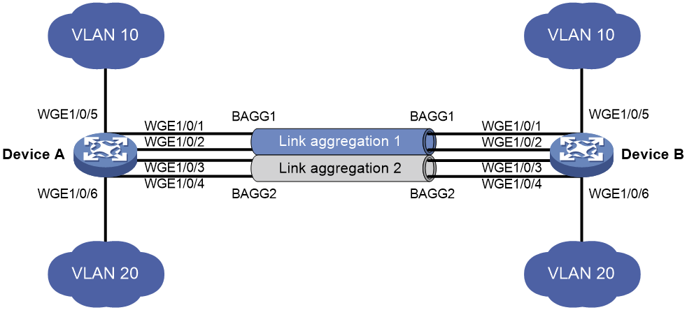
As shown in Figure 2, both Device A and Device B forward traffic from VLAN 10 and VLAN 20.
Configure link aggregation on Device A and Device B to meet the following requirements:
· VLAN 10 on Device A can communicate with VLAN 10 on Device B. VLAN 20 on Device A can communicate with VLAN 20 on Device B.
· The packets from VLAN 10 are load shared across the Selected ports of link aggregation group 1 by source MAC addresses. The packets from VLAN 20 are load shared across the Selected ports of link aggregation group 2 by source MAC addresses.
Analysis
To enable packets from VLAN 10 to pass through aggregate interface Bridge-aggregation 1, assign the aggregate interface to VLAN 10. To enable packets from VLAN 20 to pass through aggregate interface Bridge-aggregation 2, assign the aggregate interface to VLAN 20.
Applicable hardware and software versions
The following matrix shows the hardware and software versions to which this configuration example is applicable:
|
Hardware |
Software version |
|
S6550X-HI switch series |
Release 1116 and later |
|
S6880 switch series |
Release 1116 and later |
|
S9820-8M switch |
Release 1116 and later |
|
S9855 switch series |
Release 9126 and later |
|
S9825 switch series |
Release 9126 and later |
Restrictions and guidelines
When you configure Layer 2 load sharing, follow these restrictions and guidelines:
· When you assign a port to an aggregation group, the recommended configuration procedure is as follows:
a. Use the display this command in interface view to check the following attribute configurations of the port:
- Port isolation.
- QinQ.
- VLAN.
- VLAN mapping.
b. If any of the above configurations exist, use the undo forms of the corresponding commands to remove these configurations. This enables the port to use the default attribute configurations.
c. Assign the port to the aggregation group.
· You cannot assign a port to a Layer 2 aggregation group when MAC authentication, port security mode, or 802.1X is configured or enabled on the port.
Procedures
1. Configure Device A:
# Create VLAN 10, and assign port Twenty-FiveGigE 1/0/5 to VLAN 10.
<DeviceA> system-view
[DeviceA] vlan 10
[DeviceA-vlan10] port twenty-fivegige 1/0/5
[DeviceA-vlan10] quit
# Create VLAN 20, and assign port Twenty-FiveGigE 1/0/6 to VLAN 20.
[DeviceA] vlan 20
[DeviceA-vlan20] port twenty-fivegige 1/0/6
[DeviceA-vlan20] quit
# Create Layer 2 aggregate interface Bridge-aggregation 1.
[DeviceA] interface bridge-aggregation 1
[DeviceA-Bridge-Aggregation1] quit
# Assign ports Twenty-FiveGigE 1/0/1 and Twenty-FiveGigE 1/0/2 to aggregation group 1.
[DeviceA] interface twenty-fivegige 1/0/1
[DeviceA-Twenty-FiveGigE1/0/1] port link-aggregation group 1
[DeviceA-Twenty-FiveGigE1/0/1] quit
[DeviceA] interface twenty-fivegige 1/0/2
[DeviceA-Twenty-FiveGigE1/0/2] port link-aggregation group 1
[DeviceA-Twenty-FiveGigE1/0/2] quit
# Assign Layer 2 aggregate interface Bridge-aggregation 1 to VLAN 10.
[DeviceA] interface bridge-aggregation 1
[DeviceA-Bridge-Aggregation1] port access vlan 10
Configuring Twenty-FiveGigE1/0/1 done.
Configuring Twenty-FiveGigE1/0/2 done.
[DeviceA-Bridge-Aggregation1] quit
# Create Layer 2 aggregate interface Bridge-aggregation 2.
[DeviceA] interface bridge-aggregation 2
[DeviceA-Bridge-Aggregation2] quit
# Assign ports Twenty-FiveGigE 1/0/3 and Twenty-FiveGigE 1/0/4 to aggregation group 2.
[DeviceA] interface twenty-fivegige 1/0/3
[DeviceA-Twenty-FiveGigE1/0/3] port link-aggregation group 2
[DeviceA-Twenty-FiveGigE1/0/3] quit
[DeviceA] interface twenty-fivegige 1/0/4
[DeviceA-Twenty-FiveGigE1/0/4] port link-aggregation group 2
[DeviceA-Twenty-FiveGigE1/0/4] quit
# Assign Layer 2 aggregate interface Bridge-aggregation 2 to VLAN 20.
[DeviceA] interface bridge-aggregation 2
[DeviceA-Bridge-Aggregation2] port access vlan 20
Configuring Twenty-FiveGigE1/0/3 done.
Configuring Twenty-FiveGigE1/0/4 done.
[DeviceA-Bridge-Aggregation2] quit
# Set the global load sharing mode to source MAC address.
[DeviceA] link-aggregation global load-sharing mode source-mac
2. Configure Device B in the same way Device A is configured. (Details not shown.)
Verifying the configuration
# Display the information about Selected ports in link aggregation groups on Device A.
[DeviceA] display link-aggregation verbose
Loadsharing Type: Shar -- Loadsharing, NonS -- Non-Loadsharing
Port Status: S -- Selected, U -- Unselected , I -- Individual
Port: A -- Auto port, M -- Management port, R -- Reference port
Flags: A -- LACP_Activity, B -- LACP_Timeout, C -- Aggregation,
D -- Synchronization, E -- Collecting, F -- Distributing,
G -- Defaulted, H -- Expired
Aggregation Interface: Bridge-Aggregation1
Aggregation Mode: Static
Loadsharing Type: Shar
Management VLANs: None
Port Status Priority Oper-Key
WGE1/0/1(R) S 32768 1
WGE1/0/2 S 32768 1
Aggregation Interface: Bridge-Aggregation2
Aggregation Mode: Static
Loadsharing Type: Shar
Management VLANs: None
Port Status Priority Oper-Key
WGE1/0/3(R) S 32768 2
WGE1/0/4 S 32768 2
The output shows the following information:
· Link aggregation groups 1 and 2 are both Layer 2 static aggregation groups.
· Each aggregation group has two Selected ports for forwarding traffic.
# Display the global link aggregation load sharing mode.
[DeviceA] display link-aggregation load-sharing mode
Link-aggregation load-sharing algorithm:
4 (default)
Link-aggregation load-sharing offset:
0 (default)
Link-aggregation load-sharing seed:
0x1 (default)
Tunneled traffic load-sharing mode:
Outer (default)
Link-aggregation load-sharing mode:
source-mac address
The output shows that Device A load shares packets based on source MAC addresses.
Configuration files
· Device A:
#
vlan 10
#
interface Twenty-FiveGigE1/0/5
port link-mode bridge
port access vlan 10
#
vlan 20
#
interface Twenty-FiveGigE1/0/6
port link-mode bridge
port access vlan 10
#
interface Bridge-Aggregation1
port access vlan 10
#
interface Twenty-FiveGigE1/0/1
port link-mode bridge
port access vlan 10
port link-aggregation group 1
#
interface Twenty-FiveGigE1/0/2
port link-mode bridge
port access vlan 10
port link-aggregation group 1
#
interface Bridge-Aggregation2
port access vlan 20
#
interface Twenty-FiveGigE1/0/3
port link-mode bridge
port access vlan 20
port link-aggregation group 2
#
interface Twenty-FiveGigE1/0/4
port link-mode bridge
port access vlan 20
port link-aggregation group 2
#
link-aggregation global load-sharing mode source-mac
· Device B:
The configuration file on Device B is the same as the configuration file on Device A.
Example: Configuring Layer 3 link aggregation
Network configuration
On the network as shown in Figure 3, perform the following tasks:
· Configure a Layer 3 dynamic aggregation group on both Device A and Device B.
· Configure IP addresses and subnet masks for the corresponding Layer 3 aggregate interfaces.

Applicable hardware and software versions
The following matrix shows the hardware and software versions to which this configuration example is applicable:
|
Hardware |
Software version |
|
S6550X-HI switch series |
Release 1116 and later |
|
S6880 switch series |
Release 1116 and later |
|
S9820-8M switch |
Release 1116 and later |
|
S9855 switch series |
Release 9126 and later |
|
S9825 switch series |
Release 9126 and later |
Procedures
# Create Layer 3 aggregate interface Route-Aggregation 1. Use one of the following methods as needed.
¡ Use the static aggregation mode to create Layer 3 aggregate interface Route-Aggregation 1.
<DeviceA> system-view
[DeviceA] interface route-aggregation 1
¡ Use the dynamic aggregation mode to create Layer 3 aggregate interface Route-Aggregation 1.
[DeviceA] interface route-aggregation 1
[DeviceA-Route-Aggregation1] link-aggregation mode dynamic
# Configure an IP address and subnet mask for Layer 3 aggregate interface Route-Aggregation 1.
[DeviceA-Route-Aggregation1] ip address 192.168.1.1 24
[DeviceA-Route-Aggregation1] undo shutdown
[DeviceA-Route-Aggregation1] quit
# Assign ports Twenty-FiveGigE 1/0/1 through Twenty-FiveGigE 1/0/3 to aggregation group 1.
[DeviceA] interface range twenty-fivegige 1/0/1 to twenty-fivegige 1/0/3
[DeviceA-if-range] port link-mode route
[DeviceA-if-range] undo shutdown
[DeviceA-if-range] port link-aggregation group 1
[DeviceA-if-range] quit
Configure Device B in the same way Device A is configured. (Details not shown.)
Verifying the configuration
# Display detailed information about the link aggregation groups on Device A.
· Link aggregation configuration information when the static aggregation mode is used:
[DeviceA] display link-aggregation verbose
Loadsharing Type: Shar -- Loadsharing, NonS -- Non-Loadsharing
Port Status: S -- Selected, U -- Unselected, I -- Individual
Port: A -- Auto port, M -- Management port, R -- Reference port
Flags: A -- LACP_Activity, B -- LACP_Timeout, C -- Aggregation,
D -- Synchronization, E -- Collecting, F -- Distributing,
G -- Defaulted, H -- Expired
Aggregate Interface: Route-Aggregation1
Aggregation Mode: Static
Loadsharing Type: Shar
Management VLANs: None
Port Status Priority Oper-Key
WGE1/0/1 S 32768 1
WGE1/0/2 S 32768 1
WGE1/0/3 S 32768 1
The output shows that all member ports in the local aggregation group are in Selected state. The Selected states of the local member ports are not affected by the Selected states of the peer member ports.
· Link aggregation configuration information when the dynamic aggregation mode is used:
[DeviceA] display link-aggregation verbose
Loadsharing Type: Shar -- Loadsharing, NonS -- Non-Loadsharing
Port Status: S -- Selected, U -- Unselected, I -- Individual
Port: A -- Auto port, M -- Management port, R -- Reference port
Flags: A -- LACP_Activity, B -- LACP_Timeout, C -- Aggregation,
D -- Synchronization, E -- Collecting, F -- Distributing,
G -- Defaulted, H -- Expired
Aggregate Interface: Route-Aggregation1
Creation Mode: Manual
Aggregation Mode: Dynamic
Loadsharing Type: Shar
Management VLANs: None
System ID: 0x8000, 000f-e267-6c6a
Local:
Port Status Priority Index Oper-Key Flag
WGE1/0/1(R) S 32768 2 1 {ACDEF}
WGE1/0/2 S 32768 3 1 {ACDEF}
WGE1/0/3 S 32768 4 1 {ACDEF}
Remote:
Actor Priority Index Oper-Key SystemID Flag
WGE1/0/1 32768 2 1 0x8000, 68fa-34f2-0200 {ACDEF}
WGE1/0/2 32768 3 1 0x8000, 68fa-34f2-0200 {ACDEF}
WGE1/0/3 32768 4 1 0x8000, 68fa-34f2-0200 {ACDEF}
The output shows that the local member ports and the corresponding peer member ports are all Selected. In the dynamic link aggregation mode, each local member port and its peer member port have the same Selected state through exchanging LACPDUs. The user data traffic can be forwarded correctly.
Configuration files
· Device A:
#
¡ In the static aggregation mode:
#
interface route-aggregation1
ip address 192.168.1.1 255.255.255.0
#
¡ In the dynamic aggregation mode:
#
interface route-aggregation1
ip address 192.168.1.1 255.255.255.0
link-aggregation mode dynamic
#
interface Twenty-FiveGigE1/0/1
port link-mode route
port link-aggregation group 1
#
interface Twenty-FiveGigE1/0/2
port link-mode route
port link-aggregation group 1
#
interface Twenty-FiveGigE1/0/3
port link-mode route
port link-aggregation group 1
#
Device B:
The configuration file on Device B is similar as the configuration file on Device A.
Example: Configuring Layer 3 link aggregation load sharing
Network configuration
On the network as shown in Figure 4, perform the following tasks:
· Configure Layer 3 static aggregation groups 1 and 2 on Device A and Device B.
· Configure IP addresses and subnet masks for the corresponding Layer 3 aggregate interfaces.
· Set the global load sharing mode to source IP addresses.

Applicable hardware and software versions
The following matrix shows the hardware and software versions to which this configuration example is applicable:
|
Hardware |
Software version |
|
S6550X-HI switch series |
Release 1116 and later |
|
S6880 switch series |
Release 1116 and later |
|
S9820-8M switch |
Release 1116 and later |
|
S9855 switch series |
Release 9126 and later |
|
S9825 switch series |
Release 9126 and later |
Restrictions and guidelines
You can configure global or group-specific link aggregation load sharing mode. A link aggregation group preferentially uses the group-specific load sharing mode. This example uses the group-specific load sharing mode.
Procedures
# Create Layer 3 aggregate interface Route-Aggregation 1.
[DeviceA] interface route-aggregation 1
# Configure an IP address and subnet mask for Layer 3 aggregate interface Route-Aggregation 1.
[DeviceA-Route-Aggregation1] ip address 192.168.1.1 24
[DeviceA-Route-Aggregation1] quit
# Create Layer 3 aggregate interface Route-Aggregation 2.
[DeviceA] interface route-aggregation 2
# Configure an IP address and subnet mask for Layer 3 aggregate interface Route-Aggregation 2.
[DeviceA-Route-Aggregation2] ip address 192.168.2.1 24
[DeviceA-Route-Aggregation2] quit
# Assign Layer 3 Ethernet interfaces Twenty-FiveGigE 1/0/1 and Twenty-FiveGigE 1/0/2 to aggregation group 1.
[DeviceA] interface range twenty-fivegige 1/0/1 twenty-fivegige 1/0/2
[DeviceA-if-range] port link-mode route
[DeviceA-if-range] port link-aggregation group 1
[DeviceA-if-range] quit
# Assign Layer 3 Ethernet interfaces Twenty-FiveGigE 1/0/3 and Twenty-FiveGigE 1/0/4 to aggregation group 2.
[DeviceA] interface range twenty-fivegige 1/0/3 twenty-fivegige 1/0/4
[DeviceA-if-range] port link-mode route
[DeviceA-if-range] port link-aggregation group 2
[DeviceA-if-range] quit
# Set the global load sharing mode to source IP address.
[DeviceA] link-aggregation global load-sharing mode source-ip
2. Configure Device B in the same way Device A is configured. (Details not shown.)
Verifying the configuration
# Display detailed information about all aggregation groups on Device A.
[DeviceA] display link-aggregation verbose
Loadsharing Type: Shar -- Loadsharing, NonS -- Non-Loadsharing
Port Status: S -- Selected, U -- Unselected, I -- Individual
Port: A -- Auto port, M -- Management port, R -- Reference port
Flags: A -- LACP_Activity, B -- LACP_Timeout, C -- Aggregation,
D -- Synchronization, E -- Collecting, F -- Distributing,
G -- Defaulted, H -- Expired
Aggregate Interface: Route-Aggregation1
Aggregation Mode: Static
Loadsharing Type: Shar
Management VLANs: None
Port Status Priority Oper-Key
WGE1/0/1(R) S 32768 1
WGE1/0/2 S 32768 1
Aggregate Interface: Route-Aggregation2
Aggregation Mode: Static
Loadsharing Type: Shar
Management VLANs: None
Port Status Priority Oper-Key
WGE1/0/4 S 32768 2
The output shows that:
· Link aggregation groups 1 and 2 are both load-shared Layer 3 static aggregation groups.
· Each aggregation group contains two Selected ports.
# Display the global link aggregation load sharing mode on Device A.
[DeviceA] display link-aggregation load-sharing mode
Link-aggregation load-sharing algorithm:
4 (default)
Link-aggregation load-sharing offset:
0 (default)
Link-aggregation load-sharing seed:
0x1 (default)
Tunneled traffic load-sharing mode:
Outer (default)
Link-aggregation load-sharing mode:
source-ip address
The output shows that Device A load shares packets based on source IP addresses.
Configuration files
· Device A:
#
interface Route-Aggregation1
ip address 192.168.1.1 255.255.255.0
#
interface Route-Aggregation2
ip address 192.168.2.1 255.255.255.0
#
interface Twenty-FiveGigE1/0/1
port link-mode route
port link-aggregation group 1
#
interface Twenty-FiveGigE1/0/2
port link-mode route
port link-aggregation group 1
#
interface Twenty-FiveGigE1/0/3
port link-mode route
port link-aggregation group 2
#
interface Twenty-FiveGigE1/0/4
port link-mode route
port link-aggregation group 2
#
link-aggregation global load-sharing mode source-ip
· Device B:
The configuration file on Device B is similar as the configuration file on Device A.
