- Table of Contents
-
- H3C SR8800-X-S Router Series Installation Guide-5W103
- 00-Preface
- 01-Chapter 1 Preparing for Installation
- 02-Chapter 2 Installing the Router
- 03-Chapter 3 Installing FRUs
- 04-Chapter 4 Connecting Your Router to the Network
- 05-Chapter 5 Troubleshooting
- 06-Chapter 6 Replacement Procedures
- 07-Appendix A Chassis Views and Technical Specifications
- 08-Appendix B FRUs and Compatibility Matrixes
- 09-Appendix C LEDs
- 10-Appendix D Slot arrangement and port numbering
- 11-Appendix E Cables
- 12-Appendix F Cable Management
- 13-Appendix G Engineering Labels for Cables
- Related Documents
-
| Title | Size | Download |
|---|---|---|
| 10-Appendix D Slot arrangement and port numbering | 2.22 MB |
Appendix D Slot arrangement and port numbering
Slot arrangement
Figure 1 Slot arrangement on the SR8802-X-S router
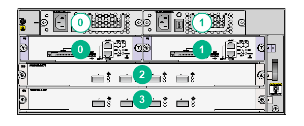
Figure 2 Slot arrangement on the SR8803-X-S router
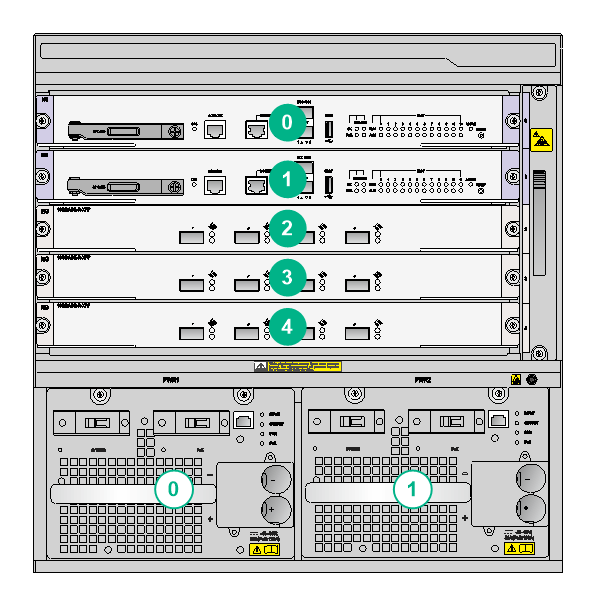
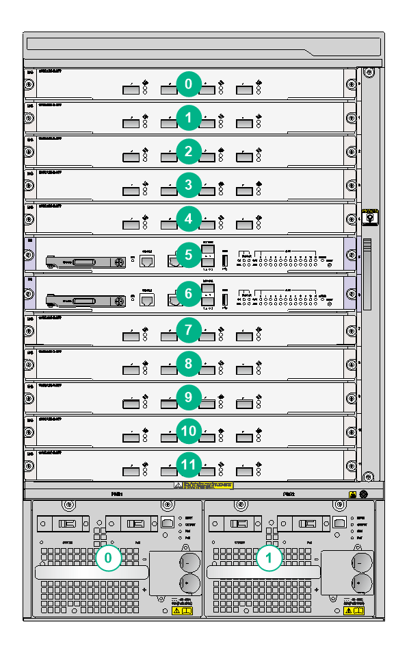
Figure 3 Slot arrangement on the SR8810-X-S router
Card slot arrangement
Table 1 Card slot arrangement
|
MPU installation location |
Model |
Card slot numbering |
Card slot arrangement |
|
Uppermost card slots on the front panel |
SR8802-X-S |
As shown in Figure 1, the card slots are numbered 0 to 3 from left to right and top to bottom. |
· MPU slots: slots 0 and 1 · Service module slots: slots 2 and 3 |
|
Two uppermost card slots on the front panel |
SR8803-X-S |
As shown in Figure 2, the card slots are numbered 0 to 4 from top to bottom. |
· MPU slots: slots 0 and 1 · Service module slots: slots 2 to 4 |
|
SR8806-X-S |
The card slots are numbered 0 to 7 from top to bottom |
· MPU slots: slots 0 and 1 · Service module slots: slots 2 to 7 |
|
|
Two middle card slots on the front panel |
SR8810-X-S |
As shown in Figure 3, the card slots are numbered 0 to 11 from top to bottom. |
· MPU slots: slots 5 and 6 · Service module slots: slots 0 to 4 and slots 7 to 11 |
Subcard slot arrangement and port numbering
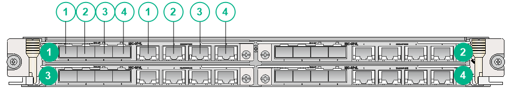
The subcard slots and ports on a subcard follow the same numbering sequence: from left to right and top to bottom.
As shown in Figure 4, two MIC-GP4L subcards are installed on a CSPEX-1504X base card. The numbers in the green circles are subslot numbers. The numbers in the white circles are port numbers. The fiber and copper ports of a combo interface are numbered the same.
Figure 4 Subcard slot arrangement and port numbering
Power supply slot arrangement
As shown in Figure 1, Figure 2, Figure 3, the power supply slots are numbered 0 and 1 from left to right.
Port numbering
Conventions
The router provides multiple types of ports, including console port, USB console port, GE port, XGE port, network management port, and POS port.
When the router is in standalone mode, the ports are numbered in the interface-type slot/subslot/num format. When the router is in IRF mode, the ports are numbered in the interface-type chassis/slot/subslot/num format.
Where,
· interface-type—Port type, GE port and POS port for example.
· chassis—IRF member ID of the router. For information about IRF member IDs, see H3C SR8800-X Router Series Virtual Technologies Configuration Guide.
· slot—Number of the slot where the card resides, as shown by the number in the green circles in Figure 1, Figure 2, and Figure 3.
· subslot—Number of the slot where the subcard resides on the SPEX/CSPEX/MPE base card, as shown by the number in the green circles in Figure 4.
For the SPC/CSPC/OAA card, the subcard slot number is 0.
· num—Number of the port on an SPC/CSPC/OAA card or a subcard, as shown by the number in the white circles in Figure 4.
For each port type on an SPC/CSPC/OAA card or a subcard, the number num starts from 1.
The slot number, subslot number, and port number of the network management port on an MPU are all 0.
|
|
IMPORTANT: · Different subcards on the same SPEX/CSPEX/MPE base card have the same slot number. · Different interfaces on the same subcard have the same subslot number. |
Example
Example 1
Two SR07MPUA1 MPUs are installed in the SR8802-X-S router.
The network management port on the MPU is numbered M-GigabitEthernet 0/0/0.
Example 2
A MIC-GP4L subcard is installed on a CSPEX-1504X base card in slot 3 of the router.
· If the MIC-GP4L subcard is installed in subslot 1 of the CSPEX-1504X base card, the GE ports 1 to 4 on the MIC-GP4L subcard are numbered GigabitEthernet 3/1/1 to GigabitEthernet 3/1/4, respectively.
· If the MIC-GP4L subcard is installed in subslot 2 of the CSPEX-1504X base card, the GE ports 1 to 4 on the MIC-GP4L subcard are numbered GigabitEthernet 3/2/1 to GigabitEthernet 3/2/4, respectively.
· If the MIC-GP4L subcard is installed in subslot 3 of the CSPEX-1504X base card, the GE ports 1 to 4 on the MIC-GP4L subcard are numbered GigabitEthernet 3/3/1 to GigabitEthernet 3/3/4, respectively.
· If the MIC-GP4L subcard is installed in subslot 4 of the CSPEX-1504X base card, the GE ports 1 to 4 on the MIC-GP4L subcard are numbered GigabitEthernet 3/4/1 to GigabitEthernet 3/4/4, respectively.
Example 3
An SPC-GP48LB card is installed in slot 3 of the router. Ports 1 to 48 on the card are numbered GigabitEthernet 3/0/1 to GigabitEthernet 3/0/48, respectively.
