- Table of Contents
-
- H3C SR8800-X-S Router Series Installation Guide-5W103
- 00-Preface
- 01-Chapter 1 Preparing for Installation
- 02-Chapter 2 Installing the Router
- 03-Chapter 3 Installing FRUs
- 04-Chapter 4 Connecting Your Router to the Network
- 05-Chapter 5 Troubleshooting
- 06-Chapter 6 Replacement Procedures
- 07-Appendix A Chassis Views and Technical Specifications
- 08-Appendix B FRUs and Compatibility Matrixes
- 09-Appendix C LEDs
- 10-Appendix D Slot arrangement and port numbering
- 11-Appendix E Cables
- 12-Appendix F Cable Management
- 13-Appendix G Engineering Labels for Cables
- Related Documents
-
| Title | Size | Download |
|---|---|---|
| 09-Appendix C LEDs | 399.96 KB |
PSR320-A/PSR650-A/PSR650-D/PSR1200-A/PSR1200-D power supply LED
PSR1400-A/PSR2500-12AHD/PSR2500-12D power supply LEDs
Appendix C LEDs
The SR8800-X-S routers provide LEDs for you to check the status of MPUs, service modules, and power supplies. The type and quantity of LEDs vary by MPU and service module models.
|
LEDs at a glance |
|
MPU LEDs: |
|
Service module LEDs: |
|
Power supply LEDs: · PSR320-A/PSR650-A/PSR650-D/PSR1200-A/PSR1200-D power supply LED |
MPU LEDs
Unless otherwise stated, the flashing frequency of the LEDs in this section is 0.5 Hz.
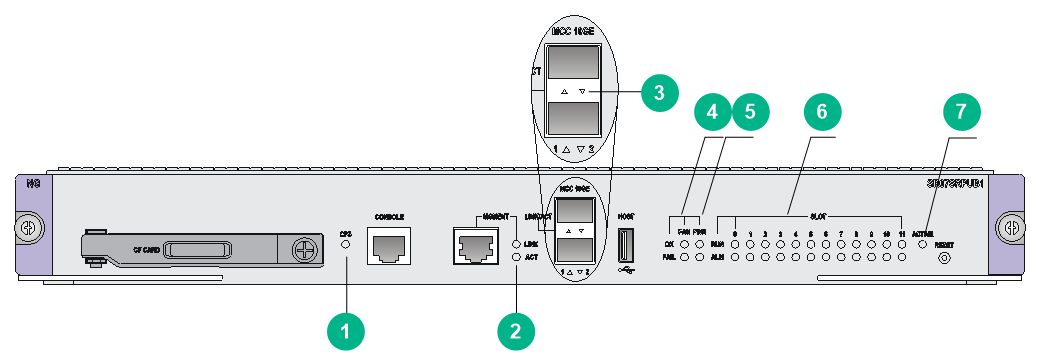
Figure 1 LEDs on the SR07SRPUB1
|
(1) CF card status LED (CFS) |
(2) Management Ethernet port LEDs |
|
(3) 10-GE MCC port LEDs |
(4) Fan tray status LEDs |
|
(5) Power status LEDs |
(6) Card status LEDs |
|
(7) MPU active/standby status LED |
|
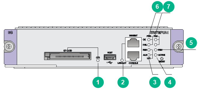
Figure 2 LEDs on the SR07MPUA1
|
(1) CF card status LED (CFS) |
(2) Management Ethernet port LED |
|
(3) Service module (LPU) status LEDs |
(4) MPU active/standby status LED |
|
(5) MPU status LED |
(6) Power status LEDs |
|
(7) Fan tray status LEDs |
|
Table 1 Description for the LEDs on the MPU
|
LED |
Description |
|
CF card status LED |
See Table 2. |
|
Management Ethernet port LED |
· For SR07SRPUA1, SR07SRPUB1, SR07SRPUC1, and SR07SRPUD3, see Table 3. · For SR07MPUA1 and SR07MPUA3, see Table 4. |
|
10-GE MCC port LED |
See Table 5. |
|
Power status LED |
· For SR07SRPUB1, SR07SRPUC1, SR07MPUA1, and SR07SRPUD3, see Table 6. · For SR07SRPUA1 and SR07MPUA3, see Table 7. |
|
Fan tray status LED |
· For SR07SRPUB1, SR07SRPUC1, SR07MPUA1, and SR07SRPUD3, see Table 8. · For SR07SRPUA1 and SR07MPUA3, see Table 9. |
|
Card status LED |
· For SR07SRPUA1, see Table 10. · For SR07SRPUB1, SR07SRPUC1, and SR07SRPUD3, see Table 11. · For SR07MPUA1 and SR07MPUA3, see Table 12 for the MPU status LED and Table 13 for service module status LEDs. |
|
MPU active/standby status LED |
See Table 14. |
CF card status LED
Table 2 CF card status LED description
|
Status |
Description |
|
Steady on |
The CF card is present. |
|
Off |
The CF card is not present or faulty. |
Management Ethernet port LEDs
Table 3 Management Ethernet port LED description (1)
|
LINK LED status |
ACT LED status |
Description |
|
Steady on |
Flashing |
The network management port is sending or receiving data. |
|
Steady on |
Off |
A link is present. |
|
Off |
Off |
No link is present. |
Table 4 Management Ethernet port LED description (2)
|
Status |
Description |
|
Flashing |
The network management port is sending or receiving data. |
|
Steady on |
A link is present. |
|
Off |
No link is present. |
10-GE MCC port LEDs
Table 5 10-GE MCC port LED description
|
Status |
Description |
|
Flashing |
The port is sending or receiving data. |
|
Steady on |
A link is present. |
|
Off |
No link is present. |
Power status LEDs
Table 6 Power status LED description (OK and FAIL)
|
OK LED status |
FAIL LED status |
Description |
|
Steady on |
Off |
All power supplies are operating correctly. |
|
Off |
Steady on |
A power supply is not outputting power because one of the following condition exists: · The module is faulty or switched off. · The power cord is disconnected. · The power supply is switched off. |
|
Off |
Off |
· No power supply is installed. · No power supply is outputting power because one of the following condition exists: ¡ The module is faulty or switched off. ¡ The power cord is disconnected. ¡ The power supply is switched off. |
Table 7 Power status LED description (OK/FAIL)
|
Status |
Description |
|
Steady green |
All power supplies are operating correctly. |
|
Steady red |
A power supply is not outputting power because one of the following condition exists: · The module is faulty or switched off. · The power cord is disconnected. · The power supply is switched off. |
|
Off |
· No power supply is installed. · No power supply is outputting power because one of the following condition exists: ¡ The module is faulty or switched off. ¡ The power cord is disconnected. ¡ The power supply is switched off. |
Fan tray status LEDs
Table 8 Fan tray status LED description (1)
|
OK LED status |
FAIL LED status |
Description |
|
Steady green |
Off |
The fan tray is operating correctly. |
|
Off |
Steady red |
A fan problem is present or the fan tray is not present. |
|
Off |
Off |
The router is not powered on. |
Table 9 Fan tray status LED description (2)
|
Status |
Description |
|
Steady green |
The fan tray is operating correctly. |
|
Steady red |
A fan problem has occurred or the fan tray is not present. |
|
Off |
The router is not powered on. |
Card status LEDs
Before the active MPU starts up, all card LEDs are off. The following tables describe the card LED status after the active MPU starts up.
When the system starts up, the ALM LEDs for all present cards might light for a period of time before the system operates correctly.
Table 10 Card status LED description (SR07SRPUA1)
|
Status |
Description |
|
Flashing green |
The card is operating correctly. |
|
Flashing green (4 Hz) |
The service module is loading software. If the LED flashes continuously, the software version of the router does not match that of the card. |
|
Steady red |
The card is starting up or faulty. |
|
Flashing red |
The temperature of the card has exceeded the upper limit or dropped below the lower limit. |
|
Off |
No card is present. |
Table 11 Card status LED description (SR07SRPUB1/SR07SRPUC1/SR07SRPUD3)
|
RUN LED status |
ALM LED status |
Description |
|
Flashing |
Off |
The card is operating correctly. |
|
Fast flashing (4 Hz) |
Steady on |
The service module is loading software. If the LED flashes continuously, the software version of the router does not match that of the card. |
|
Flashing |
Slow flashing (0.25 Hz) |
The temperature of the card has exceeded the upper limit or dropped below the lower limit. |
|
Steady on |
Steady on |
The card is starting up or faulty. |
|
Off |
Off |
No card is present. |
Table 12 MPU status LED description (SR07MPUA1/SR07MPUA3)
|
Status |
Description |
|
Flashing |
The card is operating correctly. |
|
Off |
The card is starting up or faulty. |
Table 13 Service module status LED description (SR07MPUA1/SR07MPUA3)
|
RUN LED status |
ALM LED status |
Description |
|
Flashing |
Off |
At least one card is operating correctly. |
|
Fast flashing |
Steady on |
At least one card is loading software. If the LED flashes continuously, the software version of the router does not match that of the card. |
|
Steady on |
Steady on |
At least one card is starting up or faulty. |
|
Off |
Off |
No card is present. |
MPU active/standby status LED
Table 14 MPU active/standby status LED description
|
Status |
Description |
|
Steady on |
The MPU is operating in active mode. |
|
Off |
· The MPU is operating in standby mode. · The MPU is faulty. Examine also the status LED for the MPU to determine whether a fault has occurred. |
Service module LEDs
SPC/CSPC card LEDs
RJ-45 Ethernet port LEDs
Table 15 RJ-45 Ethernet port LED description
|
Status |
Description |
|
Flashing |
The port is receiving or sending data. |
|
Steady on |
A link is present. |
|
Off |
No link is present. |
SFP port LEDs
Table 16 SFP port LED description
|
Status |
Description |
|
Flashing |
The port is receiving or sending data. |
|
Steady on |
A link is present. |
|
Off |
No link is present. |
SFP+ port LEDs
Table 17 SFP+ port LED description
|
Status |
Description |
|
Flashing |
The port is receiving or sending data. |
|
Steady on |
A link is present. |
|
Off |
No link is present. |
XFP port LEDs
Table 18 XFP port LED description
|
LINK LED status |
ACT LED status |
Description |
|
Steady on |
Flashing |
The port is receiving or sending data. |
|
Steady on |
Off |
A link is present. |
|
Off |
Off |
No link is present. |
QSFP+ port LEDs
Table 19 QSFP+ port LED description
|
Status |
Description |
|
Flashing |
The port is receiving or sending data. |
|
Steady on |
A link is present. |
|
Off |
No link is present. |
CFP port LEDs
Table 20 CFP port LED description
|
Status |
Description |
|
Flashing |
The port is receiving or sending data. |
|
Steady on |
A link is present. |
|
Off |
No link is present. |
SPEX/CSPEX/MPE card LED
Table 21 SPEX/CSPEX/MPE card LED description
|
LED mark |
Status |
Description |
|
RUN |
Steady green |
The card is faulty. |
|
Off |
The card is faulty or not present. |
|
|
Flashing green (about once per second) |
The card is operating correctly. |
|
|
Fast flashing green (about eight times per second) |
The card is starting up. If the LED keeps fast flashing, the card has failed registration. |
Subcard LEDs
PIC subcard LEDs
Table 22 PIC subcard LEDs
|
LEDs |
PIC subcard |
Description |
|
GE SFP port LED |
· PIC-GP10L · PIC-PS2G4L |
See Table 23. |
|
10-GE XFP port LED |
PIC-XP1L |
See Table 24. |
|
WAN port LED |
· PIC-TCP8L · PIC-PSP4L · PIC-PUP1L · PIC-PS2G4L |
See Table 25. |
Table 23 GE SFP port LED description
|
LED |
Status |
Description |
|
LINK/ACT |
Flashing green |
The port is sending or receiving data. |
|
Steady green |
A link is present. |
|
|
Off |
No link is present. |
Table 24 10-GE XFP port LED description
|
LED |
Status |
Description |
|
LINK/ACT |
Flashing green |
The port is sending or receiving data. |
|
Steady green |
A link is present. |
|
|
Off |
No link is present. |
Table 25 WAN port LED description
|
LED |
Status |
Description |
|
ACT/ALM |
Steady green |
A link is present. |
|
Steady red |
An alarm has occurred. |
|
|
Off |
No link is present. |
MIC subcard LEDs
Table 26 MIC subcard LEDs
|
LEDs |
PIC subcard |
Description |
|
RJ-45 port status LED |
MIC-GT20L. |
See Table 15. |
|
SFP+ port status LED |
MIC-XP5L MIC-XP2L MIC-XP2L-LAN MIC-XP4L1 MIC-XP5L1 MIC-XP8L |
See Table 17. |
|
CFP port status LED |
MIC-CP1L |
See Table 20. |
|
Combo interface status LED |
MIC-GP4L |
See Table 27. |
|
GE SFP port status LED |
MIC-GP8L MIC-GP10L1 MIC-GP10L-V2 MIC-GP20L MIC-GP20L1 |
See Table 28. |
|
WAN port status LED |
MIC-SP4L MIC-SP8L MIC-ET16L MIC-CLP2L MIC-CLP4L |
See Table 31. |
|
QSFP+ port status LED |
MIC-QP1L |
See Table 29. |
|
QSFP28 port status LED |
MIC-CQ1L1 |
See Table 30. |
|
WAN port status LED |
MIC-SP4L MIC-SP8L MIC-ET16L MIC-CLP2L MIC-CLP4L MIC-PSP4L MIC-TCP8L |
See Table 31. |
Table 27 Combo interface LED description
|
LED |
Status |
Description |
|
Combo fiber port |
||
|
LINK/ACT |
Steady green |
A link is present. |
|
Flashing green |
The port is sending or receiving data. |
|
|
Off |
No link is present. |
|
|
Combo copper port |
||
|
LINK |
Steady green |
A link is present. |
|
Off |
No link is present. |
|
|
ACT |
Flashing amber |
The port is sending or receiving data. |
|
Off |
The port is not sending or receiving data. |
|
Table 28 GE SFP port LED description
|
LED |
Status |
Description |
|
LINK/ACT |
Flashing green |
The port is sending or receiving data. |
|
Steady green |
A link is present. |
|
|
Off |
No link is present. |
Table 29 QSFP+ port LED description
|
Status |
Description |
|
Flashing |
The port is receiving or sending data. |
|
Steady on |
A link is present. |
|
Off |
No link is present. |
Table 30 QSFP28 port LED description
|
Status |
Description |
|
Flashing |
The port is receiving or sending data. |
|
Steady on |
A link is present. |
|
Off |
No link is present. |
Table 31 WAN port LED description
|
LED |
Status |
Description |
|
ACT/ALM |
Flashing green |
The port is sending or receiving data. |
|
Steady green |
A link is present. |
|
|
Steady red |
An alarm has occurred. |
|
|
Off |
No link is present. |
OAA module LEDs
The OAA module provides LEDs to show the operating status of the module and ports.
Table 32 LED description
|
Status |
Description |
|
ALM |
|
|
Off |
The system is operating correctly. |
|
Steady red |
A serious failure has occurred. You must read the system log for troubleshooting immediately. |
|
RUN |
|
|
Off |
No power is being input or the card is faulty. |
|
Steady green |
The system is not operating correctly. |
|
Flashing green (1 Hz) |
The system has started up and is operating correctly. |
|
Fast flashing green (8 Hz) |
The system is loading software or is not operating. |
|
LINK/ACT (for the combo interface) |
|
|
Off |
No link is present on the port. |
|
Steady green |
A link is present on the port. |
|
Flashing green |
The port is sending or receiving data. |
Power supply LEDs
PSR320-A/PSR650-A/PSR650-D/PSR1200-A/PSR1200-D power supply LED
Table 33 PSR320-A/PSR650-A/PSR650-D/PSR1200-A/PSR1200-D power supply LED description
|
Status |
Description |
Analysis |
|
Steady green |
The power supply is operating correctly. |
N/A |
|
Steady red |
The power supply is operating incorrectly. |
This status occurs when any of the following conditions exists: · The power supply generates an alarm and enters the protection state due to: ¡ Input under-voltage ¡ Output short-circuit, over-current, or over-voltage ¡ Over temperature · A fan failure has occurred. |
|
Off |
The power input is incorrect. |
This status occurs when any of the following conditions exists: · The power supply is faulty. · A power cord connection failure has occurred. · The external power supply is unavailable. · The power supply is not switched on. |
PSR1400-A/PSR2500-12AHD/PSR2500-12D power supply LEDs
Table 34 PSR1400-A/PSR2500-12AHD/PSR2500-12D power supply LED description
|
Status |
Description |
Analysis |
|
INPUT |
||
|
Green |
The power is input correctly. |
N/A |
|
Red |
The power input is incorrect. |
The input voltage is not in the rated voltage range. |
|
Off |
No power is input. |
This status occurs when any of the following conditions exists: · The power supply is faulty. · A power cord connection failure has occurred. · The external power supply is unavailable. |
|
OUTPUT |
||
|
Green |
The power is output correctly. |
N/A |
|
Red |
A power output problem has occurred. |
This status occurs when any of the following conditions exists: · The power supply generates an alarm and enters the protection state due to: ¡ Input under-voltage ¡ Output short-circuit, over-current, or over-voltage ¡ Over temperature · The power supply is not switched on. |
|
Off |
No power is output. |
This status occurs when any of the following conditions exists: · The power supply is faulty. · A power cord connection failure has occurred. · The external power supply is unavailable. |
|
FAN |
||
|
Green |
The fans are operating correctly. |
N/A |
|
Red |
The fans are operating incorrect. |
This status occurs when any of the following conditions exists: · A fan failure has occurred. · The power supply is not switched on. |
|
Off |
The fans do not operate. |
This status occurs when any one of the following conditions exists: · The power supply is faulty. · A power cord connection failure has occurred. · The external power supply is unavailable. |
PSR1400-D power supply LEDs
Table 35 PSR1400-D power supply LED description
|
Status |
Description |
Analysis |
|
INPUT |
||
|
Green |
The power is input correctly, and the system power output switch is turned on. |
N/A |
|
Red |
The power input is incorrect. |
The input voltage is not in the rated voltage range. |
|
Off |
No power is input. |
This status occurs when any of the following conditions exists: · The power supply is faulty. · A power cord connection failure has occurred. · The external power supply is unavailable. · The system power output switch is not turned on. |
|
OUTPUT |
||
|
Green |
The power is output correctly. |
N/A |
|
Red |
The power output is incorrect. |
The power supply generates an alarm and enters the protection state due to: · output short-circuit, over-current, or over-voltage · over temperature |
|
Off |
No power is output. |
This status occurs when any of the following conditions exists: · The power supply is faulty. · A power cord connection failure has occurred. · The external power supply is unavailable. · The system power output switch is not turned on. |
|
FAN |
||
|
Green |
The fans are operating correctly. |
N/A |
|
Red |
The fans are operating incorrectly. |
A fan failure has occurred. |
|
Off |
The fans do not operate. |
This status occurs when any of the following conditions exists: · The power supply is faulty. · A power cord connection failure has occurred. · The external power supply is unavailable. · The system power output switch is not turned on. |
