- Table of Contents
- Related Documents
-
| Title | Size | Download |
|---|---|---|
| 01-Text | 3.63 MB |
Plan the IP address assignment scheme
About network port virtualization
Prerequisites: Configure IP address settings for the network port connected to the mge_bridge bridge
Configure the MTU of a Linux bridge network port
Configure the management network
Deploy the simulation service on the controller
Preconfigure the simulation network
Enabling the design mode for the tenant
Configure tenant service simulation
Evaluate the simulation and view the simulation result
Deploy configuration and view deployment details
Introduction
In the DC scenario, the SeerEngine-DC services are complicated, and hard to operate. After complicated operations, you might fail to achieve the expected results. As a result, a large number of human and material resources are wasted. Therefore, it is necessary to perform a rehearsal before deploying actual services. During the rehearsal process, you can learn and avoid risks, so that you can reduce the risk possibilities for the production environment to the maximum extent. The simulation function is introduced for this purpose. The simulation function simulates a service and estimates resource consumption before you deploy the service. It helps users to determine whether the current service orchestration can achieve the expected effect and affect existing services, and estimate the device resources to be used.
The simulation function provides the following features:
· Simulation network—The simulation network model is built in a 1:1 ratio to the real network through vSwitches. The simulation system is built based on the simulation network model, which needs highly automated management.
· Tenant service simulation—This function mainly orchestrates and configures the tenant service of the logical network. This function simulates a service and estimates resource consumption before you deploy the service. It helps users to determine whether the current service orchestration can achieve the expected effect and affect existing services. This function includes capacity simulation, connectivity simulation, and network-wide impact analysis. You can deploy the service configuration to real devices when the simulation evaluation result is as expected.
· Simulation records—Displays the simulation records of users and provides the advanced search function.
This document describes how to deploy the DTN hosts and dependencies and build a simulation network on the controller.
Environment setup workflow
Table 1 shows the workflow to set up a simulation environment.
Table 1 Environment deployment workflow
|
Step |
Tasks |
|
Deploy the Unified Platform |
See H3C Unified Platform Deployment Guide. |
|
Deploy the SeerEngine-DC and DTN components |
See H3C SeerEngine-DC Installation Guide (Unified Platform). |
Plan the network
Plan network topology
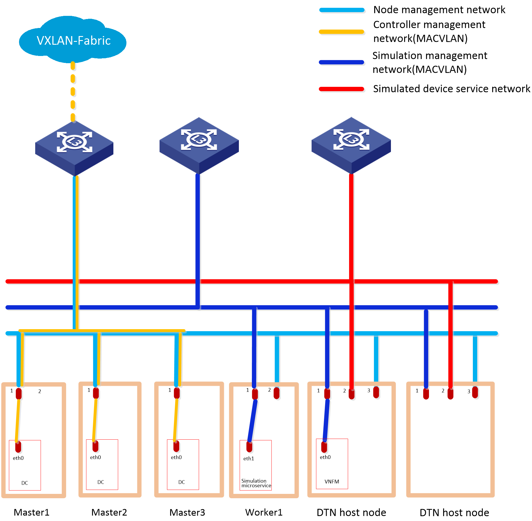
A simulation network includes four types of networks, including node management network, controller management network, simulation management network, and simulated device service network.
· Node management network—Network over which you can log in to servers to perform routine maintenance.
· Controller management network—Network for cluster communication between controllers and device management.
· Simulation management network—Network over which the digital twin network (DTN) microservice component and DTN hosts exchange management information.
· Simulated device service network—Network over which the DTN hosts exchange service data.
Before you deploy the simulation system, plan the simulation management network and simulated device service network.
Figure 1 Typical simulation network topology design for the Cloud DC scenario in non-remote disaster recovery mode
|
|
CAUTION: · If the controller management network and simulation management network use the same management switch, configure VLANs for isolation on the management switch to isolate the simulation network from the production network. If the controller management network uses the Layer 3 networking mode, you must also configure VPN instances for isolation on the management switch to prevent IP address conflicts from affecting the services. If the controller management network and simulation management network use different management switches, physically isolate these switches. · Configure routes to provide Layer 3 connectivity between simulation management IPs and simulated device management IPs. · The simulated device service network of the DTN hosts needs to be reachable at Layer 2. |
Plan the IP address assignment scheme
As a best practice, use Table 2 to calculate the minimum number of IP addresses on subnets in each network for deployment of a SeerEngine-DC controller cluster and DTN Manager.
Table 2 Number of addresses in subnet IP address pools
|
Component/Node name |
Network name (type) |
Max number of cluster members |
Default number of cluster members |
Calculation method |
Remarks |
|
SeerEngine-DC |
Controller management network (MACVLAN) |
32 |
3 |
1 x cluster member count + 1 (cluster IP) |
N/A |
|
DTN component |
Simulation management network (MACVLAN) |
1 |
1 |
Single node deployment, which requires only one IP. |
Used by the simulation microservice deployed on the controller node |
|
DTN host |
Simulation management network |
2×the number of DTN hosts |
2×the number of DTN hosts |
2×the number of DTN hosts |
Used by DTN hosts |
This document uses the IP address plan in Table 3 for example.
Table 3 IP address plan example
|
Component/node name |
Network name (type) |
IP address |
|
SeerEngine-DC |
Controller management network (MACVLAN) |
Subnet: 192.168.12.0/24 (gateway address: 192.168.12.1) |
|
Network address pool: 192.168.12.101/24 to 192.168.12.132/24 |
||
|
DTN component |
Simulation management network (MACVLAN) |
Subnet: 192.168.12.0/24 (gateway address: 192.168.12.1) |
|
Network address pool: 192.168.12.133/24 to 192.168.12.133/24 |
||
|
DTN host |
Simulation management network |
Network address pool: 192.168.12.134/24 to 192.168.12.144/24 |
|
Node management network |
Network address pool: 192.168.10.110/24 to 192.168.10.120/24 |
|
|
IMPORTANT: The node management network and simulation management network of a DTN host must be on different network segments. |
Deploy DTN hosts
Server requirements
Hardware requirements
Table 4 shows the hardware requirements for simulation hosts. Select a hardware configuration option depending on the number of simulated devices that you need to manage.
|
Max simulated devices |
CPU architecture |
CPU cores and frequency |
Memory |
Total system disk space |
Min NIC configuration |
|
80 |
VT-X/VT-D x86-64 (Intel64/AMD64) architecture |
20 cores @ 2.2 GHz (or higher) |
256 GB (or higher) |
Select either of the following disk options: · 2*960GB SSD+RAID1 or 4*480GB SSD+RAID10 (600 GB or higher after RAID setup) · 2*600 GB HDD+RAID1 (600 GB or higher after RAID setup), 7.2K RPM or higher |
3 x 1 Gbps or 10 Gbps NICs |
|
30 |
VT-X/VT-D x86-64 (Intel64/AMD64) architecture |
16 cores @ 2.0 GHz (or higher) |
128 GB (or higher) |
Select either of the following disk options: · 2*960GB SSD+RAID1 or 4*480GB SSD+RAID10 (600 GB or higher after RAID setup) · 2*600 GB HDD+RAID1 (600 GB or higher after RAID setup), 7.2K RPM or higher |
3 x 1 Gbps or 10 Gbps NICs |
|
|
NOTE: As a best practice, enable the hyper-threading feature (if available) of the CPU. |
Software requirements
The simulation hosts must install an operating system that meets the requirements in Table 5.
Table 5 Operating systems and versions supported by the host
|
OS name |
Version number |
Kernel version |
|
H3Linux |
V1.3.1 |
5.10 |
Install the operating system
|
|
CAUTION: Before you install H3Linux on a server, back up server data. H3Linux will replace the original OS (if any) on the server with data removed. |
The H3Linux_K510_version.iso (where version is the version number) image is the H3Linux operating system installation package. The following information uses a server without an OS installed for example to describe the installation procedure of the H3Linux_K510_version.iso image.
1. Obtain the required H3Linux_K510_version.iso image in ISO format.
2. Access the remote console of the server, and then mount the ISO image as a virtual optical drive.
3. Configure the server to boot from the virtual optical drive, and then restart the sever.
After the ISO image is loaded, the INSTALLATION SUMMARY page opens.
Figure 2 INSTALLATION SUMMARY page
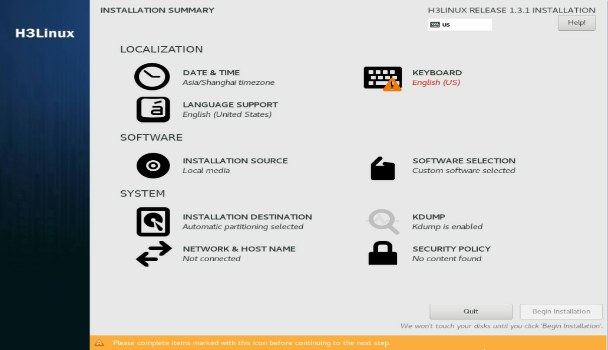
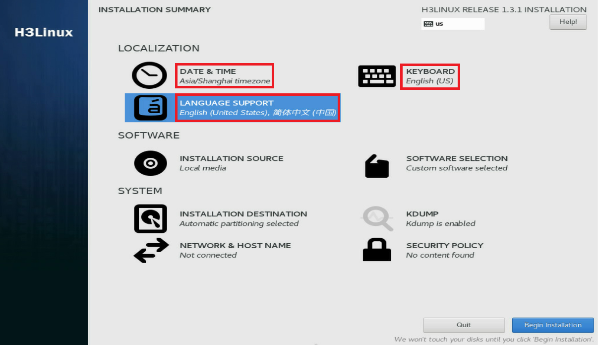
4. In the LOCALIZATION area, perform the following steps:
¡ Click DATE & TIME to modify the date and time settings.
¡ Click KEYBOARD to modify keyboard settings as needed.
¡ Click LANGUAGE SUPPORT to select your preferred language.
|
|
IMPORTANT: Make sure you select the same time zone across the hosts. In this document, [Asia/Shanghai] is selected for example. |
Figure 3 INSTALLATION SUMMARY page
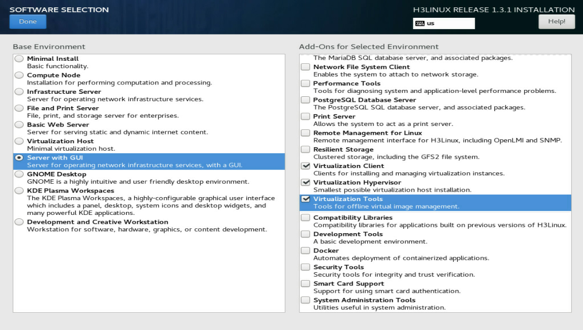
5. Click SOFTWARE SELECTION in the SOFTWARE area to enter the page for selecting software. Select the Server with GUI base environment and the File and Storage Server, Virtualization Client, Virtualization Hypervisor, and Virtualization Tools add-ons. Then, click Done to return to the INSTALLATION SUMMARY page.
Figure 4 SOFTWARE SELECTION page (1)
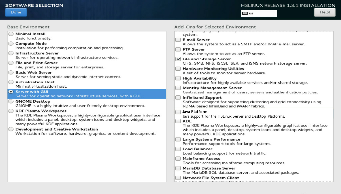
Figure 5 SOFTWARE SELECTION page (2)
6. In the SYSTEM area, click INSTALLATION DESTINATION.
Figure 6 INSTALLATION DESTINATION dialog box
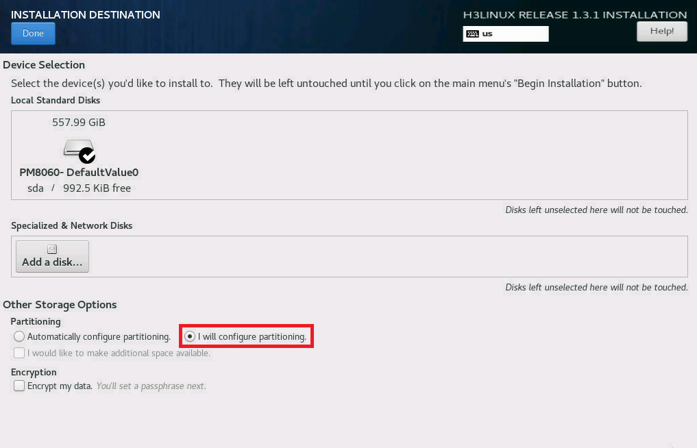
7. In the dialog box that opens, perform the following operations:
a. Select a local disk from the Local Standard Disks area.
b. In the Other Storage Options area, select I will configure partitioning.
c. Click Done.
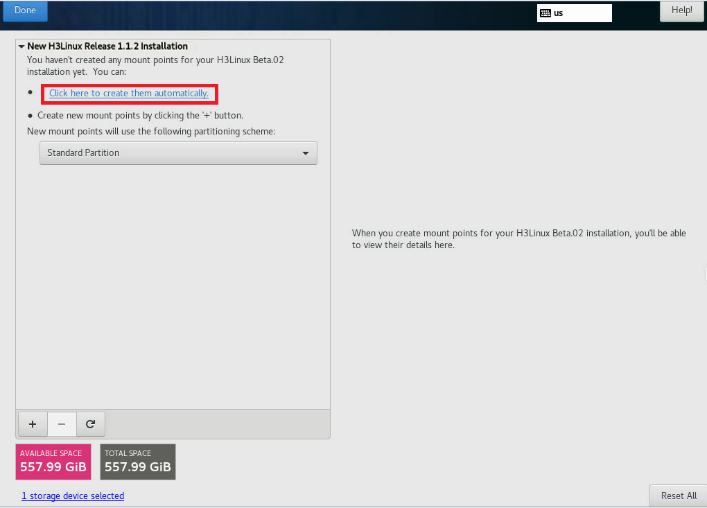
8. In the MANUAL PARTITIONING dialog box, click Click here to create them automatically to automatically generate recommended partitions.
Figure 7 MANUAL PARTITIONING dialog box
The list of automatically created partitions opens. Figure 8 shows the list of automatically created partitions when the disk size is 600 GiB.
|
|
IMPORTANT: The /boot/efi partition is available only if UEFI mode is enabled for OS installation. |
Figure 8 Automatically created partition list
9. Set the device type and file system of a partition. As a best practice, set the device type to Standard Partition to improve system stability. Table 6 shows the device type and file system of each partition used in this document.
|
Partition name |
Device type |
File system |
|
/boot |
Standard Partition |
xfs |
|
/boot/efi (UEFI mode) |
Standard Partition |
EFI System Partition |
|
/ |
Standard Partition |
xfs |
|
/swap |
Standard Partition |
swap |
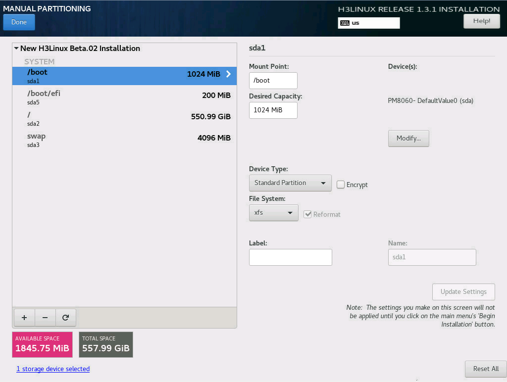
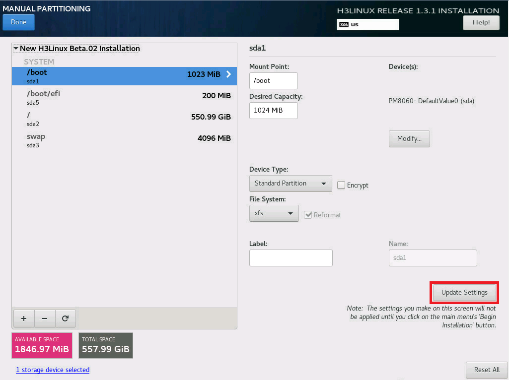
10. Edit the device type and file system of a partition as shown in Figure 9. Take the /boot partition for example. Select a partition on the left, and select Standard Partition from the Device Type list and xfs from the File System list. Then, click Update Settings.
Figure 9 Configuring partitions
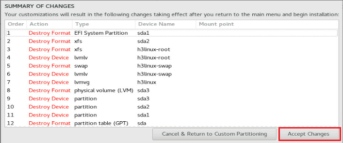
11. After you finish the partitioning task, click Done in the upper left corner. In the dialog box that opens, select Accept Changes.
Figure 10 Accepting changes
12. In the INSTALLATION SUMMARY window that opens, click NETWORK & HOSTNAME in the SYSTEM area to configure the host name and network settings.
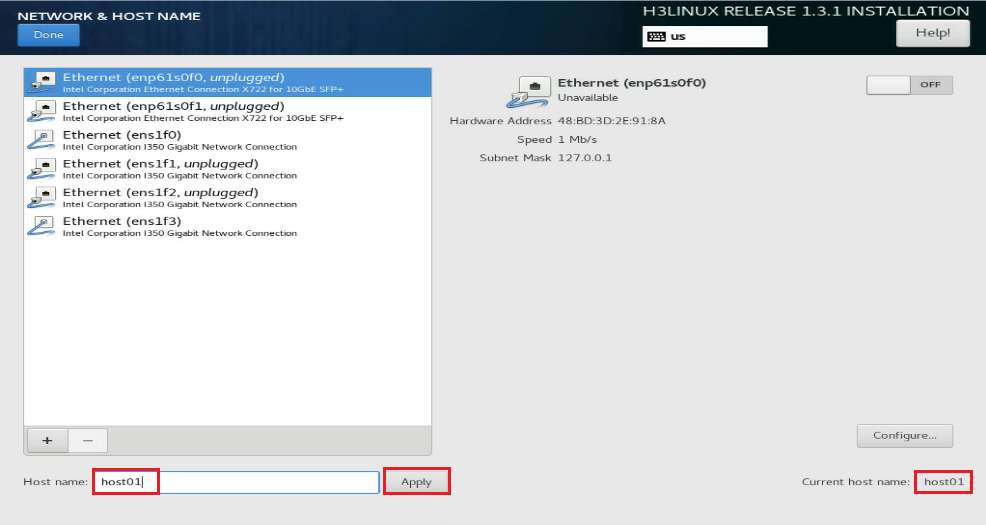
13. In the Host name field, enter the host name for this server, and then click Apply.
Figure 11 Setting the host name
14. Configure the network settings:
|
|
IMPORTANT: Configure network ports as planned. The server requires a minimum of three network ports. · The network port IP for the simulation management network is used for communication with the DTN component. · The network port IP for the simulated device service network does not need to be configured with IP. · The network port IP for the node management network is used for routine maintenance of servers. |
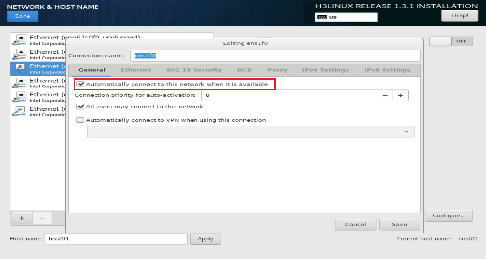
a. Select a network port and then click Configure.
b. In the dialog box that opens, configure basic network port settings on the General tab:
- Select the Automatically connect to this network when it is available option .
- Verify that the All users may connect to this network option is selected. By default, this option is selected.
Figure 12 General settings for a network port
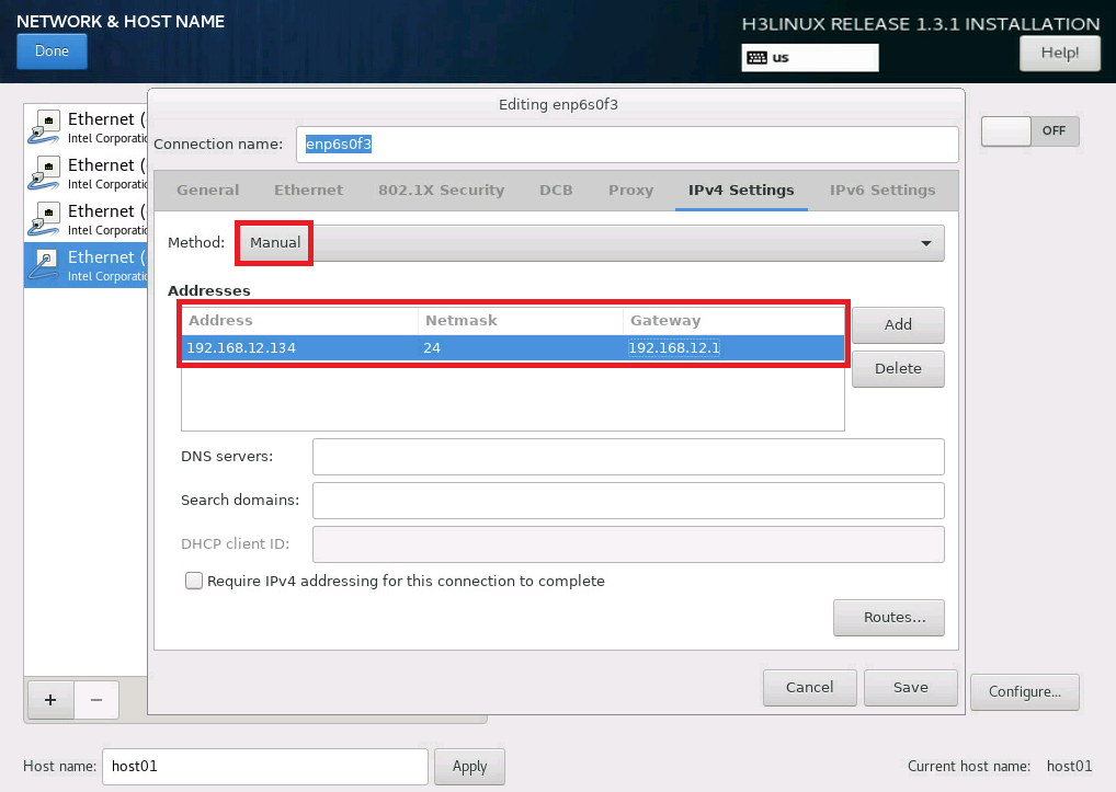
15. Configure IP address settings:
a. Click the IPv4 Settings or IPv6 Settings tab.
b. From the Method list, select Manual.
c. Click Add, assign a simulation management IP address to the DTN host, and then click Save.
d. Click Done in the upper left corner of the dialog box.
|
|
IMPORTANT: DTN service supports IPv4 and IPv6. In the current software version, only a single stack is supported. |
Figure 13 Configuring IPv4 address settings for a network port
16. Repeat Step 14 and Step 15 to configure the management IP addresses for DTN hosts. The IP addresses must be in the network address pool containing IP addresses 192.168.10.110 to 192.168.10.120, for example, 192.168.10.110.
17. Click Begin Installation to install the OS.
18. During the installation, configure the root password as prompted:
|
|
IMPORTANT: You must configure a root password before you can continue with the installation. |
a. In the USER SETTINGS area, click ROOT PASSWORD.
b. In the dialog box that opens, set the root password for the system, and then click Done in the upper left corner.
Figure 14 Configuration window for H3Linux OS installation
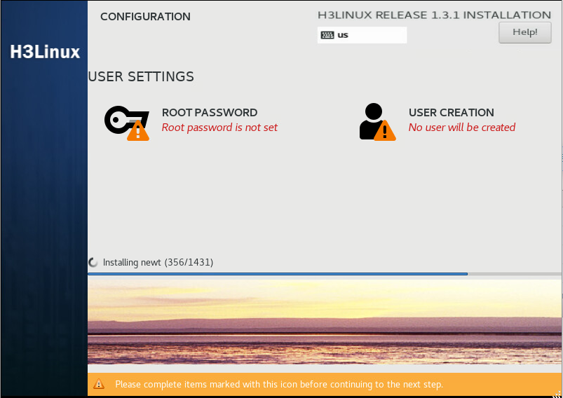
Figure 15 Setting the root password
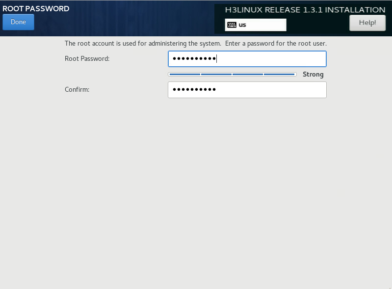
Then, the system automatically reboots to finish OS installation.
Virtualize network ports
|
|
CAUTION: Virtualize network ports on each DTN host. |
About network port virtualization
Each host node must have two network ports: one connected to the simulation management network and one connected to the simulation service network.
On H3Linux, you must create one network bridge for each of them.
· The bridge for the network port connected to the simulation management network is named mge_bridge.
· The bridge for the network port connected to the simulated device service network is named up_bridge.
Prerequisites: Configure IP address settings for the network port connected to the mge_bridge bridge
|
|
IMPORTANT: IP addresses of simulated devices are the same as their twin devices on the product network. To avoid IP conflict, make sure the IP address of a DTN host on the simulation management network is different from the IP address of any simulated device. |
Before you create bridges for the network ports connected to the simulation network, you must assign an IP address to the network port mapped to the mge_bridge bridge. The IP address is used for communication with the DTN microservice component and will be used when you add hosts to the simulation network.
Skip this section if you have assigned an IP address to the network port mapped to the mge_bridge bridge during OS installation, as described in "Install the operating system."
To configure IP address settings for the network port connected to the mge_bridge bridge:
1. Open the /etc/sysconfig/network-scripts/ directory.
[root@host01 ~]# cd /etc/sysconfig/network-scripts/
2. Press I to access the edit mode, configure IP settings, save the configuration, and then exit. This step uses network port ens1f0 for example.
[root@host01 network-scripts]# vi ifcfg-ens1f0
TYPE=Ethernet
PROXY_METHOD=none
BROWSER_ONLY=no
BOOTPROTO=none
DEFROUTE=yes
IPV4_FAILURE_FATAL=no
IPV6INIT=yes
IPV6_AUTOCONF=yes
IPV6_DEFROUTE=yes
IPV6_FAILURE_FATAL=no
IPV6_ADDR_GEN_MODE=stable-privacy
NAME=ens1f0
UUID=2e5b13dc-bd05-4d65-93c7-c0d9228e1b72
DEVICE=ens1f0
ONBOOT=yes
IPADDR=192.168.12.134
PREFIX=24
GATEWAY=192.168.12.1
IPV6_PRIVACY=no
3. Restart the network service.
[root@host01 network-scripts]# service network restart
Install dependency packages
1. Obtain the latest dependency packages, and upload them to the server and compress them. The dependency package format is SeerEngine_DC_DTN_HOST-version.zip, where the version field represents the software version number. In this example, use E6103.
[root@host01 root]# unzip SeerEngine_DC_DTN_HOST-E6103.zip
2. Execute the chmod command to assign permissions to the user.
[root@host01 root]# chmod +x -R SeerEngine_DC_DTN_HOST-E6103
3. Enter the SeerEngine_DC_DTN_HOST-version/ directory of the decompressed dependency package, and execute the ./install.sh command to install the dependency package.
[root@host01 SeerEngine_DC_DTN_HOST-E6103]# ./install.sh
Redirecting to /bin/systemctl restart libvirtd.service
Libvirt configuration succeeded
Install succeeded.
4. Execute the virsh -c qemu+tcp://127.0.0.1:16509/system command to identify whether dependency package is successfully installed. If the following information is output, the installation succeeds. Execute the exit command to exit.
[root@host01]# virsh –c qemu+tcp://127.0.0.1:16509/system
Type: 'help' for help with commands
'quit' to quit
virsh #
Create Linux network bridges
|
|
CAUTION: Execution of the Linux bridge script will cause network service to restart. If you establish an SSH connection to the network port attached to the simulation management or service network, the SSH connection will be interrupted on network service restart. To avoid this situation, establish the SSH connection to the management port of the server. |
1. Access the SeerEngine_DC_DTN_HOST-version/bridge directory after decompression, and then execute the ./bridge-init.sh param1 param2 command to configure the Linux network bridges. The param1 argument represents the name of the network port mapped to the mge_bridge bridge. The param2 argument represents the name of the network port mapped to the up_bridge bridge.
[root@host01 ~]# cd /root/SeerEngine_DC_DTN_HOST-E6103/bridge
[root@host01 bridge]# ./bridge-init.sh ens1f0 ens1f1
network config ens1f0 to bridge mge_bridge complete.
network config ens1f1 to bridge up_bridge complete.
2. Verify that bridges mge_bridge and up_bridge have been successfully created for the network ports.
[root@host01 bridge]# brctl show
bridge name bridge id STP enabled interfaces
mge_bridge 8000.c4346bb8d138 no ens1f0
up_bridge 8000.c4346bb8d139 no ens1f1
virbr0 8000.000000000000 yes
3. Verify that the generated network-scripts configuration file contains the correct configuration. Take network port ens1f0 and bridge mge_bridge for example.
[root@host01 bridge]# cat /etc/sysconfig/network-scripts/ifcfg-mge_bridge
DEVICE=mge_bridge
TYPE=Bridge
BOOTPROTO=static
ONBOOT=yes
IPADDR=192.168.12.134
PREFIX=24
[root@host01 bridge]# cat /etc/sysconfig/network-scripts/ifcfg-ens1f0
DEVICE=ens1f0
HWADDR=c4:34:6b:b8:d1:38
BOOTPROTO=none
ONBOOT=yes
BRIDGE=mge_bridge
[root@host01 bridge]# ifconfig mge_bridge
mge_bridge: flags=4163<UP,BROADCAST,RUNNING,MULTICAST> mtu 1500
inet 192.168.12.134 netmask 255.255.255.0 broadcast 192.168.12.255
inet6 2002:6100:2f4:b:c634:6bff:feb8:d138 prefixlen 64 scopeid 0x0<global>
inet6 fec0::5:c634:6bff:feb8:d138 prefixlen 64 scopeid 0x40<site>
inet6 fec0::b:c634:6bff:feb8:d138 prefixlen 64 scopeid 0x40<site>
inet6 fe80::c634:6bff:feb8:d138 prefixlen 64 scopeid 0x20<link>
inet6 2002:aca8:284d:5:c634:6bff:feb8:d138 prefixlen 64 scopeid 0x0<global>
inet6 2002:6200:101:b:c634:6bff:feb8:d138 prefixlen 64 scopeid 0x0<global>
ether c4:34:6b:b8:d1:38 txqueuelen 0 (Ethernet)
RX packets 29465349 bytes 7849790528 (7.3 GiB)
RX errors 0 dropped 19149249 overruns 0 frame 0
TX packets 4415 bytes 400662 (391.2 KiB)
TX errors 0 dropped 0 overruns 0 carrier 0 collisions 0
4. Identify whether the IP addresses of network ports have been update. Take network port ens1f0 for example.
[root@host01 ~]# ifconfig ens1f0
ens1f0: flags=4163<UP,BROADCAST,RUNNING,MULTICAST> mtu 1500
inet6 fe80::c634:6bff:feb8:d138 prefixlen 64 scopeid 0x20<link>
ether c4:34:6b:b8:d1:38 txqueuelen 1000 (Ethernet)
RX packets 31576735 bytes 8896279718 (8.2 GiB)
RX errors 0 dropped 7960 overruns 0 frame 0
TX packets 4461 bytes 464952 (454.0 KiB)
TX errors 0 dropped 0 overruns 0 carrier 0 collisions 0
device interrupt 16
Table 7 Parameters
|
Parameter |
Description |
|
DEVICE |
Interface name, which must be the same as the name obtained through the ifconfig command. |
|
TYPE |
Interface type. This parameter exists only in the bridge configuration file and must be Bridge. |
|
BOOTPROTO |
Options are none, dhcp, and static. · none—No protocol is used to obtain IP addresses when the network service is enabled. · dhcp—DHCP is used to obtain IP addresses. · static—IP addresses are manually configured. This parameter must be none in a physical interface configuration file and bridge in a bridge configuration file. |
|
ONBOOT |
Options are yes and no. If this field is set to yes, the device is activated when the system starts. If this field is set to no, the device is not activated when the system starts. This parameter is set to yes in this example. |
|
IPADDR |
IP address. The IP address of a physical interface is moved to its bridge, so this parameter does not exist in the physical interface configuration file. In the bridge configuration file, this parameter is the IP address of the original physical interface, which is the same as the IP address obtained by using the ifconfig command. |
|
NETMASK |
Subnet mask of an IP address. For more information, see the IPADDR parameter. |
|
HWADDR |
Interface MAC address. This parameter exists only in physical interface configuration files and must be the same as the value for the ether field in the ifconfig command output. |
|
BRIDGE |
Name of the bridge bound to the physical interface. This parameter exists only in the physical interface configuration files. |
Configure the MTU of a Linux bridge network port
|
|
CAUTION: The setMtu.sh script in the bridge directory can only set MTU for a physical network port. If the specified device is not a physical network port, the system displays "xxx: Device not found." |
By default, the MTU of a physical network port is 1500 bytes. In some network scenarios, you must change this MTU to a higher value to avoid packet drops. For example, you must change the interface MPU if the network has VXLAN traffic. VXLAN adds an extra 8-byte VXLAN header, 8-byte UDP header, and 20-byte IP header to the original Layer 2 frame. To avoid packet drops, you must set the interface MTU to a higher value than the default 1500 bytes.
To set the MTU of a network port and its network bridge:
1. Execute the ./setMtu.sh phyNic mtuSize command.
The phyNic argument represents the physical network port name, and the mtuSize argument represents the MTU value to be set. This example sets the MTU of network port ens1f0 to 1600 bytes.
[root@host01 bridge]# ./setMtu.sh ens1f0 1600
ens1f0 mtu set to 1600 complete.
2. Verify that the MTU has been successfully set.
[root@host01 bridge]# ifconfig ens1f0| grep mtu
ens1f0: flags=4355<UP,BROADCAST,PROMISC,MULTICAST> mtu 1600
[root@host01 bridge]# ifconfig mge_bridge| grep mtu
mge_bridge: flags=4163<UP,BROADCAST,RUNNING,MULTICAST> mtu 1600
[root@host01 bridge]# cat /etc/sysconfig/network-scripts/ifcfg- ens1f0 | grep -i mtu
MTU=1600
Delete Linux bridges
To delete the Linux bridge configuration, execute the ./bridge-rollback.sh param1 param2 command. The param1 argument represents the name of the network port mapped to the mge_bridge bridge. The param2 argument represents the name of the network port mapped to the up_bridge bridge.
[root@host01 bridge]# ./bridge-rollback.sh ens1f0 ens1f1
network unconfig bridge mge_bridge to ens1f0 complete.
network unconfig bridge up_bridge to ens1f1 complete.
Configure the management network
Network configuration
This example uses the same switch as the simulation management switch and the controller management switch to describe the Layer 3 management network deployment for simulation.
Figure 16 Simulation management network diagram
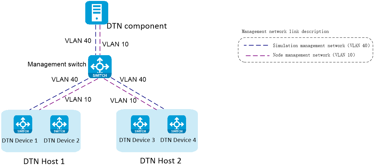
Table 8 Simulation management network IP address plan example
|
Component/node name |
IP address |
Interfaces |
|
DTN component |
Subnet: 192.168.12.133/24 (gateway address: 192.168.12.1) |
Ten-GigabitEthernet1/0/25 VLAN 40 |
|
DTN host 1 |
Subnet: 192.168.12.134/24 (gateway address: 192.168.12.1) |
Ten-GigabitEthernet1/0/26 VLAN40 |
|
DTN host 2 |
Subnet: 192.168.12.135/24 (gateway address: 192.168.12.1) |
Ten-GigabitEthernet1/0/27 VLAN40 |
|
DTN device 1 |
Subnet: 192.168.11.134/24 (gateway address: 192.168.11.1) |
VLAN40 |
|
DTN device 2 |
Subnet: 192.168.11.135/24 (gateway address: 192.168.11.1) |
VLAN40 |
|
DTN device 3 |
Subnet: 192.168.21.134/24 (gateway address: 192.168.21.1) |
VLAN40 |
|
DTN device 4 |
Subnet: 192.168.21.135/24 (gateway address: 192.168.21.1) |
VLAN40 |
Table 9 Node management network IP address plan example
|
Component/node name |
IP address |
Interfaces |
|
DTN component |
Subnet: 192.168.10.111/24 (gateway address: 192.168.10.1) |
Ten-GigabitEthernet1/0/22 VLAN 10 |
|
DTN host 1 |
Subnet: 192.168.10.112/24 (gateway address: 192.168.10.1) |
Ten-GigabitEthernet1/0/23 VLAN 10 |
|
DTN host 2 |
Subnet: 192.168.10.113/24 (gateway address: 192.168.10.1) |
Ten-GigabitEthernet1/0/24 VLAN 10 |
Configuration example
In the simulation environment, the VLAN must be the same for interfaces connecting the management switch to the DTN component and different DTN hosts. The interface connected to the simulation management network belongs to VLAN 40, and the interface connected to the node management network belongs to VLAN 10. On the corresponding VLAN interface, configure the gateway addresses for the simulation management network and all switch management networks.
Perform the following tasks on the management switch:
1. Create the VLANs for the simulation management network and node management network. In this example, the VLAN IDs are 40 and 10, respectively.
[device] vlan 40
[device-vlan40] quit
[device] vlan 10
[device-vlan10] quit
2. Assign to VLAN 40 the interface connecting the management switch to the simulation microservice component upstream port, Ten-GigabitEthernet 1/0/25 in this example.
Assign to VLAN 10 the interface connecting the management switch to the network card where the node management IP of the simulation component, Ten-GigabitEthernet 1/0/22 in this example.
[device] interface Ten-GigabitEthernet1/0/25
[device-Ten-GigabitEthernet1/0/25] port link-mode bridge
[device-Ten-GigabitEthernet1/0/25] port access vlan 40
[device-Ten-GigabitEthernet1/0/25] quit
[device] interface Ten-GigabitEthernet1/0/22
[device-Ten-GigabitEthernet1/0/22] port link-mode bridge
[device-Ten-GigabitEthernet1/0/22] port access vlan 10
[device-Ten-GigabitEthernet1/0/22] quit
3. Assign to VLAN 40 the interface connecting the management switch to the network card where the simulation management IP of the DTN host 1, Ten-GigabitEthernet 1/0/26 in this example.
Assign to VLAN 10 the interface connecting the management switch to the network card where the node management IP of the DTN host 1, Ten-GigabitEthernet 1/0/23 in this example.
[device] interface Ten-GigabitEthernet1/0/26
[device-Ten-GigabitEthernet1/0/26] port link-mode bridge
[device-Ten-GigabitEthernet1/0/26] port access vlan 40
[device-Ten-GigabitEthernet1/0/26] quit
[device] interface Ten-GigabitEthernet1/0/23
[device-Ten-GigabitEthernet1/0/23] port link-mode bridge
[device-Ten-GigabitEthernet1/0/23] port access vlan 10
[device-Ten-GigabitEthernet1/0/23] quit
4. Assign to VLAN 40 the interface connecting the management switch to the network card where the simulation management IP of the DTN host 2, Ten-GigabitEthernet 1/0/27 in this example.
Assign to VLAN 10 the interface connecting the management switch to the network card where the node management IP of the DTN host 2, Ten-GigabitEthernet 1/0/24 in this example.
[device] interface Ten-GigabitEthernet1/0/27
[device-Ten-GigabitEthernet1/0/27] port link-mode bridge
[device-Ten-GigabitEthernet1/0/27] port access vlan 40
[device-Ten-GigabitEthernet1/0/27] quit
[device] interface Ten-GigabitEthernet1/0/24
[device-Ten-GigabitEthernet1/0/24] port link-mode bridge
[device-Ten-GigabitEthernet1/0/24] port access vlan 10
[device-Ten-GigabitEthernet1/0/24] quit
5. Create a VPN instance.
[device] ip vpn-instance simulation
[device-vpn-instance-simulation] quit
6. Create a VLAN interface, and bind it to the VPN instance. Assign all gateway IP addresses to the VLAN interface.
[device] interface Vlan-interface40
[device-Vlan-interface40] ip binding vpn-instance simulation
[device-Vlan-interface40] ip address 192.168.12.1 255.255.255.0
[device-Vlan-interface40] ip address 192.168.11.1 255.255.255.0 sub
[device-Vlan-interface40] ip address 192.168.21.1 255.255.255.0 sub
[device-Vlan-interface40] quit
Deploy the simulation service on the controller
|
|
CAUTION: · Make sure SeerEngine-DC and DTN have been deployed. For the deployment procedure, see H3C SeerEngine-DC Installation Guide (Unified Platform). · In the current software version, the system administrator and tenant administrator can perform tenant service simulation. |
Preconfigure the simulation network
Preconfiguring a simulation network includes adding simulation hosts and uploading simulation images.
· Adding simulation hosts—A host refers to a physical server installed with the H3Linux system and configured with related settings. The simulated devices in the simulation network model are created on the host. If multiple hosts are available, the controller selects a host with optimal resources for creating simulated devices.
· Uploading simulation images—Physical devices on the real network can build the corresponding simulated devices based on the uploaded simulation images.
· Configuring parameters—You can configure license server-related parameters on the Parameters page.
Add simulation hosts
1. Log in to the controller. Navigate to the Automation > Data Center Networks > Simulation > Build Simulation Network page. Click Preconfigure. The Manage Simulation Hosts page opens.
2. Click Add. In the dialog box that opens, configure the host name, IP address, username, and password.
Figure 17 Adding simulation hosts
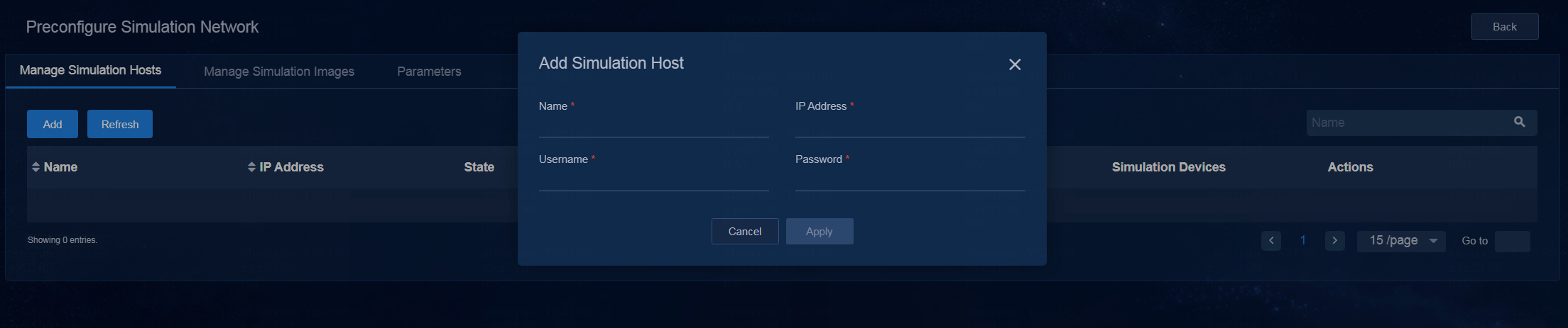
3. Click Apply.
|
|
NOTE: · A host can be incorporated by only one DC controller cluster. · The controller allows you to incorporate DTN hosts as a root user or non-root user. When you incorporate DTN hosts as a non-root user, you must add the non-root user privilege before incorporating DTN hosts as follows. To do that, execute the ./addPermission.sh username command in the SeerEngine_DC_DTN_HOST-version/ directory of the decompressed dependency package. |
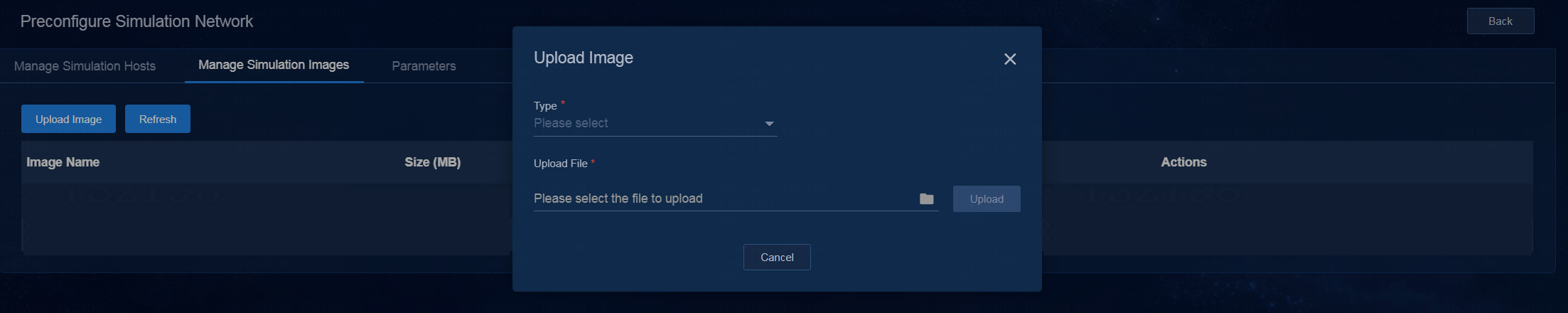
Upload simulation images
1. Log in to the controller. Navigate to the Automation > Data Center Networks > Simulation > Build Simulation Network page. After clicking Preconfigure, click the Manage Simulation Images tab. The page for uploading simulation images opens.
2. Click Upload Image. In the dialog box that opens, select the type of the image to be uploaded and image of the corresponding type, and then click Upload.
Figure 18 Uploading simulation images
Configure parameters
Because the simulation network is isolated from the controller network, simulated devices cannot connect to the license server configured for the SeerEngine-DC controller. Therefore, you must separately deploy a license server for the simulated devices. The license server provides licensing services for simulated devices.
Deploy the license server on a simulation host
Obtain the license server installation package and upload it to the server where the DTN host resides. If there are multiple DTN hosts, upload the package to any server. For more information, see H3C License Server Installation Guide.
|
|
NOTE: In the address bar of the browser, enter the Web login address for the license server in the format of https://lics_ipv4_address:port/licsmgr or https://[lics_ipv6_address]:port/licsmgr. In the Web login address, the lics_ipv4_address or lics_ipv6_address parameter specifies the management IP address of the DTN host node where the license server is deployed, and the port parameter specifies the HTTPS port for the Web login when the license server is deployed. |
Configure license server-related parameters on the page
1. Navigate to the Automation > Data Center Networks > Simulation > Build Simulation Network page. Click Preconfigure. On the page that opens, click the Parameters tab.
2. Configure license server-related parameters on this tab.
Figure 19 Parameters page
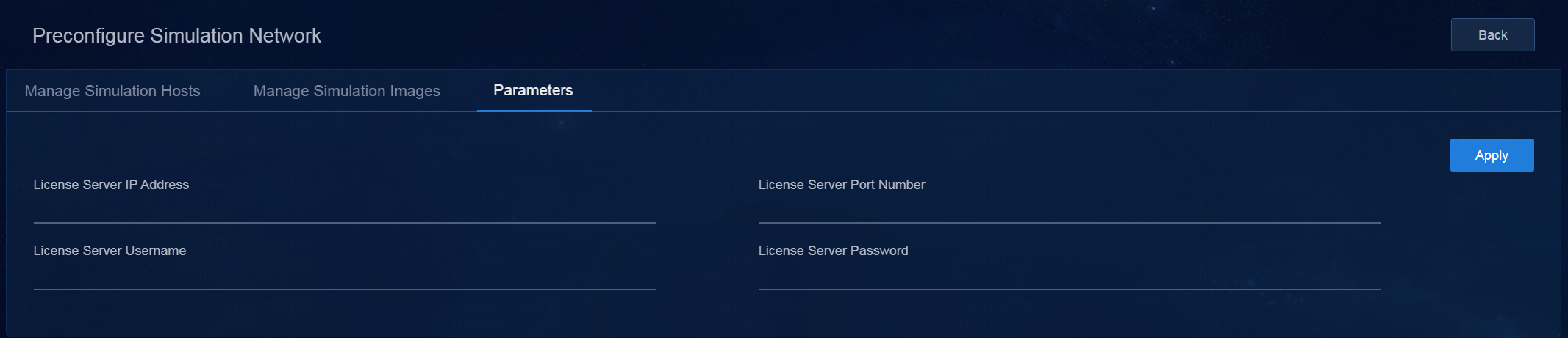
3. Click Apply.
Build a simulation network
After preconfiguring the simulation network and controller, you can build a simulation network.
|
|
CAUTION: If the local licensing method is used, you must reinstall licenses for all simulated devices after rebuilding the simulation network. |
Follow these steps to build a simulation network:
1. Log in to the controller. Navigate to the Automation > Data Center Networks > Simulation > Build Simulation Network page.
Figure 20 Building a simulation network
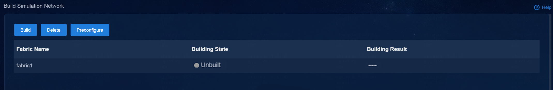
2. Click Build Simulation Network. In the dialog box that opens, select fabric1.
Figure 21 Selecting a fabric
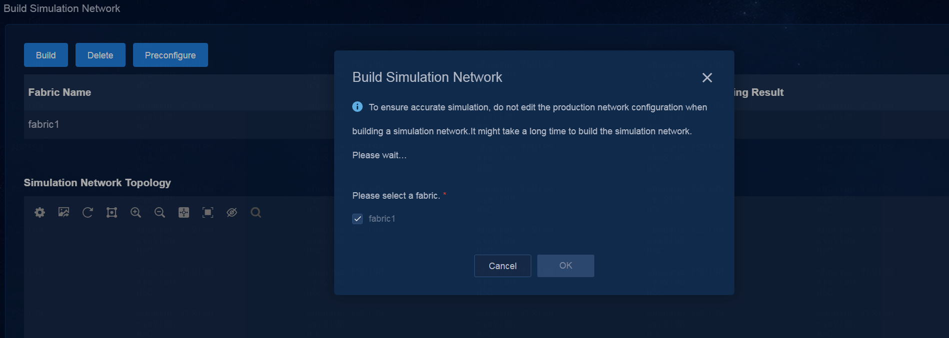
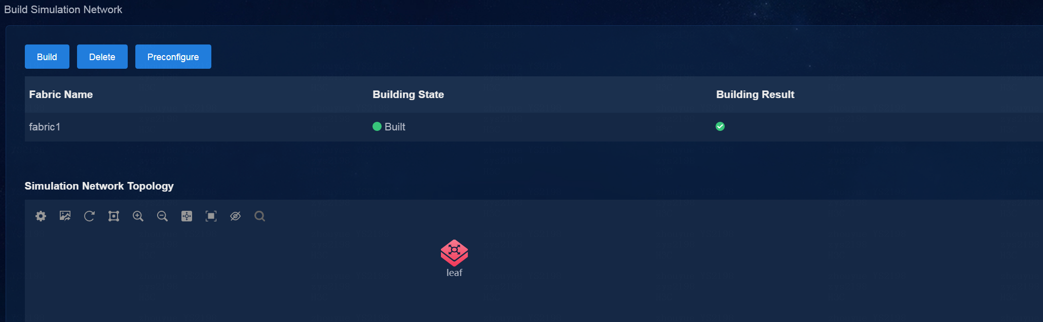
3. Click OK to start building a simulation network. In the current software version, you can build a simulation network for only one fabric. During the process of building a simulation network, you can view the building workflow and result.
Figure 22 Built a simulation network successfully
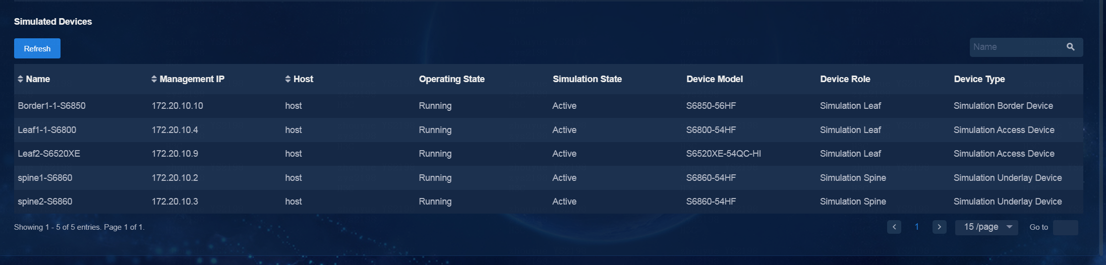
4. After the simulation network is built successfully, you can view the simulated device information:
¡ The simulated state is Active.
¡ The device model is displayed correctly on the real network and the simulation network.
The VMs in the simulation network model are created on the host created. If multiple hosts are available, the controller selects a host with optimal resources for creating VMs.
Figure 23 Viewing simulated devices
Simulate the tenant service
After the simulation network is successfully built, you can perform tenant service simulation. Tenant service simulation involves the following steps:
1. Enable the design mode for the specified tenant
To perform tenant simulation service orchestration and simulation service verification, make sure the design mode is enabled for the specified tenant.
The services orchestrated in design mode are deployed only to simulated devices rather than real devices. To deploy the orchestrated services to real devices, click Deploy Configuration.
After you disable the design mode for a tenant, service data that has not been deployed or failed to be deployed in the tenant service simulation will be retrieved.
2. Configure tenant service simulation
This feature allows you to orchestrate and configure logical network resources, including vRouters, vNetworks, and subnets. After the configuration is completed, evaluate the simulation.
3. Evaluate the simulation and view the simulation result
The simulation evaluation function allows you to evaluate the configured resources, and it includes capacity evaluation and network-wide impact analysis.
¡ Capacity evaluation—Computes the device resources (including VSIs, VSI-interfaces, VRFs, ACs, and routes) occupied by the deployed service.
¡ Network-wide impact analysis—Verifies the impact of the deployed service on the connectivity of the overlay network links, and identifies the links with state changes.
After simulation evaluation is completed, you can view the simulation results, including the capacity and configuration changes, connectivity simulation results, and network-wide impact analysis results.
4. Deploy configuration and view deployment details
You can deploy the service configuration to real devices when the simulation evaluation result is as expected.
Enabling the design mode for the tenant
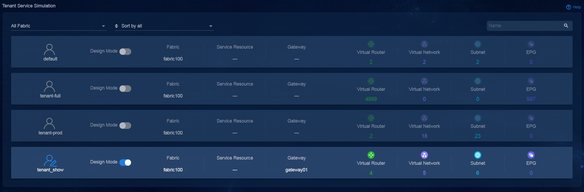
1. Navigate to the Automation
> Data Center Networks > Simulation > Tenant Service Simulation page. Click the design mode
icon for a tenant to enable or disable design mode for the tenant. After design
mode is enabled for a tenant, the tenant icon becomes ![]() , which
means that the tenant is editable. After design mode is disabled for a tenant,
the tenant icon becomes
, which
means that the tenant is editable. After design mode is disabled for a tenant,
the tenant icon becomes ![]() , which indicates that the tenant is not editable.
, which indicates that the tenant is not editable.
2. Click the icon for the tenant to enter the Tenant Service Simulation (Tenant Name) > Logical Networks page. On this page, you can perform tenant service simulation.
|
|
NOTE: You can enable the design mode and then perform tenant service simulation only when the simulation network is built normally. |
Figure 24 Enabling the design mode for the tenant
Configure tenant service simulation
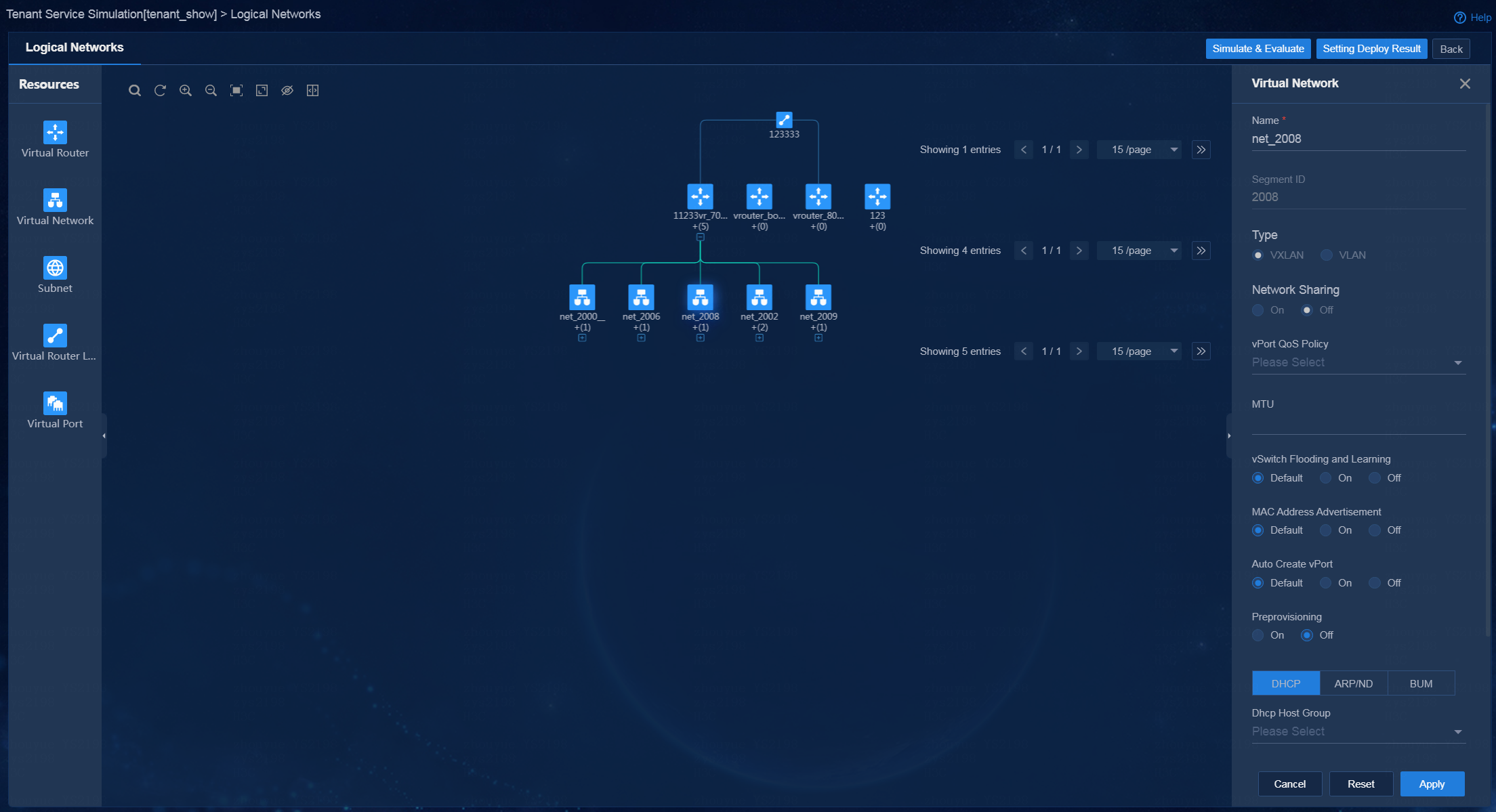
1. On the logical network page, you can perform the following operations:
¡ Drag a resource icon in the Resources area to the canvas area. Then, a node of this resource is generated in the canvas area, and the configuration panel for the resource node opens on the right.
¡ In the canvas area, you can adjust node locations, bind/unbind resource, and zoom in/out the topology.
Figure 25 Logical networks
2. After resources are configured, click Simulate & Evaluate to evaluate the simulation.
Evaluate the simulation and view the simulation result
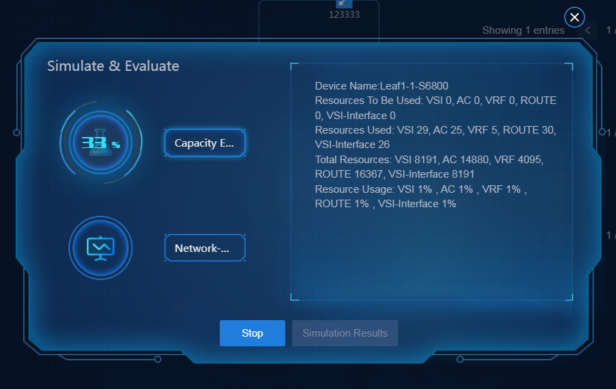
Simulate and evaluate services
Click Simulate & Evaluate. In the dialog box that opens, select Network-Wide Impact Analysis, and click Start. In the left area of the Simulate & Evaluate dialog box, the progress in percentage is displayed. In the right area, the corresponding resource changes are displayed.
Figure 26 Simulating and evaluating services (1)
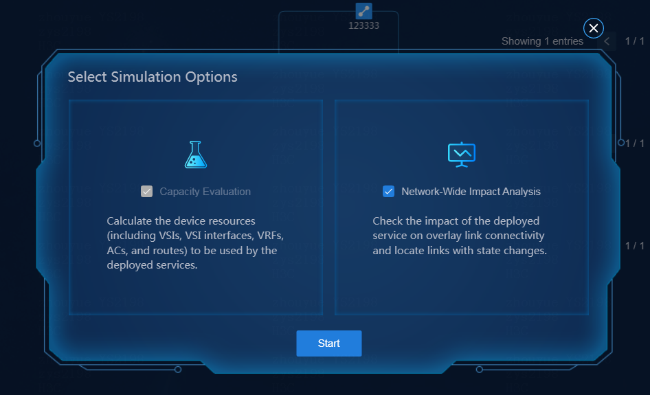
Figure 27 Simulating and evaluating services (2)
View the simulation result
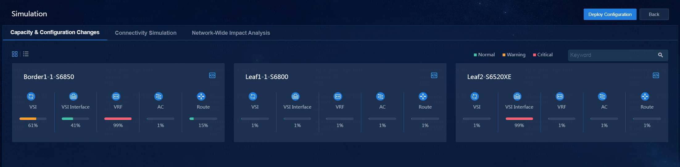
After simulation evaluation is completed, click Simulation Results to enter the simulation result page. On this page, you can view the following simulation results:
· Capacity & Configuration Changes—This page displays resource usages and the configuration changes before and after simulation in a list or block diagrams.
Figure 28 Capacity and configuration changes
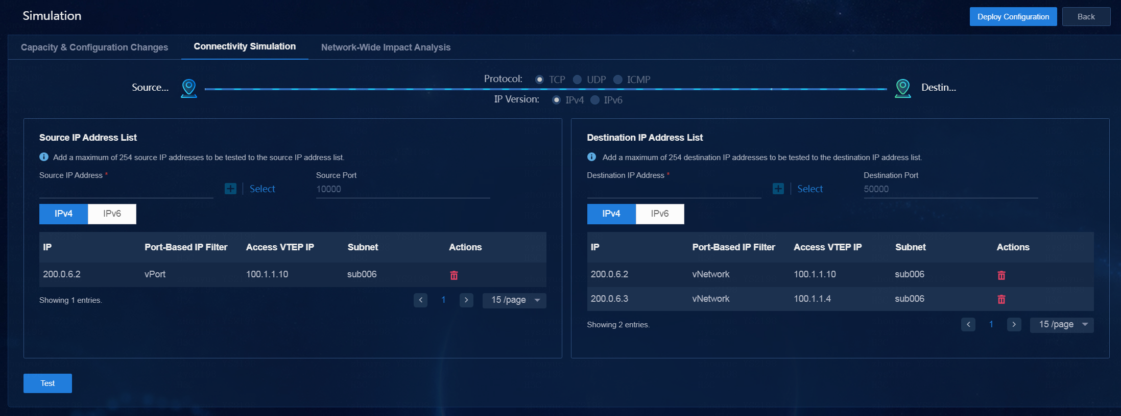
· Connectivity Simulation—Perform this task to detect connectivity between source addresses and destination addresses. When specifying the source/destination addresses, you can input IP addresses or click Select and configure filter conditions in the dialog box that opens. Then, all the specified IP addresses are displayed on the source or destination IP address list. After completing the configuration, click Test to detect connectivity.
Figure 29 Connectivity detection
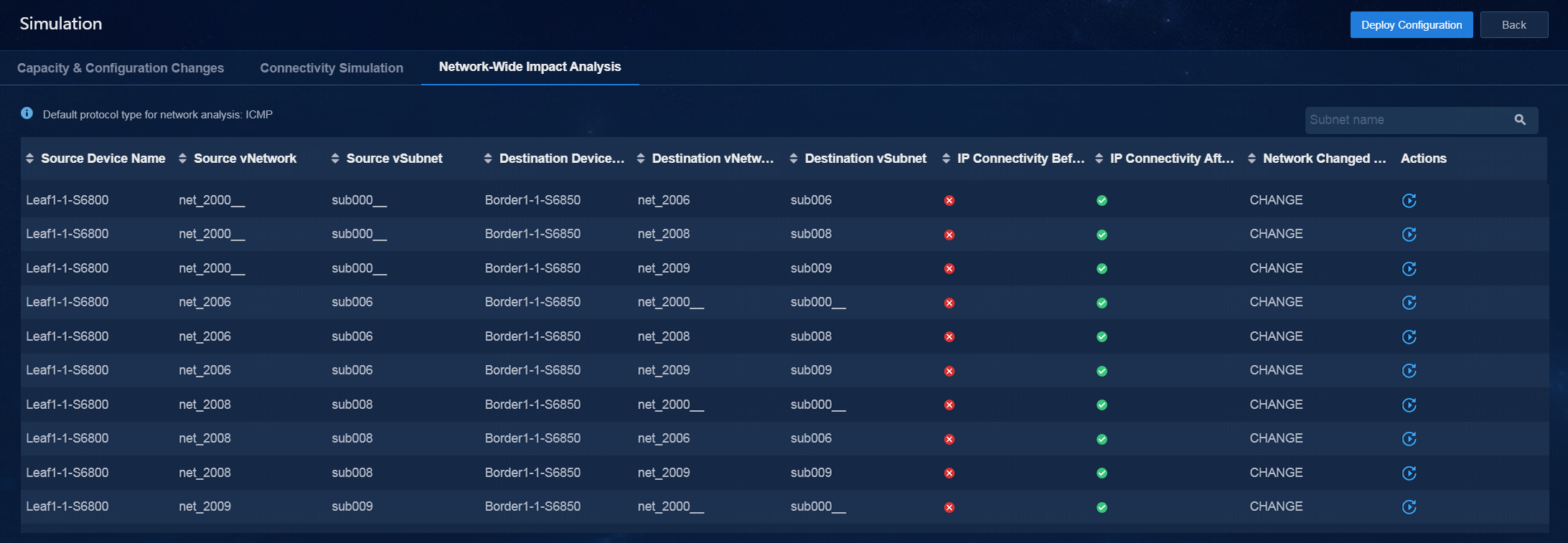
· Network-Wide Impact Analysis—From this tab, you can view details of network information and perform a detection again. A single tenant supports performing network-wide impact analysis for up to 254 ports.
Figure 30 Network-wide impact analysis
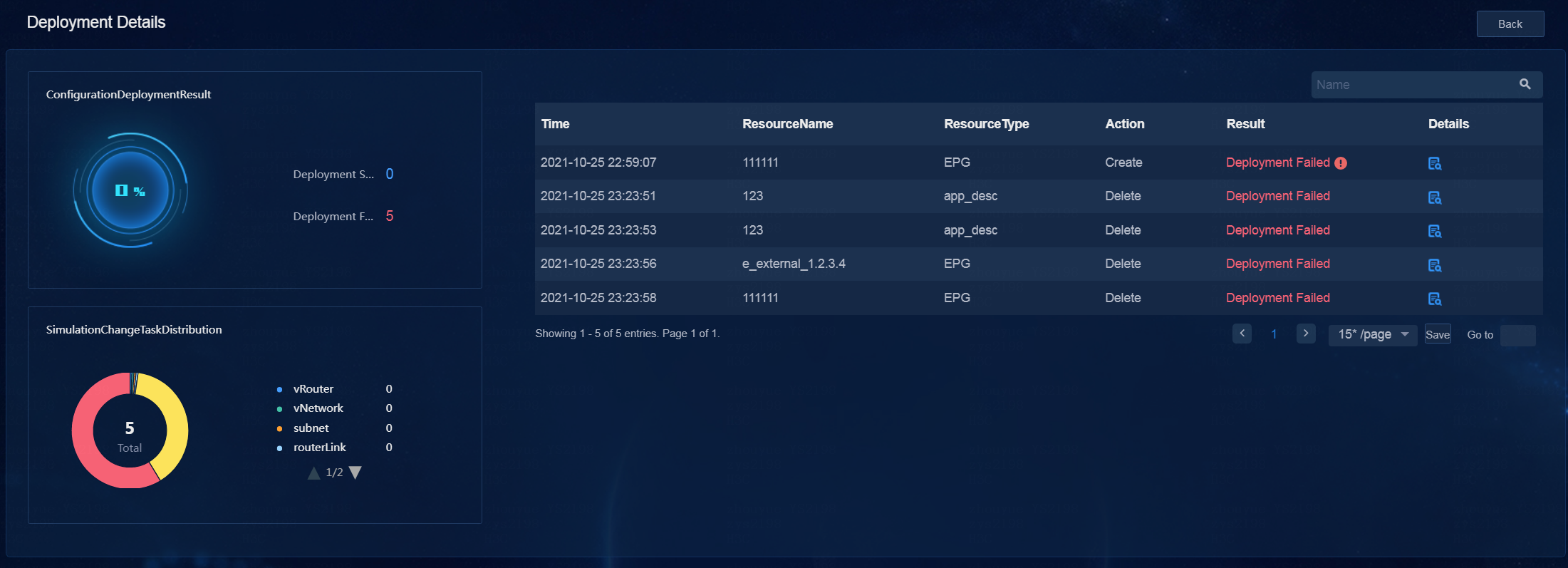
Deploy configuration and view deployment details
You can click Deploy Configuration to deploy the service configuration to real devices when the simulation evaluation result is as expected. Additionally, you can view details on the deployment details page.
Figure 31 Viewing deployment details
Delete a simulation network
1. Log in to the controller. Navigate to the Automation > Data Center Networks > Simulation > Build Simulation Network page.
2. Click Delete. In the dialog box that opens, the fabric for which a simulation network has been built is selected by default.
Figure 32 Deleting a simulation network
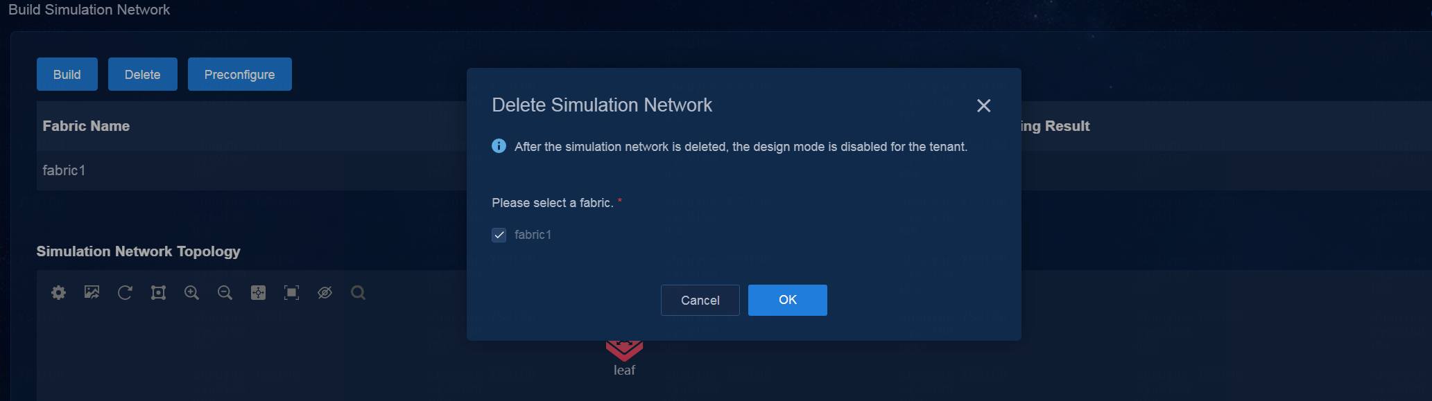
3. Click OK to start deleting the simulation network. When all operation results are displayed as Succeeded and the progress is 100%, the simulation network is deleted completely.
Upgrade the DTN hosts and dependency packages
Upgrade operations include full upgrade and dependency package upgrade. To upgrade the system image, select full upgrade and upgrade both the image and dependency packages, and redeploy the simulation service on the controller. In any other cases, upgrade only the dependency package.
Full upgrade
In full upgrade, you need to install the image and dependency packages of the new version, and redeploy the simulation service on the controller. For how to install the operating system, see “Install the operating system.” For how to install the dependency packages, see “Install dependency packages.”
|
|
NOTE: If you upgrade from an ISO image file (with the DTN Manager application embedded) of an old version to the ISO image file (without the DTN Manager embedded) of the new version, after the DTN component is upgraded on the Unified Platform, you must delete old hosts on the simulation network and then incorporate them again. |
Upgrading the dependency packages
1. Obtain the latest dependency packages, and upload them to the server and compress them. The dependency package format is SeerEngine_DC_DTN_HOST-version.zip, where the version field represents the software version number. In this example, use E6103.
[root@host01 root]# unzip SeerEngine_DC_DTN_HOST-E6103.zip
2. Execute the chmod command to assign permissions to the user.
[root@host01 root]# chmod +x -R SeerEngine_DC_DTN_HOST-E6103
3. Enter the SeerEngine_DC_DTN_HOST-version/ directory of the decompressed dependency package, and execute the ./install.sh command to upgrade the dependency package.
[root@host01 SeerEngine_DC_DTN_HOST-E6103]# ./upgrade.sh
Redirecting to /bin/systemctl restart libvirtd.service
Libvirt configuration succeeded
Upgrade succeeded
