- Table of Contents
-
- H3C S10500X Switch Series Installation Guide-6W107
- 00-Preface
- 01-Chapter 1 Preparing for Installation
- 02-Chapter 2 Installing the Switch
- 03-Chapter 3 Installing FRUs
- 04-Chapter 4 Connecting Your Switch to the Network
- 05-Chapter 5 Replacement Procedures
- 06-Appendix A Chassis Views and Technical Specifications
- 07-Appendix B FRUs and Compatibility Matrixes
- 08-Appendix C LEDs
- 09-Appendix D Cables
- 10-Appendix E Engineering Labels for Cables
- 11-Appendix F Cable Management
- 12-Appendix G Repackaging the Switch
- Related Documents
-
| Title | Size | Download |
|---|---|---|
| 09-Appendix D Cables | 422.94 KB |
Contents
9 Appendix D Cables
This chapter describes cables used for connecting interfaces on the cards.
Table 9-1 Cable description
|
Cable |
Port type |
Application |
|
Console cable |
Console port at one end and 9-pin serial port at the other end |
Enables users to perform debugging, configuration, maintenance, management, and software loading on the device. |
|
USB console cable |
USB console port at one end and USB port at the other end |
|
|
RJ-45 Ethernet ports |
Transmits data. |
|
|
SFP+/SFP/CFP/QSFP+ ports |
Transmits data. |
|
|
· SFP+ DAC cable: Connects SFP+ ports · SFP28 DAC cable: Connects SFP28 ports |
Transmits data. |
|
|
SFP28 ports |
Transmits data. |
|
|
· QSFP+ DAC cable: Connects QSFP+ ports · QSFP28 DAC cable: Connects QSFP28 ports |
Transmits data. |
|
|
· QSFP+ AOC cable: Connects QSFP+ ports · QSFP28 AOC cable: Connects QSFP28 ports |
Transmits data. |
|
|
A QSFP+ port at one end and four SFP+ ports at the other end |
Transmits data. |
|
|
NOTE: For information about the console cable and USB console cable, see "Setting up the configuration environment." |
Ethernet twisted pair cable
An Ethernet twisted pair cable consists of four pairs of insulated wires twisted together. It mainly transmits analog signals and is advantageous in transmitting data over shorter distances. The maximum transmission distance is 100 m (328.08 ft).
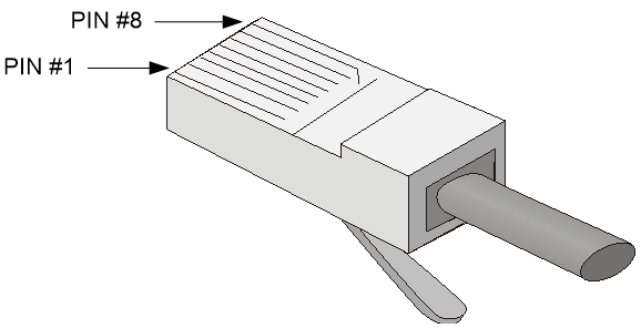
RJ-45 connector
An Ethernet twisted pair cable connects network devices through the RJ-45 connectors at the two ends. Figure 9-1 shows the pinouts of an RJ-45 connector.
Figure 9-1 RJ-45 connector pinout diagram
Cable pinouts
EIA/TIA cabling specifications define two standards: 568A and 568B for cable pinouts.
· Standard 568A—pin 1: white/green stripe, pin 2: green solid, pin 3: white/orange stripe, pin 4: blue solid, pin 5: white/blue stripe, pin 6: orange solid, pin 7: white/brown stripe, pin 8: brown solid.
· Standard 568B—pin 1: white/orange stripe, pin 2: orange solid, pin 3: white/green stripe, pin 4: blue solid, pin 5: white/blue stripe, pin 6: green solid, pin 7: white/brown stripe, pin 8: brown solid.
Cable type
Based on performance
Table 9-2 Ethernet cable description
|
Type |
Description |
|
Category 5 |
Transmits data at a maximum speed of 100 Mbps, with a bandwidth of 100 MHz. |
|
Category 5e |
Transmits data at a maximum speed of 1000 Mbps, with a bandwidth of 100 MHz. |
|
Category 6 |
Transmits data at a speed higher than 1 Gbps, with a bandwidth of 250 MHz. |
|
Category 6A |
Transmits data at a speed higher than 10 Gbps, with a bandwidth of 500 MHz. |
|
Category 7 |
Transmits data at a speed higher than 10 Gbps, with a bandwidth of 600 MHz. |
Based on pinouts
Ethernet twisted pair cables can be classified into straight through and crossover cables based on their pinouts.
· Straight-through—The pinouts at both ends comply with standard 568B, as shown in Figure 9-2.
· Crossover—The pinouts at one end comply with standard 568B, and those at the other end comply with standard 568A, as shown in Figure 9-3.
Figure 9-2 Straight-through cable

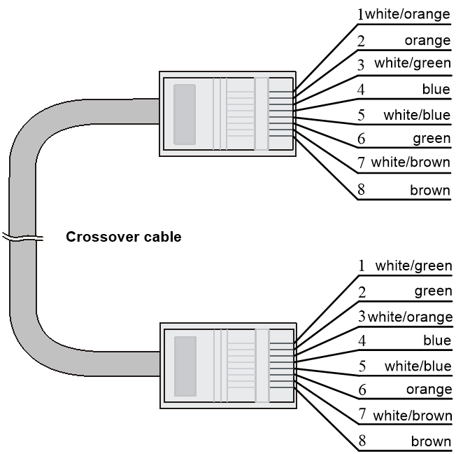
A cross-over cable connects devices of the same type. A straight-through cable connects devices of different types.
An RJ-45 Ethernet interface with MDI/MDIX autosensing enabled can automatically negotiate pin roles. The RJ-45 Ethernet interfaces on the switch support MDI/MDIX. By default, MDI/MDIX autosensing is enabled on a port.
Optical fiber
|
|
CAUTION: Use the same types of transceiver modules, pigtail cords, patch cords, and fiber cables. If you use single-mode optical fibers, the transceiver modules, pigtail cords, patch cords, and fiber cables must be single-mode. |
Optical fiber
Optical fibers are widely used in fiber-optic communications, which are advantageous for long-distance communications.
Optical fibers can be classified into the following types:
· Single mode fiber—It has a core size of 10 µm or smaller, and has a lower modal dispersion. It carries only a single ray of light. It is mostly used for communication over longer distances.
· Multi-mode fiber—It has a core size of 50 µm or 62.5 µm or higher, and has a higher modal dispersion than single-mode optical fiber. It is mostly used for communication over shorter distances.
Table 9-3 Allowed maximum tensile force and crush load
|
Period of force |
Tensile load (N) |
Crush load (N/mm) |
|
Short period |
150 |
500 |
|
Long term |
80 |
100 |
Optical fiber cable
An optical fiber cable is a cable containing one or more optical fibers. The optical fiber elements are typically individually coated with plastic layers and contained in a protective tube. Optical fiber cables fall into single-mode and multi-mode.
Patch cord
A fiber that has connectors at both ends is called a patch cord. A patch cord connects one optical device to another for signal routing. Patch cords fall into single-mode and multi-mode patch cords.
· Single-mode patch cord—The jacket is yellow. It permits transmission over longer distances.
· Multi-mode patch cord—The jacket is orange. It permits transmission over shorter distances.
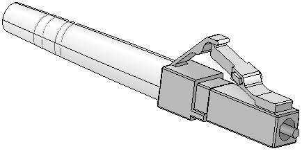
Patch cords are classified into SC, LC, FC, and so on based on interface type. The length of a patch cord can be 0.5 m (1.64 ft), 1 m (3.28 ft), 2 m (6.56 ft), 3 m (9.84 ft), 5 m (16.40 ft), 10 m (32.81 ft), and so on.
Pigtail cord
A pigtail cord is an optical fiber that has an optical connector on one end and a length of exposed fiber on the other. The end of the pigtail is fusion spliced to a fiber, connecting the fiber cable and transceiver.
Pigtail cords fall into single-mode (yellow) and multi-mode (orange), and can also be classified into SC, LC, FC, and so on based on interface type.
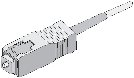
Fiber connector
Figure 9-4 SC connector
Precautions
· Make sure the fiber connector and fiber type match the transceiver module type.
· The fiber ports on some cards have shielded covers. Remove the shielded covers before using the fiber ports. Fiber interfaces must be installed with shielded covers when they are not in use. Keep them safely.
· Fiber connectors must be protected under safe and reliable outer packing, and be fitted with dust caps. Fiber connectors must be installed with dust caps when they are not in use. Take care not to scratch their end face. Replace the dust cap if it is loose or polluted.
· Before connecting a fiber, use dust free paper and absolute alcohol to clean the end face of the fiber connector. You can brush the end face only in one direction. You also need to brush the end face of the fiber port.
· If the fiber has to pass through a metallic board hole, the hole must have a sleek and fully filleted surface (the filleting radius must be not less than 2 mm). When passing through a metallic board hole or bending along the acute side of mechanical parts, the fiber must wear jackets or cushions.
· Insert and remove a plug with care. Never exert a fierce force to the fiber or plug; otherwise the plug might be damaged or the fiber might be broken. Never pull, press or extrude the fiber fiercely. For the allowed maximum tensile load and crush load, see Table 9-3.
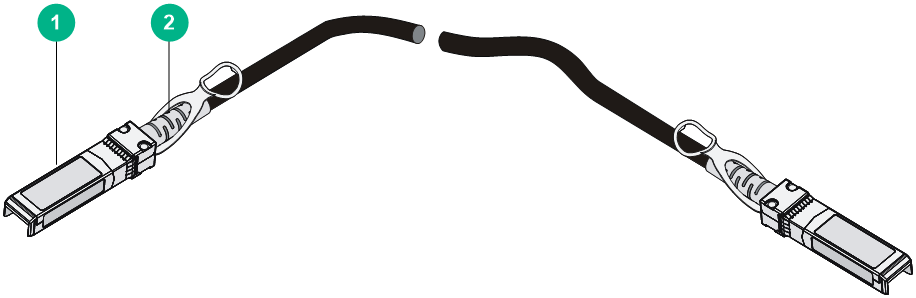
SFP+ DAC/SFP28 DAC cable
You can use SFP+ DAC cables to connect SFP+ ports. The SFP+ DAC cables available for the switch series are 10 G SFP+ Cu cables, as shown in Figure 9-6.
You can use SFP28 DAC cables to connect SFP28 ports. The SFP28 DAC cables are similar to SFP+ DAC cables in appearance.
Figure 9-6 SFP+ DAC cable
|
(1) Connector |
(2) Pull latch |
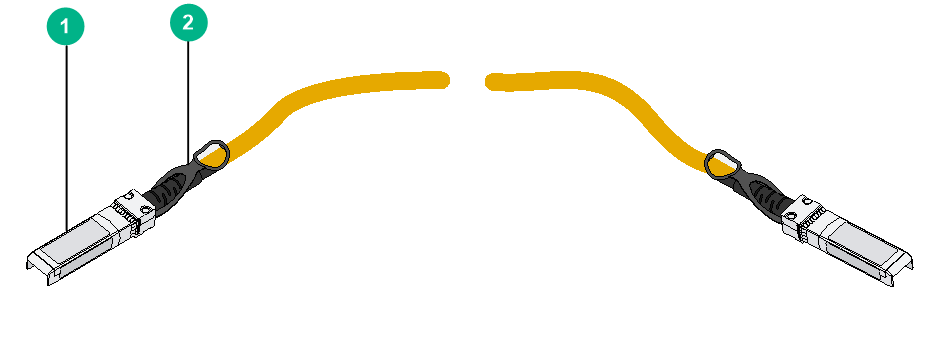
SFP28 AOC cable
You can use SFP28 AOC cables to connect SFP28 ports.
Figure 9-7 SFP28 AOC cable
|
(1) Connector |
(2) Pull latch |
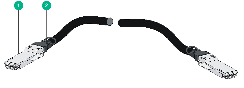
QSFP+ DAC/QSFP28 DAC cable
You can use QSFP+ DAC cables to connect QSFP+ ports.
You can use QSFP28 DAC cables to connect QSFP28 ports. The QSFP28 DAC cables are similar to QSFP+ DAC cables in appearance.
Figure 9-8 QSFP+ DAC cable
|
(1) Connector |
(2) Pull latch |
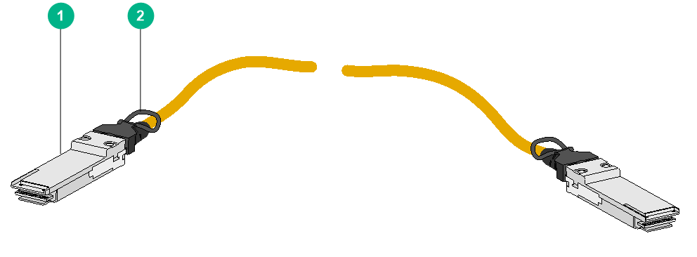
QSFP+ AOC/QSFP28 AOC cable
You can use QSFP+ AOC cables to connect QSFP+ ports.
You can use QSFP28 AOC cables to connect QSFP28 ports. The QSFP28 AOC cables are similar to QSFP+ AOC cables in appearance.
|
(1) Connector |
(2) Pull latch |
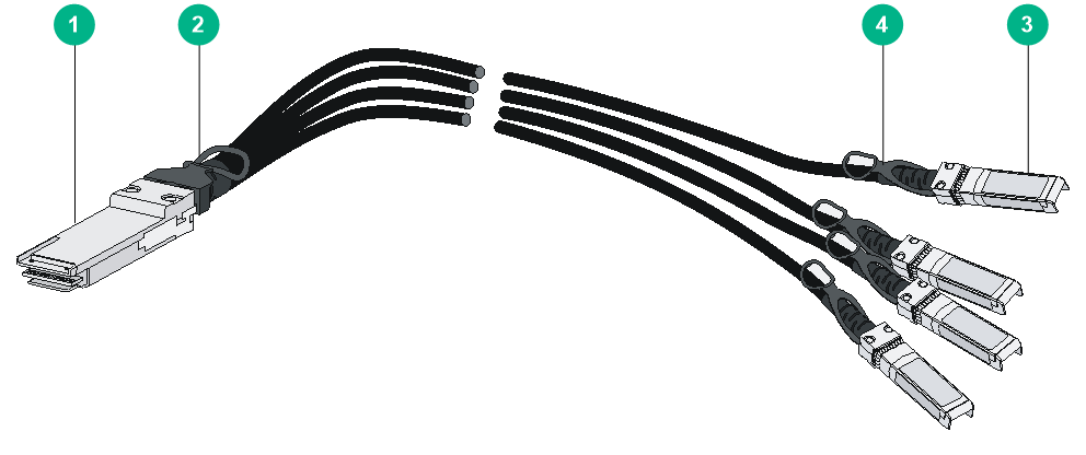
QSFP+ to SFP+ DAC cable
A QSFP+ to SFP+ DAC cable connects a QSFP+ module at one end and four SFP+ modules at the other end.
Figure 9-10 QSFP+ to SFP+ DAC cable
|
(1) QSFP+ connector |
(2) QSFP+ pull latch |
|
(3) SFP+ connector |
(4) SFP+ pull latch |
