- Table of Contents
-
- 01-Fundamentals Configuration Guide
- 00-Preface
- 01-CLI Configuration
- 02-Login Management Configuration
- 03-FTP and TFTP Configuration
- 04-File System Management
- 05-Configuration File Management Configuration
- 06-Software Upgrade Configuration
- 07-ISSU Configuration
- 08-Device Management Configuration
- 09-Automatic Configuration
- 10-Management with BootWare
- Related Documents
-
| Title | Size | Download |
|---|---|---|
| 06-Software Upgrade Configuration | 252.85 KB |
Contents
Specifying a startup system software image
Hotfix configuration task list
Installing and running a patch in one step
Installing a patch step by step
Uninstalling a patch step by step
Upgrading MBUS daughter card software
Upgrading or repairing the power software on an interface card
Upgrading the power monitor software
Upgrading fan monitor software
Displaying and maintaining software image settings
System software image upgrade example (in standalone mode)
System software image upgrade example (in IRF mode)
Scheduled upgrade configuration example
Software can be upgraded from BootWare menus or from the CLI. This chapter covers only upgrading software from the CLI. For information about upgrading software from BootWare menus, see "Managing the system with BootWare."
Overview
Upgrading software includes upgrading the BootWare image, system software image, maintenance bus (MBUS) daughter card software, CPLDs, power monitoring module software, and fan monitor software.
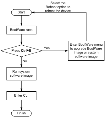
Each time the switch is powered on, it runs the BootWare image to initialize hardware and display hardware information. Then, the switch runs the system software image (called "boot file" or "application file" in software code). The system software image provides drivers and adaption for hardware, and implements service features. The BootWare image and system software image are required for the startup and running of a switch.
Figure 1 System startup process
FIPS compliance
The switch supports the FIPS mode that complies with NIST FIPS 140-2 requirements. Support for features, commands, and parameters might differ in FIPS mode and non-FIPS mode. For more information about FIPS mode, see Security Configuration Guide.
Software upgrade task list
The system software image file (with the file extension .bin) comprises the BootWare image, MBUS daughter card software, and power monitor software, which are automatically upgraded when the system software image is upgraded. You can also upgrade the BootWare image, MBUS daughter card software, and power monitor software separately.
To upgrade software from the CLI, perform the following tasks as appropriate:
|
Task |
Remarks |
|
Optional. |
|
|
Optional. |
|
|
Optional. |
|
|
Optional. |
|
|
Optional. |
|
|
Upgrading or repairing the power software on an interface card |
Optional. |
|
Optional. |
|
|
Optional. |
Upgrading BootWare
The BootWare image is automatically upgraded when you upgrade the system software image. You can also perform the tasks in this section to upgrade the BootWare image separately.
To upgrade the BootWare image on an MPU, save the upgrade file in the root directory of a storage medium on the MPU.
To upgrade the BootWare image for an interface card or a switching fabric module:
· In standalone mode—Save the upgrade file in the root directory of a storage medium on the active MPU.
· In IRF mode—Save the upgrade file in the root directory of a storage medium on the active MPU of the member switch that hosts the card.
If the storage medium has been partitioned, save the upgrade file to the root directory of the first partition.
Names of the BootWare image files on each MPU can be different, but their versions must be the same for a correct startup.
In FIPS mode, the file must pass authenticity verification before it can be set as the BootWare image file.
After upgrading the BootWare image, you must restart the switch to validate the upgrade.
To upgrade the BootWare image on a card:
|
Task |
Command |
Remarks |
|
Upgrade the BootWare image on a card (in standalone mode). |
bootrom update file file-url slot slot-number-list |
Available in user view. |
|
Upgrade the BootWare image on a card (in IRF mode). |
bootrom update file file-url chassis chassis-number slot slot-number-list |
Available in user view. |
To upgrade the BootWare image of the OAM module on an MPU:
|
Task |
Command |
Remarks |
|
Upgrade the BootWare image of the OAM module on an MPU (in standalone mode). |
oam-bootrom update file file-url slot slot-number |
Available in user view. |
|
Upgrade the BootWare image of the OAM module on an MPU (in IRF mode). |
oam-bootrom update file file-url chassis chassis-number slot slot-number |
Available in user view. |
Upgrading the system software
To upgrade the system software (in standalone mode):
1. Use FTP, TFTP, or any other method to save the upgrade system software image file to the root directory of the active MPU's storage medium (Flash or CF card).
2. Copy the file to the root directory of the standby MPU's storage medium (Flash or CF card).
3. Specify the file as the main startup system software image file on both MPUs. For more information, see "Specifying a startup system software image."
4. Reboot the switch to complete the upgrade.
To upgrade the system software (in IRF mode):
1. Use FTP, TFTP, or any other method to save the upgrade system software image file to the root directory of the global active MPU's storage medium (Flash or CF card).
2. Copy the file to the root directory of the storage medium (Flash or CF card) on each MPU in the IRF fabric.
3. Specify the system software image file as the main startup system software image file on all the MPUs. For more information, see "Specifying a startup system software image."
4. Reboot the switch to complete the upgrade.
Specifying a startup system software image
You can specify one main startup system software image and one backup startup system software image on each MPU. The main system software image is always preferred over the backup system image at startup.
The startup system software image files must be saved in the root directory of the Flash or CF card. If a partitioned CF card is used, the image files must be saved in the root directory of the first partition.
In FIPS mode, the specified file must pass authenticity verification before it can be set as a startup system software image file.
To upgrade system software image:
|
Task |
Command |
Remarks |
|
Specify a startup system software image (in standalone mode). |
boot-loader file file-url slot slot-number { main | backup } |
Available in user view. |
|
Specify a startup system software image (in IRF mode). |
boot-loader file file-url chassis chassis-number slot slot-number { main | backup } |
Available in user view. |
Synchronizing the main startup system software image from the active MPU to the standby MPU in standalone mode
This section does not apply to the IRF mode.
Use the display device command to examine the state of the standby MPU. If its state is Fault, upgrade the standby MPU from the BootWare menu or remove the standby MPU and upgrade it. If its state is Slave, execute the boot-loader update command, and the system automatically upgrades the system software on the standby MPU to be the same as the active MPU, and reboots the standby MPU with the new system software image.
Before upgrading system software for the standby MPU, verify that the standby MPU has sufficient storage space for the new system software image. If the sum of the free space and the space occupied by the old system software image is greater than the size of the new system software image, the switch automatically deletes the old system software image before the upgrade.
In FIPS mode, the file must pass authenticity verification before it can be set as the main startup system software image file on the standby MPU.
To upgrade system software on the standby MPU:
|
Task |
Command |
Remarks |
|
Upgrade the system software image of the standby MPU (in standalone mode). |
boot-loader update slot slot-number |
Available in user view. |
Installing hotfixes
Hotfixes (called "patches" in this document) repair software defects without requiring a system reboot.
Basic concepts
Patch, patch file and patch package file
A patch fixes certain software defects.
A patch file contains one or more patches. A patch package file contains patch files for multiple features. It enables you to use one command to bulk-fix bugs for multiple features.
Incremental patch
Incremental patches add enhancements to the system.
Patches that have been released are all incremental patches.
Common patch and temporary patch
Common patches are formally released to users.
A common patch always includes the functions of its previous temporary patches. The system deletes all the temporary patches before loading the common patch.
Patch states
A patch is in IDLE, DEACTIVE, ACTIVE, or RUNNING state, depending on the patch manipulation command.
Patch manipulation commands include patch load (load), patch active (run temporarily), patch run (confirm running), patch deactive (stop running), patch delete (delete), patch install (install), and undo patch install (uninstall).
For example, if you execute the patch active command, patches in DEACTIVE state change to the ACTIVE state.
Figure 2 shows the patch manipulation commands and how they affect the patch state.
|
|
IMPORTANT: Patch state information is saved in the patchstate file on the Flash. To make sure the switch can correctly find the patches, do not edit, delete, move the file, or change the file name. |
Figure 2 Impact of patch manipulation commands on patch state
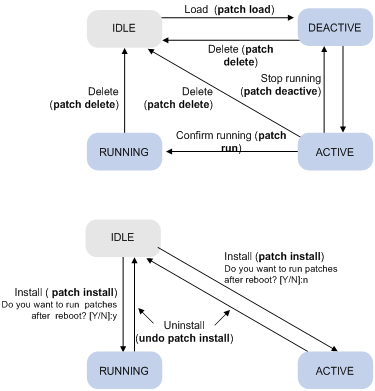
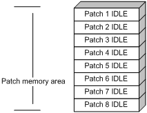
IDLE state
Patches that have not been loaded are in IDLE state. You cannot install or run these patches. As shown in Figure 3, the patch memory area can load up to eight patches.
The patch memory area supports up to 200 patches.
Figure 3 Patches that are not loaded to the patch memory area
DEACTIVE state
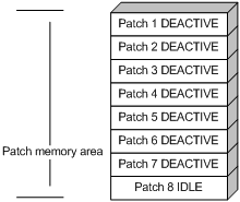
Patches in DEACTIVE state have been loaded to the patch memory area but have not run in the system. Suppose the patch file you are loading has seven patches. After the seven patches successfully pass the version check and CRC check, they are loaded to the patch memory area and are in DEACTIVE state. In the patch memory area, patch states are as shown in Figure 4.
Figure 4 Patch states in the patch memory area after a patch file is loaded
ACTIVE state
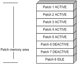
Patches in ACTIVE state run temporarily in the system and become DEACTIVE at a reboot. For the seven patches in Figure 4, if you activate the first five patches, their states change from DEACTIVE to ACTIVE. The patch states in the system are as shown in Figure 5.
The patches that are in ACTIVE state are in DEACTIVE state at a reboot.
Figure 5 Patches are activated
RUNNING state
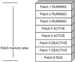
After you confirm ACTIVE patches, their states change to RUNNING and persist after a reboot. In contrast to ACTIVE patches, RUNNING patches continue to take effect after a reboot. For example, if you confirm the first three patches in Figure 5, their states change from ACTIVE to RUNNING, and the RUNNING state persists after a reboot. The patch states of the system are as shown in Figure 6.
The patches that are in RUNNING state are still in RUNNING state after system reboot.
Figure 6 Patches in RUNNING state
Hotfix configuration task list
|
Task |
Remarks |
|
Install patches: |
Use either method. Step-by-step patch installation allows you to control the patch status. |
|
Optional. |
Configuration prerequisites
To ensure a successful hotfix operation and normal switch operation after the hotfix operation:
· Make sure each patch file you are installing matches the switch model, card type, and software version.
· In standalone mode, save the patch files for the active MPU, interface cards, or switching fabric modules to the root directory of the active MPU's storage media, and save the patch files for the standby MPU to the root directory of the standby MPU's storage media.
· In IRF mode, save the patch files for the active MPU, interface card, or switching fabric module to the root directory of the storage media on each member device's active MPU, and save the patch files for the standby MPU to the root directory of the storage media on each member device's standby MPU.
· Make sure the patch files for the active MPU and the standby MPU are the same.
· To use a patch package file, save the patch package file to the root directory of a storage medium on each MPU before patch installation.
· If a partitioned CF card is used, save the patch files or patch package files to the root directory of the first partition.
· Correctly name a patch file in the patch_PATCH-FLAG suffix.bin format. The PATCH-FLAG suffix is pre-defined and must be the same as the letters (digits are excluded) displayed for the Version field in the output from the display patch information command. The system searches the root directory of the storage media (Flash by default) for patch files based on the PATCH-FLAG. If a patch file is not correctly named, the system cannot identify the file.
Installing and running a patch in one step
To install and run patches in one step, execute the patch install command. This command changes the state of installed patches from IDLE to ACTIVE or RUNNING, depending on your choice.
When executing the patch install command, you must choose to run installed patches or disable running them after a reboot. If you choose to have installed patches continue to run after a reboot, the installed patches are set in RUNNING state and remain in this state after a reboot. If not, the installed patches are set in ACTIVE state and change to the DEACTIVE state at a reboot.
To install and run patches in one step:
|
Step |
Command |
Remarks |
|
1. Enter system view. |
system-view |
N/A |
|
2. Install and run patches in one step. |
patch install { patch-location | file filename } |
In FIPS mode, the patch file or the patch package file must pass authenticity verification before the command is executed. In this command: · patch-location—Specifies the directory where the patch file is located. · file filename—Specifies a patch package file name. |
If you execute the patch install patch-location command, the directory specified for the patch-location argument replaces the directory specified with the patch location command after the upgrade is complete.
If you execute the patch install file filename command, the directory specified with the patch location command does not change.
To uninstall all ACTIVE and RUNNING patches in one step, use the undo patch install command. H3C recommends this command for uninstalling patches in an IRF fabric. For information about the step-by-step patch uninstall method, see "Uninstalling a patch step by step."
Installing a patch step by step
In contrast to the one-step patch installation method, step-by-step patch installation enables you to control patch status during the patch installation process.
Step-by-step patch installation task list
|
Task |
Remarks |
|
Optional. To install a patch package, skip this step. |
|
|
N/A |
|
|
N/A |
|
|
Optional. |
Configuring the patch file location
For reliable patch loading, H3C recommends saving patch files to the root directory of the Flash. To use a storage medium other than Flash, you must specify the directory for saving patch files on the storage medium.
Make sure the specified patch file directory has been created on each MPU.
To configure the patch file location:
|
Step |
Command |
Remarks |
|
1. Enter system view. |
system-view |
N/A |
|
2. Configure the patch file location. |
patch location patch-location |
Optional. By default, the patch file location is flash:. |
|
|
NOTE: If you execute the patch install patch-location command, the directory specified for the patch-location argument replaces the directory specified with the patch location command after the upgrade is complete. |
Loading a patch file
Loading patch files is the basis of other hotfix operations.
The patch files for MPUs, interface cards, OAM modules, and switching fabric modules are patch_mr.bin, patch_lc.bin, patch_oam.bin, and patch_sfc.bin, respectively.
To prevent patch state loss, the patch files on MPUs must be the same for patch state backup.
The active MPU and standby MPU get their patch files from their respective storage media.
By default, the system loads a patch file from Flash.
|
|
IMPORTANT: Set the file transfer mode to binary mode before using FTP or TFTP to upload or download patch files to or from the switch's Flash. Otherwise, patch files cannot be parsed correctly. |
To load a patch file:
|
Step |
Command |
Remarks |
|
1. Enter system view. |
system-view |
N/A |
|
2. Load the patch file from the storage medium (Flash or CF card) to the patch memory area. |
· In standalone mode: · In IRF mode: |
In FIPS mode, the patch package file or the patch file must pass authenticity verification before it can be loaded. |
Activating patches
Activating a patch changes its state to ACTIVE. An ACTIVE patch runs in memory until a reboot occurs. To have a patch continue to run after a reboot, you must change its state to RUNNING.
To activate patches:
|
Step |
Command |
|
1. Enter system view. |
system-view |
|
2. Activate patches. |
· In standalone mode: · In IRF mode: |
Confirming ACTIVE patches
To have an ACTIVE patch continue to run after a reboot, perform the task in this section.
After you confirm an ACTIVE patch, its state changes to RUNNING and persists after a reboot.
To confirm ACTIVE patches:
|
Step |
Command |
|
1. Enter system view. |
system-view |
|
2. Confirm ACTIVE patches. |
· In standalone mode: · In IRF mode: |
Uninstalling a patch step by step
To uninstall a patch by using the step-by-step method, you must first stop running the patch and then remove it from the patch memory area.
Stopping running patches
After you stop running a patch, the patch state becomes DEACTIVE, and the system runs the way it did before it was installed with the patch.
To stop running patches:
|
Step |
Command |
|
1. Enter system view. |
system-view |
|
2. Stop running patches. |
· In standalone mode: · In IRF mode: |
Removing patches from the patch memory area
After being removed from the patch memory area, a patch is still retained in IDLE state in the storage medium. The system runs in the way before it was installed with the patch.
In an IRF fabric, H3C recommends that you uninstall all patches by using the undo patch install command.
To remove patches:
|
Step |
Command |
|
1. Enter system view. |
system-view |
|
2. Remove patches from the patch memory area. |
· In standalone mode: · In IRF mode: |
Upgrading MBUS daughter card software
Typically, the MBUS daughter card software is automatically upgraded when the system software image is upgraded. If the auto-upgrade fails, use the mbus update command to upgrade it.
To ensure a successful upgrade, follow these guidelines:
· In an IRF fabric, save the upgrade file on the active MPU in the same chassis as the MBUS daughter card. If you are upgrading the master switch, the file can also be saved on the standby MPU.
· Make sure no one performs any of the following operations during the upgrade:
¡ Perform an active/standby switchover.
¡ Power off or reboot the switch.
¡ Reboot or swap the active MPU.
To upgrade MBUS daughter card software, perform one of the following tasks in user view:
|
Task |
Command |
|
Upgrade the MBUS daughter card software on a card (in standalone mode). |
mbus update [ file file-url ] slot slot-number |
|
Upgrade the MBUS daughter card software on a card (in IRF mode). |
mbus update [ file file-url ] chassis chassis-number slot slot-number |
Upgrading CPLDs
To ensure a successful CPLD upgrade, follow these guidelines:
· In IRF mode, the CPLD upgrade file for a subordinate switch must be saved on its active MPU, and the CPLD upgrade file for the master switch can be saved on its active or standby MPU.
· Make sure no one performs any of the following operations during the upgrade:
¡ Perform an active/standby switchover.
¡ Power off or reboot the switch.
¡ Reboot or swap the active MPU.
When the upgrade is complete, the card automatically reboots to validate the upgraded CPLD.
If you install an interface card during a CPLD upgrade, the system can supply power to the card only after the upgrade is complete.
To upgrade a CPLD on an interface card or MPU:
|
Step |
Command |
Remarks |
|
1. Set the interface card in offline state. |
a. Enter system view. b. Isolate the interface card. c. Return to user view. |
Skip this step if you are upgrading CPLDs for an MPU. In offline state, an interface card cannot forward traffic. |
|
2. Upgrade a CPLD on the interface card or MPU in user view. |
· In standalone mode: · In IRF mode: |
The logicid argument specifies the CPLD type: · 0—Card (interface card or MPU) CPLD. · 1—OAM module CPLD on an MPU, or CPU CPLD on an interface card. |
Upgrading or repairing the power software on an interface card
Upgrade or repair the power software on an interface card if the card is not correctly powered.
To ensure a successful upgrade, follow these guidelines:
· In an IRF fabric, save the upgrade file on the active MPU in the same chassis as the card you are working with. If you are upgrading for the master device, you can save the file on its active MPU or standby MPU.
· Make sure no one performs any of the following operations during the upgrade:
¡ Perform an active/standby switchover.
¡ Power off the switch.
¡ Reboot or swap the active MPU or the card you are working with.
· If the system instructs you to choose a card model during the upgrade, use the card model on the card panel as a reference to make the correct choice. If you fail to enter a choice within 30 seconds or fail to choose the correct model within five attempts, the upgrade fails.
When the upgrade is complete, the card automatically reboots to run the new software.
If you install a card during a power software upgrade, the system can supply power to the card only after the upgrade is complete.
To upgrade the power software on an interface card:
|
Step |
Command |
Remarks |
|
1. Enter system view. |
system-view |
N/A |
|
2. Set the interface card in offline state. |
· In standalone mode: · In IRF mode: |
In offline state, a card cannot forward traffic. |
|
3. Return to user view. |
quit |
N/A |
|
4. Upgrade the power software on the isolated card. |
· In standalone mode: · In IRF mode: |
The command is not available for MPUs. |
Upgrading the power monitor software
Typically, the power monitor software is automatically upgraded when the startup software images are upgraded. If the auto-upgrade fails, use the pmu update command to upgrade it.
This task does not apply to the PSE9000 power module. To identify the power module model, use the display power-supply command (see "Device management commands").
To ensure a successful upgrade, follow these guidelines:
· The upgrade file must be saved on the switch that holds the power monitoring module to be upgraded.
· In an IRF fabric, save the upgrade file on the active MPU that is in the same chassis as the power monitoring module. If you are upgrading for the master device, you can save the file on its active MPU or standby MPU.
· Make sure no one performs any of the following operations during the upgrade:
¡ Perform an active/standby switchover.
¡ Power off the switch.
¡ Reboot or swap the active MPU.
To upgrade the software of a power monitoring module, perform one of the following tasks in user view:
|
Task |
Command |
|
Upgrade the power monitor software (in standalone mode). |
pmu update [ file file-url ] pmu-id |
|
Upgrade the power monitor software (in IRF mode). |
pmu update [ file file-url ] chassis chassis-number pmu-id |
Upgrading fan monitor software
To ensure a successful upgrade, follow these guidelines:
· This task is available only for fan trays that use software version 103 and CPLD 002 (or above). To display this information, use the display fan verbose command.
· In an IRF fabric, save the upgrade file on the active MPU that is in the same chassis as the fan tray you are upgrading. If you are upgrading for the master device, you can save the file on its active MPU or standby MPU.
· Make sure no one performs any of the following operations during the upgrade:
¡ Remove the fan tray before the system displays the upgrade completed message.
¡ Perform an active/standby switchover.
¡ Power off the switch.
¡ Reboot or swap the active MPU.
· After the fan update command is executed for one fan tray, you must reinstall the fan tray before upgrading the other fan tray.
To upgrade the fan monitor software of a fan tray:
|
Step |
Command |
Remarks |
|
1. Upgrade the fan monitor software for the specified fan tray. |
· In standalone mode: · In IRF mode: |
Available in user view. |
|
2. Remove and reinstall the fan tray. |
N/A |
Do not perform this task before the system displays the upgrade completed message. |
|
|
NOTE: While a fan tray is being upgraded, you cannot configure the fan tray or the power modules. |
Displaying and maintaining software image settings
|
Task |
Command |
Remarks |
|
Display system software image information (in standalone mode). |
display boot-loader [ slot slot-number ] [ | { begin | exclude | include } regular-expression ] |
Available in any view. |
|
Display system software image information (in IRF mode). |
display boot-loader [ chassis chassis-number [ slot slot-number ] ] [ | { begin | exclude | include } regular-expression ] |
Available in any view. |
|
Display patch package information. |
display patch [ | { begin | exclude | include } regular-expression ] |
Available in any view. |
|
Display patch information. |
display patch information [ | { begin | exclude | include } regular-expression ] |
Available in any view. |
Software upgrade examples
System software image upgrade example (in standalone mode)
Network requirements
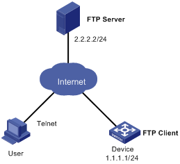
As shown in Figure 7, the current software version is soft-version1. The newest applications soft-version2.bin is saved under the aaa directory of the FTP server. The device and FTP server can reach each other, and the user and device can reach each other.
Remotely upgrade the software version of Device to soft-version2.

Upgrade procedure
1. Configure the FTP server (configuration varies with servers):
# Enable the FTP server.
<FTP-Server> system-view
[FTP-Server] ftp server enable
# Set the FTP username to aaa and password to hello.
[FTP-Server] local-user aaa
[FTP-Server-luser-aaa] password cipher hello
# Assign the FTP user the right to access the aaa directory.
[FTP-Server-luser-aaa] service-type ftp
[FTP-Server-luser-aaa] authorization-attribute work-directory flash:/aaa
2. Configure the device:
# Examine the free space of the Flash on the switch for memory insufficiency. If the free space is not sufficient for the new application programs, delete unused files from the Flash. (Details not shown.)
# Execute the save command to save the current configuration. (Details not shown.)
# Log in to the FTP server.
<Device> ftp 2.2.2.2
Trying 2.2.2.2 ...
Press CTRL+K to abort
Connected to 2.2.2.2.
220 WFTPD 2.0 service (by Texas Imperial Software) ready for new user
User(2.2.2.2:(none)):aaa
331 Give me your password, please
Password:
230 Logged in successfully
[ftp]
# Download the soft-version2.bin program from FTP server to the active MPU.
[ftp] binary
[ftp] get soft-version2.bin
[ftp] bye
<Device>
# Specify the main startup system software image on the active MPU.
<Device> boot-loader file soft-version2.bin slot 0 main
# Copy the image from the active MPU to the standby MPU.
<Device> copy soft-version2.bin slot1#flash:/soft-version2.bin
# Specify the image as the main startup system software image on the standby MPU.
<Device> boot-loader file slot1#flash:/soft-version2.bin slot 1 main
# Reboot the device to complete the upgrade.
<Device> reboot
3. Use the display version command to verify the upgrade.
System software image upgrade example (in IRF mode)
Network requirements
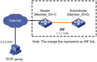
The IRF fabric in Figure 8 has two member switches: the master with the member ID 1 and the subordinate switch with the member ID 2. Each member has an active MPU in slot 0 and a standby MPU in slot 1. The current software version is soft-version1 for the IRF fabric. The latest application soft-version2.bin and the latest configuration file new-config.cfg are both saved on the TFTP server. The TFTP server and the IRF fabric can reach each other.
Upgrade the software version of the IRF fabric to soft-version2 and configuration file to new-config.
Upgrade procedure
1. Configure the TFTP server. (Details not shown.)
2. Configure the IRF member switches:
# Download new-config.cfg from the TFTP server to the active MPU of the master.
<IRF> tftp 2.2.2.2 get new-config.cfg
..
File will be transferred in binary mode
Downloading file from remote TFTP server, please wait.....
TFTP: 917 bytes received in 1 second(s)
File downloaded successfully.
<IRF> copy new-config.cfg chassis1#slot1#flash:/new-config.cfg
# Download new-config.cfg to the active MPU of the subordinate switch.
<IRF> copy new-config.cfg chassis2#slot0#flash:/new-config.cfg
<IRF> copy new-config.cfg chassis2#slot1#flash:/new-config.cfg
# Download soft-version2.bin from the TFTP server to the master and subordinate switches.
<IRF> tftp 2.2.2.2 get soft-version2.bin
...
File will be transferred in binary mode
Downloading file from remote TFTP server, please wait............
TFTP: 10058752 bytes received in 141 second(s)
File downloaded successfully.
<IRF> copy soft-version2.bin chassis1#slot1#flash:/soft-version2.bin
<IRF> copy soft-version2.bin chassis2#slot0#flash:/soft-version2.bin
<IRF> copy soft-version2.bin chassis2#slot1#flash:/soft-version2.bin
# Specify new-config.cfg as the next-startup configuration file for all member switches of the IRF fabric.
<IRF> startup saved-configuration flash:/new-config.cfg
Please wait ...
Setting the master board ...
... Done!
Setting the slave board ...
Chassis 1 Slot 1:
Set next configuration file successfully.
Chassis 2 Slot 0:
Set next configuration file successfully.
Chassis 2 Slot 1:
Set next configuration file successfully.
# Specify soft-version2.bin as the startup system software image for all MPUs.
<IRF> boot-loader file flash:/soft-version2.bin chassis 1 slot 0 main
This command will set the boot file of the specified board. Continue? [Y/N]:y
The specified file will be used as the main boot file at the next reboot on chassis 1 slot 0!
<IRF> boot-loader file chassis1#slot1#flash:/soft-version2.bin chassis 1 slot 1 main
This command will set the boot file of the specified board. Continue? [Y/N]:y
The specified file will be used as the main boot file at the next reboot on chassis 1 slot 1!
<IRF> boot-loader file chassis2#slot0#flash:/soft-version2.bin chassis 2 slot 0 main
This command will set the boot file of the specified board. Continue? [Y/N]:y
The specified file will be used as the main boot file at the next reboot on chassis 2 slot 0!
<IRF> boot-loader file chassis2#slot1#flash:/soft-version2.bin chassis 2 slot 1 main
This command will set the boot file of the specified board. Continue? [Y/N]:y
The specified file will be used as the main boot file at the next reboot on chassis 2 slot 1!
# Reboot the device to complete the upgrade.
<IRF> reboot
3. Use the display version command to verify the upgrade. (Details not shown.)
Scheduled upgrade configuration example
Network requirement
The device in Figure 9 is running the system software version soft-version1. Download the latest software file soft-version2.bin from the aaa directory of the FTP server for an software upgrade.
Configuration procedure
This example assumes that the device and the FTP server can reach each other, and the user and the device can reach each other.
1. Configure the FTP server (configuration varies with servers):
# Enable the FTP server.
<FTP-Server> system-view
[FTP-Server] ftp server enable
# Set the FTP username to aaa and password to hello.
[FTP-Server] local-user aaa
[FTP-Server-luser-aaa] password cipher hello
# Assign the FTP user the right to access the flash:/aaa directory.
[FTP-Server-luser-aaa] service-type ftp
[FTP-Server-luser-aaa] work-directory flash:/aaa
Use text editor on the FTP server to edit batch file auto-update.txt. The following is the content of the batch file:
return
boot-loader file soft-version2.bin slot 0 main
boot-loader file slot1#flash:/soft-version2.bin slot 1 main
save
reboot
2. Configure the device:
# Examine the free space of the Flash on the switch for memory insufficiency. If the free space is not sufficient for the new application programs, delete unused files from the Flash. (Details not shown.)
# Execute the save command to save the current configuration. (Details not shown.)
# Log in to FTP Server. (The prompt might vary with servers.)
<Device> ftp 2.2.2.2
Trying 2.2.2.2 ...
Press CTRL+K to abort
Connected to 2.2.2.2.
220 WFTPD 2.0 service (by Texas Imperial Software) ready for new user
User(2.2.2.2:(none)):aaa
331 Give me your password, please
Password:
230 Logged in successfully
[ftp]
# Download soft-version2.bin from the FTP server.
[ftp] binary
[ftp] get soft-version2.bin
[ftp] bye
<Device>
# Change the extension of file auto-update.txt to .bat.
<Device> rename auto-update.txt auto-update.bat
To ensure correctness of the file, you can use the more command to view the content of the file.
<Device> more flash:/auto-update.txt
return
boot-loader file soft-version2.bin slot 0 main
boot-loader file slot1#flash:/soft-version2.bin slot 1 main
save
reboot
# Specify soft-version2.bin as the startup system software image for all MPUs. Execute the scheduled automatic execution function to enable the device to be automatically upgraded at 1 am June 21st, 2010. (Slot number of the active MPU is 0, and that of the standby MPU is 1.)
<Device> copy soft-version2.bin slot1#flash:/soft-version2.bin
<Device> schedule job at 01:00 2010/6/21 view system execute auto-update.bat
3. Use the display version command to verify the upgrade.
Hotfix configuration example
Network requirements
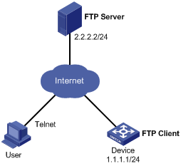
The software running on the device is of some problem. The patch file patch_mr.bin is saved under the directory aaa of the FTP server. An available route exists between Device and FTP server. User is allowed to Telnet to Device, and User and Device can reach each other.
Use FTP to download the patch files and then hotfix the software on the device.
Figure 10 Network diagram
Configuration procedure
1. Configure the FTP server:
# Enable the FTP server.
<FTP-Server> system-view
[FTP-Server] ftp server enable
# Set the FTP username to aaa and password to hello.
[FTP-Server] local-user aaa
[FTP-Server-luser-aaa] password cipher hello
# Assign the FTP user the right to access the aaa directory.
[FTP-Server-luser-aaa] service-type ftp
[FTP-Server-luser-aaa] authorization-attribute work-directory flash:/aaa
2. Configure the device (FTP client):
# Examine the free space of the Flash on the switch for memory insufficiency. If the free space is not sufficient for the patch file, delete old unused files from the Flash. (Details not shown.)
# Use the save command to save the running configuration. (Details not shown.)
# Log in to the FTP server.
<Device> ftp 2.2.2.2
Trying 2.2.2.2 ...
Press CTRL+K to abort
Connected to 2.2.2.2.
220 WFTPD 2.0 service (by Texas Imperial Software) ready for new user
User(2.2.2.2:(none)):aaa
331 Give me your password, please
Password:
230 Logged in successfully
[ftp]
# Download the file patch_mr.bin from the FTP server.
[ftp] binary
[ftp] get patch_mr.bin
[ftp] bye
<Device>
# Copy the patch file to the root directory of the standby MPU in slot 1.
<Device> copy patch_mr.bin slot1#flash:/
# Install patches.
<Device> system-view
[Device] patch install flash:
Patches will be installed. Continue? [Y/N]:y
Do you want to continue running patches after reboot? [Y/N]:y
Installing patches........
Installation completed, and patches will continue to run after reboot.
