- Table of Contents
-
- 12-High Availability Configuration Guide
- 00-Preface
- 01-High Availability Overview
- 02-Active and Standby Switchover Configuration
- 03-Ethernet OAM Configuration
- 04-CFD Configuration
- 05-DLDP Configuration
- 06-RPR Configuration
- 07-RRPP Configuration
- 08-Smart Link Configuration
- 09-Monitor Link Configuration
- 10-VRRP Configuration
- 11-BFD Configuration
- 12-Track Configuration
- Related Documents
-
| Title | Size | Download |
|---|---|---|
| 07-RRPP Configuration | 508.1 KB |
Contents
Configuring RRPP fast detection
Configuring fast detection timers
Configuring an RRPP ring group
Displaying and maintaining RRPP
Single ring configuration example
Intersecting ring configuration example
Dual homed rings configuration example
Intersecting-ring load balancing configuration example
Fast detection configuration example
RRPP overview
The Rapid Ring Protection Protocol (RRPP) is a link layer protocol designed for Ethernet rings. RRPP can prevent broadcast storms caused by data loops when an Ethernet ring is healthy, and rapidly restore the communication paths between the nodes in the event that a link is disconnected on the ring.
Metropolitan area networks (MANs) and enterprise networks typically use the ring structure to improve reliability. However, services will be interrupted if any node in the ring network fails. A ring network usually uses Resilient Packet Ring (RPR) or Ethernet rings. RPR is high in cost as it needs dedicated hardware. In contrast, the Ethernet ring technology is more mature and economical, so it is more and more widely used in MANs and enterprise networks.
Rapid Spanning Tree Protocol (RSTP), Per VLAN Spanning Tree (PVST), Multiple Spanning Tree Protocol (MSTP), and RRPP can eliminate Layer-2 loops. RSTP, PVST, and MSTP are mature, but they take several seconds to converge. RRPP is an Ethernet ring-specific data link layer protocol, and converges faster than RSTP, PVST, and MSTP. Additionally, the convergence time of RRPP is independent of the number of nodes in the Ethernet ring. RRPP can be applied to large-diameter networks.
Basic concepts in RRPP
RRPP domain
The interconnected devices with the same domain ID and control VLANs constitute an RRPP domain. The major elements of an RRPP domain includes the primary ring, subring, control VLAN, master node, transit node, primary port, secondary port, common port, and edge port.
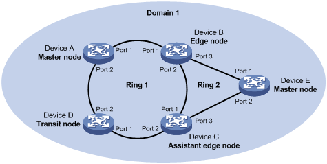
As shown in Figure 1, Domain 1 is an RRPP domain, including two RRPP rings: Ring 1 and Ring 2. All the nodes on the two RRPP rings belong to the RRPP domain.
RRPP ring
A ring-shaped Ethernet topology is called an "RRPP ring". RRPP rings fall into the following types: primary ring and subring. You can configure a ring as either the primary ring or a subring by specifying its ring level. The primary ring is of level 0, and a subring is of level 1. An RRPP domain contains one or multiple RRPP rings, one serving as the primary ring and the others serving as subrings. A ring can be in one of the following states:
· Health state—All the physical links on the Ethernet ring are connected
· Disconnect state—Some physical links on the Ethernet ring are broken
As shown in Figure 1, Domain 1 contains two RRPP rings: Ring 1 and Ring 2. The level of Ring 1 is set to 0, and that of Ring 2 is set to 1. Ring 1 is configured as the primary ring, and Ring 2 is configured as a subring.
Control VLAN and data VLAN
1. Control VLAN
In an RRPP domain, a control VLAN is a VLAN dedicated to transferring RRPP data units (RRPPDUs). On a device, the ports accessing an RRPP ring belong to the control VLANs of the ring, and only such ports can join the control VLANs.
An RRPP domain is configured with two control VLANs: one primary control VLAN, which is the control VLAN for the primary ring; one secondary control VLAN, which is the control VLAN for subrings. All subrings in the same RRPP domain share the same secondary control VLAN. After you specify a VLAN as the primary control VLAN, the system automatically configures the VLAN whose ID is the primary control VLAN ID plus one as the secondary control VLAN.
IP address configuration is prohibited on the control VLAN interfaces.
2. Data VLAN
A data VLAN is a VLAN dedicated to transferring data packets. Both RRPP ports and non-RRPP ports can be assigned to a data VLAN.
Node
Each device on an RRPP ring is a node. The role of a node is configurable. RRPP has the following node roles:
· Master node—Each ring has one and only one master node. The master node initiates the polling mechanism and determines the operations to be performed after a change in topology.
· Transit node—Transit nodes include all nodes except the master node on the primary ring and all nodes on subrings except the master nodes and the nodes where the primary ring intersects with the subrings. A transit node monitors the state of its directly-connected RRPP links and notifies the master node of the link state changes, if any. Based on the link state changes, the master node decides the operations to be performed.
· Edge node—A node residing on both the primary ring and a subring at the same time. An edge node is a special transit node that serves as a transit node on the primary ring and an edge node on the subring.
· Assistant-edge node—A node residing on both the primary ring and a subring at the same time. An assistant-edge node is a special transit node that serves as a transit node on the primary ring and an assistant-edge node on the subring. This node works in conjunction with the edge node to detect the integrity of the primary ring and perform loop guard.
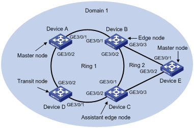
As shown in Figure 1, Ring 1 is the primary ring and Ring 2 is a subring. Device A is the master node of Ring 1, Device B, Device C and Device D are the transit nodes of Ring 1. Device E is the master node of Ring 2, Device B is the edge node of Ring 2, and Device C is the assistant-edge node of Ring 2.
Primary port and secondary port
Each master node or transit node has two ports connected to an RRPP ring, one serving as the primary port and the other serving as the secondary port. You can determine the role of a port.
1. In terms of functionality, the primary port and the secondary port of a master node have the following differences:
¡ The primary port and the secondary port are designed to play the role of sending and receiving loop-detect packets, respectively.
¡ When an RRPP ring is in Health state, the secondary port of the master node will logically deny data VLANs and permit only the packets from the control VLANs.
¡ When an RRPP ring is in Disconnect state, the secondary port of the master node will forward packets from data VLANs.
2. In terms of functionality, the primary port and the secondary port of a transit node are the same. Both are designed for transferring protocol packets and data packets over an RRPP ring.
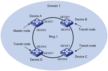
As shown in Figure 1, Device A is the master node of Ring 1. Port 1 and Port 2 are the primary port and the secondary port of the master node on Ring 1, respectively. Device B, Device C, and Device D are the transit nodes of Ring 1. Their Port 1 and Port 2 are the primary port and the secondary port on Ring 1, respectively.
Common port and edge port
The ports connecting the edge node and assistant-edge node to the primary ring are common ports. The ports connecting the edge node and assistant-edge node only to the subrings are edge ports.
As shown in Figure 1, Device B and Device C lie on Ring 1 and Ring 2. Device B’s Port 1 and Port 2 and Device C’s Port 1 and Port 2 access the primary ring, so they are common ports. Device B’s Port 3 and Device C’s Port 3 access only the subring, so they are edge ports.
RRPP ring group
To reduce Edge-Hello traffic, you can configure a group of subrings on the edge node or assistant-edge node. For more information about Edge-Hello packets, see "RRPPDUS." You must configure a device as the edge node of these subrings, and another device as the assistant-edge node of these subrings. Additionally, the subrings of the edge node and assistant-edge node must connect to the same subring packet tunnels in major ring (SRPTs), so that Edge-Hello packets of the edge node of these subrings travel to the assistant-edge node of these subrings over the same link.
An RRPP ring group configured on the edge node is an edge node RRPP ring group, and an RRPP ring group configured on an assistant-edge node is an assistant-edge node RRPP ring group. Up to one subring in an edge node RRPP ring group is allowed to send Edge-Hello packets.
RRPPDUS
Table 1 RRPPDU types and their functions
|
Type |
Description |
|
Hello |
The master node initiates Hello packets to detect the integrity of a ring in a network. |
|
Fast-Hello |
The master node initiates Fast-Hello packets to fast detect the integrity of a ring in a network. |
|
Link-Down |
The transit node, the edge node or the assistant-edge node initiates Link-Down packets to notify the master node of the disappearance of a ring in case of a link failure. |
|
Common-Flush-FDB |
The master node initiates Common-Flush-FDB (FDB stands for Forwarding Database) packets to instruct the transit nodes to update their own MAC entries and ARP/ND entries when an RRPP ring transits to Disconnect state. |
|
Complete-Flush-FDB |
The master node initiates Complete-Flush-FDB packets to instruct the transit nodes to update their own MAC entries and ARP/ND entries, and release blocked ports from being blocked temporarily when an RRPP ring transits to Health state. |
|
Edge-Hello |
The edge node initiates Edge-Hello packets to examine the SRPTs between the edge node and the assistant-edge node. |
|
Fast-Edge-Hello |
The edge node initiates Fast-Edge-Hello packets to fast examine the SRPTs between it and the assistant-edge node. |
|
Major-Fault |
The assistant-edge node initiates Major-Fault packets to notify the edge node of SRPT failure when an SRPT between edge node and assistant-edge node is torn down. |
|
|
NOTE: RRPPDUs of subrings are transmitted as data packets in the primary ring, and RRPPDUs of the primary ring can only be transmitted within the primary ring. |
RRPP timers
When RRPP checks the link state of an Ethernet ring, the master node sends Hello packets out the primary port according to the Hello timer and determines whether its secondary port receives the Hello packets based on the Fail timer.
· The Hello timer specifies the interval at which the master node sends Hello packets out the primary port.
· The Fail timer specifies the maximum delay between the master node sending Hello packets out the primary port and the secondary port receiving the Hello packets from the primary port. If the secondary port receives the Hello packets sent by the local master node before the Fail timer expires, the overall ring is in Health state. Otherwise, the ring transits into Disconnect state.
· The Fast-Hello timer specifies the interval at which the master node sends Fast-Hello packets out the primary port.
· The Fast-Fail timer specifies the maximum delay between the master node sending Fast-Hello packets out the primary port and the secondary port receiving the Fast-Hello packets from the primary port. If the secondary port receives the Fast-Hello packets sent by the local master node before the Fast-Fail timer expires, the entire ring is in Health state. Otherwise, the ring transits into the Disconnect state.
|
|
NOTE: · In an RRPP domain, a transit node learns the Hello timer value and the Fail timer value on the master node through the received Hello packets, making sure that all nodes in the ring network are consistent in the two timer settings. A transit node, however, cannot learn the Fast-Hello timer value and the Fast-Fail timer value set on the master node through received Fast-Hello packets. · Only the main processing units (MPUs) suffixed with C and D (LSR1SRP2C1, for example) support the RRPP fast detection mechanism. The MPUs suffixed with B (LSR1SRP2B1, for example) do not support this mechanism. |
How RRPP works
Polling mechanism
The polling mechanism is used by the master node of an RRPP ring to check the Health state of the ring network.
The master node sends Hello packets out its primary port periodically, and these Hello packets travel through each transit node on the ring in turn.
· If the ring is complete, the secondary port of the master node will receive Hello packets before the Fail timer expires and the master node will keep the secondary port blocked.
· If the ring is torn down, the secondary port of the master node will fail to receive Hello packets before the Fail timer expires. The master node will release the secondary port from blocking data VLANs and sending Common-Flush-FDB packets to instruct all transit nodes to update their own MAC entries and ARP/ND entries.
Link down alarm mechanism
The transit node, the edge node or the assistant-edge node sends Link-Down packets to the master node immediately when they find any of its own ports belonging to an RRPP domain is down. Upon the receipt of a Link-Down packet, the master node releases the secondary port from blocking data VLANs and sending Common-Flush-FDB packet to instruct all the transit nodes, the edge nodes and the assistant-edge nodes to update their own MAC entries and ARP/ND entries. After each node updates its own entries, traffic is switched to the normal link.
Ring recovery
The master node may find the ring is restored after a period of time after the ports belonging to the RRPP domain on the transit nodes, the edge nodes, or the assistant-edge nodes are brought up again. A temporary loop may arise in the data VLAN during this period. As a result, broadcast storm occurs.
To prevent temporary loops, non-master nodes block them immediately (and permit only the packets from the control VLAN to pass through) when they find their ports accessing the ring are brought up again. The blocked ports are activated only when the nodes are sure that no loop will be generated by these ports.
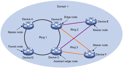
Broadcast storm suppression mechanism in case of SRPT failure in a multi-homed subring
As shown in Figure 5, Ring 1 is the primary ring, and Ring 2 and Ring 3 are subrings. When the two SRPTs between the edge node and the assistant-edge node are down, the master nodes of Ring 2 and Ring 3 will open their respective secondary ports, generating a loop among Device B, Device C, Device E, and Device F and causing a broadcast storm.
To prevent generating a loop, the edge node will temporarily block the edge port. The blocked edge port is activated only when the edge node is sure that no loop will be generated when the edge port is activated.
Load balancing
In a ring network, traffic from multiple VLANs may be transmitted at the same time. RRPP can implement load balancing for the traffic by transmitting traffic from different VLANs along different paths.
By configuring an individual RRPP domain for transmitting the traffic from the specified VLANs (protected VLANs) in a ring network, traffic from different VLANs can be transmitted according to different topologies in the ring network for load balancing.
As shown in Figure 6, Ring 1 is configured as the primary ring of Domain 1 and Domain 2, which are configured with different protected VLANs. Device A is the master node of Ring 1 in Domain 1; Device B is the master node of Ring 1 in Domain 2. With such configurations, traffic from different VLANs can be transmitted on different links for load balancing in the single-ring network.
RRPP ring group
In an edge node RRPP ring group, only an activated subring with the lowest domain ID and ring ID can send Edge-Hello packets. In an assistant-edge node RRPP ring group, any activated subring that has received Edge-Hello packets will forward these packets to the other activated subrings. With an edge node RRPP ring group and an assistant-edge node RRPP ring group configured, only one subring sends Edge-Hello packets on the edge node, and only one subring receives Edge-Hello packets on the assistant-edge node, reducing CPU workload.
As shown in Figure 5, Device B is the edge node of Ring 2 and Ring 3, and Device C is the assistant-edge node of Ring 2 and Ring 3. Device B and Device C need to send or receive Edge-Hello packets frequently. If more subrings are configured or load balancing is configured for more multiple domains, Device B and Device C will send or receive a mass of Edge-Hello packets.
To reduce Edge-Hello traffic, you can assign Ring 2 and Ring 3 to an RRPP ring group configured on the edge node Device B, and assign Ring 2 and Ring 3 to an RRPP ring group configured on Device C. After such configurations, if all rings are activated, only Ring 2 on Device B sends Edge-Hello packets.
Fast detection mechanism
Ideally, an RRPP ring can fast converge because its transit nodes can detect link failures fast and send out notifications immediately. In practice, some devices on an RRPP ring may not support RRPP. RRPP can detect link failures between these devices only through the timeout mechanism. This results in long-time traffic interruption and failure to implement millisecond-level convergence.
To address this problem, a fast detection mechanism was introduced. The mechanism works as follows:
· The master node sends Fast-Hello packets out its primary port at the interval specified by the Fast-Hello timer. If the secondary port receives the Fast-Hello packets sent by the local master node before the Fast-Fail timer expires, the entire ring is in Health state; otherwise, the ring transits into the Disconnect state.
· The edge node sends Fast-Edge-Hello packets out its common ports at the interval specified by the timer resolution. If the assistant-edge node fails to receive the Fast-Edge-Hello packets within three times the timer resolution, the SRPTs transit to Disconnect state.
As shown in Figure 2, with fast detection enabled for RRPP domain 1, Device A, the master node of Ring 1, sends out Fast-Hello packets periodically and determines the ring status according to whether Fast-Hello packets are received before the Fast-Fail timer expires, implementing link status fast detection.
|
|
NOTE: · Timer resolution refers to the shortest-period timer provided on an RRPP node, which is 10 milliseconds on the switch. · To implement fast detection on an RRPP ring, enable fast detection on the master node, edge node, and assistant-edge node of the RRPP ring. |
Typical RRPP networking
This section lists the following typical networking applications:
· Intersecting-ring load balancing
Single ring
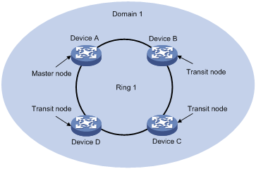
As shown in Figure 2, only a single ring exists in the network topology. You only need to define an RRPP domain.
Figure 2 Schematic diagram for a single-ring network
Tangent rings
As shown in Figure 3, two or more rings are in the network topology and only one common node exists between rings. You must define an RRPP domain for each ring.
Figure 3 Schematic diagram for a tangent-ring network
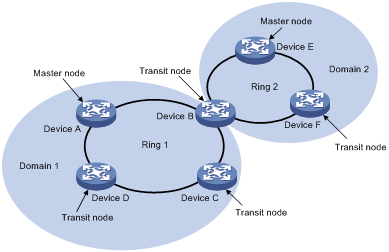
Intersecting rings
As shown in Figure 4, two or more rings are in the network topology and two common nodes exist between rings. You only need to define an RRPP domain, and configure one ring as the primary ring and the other rings as subrings.
Figure 4 Schematic diagram for an intersecting-ring network

Dual homed rings
As shown in Figure 5, two or more rings are in the network topology and two similar common nodes exist between rings. You only need to define an RRPP domain, and configure one ring as the primary ring and the other rings as subrings.
Figure 5 Schematic diagram for a dual-homed-ring network
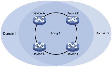
Single-ring load balancing
In a single-ring network, you can achieve load balancing by configuring multiple domains.
As shown in Figure 6, Ring 1 is configured as the primary ring of both Domain 1 and Domain 2. Domain 1 and Domain 2 are configured with different protected VLANs. In Domain 1, Device A is configured as the master node of Ring 1; in Domain 2, Device B is configured as the master node of Ring 1. Such configurations enable the ring to block different links based on VLANs and achieve single-ring load balancing.
Figure 6 Schematic diagram for a single-ring load balancing network
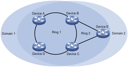
Intersecting-ring load balancing
As shown in Figure 7, Ring 1 is the primary ring and Ring 2 is the subring in both Domain 1 and Domain 2. Domain 1 and Domain 2 are configured with different protected VLANs. Device A is configured as the master node of Ring 1 in Domain 1; Device D is configured as the master node of Ring 1 in Domain 2. Device E is configured as the master node of Ring 2 in both Domain 1 and Domain 2. However, different ports on Device E are blocked in Domain 1 and Domain 2. With the configurations, you can enable traffic from different VLANs to travel over different paths in the subring and primary ring, achieving intersecting-ring load balancing.
Figure 7 Schematic diagram for an intersecting-ring load balancing network
Protocols and standards
RFC 3619, Extreme Networks' Ethernet Automatic Protection Switching (EAPS) Version 1 is related to RRPP.
RRPP configuration task list
You can create RRPP domains based on service planning, specify control VLANs and data VLANs for each RRPP domain, and then determine the ring roles and node roles based on the traffic paths in each RRPP domain.
Complete the following tasks to configure RRPP:
|
Task |
Remarks |
|
|
Required. Perform this task on all nodes in the RRPP domain. |
||
|
Required. Perform this task on all nodes in the RRPP domain. |
||
|
Required. Perform this task on all nodes in the RRPP domain. |
||
|
Required. Perform this task on all nodes in the RRPP domain. |
||
|
Required. Perform this task on all nodes in the RRPP domain |
||
|
Required. Perform this task on all nodes in the RRPP domain. |
||
|
Optional. Perform this task on the master node in the RRPP domain. |
||
|
Optional. Perform this task on the master node, edge node, and assistant-edge node in the RRPP domain. |
||
|
Optional. Perform this task on the master node in the RRPP domain. |
||
|
Optional. Perform this task on the edge node and assistant-edge node in the RRPP domain. |
||
|
|
NOTE: · RRPP does not have an auto election mechanism, so you must configure each node in the ring network properly for RRPP to monitor and protect the ring network. · Before configuring RRPP, you must construct a ring-shaped Ethernet topology physically. |
Creating an RRPP domain
When creating an RRPP domain, specify a domain ID, which uniquely identifies an RRPP domain. All devices in the same RRPP domain must be configured with the same domain ID.
Make this configuration on devices you want to configure as nodes in the RRPP domain.
To create an RRPP domain:
|
Step |
Command |
|
1. Enter system view. |
system-view |
|
2. Create an RRPP domain and enter RRPP domain view. |
rrpp domain domain-id |
Configuring control VLANs
Before configuring RRPP rings in an RRPP domain, configure the same control VLANs for all nodes in the RRPP domain first.
Perform this configuration on all nodes in the RRPP domain to be configured.
To configure control VLANs:
|
Step |
Command |
|
1. Enter system view. |
system-view |
|
2. Enter RRPP domain view. |
rrpp domain domain-id |
|
3. Configure the primary control VLAN for the RRPP domain. |
control-vlan vlan-id |
|
|
NOTE: · When you configure existing VLANs as control VLANs, the system prompts errors. · To ensure proper forwarding of RRPPDUs, do not enable 802.1Q in 802.1Q (QinQ) or VLAN mapping on the control VLANs. · To make sure that RRPPDUs can be sent and received correctly, do not configure the default VLAN of a port accessing an RRPP ring as the primary control VLAN or the secondary control VLAN. · To transparently transmit RRPPDUs on a device not configured with RRPP, you must make sure that only the two ports connecting the device to the RRPP ring permit packets from the control VLANs. Otherwise, the packets from other VLANs may enter the control VLANs in transparent transmission mode and strike the RRPP ring. |
Configuring protected VLANs
Before configuring RRPP rings in an RRPP domain, configure the same protected VLANs for all nodes in the RRPP domain first. All VLANs that the RRPP ports are assigned to should be protected by the RRPP domains.
You can configure protected VLANs through referencing Multiple Spanning Tree Instances (MSTIs). Before configuring protected VLANs, configure the mappings between MSTIs and the VLANs to be protected (a device working in PVST mode automatically maps VLANs to MSTIs). For more information about MSTIs and PVST, see Layer 2—LAN Switching Configuration Guide.
Perform this configuration on all nodes in the RRPP domain to be configured.
To configure protected VLANs:
|
Step |
Command |
Remarks |
|
1. Enter system view. |
system-view |
N/A |
|
2. Enter MST region view. |
stp region-configuration |
Not required if the device works in PVST mode. |
|
3. Configure the VLAN-to-instance mapping table. |
·
Approach 1: ·
Approach 2: |
Optional. Use either approach. All VLANs in an MST region are mapped to MSTI 0 (the CIST) by default. Not required if the device works in PVST mode. |
|
4. Activate MST region configuration manually. |
active region-configuration |
Required Not required if the device works in PVST mode. |
|
5. Display the currently activated configuration information of the MST region. |
display stp region-configuration [ | { begin | exclude | include } regular-expression ] |
Optional Available in any view. The output of the command includes VLAN-to-instance mappings. |
|
6. Return to system view. |
quit |
Not required if the device works in PVST mode. |
|
7. Enter RRPP domain view. |
rrpp domain domain-id |
N/A |
|
8. Configure protected VLANs for the RRPP domain. |
protected-vlan reference-instance instance-id-list |
Required By default, no protected VLAN is configured for an RRPP domain. |
|
|
NOTE: · When configuring load balancing, you must configure different protected VLANs for different RRPP domains. · For more information about the stp region-configuration, instance, vlan-mapping modulo, active region-configuration, and display stp region-configuration commands, see Layer 2—LAN Switching Command Reference. |
Configuring RRPP rings
When configuring an RRPP ring, you must make some configurations on the ports connecting each node to the RRPP ring before configuring the nodes.
|
|
NOTE: · RRPP ports (connecting devices to an RRPP ring) must be Layer-2 Ethernet ports, Layer-2 GE ports, Layer-2 XGE ports, or Layer-2 aggregate interfaces and cannot be member ports of any aggregation group or smart link group. · After configuring a Layer-2 aggregate interface as an RRPP port, you can still assign ports to or remove ports from the aggregation group corresponding to the interface. |
Configuring RRPP ports
Perform this configuration on each node’s ports intended for accessing RRPP rings.
To configure RRPP ports:
|
Step |
Command |
Remarks |
|
1. Enter system view. |
system-view |
N/A |
|
2. Enter interface view. |
interface interface-type interface-number |
N/A |
|
3. Configure the link type of the interface as trunk. |
port link-type trunk |
Access by default. |
|
4. Assign the trunk port to the protected VLANs of the RRPP domain. |
port trunk permit vlan { vlan-id-list | all } |
By default, a trunk port allows only packets from VLAN 1 to pass through. |
|
5. Disable the spanning tree feature. |
undo stp enable |
Enabled by default. |
|
|
NOTE: · RRPP ports always allow packets from the control VLANs to pass through. · For more information about the port link-type trunk, port trunk permit vlan, and undo stp enable commands, see Layer 2—LAN Switching Command Reference. · Do not enable OAM remote loopback function on an RRPP port. Otherwise, it may cause temporary broadcast storms. · H3C recommends using the link-delay command to enable link status rapid report function on an RRPP port by setting the physical state change suppression interval to 0 seconds, thus accelerating topology convergence. For more information about the link-delay command (or the undo link-delay command), see Interface Command Reference. |
Configuring RRPP nodes
|
|
NOTE: · The maximum number of rings that can be configured on a switch in all RRPP domains is 32 in total. · If a switch carries multiple RRPP rings in an RRPP domain, only one ring can be configured as the primary ring on the device and the role of the device on a subring can only be an edge node or an assistant-edge node. |
Specifying a master node
Perform this configuration on a device to be configured as a master node.
To specify a master node:
|
Step |
Command |
|
1. Enter system view. |
system-view |
|
2. Enter RRPP domain view. |
rrpp domain domain-id |
|
3. Specify the current device as the master node of the ring, and specify the primary port and the secondary port. |
ring ring-id node-mode master [ primary-port interface-type interface-number ] [ secondary-port interface-type interface-number ] level level-value |
Specifying a transit node
Perform this configuration on a device to be configured as a transit node.
To specify a transit node:
|
Step |
Command |
|
1. Enter system view. |
system-view |
|
2. Enter RRPP domain view. |
rrpp domain domain-id |
|
3. Specify the current device as a transit node of the ring, and specify the primary port and the secondary port. |
ring ring-id node-mode transit [ primary-port interface-type interface-number ] [ secondary-port interface-type interface-number ] level level-value |
Specifying an edge node
When configuring an edge node, you must first configure the primary ring before configuring the subrings.
Perform this configuration on a device to be configured as an edge node.
To specify an edge node:
|
Step |
Command |
|
1. Enter system view. |
system-view |
|
2. Enter RRPP domain view. |
rrpp domain domain-id |
|
3. Specify the current device as a transit node of the primary ring, and specify the primary port and the secondary port. |
ring ring-id node-mode transit [ primary-port interface-type interface-number ] [ secondary-port interface-type interface-number ] level level-value |
|
4. Specify the current device as the edge node of a subring, and specify the edge port. |
ring ring-id node-mode edge [ edge-port interface-type interface-number ] |
Specifying an assistant-edge node
When configuring an assistant-edge node, you must first configure the primary ring before configuring the subrings.
Perform this configuration on a device to be configured as an assistant-edge node.
To specify an assistant-edge node:
|
Step |
Command |
|
1. Enter system view. |
system-view |
|
2. Enter RRPP domain view. |
rrpp domain domain-id |
|
3. Specify the current device as a transit node of the primary ring, and specify the primary port and the secondary port. |
ring ring-id node-mode transit [ primary-port interface-type interface-number ] [ secondary-port interface-type interface-number ] level level-value |
|
4. Specify the current device as the assistant-edge node of the subring, and specify an edge port. |
ring ring-id node-mode assistant-edge [ edge-port interface-type interface-number ] |
Activating an RRPP domain
To activate an RRPP domain on the current device, enable the RRPP protocol and RRPP rings for the RRPP domain on the current device.
Perform this operation on all nodes in the RRPP domain.
To activate an RRPP domain:
|
Step |
Command |
Remarks |
|
1. Enter system view. |
system-view |
N/A |
|
2. Enable RRPP. |
rrpp enable |
Disabled by default |
|
3. Enter RRPP domain view. |
rrpp domain domain-id |
N/A |
|
4. Enable the specified RRPP ring. |
ring ring-id enable |
Disabled by default |
|
|
NOTE: To prevent Hello packets of subrings from being looped on the primary ring, enable the primary ring on its master node before enabling the subrings on their separate master nodes. On an edge node or assistant-edge node, enable/disable the primary ring and subrings separately: · Enable the primary ring of an RRPP domain before enabling the subrings of the RRPP domain. · Disable the primary ring of an RRPP domain after disabling all subrings of the RRPP domain. |
|
|
NOTE: After you enable enhanced IRF mode, the RRPP function is not supported. For more information about enhanced IRF mode, see IRF Configuration Guide. |
Configuring RRPP timers
Perform this configuration on the master node of an RRPP domain.
To configure RRPP timers:
|
Step |
Command |
Remarks |
|
1. Enter system view. |
system-view |
N/A |
|
2. Enter RRPP domain view. |
rrpp domain domain-id |
N/A |
|
3. Configure the Hello timer and Fail timer for the RRPP domain. |
timer hello-timer hello-value fail-timer fail-value |
By default, the Hello timer value is 1 second and the Fail timer value is 3 seconds. |
|
|
NOTE: · The Fail timer value must be equal to or greater than three times the Hello timer value. · To avoid temporary loops when the primary ring fails in a dual-homed-ring network, make sure that the difference between the Fail timer value on the master node of the subring and that on the master node of the primary ring is greater than twice the Hello timer value of the master node of the subring. |
Configuring RRPP fast detection
Enabling fast detection
Perform this configuration on the master node, edge node, and assistant-edge node in the RRPP domain to be configured.
To enable fast detection:
|
Step |
Command |
Remarks |
|
1. Enter system view. |
system-view |
N/A |
|
2. Enter RRPP domain view. |
rrpp domain domain-id |
N/A |
|
3. Enable fast detection. |
fast-detection enable |
Disabled by default |
|
|
NOTE: · To configure fast detection on the master node of a subring, make sure that the edge node and assistant-edge node of the subring support fast detection. Otherwise, do not configure fast detection on the master node of the subring. · When configuring fast detection in an RRPP domain, enable fast detection first on the edge node, and then on the assistant-edge node. Otherwise, the assistant-edge node may fail to receive Fast-Edge-Hello packets and erroneously conclude that the master node is faulty. · Only the MPUs suffixed with C and D (LSR1SRP2C1, for example) support the RRPP fast detection mechanism. The MPUs suffixed with B (LSR1SRP2B1, for example) do not support this mechanism. |
Configuring fast detection timers
Perform this configuration on the master node in the RRPP domain to be configured.
To configure RRPP fast detection timers:
|
Step |
Command |
Remarks |
|
1. Enter system view. |
system-view |
N/A |
|
2. Enter RRPP domain view. |
rrpp domain domain-id |
N/A |
|
3. Configure the Fast-Fail timer. |
timer fast-fail-timer fast-fail-value |
Optional. By default, the Fast-Fail timer is 60 milliseconds, six times the timer resolution supported by the switch. |
|
4. Configure the Fast-Hello timer. |
timer fast-hello-timer fast-hello-value |
Optional. By default, the Fast-Hello timer is 20 milliseconds, twice the timer resolution supported by the switch. |
|
|
NOTE: · The value of the Fast-Fail timer must be equal to or greater than three times the Fast-Hello timer. · In a dual-homed-ring network, to avoid temporary loops when the primary ring fails, make sure that the Fast-Fail timer value is equal to or greater than six times the timer resolution, and the difference between the Fast-Fail timer value on the master node of the subring and that on the master node of the primary ring is greater than twice the Fast-Hello timer value of the master node of the subring. |
Configuring an RRPP ring group
To reduce Edge-Hello traffic, adopt the RRPP ring group mechanism by assigning subrings with the same edge node/assistant-edge node to an RRPP ring group. An RRPP ring group must be configured on both the edge node and the assistant-edge node, and can only be configured on these two types of nodes.
Perform this configuration on both the edge node and the assistant-edge node in an RRPP domain.
To configure an RRPP ring group:
|
Step |
Command |
|
1. Enter system view. |
system-view |
|
2. Create an RRPP ring group and enter RRPP ring group view. |
rrpp ring-group ring-group-id |
|
3. Assign the specified subrings to the RRPP ring group. |
domain domain-id ring ring-id-list |
|
|
NOTE: · You can assign a subring to only one RRPP ring group. The RRPP ring group configured on the edge node and that configured on the assistant-edge node must contain the same subrings. Otherwise, the RRPP ring group cannot operate properly. · Make sure that the subrings in an RRPP ring group share the same edge node and assistant-edge node, and the edge node and the assistant edge node have the same SRPTs. · Make sure that a device plays the same role on the subrings in an RRPP ring group. The role can be the edge node or the assistant-edge node. · Make sure that the RRPP ring group on the edge node and that on the assistant-edge node have the same configurations and activation status. · Make sure that all subrings in an RRPP ring group have the same SRPTs. If the SRPTs of these subrings are configured or modified differently, the RRPP ring group cannot operate properly. |
Displaying and maintaining RRPP
|
Task |
Command |
Remarks |
|
Display brief RRPP information. |
display rrpp brief [ | { begin | exclude | include } regular-expression ] |
Available in any view |
|
Display RRPP group configuration information. |
display rrpp ring-group [ ring-group-id ] [ | { begin | exclude | include } regular-expression ] |
Available in any view |
|
Display detailed RRPP information. |
display rrpp verbose domain domain-id [ ring ring-id ] [ | { begin | exclude | include } regular-expression ] |
Available in any view |
|
Display RRPP statistics. |
display rrpp statistics domain domain-id [ ring ring-id ] [ | { begin | exclude | include } regular-expression ] |
Available in any view |
|
Clear RRPP statistics. |
reset rrpp statistics domain domain-id [ ring ring-id ] |
Available in user view |
RRPP configuration examples
|
|
NOTE: By default, Ethernet, VLAN, and aggregate interfaces are in DOWN state. Before configuring these interfaces, use the undo shutdown command to bring them up. |
Single ring configuration example
Networking requirements
As shown in Figure 8,
· Device A, Device B, Device C, and Device D form RRPP domain 1. Specify the primary control VLAN of RRPP domain 1 as VLAN 4092, and specify that RRPP domain 1 protects VLANs 1 through 30.
· Device A, Device B, Device C and Device D form primary ring 1.
Specify Device A as the master node of primary ring 1, GigabitEthernet 3/0/1 as the primary port and GigabitEthernet 3/0/2 as the secondary port.
Specify Device B, Device C and Device D as the transit nodes of primary ring 1, their GigabitEthernet 3/0/1 as the primary port and GigabitEthernet 3/0/2 as the secondary port.
Configuration procedure
1. Configure Device A.
# Create VLANs 1 through 30, map these VLANs to MSTI 1, and activate the MST region configuration.
<DeviceA> system-view
[DeviceA] vlan 1 to 30
[DeviceA] stp region-configuration
[DeviceA-mst-region] instance 1 vlan 1 to 30
[DeviceA-mst-region] active region-configuration
[DeviceA-mst-region] quit
# Set the physical state change suppression interval to 0 seconds on GigabitEthernet 3/0/1 and GigabitEthernet 3/0/2, disable the spanning tree feature, configure the two ports as trunk ports, and assign them to VLANs 1 through 30.
<DeviceA> system-view
[DeviceA] interface gigabitethernet 3/0/1
[DeviceA-GigabitEthernet3/0/1] link-delay 0
[DeviceA-GigabitEthernet3/0/1] undo stp enable
[DeviceA-GigabitEthernet3/0/1] port link-type trunk
[DeviceA-GigabitEthernet3/0/1] port trunk permit vlan 1 to 30
[DeviceA-GigabitEthernet3/0/1] quit
[DeviceA] interface gigabitethernet 3/0/2
[DeviceA-GigabitEthernet3/0/2] link-delay 0
[DeviceA-GigabitEthernet3/0/2] undo stp enable
[DeviceA-GigabitEthernet3/0/2] port link-type trunk
[DeviceA-GigabitEthernet3/0/2] port trunk permit vlan 1 to 30
[DeviceA-GigabitEthernet3/0/2] quit
# Create RRPP domain 1, configure VLAN 4092 as the primary control VLAN of RRPP domain 1, and configure the VLANs mapped to MSTI 1 as the protected VLANs of RRPP domain 1.
[DeviceA] rrpp domain 1
[DeviceA-rrpp-domain1] control-vlan 4092
[DeviceA-rrpp-domain1] protected-vlan reference-instance 1
# Configure Device A as the master node of primary ring 1, with GigabitEthernet 3/0/1 as the primary port and GigabitEthernet 3/0/2 as the secondary port, and enable ring 1.
[DeviceA-rrpp-domain1] ring 1 node-mode master primary-port gigabitethernet 3/0/1 secondary-port gigabitethernet 3/0/2 level 0
[DeviceA-rrpp-domain1] ring 1 enable
[DeviceA-rrpp-domain1] quit
# Enable RRPP.
[DeviceA] rrpp enable
2. Configure Device B.
# Create VLANs 1 through 30, map these VLANs to MSTI 1, and activate the MST region configuration.
<DeviceB> system-view
[DeviceB] vlan 1 to 30
[DeviceB] stp region-configuration
[DeviceB-mst-region] instance 1 vlan 1 to 30
[DeviceB-mst-region] active region-configuration
[DeviceB-mst-region] quit
# Set the physical state change suppression interval to 0 seconds on GigabitEthernet 3/0/1 and GigabitEthernet 3/0/2, disable the spanning tree feature, configure the two ports as trunk ports, and assign them to VLANs 1 through 30.
[DeviceB] interface gigabitethernet 3/0/1
[DeviceB-GigabitEthernet3/0/1] link-delay 0
[DeviceB-GigabitEthernet3/0/1] undo stp enable
[DeviceB-GigabitEthernet3/0/1] port link-type trunk
[DeviceB-GigabitEthernet3/0/1] port trunk permit vlan 1 to 30
[DeviceB-GigabitEthernet3/0/1] quit
[DeviceB] interface gigabitethernet 3/0/2
[DeviceB-GigabitEthernet3/0/2] link-delay 0
[DeviceB-GigabitEthernet3/0/2] undo stp enable
[DeviceB-GigabitEthernet3/0/2] port link-type trunk
[DeviceB-GigabitEthernet3/0/2] port trunk permit vlan 1 to 30
[DeviceB-GigabitEthernet3/0/2] quit
# Create RRPP domain 1, configure VLAN 4092 as the primary control VLAN of RRPP domain 1, and configure the VLANs mapped to MSTI 1 as the protected VLANs of RRPP domain 1.
[DeviceB] rrpp domain 1
[DeviceB-rrpp-domain1] control-vlan 4092
[DeviceB-rrpp-domain1] protected-vlan reference-instance 1
# Configure Device B as the transit node of primary ring 1, with GigabitEthernet 3/0/1 as the primary port and GigabitEthernet 3/0/2 as the secondary port, and enable ring 1.
[DeviceB-rrpp-domain1] ring 1 node-mode transit primary-port gigabitethernet 3/0/1 secondary-port gigabitethernet 3/0/2 level 0
[DeviceB-rrpp-domain1] ring 1 enable
[DeviceB-rrpp-domain1] quit
# Enable RRPP.
[DeviceB] rrpp enable
3. Configure Device C.
Configure Device C by using the same procedure as for configuring Device B.
4. Configure Device D.
Configure Device D by using the same procedure as for configuring Device B.
Use the display command to view RRPP configuration and operational information on each device.
Intersecting ring configuration example
Networking requirements
As shown in Figure 9,
· Device A, Device B, Device C, Device D, and Device E form RRPP domain 1, VLAN 4092 is the primary control VLAN of RRPP domain 1, and RRPP domain 1 protects VLANs 1 through 30.
· Device A, Device B, Device C and Device D form primary ring 1, and Device B, Device C and Device E form subring 2.
· Device A is the master node of primary ring 1, with GigabitEthernet 3/0/1 as the primary port and GigabitEthernet 3/0/2 the secondary port.
· Device E is the master node of subring 2, with GigabitEthernet 3/0/1 as the primary port and GigabitEthernet 3/0/2 the secondary port.
· Device B is the transit node of primary ring 1 and the edge node of subring 2, and GigabitEthernet 3/0/3 is the edge port.
· Device C is the transit node of primary ring 1 and the assistant-edge node of subring 1, and GigabitEthernet 3/0/3 is the edge port.
· Device D is the transit node of primary ring 1, with GigabitEthernet 3/0/1 as the primary port and GigabitEthernet 3/0/2 the secondary port.
Configuration procedure
1. Configure Device A.
# Create VLANs 1 through 30, map these VLANs to MSTI 1, and activate the MST region configuration.
<DeviceA> system-view
[DeviceA] vlan 1 to 30
[DeviceA] stp region-configuration
[DeviceA-mst-region] instance 1 vlan 1 to 30
[DeviceA-mst-region] active region-configuration
[DeviceA-mst-region] quit
# Set the physical state change suppression interval to 0 seconds on GigabitEthernet 3/0/1 and GigabitEthernet 3/0/2, disable the spanning tree feature, configure the two ports as trunk ports, and assign them to VLANs 1 through 30.
<DeviceA> system-view
[DeviceA] interface gigabitethernet 3/0/1
[DeviceA-GigabitEthernet3/0/1] link-delay 0
[DeviceA-GigabitEthernet3/0/1] undo stp enable
[DeviceA-GigabitEthernet3/0/1] port link-type trunk
[DeviceA-GigabitEthernet3/0/1] port trunk permit vlan 1 to 30
[DeviceA-GigabitEthernet3/0/1] quit
[DeviceA] interface gigabitethernet 3/0/2
[DeviceA-GigabitEthernet3/0/2] link-delay 0
[DeviceA-GigabitEthernet3/0/2] undo stp enable
[DeviceA-GigabitEthernet3/0/2] port link-type trunk
[DeviceA-GigabitEthernet3/0/2] port trunk permit vlan 1 to 30
[DeviceA-GigabitEthernet3/0/2] quit
# Create RRPP domain 1, configure VLAN 4092 as the primary control VLAN of RRPP domain 1, and configure the VLANs mapped to MSTI 1 as the protected VLANs of RRPP domain 1.
[DeviceA] rrpp domain 1
[DeviceA-rrpp-domain1] control-vlan 4092
[DeviceA-rrpp-domain1] protected-vlan reference-instance 1
# Configure Device A as the master node of primary ring 1, with GigabitEthernet 3/0/1 as the primary port and GigabitEthernet 3/0/2 as the secondary port, and enable ring 1.
[DeviceA-rrpp-domain1] ring 1 node-mode master primary-port gigabitethernet 3/0/1 secondary-port gigabitethernet 3/0/2 level 0
[DeviceA-rrpp-domain1] ring 1 enable
[DeviceA-rrpp-domain1] quit
# Enable RRPP.
[DeviceA] rrpp enable
2. Configure Device B.
# Create VLANs 1 through 30, map these VLANs to MSTI 1, and activate the MST region configuration.
<DeviceB> system-view
[DeviceB] vlan 1 to 30
[DeviceB] stp region-configuration
[DeviceB-mst-region] instance 1 vlan 1 to 30
[DeviceB-mst-region] active region-configuration
[DeviceB-mst-region] quit
# Set the physical state change suppression interval to 0 seconds on GigabitEthernet 3/0/1, GigabitEthernet 3/0/2, and GigabitEthernet 3/0/3, disable the spanning tree feature, configure the ports as trunk ports, and assign them to VLANs 1 through 30.
<DeviceB> system-view
[DeviceB] interface gigabitethernet 3/0/1
[DeviceB-GigabitEthernet3/0/1] link-delay 0
[DeviceB-GigabitEthernet3/0/1] undo stp enable
[DeviceB-GigabitEthernet3/0/1] port link-type trunk
[DeviceB-GigabitEthernet3/0/1] port trunk permit vlan 1 to 30
[DeviceB-GigabitEthernet3/0/1] quit
[DeviceB] interface gigabitethernet 3/0/2
[DeviceB-GigabitEthernet3/0/2] link-delay 0
[DeviceB-GigabitEthernet3/0/2] undo stp enable
[DeviceB-GigabitEthernet3/0/2] port link-type trunk
[DeviceB-GigabitEthernet3/0/2] port trunk permit vlan 1 to 30
[DeviceB-GigabitEthernet3/0/2] quit
[DeviceB] interface gigabitethernet 3/0/3
[DeviceB-GigabitEthernet3/0/3] link-delay 0
[DeviceB-GigabitEthernet3/0/3] undo stp enable
[DeviceB-GigabitEthernet3/0/3] port link-type trunk
[DeviceB-GigabitEthernet3/0/3] port trunk permit vlan 1 to 30
[DeviceB-GigabitEthernet3/0/3] quit
# Create RRPP domain 1, configure VLAN 4092 as the primary control VLAN of RRPP domain 1, and configure the VLANs mapped to MSTI 1 as the protected VLANs of RRPP domain 1.
[DeviceB] rrpp domain 1
[DeviceB-rrpp-domain1] control-vlan 4092
[DeviceB-rrpp-domain1] protected-vlan reference-instance 1
# Configure Device B as a transit node of primary ring 1, with GigabitEthernet 3/0/1 as the primary port and GigabitEthernet 3/0/2 as the secondary port, and enable ring 1.
[DeviceB-rrpp-domain1] ring 1 node-mode transit primary-port gigabitethernet 3/0/1 secondary-port gigabitethernet 3/0/2 level 0
[DeviceB-rrpp-domain1] ring 1 enable
# Configure Device B as the edge node of subring 2, with GigabitEthernet 3/0/3 as the edge port, and enable ring 2.
[DeviceB-rrpp-domain1] ring 2 node-mode edge edge-port gigabitethernet 3/0/3
[DeviceB-rrpp-domain1] ring 2 enable
[DeviceB-rrpp-domain1] quit
# Enable RRPP.
[DeviceB] rrpp enable
3. Configure Device C.
# Create VLANs 1 through 30, map these VLANs to MSTI 1, and activate the MST region configuration.
<DeviceC> system-view
[DeviceC] vlan 1 to 30
[DeviceC] stp region-configuration
[DeviceC-mst-region] instance 1 vlan 1 to 30
[DeviceC-mst-region] active region-configuration
[DeviceC-mst-region] quit
# Set the physical state change suppression interval to 0 seconds on GigabitEthernet 3/0/1, GigabitEthernet 3/0/2, and GigabitEthernet 3/0/3, disable the spanning tree feature, configure the ports as trunk ports, and assign them to VLANs 1 through 30.
<DeviceC> system-view
[DeviceC] interface gigabitethernet 3/0/1
[DeviceC-GigabitEthernet3/0/1] link-delay 0
[DeviceC-GigabitEthernet3/0/1] undo stp enable
[DeviceC-GigabitEthernet3/0/1] port link-type trunk
[DeviceC-GigabitEthernet3/0/1] port trunk permit vlan 1 to 30
[DeviceC-GigabitEthernet3/0/1] quit
[DeviceC] interface gigabitethernet 3/0/2
[DeviceC-GigabitEthernet3/0/2] link-delay 0
[DeviceC-GigabitEthernet3/0/2] undo stp enable
[DeviceC-GigabitEthernet3/0/2] port link-type trunk
[DeviceC-GigabitEthernet3/0/2] port trunk permit vlan 1 to 30
[DeviceC-GigabitEthernet3/0/2] quit
[DeviceC] interface gigabitethernet 3/0/3
[DeviceC-GigabitEthernet3/0/3] link-delay 0
[DeviceC-GigabitEthernet3/0/3] undo stp enable
[DeviceC-GigabitEthernet3/0/3] port link-type trunk
[DeviceC-GigabitEthernet3/0/3] port trunk permit vlan 1 to 30
[DeviceC-GigabitEthernet3/0/3] quit
# Create RRPP domain 1, configure VLAN 4092 as the primary control VLAN of RRPP domain 1, and configure VLANs mapped to MSTI 1 as the protected VLANs of RRPP domain 1.
[DeviceC] rrpp domain 1
[DeviceC-rrpp-domain1] control-vlan 4092
[DeviceC-rrpp-domain1] protected-vlan reference-instance 1
# Configure Device C as a transit node of primary ring 1, with GigabitEthernet 3/0/1 as the primary port and GigabitEthernet 3/0/2 as the secondary port, and enable ring 1.
[DeviceC-rrpp-domain1] ring 1 node-mode transit primary-port gigabitethernet 3/0/1 secondary-port gigabitethernet 3/0/2 level 0
[DeviceC-rrpp-domain1] ring 1 enable
# Configure Device C as the assistant-edge node of subring 2, with GigabitEthernet 3/0/3 as the edge port, and enable ring 2.
[DeviceC-rrpp-domain1] ring 2 node-mode assistant-edge edge-port gigabitethernet 3/0/3
[DeviceC-rrpp-domain1] ring 2 enable
[DeviceC-rrpp-domain1] quit
# Enable RRPP.
[DeviceC] rrpp enable
4. Configure Device D.
# Create VLANs 1 through 30, map these VLANs to MSTI 1, and activate the MST region configuration.
<DeviceD> system-view
[DeviceD] vlan 1 to 30
[DeviceD] stp region-configuration
[DeviceD-mst-region] instance 1 vlan 1 to 30
[DeviceD-mst-region] active region-configuration
[DeviceD-mst-region] quit
# Set the physical state change suppression interval to 0 seconds on GigabitEthernet 3/0/1 and GigabitEthernet 3/0/2, disable the spanning tree feature, configure the two ports as trunk ports, and assign them to VLANs 1 through 30.
<DeviceD> system-view
[DeviceD] interface gigabitethernet 3/0/1
[DeviceD-GigabitEthernet3/0/1] link-delay 0
[DeviceD-GigabitEthernet3/0/1] undo stp enable
[DeviceD-GigabitEthernet3/0/1] port link-type trunk
[DeviceD-GigabitEthernet3/0/1] port trunk permit vlan 1 to 30
[DeviceD-GigabitEthernet3/0/1] quit
[DeviceD] interface gigabitethernet 3/0/2
[DeviceD-GigabitEthernet3/0/2] link-delay 0
[DeviceD-GigabitEthernet3/0/2] undo stp enable
[DeviceD-GigabitEthernet3/0/2] port link-type trunk
[DeviceD-GigabitEthernet3/0/2] port trunk permit vlan 1 to 30
[DeviceD-GigabitEthernet3/0/2] quit
# Create RRPP domain 1, configure VLAN 4092 as the primary control VLAN of RRPP domain 1, and configure VLANs mapped to MSTI 1 as the protected VLANs of RRPP domain 1.
[DeviceD] rrpp domain 1
[DeviceD-rrpp-domain1] control-vlan 4092
[DeviceD-rrpp-domain1] protected-vlan reference-instance 1
# Configure Device D as the transit node of primary ring 1, with GigabitEthernet 3/0/1 as the primary port and GigabitEthernet 3/0/2 as the secondary port, and enable ring 1.
[DeviceD-rrpp-domain1] ring 1 node-mode transit primary-port gigabitethernet 3/0/1 secondary-port gigabitethernet 3/0/2 level 0
[DeviceD-rrpp-domain1] ring 1 enable
[DeviceD-rrpp-domain1] quit
# Enable RRPP.
[DeviceD] rrpp enable
5. Configure Device E.
# Create VLANs 1 through 30, map these VLANs to MSTI 1, and activate the MST region configuration.
<DeviceE> system-view
[DeviceE] vlan 1 to 30
[DeviceE] stp region-configuration
[DeviceE-mst-region] instance 1 vlan 1 to 30
[DeviceE-mst-region] active region-configuration
[DeviceE-mst-region] quit
# Set the physical state change suppression interval to 0 seconds on GigabitEthernet 3/0/1 and GigabitEthernet 3/0/2, disable the spanning tree feature, configure the two ports as trunk ports, and assign them to VLANs 1 through 30.
<DeviceE> system-view
[DeviceE] interface gigabitethernet 3/0/1
[DeviceE-GigabitEthernet3/0/1] link-delay 0
[DeviceE-GigabitEthernet3/0/1] undo stp enable
[DeviceE-GigabitEthernet3/0/1] port link-type trunk
[DeviceE-GigabitEthernet3/0/1] port trunk permit vlan 1 to 30
[DeviceE-GigabitEthernet3/0/1] quit
[DeviceE] interface gigabitethernet 3/0/2
[DeviceE-GigabitEthernet3/0/2] link-delay 0
[DeviceE-GigabitEthernet3/0/2] undo stp enable
[DeviceE-GigabitEthernet3/0/2] port link-type trunk
[DeviceE-GigabitEthernet3/0/2] port trunk permit vlan 1 to 30
[DeviceE-GigabitEthernet3/0/2] quit
# Create RRPP domain 1, configure VLAN 4092 as the primary control VLAN of RRPP domain 1, and configure VLANs mapped to MSTI 1 as the protected VLANs of RRPP domain 1.
[DeviceE] rrpp domain 1
[DeviceE-rrpp-domain1] control-vlan 4092
[DeviceE-rrpp-domain1] protected-vlan reference-instance 1
# Configure Device E as the master node of subring 2, with GigabitEthernet 3/0/1 as the primary port and GigabitEthernet 3/0/2 as the secondary port, and enable ring 2.
[DeviceE-rrpp-domain1] ring 2 node-mode master primary-port gigabitethernet 3/0/1 secondary-port gigabitethernet 3/0/2 level 1
[DeviceE-rrpp-domain1] ring 2 enable
[DeviceE-rrpp-domain1] quit
# Enable RRPP.
[DeviceE] rrpp enable
6. Verify the configuration.
Use the display command to view RRPP configuration and operational information on each device.
Dual homed rings configuration example
Networking requirements
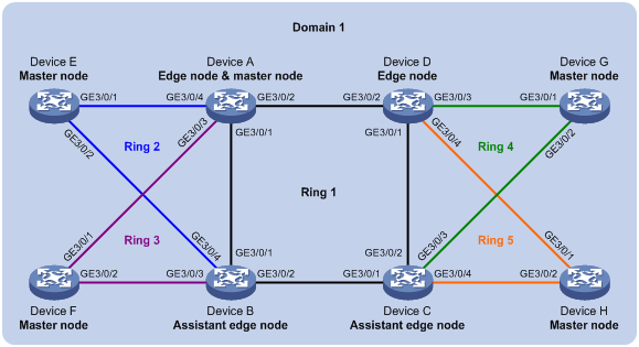
As shown in Figure 10,
· Device A through Device H form RRPP domain 1. Specify the primary control VLAN of RRPP domain 1 as VLAN 4092, and specify that RRPP domain 1 protects VLANs 1 through 30.
· Device A through Device D form primary ring 1. Device A, Device B, and Device E form subring 2. Device A, Device B, and Device F form subring 3. Device C, Device D, and Device G form subring 4. Device C, Device D, and Device H form subring 5.
Specify Device A as the master node of primary ring 1, GigabitEthernet 3/0/1 as the primary port and GigabitEthernet 3/0/2 as the secondary port. Specify Device E as the master node of subring 2, GigabitEthernet 3/0/1 as the primary port and GigabitEthernet 3/0/2 as the secondary port. Specify Device F as the master node of subring 3, GigabitEthernet 3/0/1 as the primary port and GigabitEthernet 3/0/2 as the secondary port. Specify Device G as the master node of subring 4, GigabitEthernet 3/0/1 as the primary port and GigabitEthernet 3/0/2 as the secondary port. Specify Device H as the master node of subring 5, GigabitEthernet 3/0/1 as the primary port and GigabitEthernet 3/0/2 as the secondary port.
Specify Device A as the edge node of the connected subrings, its GigabitEthernet 3/0/3 and GigabitEthernet 3/0/4 as the edge ports. Specify Device D as the transit node of the primary ring and edge node of the connected subrings, its GigabitEthernet 3/0/3 and GigabitEthernet 3/0/4 as the edge ports. Specify Device B and Device C as the transit node of the primary ring and assistant-edge nodes of the connected subrings, their GigabitEthernet 3/0/3 and GigabitEthernet 3/0/4 as the edge ports.
|
|
NOTE: Configure the primary and secondary ports on the master nodes properly to make sure that other protocols still work properly when data VLANs are denied by the secondary ports. |
Configuration procedure
1. Configure Device A.
# Create VLANs 1 through 30, map these VLANs to MSTI 1, and activate the MST region configuration.
<DeviceA> system-view
[DeviceA] vlan 1 to 30
[DeviceA] stp region-configuration
[DeviceA-mst-region] instance 1 vlan 1 to 30
[DeviceA-mst-region] active region-configuration
[DeviceA-mst-region] quit
# Set the physical state change suppression interval to 0 seconds on GigabitEthernet 3/0/1 through GigabitEthernet 3/0/4, disable the spanning tree feature, configure the four ports as trunk ports, and assign them to VLANs 1 through 30.
[DeviceA] interface gigabitEthernet3/0/1
[DeviceA-GigabitEthernet3/0/1] link-delay 0
[DeviceA-GigabitEthernet3/0/1] undo stp enable
[DeviceA-GigabitEthernet3/0/1] port link-type trunk
[DeviceA-GigabitEthernet3/0/1] port trunk permit vlan 1 to 30
[DeviceA-GigabitEthernet3/0/1] quit
[DeviceA] interface gigabitEthernet3/0/2
[DeviceA-GigabitEthernet3/0/2] link-delay 0
[DeviceA-GigabitEthernet3/0/2] undo stp enable
[DeviceA-GigabitEthernet3/0/2] port link-type trunk
[DeviceA-GigabitEthernet3/0/2] port trunk permit vlan 1 to 30
[DeviceA-GigabitEthernet3/0/2] quit
[DeviceA] interface gigabitEthernet3/0/3
[DeviceA-GigabitEthernet3/0/3] link-delay 0
[DeviceA-GigabitEthernet3/0/3] undo stp enable
[DeviceA-GigabitEthernet3/0/3] port link-type trunk
[DeviceA-GigabitEthernet3/0/3] port trunk permit vlan 1 to 30
[DeviceA-GigabitEthernet3/0/3] quit
[DeviceA] interface gigabitEthernet3/0/4
[DeviceA-GigabitEthernet3/0/4] link-delay 0
[DeviceA-GigabitEthernet3/0/4] undo stp enable
[DeviceA-GigabitEthernet3/0/4] port link-type trunk
[DeviceA-GigabitEthernet3/0/4] port trunk permit vlan 1 to 30
[DeviceA-GigabitEthernet3/0/4] quit
# Create RRPP domain 1, configure VLAN 4092 as the primary control VLAN of RRPP domain 1, and configure the VLANs mapped to MSTI 1 as the protected VLANs of RRPP domain 1.
[DeviceA] rrpp domain 1
[DeviceA-rrpp-domain1] control-vlan 4092
[DeviceA-rrpp-domain1] protected-vlan reference-instance 1
# Configure Device A as the master node of primary ring 1, with GigabitEthernet 3/0/1 as the primary port and GigabitEthernet 3/0/2 as the secondary port, and enable ring 1.
[DeviceA-rrpp-domain1] ring 1 node-mode master primary-port gigabitEthernet3/0/1 secondary-port gigabitEthernet3/0/2 level 0
[DeviceA-rrpp-domain1] ring 1 enable
# Configure Device A as the edge node of subring 2, with GigabitEthernet 3/0/4 as the edge port, and enable subring 2.
[DeviceA-rrpp-domain1] ring 2 node-mode edge edge-port gigabitEthernet3/0/4
[DeviceA-rrpp-domain1] ring 2 enable
# Configure Device A as the edge node of subring 3, with GigabitEthernet 3/0/3 as the edge port, and enable subring 3.
[DeviceA-rrpp-domain1] ring 3 node-mode edge edge-port gigabitEthernet3/0/3
[DeviceA-rrpp-domain1] ring 3 enable
[DeviceA-rrpp-domain1] quit
# Enable RRPP.
[DeviceA] rrpp enable
2. Configure Device B.
# Create VLANs 1 through 30, map these VLANs to MSTI 1, and activate the MST region configuration.
<DeviceB> system-view
[DeviceB] vlan 1 to 30
[DeviceB] stp region-configuration
[DeviceB-mst-region] instance 1 vlan 1 to 30
[DeviceB-mst-region] active region-configuration
[DeviceB-mst-region] quit
# Set the physical state change suppression interval to 0 seconds on GigabitEthernet 3/0/1 through GigabitEthernet 3/0/4, disable the spanning tree feature, configure the four ports as trunk ports, and assign them to VLANs 1 through 30.
[DeviceB] interface gigabitEthernet3/0/1
[DeviceB-GigabitEthernet3/0/1] link-delay 0
[DeviceB-GigabitEthernet3/0/1] undo stp enable
[DeviceB-GigabitEthernet3/0/1] port link-type trunk
[DeviceB-GigabitEthernet3/0/1] port trunk permit vlan 1 to 30
[DeviceB-GigabitEthernet3/0/1] quit
[DeviceB] interface gigabitEthernet3/0/2
[DeviceB-GigabitEthernet3/0/2] link-delay 0
[DeviceB-GigabitEthernet3/0/2] undo stp enable
[DeviceB-GigabitEthernet3/0/2] port link-type trunk
[DeviceB-GigabitEthernet3/0/2] port trunk permit vlan 1 to 30
[DeviceB-GigabitEthernet3/0/2] quit
[DeviceB] interface gigabitEthernet3/0/3
[DeviceB-GigabitEthernet3/0/3] link-delay 0
[DeviceB-GigabitEthernet3/0/3] undo stp enable
[DeviceB-GigabitEthernet3/0/3] port link-type trunk
[DeviceB-GigabitEthernet3/0/3] port trunk permit vlan 1 to 30
[DeviceB-GigabitEthernet3/0/3] quit
[DeviceB] interface gigabitEthernet3/0/4
[DeviceB-GigabitEthernet3/0/4] link-delay 0
[DeviceB-GigabitEthernet3/0/4] undo stp enable
[DeviceB-GigabitEthernet3/0/4] port link-type trunk
[DeviceB-GigabitEthernet3/0/4] port trunk permit vlan 1 to 30
[DeviceB-GigabitEthernet3/0/4] quit
# Create RRPP domain 1, configure VLAN 4092 as the primary control VLAN of RRPP domain 1, and configure the VLANs mapped to MSTI 1 as the protected VLANs of RRPP domain 1.
[DeviceB] rrpp domain 1
[DeviceB-rrpp-domain1] control-vlan 4092
[DeviceB-rrpp-domain1] protected-vlan reference-instance 1
# Configure Device B as the transit node of primary ring 1, with GigabitEthernet 3/0/1 as the primary port and GigabitEthernet 3/0/2 as the secondary port, and enable ring 1.
[DeviceB-rrpp-domain1] ring 1 node-mode transit primary-port gigabitEthernet3/0/1 secondary-port gigabitEthernet3/0/2 level 0
[DeviceB-rrpp-domain1] ring 1 enable
# Configure Device B as the assistant-edge node of subring 2, with GigabitEthernet 3/0/4 as the edge port, and enable subring 2.
[DeviceB-rrpp-domain1] ring 2 node-mode assistant-edge edge-port gigabitEthernet3/0/4
[DeviceB-rrpp-domain1] ring 2 enable
# Configure Device B as the assistant-edge node of subring 3, with GigabitEthernet 3/0/3 as the edge port, and enable subring 3.
[DeviceB-rrpp-domain1] ring 3 node-mode assistant-edge edge-port gigabitEthernet3/0/3
[DeviceB-rrpp-domain1] ring 3 enable
[DeviceB-rrpp-domain1] quit
# Enable RRPP.
[DeviceB] rrpp enable
3. Configure Device C.
# Create VLANs 1 through 30, map these VLANs to MSTI 1, and activate the MST region configuration.
<DeviceC> system-view
[DeviceC] vlan 1 to 30
[DeviceC] stp region-configuration
[DeviceC-mst-region] instance 1 vlan 1 to 30
[DeviceC-mst-region] active region-configuration
[DeviceC-mst-region] quit
# Set the physical state change suppression interval to 0 seconds on GigabitEthernet 3/0/1 through GigabitEthernet 3/0/4, disable the spanning tree feature, configure the four ports as trunk ports, and assign them to VLANs 1 through 30.
[DeviceC] interface gigabitEthernet3/0/1
[DeviceC-GigabitEthernet3/0/1] link-delay 0
[DeviceC-GigabitEthernet3/0/1] undo stp enable
[DeviceC-GigabitEthernet3/0/1] port link-type trunk
[DeviceC-GigabitEthernet3/0/1] port trunk permit vlan 1 to 30
[DeviceC-GigabitEthernet3/0/1] quit
[DeviceC] interface gigabitEthernet3/0/2
[DeviceC-GigabitEthernet3/0/2] link-delay 0
[DeviceC-GigabitEthernet3/0/2] undo stp enable
[DeviceC-GigabitEthernet3/0/2] port link-type trunk
[DeviceC-GigabitEthernet3/0/2] port trunk permit vlan 1 to 30
[DeviceC-GigabitEthernet3/0/2] quit
[DeviceC] interface gigabitEthernet3/0/3
[DeviceC-GigabitEthernet3/0/3] link-delay 0
[DeviceC-GigabitEthernet3/0/3] undo stp enable
[DeviceC-GigabitEthernet3/0/3] port link-type trunk
[DeviceC-GigabitEthernet3/0/3] port trunk permit vlan 1 to 30
[DeviceC-GigabitEthernet3/0/3] quit
[DeviceC] interface gigabitEthernet3/0/4
[DeviceC-GigabitEthernet3/0/4] link-delay 0
[DeviceC-GigabitEthernet3/0/4] undo stp enable
[DeviceC-GigabitEthernet3/0/4] port link-type trunk
[DeviceC-GigabitEthernet3/0/4] port trunk permit vlan 1 to 30
[DeviceC-GigabitEthernet3/0/4] quit
# Create RRPP domain 1, configure VLAN 4092 as the primary control VLAN of RRPP domain 1, and configure the VLANs mapped to MSTI 1 as the protected VLANs of RRPP domain 1.
[DeviceC] rrpp domain 1
[DeviceC-rrpp-domain1] control-vlan 4092
[DeviceC-rrpp-domain1] protected-vlan reference-instance 1
# Configure Device C as the transit node of primary ring 1, with GigabitEthernet 3/0/1 as the primary port and GigabitEthernet 3/0/2 as the secondary port, and enable ring 1.
[DeviceC-rrpp-domain1] ring 1 node-mode transit primary-port gigabitEthernet3/0/1 secondary-port gigabitEthernet3/0/2 level 0
[DeviceC-rrpp-domain1] ring 1 enable
# Configure Device C as the assistant-edge node of subring 4, with GigabitEthernet 3/0/3 as the edge port, and enable subring 4.
[DeviceC-rrpp-domain1] ring 4 node-mode assistant-edge edge-port gigabitEthernet3/0/3
[DeviceC-rrpp-domain1] ring 4 enable
# Configure Device C as the assistant-edge node of subring 5, with GigabitEthernet 3/0/4 as the edge port, and enable subring 5.
[DeviceC-rrpp-domain1] ring 5 node-mode assistant-edge edge-port gigabitEthernet3/0/4
[DeviceC-rrpp-domain1] ring 5 enable
[DeviceC-rrpp-domain1] quit
# Enable RRPP.
[DeviceC] rrpp enable
4. Configure Device D.
# Create VLANs 1 through 30, map these VLANs to MSTI 1, and activate the MST region configuration.
<DeviceD> system-view
[DeviceD] vlan 1 to 30
[DeviceD] stp region-configuration
[DeviceD-mst-region] instance 1 vlan 1 to 30
[DeviceD-mst-region] active region-configuration
[DeviceD-mst-region] quit
# Set the physical state change suppression interval to 0 seconds on GigabitEthernet 3/0/1 through GigabitEthernet 3/0/4, disable the spanning tree feature, configure the four ports as trunk ports, and assign them to VLANs 1 through 30.
[DeviceD] interface gigabitEthernet3/0/1
[DeviceD-GigabitEthernet3/0/1] link-delay 0
[DeviceD-GigabitEthernet3/0/1] undo stp enable
[DeviceD-GigabitEthernet3/0/1] port link-type trunk
[DeviceD-GigabitEthernet3/0/1] port trunk permit vlan 1 to 30
[DeviceD-GigabitEthernet3/0/1] quit
[DeviceD] interface gigabitEthernet3/0/2
[DeviceD-GigabitEthernet3/0/2] link-delay 0
[DeviceD-GigabitEthernet3/0/2] undo stp enable
[DeviceD-GigabitEthernet3/0/2] port link-type trunk
[DeviceD-GigabitEthernet3/0/2] port trunk permit vlan 1 to 30
[DeviceD-GigabitEthernet3/0/2] quit
[DeviceD] interface gigabitEthernet3/0/3
[DeviceD-GigabitEthernet3/0/3] link-delay 0
[DeviceD-GigabitEthernet3/0/3] undo stp enable
[DeviceD-GigabitEthernet3/0/3] port link-type trunk
[DeviceD-GigabitEthernet3/0/3] port trunk permit vlan 1 to 30
[DeviceD-GigabitEthernet3/0/3] quit
[DeviceD] interface gigabitEthernet3/0/4
[DeviceD-GigabitEthernet3/0/4] link-delay 0
[DeviceD-GigabitEthernet3/0/4] undo stp enable
[DeviceD-GigabitEthernet3/0/4] port link-type trunk
[DeviceD-GigabitEthernet3/0/4] port trunk permit vlan 1 to 30
[DeviceD-GigabitEthernet3/0/4] quit
# Create RRPP domain 1, configure VLAN 4092 as the primary control VLAN of RRPP domain 1, and configure the VLANs mapped to MSTI 1 as the protected VLANs of RRPP domain 1.
[DeviceD] rrpp domain 1
[DeviceD-rrpp-domain1] control-vlan 4092
[DeviceD-rrpp-domain1] protected-vlan reference-instance 1
# Configure Device D as the transit node of primary ring 1, with GigabitEthernet 3/0/1 as the primary port and GigabitEthernet 3/0/2 as the secondary port, and enable ring 1.
[DeviceD-rrpp-domain1] ring 1 node-mode transit primary-port gigabitEthernet3/0/1 secondary-port gigabitEthernet3/0/2 level 0
[DeviceD-rrpp-domain1] ring 1 enable
# Configure Device D as the edge node of subring 4, with GigabitEthernet 3/0/3 as the edge port, and enable subring 4.
[DeviceD-rrpp-domain1] ring 4 node-mode edge edge-port gigabitEthernet3/0/3
[DeviceD-rrpp-domain1] ring 4 enable
# Configure Device D as the edge node of subring 5, with GigabitEthernet 3/0/4 as the edge port, and enable subring 5.
[DeviceD-rrpp-domain1] ring 5 node-mode edge edge-port gigabitEthernet3/0/4
[DeviceD-rrpp-domain1] ring 5 enable
[DeviceD-rrpp-domain1] quit
# Enable RRPP.
[DeviceD] rrpp enable
5. Configure Device E.
# Create VLANs 1 through 30, map these VLANs to MSTI 1, and activate the MST region configuration.
<DeviceE> system-view
[DeviceE] vlan 1 to 30
[DeviceE] stp region-configuration
[DeviceE-mst-region] instance 1 vlan 1 to 30
[DeviceE-mst-region] active region-configuration
[DeviceE-mst-region] quit
# Set the physical state change suppression interval to 0 seconds on GigabitEthernet 3/0/1 and GigabitEthernet 3/0/2, disable the spanning tree feature, configure the two ports as trunk ports, and assign them to VLANs 1 through 30.
[DeviceE] interface gigabitEthernet3/0/1
[DeviceE-GigabitEthernet3/0/1] link-delay 0
[DeviceE-GigabitEthernet3/0/1] undo stp enable
[DeviceE-GigabitEthernet3/0/1] port link-type trunk
[DeviceE-GigabitEthernet3/0/1] port trunk permit vlan 1 to 30
[DeviceE-GigabitEthernet3/0/1] quit
[DeviceE] interface gigabitEthernet3/0/2
[DeviceE-GigabitEthernet3/0/2] link-delay 0
[DeviceE-GigabitEthernet3/0/2] undo stp enable
[DeviceE-GigabitEthernet3/0/2] port link-type trunk
[DeviceE-GigabitEthernet3/0/2] port trunk permit vlan 1 to 30
[DeviceE-GigabitEthernet3/0/2] quit
# Create RRPP domain 1, configure VLAN 4092 as the primary control VLAN of RRPP domain 1, and configure the VLANs mapped to MSTI 1 as the protected VLANs of RRPP domain 1.
[DeviceE] rrpp domain 1
[DeviceE-rrpp-domain1] control-vlan 4092
[DeviceE-rrpp-domain1] protected-vlan reference-instance 1
# Configure Device E as the master node of subring 2, with GigabitEthernet 3/0/1 as the primary port and GigabitEthernet 3/0/2 as the secondary port, and enable subring 2.
[DeviceE-rrpp-domain1] ring 2 node-mode master primary-port gigabitEthernet3/0/1 secondary-port gigabitEthernet3/0/2 level 1
[DeviceE-rrpp-domain1] ring 2 enable
[DeviceE-rrpp-domain1] quit
# Enable RRPP.
[DeviceE] rrpp enable
6. Configure Device F.
# Create VLANs 1 through 30, map these VLANs to MSTI 1, and activate the MST region configuration.
<DeviceF> system-view
[DeviceF] vlan 1 to 30
[DeviceF] stp region-configuration
[DeviceF-mst-region] instance 1 vlan 1 to 30
[DeviceF-mst-region] active region-configuration
[DeviceF-mst-region] quit
# Set the physical state change suppression interval to 0 seconds on GigabitEthernet 3/0/1 and GigabitEthernet 3/0/2, disable the spanning tree feature, configure the two ports as trunk ports, and assign them to VLANs 1 through 30.
[DeviceF] interface gigabitEthernet3/0/1
[DeviceF-GigabitEthernet3/0/1] link-delay 0
[DeviceF-GigabitEthernet3/0/1] undo stp enable
[DeviceF-GigabitEthernet3/0/1] port link-type trunk
[DeviceF-GigabitEthernet3/0/1] port trunk permit vlan 1 to 30
[DeviceF-GigabitEthernet3/0/1] quit
[DeviceF] interface gigabitEthernet3/0/2
[DeviceF-GigabitEthernet3/0/2] link-delay 0
[DeviceF-GigabitEthernet3/0/2] undo stp enable
[DeviceF-GigabitEthernet3/0/2] port link-type trunk
[DeviceF-GigabitEthernet3/0/2] port trunk permit vlan 1 to 30
[DeviceF-GigabitEthernet3/0/2] quit
# Create RRPP domain 1, configure VLAN 4092 as the primary control VLAN of RRPP domain 1, and configure the VLANs mapped to MSTI 1 as the protected VLANs of RRPP domain 1.
[DeviceF] rrpp domain 1
[DeviceF-rrpp-domain1] control-vlan 4092
[DeviceF-rrpp-domain1] protected-vlan reference-instance 1
# Configure Device F as the master node of subring 3, with GigabitEthernet 3/0/1 as the primary port and GigabitEthernet 3/0/2 as the secondary port, and enable subring 3.
[DeviceF-rrpp-domain1] ring 3 node-mode master primary-port gigabitEthernet3/0/1 secondary-port gigabitEthernet3/0/2 level 1
[DeviceF-rrpp-domain1] ring 3 enable
[DeviceF-rrpp-domain1] quit
# Enable RRPP.
[DeviceF] rrpp enable
7. Configure Device G.
# Create VLANs 1 through 30, map these VLANs to MSTI 1, and activate the MST region configuration.
<DeviceG> system-view
[DeviceG] vlan 1 to 30
[DeviceG] stp region-configuration
[DeviceG-mst-region] instance 1 vlan 1 to 30
[DeviceG-mst-region] active region-configuration
[DeviceG-mst-region] quit
# Set the physical state change suppression interval to 0 seconds on GigabitEthernet 3/0/1 and GigabitEthernet 3/0/2, disable the spanning tree feature, configure the two ports as trunk ports, and assign them to VLANs 1 through 30.
[DeviceG] interface gigabitEthernet3/0/1
[DeviceG-GigabitEthernet3/0/1] link-delay 0
[DeviceG-GigabitEthernet3/0/1] undo stp enable
[DeviceG-GigabitEthernet3/0/1] port link-type trunk
[DeviceG-GigabitEthernet3/0/1] port trunk permit vlan 1 to 30
[DeviceG-GigabitEthernet3/0/1] quit
[DeviceG] interface gigabitEthernet3/0/2
[DeviceG-GigabitEthernet3/0/2] link-delay 0
[DeviceG-GigabitEthernet3/0/2] undo stp enable
[DeviceG-GigabitEthernet3/0/2] port link-type trunk
[DeviceG-GigabitEthernet3/0/2] port trunk permit vlan 1 to 30
[DeviceG-GigabitEthernet3/0/2] quit
# Create RRPP domain 1, configure VLAN 4092 as the primary control VLAN of RRPP domain 1, and configure the VLANs mapped to MSTI 1 as the protected VLANs of RRPP domain 1.
[DeviceG] rrpp domain 1
[DeviceG-rrpp-domain1] control-vlan 4092
[DeviceG-rrpp-domain1] protected-vlan reference-instance 1
# Configure Device G as the master node of subring 4, with GigabitEthernet 3/0/1 as the primary port and GigabitEthernet 3/0/2 as the secondary port, and enable subring 4.
[DeviceG-rrpp-domain1] ring 4 node-mode master primary-port gigabitEthernet3/0/1 secondary-port gigabitEthernet3/0/2 level 1
[DeviceG-rrpp-domain1] ring 4 enable
[DeviceG-rrpp-domain1] quit
# Enable RRPP.
[DeviceG] rrpp enable
8. Configure Device H.
# Create VLANs 1 through 30, map these VLANs to MSTI 1, and activate the MST region configuration.
<DeviceH> system-view
[DeviceH] vlan 1 to 30
[DeviceH] stp region-configuration
[DeviceH-mst-region] instance 1 vlan 1 to 30
[DeviceH-mst-region] active region-configuration
[DeviceH-mst-region] quit
# Set the physical state change suppression interval to 0 seconds on GigabitEthernet 3/0/1 and GigabitEthernet 3/0/2, disable the spanning tree feature, configure the two ports as trunk ports, and assign them to VLANs 1 through 30.
[DeviceH] interface gigabitEthernet3/0/1
[DeviceH-GigabitEthernet3/0/1] link-delay 0
[DeviceH-GigabitEthernet3/0/1] undo stp enable
[DeviceH-GigabitEthernet3/0/1] port link-type trunk
[DeviceH-GigabitEthernet3/0/1] port trunk permit vlan 1 to 30
[DeviceH-GigabitEthernet3/0/1] quit
[DeviceH] interface gigabitEthernet3/0/2
[DeviceH-GigabitEthernet3/0/2] link-delay 0
[DeviceH-GigabitEthernet3/0/2] undo stp enable
[DeviceH-GigabitEthernet3/0/2] port link-type trunk
[DeviceH-GigabitEthernet3/0/2] port trunk permit vlan 1 to 30
[DeviceH-GigabitEthernet3/0/2] quit
# Create RRPP domain 1, configure VLAN 4092 as the primary control VLAN of RRPP domain 1, and configure the VLANs mapped to MSTI 1 as the protected VLANs of RRPP domain 1.
[DeviceH] rrpp domain 1
[DeviceH-rrpp-domain1] control-vlan 4092
[DeviceH-rrpp-domain1] protected-vlan reference-instance 1
# Configure Device H as the master node of subring 5, with GigabitEthernet 3/0/1 as the primary port and GigabitEthernet 3/0/2 as the secondary port, and enable subring 5.
[DeviceH-rrpp-domain1] ring 5 node-mode master primary-port gigabitEthernet3/0/1 secondary-port gigabitEthernet3/0/2 level 1
[DeviceH-rrpp-domain1] ring 5 enable
[DeviceH-rrpp-domain1] quit
# Enable RRPP.
[DeviceH] rrpp enable
9. Verify the configuration.
Use the display command to view RRPP configuration and operational information on each device.
Intersecting-ring load balancing configuration example
Networking requirements
As shown in Figure 11,
· Device A, Device B, Device C, Device D, and Device F form RRPP domain 1, and VLAN 100 is the primary control VLAN of the RRPP domain. Device A is the master node of the primary ring, Ring 1; Device D is the transit node of Ring 1; Device F is the master node of the subring Ring 3; Device C is the edge node of the subring Ring 3; Device B is the assistant-edge node of the subring Ring 3.
· Device A, Device B, Device C, Device D, and Device E form RRPP domain 2, and VLAN 105 is the primary control VLAN of the RRPP domain. Device A is the master node of the primary ring, Ring 1; Device D is the transit node of Ring 1; Device E is the master node of the subring Ring 2; Device C is the edge node of the subring Ring 2; Device B is the assistant-edge node of the subring Ring 2.
Specify VLAN 10 as the protected VLAN of domain 1, and VLAN 20 the protected VLAN of domain 2. You can implement VLAN-based load balancing on Ring 1.
As the edge node and assistant-edge node of Ring 2 is the same as those of Ring 3, and the two subrings have the same SRPTs, you can add Ring 2 and Ring 3 to the RRPP ring group to reduce Edge-Hello traffic.
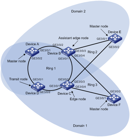
Configuration procedure
1. Configure Device A.
# Create VLANs 10 and 20, map VLAN 10 to MSTI 1 and VLAN 20 to MSTI 2, and activate MST region configuration.
<DeviceA> system-view
[DeviceA] vlan 10
[DeviceA-vlan10] quit
[DeviceA] vlan 20
[DeviceA-vlan20] quit
[DeviceA] stp region-configuration
[DeviceA-mst-region] instance 1 vlan 10
[DeviceA-mst-region] instance 2 vlan 20
[DeviceA-mst-region] active region-configuration
[DeviceA-mst-region] quit
# Set the physical state change suppression interval to 0 seconds on GigabitEthernet 3/0/1 and GigabitEthernet 3/0/2, disable the spanning tree feature, configure the two ports as trunk ports, remove them from VLAN 1, and assign them to VLANs 10 and 20.
[DeviceA] interface gigabitethernet 3/0/1
[DeviceA-GigabitEthernet3/0/1] link-delay 0
[DeviceA-GigabitEthernet3/0/1] undo stp enable
[DeviceA-GigabitEthernet3/0/1] port link-type trunk
[DeviceA-GigabitEthernet3/0/1] undo port trunk permit vlan 1
[DeviceA-GigabitEthernet3/0/1] port trunk permit vlan 10 20
[DeviceA-GigabitEthernet3/0/1] quit
[DeviceA] interface gigabitethernet 3/0/2
[DeviceA-GigabitEthernet3/0/2] link-delay 0
[DeviceA-GigabitEthernet3/0/2] undo stp enable
[DeviceA-GigabitEthernet3/0/2] port link-type trunk
[DeviceA-GigabitEthernet3/0/2] undo port trunk permit vlan 1
[DeviceA-GigabitEthernet3/0/2] port trunk permit vlan 10 20
[DeviceA-GigabitEthernet3/0/2] quit
# Create RRPP domain 1, configure VLAN 100 as the primary control VLAN of RRPP domain 1, and configure the VLAN mapped to MSTI 1 as the protected VLAN of RRPP domain 1.
[DeviceA] rrpp domain 1
[DeviceA-rrpp-domain1] control-vlan 100
[DeviceA-rrpp-domain1] protected-vlan reference-instance 1
# Configure Device A as the master node of primary ring 1, with GigabitEthernet 3/0/1 as the primary port and GigabitEthernet 3/0/2 as the secondary port, and enable ring 1.
[DeviceA-rrpp-domain1] ring 1 node-mode master primary-port gigabitethernet 3/0/1 secondary-port gigabitethernet 3/0/2 level 0
[DeviceA-rrpp-domain1] ring 1 enable
[DeviceA-rrpp-domain1] quit
# Create RRPP domain 2, configure VLAN 105 as the primary control VLAN of RRPP domain 2, and configure the VLAN mapped to MSTI 2 as the protected VLAN of RRPP domain 2.
[DeviceA] rrpp domain 2
[DeviceA-rrpp-domain2] control-vlan 105
[DeviceA-rrpp-domain2] protected-vlan reference-instance 2
# Configure Device A as the master node of primary ring 1, with GigabitEthernet 3/0/2 as the master port and GigabitEthernet 3/0/1 as the secondary port, and enable ring 1.
[DeviceA-rrpp-domain2] ring 1 node-mode master primary-port gigabitethernet 3/0/2 secondary-port gigabitethernet 3/0/1 level 0
[DeviceA-rrpp-domain2] ring 1 enable
[DeviceA-rrpp-domain2] quit
# Enable RRPP.
[DeviceA] rrpp enable
2. Configure Device B.
# Create VLANs 10 and 20, map VLAN 10 to MSTI 1 and VLAN 20 to MSTI 2, and activate MST region configuration.
<DeviceB> system-view
[DeviceB] vlan 10
[DeviceB-vlan10] quit
[DeviceB] vlan 20
[DeviceB-vlan20] quit
[DeviceB] stp region-configuration
[DeviceB-mst-region] instance 1 vlan 10
[DeviceB-mst-region] instance 2 vlan 20
[DeviceB-mst-region] active region-configuration
[DeviceB-mst-region] quit
# Set the physical state change suppression interval to 0 seconds on GigabitEthernet 3/0/1 and GigabitEthernet 3/0/2, disable the spanning tree feature, configure the two ports as trunk ports, remove them from VLAN 1, and assign them to VLANs 10 and 20.
[DeviceB] interface gigabitethernet 3/0/1
[DeviceB-GigabitEthernet3/0/1] link-delay 0
[DeviceB-GigabitEthernet3/0/1] undo stp enable
[DeviceB-GigabitEthernet3/0/1] port link-type trunk
[DeviceB-GigabitEthernet3/0/1] undo port trunk permit vlan 1
[DeviceB-GigabitEthernet3/0/1] port trunk permit vlan 10 20
[DeviceB-GigabitEthernet3/0/1] quit
[DeviceB] interface gigabitethernet 3/0/2
[DeviceB-GigabitEthernet3/0/2] link-delay 0
[DeviceB-GigabitEthernet3/0/2] undo stp enable
[DeviceB-GigabitEthernet3/0/2] port link-type trunk
[DeviceB-GigabitEthernet3/0/2] undo port trunk permit vlan 1
[DeviceB-GigabitEthernet3/0/2] port trunk permit vlan 10 20
[DeviceB-GigabitEthernet3/0/2] quit
# Set the physical state change suppression interval to 0 seconds on GigabitEthernet 3/0/3, disable the spanning tree feature, configure the port as a trunk port, remove it from VLAN 1, and assign it to VLAN 20.
[DeviceB] interface gigabitethernet 3/0/3
[DeviceB-GigabitEthernet3/0/3] link-delay 0
[DeviceB-GigabitEthernet3/0/3] undo stp enable
[DeviceB-GigabitEthernet3/0/3] port link-type trunk
[DeviceB-GigabitEthernet3/0/3] undo port trunk permit vlan 1
[DeviceB-GigabitEthernet3/0/3] port trunk permit vlan 20
[DeviceB-GigabitEthernet3/0/3] quit
# Set the physical state change suppression interval to 0 seconds on GigabitEthernet 3/0/4, disable the spanning tree feature, configure the port as a trunk port, remove it from VLAN 1, and assign it to VLAN 10.
[DeviceB] interface gigabitethernet 3/0/4
[DeviceB-GigabitEthernet3/0/4] link-delay 0
[DeviceB-GigabitEthernet3/0/4] undo stp enable
[DeviceB-GigabitEthernet3/0/4] port link-type trunk
[DeviceB-GigabitEthernet3/0/4] undo port trunk permit vlan 1
[DeviceB-GigabitEthernet3/0/4] port trunk permit vlan 10
[DeviceB-GigabitEthernet3/0/4] quit
# Create RRPP domain 1, configure VLAN 100 as the primary control VLAN of RRPP domain 1, and configure the VLAN mapped to MSTI 1 as the protected VLAN of RRPP domain 1.
[DeviceB] rrpp domain 1
[DeviceB-rrpp-domain1] control-vlan 100
[DeviceB-rrpp-domain1] protected-vlan reference-instance 1
# Configure Device B as a transit node of primary ring 1 in RRPP domain 1, with GigabitEthernet 3/0/1 as the primary port and GigabitEthernet 3/0/2 as the secondary port, and enable ring 1.
[DeviceB-rrpp-domain1] ring 1 node-mode transit primary-port gigabitethernet 3/0/1 secondary-port gigabitethernet 3/0/2 level 0
[DeviceB-rrpp-domain1] ring 1 enable
# Configure Device B as the assistant-edge node of subring 3 in RRPP domain 1, with GigabitEthernet 3/0/4 as the edge port, and enable subring 3.
[DeviceB-rrpp-domain1] ring 3 node-mode assistant-edge edge-port gigabitethernet 3/0/4
[DeviceB-rrpp-domain1] ring 3 enable
[DeviceB-rrpp-domain1] quit
# Create RRPP domain 2, configure VLAN 105 as the primary control VLAN of RRPP domain 2, and configure the VLAN mapped to MSTI 2 as the protected VLAN of RRPP domain 2.
[DeviceB] rrpp domain 2
[DeviceB-rrpp-domain2] control-vlan 105
[DeviceB-rrpp-domain2] protected-vlan reference-instance 2
# Configure Device B as the transit node of primary ring 1, with GigabitEthernet 3/0/1 as the primary port and GigabitEthernet 3/0/2 as the secondary port, and enable ring 1.
[DeviceB-rrpp-domain2] ring 1 node-mode transit primary-port gigabitethernet 3/0/1 secondary-port gigabitethernet 3/0/2 level 0
[DeviceB-rrpp-domain2] ring 1 enable
# Configure Device B as the assistant-edge node of subring 2 in RRPP domain 2, with GigabitEthernet 3/0/3 as the edge port, and enable subring 2.
[DeviceB-rrpp-domain2] ring 2 node-mode assistant-edge edge-port gigabitethernet 3/0/3
[DeviceB-rrpp-domain2] ring 2 enable
[DeviceB-rrpp-domain2] quit
# Enable RRPP.
[DeviceB] rrpp enable
3. Configure Device C.
# Create VLANs 10 and 20, map VLAN 10 to MSTI 1 and VLAN 20 to MSTI 2, and activate MST region configuration.
<DeviceC> system-view
[DeviceC] vlan 10
[DeviceC-vlan10] quit
[DeviceC] vlan 20
[DeviceC-vlan20] quit
[DeviceC] stp region-configuration
[DeviceC-mst-region] instance 1 vlan 10
[DeviceC-mst-region] instance 2 vlan 20
[DeviceC-mst-region] active region-configuration
[DeviceC-mst-region] quit
# Set the physical state change suppression interval to 0 seconds on GigabitEthernet 3/0/1 and GigabitEthernet 3/0/2, disable the spanning tree feature, configure the two ports as trunk ports, remove them from VLAN 1, and assign them to VLANs 10 and 20.
[DeviceC] interface gigabitethernet 3/0/1
[DeviceC-GigabitEthernet3/0/1] link-delay 0
[DeviceC-GigabitEthernet3/0/1] undo stp enable
[DeviceC-GigabitEthernet3/0/1] port link-type trunk
[DeviceC-GigabitEthernet3/0/1] undo port trunk permit vlan 1
[DeviceC-GigabitEthernet3/0/1] port trunk permit vlan 10 20
[DeviceC-GigabitEthernet3/0/1] quit
[DeviceC] interface gigabitethernet 3/0/2
[DeviceC-GigabitEthernet3/0/2] link-delay 0
[DeviceC-GigabitEthernet3/0/2] undo stp enable
[DeviceC-GigabitEthernet3/0/2] port link-type trunk
[DeviceC-GigabitEthernet3/0/2] undo port trunk permit vlan 1
[DeviceC-GigabitEthernet3/0/2] port trunk permit vlan 10 20
[DeviceC-GigabitEthernet3/0/2] quit
# Set the physical state change suppression interval to 0 seconds on GigabitEthernet 3/0/3, disable the spanning tree feature, configure the port as a trunk port, remove it from VLAN 1, and assign it to VLAN 20.
[DeviceC] interface gigabitethernet 3/0/3
[DeviceC-GigabitEthernet3/0/3] link-delay 0
[DeviceC-GigabitEthernet3/0/3] undo stp enable
[DeviceC-GigabitEthernet3/0/3] port link-type trunk
[DeviceC-GigabitEthernet3/0/3] undo port trunk permit vlan 1
[DeviceC-GigabitEthernet3/0/3] port trunk permit vlan 20
[DeviceC-GigabitEthernet3/0/3] quit
# Set the physical state change suppression interval to 0 seconds on GigabitEthernet 3/0/4, disable the spanning tree feature, configure the port as a trunk port, remove it from VLAN 1, and assign it to VLAN 10.
[DeviceC] interface gigabitethernet 3/0/4
[DeviceC-GigabitEthernet3/0/4] link-delay 0
[DeviceC-GigabitEthernet3/0/4] undo stp enable
[DeviceC-GigabitEthernet3/0/4] port link-type trunk
[DeviceC-GigabitEthernet3/0/4] undo port trunk permit vlan 1
[DeviceC-GigabitEthernet3/0/4] port trunk permit vlan 10
[DeviceC-GigabitEthernet3/0/4] quit
# Create RRPP domain 1, configure VLAN 100 as the primary control VLAN of RRPP domain 1, and configure the VLAN mapped to MSTI 1 as the protected VLAN of RRPP domain 1.
[DeviceC] rrpp domain 1
[DeviceC-rrpp-domain1] control-vlan 100
[DeviceC-rrpp-domain1] protected-vlan reference-instance 1
# Configure Device C as the transit node of primary ring 1 in RRPP domain 1, with GigabitEthernet 3/0/1 as the primary port and GigabitEthernet 3/0/2 as the secondary port, and enable ring 1.
[DeviceC-rrpp-domain1] ring 1 node-mode transit primary-port gigabitethernet 3/0/1 secondary-port gigabitethernet 3/0/2 level 0
[DeviceC-rrpp-domain1] ring 1 enable
# Configure Device C as the edge node of subring 3 in RRPP domain 1, with GigabitEthernet 3/0/4 as the edge port, and enable subring 3.
[DeviceC-rrpp-domain1] ring 3 node-mode edge edge-port gigabitethernet 3/0/4
[DeviceC-rrpp-domain1] ring 3 enable
[DeviceC-rrpp-domain1] quit
# Create RRPP domain 2, configure VLAN 105 as the primary control VLAN of RRPP domain 2, and configure the VLAN mapped to MSTI 2 as the protected VLAN of RRPP domain 2.
[DeviceC] rrpp domain 2
[DeviceC-rrpp-domain2] control-vlan 105
[DeviceC-rrpp-domain2] protected-vlan reference-instance 2
# Configure Device C as the transit node of primary ring 1 in RRPP domain 2, with GigabitEthernet 3/0/1 as the primary port and GigabitEthernet 3/0/2 as the secondary port, and enable ring 1.
[DeviceC-rrpp-domain2] ring 1 node-mode transit primary-port gigabitethernet 3/0/1 secondary-port gigabitethernet 3/0/2 level 0
[DeviceC-rrpp-domain2] ring 1 enable
# Configure Device C as the edge node of subring 2 in RRPP domain 2, with GigabitEthernet 3/0/3 as the edge port, and enable subring 2.
[DeviceC-rrpp-domain2] ring 2 node-mode edge edge-port GigabitEthernet3/0/3
[DeviceC-rrpp-domain2] ring 2 enable
[DeviceC-rrpp-domain2] quit
# Enable RRPP.
[DeviceC] rrpp enable
4. Configure Device D.
# Create VLANs 10 and 20, map VLAN 10 to MSTI 1 and VLAN 20 to MSTI 2, and activate MST region configuration.
<DeviceD> system-view
[DeviceD] vlan 10
[DeviceD-vlan10] quit
[DeviceD] vlan 20
[DeviceD-vlan20] quit
[DeviceD] stp region-configuration
[DeviceD-mst-region] instance 1 vlan 10
[DeviceD-mst-region] instance 2 vlan 20
[DeviceD-mst-region] active region-configuration
[DeviceD-mst-region] quit
# Set the physical state change suppression interval to 0 seconds on GigabitEthernet 3/0/1 and GigabitEthernet 3/0/2, disable the spanning tree feature, configure the two ports as trunk ports, remove them from VLAN 1, and assign them to VLANs 10 and 20.
[DeviceD] interface gigabitethernet 3/0/1
[DeviceD-GigabitEthernet3/0/1] link-delay 0
[DeviceD-GigabitEthernet3/0/1] undo stp enable
[DeviceD-GigabitEthernet3/0/1] port link-type trunk
[DeviceD-GigabitEthernet3/0/1] undo port trunk permit vlan 1
[DeviceD-GigabitEthernet3/0/1] port trunk permit vlan 10 20
[DeviceD-GigabitEthernet3/0/1] quit
[DeviceD] interface gigabitethernet 3/0/2
[DeviceD-GigabitEthernet3/0/2] link-delay 0
[DeviceD-GigabitEthernet3/0/2] undo stp enable
[DeviceD-GigabitEthernet3/0/2] port link-type trunk
[DeviceD-GigabitEthernet3/0/2] undo port trunk permit vlan 1
[DeviceD-GigabitEthernet3/0/2] port trunk permit vlan 10 20
[DeviceD-GigabitEthernet3/0/2] quit
# Create RRPP domain 1, configure VLAN 100 as the primary control VLAN of RRPP domain 1, and configure the VLAN mapped to MSTI 1 as the protected VLAN of RRPP domain 1.
[DeviceD] rrpp domain 1
[DeviceD-rrpp-domain1] control-vlan 100
[DeviceD-rrpp-domain1] protected-vlan reference-instance 1
# Configure Device D as the transit node of primary ring 1 in RRPP domain 1, with GigabitEthernet 3/0/1 as the primary port and GigabitEthernet 3/0/2 as the secondary port, and enable ring 1.
[DeviceD-rrpp-domain1] ring 1 node-mode transit primary-port gigabitethernet 3/0/1 secondary-port gigabitethernet 3/0/2 level 0
[DeviceD-rrpp-domain1] ring 1 enable
[DeviceD-rrpp-domain1] quit
# Create RRPP domain 2, configure VLAN 105 as the primary control VLAN of RPPP domain 2, and configure the VLAN mapped to MSTI 2 as the protected VLAN of RRPP domain 2.
[DeviceD] rrpp domain 2
[DeviceD-rrpp-domain2] control-vlan 105
[DeviceD-rrpp-domain2] protected-vlan reference-instance 2
# Configure Device D as the transit node of primary ring 1 in RRPP domain 2, with GigabitEthernet 3/0/1 as the primary port and GigabitEthernet 3/0/2 as the secondary port, and enable ring 1.
[DeviceD-rrpp-domain2] ring 1 node-mode transit primary-port gigabitethernet 3/0/1 secondary-port gigabitethernet 3/0/2 level 0
[DeviceD-rrpp-domain2] ring 1 enable
[DeviceD-rrpp-domain2] quit
# Enable RRPP.
[DeviceD] rrpp enable
5. Configure Device E.
# Create VLAN 20, map VLAN 20 to MSTI 2, and activate MST region configuration.
<DeviceE> system-view
[DeviceE] vlan 20
[DeviceE-vlan20] quit
[DeviceE] stp region-configuration
[DeviceE-mst-region] instance 2 vlan 20
[DeviceE-mst-region] active region-configuration
[DeviceE-mst-region] quit
# Set the physical state change suppression interval to 0 seconds on GigabitEthernet 3/0/1 and GigabitEthernet 3/0/2, disable the spanning tree feature, configure the two ports as trunk ports, remove them from VLAN 1, and assign them to VLAN 20.
[DeviceE] interface gigabitethernet 3/0/1
[DeviceE-GigabitEthernet3/0/1] link-delay 0
[DeviceE-GigabitEthernet3/0/1] undo stp enable
[DeviceE-GigabitEthernet3/0/1] port link-type trunk
[DeviceE-GigabitEthernet3/0/1] undo port trunk permit vlan 1
[DeviceE-GigabitEthernet3/0/1] port trunk permit vlan 20
[DeviceE-GigabitEthernet3/0/1] quit
[DeviceE] interface gigabitethernet 3/0/2
[DeviceE-GigabitEthernet3/0/2] link-delay 0
[DeviceE-GigabitEthernet3/0/2] undo stp enable
[DeviceE-GigabitEthernet3/0/2] port link-type trunk
[DeviceE-GigabitEthernet3/0/2] undo port trunk permit vlan 1
[DeviceE-GigabitEthernet3/0/2] port trunk permit vlan 20
[DeviceE-GigabitEthernet3/0/2] quit
# Create RRPP domain 2, configure VLAN 105 as the primary control VLAN, and configure the VLAN mapped to MSTI 2 as the protected VLAN.
[DeviceE] rrpp domain 2
[DeviceE-rrpp-domain2] control-vlan 105
[DeviceE-rrpp-domain2] protected-vlan reference-instance 2
# Configure Device E as the master mode of subring 2 in RRPP domain 2, with GigabitEthernet 3/0/2 as the primary port and GigabitEthernet 3/0/1 as the secondary port, and enable ring 2.
[DeviceE-rrpp-domain2] ring 2 node-mode master primary-port gigabitethernet 3/0/2 secondary-port gigabitethernet 3/0/1 level 1
[DeviceE-rrpp-domain2] ring 2 enable
[DeviceE-rrpp-domain2] quit
# Enable RRPP.
[DeviceE] rrpp enable
6. Configure Device F.
# Create VLAN 10, map VLAN 10 to MSTI 1, and activate MST region configuration.
<DeviceF> system-view
[DeviceF] vlan 10
[DeviceF-vlan10] quit
[DeviceF] stp region-configuration
[DeviceF-mst-region] instance 1 vlan 10
[DeviceF-mst-region] active region-configuration
[DeviceF-mst-region] quit
# Set the physical state change suppression interval to 0 seconds on GigabitEthernet 3/0/1 and GigabitEthernet 3/0/2, disable the spanning tree feature, configure the two ports as trunk ports, remove them from VLAN 1, and assign them to VLAN 10.
[DeviceF] interface gigabitethernet 3/0/1
[DeviceF-GigabitEthernet3/0/1] link-delay 0
[DeviceF-GigabitEthernet3/0/1] undo stp enable
[DeviceF-GigabitEthernet3/0/1] port link-type trunk
[DeviceF-GigabitEthernet3/0/1] undo port trunk permit vlan 1
[DeviceF-GigabitEthernet3/0/1] port trunk permit vlan 10
[DeviceF-GigabitEthernet3/0/1] quit
[DeviceF] interface gigabitethernet 3/0/2
[DeviceF-GigabitEthernet3/0/2] link-delay 0
[DeviceF-GigabitEthernet3/0/2] undo stp enable
[DeviceF-GigabitEthernet3/0/2] port link-type trunk
[DeviceF-GigabitEthernet3/0/2] undo port trunk permit vlan 1
[DeviceF-GigabitEthernet3/0/2] port trunk permit vlan 10
[DeviceF-GigabitEthernet3/0/2] quit
# Create RRPP domain 1, configure VLAN 100 as the primary control VLAN, and configure the VLAN mapped to MSTI 1 as the protected VLAN.
[DeviceF] rrpp domain 1
[DeviceF-rrpp-domain1] control-vlan 100
[DeviceF-rrpp-domain1] protected-vlan reference-instance 1
# Configure Device F as the master node of subring 3 in RRPP domain 1, with GigabitEthernet 3/0/1 as the primary port and GigabitEthernet 3/0/2 as the secondary port, and enable subring 3.
[DeviceF-rrpp-domain1] ring 3 node-mode master primary-port gigabitethernet 3/0/1 secondary-port gigabitethernet 3/0/2 level 1
[DeviceF-rrpp-domain1] ring 3 enable
[DeviceF-rrpp-domain1] quit
# Enable RRPP.
[DeviceF] rrpp enable
7. Configure RRPP ring groups on Device B and Device C after the configurations.
# Create RRPP ring group 1 on Device B, and add subrings 2 and 3 to the RRPP ring group.
[DeviceB] rrpp ring-group 1
[DeviceB-rrpp-ring-group1] domain 2 ring 2
[DeviceB-rrpp-ring-group1] domain 1 ring 3
# Create RRPP ring group 1 on Device C, and add subrings 2 and 3 to the RRPP ring group.
[DeviceC] rrpp ring-group 1
[DeviceC-rrpp-ring-group1] domain 2 ring 2
[DeviceC-rrpp-ring-group1] domain 1 ring 3
8. Verify the configuration.
Use the display command to view RRPP configuration and operational information on each device.
Fast detection configuration example
Network requirements
As shown in Figure 12,
· Device A, Device B, Device C, and Device D constitute RRPP domain 1, VLAN 4092 is the primary control VLAN of RRPP domain 1, and RRPP domain 1 protects VLANs 10 through 30.
· Device A is the master node and supports RRPP fast detection, providing a timer resolution of 10 milliseconds (which means the default Fast-Fail and Fast-Hello timers are 60 milliseconds and 20 milliseconds, respectively); Device D is a transit node; Device B and Device C do not support RRPP.
As neither Device B nor Device C supports RRPP, when the link between them fails, the link failure cannot be detected by the master node timely. Configure RRPP fast detection to implement fast link switchover even when the link between Device B and Device C fails.
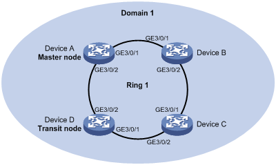
Configuration procedure
1. Configure Device A.
# Create VLANs 10 through 30, map these VLANs to MSTI 1, and activate MST region configuration.
<DeviceA> system-view
[DeviceA] vlan 1 to 30
[DeviceA] stp region-configuration
[DeviceA-mst-region] instance 1 vlan 1 to 30
[DeviceA-mst-region] active region-configuration
[DeviceA-mst-region] quit
# Set the physical state change suppression interval to 0 seconds on GigabitEthernet 3/0/1 and GigabitEthernet 3/0/2, disable the spanning tree feature, configure the two ports as trunk ports, and assign them to VLANs 10 through 30.
<DeviceA> system-view
[DeviceA] interface gigabitethernet 3/0/1
[DeviceA-GigabitEthernet3/0/1] link-delay 0
[DeviceA-GigabitEthernet3/0/1] undo stp enable
[DeviceA-GigabitEthernet3/0/1] port link-type trunk
[DeviceA-GigabitEthernet3/0/1] port trunk permit vlan 1 to 30
[DeviceA-GigabitEthernet3/0/1] quit
[DeviceA] interface gigabitethernet 3/0/2
[DeviceA-GigabitEthernet3/0/2] link-delay 0
[DeviceA-GigabitEthernet3/0/2] undo stp enable
[DeviceA-GigabitEthernet3/0/2] port link-type trunk
[DeviceA-GigabitEthernet3/0/2] port trunk permit vlan 1 to 30
[DeviceA-GigabitEthernet3/0/2] quit
# Create RRPP domain 1, configure VLAN 4092 as the primary VLAN of RPPP domain 1, and configure the VLANs mapped to MSTI 1 as the protected VLANs of RRPP domain 1.
[DeviceA] rrpp domain 1
[DeviceA-rrpp-domain1] control-vlan 4092
[DeviceA-rrpp-domain1] protected-vlan reference-instance 1
# Configure Device A as the master node of the primary ring Ring 1, with GigabitEthernet 3/0/1 as the primary port and GigabitEthernet 3/0/2 as the secondary port, and enable Ring 1.
[DeviceA-rrpp-domain1] ring 1 node-mode master primary-port gigabitethernet 3/0/1 secondary-port gigabitethernet 3/0/2 level 0
[DeviceA-rrpp-domain1] ring 1 enable
# Enable fast detection, and set the Fast-Fail timer and Fast-Hello timer to 300 milliseconds and 100 milliseconds, respectively.
[DeviceA-rrpp-domain1] fast-detection enable
[DeviceA-rrpp-domain1] timer fast-fail-timer 300
[DeviceA-rrpp-domain1] timer fast-hello-timer 100
[DeviceA-rrpp-domain1] quit
# Enable the RRPP protocol.
[DeviceA] rrpp enable
2. Configure Device B.
# Create VLAN 4092 and VLAN 4093.
<DeviceB> system-view
[DeviceB] vlan 4092 to 4093
# Set the physical state change suppression interval to 0 seconds on GigabitEthernet 3/0/1 and GigabitEthernet 3/0/2, disable the spanning tree feature, configure the two ports as trunk ports, and assign them to VLANs 1 through 30, VLAN 4092, and VLAN 4093.
<DeviceB> system-view
[DeviceB] interface gigabitethernet 3/0/1
[DeviceB-GigabitEthernet3/0/1] link-delay 0
[DeviceB-GigabitEthernet3/0/1] undo stp enable
[DeviceB-GigabitEthernet3/0/1] port link-type trunk
[DeviceB-GigabitEthernet3/0/1] port trunk permit vlan 1 to 30 4092 4093
[DeviceB-GigabitEthernet3/0/1] quit
[DeviceB] interface gigabitethernet 3/0/2
[DeviceB-GigabitEthernet3/0/2] link-delay 0
[DeviceB-GigabitEthernet3/0/2] undo stp enable
[DeviceB-GigabitEthernet3/0/2] port link-type trunk
[DeviceB-GigabitEthernet3/0/2] port trunk permit vlan 1 to 30 4092 4093
3. Configure Device C.
# Create VLAN 4092 and VLAN 4093.
<DeviceC> system-view
[DeviceC] vlan 4092 to 4093
# Set the physical state change suppression interval to 0 seconds on GigabitEthernet 3/0/1 and GigabitEthernet 3/0/2, disable the spanning tree feature, configure the two ports as trunk ports, and assign them to VLANs 1 through 30, VLAN 4092, and VLAN 4093.
<DeviceC> system-view
[DeviceC] interface gigabitethernet 3/0/1
[DeviceC-GigabitEthernet3/0/1] link-delay 0
[DeviceC-GigabitEthernet3/0/1] undo stp enable
[DeviceC-GigabitEthernet3/0/1] port link-type trunk
[DeviceC-GigabitEthernet3/0/1] port trunk permit vlan 1 to 30 4092 4093
[DeviceC-GigabitEthernet3/0/1] quit
[DeviceC] interface gigabitethernet 3/0/2
[DeviceC-GigabitEthernet3/0/2] link-delay 0
[DeviceC-GigabitEthernet3/0/2] undo stp enable
[DeviceC-GigabitEthernet3/0/2] port link-type trunk
[DeviceC-GigabitEthernet3/0/2] port trunk permit vlan 1 to 30 4092 4093
4. Configure Device D.
# Create VLANs 10 through 30, map these VLANs to MSTI 1, and activate MST region configuration.
<DeviceD> system-view
[DeviceD] vlan 1 to 30
[DeviceD] stp region-configuration
[DeviceD-mst-region] instance 1 vlan 1 to 30
[DeviceD-mst-region] active region-configuration
[DeviceD-mst-region] quit
# Set the physical state change suppression interval to 0 seconds on GigabitEthernet 3/0/1 and GigabitEthernet 3/0/2, disable the spanning tree feature, configure the two ports as trunk ports, and assign them to VLANs 10 through 30.
<DeviceD> system-view
[DeviceD] interface gigabitethernet 3/0/1
[DeviceD-GigabitEthernet3/0/1] link-delay 0
[DeviceD-GigabitEthernet3/0/1] undo stp enable
[DeviceD-GigabitEthernet3/0/1] port link-type trunk
[DeviceD-GigabitEthernet3/0/1] port trunk permit vlan 1 to 30
[DeviceD-GigabitEthernet3/0/1] quit
[DeviceD] interface gigabitethernet 3/0/2
[DeviceD-GigabitEthernet3/0/2] link-delay 0
[DeviceD-GigabitEthernet3/0/2] undo stp enable
[DeviceD-GigabitEthernet3/0/2] port link-type trunk
[DeviceD-GigabitEthernet3/0/2] port trunk permit vlan 1 to 30
[DeviceD-GigabitEthernet3/0/2] quit
# Create RRPP domain 1, configure VLAN 4092 as the primary VLAN of RPPP domain 1, and configure the VLANs mapped to MSTI 1 as the protected VLANs of RRPP domain 1.
[DeviceD] rrpp domain 1
[DeviceD-rrpp-domain1] control-vlan 4092
[DeviceD-rrpp-domain1] protected-vlan reference-instance 1
# Configure Device D as a transit node of the primary ring Ring 1, with GigabitEthernet 3/0/1 as the primary port and GigabitEthernet 3/0/2 as the secondary port, and enable Ring 1.
[DeviceD-rrpp-domain1] ring 1 node-mode transit primary-port gigabitethernet 3/0/1 secondary-port gigabitethernet 3/0/2 level 0
[DeviceD-rrpp-domain1] ring 1 enable
[DeviceD-rrpp-domain1] quit
# Enable the RRPP protocol.
[DeviceD] rrpp enable
5. Verify the configuration.
Use the display command to view RRPP configuration and operational information on Device A and Device D.
Troubleshooting RRPP
Symptom
When the link state is normal, the master node cannot receive Hello packets, and the master node unblocks the secondary port.
Analysis
The reasons can be the following:
· RRPP is not enabled on some nodes in the RRPP ring.
· The domain ID or primary control VLAN ID is not the same for the nodes in the RRPP ring.
· Some ports are abnormal.
Solution
· Use the display rrpp brief command to check whether RRPP is enabled for all nodes. If not, use the rrpp enable command and the ring enable command to enable RRPP and RRPP rings for all nodes.
· Use the display rrpp brief command to check whether the domain ID and primary control VLAN ID are the same for all nodes. If not, set the same domain ID and primary control VLAN ID for the nodes.
· Use the display rrpp verbose command to check the link state of each port in each ring.
· Use the debugging rrpp command on each node to check whether a port receives or transmits Hello packets. If not, Hello packets are lost.
