- Table of Contents
-
- 12-High Availability Configuration Guide
- 00-Preface
- 01-High Availability Overview
- 02-Active and Standby Switchover Configuration
- 03-Ethernet OAM Configuration
- 04-CFD Configuration
- 05-DLDP Configuration
- 06-RPR Configuration
- 07-RRPP Configuration
- 08-Smart Link Configuration
- 09-Monitor Link Configuration
- 10-VRRP Configuration
- 11-BFD Configuration
- 12-Track Configuration
- Related Documents
-
| Title | Size | Download |
|---|---|---|
| 03-Ethernet OAM Configuration | 158.77 KB |
Contents
Major functions of Ethernet OAM
Ethernet OAM configuration task list
Configuring basic Ethernet OAM functions
Configuring the Ethernet OAM connection detection timers
Configuring errored frame event detection
Configuring errored frame period event detection
Configuring errored frame seconds event detection
Enabling Ethernet OAM remote loopback
Rejecting the Ethernet OAM remote loopback request from a remote port
Displaying and maintaining Ethernet OAM configuration
Ethernet OAM configuration example
Ethernet OAM overview
Background
With features such as ease of use and low price, Ethernet has gradually become the major underlying technology for today’s local area networks (LANs). Recently, with the emergence of Gigabit Ethernet and 10-Gigabit Ethernet, Ethernet is gaining popularity in metropolitan area networks (MANs) and wide area networks (WANs) as well.
In the beginning, Ethernet is mainly used in LANs, which have low reliability and stability requirements. This is why an effective management and maintenance mechanism for Ethernet has been absent all along, hindering the usage of Ethernet in MANs and WANs. Implementing Operation, Administration and Maintenance (OAM) on Ethernet networks has now become an urgent matter.
Ethernet OAM is a tool that monitors Layer 2 link status and addresses common link-related issues on the “last mile.” You can monitor the status of the point-to-point link between two directly connected devices by enabling Ethernet OAM on them.
Major functions of Ethernet OAM
Ethernet OAM can effectively promote your management and maintenance capabilities over Ethernet networks, guaranteeing the stability of the networks. Ethernet OAM provides the following functions:
· Link performance monitoring—Monitors the performance indices of a link, including packet loss, delay, and jitter, and collects traffic statistics of various types.
· Fault detection and alarm—Checks the connectivity of a link by sending OAM protocol data units (OAMPDUs) and reports to the network administrators when a link error occurs.
· Remote loopback—Checks link quality and locates link errors by looping back OAMPDUs.
Ethernet OAMPDUs
Ethernet OAM works on the data link layer. Ethernet OAM reports the link status by periodically exchanging OAMPDUs between devices, so that the administrator can effectively manage the network.
Ethernet OAMPDUs fall into the following types: Information, Event Notification, and Loopback Control. Figure 1 shows the formats of different types of OAMPDUs.
Figure 1 Formats of different types of Ethernet OAMPDUs
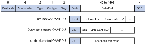
Table 1 Fields in an OAMPDU
|
Field |
Description |
|
Dest addr |
Destination MAC address of the Ethernet OAMPDU. It is a slow protocol multicast address 0180c2000002. Because bridges cannot forward slow protocol packets, Ethernet OAMPDUs cannot be forwarded. |
|
Source addr |
Source MAC address of the Ethernet OAMPDU. It is the bridge MAC address of the sending side and is a unicast MAC address. |
|
Type |
Type of the encapsulated protocol in the Ethernet OAMPDU. The value is 0x8809. |
|
Subtype |
The specific protocol being encapsulated in the Ethernet OAMPDU. The value is 0x03. |
|
Flags |
Status information of an Ethernet OAM entity. |
|
Code |
Type of the Ethernet OAMPDU |
|
|
NOTE: Throughout this document, a port with Ethernet OAM enabled is called an Ethernet OAM entity or an OAM entity. |
Table 2 Functions of different types of OAMPDUs
|
OAMPDU type |
Function |
|
Information OAMPDU |
Used for transmitting state information of an Ethernet OAM entity (including information about the local and remote devices, and customized information) to the remote Ethernet OAM entity, and maintaining OAM connections. |
|
Event Notification OAMPDU |
Used by link monitoring to notify the remote OAM entity when it detects problems on the link in between. |
|
Loopback Control OAMPDU |
Used for remote loopback control. By inserting the information used to enable/disable loopback to a loopback control OAMPDU, you can enable/disable loopback on a remote OAM entity. |
How Ethernet OAM works
This section describes the working procedures of Ethernet OAM.
Ethernet OAM connection establishment
Ethernet OAM connection is the basis of all the other Ethernet OAM functions. OAM connection establishment is also known as the “Discovery phase”, where an Ethernet OAM entity discovers remote OAM entities and establishes sessions with them.
In this phase, interconnected OAM entities determine whether Ethernet OAM connections can be established, by exchanging Information OAMPDUs to notify the peer of their OAM configuration information and the OAM capabilities of the local nodes. An Ethernet OAM connection can be established between entities that have matching Loopback, link detecting, and link event settings. After an Ethernet OAM connection is established, Ethernet OAM takes effect on both sides.
For Ethernet OAM connection establishment, a switch can operate in active or passive Ethernet OAM mode, but a switch role will be somewhat different depending on the mode. Table 3 compares the two modes.
Table 3 Active Ethernet OAM mode and passive Ethernet OAM mode
|
Item |
Active Ethernet OAM mode |
Passive Ethernet OAM mode |
|
Initiating OAM Discovery |
Available |
Unavailable |
|
Responding to OAM Discovery |
Available |
Available |
|
Transmitting Information OAMPDUs |
Available |
Available |
|
Transmitting Event Notification OAMPDUs |
Available |
Available |
|
Transmitting Information OAMPDUs without any TLV |
Available |
Available |
|
Transmitting Loopback Control OAMPDUs |
Available |
Unavailable |
|
Responding to Loopback Control OAMPDUs |
Available (if both sides operate in active OAM mode) |
Available |
|
|
NOTE: · Only OAM entities operating in active OAM mode can initiate OAM connections, and those operating in passive mode wait and respond to the connection requests sent by their peers. · No OAM connection can be established between OAM entities operating in passive OAM mode. |
After an Ethernet OAM connection is established, the Ethernet OAM entities on both sides exchange Information OAMPDUs at a specified interval (called a handshake packet transmission interval) to check whether the Ethernet OAM connection is normal. If an Ethernet OAM entity receives no Information OAMPDU within the Ethernet OAM connection timeout time, the Ethernet OAM connection is considered disconnected.
Link monitoring
Error detection in an Ethernet is difficult, especially when the physical connection in the network is not disconnected but network performance is degrading gradually. Link monitoring is used to detect and indicate link faults in various environments. Ethernet OAM implements link monitoring through the exchange of Event Notification OAMPDUs. On detecting one of the link error events listed in Table 4, the local OAM entity sends an Event Notification OAMPDU to notify the remote OAM entity. With the log information, network administrators can keep track of network status promptly.
Table 4 Ethernet OAM link error events
|
Ethernet OAM link events |
Description |
|
Errored symbol event |
An errored symbol event occurs when the number of detected symbol errors during a specified detection interval exceeds the predefined threshold. |
|
Errored frame event |
An errored frame event occurs when the number of detected error frames during a specified interval exceeds the predefined threshold. |
|
Errored frame period event |
An errored frame period event occurs when the number of frame errors in the specified number of received frames exceeds the predefined threshold. |
|
Errored frame seconds event |
An errored frame seconds event occurs when the number of error frame seconds detected on a port during a specified interval reaches the error threshold. |
|
|
NOTE: · The system transforms the period of detecting errored frame period events into the maximum number of 64-byte frames (excluding interframe spacing and preamble) that a port can send in the specified period, that is, the system takes the maximum number of frames sent as the period. The maximum number of frames sent is calculated using this formula: the maximum number of frames = interface bandwidth (bps) × errored frame period event detection period (in ms)/(64 × 8 × 1000) · A second in which errored frames appear is called an “errored frame second.” |
Remote fault detection
Information OAMPDUs are exchanged periodically among Ethernet OAM entities across established OAM connections. In a network where traffic is interrupted due to device failures or unavailability, the flag field defined in information OAMPDUs allows an Ethernet OAM entity to send error information (the critical link event type) to its peer. You can use the log information to track ongoing link status and troubleshoot problems promptly. Table 5 lists critical link events and the transmission frequencies of the corresponding OAMPDUs.
|
Type |
Description |
OAMPDU transmission frequencies |
|
Link Fault |
Peer link signal is lost. |
Once per second |
|
Dying Gasp |
An unexpected error, such as power failure, occurred. |
Non-stop |
|
Critical event |
An undetermined critical event occurred. |
Non-stop |
|
|
NOTE: The support of H3C switches for information OAMPDUs carrying critical link events is as follows: · H3C switches are able to receive information OAMPDUs carrying the critical link events listed in Table 5. · H3C devices are able to send information OAMPDUs carrying Dying Gasp events when the device is rebooted or relevant ports are manually shut down. Physical IRF ports, however, are unable to send this type of OAMPDUs. For more information about physical IRF ports, see IRF Configuration Guide. · H3C switches are unable to send information OAMPDUs carrying Critical Events. |
Remote loopback
Remote loopback is available only after the Ethernet OAM connection is established. With remote loopback enabled, the Ethernet OAM entity operating in active Ethernet OAM mode sends non-OAMPDUs to its peer. After receiving these frames, the peer does not forward them according to their destination addresses. Instead, it returns them to the sender along the original path.
Remote loopback enables you to check the link status and locate link failures. Performing remote loopback periodically helps to detect network faults promptly. Furthermore, performing remote loopback by network segments helps to locate network faults.
Standards and protocols
Ethernet OAM is defined in IEEE 802.3ah (Carrier Sense Multiple Access with Collision Detection (CSMA/CD) Access Method and Physical Layer Specifications.
Ethernet OAM configuration task list
Complete the following tasks to configure Ethernet OAM:
|
Task |
Remarks |
|
|
Required |
||
|
Optional |
||
|
Optional |
||
|
Optional |
||
|
Optional |
||
|
Optional |
||
|
Rejecting the Ethernet OAM remote loopback request from a remote port |
||
Configuring basic Ethernet OAM functions
An Ethernet OAM entity operates in active or passive mode to establish Ethernet OAM connections. Only an Ethernet OAM entity in active mode can initiate connection establishment. After Ethernet OAM is enabled on an Ethernet port, according to its Ethernet OAM mode, the Ethernet port establishes an Ethernet OAM connection with its peer port.
|
|
CAUTION: To change the Ethernet OAM mode on an Ethernet OAM-enabled port, you must first disable Ethernet OAM on the port. |
To configure basic Ethernet OAM functions:
|
Step |
Command |
Remarks |
|
1. Enter system view. |
system-view |
N/A |
|
2. Enter Layer 2 Ethernet port view. |
interface interface-type interface-number |
N/A |
|
3. Set Ethernet OAM mode. |
oam mode { active | passive } |
Optional. The default is active Ethernet OAM mode. |
|
4. Enable Ethernet OAM on the current port. |
oam enable |
Ethernet OAM is disabled by default. |
Configuring the Ethernet OAM connection detection timers
After an Ethernet OAM connection is established, the Ethernet OAM entities on both sides exchange Information OAMPDUs at a specified interval (called the handshake packet transmission interval) to check whether the Ethernet OAM connection is normal. If an Ethernet OAM entity receives no Information OAMPDU within the Ethernet OAM connection timeout time, the Ethernet OAM connection is considered disconnected.
By adjusting the handshake packet transmission interval and the connection timeout timer, you can change the detection time resolution for Ethernet OAM connections.
To configure the Ethernet OAM connection detection timers:
|
Step |
Command |
Remarks |
|
1. Enter system view. |
system-view |
N/A |
|
2. Configure the Ethernet OAM handshake packet transmission interval. |
oam timer hello interval |
Optional 1000 millisecond by default |
|
3. Configure the Ethernet OAM connection timeout timer. |
oam timer keepalive interval |
Optional 5000 milliseconds by default |
|
|
CAUTION: After the timeout timer of an Ethernet OAM connection expires, the local OAM entity ages out its connection with the peer OAM entity, causing the OAM connection to be disconnected. H3C recommends that you set the connection timeout timer at least five times the handshake packet transmission interval, ensuring the stability of Ethernet OAM connections. |
Configuring link monitoring
|
|
NOTE: After Ethernet OAM connections are established, the link monitoring periods and thresholds configured in this section take effect on all Ethernet ports automatically. |
Configuring errored frame event detection
To configure errored frame event detection:
|
Step |
Command |
Remarks |
|
1. Enter system view. |
system-view |
N/A |
|
2. Configure the errored frame event detection interval. |
oam errored-frame period period-value |
Optional 1 second by default |
|
3. Configure the errored frame event triggering threshold. |
oam errored-frame threshold threshold-value |
Optional 1 by default |
Configuring errored frame period event detection
To configure errored frame period event detection:
|
Step |
Command |
Remarks |
|
1. Enter system view. |
system-view |
N/A |
|
2. Configure the errored frame period event detection period. |
oam errored-frame-period period period-value |
Optional 1000 milliseconds by default |
|
3. Configure the errored frame period event triggering threshold. |
oam errored-frame-period threshold threshold-value |
Optional 1 by default |
Configuring errored frame seconds event detection
To configure errored frame seconds event detection:
|
Step |
Command |
Remarks |
|
1. Enter system view. |
system-view |
N/A |
|
2. Configure the errored frame seconds event detection interval. |
oam errored-frame-seconds period period-value |
Optional 60 second by default |
|
3. Configure the errored frame seconds event triggering threshold. |
oam errored-frame-seconds threshold threshold-value |
Optional 1 by default |
|
|
CAUTION: Make sure the errored frame seconds triggering threshold is less than the errored frame seconds detection interval. Otherwise, no errored frame seconds event can be generated. |
Enabling OAM remote loopback
Enabling Ethernet OAM remote loopback
When you enable Ethernet OAM remote loopback on a port, the port sends Loopback Control OAMPDUs to a remote port, and the remote port enters the loopback state. The port then sends test frames to the remote port. By observing how many of these test frames return, you can calculate the packet loss ratio on the link and evaluate the link performance.
You can enable Ethernet OAM remote loopback on a specific port in user view, system view, or Layer 2 Ethernet port view. The configuration effects are the same.
To enable Ethernet OAM remote loopback in user view:
|
Task |
Command |
Remarks |
|
Enable Ethernet OAM remote loopback on a specific port. |
oam loopback interface interface-type interface-number |
Disabled by default |
To enable Ethernet OAM remote loopback in system view:
|
Step |
Command |
Remarks |
|
1. Enter system view. |
system-view |
N/A |
|
2. Enable Ethernet OAM remote loopback on a specific port. |
oam loopback interface interface-type interface-number |
Disabled by default |
To enable Ethernet OAM remote loopback in Layer 2 Ethernet port view:
|
Step |
Command |
Remarks |
|
1. Enter system view. |
system-view |
N/A |
|
2. Enter Layer 2 Ethernet port view. |
interface interface-type interface-number |
N/A |
|
3. Enable Ethernet OAM remote loopback on the port. |
oam loopback |
Disabled by default |
|
|
CAUTION: Because enabling Ethernet OAM remote loopback impacts other services, use this function with caution. |
|
|
NOTE: · Ethernet OAM remote loopback is available only after the Ethernet OAM connection is established and can be performed only by Ethernet OAM entities operating in active Ethernet OAM mode. · Remote loopback is available only on full-duplex links that support remote loopback at both ends. · Ethernet OAM remote loopback must be supported by both the remote port and the sending port. · Enabling Ethernet OAM remote loopback interrupts data communications. After Ethernet OAM remote loopback is disabled, all the ports involved will shut down and then come up. Ethernet OAM remote loopback can be disabled by any of the following events: executing the undo oam enable command to disable Ethernet OAM, executing the undo oam loopback interface or undo oam loopback command to disable Ethernet OAM remote loopback, and Ethernet OAM connection timing out. · Ethernet OAM remote loopback is only applicable to individual links. It is not applicable to link aggregation member ports. In addition, you cannot assign ports where Ethernet OAM remote loopback is being performed to link aggregation groups. For more information about link aggregation groups, see Layer 2—LAN Switching Configuration Guide. · Enabling internal loopback test on a port in remote loopback test can terminate the remote loopback test. For more information about loopback test, see Interface Configuration Guide. |
Rejecting the Ethernet OAM remote loopback request from a remote port
The Ethernet OAM remote loopback function impacts other services. To solve this problem, you can disable a port from being controlled by the Loopback Control OAMPDUs sent by a remote port. The local port then rejects the Ethernet OAM remote loopback request from the remote port.
To reject the Ethernet OAM remote loopback request from a remote port:
|
Step |
Command |
Remarks |
|
1. Enter system view. |
system-view |
N/A |
|
2. Enter Layer 2 Ethernet port view. |
interface interface-type interface-number |
N/A |
|
3. Reject the Ethernet OAM remote loopback request from a remote port. |
oam loopback reject-request |
By default, a port does not reject the Ethernet OAM remote loopback request from a remote port. |
Displaying and maintaining Ethernet OAM configuration
|
Task |
Command |
Remarks |
|
Display global Ethernet OAM configuration. |
display oam configuration [ | { begin | exclude | include } regular-expression ] |
Available in any view |
|
Display the statistics on critical events after an Ethernet OAM connection is established. |
display oam critical-event [ interface interface-type interface-number ] [ | { begin | exclude | include } regular-expression ] |
Available in any view |
|
Display the statistics on Ethernet OAM link error events after an Ethernet OAM connection is established. |
display oam link-event { local | remote } [ interface interface-type interface-number ] [ | { begin | exclude | include } regular-expression ] |
Available in any view |
|
Display the information about an Ethernet OAM connection. |
display oam { local | remote } [ interface interface-type interface-number ] [ | { begin | exclude | include } regular-expression ] |
Available in any view |
|
Clear statistics on Ethernet OAM packets and Ethernet OAM link error events. |
reset oam [ interface interface-type interface-number ] |
Available in user view only |
Ethernet OAM configuration example
Network requirements
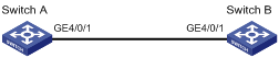
On the network shown in Figure 2:
· Enable Ethernet OAM on Switch A and Switch B to auto-detect link errors between the two switches.
· Monitor the performance of the link between Switch A and Switch B by collecting statistics about the error frames received by Switch A.
Configuration procedure
1. Configure Switch A.
# Configure GigabitEthernet 4/0/1 to operate in passive Ethernet OAM mode and enable Ethernet OAM for it.
<SwitchA> system-view
[SwitchA] interface gigabitethernet 4/0/1
[SwitchA-GigabitEthernet4/0/1] oam mode passive
[SwitchA-GigabitEthernet4/0/1] oam enable
[SwitchA-GigabitEthernet4/0/1] quit
# Set the errored frame detection interval to 20 seconds and set the errored frame event triggering threshold to 10.
[SwitchA] oam errored-frame period 20
[SwitchA] oam errored-frame threshold 10
2. Configure Switch B.
# Configure GigabitEthernet 4/0/1 to operate in active Ethernet OAM mode (the default) and enable Ethernet OAM for it.
<SwitchB> system-view
[SwitchB] interface gigabitethernet 4/0/1
[SwitchB-GigabitEthernet4/0/1] oam mode active
[SwitchB-GigabitEthernet4/0/1] oam enable
[SwitchB-GigabitEthernet4/0/1] quit
3. Verify the configuration.
Use the display oam configuration command to display the Ethernet OAM configuration. For example:
# Display the Ethernet OAM information on Switch A.
[SwitchA] display oam configuration
Configuration of the link event window/threshold :
--------------------------------------------------------------------------
Errored-symbol Event period(in seconds) : 1
Errored-symbol Event threshold : 1
Errored-frame Event period(in seconds) : 20
Errored-frame Event threshold : 10
Errored-frame-period Event period(in ms) : 1000
Errored-frame-period Event threshold : 1
Errored-frame-seconds Event period(in seconds) : 60
Errored-frame-seconds Event threshold : 1
Configuration of the timer :
--------------------------------------------------------------------------
Hello timer(in ms) : 1000
Keepalive timer(in ms) : 5000
According to the above output information, the detection period of errored frame events is 20 seconds, the detection threshold is 10 seconds, and all the other parameters use the default values.
# Display the statistics of Ethernet OAM critical link events on all the ports of Switch A.
[SwitchA] display oam critical-event
Port : GigabitEthernet4/0/1
Link Status : Up
Event statistic :
-------------------------------------------------------------------------
Link Fault :0 Dying Gasp : 0 Critical Event : 0
According to the above output information, no critical link event occurred on the link between Switch A and Switch B.
# Display Ethernet OAM link event statistics of the remote end of Switch B.
[SwitchB] display oam link-event remote
Port :GigabitEthernet4/0/1
Link Status :Up
OAMRemoteErrFrameEvent : (ms = milliseconds)
---------------------------------------------------------------------
Event Time Stamp : 5789 Errored FrameWindow : 10(100ms)
Errored Frame Threshold : 1 Errored Frame : 3
Error Running Total : 35 Event Running Total : 17
The output shows that 35 errors occurred since Ethernet OAM is enabled on Switch A, 17 of which are caused by error frames. The link is instable.
