- Table of Contents
-
- 07-Layer 3 - IP Routing Configuration Guide
- 00-Preface
- 01-IP Routing Basics
- 02-Static Routing Configuration
- 03-RIP Configuration
- 04-OSPF Configuration
- 05-IS-IS Configuration
- 06-BGP Configuration
- 07-Policy-Based Routing Configuration
- 08-Guard Route Configuration
- 09-IPv6 Static Routing Configuration
- 10-RIPng Configuration
- 11-OSPFv3 Configuration
- 12-IPv6 IS-IS Configuration
- 13-IPv6 BGP Configuration
- 14-IPv6 Policy-Based Routing Configuration
- 15-Routing Policy Configuration
- 16-Tunnel End Packets Policy Routing Configuration
- Related Documents
-
| Title | Size | Download |
|---|---|---|
| 12-IPv6 IS-IS Configuration | 184.91 KB |
Configuring IPv6 IS-IS basic functions
Configuring IPv6 IS-IS routing information control
Configuring BFD for IPv6 IS-IS
Displaying and maintaining IPv6 IS-IS
IPv6 IS-IS configuration examples
IPv6 IS-IS basic configuration example
|
|
NOTE: IPv6 IS-IS supports all the features of IPv4 IS-IS except that it advertises IPv6 routing information instead. This document describes only IPv6 IS-IS exclusive configuration tasks. For other configuration tasks, see the chapter “Configuring IS-IS.” |
Introduction to IPv6 IS-IS
The IS-IS routing protocol (Intermediate System-to-Intermediate System intra-domain routing information exchange protocol) supports multiple network protocols, including IPv6. IS-IS with IPv6 support is called IPv6 IS-IS dynamic routing protocol. The international engineer task force (IETF) defines two type-length-values (TLVs) and a new network layer protocol identifier (NLPID) to enable IPv6 support for IS-IS.
TLV is a variable-length field in the link state PDU or link state packet (LSP). The TLVs are as follows:
· IPv6 Reachability—Defines the prefix, metric of routing information to indicate network reachability, and has a type value of 236 (0xEC).
· IPv6 Interface Address—Same as the “IP Interface Address” TLV in IPv4 ISIS, except that the 32-bit IPv4 address is translated to the 128-bit IPv6 address.
The NLPID is an 8-bit field that identifies which network layer protocol is supported. For IPv6, the NLPID is 142 (0x8E), which must be carried in hello packets sent by a router that supports IPv6 IS-IS.
For information about IS-IS, see the chapter “Configuring IS-IS.”
Configuring IPv6 IS-IS basic functions
|
|
NOTE: You can implement IPv6 inter-networking through configuring IPv6 IS-IS in IPv6 network environment. |
Configuration prerequisites
Before you configure IPv6 IS-IS basic functions, complete the following tasks:
· Enable IPv6 globally.
· Configure IP addresses for interfaces, and make sure that all neighboring nodes are reachable.
· Enable IS-IS.
Configuration procedure
To configure the basic functions of IPv6 IS-IS:
|
Step |
Command |
Remarks |
|
1. Enter system view. |
system-view |
N/A |
|
2. Enable an IS-IS process and enter IS-IS view. |
isis [ process-id ] |
Disabled by default |
|
3. Configure the network entity title for the IS-IS process. |
network-entity net |
Not configured by default |
|
4. Enable IPv6 for the IS-IS process. |
ipv6 enable |
Disabled by default |
|
5. Return to system view. |
quit |
N/A |
|
6. Enter interface view. |
interface interface-type interface-number |
N/A |
|
7. Enable IPv6 for an IS-IS process on the interface. |
isis ipv6 enable [ process-id ] |
Disabled by default |
Configuring IPv6 IS-IS routing information control
Configuration prerequisites
Complete the IPv6 IS-IS basic function configuration before you configure this task.
Configuration procedure
To configure IPv6 IS-IS routing information control:
|
Step |
Command |
Remarks |
|
1. Enter system view. |
system-view |
N/A |
|
2. Enter IS-IS view. |
isis [ process-id ] |
N/A |
|
3. Define the priority for IPv6 IS-IS routes. |
ipv6 preference { route-policy route-policy-name | preference } * |
Optional. 15 by default. |
|
4. Configure an IPv6 IS-IS summary route. |
ipv6 summary ipv6-prefix prefix-length [ avoid-feedback | generate_null0_route | [ level-1 | level-1-2 | level-2 ] | tag tag ] * |
Optional. Not configured by default. |
|
5. Generate an IPv6 IS-IS default route. |
ipv6 default-route-advertise [ [ level-1 | level-1-2 | level-2 ] | route-policy route-policy-name ]* |
Optional. By default, no IPv6 default route is defined. |
|
6. Configure IPv6 IS-IS to filter incoming routes. |
ipv6 filter-policy { acl6-number | ipv6-prefix ipv6-prefix-name | route-policy route-policy-name } import |
Optional By default, no filtering policy is defined. |
|
7. Configure IPv6 IS-IS to redistribute routes from another routing protocol. |
ipv6 import-route protocol [ process-id ] [ allow-ibgp ] [ cost cost | [ level-1 | level-1-2 | level-2 ] | route-policy route-policy-name | tag tag ]* |
Optional. Not configured by default. |
|
8. Configure the maximum number of redistributed Level 1/Level 2 IPv6 routes. |
ipv6 import-route limit number |
Optional. |
|
9. Configure the filtering of outgoing redistributed routes. |
ipv6 filter-policy { acl6-number | ipv6-prefix ipv6-prefix-name | route-policy route-policy-name } export [ protocol [ process-id ] ] |
Optional. Not configured by default. |
|
10. Enable route leaking. |
ipv6 import-route isisv6 level-2 into level-1 [ filter-policy { acl6-number | ipv6-prefix ipv6-prefix-name | route-policy route-policy-name } | tag tag ] * |
Optional. Disabled by default. |
|
11. Specify the maximum number of equal-cost load balanced routes. |
ipv6 maximum load-balancing number |
Optional. 16 by default. |
|
|
NOTE: · The ipv6 filter-policy export command is usually used in combination with the ipv6 import-route command. If no protocol is specified for the ipv6 filter-policy export command, routes redistributed from all routing protocols are filtered before advertisement. If a protocol is specified, only routes redistributed from the routing protocol are filtered before advertisement. · For information about ACL, see ACL and QoS Configuration Guide. · For information about routing policy and IPv6 prefix list, see the chapter “Configuring routing policy.” |
Configuring BFD for IPv6 IS-IS
Bidirectional forwarding detection (BFD) provides a mechanism to quickly detect the connectivity of links between IPv6 IS-IS neighbors, thus to improve the convergence speed of IPv6 IS-IS.
To configure BFD for IPv6 IS-IS:
|
Step |
Command |
Remarks |
|
1. Enter system view. |
system-view |
N/A |
|
2. Enable an IS-IS process and enter IS-IS view. |
isis [ process-id ] |
N/A |
|
3. Configure the network entity title for the IS-IS process. |
network-entity net |
Not configured by default |
|
4. Enable IPv6 for the IS-IS process. |
ipv6 enable |
Disabled by default |
|
5. Return to system view. |
quit |
N/A |
|
6. Enter interface view. |
interface interface-type interface-number |
N/A |
|
7. Enable IPv6 for an IS-IS process on the interface. |
isis ipv6 enable [ process-id ] |
Disabled by default |
|
8. Enable BFD on the interface. |
isis ipv6 bfd enable |
Disabled by default |
|
|
NOTE: For more information about BFD, see High Availability Configuration Guide. |
Configuring IPv6 IS-IS MTR
Configuration guidelines
On a network comprising both IPv4 and IPv6 topologies, the IPv4 and IPv6 topologies must be consistent so that both IPv6 IS-IS and IPv4 IS-IS can use the Shortest Path First (SPF) algorithm to perform route calculation. If they are different, routers supporting both IPv4 and IPv6 send IPv6 packets to routers that do not support IPv6, and thus packet loss occurs.
To solve the problem, you can configure IPv6 IS-IS Multi-Topology Routing (MTR) to perform route calculation separately in IPv4 and IPv6 topologies.
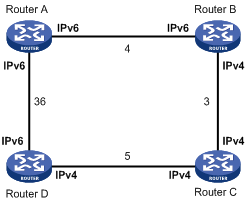
In Figure 1, the numbers refer to the link costs. Router A, Router B, and Router D support both IPv4 and IPv6. Router C supports only IPv4 and cannot forward IPv6 packets.
Enable IPv6 IS-IS MTR on Router A, Router B, Router C, and Router D to make them perform route calculation separately in IPv4 and IPv6 topologies. In this way, Router A will not forward IPv6 packets destined to Router D through Router B to avoid packet loss.
Configuration prerequisites
Before you configure IPv6 IS-IS MTR, configure basic IS-IS functions, and establish IS-IS neighbors.
Configuration procedure
To configure IPv6 IS-IS MTR:
|
Step |
Command |
Remarks |
|
1. Enter system view. |
system-view |
N/A |
|
2. Enter IS-IS view. |
isis [ process-id ] [ vpn-instance vpn-instance-name ] |
N/A |
|
3. Specify the cost style for IS-IS. |
cost-style { narrow | wide | wide-compatible | { compatible | narrow-compatible } [ relax-spf-limit ] } |
By default, narrow is adopted. |
|
4. Enable IPv6 IS-IS MTR. |
multiple-topology ipv6-unicast |
Disabled by default. |
Displaying and maintaining IPv6 IS-IS
|
Command |
Remarks |
|
|
Display brief IPv6 IS-IS information. |
display isis brief [ | { begin | exclude | include } regular-expression ] |
Available in any view |
|
Display the status of the debug switches. |
display isis debug-switches { process-id | vpn-instance vpn-instance-name } [ | { begin | exclude | include } regular-expression ] |
Available in any view |
|
Display IS-IS enabled interface information. |
display isis interface [ statistics | [ interface-type interface-number ] [ verbose ] ] [ process-id | vpn-instance vpn-instance-name ] [ | { begin | exclude | include } regular-expression ] |
Available in any view |
|
Display LSDB information. |
display isis lsdb [ [ l1 | l2 | level-1 | level-2 ] | [ [ lsp-id lsp-id | lsp-name lspname | local ] | verbose ] * ] * [ process-id | vpn-instance vpn-instance-name ] [ | { begin | exclude | include } regular-expression ] |
Available in any view |
|
Display IS-IS mesh group information. |
display isis mesh-group [ process-id | vpn-instance vpn-instance-name ] [ | { begin | exclude | include } regular-expression ] |
Available in any view |
|
Display the mapping table between the host name and system ID. |
display isis name-table [ process-id | vpn-instance vpn-instance-name ] [ | { begin | exclude | include } regular-expression ] |
Available in any view |
|
Display IS-IS neighbor information. |
display isis peer [ statistics | verbose ] [ process-id | vpn-instance vpn-instance-name ] [ | { begin | exclude | include } regular-expression ] |
Available in any view |
|
Display IPv6 IS-IS routing information. |
display isis route ipv6 [ [ level-1 | level-2 ] | verbose ]* [ process-id | vpn-instance vpn-instance-name ] [ | { begin | exclude | include } regular-expression ] |
Available in any view |
|
Display SPF log information. |
display isis spf-log [ process-id | vpn-instance vpn-instance-name ] [ | { begin | exclude | include } regular-expression ] |
Available in any view |
|
Display the statistics of the IS-IS process. |
display isis statistics [ level-1 | level-1-2 | level-2 ] [ process-id | vpn-instance vpn-instance-name ] [ | { begin | exclude | include } regular-expression ] |
Available in any view |
|
Clear all IS-IS data structure information. |
reset isis all [ process-id | vpn-instance vpn-instance-name ] |
Available in user view |
|
Clear the IS-IS data information of a neighbor. |
reset isis peer system-id [ process-id | vpn vpn-instance-name ] |
Available in user view |
IPv6 IS-IS configuration examples
|
|
NOTE: By default, Ethernet, VLAN, and aggregate interfaces are down. Before configuring these interfaces, bring them up by using the undo shutdown command. |
IPv6 IS-IS basic configuration example
Network requirements
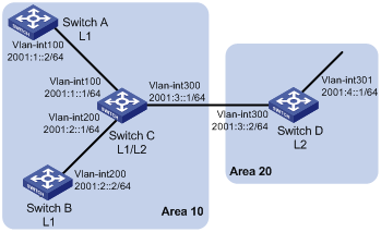
As shown in Figure 2, Switch A, Switch B, Switch C, and Switch D reside in the same autonomous system (AS), and all are enabled with IPv6.
Switch A and Switch B are Level-1 switches; Switch D is a Level-2 switch; and Switch C is a Level-1-2 switch. Switch A, Switch B, and Switch C are in area 10, while Switch D is in area 20.
Configuration procedure
1. Configure IPv6 addresses for interfaces. (Details not shown)
2. Configure IPv6 IS-IS:
# Configure Switch A.
<SwitchA> system-view
[SwitchA] ipv6
[SwitchA] isis 1
[SwitchA-isis-1] is-level level-1
[SwitchA-isis-1] network-entity 10.0000.0000.0001.00
[SwitchA-isis-1] ipv6 enable
[SwitchA-isis-1] quit
[SwitchA] interface Vlan-interface 100
[SwitchA-Vlan-interface100] isis ipv6 enable 1
[SwitchA-Vlan-interface100] quit
# Configure Switch B.
<SwitchB> system-view
[SwitchB] ipv6
[SwitchB] isis 1
[SwitchB-isis-1] is-level level-1
[SwitchB-isis-1] network-entity 10.0000.0000.0002.00
[SwitchB-isis-1] ipv6 enable
[SwitchB-isis-1] quit
[SwitchB] interface Vlan-interface 200
[SwitchB-Vlan-interface200] isis ipv6 enable 1
[SwitchB-Vlan-interface200] quit
# Configure Switch C.
<SwitchC> system-view
[SwitchC] ipv6
[SwitchC] isis 1
[SwitchC-isis-1] network-entity 10.0000.0000.0003.00
[SwitchC-isis-1] ipv6 enable
[SwitchC-isis-1] quit
[SwitchC] interface Vlan-interface 100
[SwitchC-Vlan-interface100] isis ipv6 enable 1
[SwitchC-Vlan-interface100] quit
[SwitchC] interface Vlan-interface 200
[SwitchC-Vlan-interface200] isis ipv6 enable 1
[SwitchC-Vlan-interface200] quit
[SwitchC] interface Vlan-interface 300
[SwitchC-Vlan-interface300] isis ipv6 enable 1
[SwitchC-Vlan-interface300] quit
# Configure Switch D.
<SwitchD> system-view
[SwitchD] ipv6
[SwitchD] isis 1
[SwitchD-isis-1] is-level level-2
[SwitchD-isis-1] network-entity 20.0000.0000.0004.00
[SwitchD-isis-1] ipv6 enable
[SwitchD-isis-1] quit
[SwitchD] interface Vlan-interface 300
[SwitchD-Vlan-interface300] isis ipv6 enable 1
[SwitchD-Vlan-interface300] quit
[SwitchD] interface Vlan-interface 301
[SwitchD-Vlan-interface301] isis ipv6 enable 1
[SwitchD-Vlan-interface301] quit
# Display the IPv6 IS-IS routing table of Switch A.
[SwitchA] display isis route ipv6
Route information for ISIS(1)
-----------------------------
ISIS(1) IPv6 Level-1 Forwarding Table
-------------------------------------
Destination: :: PrefixLen: 0
Flag : R/-/- Cost : 10
Next Hop : FE80::200:FF:FE0F:4 Interface: Vlan100
Destination: 2001:1:: PrefixLen: 64
Flag : D/L/- Cost : 10
Next Hop : Direct Interface: Vlan100
Destination: 2001:2:: PrefixLen: 64
Flag : R/-/- Cost : 20
Next Hop : FE80::200:FF:FE0F:4 Interface: Vlan100
Destination: 2001:3:: PrefixLen: 64
Flag : R/-/- Cost : 20
Next Hop : FE80::200:FF:FE0F:4 Interface: Vlan100
Flags: D-Direct, R-Added to RM, L-Advertised in LSPs, U-Up/Down Bit Set
# Display the IPv6 IS-IS routing table of Switch B.
[SwitchB] display isis route ipv6
Route information for ISIS(1)
-----------------------------
ISIS(1) IPv6 Level-1 Forwarding Table
-------------------------------------
Destination: :: PrefixLen: 0
Flag : R/-/- Cost : 10
Next Hop : FE80::200:FF:FE0F:4 Interface: Vlan200
Destination: 2001:1:: PrefixLen: 64
Flag : D/L/- Cost : 10
Next Hop : FE80::200:FF:FE0F:4 Interface: Vlan200
Destination: 2001:2:: PrefixLen: 64
Flag : R/-/- Cost : 20
Next Hop : Direct Interface: Vlan200
Destination: 2001:3:: PrefixLen: 64
Flag : R/-/- Cost : 20
Next Hop : FE80::200:FF:FE0F:4 Interface: Vlan200
Flags: D-Direct, R-Added to RM, L-Advertised in LSPs, U-Up/Down Bit Set
# Display the IPv6 IS-IS routing table of Switch C.
[SwitchC] display isis route ipv6
Route information for ISIS(1)
-----------------------------
ISIS(1) IPv6 Level-1 Forwarding Table
-------------------------------------
Destination: 2001:1:: PrefixLen: 64
Flag : D/L/- Cost : 10
Next Hop : Direct Interface: Vlan100
Destination: 2001:2:: PrefixLen: 64
Flag : D/L/- Cost : 10
Next Hop : Direct Interface: Vlan200
Destination: 2001:3:: PrefixLen: 64
Flag : D/L/- Cost : 10
Next Hop : Direct Interface: Vlan300
Flags: D-Direct, R-Added to RM, L-Advertised in LSPs, U-Up/Down Bit Set
ISIS(1) IPv6 Level-2 Forwarding Table
-------------------------------------
Destination: 2001:1:: PrefixLen: 64
Flag : D/L/- Cost : 10
Next Hop : Direct Interface: Vlan100
Destination: 2001:2:: PrefixLen: 64
Flag : D/L/- Cost : 10
Next Hop : Direct Interface: Vlan200
Destination: 2001:3:: PrefixLen: 64
Flag : D/L/- Cost : 10
Next Hop : Direct Interface: Vlan300
Destination: 2001:4::1 PrefixLen: 128
Flag : R/-/- Cost : 10
Next Hop : FE80::20F:E2FF:FE3E:FA3D Interface: Vlan300
Flags: D-Direct, R-Added to RM, L-Advertised in LSPs, U-Up/Down Bit Set
# Display the IPv6 IS-IS routing table of Switch D.
[SwitchD] display isis route ipv6
Route information for ISIS(1)
-----------------------------
ISIS(1) IPv6 Level-2 Forwarding Table
-------------------------------------
Destination: 2001:1:: PrefixLen: 64
Flag : R/-/- Cost : 20
Next Hop : FE80::200:FF:FE0F:4 Interface: Vlan300
Destination: 2001:2:: PrefixLen: 64
Flag : R/-/- Cost : 20
Next Hop : FE80::200:FF:FE0F:4 Interface: Vlan300
Destination: 2001:3:: PrefixLen: 64
Flag : D/L/- Cost : 10
Next Hop : Direct Interface: Vlan300
Destination: 2001:4::1 PrefixLen: 128
Flag : D/L/- Cost : 0
Next Hop : Direct Interface: Loop1
Flags: D-Direct, R-Added to RM, L-Advertised in LSPs, U-Up/Down Bit Set
Configuring BFD for IS-IS
Network requirements
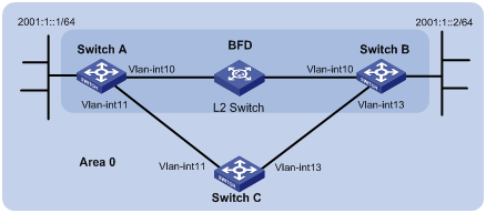
As shown in Figure 3, configure IPv6 IS-IS on Switch A, Switch B and Switch C and configure BFD over the link Switch A<—>L2 Switch<—>Switch B.
After the link between Switch B and the Layer-2 switch fails, BFD can quickly detect the failure and notify IPv6 IS-IS of the failure. Then Switch A and Switch B communicate through Switch C.
|
Device |
Interface |
IPv6 address |
Device |
Interface |
IPv6 address |
|
Switch A |
Vlan-int10 |
2001::1/64 |
Switch B |
Vlan-int10 |
2001::2/64 |
|
|
Vlan-int11 |
2001:2::1/64 |
|
Vlan-int13 |
2001:3::2/64 |
|
Switch C |
Vlan-int11 |
2001:2::2/64 |
|
|
|
|
|
Vlan-int13 |
2001:3::1/64 |
|
|
|
Configuration procedure
1. Configure IP addresses for interfaces. (Details not shown)
2. Configure IPv6 IS-IS:
# Configure Switch A.
<SwitchA> system-view
[SwitchA] ipv6
[SwitchA] isis 1
[SwitchA-isis-1] is-level level-1
[SwitchA-isis-1] network-entity 10.0000.0000.0001.00
[SwitchA-isis-1] ipv6 enable
[SwitchA-isis-1] quit
[SwitchA] interface vlan-interface 10
[SwitchA-Vlan-interface10] isis ipv6 enable 1
[SwitchA-Vlan-interface10] quit
[SwitchA] interface vlan-interface 11
[SwitchA-Vlan-interface11] isis ipv6 enable 1
[SwitchA-Vlan-interface11] quit
# Configure Switch B.
<SwitchB> system-view
[SwitchB] ipv6
[SwitchB] isis 1
[SwitchB-isis-1] is-level level-1
[SwitchB-isis-1] network-entity 10.0000.0000.0002.00
[SwitchB-isis-1] ipv6 enable
[SwitchB-isis-1] quit
[SwitchB] interface vlan-interface 10
[SwitchB-Vlan-interface10] isis ipv6 enable 1
[SwitchB-Vlan-interface10] quit
[SwitchB] interface vlan-interface 13
[SwitchB-Vlan-interface13] isis ipv6 enable 1
[SwitchB-Vlan-interface13] quit
# Configure Switch C.
<SwitchC> system-view
[SwitchC] ipv6
[SwitchC] isis 1
[SwitchC-isis-1] network-entity 10.0000.0000.0003.00
[SwitchC-isis-1] ipv6 enable
[SwitchC-isis-1] quit
[SwitchC] interface vlan-interface 11
[SwitchC-Vlan-interface11] isis ipv6 enable 1
[SwitchC-Vlan-interface11] quit
[SwitchC] interface vlan-interface 13
[SwitchC-Vlan-interface13] isis ipv6 enable 1
[SwitchC-Vlan-interface13] quit
3. Configure BFD functions:
# Enable BFD on Switch A and configure BFD parameters.
[SwitchA] bfd session init-mode active
[SwitchA] interface vlan-interface 10
[SwitchA-Vlan-interface10] isis ipv6 bfd enable
[SwitchA-Vlan-interface10] bfd min-transmit-interval 500
[SwitchA-Vlan-interface10] bfd min-receive-interval 500
[SwitchA-Vlan-interface10] bfd detect-multiplier 7
[SwitchA-Vlan-interface10] return
# Enable BFD on Switch B and configure BFD parameters.
[SwitchB] bfd session init-mode active
[SwitchB] interface vlan-interface 10
[SwitchB-Vlan-interface10] isis ipv6 bfd enable
[SwitchB-Vlan-interface10] bfd min-transmit-interval 500
[SwitchB-Vlan-interface10] bfd min-receive-interval 500
[SwitchB-Vlan-interface10] bfd detect-multiplier 6
4. Verify the configuration:
The following operations are made on Switch A. Operations for Switch B are similar. (Details not shown)
# Display the BFD information of Switch A.
<SwitchA> display bfd session
Total Session Num: 1 Init Mode: Active
IPv6 Session Working Under Ctrl Mode:
Local Discr: 1441 Remote Discr: 1450
Source IP: FE80::20F:FF:FE00:1202 (link-local address of VLAN-interface 10 on Switch A)
Destination IP: FE80::20F:FF:FE00:1200 (link-local address of VLAN-interface 10 on Switch B)
Session State: Up Interface: Vlan10
Hold Time: /
# Display route 2001:4::0/64 on Switch A, and you can see that Switch A and Switch B communicate through the Layer-2 switch.
<SwitchA> display ipv6 routing-table 2001:4::0 64 verbose
Routing Table :
Summary Count : 2
Destination : 2001:4::0 PrefixLength : 64
NextHop : 2001::2 Preference : 15
IpPrecedence : QosLcId :
RelayNextHop : :: Tag : 0H
Neighbor : :: ProcessID : 0
Interface : Vlan-interface10 Protocol : ISISv6
State : Active Adv Cost : 20
Tunnel ID : 0x0 Label : NULL
Age : 4538sec
Destination : 2001:4::0 PrefixLength : 64
NextHop : 2001:2::2 Preference : 15
IpPrecedence : QosLcId :
RelayNextHop : :: Tag : 0H
Neighbor : :: ProcessID : 0
Interface : Vlan-interface11 Protocol : ISISv6
State : Invalid Adv Cost : 30
Tunnel ID : 0x0 Label : NULL
Age : 4515sec
# Enable BFD debugging on Switch A.
<SwitchA> debugging bfd scm
<SwitchA> debugging bfd event
<SwitchA> debugging isis event bfd
<SwitchA> terminal debugging
# When the link between Switch B and the Layer-2 switch fails, BFD can quickly detect the failure.
#Aug 8 14:54:05:362 2009 SwitchA IFNET/4/INTERFACE UPDOWN:
Trap 1.3.6.1.6.3.1.1.5.3<linkDown>: Interface 983041 is Down, ifAdminStatus is
1, ifOperStatus is 2
#Aug 8 14:54:05:363 2009 SwitchA ISIS/4/ADJ_CHANGE:TrapID(1.3.6.1.2.1.138.0.17<
isisAdjacencyChange>), ISIS Level-2 Adjencency IN Circuit-983041 State Change.
#Aug 8 14:54:05:364 2009 SwitchA ISIS/4/ADJ_CHANGE:TrapID(1.3.6.1.2.1.138.0.17<
isisAdjacencyChange>), ISIS Level-1 Adjencency IN Circuit-983041 State Change.
%Aug 8 14:54:05:365 2009 SwitchA IFNET/4/LINK UPDOWN: vlan10: link status is DOWN
%Aug 8 14:54:05:366 2009 SwitchA IFNET/4/UPDOWN: Line protocol on the interface Vlan10 is DOWN
%Aug 8 14:54:05:367 2009 SwitchA ISIS/4/ADJLOG:ISIS-1-ADJCHANGE: Adjacency To 0000.0000.0002 (vlan10) DOWN, Level-2 Circuit Down.
%Aug 8 14:54:05:367 2009 SwitchA ISIS/4/ADJLOG:ISIS-1-ADJCHANGE: Adjacency To 0000.0000.0002 (vlan10) DOWN, Level-2 Adjacency clear.
%Aug 8 14:54:05:368 2009 SwitchA ISIS/4/ADJLOG:ISIS-1-ADJCHANGE: Adjacency To 0000.0000.0002 (vlan10) DOWN, Level-1 Circuit Down.
%Aug 8 14:54:05:369 2009 SwitchA ISIS/4/ADJLOG:ISIS-1-ADJCHANGE: Adjacency To 0000.0000.0002 (vlan10) DOWN, Level-1 Adjacency clear.
*Aug 8 14:54:05:369 2009 SwitchA ISIS/6/ISIS: ISIS-1-BFD: Recieve BFD session down . Type 0. DstIPAddr: FE80::20F:FF:FE00:1200 , SrcIPAddr: FE80::20F:FF:FE00:1202
*Aug 8 14:54:05:370 2009 SwitchA ISIS/6/ISIS: ISIS-1-BFD: Success to send msg. Msg type 1 delete session. IfPhyIndex: 5 , DstIPAddr: FE80::20F:FF:FE00:1200 , SrcIPAddr: FE80::20F:FF:FE00:1202. NeighborType:Level-1.
# Display the BFD information of Switch A. You can see that Switch A has removed its neighbor relationship with Switch B and therefore no information is output.
<SwitchA> display bfd session
# Display route 2001:4::0/64 on Switch A, and you can see that Switch A and Switch B communicate through Switch C.
<SwitchA> display ipv6 routing-table 2001:4::0 64 verbose
Routing Table :
Summary Count : 1
Destination : 2001:4::0 PrefixLength : 64
NextHop : 2001:2::2 Preference : 15
IpPrecedence : QosLcId :
RelayNextHop : :: Tag : 0H
Neighbor : :: ProcessID : 0
Interface : Vlan-interface11 Protocol : ISISv6
State : Active Adv Cost : 30
Tunnel ID : 0x0 Label : NULL
Age : 4610sec
