- Table of Contents
-
- 06-Layer 3 - IP Services Configuration Guide
- 00-Preface
- 01-ARP Configuration
- 02-IP Addressing Configuration
- 03-DHCP Configuration
- 04-DNS Configuration
- 05-NAT Configuration
- 06-IP Forwarding Basics Configuration
- 07-Adjacency Table Configuration
- 08-IP Performance Optimization Configuration
- 09-UDP Helper Configuration
- 10-IPv6 Basics Configuration
- 11-DHCPv6 Configuration
- 12-IPv6 DNS Configuration
- 13-Tunneling Configuration
- 14-GRE Configuration
- Related Documents
-
| Title | Size | Download |
|---|---|---|
| 03-DHCP Configuration | 649.83 KB |
Contents
Dynamic IP address allocation process
IP address allocation sequence
DHCP server configuration task list
Configuring an address pool for the DHCP server
Configuring an address allocation mode for a common address pool
Configuring dynamic address allocation for an extended address pool
Configuring a domain name suffix for the client
Configuring DNS servers for the client
Configuring WINS servers and NetBIOS node type for the client
Configuring BIMS server information for the client
Configuring gateways for the client
Configuring Option 184 parameters for the client with voice service
Configuring the TFTP server and bootfile name for the client
Specifying a server’s IP address for the DHCP client
Configuring self-defined DHCP options
Enabling the DHCP server on an interface
Applying an extended address pool on an interface
Configuring the DHCP server security functions
Enabling unauthorized DHCP server detection
Configuring IP address conflict detection
Configuring the DHCP server to support authorized ARP
Enabling client offline detection
Specifying the threshold for sending trap messages
Displaying and maintaining the DHCP server
DHCP server configuration examples
Static IP address assignment configuration example
Dynamic IP address assignment configuration example
Self-defined option configuration example
Troubleshooting DHCP server configuration
Introduction to DHCP relay agent
DHCP relay agent support for Option 82
DHCP relay agent configuration task list
Enabling the DHCP relay agent on an interface
Correlating a DHCP server group with a relay agent interface
Configuring the DHCP relay agent security functions
Configuring periodic refresh of dynamic client entries
Configuring the DHCP relay agent to support authorized ARP
Enabling unauthorized DHCP server detection
Enabling DHCP starvation attack protection
Enabling client offline detection
Configuring the DHCP relay agent to release an IP address
Configuring the DHCP relay agent to support Option 82
Displaying and maintaining the DHCP relay agent
DHCP relay agent configuration examples
DHCP relay agent configuration example
DHCP relay agent Option 82 support configuration example
Troubleshooting DHCP relay agent configuration
Enabling the DHCP client on an interface
Displaying and maintaining the DHCP client
DHCP client configuration example
Application environment of trusted ports
DHCP snooping support for Option 82
Configuring DHCP snooping basic functions
Configuring DHCP snooping to support Option 82
Configuring DHCP snooping entries backup
Enabling DHCP starvation attack protection
Enabling DHCP-request message attack protection
Displaying and maintaining DHCP snooping
DHCP snooping configuration examples
DHCP snooping configuration example
DHCP snooping Option 82 support configuration example
Introduction to DHCP
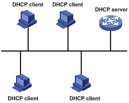
The Dynamic Host Configuration Protocol (DHCP) provides a framework to assign configuration information to network devices.
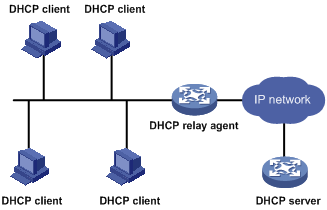
DHCP uses the client/server model. Figure 1 shows a typical DHCP application.
Figure 1 A typical DHCP application
DHCP address allocation
Allocation mechanisms
DHCP supports the following mechanisms for IP address allocation:
· Manual allocation—The network administrator assigns an IP address to a client such as a WWW server, and DHCP conveys the assigned address to the client.
· Automatic allocation—DHCP assigns a permanent IP address to a client.
· Dynamic allocation—DHCP assigns an IP address to a client for a limited period of time, which is called a lease. Most DHCP clients obtain their addresses in this way.
Dynamic IP address allocation process
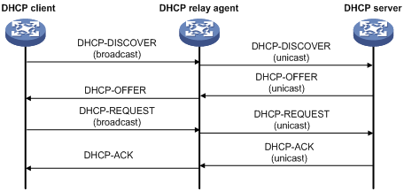
Figure 2 Dynamic IP address allocation process
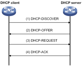
As shown in Figure 2, a DHCP client obtains an IP address from a DHCP server via four steps:
1. The client broadcasts a DHCP-DISCOVER message to locate a DHCP server.
2. A DHCP server offers configuration parameters such as an IP address to the client in a DHCP-OFFER message. The sending mode of the DHCP-OFFER is determined by the flag field in the DHCP-DISCOVER message. For related information, see “DHCP message format.”
3. If several DHCP servers send offers to the client, the client accepts the first received offer, and broadcasts it in a DHCP-REQUEST message to formally request the IP address.
4. All DHCP servers receive the DHCP-REQUEST message, but only the server from which the client accepts the offered IP address returns a DHCP-ACK message to the client, confirming that the IP address has been allocated to the client, or returns a DHCP-NAK unicast message, denying the IP address allocation.
|
|
NOTE: · After the client receives the DHCP-ACK message, it broadcasts a gratuitous ARP packet to verify whether the IP address assigned by the server is in use. If the client receives no response within the specified time, the client can use this IP address. Otherwise, the client sends a DHCP-DECLINE message to the server and requests an IP address again. · IP addresses offered by other DHCP servers are still assignable to other clients. |
IP address lease extension
The IP address dynamically allocated by a DHCP server to a client has a lease. When the lease expires, the IP address is reclaimed by the DHCP server. To continue using the IP address, the client must extend the lease duration.
After half the lease duration, the DHCP client sends a DHCP-REQUEST unicast to the DHCP server to extend the lease duration. Depending on availability of the IP address, the DHCP server returns a DHCP-ACK unicast confirming that the client’s lease duration has been extended, or a DHCP-NAK unicast denying the request.
If the client receives no reply, it broadcasts another DHCP-REQUEST for lease extension after 7/8 lease duration. Again, depending on availability of the IP address, the DHCP server returns a DHCP-ACK unicast confirming that the client’s lease has been extended, or a DHCP-NAK unicast denying the request.
DHCP message format
Figure 3 shows the DHCP message format, which is based on the BOOTP message format although DHCP uses some of the fields in significantly different ways. The numbers in parentheses indicate the size of each field in bytes.
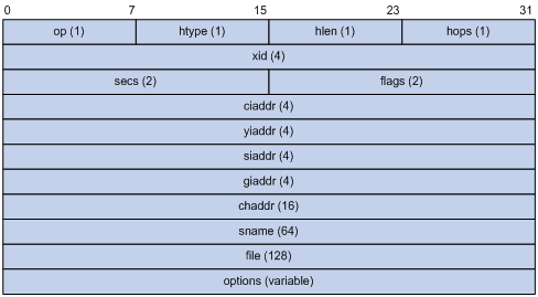
· op—Message type defined in option field. 1 = REQUEST, 2 = REPLY
· htype, hlen—Hardware address type and length of a DHCP client.
· hops—Number of relay agents a request message traveled.
· xid—Transaction ID, a random number chosen by the client to identify an IP address allocation.
· secs—Filled in by the client, the number of seconds elapsed since the client began address acquisition or renewal process. This field is reserved and set to 0.
· flags—The leftmost bit is defined as the BROADCAST (B) flag. If this flag is set to 0, the DHCP server sent a reply back by unicast; if this flag is set to 1, the DHCP server sent a reply back by broadcast. The remaining bits of the flags field are reserved for future use.
· ciaddr—Client IP address.
· yiaddr—'your' (client) IP address, assigned by the server.
· siaddr—Server IP address, from which the clients obtained configuration parameters.
· giaddr—IP address of the first relay agent a request message traveled.
· chaddr—Client hardware address.
· sname—The server host name, from which the client obtained configuration parameters.
· file—Bootfile name and path information, defined by the server to the client.
· options—Optional parameters field that is variable in length, which includes the message type, lease, domain name server IP address, and WINS IP address.
DHCP options
DHCP options overview
DHCP uses the same message format as BOOTP, but DHCP uses the Option field to carry information for dynamic address allocation and to provide additional configuration information to clients.
Introduction to DHCP options
The common DHCP options are as follows:
· Option 3—Router option. It specifies the gateway address to be assigned to the client.
· Option 6—DNS server option. It specifies the DNS server IP address to be assigned to the client.
· Option 33—Static route option. It specifies a list of classful static routes (the destination addresses in these static routes are classful.) that a client should add into its routing table. If both Option 33 and Option 121 exist, Option 33 is ignored.
· Option 51—IP address lease option.
· Option 53—DHCP message type option. It identifies the type of the DHCP message.
· Option 55—Parameter request list option. It is used by a DHCP client to request specified configuration parameters. The option contains values that correspond to the parameters requested by the client.
· Option 60—Vendor class identifier option. It is used by a DHCP client to identify its vendor, and by a DHCP server to distinguish DHCP clients by vendor class and assign specific IP addresses for the DHCP clients.
· Option 66—TFTP server name option. It specifies a TFTP server to be assigned to the client.
· Option 67—Bootfile name option. It specifies the bootfile name to be assigned to the client.
· Option 150—TFTP server IP address option. It specifies the TFTP server IP address to be assigned to the client.
· Option 121—Classless route option. It specifies a list of classless static routes (the destination addresses in these static routes are classless) that the requesting client should add into its routing table. If both Option 33 and Option 121 exist, Option 33 is ignored.
· Option 150—TFTP server IP address option. It specifies the TFTP server IP address to be assigned to the client.
For more information about DHCP options, see RFC 2132 and RFC 3442.
Self-defined options
Some options, such as Option 43, have no unified definitions in RFC 2132.
Vendor-specific option (Option 43)
DHCP servers and clients use Option 43 to exchange vendor-specific configuration information.
The DHCP client can obtain the following information through Option 43:
· Auto-Configuration Server (ACS) parameters, including the ACS URL, username, and password.
· Service provider identifier acquired by the customer premises equipment (CPE) from the DHCP server and sent to the ACS for selecting vender-specific configurations and parameters.
· Preboot Execution Environment (PXE) server address for further obtaining the bootfile or other control information from the PXE server.
1. Format of Option 43
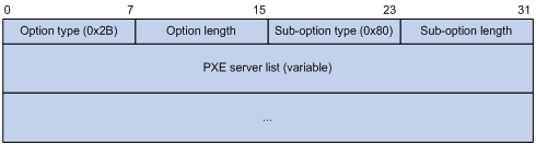
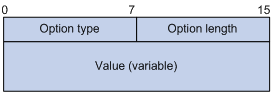
Network configuration parameters are carried in different sub-options of Option 43 as shown in Figure 5. The sub-option fields are described as follows:
¡ Sub-option type—Type of a sub-option. The field value can be 0x01, 0x02, or 0x80. 0x01 indicates an ACS parameter sub-option. 0x02 indicates a service provider identifier sub-option. 0x80 indicates a PXE server address sub-option.
¡ Sub-option length—Length of a sub-option excluding the sub-option type and sub-option length fields.
¡ Sub-option value—Value of a sub-option. The value format varies with sub-options.
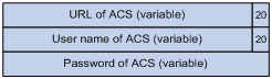
2. Format of the sub-option value field of Option 43
¡ As shown in Figure 6, the value field of the ACS parameter sub-option is filled in with variable ACS URL, username, and password separated with a space (0x20) in between.
Figure 6 Format of the value field of the ACS parameter sub-option
¡ The value field of the service provider identifier sub-option contains the service provider identifier.
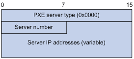
¡ Figure 7 shows the format of the value field of the PXE server address sub-option. The value of the PXE server type can only be 0. The server number field indicates the number of PXE servers contained in the sub-option. The server IP addresses filed contains the IP addresses of the PXE servers.
Figure 7 Format of the value field of the PXE server address sub-option
Relay agent option (Option 82)
Option 82 is the relay agent option in the option field of the DHCP message. It records the location information of the DHCP client. When a DHCP relay agent or DHCP snooping switch receives a client’s request, it adds Option 82 to the request message and sends it to the server.
The administrator can locate the DHCP client to further implement security control and accounting. The Option 82 supporting server can also use such information to define individual assignment policies of IP address and other parameters for the clients.
Option 82 involves at most 255 sub-options. At least one sub-option must be defined. The DHCP relay agent supports three sub-options: sub-option 1 (Circuit ID), sub-option 2 (Remote ID), and sub-option 9 (private padding format).
Option 82 has no unified definition. Its padding formats vary with vendors.
There are two methods for configuring Option 82:
· User-defined method—Manually specify the content of Option 82.
· Non-user-defined method—Pad Option 82 in the default normal or verbose format, private format, or standard format.
If you choose the second method, you can specify the code type for the sub-options as ASCII or HEX.
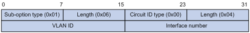
1. Normal padding format
The padding contents for sub-options in the normal padding format are as follows:
¡ Sub-option 1—Contains the VLAN ID and interface number of the interface that received the client’s request. The value of the sub-option type is 1, and that of the circuit ID type is 0.
Figure 8 Sub-option 1 in normal padding format
¡ Sub-option 2—Contains the MAC address of the DHCP relay agent interface or the MAC address of the DHCP snooping switch that received the client’s request. The value of the sub-option type is 2, and that of the remote ID type is 0.
Figure 9 Sub-option 2 in normal padding format
2. Verbose padding format:
The padding contents for sub-options in the verbose padding format are:
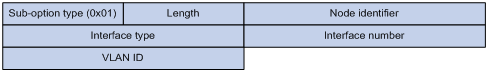
¡ Sub-option 1—Contains the user-specified access node identifier (ID of the switch that adds Option 82 in DHCP messages), and type, number, and VLAN ID of the interface that received the client’s request.
Figure 10 Sub-option 1 in verbose padding format
|
|
NOTE: The VLAN ID field has a fixed length of 2 bytes. All the other padding contents of sub-option 1 are length variable. See Figure 10. |
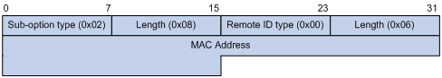
¡ Sub-option 2—Contains the MAC address of the DHCP relay agent interface or the MAC address of the DHCP snooping switch that received the client’s request. It has the same format as that in normal padding format. See Figure 9.
3. Private padding format
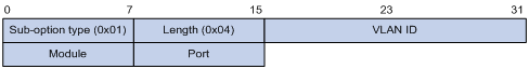
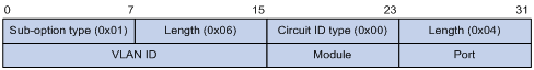
¡ Sub-option 1—Contains the VLAN ID of the interface that received the client’s request, module (subcard number of the receiving port on a centralized device or slot number of the receiving port on a distributed device) and port (port number of the receiving port). The value of the sub-option type is 1.
Figure 11 Sub-option 1 in Private padding format
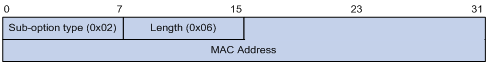
¡ Sub-option 2—Contains the MAC address of the DHCP relay agent interface or the MAC address of the DHCP snooping device that received the client’s request. The value of the sub-option type is 2.
Figure 12 Sub-option 2 in Private padding format
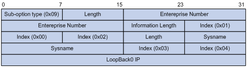
¡ Sub-option 9—Contains the sysname and the primary IP address of the Loopback0 interface. The value of the sub-option type is 9.
Figure 13 Sub-option 9 in Private padding format
4. Standard padding format
¡ Sub-option 1—Contains the VLAN ID of the interface that received the client’s request, module (subcard number of the receiving port on a centralized device or slot number of the receiving port on a distributed device) and port (port number of the receiving port). The value of the sub-option type is 1, and the value of the circuit ID type is 0.
Figure 14 Sub-option 1 in standard padding format
¡ Sub-option 2—Contains the MAC address of the DHCP relay agent interface or the MAC address of the DHCP snooping device that received the client’s request. The value of the sub-option type is 2, and that of the remote ID type is 0. It has the same format as sub-option 2 in normal padding format. See Figure 9.
Option 184
Option 184 is a reserved option, and parameters in the option can be defined as needed. The switch supports Option 184 carrying voice related parameters, so a DHCP client with voice functions can get an IP address along with specified voice parameters from the DHCP server.
Option 184 involves the following sub-options:
· Sub-option 1—IP address of the primary network calling processor, which serves as the network calling control source and provides program downloads.
· Sub-option 2—IP address of the backup network calling processor that DHCP clients will contact when the primary one is unreachable.
· Sub-option 3—Voice VLAN ID and the result whether DHCP clients take this ID as the voice VLAN or not.
· Sub-option 4—Failover route that specifies the destination IP address and the called number (SIP users use such IP addresses and numbers to communicate with each other) that a SIP user uses to reach another SIP user when both the primary and backup calling processors are unreachable.
|
|
NOTE: For Option 184, you must define sub-option 1 to make other sub-options take effect. |
Protocols and standards
· RFC 2131, Dynamic Host Configuration Protocol
· RFC 2132, DHCP Options and BOOTP Vendor Extensions
· RFC 1542, Clarifications and Extensions for the Bootstrap Protocol
· RFC 3046, DHCP Relay Agent Information Option
· RFC 3442, The Classless Static Route Option for Dynamic Host Configuration Protocol (DHCP) version 4
|
|
NOTE: The DHCP server configuration is supported only on Layer 3 Ethernet interfaces (or subinterfaces), VLAN interfaces, Layer 3 aggregate interfaces, and loopback interfaces. The subaddress pool configuration is not supported on loopback interfaces. |
Introduction to DHCP server
Application environment
The DHCP server is well suited to the networks where:
· Manual configuration and centralized management are difficult to implement.
· Many hosts need to acquire IP addresses dynamically. This may be because the number of hosts exceeds the number of assignable IP addresses, so it is impossible to assign a fixed IP address to each host. For example, an ISP has a limited number of host addresses.
· A few hosts need fixed IP addresses.
|
|
NOTE: In addition to assigning IP addresses to DHCP clients on public networks, a multi-VPN-instance customer edge (MCE) switch serving as the DHCP server can also assign IP addresses to DHCP clients on private networks. Note that the IP address ranges of public and private networks or those of private networks on the DHCP server cannot overlap each other. For more information about MCE, see MPLS Configuration Guide. |
DHCP address pool
Address pool types
DHCP address pools include common and extended address pools.
· Common address pool—Supports both static binding and dynamic allocation.
· Extended address pool—Supports only dynamic allocation.
Common address pool structure
The common address pool database is organized as a tree. The root of the tree is the address pool for natural networks, branches are address pools for subnets, and leaves are addresses statically bound to clients. For the same level address pools, a previously configured pool has a higher selection priority than a new one.
At the very beginning, subnets inherit network parameters and clients inherit subnetwork parameters. Therefore, common parameters, for example a DNS server address, should be configured at the highest (network or subnet) level of the tree.
The new configuration at the higher level (parent) of the tree is:
· Inherited if the lower level (child) has no such configuration, or
· Overridden if the lower level (child) has such configuration.
|
|
NOTE: · The extended address pools on a DHCP server are independent of each other and no inheritance relationship exists among them. · IP address lease durations are not inherited. |
Principles for selecting an address pool
The DHCP server observes the following principles to select an address pool when assigning an IP address to a client:
1. If there is an address pool where an IP address is statically bound to the MAC address or ID of the client, the DHCP server will select this address pool and assign the statically bound IP address to the client. For more information about the address pool configuration, see “Configuring manual address allocation.”
2. If the receiving interface has an extended address pool referenced, the DHCP server will assign an IP address from this address pool. If no IP address is available in the address pool, the DHCP server will fail to assign an address to the client. For more information about the address pool configuration, see “Configuring dynamic address allocation for an extended address pool.”
3. Otherwise, the DHCP server will select the smallest common address pool that contains the IP address of the receiving interface (if the client and the server reside in the same subnet), or the smallest common address pool that contains the IP address specified in the giaddr field of the client’s request (if a DHCP relay agent is in-between). If no IP address is available in the address pool, the DHCP server will fail to assign an address to the client because it cannot assign an IP address from the parent address pool to the client. For more information about the address pool configuration, see “Configuring dynamic address allocation.”
For example, two common address pools, 1.1.1.0/24 and 1.1.1.0/25, are configured on the DHCP server. If the IP address of the interface receiving DHCP requests is 1.1.1.1/25, the DHCP server will select IP addresses for clients from address pool 1.1.1.0/25. If no IP address is available in the address pool, the DHCP server will fail to assign addresses to clients. If the IP address of the interface receiving DHCP requests is 1.1.1.130/25, the DHCP server will select IP addresses for clients from the 1.1.1.0/24 address pool.
|
|
NOTE: Keep the IP addresses for dynamic allocation within the subnet where the interface of the DHCP server or DHCP relay agent resides to avoid wrong IP address allocation. |
IP address allocation sequence
A DHCP server assigns an IP address to a client according to the following sequence:
1. The IP address manually bound to the client’s MAC address or ID
2. The IP address that was ever assigned to the client
3. The IP address designated by the Option 50 field in a DHCP-DISCOVER message
4. The first assignable IP address found in an extended or a common address pool
5. The IP address that was a conflict or passed its lease duration
If no IP address is assignable, the server will not respond.
|
|
NOTE: Option 50 is the requested IP address field in DHCP-DISCOVER messages. It is padded by the client to specify the IP address that the client wants to obtain. The contents to be padded depend on the client. |
DHCP server configuration task list
Complete the following tasks to configure the DHCP server:
|
Remarks |
|
|
Required |
|
|
Required |
|
|
Required |
|
|
Required by the extended address pool configuration When configuring a common address pool, ignore this task. |
|
|
Optional |
|
|
Required |
|
|
Optional |
|
|
Optional |
Configuring an address pool for the DHCP server
Configuration task list
Complete the following tasks to configure an address pool:
|
Task |
Remarks |
|
|
Required |
||
|
Configuring an address allocation mode for a common address pool.. |
Required to configure either of the two for the common address pool configuration |
|
|
Configuring dynamic address allocation for an extended address pool. |
Required for the extended address pool configuration |
|
|
Optional |
||
|
Configuring WINS servers and NetBIOS node type for the client. |
||
|
Configuring Option 184 parameters for the client with voice service |
||
|
Configuring the TFTP server and bootfile name for the client |
||
Creating a DHCP address pool
When creating a DHCP address pool, specify it as a common address pool or an extended address pool
To create a DHCP address pool:
|
Step |
Command |
Remarks |
|
1. Enter system view. |
system-view |
N/A |
|
2. Create a DHCP address pool and enter its view. |
dhcp server ip-pool pool-name [ extended ] |
No DHCP address pool is created by default. |
|
|
NOTE: A common address pool and an extended address pool are different in address allocation mode configuration. Configurations of other parameters (such as the domain name suffix and DNS server address) for them are the same. |
Configuring an address allocation mode for a common address pool
|
|
CAUTION: You can configure either a static binding or dynamic address allocation for a common address pool but not both. |
You need to specify a network segment for the dynamic address allocation. A static binding is a special address pool containing only one IP address.
Configuring manual address allocation
Some DHCP clients, such as a WWW server, need fixed IP addresses. To provide a fixed IP address, you can create a static binding of a client’s MAC address or ID to IP address in the DHCP address pool.
When the client with that MAC address or ID requests an IP address, the DHCP server assigns the IP address from the binding to the client.
A DHCP address pool supports only one static binding, which can be a MAC-to-IP or client’s ID-to-IP binding.
To configure the static binding in a DHCP address pool:
|
Step |
Command |
Remarks |
|
1. Enter system view. |
system-view |
N/A |
|
2. Enter common address pool view. |
dhcp server ip-pool pool-name |
N/A |
|
3. Bind IP addresses statically. |
static-bind ip-address ip-address [ mask-length | mask mask ] |
No IP addresses are statically bound by default. |
|
4. Bind MAC addresses or IDs statically. |
·
Specify the MAC address: ·
Specify the ID: |
Use either command. Neither is bound statically by default. |
|
5. Specify the lease duration for the IP address. |
expired { day day [ hour hour [ minute minute [ second second ] ] ] | unlimited } |
Optional. By default, the lease duration of the IP address is unlimited. |
|
|
NOTE: · Use the static-bind ip-address command together with static-bind mac-address or static-bind client-identifier command to accomplish a static binding configuration. · In a DHCP address pool, if you execute the static-bind mac-address command before the static-bind client-identifier command, the latter will overwrite the former and vice versa. · If you use the static-bind ip-address, static-bind mac-address, or static-bind client-identifier command repeatedly in the DHCP address pool, the new configuration overwrites the previous one. · The IP address of the static binding cannot be an interface address of the DHCP server. Otherwise, an IP address conflict may occur and the bound client cannot obtain an IP address correctly. · The ID of the static binding must be identical to the ID displayed by using the display dhcp client verbose command on the client. Otherwise, the client cannot obtain an IP address. · The specified lease duration takes effect for the static binding, but the lease duration displayed by the display dhcp server ip-in-use all command is still Unlimited. · When the switch serves as a DHCP client, you must configure the static binding of the DHCP client’s ID to IP address on the DHCP server; otherwise, the DHCP client cannot obtain a static IP address. · If the interfaces on a DHCP client share the same MAC address, you must specify the client ID, rather than MAC address, in a static binding to identify the requesting interface. Otherwise, the client may fail to obtain an IP address. |
Configuring dynamic address allocation
For dynamic address allocation, you must configure a DHCP address pool, specify one and only one address range for the pool, and specify the lease duration. A DHCP address pool can have only one lease duration.
To avoid address conflicts, configure the DHCP server to exclude IP addresses used by the gateway or FTP server from dynamic allocation.
To configure the dynamic address allocation:
|
Step |
Command |
Remarks |
|
1. Enter system view. |
system-view |
N/A |
|
2. Enter common address pool view. |
dhcp server ip-pool pool-name |
N/A |
|
3. Specify a network segment. |
network network-address [ mask-length | mask mask ] |
Not specified by default, meaning no assignable address. |
|
4. Specify the IP address range on the subnet for dynamic allocation. |
network ip range min-address max-address |
Optional. Not specified by default. |
|
5. Specify the address lease duration. |
expired { day day [ hour hour [ minute minute ] [ second second ] ] | unlimited } |
Optional. One day by default. |
|
6. Return to system view. |
quit |
N/A |
|
7. Exclude IP addresses from automatic allocation. |
dhcp server forbidden-ip low-ip-address [ high-ip-address ] |
Optional. Except IP addresses of the DHCP server interfaces, all addresses in the DHCP address pool are assignable by default. |
|
|
NOTE: · In common address pool view, using the network or network ip range command repeatedly overwrites the previous configuration. · After you exclude IP addresses from automatic allocation using the dhcp server forbidden-ip command, neither a common address pool nor an extended address pool can assign these IP addresses through dynamic address allocation. · Using the dhcp server forbidden-ip command repeatedly can exclude multiple IP address ranges from allocation. |
Configuring dynamic address allocation for an extended address pool
Extended address pools support dynamic address allocation only.
When configuring an extended address pool, you must specify:
· Assignable IP address range
· Mask
After the assignable IP address range and the mask are specified, the address pool becomes valid.
To configure dynamic address allocation for an extended address pool:
|
Step |
Command |
Remarks |
|
1. Enter system view. |
system-view |
N/A |
|
2. Enter extended address pool view. |
dhcp server ip-pool pool-name extended |
N/A |
|
3. Specify the IP address range. |
network ip range min-address max-address |
Not specified by default. |
|
4. Specify the IP address mask. |
network mask mask |
Not specified by default. |
|
5. Specify the IP address range for the DHCP clients of a specified vendor. |
vendor-class-identifier hex-string&<1-255> ip range min-address max-address |
Optional. Not configured by default. |
|
6. Specify the address lease duration. |
expired { day day [ hour hour [ minute minute [ second second ] ] ] | unlimited } |
Optional. One day by default. |
|
7. Exclude IP addresses from dynamic allocation. |
forbidden-ip ip-address&<1-8> |
Optional. Except IP addresses of the DHCP server interfaces, all addresses in the DHCP address pool are assignable by default. |
|
|
NOTE: Excluded IP addresses specified with the forbidden-ip command in DHCP address pool view are not assignable in the current extended address pool, but are assignable in other address pools. |
Configuring a domain name suffix for the client
You can specify a domain name suffix in each DHCP address pool on the DHCP server to provide the clients with the domain name suffix. With this suffix assigned, the client only needs to input part of a domain name, and the system will add the domain name suffix for name resolution. For more information about DNS, see the chapter “IPv4 DNS configuration.”
To configure a domain name suffix in the DHCP address pool:
|
Step |
Command |
Remarks |
|
1. Enter system view. |
system-view |
N/A |
|
2. Enter the DHCP address pool view. |
dhcp server ip-pool pool-name [ extended ] |
N/A |
|
3. Specify a domain name suffix for the client. |
domain-name domain-name |
Not specified by default |
Configuring DNS servers for the client
A DHCP client contacts a Domain Name System (DNS) server to resolve names. You can specify up to eight DNS servers in the DHCP address pool.
To configure DNS servers in the DHCP address pool:
|
Step |
Command |
Remarks |
|
1. Enter system view. |
system-view |
N/A |
|
2. Enter DHCP address pool view. |
dhcp server ip-pool pool-name [ extended ] |
N/A |
|
3. Specify DNS servers for the client. |
dns-list ip-address&<1-8> |
Not specified by default |
Configuring WINS servers and NetBIOS node type for the client
A Microsoft DHCP client using NetBIOS protocol contacts a Windows Internet Naming Service (WINS) server for name resolution. Therefore, the DHCP server should assign a WINS server address when assigning an IP address to the client.
You can specify up to eight WINS servers in a DHCP address pool.
You must specify in a DHCP address pool a NetBIOS node type for the client to approach name resolution. There are four NetBIOS node types:
· b (broadcast)-node: The b-node client sends the destination name in a broadcast message. The destination returns its IP address to the client after receiving the message.
· p (peer-to-peer)-node: The p-node client sends the destination name in a unicast message to the WINS server, and the WINS server returns the destination IP address.
· m (mixed)-node: A combination of broadcast first and peer-to-peer second. The m-node client broadcasts the destination name. If no response is received, it unicasts the destination name to the WINS server to get the destination IP address.
· h (hybrid)-node: A combination of peer-to-peer first and broadcast second. The h-node client unicasts the destination name to the WINS server. If no response is received, it broadcasts it to get the destination IP address.
To configure WINS servers and NetBIOS node type in the DHCP address pool:
|
Step |
Command |
Remarks |
|
1. Enter system view. |
system-view |
N/A |
|
2. Enter DHCP address pool view. |
dhcp server ip-pool pool-name [ extended ] |
N/A |
|
3. Specify WINS server IP addresses for the client. |
nbns-list ip-address&<1-8> |
Optional for b-node. No address is specified by default. |
|
4. Specify the NetBIOS node type. |
netbios-type { b-node | h-node | m-node | p-node } |
Not specified by default. |
|
|
NOTE: If b-node is specified for the client, you do not need to specify any WINS server address. |
Configuring BIMS server information for the client
Some DHCP clients perform regular software update and backup by using configuration files obtained from a branch intelligent management system (BIMS) server. Therefore, the DHCP server must provides these DHCP clients with the BIMS server IP address, port number, and shared key from the DHCP address pool.
To configure the BIMS server IP address, port number, and shared key in the DHCP address pool:
|
Step |
Command |
Remarks |
|
1. Enter system view. |
system-view |
N/A |
|
2. Enter DHCP address pool view. |
dhcp server ip-pool pool-name [ extended ] |
N/A |
|
3. Specify the BIMS server IP address, port number, and shared key. |
bims-server ip ip-address [ port port-number ] sharekey key |
Not specified by default |
Configuring gateways for the client
You can specify up to eight gateways in a DHCP address pool.
To configure the gateways in the DHCP address pool:
|
Step |
Command |
Remarks |
|
1. Enter system view. |
system-view |
N/A |
|
2. Enter DHCP address pool view. |
dhcp server ip-pool pool-name [ extended ] |
N/A |
|
3. Specify gateways. |
gateway-list ip-address&<1-8> |
No gateway is specified by default. |
Configuring Option 184 parameters for the client with voice service
To assign voice calling parameters along with an IP address to DHCP clients with voice service, you need to configure Option 184 on the DHCP server. For more information about Option 184, see the chapter DHCP overview.”
To configure option 184 parameters in the DHCP address pool:
|
Step |
Command |
Remarks |
|
1. Enter system view. |
system-view |
N/A |
|
2. Enter DHCP address pool view. |
dhcp server ip-pool pool-name [ extended ] |
N/A |
|
3. Specify the IP address of the primary network calling processor. |
voice-config ncp-ip ip-address |
Not specified by default. |
|
4. Specify the IP address of the backup network calling processor. |
voice-config as-ip ip-address |
Optional. Not specified by default. |
|
5. Configure the voice VLAN. |
voice-config voice-vlan vlan-id { disable | enable } |
Optional. Not configured by default. |
|
6. Specify the failover IP address and dialer string. |
voice-config fail-over ip-address dialer-string |
Optional. No failover IP address or dialer string is specified by default. |
|
|
NOTE: Specify an IP address for the network calling processor before performing other configurations. |
Configuring the TFTP server and bootfile name for the client
For the DHCP server to support client auto-configuration, you must specify the IP address or name of a TFTP server and the bootfile name in the DHCP address pool. You do not need to perform any configuration on the DHCP client.
The DHCP client uses these parameters to contact the TFTP server and request the configuration file used for system initialization.
1. When a router starts up without loading any configuration file, the system sets an active interface (such as the interface of the default VLAN or a Layer 3 Ethernet interface) as the DHCP client to request from the DHCP server for parameters, such as an IP address and name of a TFTP server, and the bootfile name.
2. After getting related parameters, the DHCP client sends a TFTP request to obtain the configuration file from the specified TFTP server for system initialization. If the client cannot get such parameters, it performs system initialization without loading any configuration file.
To configure the IP address and name of the TFTP server and the bootfile name in the DHCP address pool:
|
Step |
Command |
Remarks |
|
1. Enter system view. |
system-view |
N/A |
|
2. Enter DHCP address pool view. |
dhcp server ip-pool pool-name [ extended ] |
N/A |
|
3. Specify the TFTP server or the name of the TFTP server. |
·
Specify the TFTP server: ·
Specify the name of the TFTP server: |
Use either command. Not specified by default. |
|
4. Specify the bootfile name. |
bootfile-name bootfile-name |
Not specified by default. |
Specifying a server’s IP address for the DHCP client
Some DHCP clients need to obtain configuration information from a server, such as a TFTP server. You can specify the IP address of that server in each address pool of the DHCP server. The DHCP server sends the server’s IP address to DHCP clients along with other configuration information.
To specify the IP address of a server:
|
Step |
Command |
Remarks |
|
1. Enter system view. |
system-view |
N/A |
|
2. Enter DHCP address pool view. |
dhcp server ip-pool pool-name [ extended ] |
N/A |
|
3. Specify the IP address of a server. |
next-server ip-address |
Not specified by default |
Configuring self-defined DHCP options
By configuring self-defined DHCP options, you can
· Define new DHCP options. New configuration options will come out with DHCP development. To support these new options, you can add them into the attribute list of the DHCP server.
· Define existing DHCP options. Vendors use Option 43 to define options that have no unified definitions in RFC 2132. The self-defined DHCP option enables DHCP clients to obtain vendor-specific information.
· Extend existing DHCP options. When the current DHCP options cannot meet the customers’ requirements (for example, you cannot use the dns-list command to configure more than eight DNS server addresses), you can configure a self-defined option for extension.
To configure a self-defined DHCP option in the DHCP address pool:
|
Step |
Command |
Remarks |
|
1. Enter system view. |
system-view |
N/A |
|
2. Enter DHCP address pool view. |
dhcp server ip-pool pool-name [ extended ] |
N/A |
|
3. Configure a self-defined DHCP option. |
option code { ascii ascii-string | hex hex-string&<1-16> | ip-address ip-address&<1-8> } |
No DHCP option is configured by default. |
Table 1 Description of common options
|
Option |
Option name |
Corresponding command |
Command parameter |
|
3 |
Router Option |
gateway-list |
ip-address |
|
6 |
Domain Name Server Option |
dns-list |
ip-address |
|
15 |
Domain Name |
domain-name |
ascii |
|
44 |
NetBIOS over TCP/IP Name Server Option |
nbns-list |
ip-address |
|
46 |
NetBIOS over TCP/IP Node Type Option |
netbios-type |
hex |
|
66 |
TFTP server name |
tftp-server |
ascii |
|
67 |
Bootfile name |
bootfile-name |
ascii |
|
43 |
Vendor Specific Information |
N/A |
hex |
|
|
CAUTION: Be cautious when configuring self-defined DHCP options because such configuration may affect the operation of DHCP. |
Enabling DHCP
Enable DHCP before performing other configurations.
To enable DHCP:
|
Step |
Command |
Remarks |
|
1. Enter system view. |
system-view |
N/A |
|
2. Enable DHCP. |
dhcp enable |
Disabled by default |
Enabling the DHCP server on an interface
With the DHCP server enabled on an interface, upon receiving a client’s request, the DHCP server will assign an IP address from its address pool to the DHCP client.
To enable the DHCP server on an interface:
|
Step |
Command |
Remarks |
|
1. Enter system view. |
system-view |
N/A |
|
2. Enter interface view. |
interface interface-type interface-number |
N/A |
|
3. Enable the DHCP server on an interface. |
dhcp select server global-pool [ subaddress ] |
Optional. Enabled by default. |
|
|
NOTE: · If a DHCP relay agent exists between the DHCP server and client, the DHCP server, regardless of whether the subaddress keyword is used, will select an IP address from the address pool containing the primary IP address of the DHCP relay agent’s interface (connected to the client). |
Applying an extended address pool on an interface
After you create an extended address pool and apply it on an interface, a DHCP server, upon receiving a client's request on the interface, attempts to assign the client the statically bound IP address first and then an IP address from the specified address pool. If no IP address is available, address allocation fails, and the DHCP server will not assign the client any IP address from other address pools.
To apply an extended address pool on an interface:
|
Step |
Command |
Remarks |
|
1. Enter system view. |
system-view |
N/A |
|
2. Enter interface view. |
interface interface-type interface-number |
N/A |
|
3. Apply an extended address pool on the interface. |
dhcp server apply ip-pool pool-name |
Optional. By default, the DHCP server has no extended address pool applied on its interface, and assigns an IP address from a common address pool to a requesting client. |
|
|
NOTE: Only an extended address pool can be applied on the interface. The address pool to be referenced must already exist. |
Configuring the DHCP server security functions
Configuration prerequisites
Before performing this configuration, complete the following configurations on the DHCP server:
· Enable DHCP
· Configure the DHCP address pool
Enabling unauthorized DHCP server detection
Unauthorized DHCP servers on networks may assign wrong IP addresses to DHCP clients.
With unauthorized DHCP server detection enabled, the DHCP server checks whether a DHCP request contains Option 54 (Server Identifier Option). If yes, the DHCP server records the IP address in the option, which is the IP address of the DHCP server that assigned an IP address to the DHCP client and records the receiving interface. The administrator can use this information to check for unauthorized DHCP servers.
To enable unauthorized DHCP server detection:
|
Step |
Command |
Remarks |
|
1. Enter system view. |
system-view |
N/A |
|
2. Enable unauthorized DHCP server detection. |
dhcp server detect |
Disabled by default |
|
|
NOTE: With unauthorized DHCP server detection enabled, the switch logs each detected DHCP server once. The administrator can use the log information to find unauthorized DHCP servers. |
Configuring IP address conflict detection
With IP address conflict detection enabled, the DHCP server pings each address to be assigned is in use by using ICMP.
If the server receives a response within the specified period, the server selects and pings another IP address. If it receives no response, the server continues to ping the IP addresses until the specified number of ping packets are sent. If still no response is received, the server assigns the IP address to the requesting client (The DHCP client probes the IP address by sending gratuitous ARP packets).
To configure IP address conflict detection:
|
Step |
Command |
Remarks |
|
1. Enter system view. |
system-view |
N/A |
|
2. Specify the number of ping packets. |
dhcp server ping packets number |
Optional. One ping packet by default. The value 0 indicates that no ping operation is performed. |
|
3. Configure a timeout waiting for ping responses. |
dhcp server ping timeout milliseconds |
Optional. 500 ms by default. The value 0 indicates that no ping operation is performed. |
Configuring the DHCP server to support authorized ARP
A DHCP server can work in cooperation with authorized ARP to block unauthorized clients, avoid learning incorrect ARP entries, and guard against attacks such as MAC address spoofing. Only the clients that have valid leases on the DHCP server are considered legal clients.
When authorized ARP is enabled, the ARP automatic learning function is disabled. ARP entries can be added by the DHCP server which notifies authorized ARP to add/delete/change authorized ARP entries when adding/deleting/changing IP address leases. Only the clients that have obtained IP addresses from the DHCP server can access the network normally, but other clients are considered unauthorized clients and are unable to access the network.
Configuration guidelines
When you configure the DHCP server to support authorized ARP, follow these guidelines:
· Authorized ARP can only be configured on Ethernet interfaces that work in Layer 3 mode. For more information about the working mode of Ethernet interfaces, see Interface Configuration Guide.
· When the working mode of the interface is changed from DHCP server to DHCP relay agent, neither the IP address leases nor the authorized ARP entries will be deleted. However, these ARP entries may conflict with new ARP entries generated on the DHCP relay agent; therefore, H3C recommend you delete the existing IP address leases when changing the interface working mode to DHCP relay agent.
· Disabling the DHCP server to support authorized ARP will not delete the IP address leases, but will delete the corresponding authorized ARP entries.
· For more information about authorized ARP, see Security Configuration Guide. For more information about the arp authorized enable command, see Security Command Reference.
Configuration procedure
To configure the DHCP server to support authorized ARP:
|
Step |
Command |
Remarks |
|
1. Enter system view. |
system-view |
N/A |
|
2. Enter interface view. |
interface interface-type interface-number |
N/A |
|
3. Configure the Ethernet interface to work in Layer 3 mode. |
port link-mode route |
For more information about the working mode of Ethernet interfaces, see Interface Configuration Guide. |
|
4. Configure the DHCP server to support authorized ARP. |
dhcp update arp |
Not supported by default. |
|
5. Enable authorized ARP. |
arp authorized enable |
Disabled by default. |
Enabling client offline detection
With this feature enabled, the DHCP server considers a DHCP client goes offline when the ARP entry for the client ages out. In addition, it removes the client’s IP-to-MAC binding entry and releases the IP address of the client.
To enable offline detection:
|
Step |
Command |
Remarks |
|
1. Enter system view. |
system-view |
N/A |
|
2. Enter interface view. |
interface interface-type interface-number |
N/A |
|
3. Enable offline detection. |
dhcp server client-detect enable |
Disabled by default |
|
|
NOTE: Removing an ARP entry manually does not remove the corresponding client’s IP-to-MAC binding. |
Enabling Option 82 handling
If the server is configured to ignore Option 82, it will assign an IP address to the client without adding Option 82 in the response message.
Configuration prerequisites
Before performing this configuration, complete the following configuration on the DHCP server:
· Enable DHCP
· Configure the DHCP address pool
Enabling Option 82 handling
To enable the DHCP server to handle Option 82:
|
Step |
Command |
Remarks |
|
1. Enter system view. |
system-view |
N/A |
|
2. Enable the server to handle Option 82. |
dhcp server relay information enable |
Optional. Enabled by default. |
|
|
NOTE: To support Option 82 requires configuring both the DHCP server and relay agent (or the switch enabled with DHCP snooping). For information about related configurations, see the chapters “DHCP server configuration” and “DHCP relay agent configuration.” |
Specifying the threshold for sending trap messages
Configuration prerequisites
Before performing the configuration, use the snmp-agent target-host command to specify the destination address of the trap messages. For more information about the command, see Network Management and Monitoring Command Reference.
Configuration procedure
A DHCP server sends trap messages to the network management server when one of the following reaches the specified threshold:
· The ratio of successfully allocated IP addresses to received DHCP requests
· The average IP address utilization of the address pool
· The maximum IP address utilization of the address pool
Trap messages help network administrators know the latest usage information of the DHCP server.
To specify the threshold for sending trap messages:
|
Step |
Command |
Remarks |
|
1. Enter system view. |
system-view |
N/A |
|
2. Specify the threshold for sending trap messages to the network management server. |
dhcp server threshold { allocated-ip threshold-value | average-ip-use threshold-value | max-ip-use threshold-value } |
Optional. Disabled by default. |
Displaying and maintaining the DHCP server
|
Task |
Command |
Remarks |
|
Display information about IP address conflicts. |
display dhcp server conflict { all | ip ip-address } [ | { begin | exclude | include } regular-expression ] |
Available in any view |
|
Display information about lease expiration. |
display dhcp server expired { all | ip ip-address | pool [ pool-name ] } [ | { begin | exclude | include } regular-expression ] |
Available in any view |
|
Display information about assignable IP addresses. |
display dhcp server free-ip [ | { begin | exclude | include } regular-expression ] |
Available in any view |
|
Display IP addresses excluded from automatic allocation in the DHCP address pool. |
display dhcp server forbidden-ip [ | { begin | exclude | include } regular-expression ] |
Available in any view |
|
Display information about bindings. |
display dhcp server ip-in-use { all | ip ip-address | pool [ pool-name ] } [ | { begin | exclude | include } regular-expression ] |
Available in any view |
|
Display information about DHCP server statistics. |
display dhcp server statistics [ | { begin | exclude | include } regular-expression ] |
Available in any view |
|
Display tree organization information of address pool(s). |
display dhcp server tree { all | pool [ pool-name ] } [ | { begin | exclude | include } regular-expression ] |
Available in any view |
|
Clear information about IP address conflicts. |
reset dhcp server conflict { all | ip ip-address } |
Available in user view |
|
Clear information about dynamic bindings. |
reset dhcp server ip-in-use { all | ip ip-address | pool [ pool-name ] } |
Available in user view |
|
Clear information about DHCP server statistics. |
reset dhcp server statistics |
Available in user view |
DHCP server configuration examples
|
|
NOTE: By default, the Ethernet interface, VLAN interfaces, and aggregate interfaces are down. Before configuring them, bring them up with the undo shutdown command. |
DHCP networking involves two types:
· The DHCP server and client are on the same subnet and exchange messages directly.
· The DHCP server and client are not on the same subnet and they communicate with each other via a DHCP relay agent.
The DHCP server configuration for the two types is the same.
Static IP address assignment configuration example
|
|
NOTE: The device does not support the BOOTP client. |
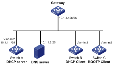
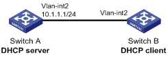
Network requirements
As shown in Figure 15, Switch A (DHCP server) assigns a static IP address, DNS server address, and gateway address to Switch B (DHCP client) and Switch C (BOOTP client) respectively.
The client ID of VLAN-interface 2 on Switch B is 3030-3066-2e65-3234-392e-3830-3530-2d56-6c61-6e2d-696e-7465-7266-6163-6532. The MAC address of VLAN-interface 2 on Switch C is 000f-e249-8050.
Configuration procedure
1. Configure the IP address of VLAN-interface 2 on Switch A:
<SwitchA> system-view
[SwitchA] interface vlan-interface 2
[SwitchA-Vlan-interface2] ip address 10.1.1.1 25
[SwitchA-Vlan-interface2] quit
2. Configure the DHCP server:
# Enable DHCP.
[SwitchA] dhcp enable
# Enable the DHCP server on VLAN-interface 2.
[SwitchA] interface vlan-interface 2
[SwitchA-Vlan-interface2] dhcp select server global-pool
[SwitchA-Vlan-interface2] quit
# Create DHCP address pool 0, configure a static binding, DNS server and gateway in it.
[SwitchA] dhcp server ip-pool 0
[SwitchA-dhcp-pool-0] static-bind ip-address 10.1.1.5 25
[SwitchA-dhcp-pool-0] static-bind client-identifier 3030-3066-2e65-3234-392e-3830-3530-2d56-6c61-6e2d-696e-7465-7266-6163-6532
[SwitchA-dhcp-pool-0] dns-list 10.1.1.2
[SwitchA-dhcp-pool-0] gateway-list 10.1.1.126
[SwitchA-dhcp-pool-0] quit
# Create DHCP address pool 1, configure a static binding, DNS server and gateway in it.
[SwitchA] dhcp server ip-pool 1
[SwitchA-dhcp-pool-1] static-bind ip-address 10.1.1.6 25
[SwitchA-dhcp-pool-1] static-bind mac-address 000f-e249-8050
[SwitchA-dhcp-pool-1] dns-list 10.1.1.2
[SwitchA-dhcp-pool-1] gateway-list 10.1.1.126
3. Verify the configuration.
After the preceding configuration is completed, Switch B can obtain IP address 10.1.1.5 and other network parameters, and Switch C can obtain IP address 10.1.1.6 and other network parameters from Switch A. You can use the display dhcp server ip-in-use command on the DHCP server to view the IP addresses assigned to the clients.
Dynamic IP address assignment configuration example
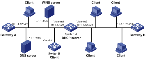
Network requirements
As shown in Figure 16, the DHCP server (Switch A) assigns IP address to clients in subnet 10.1.1.0/24, which is subnetted into 10.1.1.0/25 and 10.1.1.128/25. The IP addresses of VLAN-interfaces 1 and 2 on Switch A are 10.1.1.1/25 and 10.1.1.129/25 respectively. In address pool 10.1.1.0/25, the address lease duration is ten days and twelve hours, domain name suffix aabbcc.com, DNS server address 10.1.1.2/25, gateway 10.1.1.126/25, and WINS server 10.1.1.4/25. In address pool 10.1.1.128/25, the address lease duration is five days, domain name suffix aabbcc.com, DNS server address 10.1.1.2/25, and gateway address 10.1.1.254/25, and there is no WINS server address. The domain name and DNS server address on subnets 10.1.1.0/25 and 10.1.1.128/25 are the same. Therefore, the domain name suffix and DNS server address can be configured only for subnet 10.1.1.0/24. Subnet 10.1.1.128/25 can inherit the configuration of subnet 10.1.1.0/24.
Figure 16 Network diagram
Configuration procedure
1. Specify IP addresses for VLAN interfaces. (Details not shown)
2. Configure the DHCP server:
# Enable DHCP.
<SwitchA> system-view
[SwitchA] dhcp enable
# Enable the DHCP server on VLAN-interface 1 and VLAN-interface 2.
[SwitchA] interface vlan-interface 1
[SwitchA-Vlan-interface1] dhcp select server global-pool
[SwitchA-Vlan-interface1] quit
[SwitchA] interface vlan-interface 2
[SwitchA-Vlan-interface2] dhcp select server global-pool
[SwitchA-Vlan-interface2] quit
# Exclude IP addresses (addresses of the DNS server, WINS server and gateways).
[SwitchA] dhcp server forbidden-ip 10.1.1.2
[SwitchA] dhcp server forbidden-ip 10.1.1.4
[SwitchA] dhcp server forbidden-ip 10.1.1.126
[SwitchA] dhcp server forbidden-ip 10.1.1.254
# Configure DHCP address pool 0 (network segment, client domain name suffix, and DNS server address).
[SwitchA] dhcp server ip-pool 0
[SwitchA-dhcp-pool-0] network 10.1.1.0 mask 255.255.255.0
[SwitchA-dhcp-pool-0] domain-name aabbcc.com
[SwitchA-dhcp-pool-0] dns-list 10.1.1.2
[SwitchA-dhcp-pool-0] quit
# Configure DHCP address pool 1 (network segment, gateway, lease duration, and WINS server).
[SwitchA] dhcp server ip-pool 1
[SwitchA-dhcp-pool-1] network 10.1.1.0 mask 255.255.255.128
[SwitchA-dhcp-pool-1] gateway-list 10.1.1.126
[SwitchA-dhcp-pool-1] expired day 10 hour 12
[SwitchA-dhcp-pool-1] nbns-list 10.1.1.4
[SwitchA-dhcp-pool-1] quit
# Configure DHCP address pool 2 (network segment, gateway, and lease duration).
[SwitchA] dhcp server ip-pool 2
[SwitchA-dhcp-pool-2] network 10.1.1.128 mask 255.255.255.128
[SwitchA-dhcp-pool-2] expired day 5
[SwitchA-dhcp-pool-2] gateway-list 10.1.1.254
3. Verify the configuration.
After the preceding configuration is complete, clients on networks 10.1.1.0/25 and 10.1.1.128/25 can obtain IP addresses on the corresponding network and other network parameters from Switch A. You can use the display dhcp server ip-in-use command on the DHCP server to view the IP addresses assigned to the clients.
Self-defined option configuration example
Network requirements
As shown in Figure 17, the DHCP client (Switch B) obtains an IP address and PXE server addresses from the DHCP server (Switch A). The IP address that Switch B obtains belongs to subnet 10.1.1.0/24. The PXE server addresses are 1.2.3.4 and 2.2.2.2.
The DHCP server assigns PXE server addresses to DHCP clients through Option 43, a self-defined option. The format of Option 43 and that of the PXE server address list are shown in Figure 5 and Figure 7, respectively. The value of Option 43 configured on the DHCP server in this example is 80 0B 00 00 02 01 02 03 04 02 02 02 02. The number 80 is the value of the sub-option type. The number 0B is the value of the sub-option length. The numbers 00 00 are the value of the PXE server type. The number 02 indicates the number of servers. The numbers 01 02 03 04 02 02 02 02 indicate that the PXE server addresses are 1.2.3.4 and 2.2.2.2.
Configuration procedure
1. Specify IP addresses for the interfaces. (Details not shown)
2. Configure the DHCP server:
# Enable DHCP.
<SwitchA> system-view
[SwitchA] dhcp enable
# Enable the DHCP server on VLAN-interface 2.
[SwitchA] interface vlan-interface 2
[SwitchA-Vlan-interface2] dhcp select server global-pool
[SwitchA-Vlan-interface2] quit
# Configure DHCP address pool 0.
[SwitchA] dhcp server ip-pool 0
[SwitchA-dhcp-pool-0] network 10.1.1.0 mask 255.255.255.0
[SwitchA-dhcp-pool-0] option 43 hex 80 0B 00 00 02 01 02 03 04 02 02 02 02
3. Verify the configuration.
After the preceding configuration is complete, Switch B can obtain its IP address on 10.1.1.0/24 and PXE server addresses from the Switch A. You can use the display dhcp server ip-in-use command on the DHCP server to view the IP addresses assigned to the clients.
Troubleshooting DHCP server configuration
Symptom
A client’s IP address obtained from the DHCP server conflicts with another IP address.
Analysis
A host on the subnet may have the same IP address.
Solution
1. Disable the client’s network adapter or disconnect the client’s network cable. Ping the IP address of the client from another host to check whether there is a host using the same IP address.
2. If a ping response is received, the IP address has been manually configured on a host. Execute the dhcp server forbidden-ip command on the DHCP server to exclude the IP address from dynamic allocation.
3. Enable the network adapter or connect the network cable. Release the IP address and obtain another one on the client. Take WINDOW XP as an example, run cmd to enter DOS window. Type ipconfig/release to relinquish the IP address and then ipconfig/renew to obtain another IP address.
|
|
NOTE: The DHCP relay agent configuration is supported only on Layer 3 Ethernet interfaces (or subinterfaces), VLAN interfaces, and Layer 3 aggregate interfaces. |
Introduction to DHCP relay agent
Application environment
Via a relay agent, DHCP clients can communicate with a DHCP server on another subnet to obtain configuration parameters. Thus, DHCP clients on different subnets can contact the same DHCP server rather than having a DHCP server on each subnet.
|
|
NOTE: An MCE switch serving as the DHCP relay agent can forward DHCP packets not only between a DHCP server and clients on a public network, but also between a DHCP server and clients on a private network. Note that the IP address ranges of the public and private networks or those of private networks cannot overlap each other. For more information about MCE, see MPLS Configuration Guide. |
Fundamentals
Figure 18 shows a typical application of the DHCP relay agent.
Figure 18 DHCP relay agent application
The DHCP server and client interact with each other in a similar way with or without a relay agent. (see the chapter “DHCP overview”).
Figure 19 DHCP relay agent work process
1. After receiving a DHCP-DISCOVER or DHCP-REQUEST broadcast message from a DHCP client, the DHCP relay agent fills the giaddr field of the message with its IP address and forwards the message to the designated DHCP server in unicast mode.
2. Based on the giaddr field, the DHCP server returns an IP address and other configuration parameters to the relay agent, and the relay agent conveys them to the client.
DHCP relay agent support for Option 82
Option 82 records the location information of the DHCP client, letting the administrator locate the DHCP client for security control and accounting purposes. For more information, see the chapter “DHCP overview.”
If the DHCP relay agent supports Option 82, it handles a client’s request according to the contents defined in Option 82, if any. The handling strategies are described in Table 2.
If a reply returned by the DHCP server contains Option 82, the DHCP relay agent removes the Option 82 before forwarding the reply to the client.
Table 2 Handling strategies of the DHCP relay agent
|
If a client’s requesting message has… |
Handling strategy |
Padding format |
The DHCP relay agent will… |
|
Option 82 |
Drop |
Random |
Drop the message. |
|
Keep |
Random |
Forward the message without changing Option 82. |
|
|
Replace |
normal |
Forward the message after replacing the original Option 82 with the Option 82 padded in normal format. |
|
|
verbose |
Forward the message after replacing the original Option 82 with the Option 82 padded in verbose format. |
||
|
user-defined |
Forward the message after replacing the original Option 82 with the user-defined Option 82. |
||
|
no Option 82 |
N/A |
normal |
Forward the message after adding the Option 82 padded in normal format. |
|
N/A |
verbose |
Forward the message after adding the Option 82 padded in verbose format. |
|
|
N/A |
user-defined |
Forward the message after adding the user-defined Option 82. |
DHCP relay agent configuration task list
Complete the following tasks to configure the DHCP relay agent:
|
Task |
Remarks |
|
Required |
|
|
Required |
|
|
Correlating a DHCP server group with a relay agent interface. |
Required |
|
Optional |
|
|
Optional |
|
|
Optional |
|
|
Optional |
|
|
Optional |
Enabling DHCP
Enable DHCP before performing other DHCP-related configurations.
To enable DHCP:
|
Step |
Command |
Remarks |
|
1. Enter system view. |
system-view |
N/A |
|
2. Enable DHCP. |
dhcp enable |
Disabled by default |
Enabling the DHCP relay agent on an interface
With the DHCP relay agent enabled, an interface forwards incoming DHCP requests to a DHCP server for address allocation.
To enable the DHCP relay agent on an interface:
|
Step |
Command |
Remarks |
|
1. Enter system view. |
system-view |
N/A |
|
2. Enter interface view. |
interface interface-type interface-number |
N/A |
|
3. Enable the DHCP relay agent on the current interface. |
dhcp select relay |
With DHCP enabled, interfaces work in the DHCP server mode. |
|
|
NOTE: If the DHCP client obtains an IP address via the DHCP relay agent, the address pool of the subnet to which the IP address of the DHCP relay agent ‘s interface connecting the DHCP client belongs must be configured on the DHCP server. Otherwise, the DHCP client cannot obtain a correct IP address. |
Correlating a DHCP server group with a relay agent interface
To improve reliability, you can specify several DHCP servers as a group on the DHCP relay agent and correlate a relay agent interface with the server group. When the interface receives request messages from clients, the relay agent will forward them to all the DHCP servers of the group.
Configuration guidelines
When you correlate a DHCP server group with a relay agent interface, follow these guidelines:
· You can specify up to 20 DHCP server groups on the relay agent and eight DHCP server addresses for each DHCP server group.
· By executing the dhcp relay server-group command repeatedly, you can specify up to eight DHCP server addresses for each DHCP server group.
· The IP addresses of DHCP servers and those of relay agent’s interfaces that connect DHCP clients cannot be on the same subnet. Otherwise, the client cannot obtain an IP address.
· The IP addresses of DHCP servers and those of relay agent’s interfaces cannot be on the same subnet. Otherwise, the client cannot obtain an IP address.
· A DHCP server group can correlate with one or multiple DHCP relay agent interfaces, but a relay agent interface can only correlate with one DHCP server group. Using the dhcp relay server-select command repeatedly overwrites the previous configuration. However, if the specified DHCP server group does not exist, the interface still uses the previous correlation.
· The group-id in the dhcp relay server-select command was specified by the dhcp relay server-group command.
Configuration procedure
To correlate a DHCP server group with a relay agent interface:
|
Step |
Command |
Remarks |
|
1. Enter system view. |
system-view |
N/A |
|
2. Create a DHCP server group and add a server into the group. |
dhcp relay server-group group-id ip ip-address |
Not created by default. |
|
3. Enter interface view. |
interface interface-type interface-number |
N/A |
|
4. Correlate the DHCP server group with the current interface. |
dhcp relay server-select group-id |
By default, no interface is correlated with any DHCP server group. |
Configuring the DHCP relay agent security functions
Configuring address check
Address check can block illegal hosts from access external networks.
With this feature enabled, the DHCP relay agent can dynamically record clients’ IP-to-MAC bindings after the clients obtain IP addresses through DHCP. You can configure static IP-to-MAC bindings on the DHCP relay agent so that users can access external networks using fixed IP addresses.
Upon receiving an ARP packet, the DHCP relay agent checks the sender’s IP and MAC addresses in the packet against the recorded dynamic and static bindings. If no match is found, the DHCP relay agent does not learn the ARP entry and prohibits the requesting client from accessing external networks via the DHCP relay agent.
Configuration guidelines
When you configure the address check, follow these guidelines:
· The dhcp relay address-check enable command can be executed only on Layer 3 Ethernet interfaces (including sub-interfaces) and VLAN interfaces.
· Before enabling address check on an interface, you must enable the DHCP service, and enable the DHCP relay agent on the interface; otherwise, the address check configuration is ineffective.
· The dhcp relay address-check enable command only checks IP and MAC addresses of clients.
· When using the dhcp relay security static command to bind an interface to a static binding entry, make sure that the interface is configured as a DHCP relay agent; otherwise, address entry conflicts may occur.
· When a synchronous/asynchronous serial interface requests an IP address through DHCP, the DHCP relay agent does not record the corresponding IP-to-MAC binding.
Configuration procefure
To create a static binding and enable address check:
|
Step |
Command |
Remarks |
|
1. Enter system view. |
system-view |
N/A |
|
2. Create a static binding. |
dhcp relay security static ip-address mac-address [ interface interface-type interface-number ] |
Optional. No static binding is created by default. |
|
3. Enter interface view. |
interface interface-type interface-number |
N/A |
|
4. Configure address check. |
dhcp relay address-check enable |
Disabled by default. |
Configuring periodic refresh of dynamic client entries
A DHCP client unicasts a DHCP-RELEASE message to the DHCP server when releasing its dynamically obtained IP address. The DHCP relay agent simply conveys the message to the DHCP server and does not remove the IP-to-MAC binding. To solve this problem, the periodic refresh of dynamic client entries feature is introduced.
With this feature, the DHCP relay agent uses the IP address of a client and the MAC address of the DHCP relay interface to periodically send a DHCP-REQUEST message to the DHCP server.
· If the server returns a DHCP-ACK message or does not return any message within a specified interval, the DHCP relay agent ages out the client entry.
· If the server returns a DHCP-NAK message, the relay agent keeps the client entry.
To configure dynamic binding update interval:
|
Step |
Command |
Remarks |
|
1. Enter system view. |
system-view |
N/A |
|
2. Enable periodic refresh of dynamic client entries. |
dhcp relay security refresh enable |
Optional. Enabled by default. |
|
3. Configure binding update interval. |
dhcp relay security tracker { interval | auto } |
Optional. auto by default. (auto interval is calculated by the relay agent according to the number of bindings.) |
Configuring the DHCP relay agent to support authorized ARP
A DHCP relay agent can work in cooperation with authorized ARP to block illegal clients.
With this feature enabled, when a client obtains an IP address from the DHCP server through a DHCP relay agent, the DHCP relay agent can automatically record the client’s IP-to-MAC binding and use this client entry to update the corresponding ARP entry.
When authorized ARP is enabled on the DHCP relay agent, the ARP automatic learning function is disabled. Then dynamic client entries are used to update ARP entries and avoid learning incorrect ARP entries.
This feature makes sure that:
· The clients that obtain IP addresses through DHCP have ARP entries on the DHCP relay agent, and can access the network.
· The clients that do not obtain IP addresses through DHCP have no ARP entries on the DHCP relay agent, and are considered illegal clients and unable to access the network.
Configuration guidelines
When you configure the DHCP relay agent to support authorized ARP, follow these guidelines:
· Authorized ARP can only be configured on Layer 3 Ethernet interfaces.
· Disabling the DHCP relay agent to support authorized ARP will delete the corresponding authorized ARP entries.
· The DHCP relay agent does not notify the authorized ARP module of the static bindings. You must configure the corresponding static ARP entries for authorized ARP.
· For more information about authorized ARP, see Security Configuration Guide. For more information about the arp authorized enable command, see Security Command Reference.
Configuration procedure
To configure the DHCP relay agent to support authorized ARP:
|
Step |
Command |
Remarks |
|
1. Enter system view. |
system-view |
N/A |
|
2. Enter interface view. |
interface interface-type interface-number |
N/A |
|
3. Configure the DHCP relay agent to support authorized ARP. |
dhcp update arp |
Not supported by default |
|
4. Enable authorized ARP. |
arp authorized enable |
Not enabled by default |
Enabling unauthorized DHCP server detection
Unauthorized DHCP servers may assign wrong IP addresses to DHCP clients.
With unauthorized DHCP servers detection enabled, the DHCP relay agent checks whether a request contains Option 54 (Server Identifier Option). If yes, the DHCP relay agent records the IP address in the option, which is the IP address of the DHCP server that assigned an IP address to the DHCP client, and records the receiving interface. The administrator can use this information to check for unauthorized DHCP servers.
To enable unauthorized DHCP server detection:
|
Step |
Command |
Remarks |
|
1. Enter system view. |
system-view |
N/A |
|
2. Enable unauthorized DHCP server detection. |
dhcp relay server-detect |
Disabled by default |
|
|
NOTE: With unauthorized DHCP server detection enabled, the switch puts a record only once for each DHCP server. The administrator needs to find unauthorized DHCP servers based on the log information. |
Enabling DHCP starvation attack protection
A DHCP starvation attack occurs when an attacker constantly sends forged DHCP requests using different MAC addresses in the chaddr field to a DHCP server. This exhausts the IP address resources of the DHCP server so that legitimate DHCP clients cannot obtain IP addresses. The DHCP server may also fail to work because of exhaustion of system resources.
· To relieve a DHCP starvation attack that uses DHCP packets encapsulated with different source MAC addresses, you can limit the number of ARP entries that a Layer 3 interface can learn or MAC addresses that a Layer 2 port can learn. You can also configure an interface that has learned the maximum MAC addresses to discard packets whose source MAC addresses are not in the MAC address table.
· To prevent a DHCP starvation attack that uses DHCP requests encapsulated with the same source MAC address, enable MAC address check on the DHCP relay agent. With this function enabled, the DHCP relay agent compares the chaddr field of a received DHCP request with the source MAC address field of the frame. If they are the same, the DHCP relay agent decides this request as valid and forwards it to the DHCP server; if not, the DHCP request is discarded.
To enable MAC address check:
|
Step |
Command |
Remarks |
|
1. Enter system view. |
system-view |
N/A |
|
2. Enter interface view. |
interface interface-type interface-number |
N/A |
|
3. Enable MAC address check. |
dhcp relay check mac-address |
Disabled by default |
|
|
NOTE: DHCP relay agents change the source MAC addresses when forwarding DHCP packets. Therefore, you can enable MAC address check only on a DHCP relay agent directly connected to DHCP clients. Otherwise, valid DHCP packets may be discarded and clients cannot obtain IP addresses. |
Enabling client offline detection
With this feature enabled, the DHCP relay agent considers a DHCP client goes offline when the ARP entry for the client ages out. In addition, it removes the client entry and sends a DHCP-RELEASE message to the DHCP server to release the IP address of the client.
To enable offline detection:
|
Step |
Command |
Remarks |
|
1. Enter system view. |
system-view |
N/A |
|
2. Enter interface view. |
interface interface-type interface-number |
N/A |
|
3. Enable offline detection. |
dhcp relay client-detect enable |
Disabled by default |
|
|
NOTE: Removing an ARP entry manually does not remove the corresponding client’s IP-to-MAC binding. When the client goes offline, use the undo dhcp relay security command to remove the IP-to-MAC binding manually. |
Configuring the DHCP relay agent to release an IP address
You can configure the relay agent to release a client’s IP address. The relay agent sends a DHCP-RELEASE message that contains the specified IP address. Upon receiving the DHCP-RELEASE message, the DHCP server releases the IP address; meanwhile, the client entry is removed from the DHCP relay agent.
To configure the DHCP relay agent in system view to send DHCP-RELEASE messages:
|
Step |
Command |
|
1. Enter system view. |
system-view |
|
2. Configure the DHCP relay agent to release an IP address. |
dhcp relay release ip client-ip |
|
|
NOTE: · The IP address to be released must be available in a dynamic client entry. · Dynamic client entries can be generated only after you enable address check, authorized ARP, or IP source guard on the DHCP relay agent. For more information about IP source guard, see Security Configuration Guide. |
Configuring the DHCP relay agent to support Option 82
Configuration prerequisites
You need to complete the following tasks before configuring the DHCP relay agent to support Option 82.
· Enabling DHCP
· Enabling the DHCP relay agent on the specified interface
· Correlating a DHCP server group with relay agent interfaces
Configuration procedure
To configure the DHCP relay agent to support Option 82:
|
Step |
Command |
Remarks |
|
1. Enter system view. |
system-view |
N/A |
|
2. Enter interface view. |
interface interface-type interface-number |
N/A |
|
3. Enable the relay agent to support Option 82. |
dhcp relay information enable |
Disabled by default. |
|
4. Configure the handling strategy for requesting messages containing Option 82. |
dhcp relay information strategy { drop | keep | replace } |
Optional. replace by default. |
|
5. Configure non-user-defined Option 82. |
· Configure the padding format for Option 82: · Configure the code type for the circuit ID sub-option: ·
Configure the code type for the remote ID
sub-option: |
Optional. By default, · The padding format for Option 82is normal. · The code type for the circuit ID sub-option depends on the padding format of Option 82. Each field has its own code type. · The code type for the remote ID sub-option is hex. The code type configuration for the circuit ID sub-option and for the remote ID sub-option apply to non-user-defined Option 82 only. |
|
6. Configure user-defined Option 82. |
· Configure the padding content for the circuit ID sub-option: ·
Configure the padding content for the remote
ID sub-option: |
Optional. By default, the padding content depends on the padding format of Option 82. |
|
|
NOTE: · To support Option 82, perform related configuration on both the DHCP server and relay agent. For DHCP server configuration of this kind, see the chapter “DHCP server configuration.” · If the handling strategy of the DHCP relay agent is configured as replace, you need to configure a padding format for Option 82. If the handling strategy is keep or drop, you need not configure any padding format. · If sub-option 1 (node identifier) of Option 82 contains the device name (sysname) of a node, the device name must contain no spaces. Otherwise, the DHCP relay agent will drop the message. |
Displaying and maintaining the DHCP relay agent
|
Task |
Command |
Remarks |
|
Display information about DHCP server groups correlated to a specified or all interfaces. |
display dhcp relay { all | interface interface-type interface-number } [ | { begin | exclude | include } regular-expression ] |
Available in any view |
|
Display Option 82 configuration information on the DHCP relay agent. |
display dhcp relay information { all | interface interface-type interface-number } [ | { begin | exclude | include } regular-expression ] |
Available in any view |
|
Display information about bindings of DHCP relay agents. |
display dhcp relay security [ ip-address | dynamic | static ] [ | { begin | exclude | include } regular-expression ] |
Available in any view |
|
Display statistics information about bindings of DHCP relay agents. |
display dhcp relay security statistics [ | { begin | exclude | include } regular-expression ] |
Available in any view |
|
Display information about the refreshing interval for entries of dynamic IP-to-MAC bindings. |
display dhcp relay security tracker [ | { begin | exclude | include } regular-expression ] |
Available in any view |
|
Display information about the configuration of a specified or all DHCP server groups. |
display dhcp relay server-group { group-id | all } [ | { begin | exclude | include } regular-expression ] |
Available in any view |
|
Display packet statistics on relay agent. |
display dhcp relay statistics [ server-group { group-id | all } ] [ | { begin | exclude | include } regular-expression ] |
Available in any view |
|
Clear packet statistics from relay agent. |
reset dhcp relay statistics [ server-group group-id ] |
Available in user view |
DHCP relay agent configuration examples
DHCP relay agent configuration example
Network requirements
As shown in Figure 20, DHCP clients reside on network 10.10.1.0/24. The IP address of the DHCP server is 10.1.1.1/24. Because the DHCP clients reside on a different network with the DHCP server, a DHCP relay agent is deployed to forward messages between DHCP clients and the DHCP server.
VLAN-interface 1 of the DHCP relay agent (Switch A) connects to the subnet where DHCP clients reside. The IP address of VLAN-interface 1 is 10.10.1.1/24, and the IP address of VLAN-interface 2 is 10.1.1.2/24.
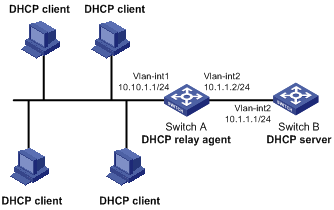
Configuration procedure
# Specify IP addresses for the interfaces. (Details not shown)
# Enable DHCP.
<SwitchA> system-view
[SwitchA] dhcp enable
# Add DHCP server 10.1.1.1 into DHCP server group 1.
[SwitchA] dhcp relay server-group 1 ip 10.1.1.1
# Enable the DHCP relay agent on VLAN-interface 1.
[SwitchA] interface vlan-interface 1
[SwitchA-Vlan-interface1] dhcp select relay
# Correlate VLAN-interface 1 to DHCP server group 1.
[SwitchA-Vlan-interface1] dhcp relay server-select 1
After the preceding configuration is complete, DHCP clients can obtain IP addresses and other network parameters through the DHCP relay agent from the DHCP server. You can use the display dhcp relay statistics command to view statistics of DHCP packets forwarded by DHCP relay agents. After you enable address check of the DHCP relay agents with the dhcp relay address-check enable command, use the display dhcp relay security command to view bindings of DHCP relay agents.
|
|
NOTE: · Because the DHCP relay agent and server are on different subnets, you must configure a static route or dynamic routing protocol to make them reachable to each other. · Configurations on the DHCP server are also required to guarantee the client-server communication via the DHCP relay agent. For DHCP server configuration information, see the chapter “DHCP server configuration.” |
DHCP relay agent Option 82 support configuration example
Network requirements
As shown in Figure 20, Option 82 is enabled on the DHCP relay agent (Switch A). The handling strategy for DHCP requests containing Option 82 is configured as replace. The padding content for the circuit ID sub-option is configured as company001 and for the remote ID sub-option as device001.
Switch A forwards DHCP requests to the DHCP server (Switch B) after replacing Option 82 in the requests, so that the DHCP clients can obtain IP addresses.
Configuration procedure
# Specify IP addresses for the interfaces. (Details not shown)
# Enable DHCP.
<SwitchA> system-view
[SwitchA] dhcp enable
# Add DHCP server 10.1.1.1 into DHCP server group 1.
[SwitchA] dhcp relay server-group 1 ip 10.1.1.1
# Enable the DHCP relay agent on VLAN-interface 1.
[SwitchA] interface vlan-interface 1
[SwitchA-Vlan-interface1] dhcp select relay
# Correlate VLAN-interface 1 to DHCP server group 1.
[SwitchA-Vlan-interface1] dhcp relay server-select 1
# Enable the DHCP relay agent to support Option 82, and perform Option 82-related configurations.
[SwitchA-Vlan-interface1] dhcp relay information enable
[SwitchA-Vlan-interface1] dhcp relay information strategy replace
[SwitchA-Vlan-interface1] dhcp relay information circuit-id string company001
[SwitchA-Vlan-interface1] dhcp relay information remote-id string device001
|
|
NOTE: Configurations on the DHCP server are also required to make the Option 82 configurations function normally. |
Troubleshooting DHCP relay agent configuration
Symptom
DHCP clients cannot obtain any configuration parameters via the DHCP relay agent.
Analysis
Some problems may occur with the DHCP relay agent or server configuration.
Solution
To locate the problem, enable debugging and execute the display command on the DHCP relay agent to view the debugging information and interface state information.
Check that:
· The DHCP is enabled on the DHCP server and relay agent.
· The address pool on the same subnet where DHCP clients reside is available on the DHCP server.
· The routes between the DHCP server and DHCP relay agent are reachable.
· The relay agent interface connected to DHCP clients is correlated with correct DHCP server group and IP addresses for the group members are correct.
Configuring DHCP client
|
|
NOTE: · The DHCP client configuration is supported only on Layer 3 Ethernet interfaces (or subinterfaces), VLAN interfaces, and Layer 3 aggregate interfaces. · An interface in an aggregation group cannot be enabled with the DHCP client. · To enable multiple VLAN interfaces with the same MAC address to use the DHCP client to get IP addresses via a relay agent, the DHCP server must not run on Windows Server 2000 or Windows Server 2003. |
An interface enabled with the DHCP client uses DHCP to obtain configuration parameters such as an IP address from the DHCP server.
Enabling the DHCP client on an interface
To enable the DHCP client on an interface:
|
Step |
Command |
Remarks |
|
1. Enter system view. |
system-view |
N/A |
|
2. Enter interface view. |
interface interface-type interface-number |
N/A |
|
3. Enable the DHCP client on the interface. |
ip address dhcp-alloc [ client-identifier mac interface-type interface-number ] |
Disabled by default |
|
|
NOTE: · If the DHCP client enabled on an interface fails to get an IP address multiple times, the DHCP client stops address acquisition. · An interface supports multiple address acquisition methods. A newly configured address acquisition method overwrites the previous one. · Secondary IP addresses cannot be configured on an interface that is enabled with the DHCP client. · If the IP address that interface A obtains from the DHCP server is on the same network segment as the IP address of interface B, interface A does not use the IP address or request another IP address from the DHCP server, unless the IP address of interface B is manually deleted and interface A is brought up again by first executing the shutdown command and then the undo shutdown command or the DHCP client is re-enabled on interface A by executing the undo ip address dhcp-alloc command and then the ip address dhcp-alloc command. |
Displaying and maintaining the DHCP client
|
Task |
Command |
Remarks |
|
Display DHCP client information. |
display dhcp client [ verbose ] [ interface interface-type interface-number ] [ | { begin | exclude | include } regular-expression ] |
Available in any view |
DHCP client configuration example
Network requirements
As shown in Figure 22, Switch B contacts the DHCP server via VLAN-interface 2 to obtain the following configuration information:
· IP addresses of DHCP clients on network 10.1.1.0/24
· DNS server address 20.1.1.1/24
· ACS address 10.153.114.21/24
· Static route destined for network 20.1.1.0/24 through next hop 10.1.1.2
The DHCP server uses Option 121 to assign static route information to DHCP clients. Figure 21 shows the format of Option 121. The destination descriptor field comprises two parts, subnet mask length and destination network address. In this example, the value of the destination descriptor field takes 18 14 01 01, a hexadecimal number indicating that the subnet mask length is 24 and destination network address is 20.1.1.0, and the value of the next hop address field takes 0A 01 01 02, a hexadecimal number indicating that the next hop is 10.1.1.2.
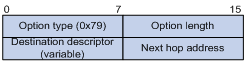
The DHCP server uses Option 43 to assign ACS information to the clients. The ACS can update configuration files for the clients and reboot and monitor the clients. The format of Option 43 is shown in Figure 5, and the format of ACS parameter suboption is shown in Figure 6.
This example uses the ACS address http://10.153.114.21:9090 (the hexadecimal value of the corresponding ASCII code is 01266874 74703A2F 2F31302E 3135332E 3131342E 32313A39 30393020), and the default CPE authentication. The user name is bims (the hexadecimal value of the corresponding ASCII code is 62696D73), the password is imcbims (the hexadecimal value of the corresponding ASCII code is 696D63 62696D73). The hexadecimal value of the ASCII code for space is 20.
The complete Option 43 representation for http:// 10.153.114.21:9090:9090 bims imcbims is:
option 43 hex 01246874 74703A2F 2F313932 2E313638 2E312E32 3A393039 30206269 6D732069 6D636269 6D73.
Figure 22 Network diagram
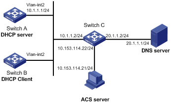
Configuration procedure
1. Configure Switch A:
# Configure the IP address of VLAN-interface 2.
<SwitchA> system-view
[SwitchA] interface vlan-interface 2
[SwitchA-Vlan-interface2] ip address 10.1.1.1 24
[SwitchA-Vlan-interface2] quit
# Enable the DHCP service.
[SwitchA] dhcp enable
# Exclude an IP address from automatic allocation.
[SwitchA] dhcp server forbidden-ip 10.1.1.2
# Configure DHCP address pool 0 and specify the subnet, lease duration, DNS server address, and a static route to subnet 20.1.1.0/24. The ACS address is http://10.153.114.21:9090.
[SwitchA] dhcp server ip-pool 0
[SwitchA-dhcp-pool-0] network 10.1.1.0 mask 255.255.255.0
[SwitchA-dhcp-pool-0] expired day 10
[SwitchA-dhcp-pool-0] dns-list 20.1.1.1
[SwitchA-dhcp-pool-0] option 121 hex 18 14 01 01 0A 01 01 02
[SwitchA-dhcp-pool-0] option 43 hex 01266874 74703A2F 2F31302E 3135332E 3131342E 32313A39 30393020 62596D73 20696D63 62696D73
2. Configure Switch B:
# Enable the DHCP client on VLAN-interface 2.
<SwitchB> system-view
[SwitchB] interface vlan-interface 2
[SwitchB-Vlan-interface2] ip address dhcp-alloc
3. Verify the configuration.
# Use the display dhcp client command to view the IP address and other network parameters assigned to Switch B.
[SwitchB-Vlan-interface2] display dhcp client verbose
Vlan-interface2 DHCP client information:
Current machine state: BOUND
Allocated IP: 10.1.1.3 255.255.255.0
Allocated lease: 864000 seconds, T1: 432000 seconds, T2: 756000 seconds
Lease from 2009.02.20 11:06:35 to 2009.03.02 11:06:35
DHCP server: 10.1.1.1
Transaction ID: 0x410090f0
Classless static route:
Destination: 20.1.1.0, Mask: 255.255.255.0, NextHop: 10.1.1.2
DNS server: 20.1.1.1
Client ID: 3030-3066-2e65-3230-
302e-3030-3032-2d45-
7468-6572-6e65-7430-
2f30
T1 will timeout in 4 days 23 hours 59 minutes 50 seconds.
# Use the display ip routing-table command to view the route information on Switch B. A static route to network 20.1.1.0/24 is available in the routing table.
[SwitchB-Vlan-interface2] display ip routing-table
Routing Tables: Public
Destinations : 5 Routes : 5
Destination/Mask Proto Pre Cost NextHop Interface
10.1.1.0/24 Direct 0 0 10.1.1.3 Vlan2
10.1.1.3/32 Direct 0 0 127.0.0.1 InLoop0
20.1.1.0/24 Static 70 0 10.1.1.2 Vlan2
127.0.0.0/8 Direct 0 0 127.0.0.1 InLoop0
127.0.0.1/32 Direct 0 0 127.0.0.1 InLoop0
# Use the display cwmp configuration command to view the CWMP configuration on Switch B.
[SwitchB-Vlan-interface2] display cwmp configuration
TR-069 is enabled.
ACS URL :http://10.153.114.21:9090
ACS username :bims
ACS password :imcbims
Inform enable status :disabled
Inform interval :600s
Inform time :none
Wait timeout :30s
Reconnection times :Unlimited
Source IP interface :none
|
|
NOTE: For more information about the command display cwmp configuration, see Network Management and Monitoring Command Reference. |
DHCP snooping overview
DHCP snooping functions
DHCP snooping can:
1. Ensure DHCP clients to obtain IP addresses from authorized DHCP servers;
2. Record IP-to-MAC mappings of DHCP clients
Ensuring DHCP clients to obtain IP addresses from authorized DHCP servers
With DHCP snooping, the ports of a switch can be configured as trusted or untrusted to make sure that clients obtain IP address only from authorized DHCP servers.
· Trusted—A trusted port forwards DHCP messages normally.
· Untrusted—An untrusted port discards the DHCP-ACK or DHCP-OFFER messages from any DHCP server.
Configure ports that connect to authorized DHCP servers or other DHCP snooping devices as trusted, and configure other ports as untrusted.
Recording IP-to-MAC mappings of DHCP clients
DHCP snooping reads DHCP-REQUEST messages and DHCP-ACK messages from trusted ports to record DHCP snooping entries. A DHCP snooping entry includes the MAC and IP addresses of the client., the port that connects to the DHCP client, and the VLAN of the port. With DHCP snooping entries, DHCP snooping can implement the following functions:
· ARP detection—Whether ARP packets are sent from an authorized client is determined based on DHCP snooping entries. This feature prevents ARP attacks from unauthorized clients. For more information, see Security Configuration Guide.
· IP source guard—IP source guard uses dynamic binding entries generated by DHCP snooping to filter packets on a per-port basis, and prevents unauthorized packets from traveling through. For more information, see Security Configuration Guide.
Application environment of trusted ports
Configuring a trusted port connected to a DHCP server
Figure 23 Trusted port configuration
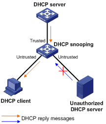
As shown in Figure 23, the trusted port forwards reply messages from the DHCP server to the client, but the untrusted port connected to the unauthorized DHCP server cannot forward any reply messages. This makes sure that the DHCP client can obtain an IP address from the authorized DHCP server.
Configuring trusted ports in a cascaded network
In a cascaded network involving multiple DHCP snooping devices, the ports connected to other DHCP snooping devices should be configured as trusted ports.
To save system resources, you can disable the trusted ports, which are not directly connected to DHCP clients, from recording clients’ IP-to-MAC bindings upon receiving DHCP requests.
Figure 24 Configuring trusted ports in a cascaded network
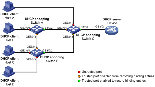
Table 3 describes roles of the ports shown in Figure 24.
|
Device |
Untrusted port |
Trusted port disabled from recording binding entries |
Trusted port enabled to record binding entries |
|
Switch A |
GigabitEthernet 3/0/1 |
GigabitEthernet 3/0/3 |
GigabitEthernet 3/0/2 |
|
Switch B |
GigabitEthernet 3/0/3 and GigabitEthernet 3/0/4 |
GigabitEthernet 3/0/1 |
GigabitEthernet 3/0/2 |
|
Switch C |
GigabitEthernet 3/0/1 |
GigabitEthernet 3/0/3 and GigabitEthernet 3/0/4 |
GigabitEthernet 3/0/2 |
DHCP snooping support for Option 82
Option 82 records the location information of the DHCP client. The administrator can locate the DHCP client for security control and accounting purposes. For more information, see the chapter “DHCP overview.”
If DHCP snooping supports Option 82, it will handle a client’s request according to the contents defined in Option 82, if any. The handling strategies are described in Table 4.
If a reply returned by the DHCP server contains Option 82, the DHCP snooping device will remove the Option 82 before forwarding the reply to the client. If the reply contains no Option 82, the DHCP snooping device forwards it directly.
Table 4 Handling strategies of DHCP snooping
|
If a client’s requesting message has… |
Handling strategy |
Padding format |
The DHCP snooping switch will… |
|
Option 82 |
Drop |
Random |
Drop the message. |
|
Keep |
Random |
Forward the message without changing Option 82. |
|
|
Replace |
normal |
Forward the message after replacing the original Option 82 with the Option 82 padded in normal format. |
|
|
verbose |
Forward the message after replacing the original Option 82 with the Option 82 padded in verbose format. |
||
|
user-defined |
Forward the message after replacing the original Option 82 with the user-defined Option 82. |
||
|
Append |
normal |
Forward the message without changing Option 82. |
|
|
verbose |
Forward the message without changing Option 82. |
||
|
private |
Forward the message after adding sub-option 9 to option 82 or adding content to sub-option 9 that option 82 contains. |
||
|
standard |
Forward the message without changing Option 82. |
||
|
user-defined |
Forward the message without changing Option 82. |
||
|
no Option 82 |
N/A |
normal |
Forward the message after adding the Option 82 padded in normal format. |
|
N/A |
private |
Forward the message after adding the Option 82 padded in private format. |
|
|
N/A |
standard |
Forward the message after adding the Option 82 padded in standard format. |
|
|
N/A |
verbose |
Forward the message after adding the Option 82 padded in verbose format. |
|
|
N/A |
user-defined |
Forward the message after adding the user-defined Option 82. |
|
|
NOTE: The handling strategy and padding format for Option 82 on the DHCP snooping device are the same as those on the relay agent. |
Configuring DHCP snooping basic functions
Configuration guidelines
When you configure DHCP snooping basic functions, follow these guidelines:
· You need to specify the ports connected to the valid DHCP servers as trusted to make sure that DHCP clients can obtain valid IP addresses. The trusted port and the port connected to the DHCP client must be in the same VLAN.
· You can specify Layer 2 Ethernet interfaces and Layer 2 aggregate interfaces as trusted ports. For more information about aggregate interfaces, see Layer 2—LAN Switching Configuration Guide.
· If an Ethernet interface is added to an aggregation group, DHCP snooping configured on the interface will not take effect. After the interface quits from the aggregation group, DHCP snooping will be effective.
· DHCP snooping can work with basic QinQ or flexible QinQ. When receiving a packet without any VLAN tag from the DHCP client to the DHCP server, the DHCP snooping device adds a VLAN tag to the packet. If the packet has one VLAN tag, the device adds another VLAN tag to the packet and records the two VLAN tags in a DHCP snooping entry. The newly added VLAN tag is the outer tag. If the packet has two VLAN tags, the device directly forwards the packet to the DHCP server without adding any tag. If you need to add a new VLAN tag and meanwhile modify the original VLAN tag for the packet, DHCP snooping cannot work with flexible QinQ.
Configuration procedure
To configure DHCP snooping basic functions:
|
Step |
Command |
Remarks |
|
1. Enter system view. |
system-view |
N/A |
|
2. Enable DHCP snooping. |
dhcp-snooping |
Disabled by default. |
|
3. Enter Ethernet interface view. |
interface interface-type interface-number |
The interface connects to the DHCP server. |
|
4. Specify the port as a trusted port that records the IP-to-MAC bindings of clients. |
dhcp-snooping trust |
After DHCP snooping is enabled, a port is an untrusted port by default. |
|
5. Return to system view. |
quit |
N/A |
|
6. Enter interface view. |
interface interface-type interface-number |
The interface indirectly connects to the DHCP client. |
|
7. Specify the port as a trusted port that does not record the IP-to-MAC bindings of clients. |
dhcp-snooping trust no-user-binding |
Optional. After DHCP snooping is enabled, a port is an untrusted port by default. |
Configuring DHCP snooping to support Option 82
Configuration guidelines
When you configure DHCP snooping to support Option 82, follow these guidelines:
· You can configure DHCP snooping to support Option 82 on Layer 2 Ethernet interfaces or Layer 2 aggregate interfaces only.
· If a Layer 2 Ethernet interface is added to an aggregation group, enabling DHCP snooping to support Option 82 on the interface will not take effect. After the interface quits the aggregation group, the configuration will be effective.
· To support Option 82, perform related configuration on both the DHCP server and the switch enabled with DHCP snooping. For DHCP server configuration of this kind, see the chapter “DHCP server configuration.”
· If the handling strategy of the DHCP-snooping-enabled switch is configured as replace, you need to configure a padding format for Option 82. If the handling strategy is keep or drop, you need not configure any padding format.
· If the Option 82 contains the device name (sysname) of a node, the device name must contain no spaces. Otherwise, the DHCP-snooping-enabled switch will drop the message. You can use the sysname command to specify the device name. For more information about this command, see Fundamentals Command Reference.
· If DHCP snooping and QinQ work together or the DHCP snooping device receives a DHCP packet with two VLAN tags, and the normal or verbose padding format is adopted for Option 82, DHCP snooping fills the VLAN ID field of sub-option 1 with outer VLAN tag.inter VLAN tag. For example, if the outer VLAN tag is 10 (a in hexadecimal) and the inner VLAN tag is 20 (14 in hexadecimal), the VLAN ID is 000a.0014.
Configuration procedure
To configure DHCP snooping to support Option 82:
|
Step |
Command |
Remarks |
|
1. Enter system view. |
system-view |
N/A |
|
2. Enter interface view. |
interface interface-type interface-number |
N/A |
|
3. Enable DHCP snooping to support Option 82. |
dhcp-snooping information enable |
Disabled by default. |
|
4. Configure the handling strategy for requesting messages containing Option 82. |
dhcp-snooping information strategy { append | drop | keep | replace } |
Optional. replace by default. |
|
5. Configure Option 82 in the non-user-defined. |
·
Configure the padding format for Option 82: · Configure the code type for the circuit ID sub-option: · Configure the code type for the remote ID sub-option: ·
Enable sub-option 9: |
Optional. By default, · The padding format for Option 82 is normal. · The code type for the circuit ID sub-option depends on the padding format of Option 82. Each field has its own code type. · The code type for the remote ID sub-option is hex. · Sub-option 9 is not enabled. The code type configuration for the circuit ID sub-option and the remote ID sub-option apply to non-user-defined Option 82 only. The private padding format supports only the hex code type. For sub-option 9, when append strategy is adopted, the sysname and the primary IP address of the Loopback0 interface are padded. When some other strategy is adopted, only the sysname is padded. |
|
6. Configure user-defined Option 82. |
· Configure the padding content for the circuit ID sub-option: ·
Configure the padding content for the remote
ID sub-option: ·
Configure the padding content for the
sub-option 9: |
Optional. By default, · The padding content for the circuit ID sub-option depends on the padding format of Option 82. · The padding content for the remote ID sub-option depends on the padding format of Option 82. · Sub-option 9 is not padded. |
Configuring DHCP snooping entries backup
DHCP snooping entries cannot survive a reboot. If the DHCP snooping device is rebooted, security modules (such as IP source guard) that use DHCP snooping entries to authenticate users will reject requests from clients until new entries are learned.
The DHCP snooping entries backup feature enables you to store DHCP snooping entries in a file. When the DHCP snooping device reboots, it reads DHCP snooping entries from this file.
To configure DHCP snooping entries backup:
|
Step |
Command |
Remarks |
|
1. Enter system view. |
system-view |
N/A |
|
2. Specify the name of the file for storing DHCP snooping entries. |
dhcp-snooping binding database filename filename |
Not specified by default. DHCP snooping entries are stored immediately after this command is used and then updated at the interval set by the dhcp-snooping binding database update interval command. |
|
3. Back up DHCP snooping entries to the file. |
dhcp-snooping binding database update now |
Optional. DHCP snooping entries will be stored to the file each time this command is used. |
|
4. Set the interval at which the DHCP snooping entry file is refreshed. |
dhcp-snooping binding database update interval minutes |
Optional. By default, the file is not refreshed periodically. |
|
|
NOTE: · After DHCP snooping is disabled with the undo dhcp-snooping command, the switch will delete all DHCP snooping entries, including those stored in the file. · If you specify a subdirectory in the name of the file that stores DHCP snooping entries, make sure that the subdirectory is available on each MPU. Otherwise, the system will fail to create the file on MPUs without the specified subdirectory. To solve this problem, cancel the current configuration and specify a new subdirectory in the file name. |
Enabling DHCP starvation attack protection
A DHCP starvation attack occurs when an attacker constantly sends forged DHCP requests using different MAC addresses in the chaddr field to a DHCP server. This exhausts the IP address resources of the DHCP server so legitimate DHCP clients cannot obtain IP addresses. The DHCP server may also fail to work because of exhaustion of system resources.
· To relieve a DHCP starvation attack that uses DHCP packets encapsulated with different source MAC addresses, you can limit the number of MAC addresses that a Layer 2 port can learn.
· To prevent a DHCP starvation attack that uses DHCP requests encapsulated with the same source MAC address, enable MAC address check on the DHCP snooping device. With this function enabled, the DHCP snooping device compares the chaddr field of a received DHCP request with the source MAC address field of the frame. If they are the same, the request is considered valid and forwarded to the DHCP server; if not, the request is discarded.
To enable MAC address check:
|
Step |
Command |
Remarks |
|
1. Enter system view. |
system-view |
N/A |
|
2. Enter interface view. |
interface interface-type interface-number |
N/A |
|
3. Enable MAC address check. |
dhcp-snooping check mac-address |
Disabled by default |
Enabling DHCP-request message attack protection
Attackers may forge DHCP-REQUEST messages to renew the IP address leases for legitimate DHCP clients that no longer need the IP addresses. These forged messages keep a victim DHCP server renewing the leases of IP addresses instead of releasing the IP addresses. This wastes IP address resources.
To prevent such attacks, you can enable DHCP-REQUEST message check on DHCP snooping devices. With this feature enabled, upon receiving a DHCP-REQUEST message, a DHCP snooping device looks up local DHCP snooping entries for the corresponding entry of the message. If an entry is found, the DHCP snooping device compares the entry with the message information. If they are consistent, the DHCP-REQUEST message is considered as a valid lease renewal request and forwarded to the DHCP server. If they are not consistent, the message is considered as a forged lease renewal request and discarded. If no corresponding entry is found, the message is considered valid and forwarded to the DHCP server.
To enable DHCP-REQUEST message check:
|
Step |
Command |
Remarks |
|
1. Enter system view. |
system-view |
N/A |
|
2. Enter interface view. |
interface interface-type interface-number |
N/A |
|
3. Enable DHCP-REQUEST message check. |
dhcp-snooping check request-message |
Disabled by default |
|
|
NOTE: You can enable DHCP-REQUEST message check only on Layer 2 Ethernet interfaces and Layer 2 aggregate interfaces. |
Displaying and maintaining DHCP snooping
|
Task |
Command |
Remarks |
|
Display DHCP snooping entries. |
display dhcp-snooping [ ip ip-address ] [ | { begin | exclude | include } regular-expression ] |
Available in any view |
|
Display Option 82 configuration information on the DHCP snooping device. |
display dhcp-snooping information { all | interface interface-type interface-number } [ | { begin | exclude | include } regular-expression ] |
Available in any view |
|
Display DHCP packet statistics on the DHCP snooping device (in standalone mode). |
display dhcp-snooping packet statistics [ slot slot-number ] [ | { begin | exclude | include } regular-expression ] |
Available in any view |
|
Display DHCP packet statistics on the DHCP snooping device (in IRF mode). |
display dhcp-snooping packet statistics [ chassis chassis-number slot slot-number ] [ | { begin | exclude | include } regular-expression ] |
Available in any view |
|
Display information about trusted ports. |
display dhcp-snooping trust [ | { begin | exclude | include } regular-expression ] |
Available in any view |
|
Display the DHCP snooping entry file information. |
display dhcp-snooping binding database [ | { begin | exclude | include } regular-expression ] |
Available in any view |
|
Clear DHCP snooping entries. |
reset dhcp-snooping { all | ip ip-address } |
Available in user view |
|
Clear DHCP packet statistics on the DHCP snooping device (in standalone mode). |
reset dhcp-snooping packet statistics [ slot slot-number ] |
Available in user view |
|
Clear DHCP packet statistics on the DHCP snooping device (in IRF mode). |
reset dhcp-snooping packet statistics [ chassis chassis-number slot slot-number ] |
Available in user view |
DHCP snooping configuration examples
|
|
NOTE: By default, the Ethernet interface, VLAN interfaces, and aggregate interfaces are down. Before configuring them, bring them up with the undo shutdown command. |
DHCP snooping configuration example
Network requirements
As shown in Figure 25, Switch B is connected to a DHCP server through GigabitEthernet 3/0/1, and to two DHCP clients through GigabitEthernet 3/0/2 and GigabitEthernet 3/0/3. GigabitEthernet 3/0/1 forwards DHCP server responses but the other two do not.
Switch B records clients’ IP-to-MAC address bindings in DHCP-REQUEST messages and DHCP-ACK messages received from trusted ports.
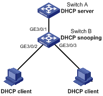
Configuration procedure
# Enable DHCP snooping.
<SwitchB> system-view
[SwitchB] dhcp-snooping
# Specify GigabitEthernet 3/0/1 as trusted.
[SwitchB] interface GigabitEthernet 3/0/1
[SwitchB-GigabitEthernet3/0/1] dhcp-snooping trust
[SwitchB-GigabitEthernet3/0/1] quit
DHCP snooping Option 82 support configuration example
Network requirements
As shown in Figure 25, DHCP snooping and Option 82 support are enabled on Switch B. The handling strategy for DHCP requests containing Option 82 is configured as replace.
On GigabitEthernet 3/0/2, configure the padding content for the circuit ID sub-option as company001 and for the remote ID sub-option as device001. On GigabitEthernet 3/0/3, configure the padding format as verbose, access node identifier as sysname, and code type as ascii for Option 82. Switch B forwards DHCP requests to the DHCP server (Switch A) after replacing Option 82 in the requests, so that the DHCP clients can obtain IP addresses.
Configuration procedure
# Enable DHCP snooping.
<SwitchB> system-view
[SwitchB] dhcp-snooping
# Specify GigabitEthernet 3/0/1 as trusted.
[SwitchB] interface GigabitEthernet 3/0/1
[SwitchB-GigabitEthernet3/0/1] dhcp-snooping trust
[SwitchB-GigabitEthernet3/0/1] quit
# Configure GigabitEthernet 3/0/2 to support Option 82.
[SwitchB] interface GigabitEthernet 3/0/2
[SwitchB-GigabitEthernet3/0/2] dhcp-snooping information enable
[SwitchB-GigabitEthernet3/0/2] dhcp-snooping information strategy replace
[SwitchB-GigabitEthernet3/0/2] dhcp-snooping information circuit-id string company001
[SwitchB-GigabitEthernet3/0/2] dhcp-snooping information remote-id string device001
[SwitchB-GigabitEthernet3/0/2] quit
# Configure GigabitEthernet 3/0/3 to support Option 82.
[SwitchB] interface GigabitEthernet 3/0/3
[SwitchB-GigabitEthernet3/0/3] dhcp-snooping information enable
[SwitchB-GigabitEthernet3/0/3] dhcp-snooping information strategy replace
[SwitchB-GigabitEthernet3/0/3] dhcp-snooping information format verbose node-identifier sysname
[SwitchB-GigabitEthernet3/0/3] dhcp-snooping information circuit-id format-type ascii
[SwitchB-GigabitEthernet3/0/3] dhcp-snooping information remote-id format-type ascii
