- Table of Contents
-
- 02-Configuration Examples
- 01-H3C_AAA_Configuration_Examples
- 02-H3C_ACL_Configuration_Examples
- 03-H3C_IGMP_Configuration_Examples
- 04-H3C_IP_Source_Guard_Configuration_Examples
- 05-H3C_Ethernet_OAM_Configuration_Examples
- 06-H3C_NQA_Configuration_Examples
- 07-H3C_QinQ_Configuration_Examples
- 08-H3C_OSPF_Configuration_Examples
- 09-H3C_MPLS_TE_Configuration_Examples
- 10-H3C_OpenFlow_Configuration_Examples
- 11-H3C_NAT_Configuration_Examples
- 12-H3C_RBAC_Configuration_Examples
- 13-H3C_DHCP_Relay_Redundancy_Configuration_Examples
- 14-H3C_DLDP_Configuration_Examples
- 15-H3C_IS-IS_Configuration_Examples
- 16-H3C_MPLS_L3VPN_Configuration_Examples
- 17-H3C_SSH_Configuration_Examples
- 18-H3C_Login_Management_Configuration_Examples
- 19-H3C_SNMP_Configuration_Examples
- 20-H3C_Priority_Marking_and_Queue_Scheduling_Configuration_Examples
- 21-H3C_Multicast_VPN_Configuration_Examples
- 22-H3C_BGP_Configuration_Examples
- 23-H3C_HoVPN_Configuration_Examples
- 24-H3C_L2TP_Configuration_Examples
- 25-H3C_VRRP_Configuration_Examples
- 26-H3C_Traffic_Filtering_Configuration_Examples
- 27-H3C_Samplers_and_IPv4_NetStream_Configuration_Examples
- 28-H3C_MPLS_L2VPN_Configuration_Examples
- 29-H3C_NetStream_Configuration_Examples
- 30-H3C_Policy-Based_Routing_Configuration_Examples
- 31-H3C_Traffic_Policing_Configuration_Examples
- 32-H3C_BFD_Configuration_Examples
- 33-H3C_OSPFv3_Configuration_Examples
- 34-H3C_VPLS_Configuration_Examples
- 35-H3C_GTS_and_Rate_Limiting_Configuration_Examples
- 36-H3C_IPv6_IS-IS_Configuration_Examples
- 37-H3C_MPLS OAM_Configuration_Examples
- 38-H3C_BGP_Route_Selection_Configuration_Examples
- 39-H3C_IS-IS_Route_Summarization_Configuration_Examples
- 40-H3C_SRv6 Configuration Examples
- 41-H3C_Attack_Protection_Configuration_Examples
- 42-H3C_OSPF_Multi-Process_Configuration_Examples
- 43-H3C_OSPF_with_Multi-Instance_Configuration_Examples
- 44-H3C_ARP_Attack_Protection_Configuration_Examples
- 45-H3C_DHCPv6_Server_and_DHCPv6_Prefix_Client_Configuration_Examples
- 46-General QoS Configuration Examples
- 47-GRE Tunnel Establishment Using OSPF Configuration Examples
- 48-GRE Tunnel Establishment Using Static Routes Configuration Examples
- 49-QoS Configuration Examples for the Financial Industry
- Related Documents
-
| Title | Size | Download |
|---|---|---|
| 13-H3C_DHCP_Relay_Redundancy_Configuration_Examples | 212.91 KB |
Introduction
The following information provides an example for configuring DHCP relay redundancy on MPLS L2VPN+L3VPN network.
Prerequisites
The configuration examples were created and verified in a lab environment, and all the devices were started with the factory default configuration. When you are working on a live network, make sure you understand the potential impact of every command on your network.
This document assumes that you have basic knowledge of MPLS L2VPN, L3VPN, and DHCP.
Example: Configuring DHCP relay redundancy on MPLS L2VPN+L3VPN network
Network configuration
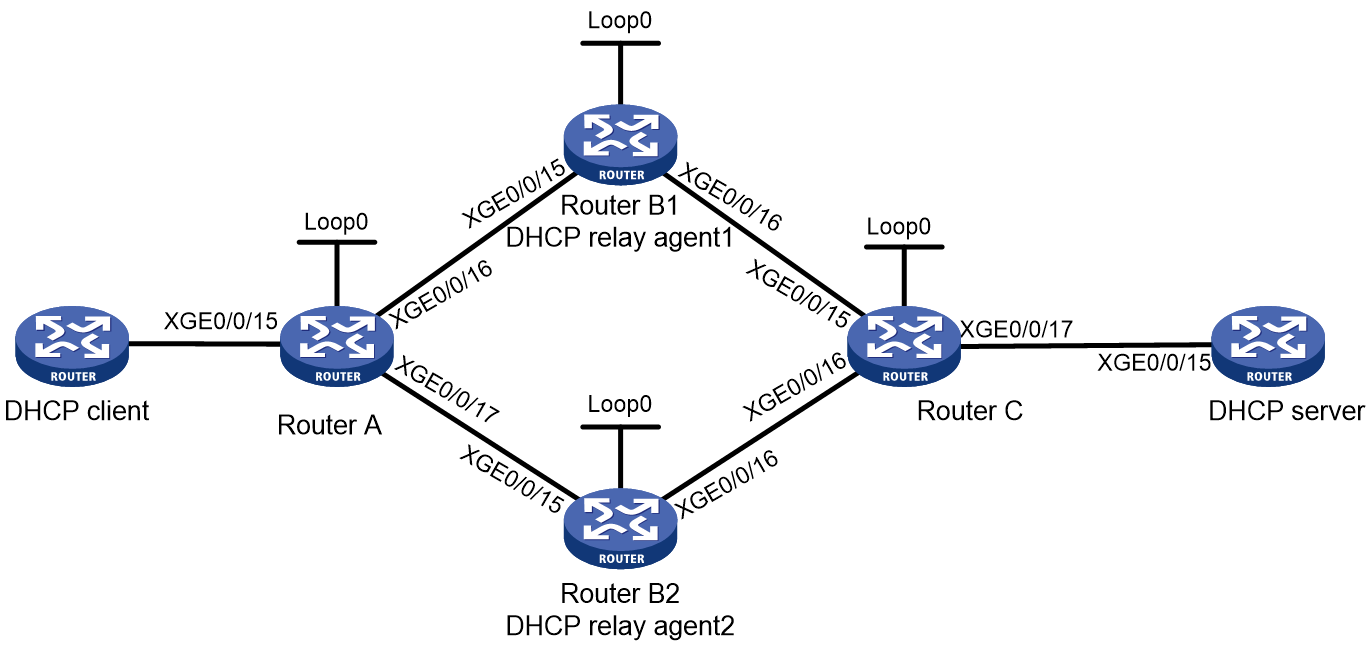
Figure 1 Network diagram
|
Device |
Interface |
IP address |
Device |
Interface |
IP address |
|
Router A |
XGE0/0/15 |
2.1.1.1/24|10::1/64 |
Router C |
XGE0/0/15 |
10.1.1.1/24|22::1/64 |
|
|
XGE0/0/16 |
2.1.1.2/24|11::1/64 |
|
XGE0/0/16 |
20.1.1.3/24|23::1/64 |
|
|
XGE0/0/17 |
3.1.1.3/24|12::1/64 |
|
XGE0/0/17 |
30.1.1.1/24|33::1/64 |
|
|
Loop0 |
1.1.1.1/32|1::1/128 |
|
Loop0 |
4.4.4.4/32|5::55/128 |
|
Router B1 |
XGE0/0/15 |
2.1.1.10/24|11::2/64 |
DHCP server |
XGE0/0/15 |
30.1.1.2/24|33::2/64 |
|
|
XGE0/0/16 |
10.1.1.10/24|22::2/64 |
|
|
|
|
|
Loop0 |
2.2.2.2/32|44::1/128 |
|
|
|
|
Router B2 |
XGE0/0/15 |
3.1.1.20/24|12::2/64 |
|
|
|
|
|
XGE0/0/16 |
20.1.1.20/24|23::2/64 |
|
|
|
|
|
Loop0 |
3.3.3.3/32|66::1/128 |
|
|
|
Analysis
· Device A and Device B communicate with each other through L2VPN by establishing LDP PWs. The two-layer label architecture is used. In this example, both the inner and outer labels are generated through LDP.
· L2VPN uses the VLL technology. Since the network has two DHCP relay agents deployed, the dual receive feature must be enabled for the primary and backup links. After the dual receive feature is enabled, both the primary and backup links can receive packets, but only the primary link sends packets.
· L3VPN is deployed between Device B and Device C. To have the MPLS network transmit packets, configure IGP on the MPLS backbone network and use LDP to distribute public-network labels. Those distributed labels will be used as the outer labels of VPN packets.
· Configure the L3VE interfaces of Device B1 and Device B2 as DHCP relay interfaces. Make sure the primary and backup DHCP relay agents use the same relay interface configuration, so users can obtain IP address from the same subnet after primary/backup switchover.
· For identification purposes, configure different source IPs for packets relayed by the primary and backup DHCP relay agents (Device B1 and Device B2). This configuration ensures that each DHCP request and DHCP reply to that request are processed by the same DHCP relay agent.
Restrictions and guidelines
When you configure an interface, first bind it to the desired VPN instance, because binding an interface to a VPN instance will clear configurations on that interface, such as IP address.
Procedure
Configuring IP addresses for interfaces
Details are not shown.
Configuring L2VPN
1. Create interfaces VE-L2VPN 7 and VE-L3VPN 7 on Router B1 and Router B2.
# Create interfaces VE-L2VPN 7 and VE-L3VPN 7 on Router B1.
<B1> system-view
[B1] interface VE-L2VPN 7
[B1-VE-L2VPN7] quit
[B1] interface VE-L3VPN 7
[B1-VE-L3VPN7] quit
# Create interfaces VE-L2VPN 7 and VE-L3VPN 7 on Router B2.
<B2> system-view
[B2] interface VE-L2VPN 7
[B2-VE-L2VPN7] quit
[B2] interface VE-L3VPN 7
[B2-VE-L3VPN7] quit
2. Configure OSPF and OSPFv3 neighbors.
# Configure Router A.
[A]ospf 1
[A-ospf-1]area 0
[A-ospf-1-area-0.0.0.0]quit
[A-ospf-1]quit
[A]ospfv3 1
[A-ospfv3-1]router-id 1.1.1.1
[A-ospfv3-1]area 0.0.0.0
[A-ospfv3-1-area-0.0.0.0]quit
[A-ospfv3-1]quit
[A]interface ten-gigabitethernet 0/0/16
[A-Ten-GigabitEthernet0/0/16]ospf 1 area 0
[A-Ten-GigabitEthernet0/0/16]ospfv3 1 area 0
[A-Ten-GigabitEthernet0/0/16]quit
[A]interface ten-gigabitethernet 0/0/17
[A-Ten-GigabitEthernet0/0/17]ospf 1 area 0
[A-Ten-GigabitEthernet0/0/17]ospfv3 1 area 0
[A-Ten-GigabitEthernet0/0/17]quit
[A]interface LoopBack 0
[A-LoopBack0]ospf 1 area 0
[A-LoopBack0]ospfv3 1 area 0
[A-LoopBack0]quit
# Configure Router B1.
[B1]ospf 1
[B1-ospf-1]area 0
[B1-ospf-1-area-0.0.0.0]quit
[B1-ospf-1]quit
[B1]ospfv3 1
[B1-ospfv3-1]router-id 2.2.2.2
[B1-ospfv3-1]area 0.0.0.0
[B1-ospfv3-1-area-0.0.0.0]quit
[B1-ospfv3-1]quit
[B1]interface ten-gigabitethernet 0/0/15
[B1-Ten-GigabitEthernet0/0/15]ospf 1 area 0
[B1-Ten-GigabitEthernet0/0/15]ospfv3 1 area 0
[B1-Ten-GigabitEthernet0/0/15]quit
[B1]interface LoopBack 0
[B1-LoopBack0]ospf 1 area 0
[B1-LoopBack0]ospfv3 1 area 0
[B1-LoopBack0]quit
# Configure Router B2.
[B2]ospf 1
[B2-ospf-1]area 0
[B2-ospf-1-area-0.0.0.0]quit
[B2-ospf-1]quit
[B2]ospfv3 1
[B2-ospfv3-1]router-id 3.3.3.3
[B2-ospfv3-1]area 0.0.0.0
[B2-ospfv3-1-area-0.0.0.0]quit
[B2-ospfv3-1]quit
[B2]interface ten-gigabitethernet 0/0/15
[B2-Ten-GigabitEthernet0/0/15]ospf 1 area 0
[B2-Ten-GigabitEthernet0/0/15]ospfv3 1 area 0
[B2-Ten-GigabitEthernet0/0/15]quit
[B2]interface LoopBack 0
[B2-LoopBack0]ospf 1 area 0
[B2-LoopBack0]ospfv3 1 area 0
[B2-LoopBack0]quit
After the configuration is completed, Router A establishes an OSPFv3 neighbor relationship with Router B1 and Router B2 separately. Output of the display ospf peer or display ospfv3 peer command shows that the neighbor relationships are in Full state. Output of the display ip routing-table or display ipv6 routing-table command shows that Router A has learned the routes to Loopback interfaces of Router B1 and Router B2.
<A>display ospf peer
OSPF Process 1 with Router ID 1.1.1.1
Neighbor Brief Information
Area: 0.0.0.0
Router ID Address Pri Dead-Time State Interface
3.3.3.3 3.1.1.20 1 38 Full/BDR XGE0/0/17
2.2.2.2 2.1.1.10 1 35 Full/DR XGE0/0/16
<A>display ip routing-table
Destinations : 12 Routes : 12
Destination/Mask Proto Pre Cost NextHop Interface
0.0.0.0/32 Direct 0 0 127.0.0.1 InLoop0
1.1.1.1/32 Direct 0 0 127.0.0.1 InLoop0
3.3.3.3/32 O_INTRA 10 1 3.1.1.20 XGE0/0/17
2.1.1.0/24 Direct 0 0 2.1.1.2 XGE0/0/16
2.1.1.0/32 Direct 0 0 2.1.1.2 XGE0/0/16
2.1.1.1/32 Direct 0 0 127.0.0.1 InLoop0
2.1.1.255/32 Direct 0 0 2.1.1.2 XGE0/0/16
3.1.1.0/24 Direct 0 0 3.1.1.3 XGE0/0/17
3.1.1.0/32 Direct 0 0 3.1.1.3 XGE0/0/17
3.1.1.1/32 Direct 0 0 127.0.0.1 InLoop0
3.1.1.255/32 Direct 0 0 3.1.1.3 XGE0/0/17
2.2.2.2/32 O_INTRA 10 1 2.1.1.10 XGE0/0/16
3. Configure basic MPLS and MPLS LDP on Router A, Router B1, and Router B2.
# Configure Router A. Make sure the LSR ID is the same as the Loopback interface IP address.
[A]mpls lsr-id 1.1.1.1
[A]mpls ldp
[A-ldp]lsp-trigger all
[A-ldp]quit
[A]interface ten-gigabitethernet 0/0/16
[A-Ten-GigabitEthernet0/0/16]mpls enable
[A-Ten-GigabitEthernet0/0/16]mpls ldp enable
[A-Ten-GigabitEthernet0/0/17]quit
[A]interface ten-gigabitethernet 0/0/17
[A-Ten-GigabitEthernet0/0/17]mpls enable
[A-Ten-GigabitEthernet0/0/17]mpls ldp enable
[A-Ten-GigabitEthernet0/0/17]quit
# Configure Router B1.
[B1]mpls lsr-id 2.2.2.2
[B1]mpls ldp
[B1-ldp]lsp-trigger all
[B1-ldp]quit
[B1]interface ten-gigabitethernet 0/0/15
[B1-Ten-GigabitEthernet0/0/15]mpls enable
[B1-Ten-GigabitEthernet0/0/15]mpls ldp enable
[B1-Ten-GigabitEthernet0/0/15]quit
# Configure Router B2.
[B2]mpls lsr-id 3.3.3.3
[B2]mpls ldp
[B2-ldp]lsp-trigger all
[B2-ldp]quit
[B2]interface ten-gigabitethernet 0/0/15
[B2-Ten-GigabitEthernet0/0/15]mpls enable
[B2-Ten-GigabitEthernet0/0/15]mpls ldp enable
[B2-Ten-GigabitEthernet0/0/15]quit
After the configuration is completed, Router A establishes an LDP session to Router B1 and Router B2 separately. Output of the display mpls ldp peer command shows that the two LDP sessions are in Operational state. Use the display mpls ldp lsp command to display information about LSPs generated by LDP.
<A>display mpls ldp peer
VPN instance: public instance
Total number of peers: 2
Peer LDP ID State Role GR Auth KA Sent/Rcvd
3.3.3.3:0 Operational Passive Off Keychain 40/40
2.2.2.2:0 Operational Passive Off Keychain 3908/3908
<A>display mpls ldp lsp
VPN instance: public instance
Status Flags: * - stale, L - liberal, B - backup, N/A - unavailable
FECs: 3 Ingress: 3 Transit: 3 Egress: 0
FEC In/Out Label Nexthop OutInterface/LSINDEX
1.1.1.1/32 4607/-
-/2517(L)
-/1279(L)
-/1430(L)
3.3.3.3/32 -/2508(L)
-/3 3.1.1.20 XGE0/0/17
4588/3 3.1.1.20 XGE0/0/17
2.2.2.2/32 -/2510(L)
-/1277(L)
-/1507 2.1.1.10 XGE0/0/16
4602/1507 2.1.1.10 XGE0/0/16
4. Enable L2VPN on Router A, Router B1, and Router B2 separately.
# Configure Router A.
[A]l2vpn enable
# Configure Router B1.
[B1]l2vpn enable
# Configure Router B2.
[B2]l2vpn enable
5. Create PWs that connect Router A to Router B1 and to Router B2.
a. Configure Router A.
# Create an AC subinterface.
[A]interface ten-gigabitethernet 0/0/15.1
[A-Ten-GigabitEthernet0/0/15.1]vlan-type dot1q vid 1
[A-Ten-GigabitEthernet0/0/15.1]quit
# Create a cross-connect group.
[A]xconnect-group ipran1
[A-xcg-ipran1]connection 1
# Configure the dual-receive feature for PW redundancy.
[A-xcg-ipran1-1]protection dual-receive
[A-xcg-ipran1-1]ac interface ten-gigabitethernet 0/0/15.1
[A-xcg-ipran1-1-Ten-GigabitEthernet0/0/15.1]quit
# Create primary and backup LDP PWs.
[A-xcg-ipran1-1]peer 2.2.2.2 pw-id 4396
[A-xcg-ipran1-1-2.2.2.2-1001]backup-peer 3.3.3.3 pw-id 4396
b. Configure Router B1.
# Create an L2VE subinterface.
[B1]interface VE-L2VPN 7.1
[B1-VE-L2VPN7.1]qos trust exp
[B1-VE-L2VPN7.1]vlan-type dot1q vid 1
[B1-VE-L2VPN7.1]quit
# Create a cross-connect group.
[B1]xconnect-group ipran
[B1-xcg-ipran]connection 1
[B1-xcg-ipran-1]ac interface VE-L2VPN7.1
[B1-xcg-ipran-1-VE-L2VPN7.1]quit
# Specify the same PW ID as Router A.
[B1-xcg-ipran-1]peer 1.1.1.1 pw-id 4396
[B1-xcg-ipran-1-1.1.1.1-4396]quit
[B1-xcg-ipran-1]quit
[B1-xcg-ipran]quit
c. Configure Router B2.
# Create an L2VE subinterface.
[B2]interface VE-L2VPN 7.1
[B2-VE-L2VPN7.1]qos trust exp
[B2-VE-L2VPN7.1]vlan-type dot1q vid 1
[B2-VE-L2VPN7.1]quit
# Create a cross-connect group.
[B2]xconnect-group ipran
[B2-xcg-ipran]connection 1
[B2-xcg-ipran-1]ac interface VE-L2VPN7.1
[B2-xcg-ipran-1-VE-L2VPN7.1]quit
[B2-xcg-ipran-1]peer 1.1.1.1 pw-id 4396
[B2-xcg-ipran-1-1.1.1.1-4396]quit
[B2-xcg-ipran-1]quit
[B2-xcg-ipran]quit
After the configuration is completed, a PW is established between Router A and Router B1, and between Router A and Router B2, separately. Output of the display l2vpn pw xconnect-group ipran command shows that the primary PW is in Up state and the backup PW is in Blocked state.
<A>display l2vpn pw xconnect-group ipran
Flags: M - main, B - backup, E - ecmp, BY - bypass, H - hub link, S - spoke link
N - no split horizon, A - administration, ABY - ac-bypass
PBY - pw-bypass
Total number of PWs: 2
1 up, 1 blocked, 0 down, 0 defect, 0 idle, 0 duplicate
Xconnect-group Name: ipran
Peer PWID/RmtSite/SrvID In/Out Label Proto Flag Link ID State
2.2.2.2 4396 26473/3006 LDP M 1 Up
3.3.3.3 4396 26472/1149 LDP B 1 Blocked
Configuring L3VPN
1. Configure IS-IS neighbors.
# Configure Router B1.
[B1]isis 1
[B1-isis-1]network-entity 10.0000.0000.0002.00
[B1-isis-1]is-level level-2
[B1-isis-1]address-family ipv4 unicast
[B1-isis-1-ipv4]quit
[B1-isis-1]address-family ipv6 unicast
[B1-isis-1-ipv6]quit
[B1-isis-1]quit
[B1]interface ten-gigabitethernet 0/0/16
[B1-Ten-GigabitEthernet0/0/16]isis enable 1
[B1-Ten-GigabitEthernet0/0/16]isis ipv6 enable 1
[B1-Ten-GigabitEthernet0/0/16]isis circuit-level level-2
[B1-Ten-GigabitEthernet0/0/16]quit
[B1]interface LoopBack 0
[B1-LoopBack0]isis enable 1
[B1-LoopBack0]isis ipv6 enable 1
[B1-LoopBack0]isis circuit-level level-2
[B1-LoopBack0]quit
# Configure Router B2.
[B2]isis 1
[B2-isis-1]network-entity 10.0000.0000.0012.00
[B2-isis-1]is-level level-2
[B2-isis-1]address-family ipv4 unicast
[B2-isis-1-ipv4]quit
[B2-isis-1]address-family ipv6 unicast
[B2-isis-1-ipv6]quit
[B2-isis-1]quit
[B2]interface ten-gigabitethernet 0/0/16
[B2-Ten-GigabitEthernet0/0/16]isis enable 1
[B2-Ten-GigabitEthernet0/0/16]isis ipv6 enable 1
[B2-Ten-GigabitEthernet0/0/16]isis circuit-level level-2
[B2-Ten-GigabitEthernet0/0/16]quit
[B2]interface LoopBack 0
[B2-LoopBack0]isis enable 1
[B2-LoopBack0]isis ipv6 enable 1
[B2-LoopBack0]isis circuit-level level-2
[B2-LoopBack0]quit
# Configure Router C.
[C]isis 1
[C-isis-1]network-entity 10.0000.0000.0004.00
[C-isis-1]is-level level-2
[C-isis-1]address-family ipv4 unicast
[C-isis-1-ipv4]quit
[C-isis-1]address-family ipv6 unicast
[C-isis-1-ipv6]quit
[C-isis-1]quit
[C]interface ten-gigabitethernet 0/0/15
[C-Ten-GigabitEthernet0/0/15]isis enable 1
[C-Ten-GigabitEthernet0/0/15]isis ipv6 enable 1
[C-Ten-GigabitEthernet0/0/15]isis circuit-level level-2
[C-Ten-GigabitEthernet0/0/15]quit
[C]interface ten-gigabitethernet 0/0/16
[C-Ten-GigabitEthernet0/0/16]isis enable 1
[C-Ten-GigabitEthernet0/0/16]isis ipv6 enable 1
[C-Ten-GigabitEthernet0/0/16]isis circuit-level level-2
[C-Ten-GigabitEthernet0/0/16]quit
[C]interface LoopBack 0
[C-LoopBack0]isis enable 1
[C-LoopBack0]isis ipv6 enable 1
[C-LoopBack0]isis circuit-level level-2
[C-LoopBack0]quit
After the configuration is completed, Router C establish an IS-IS neighbor relationship with Router B1 and Router B2 separately. Output of the display isis peer command shows that the two IS-IS neighbor relationships are in UP state. Output of the display ip routing-table command shows that Router C has learned the routes to Loopback interfaces of Router B1 and Router B2.
<C>display isis peer
Peer information for IS-IS(1)
-----------------------------
System ID: 0000.0000.0012
Interface: XGE0/0/16 Circuit Id: 0000.0000.0012.01
State: Up HoldTime: 8s Type: L2 PRI: 64
System ID: 0000.0000.0002
Interface: XGE0/0/15 Circuit Id: 0000.0000.0002.05
State: Up HoldTime: 6s Type: L2 PRI: 64
<C>display ip routing-table
Destinations : 12 Routes : 12
Destination/Mask Proto Pre Cost NextHop Interface
0.0.0.0/32 Direct 0 0 127.0.0.1 InLoop0
4.4.4.4/32 Direct 0 0 127.0.0.1 InLoop0
3.3.3.3/32 IS_L2 15 10 20.1.1.20 XGE0/0/16
10.1.1.0/24 Direct 0 0 10.1.1.1 XGE0/0/15
10.1.1.0/32 Direct 0 0 10.1.1.1 XGE0/0/15
10.1.1.1/32 Direct 0 0 127.0.0.1 InLoop0
10.1.1.255/32 Direct 0 0 10.1.1.1 XGE0/0/15
20.1.1.0/24 Direct 0 0 20.1.1.3 XGE0/0/16
20.1.1.0/32 Direct 0 0 20.1.1.3 XGE0/0/16
20.1.1.1/32 Direct 0 0 127.0.0.1 InLoop0
20.1.1.255/32 Direct 0 0 20.1.1.3 XGE0/0/16
2.2.2.2/32 IS_L2 15 10 10.1.1.10 XGE0/0/15
2. Configure basic MPLS and MPLS LDP.
# Configure Router B1.
[B1]interface ten-gigabitethernet 0/0/16
[B1-Ten-GigabitEthernet0/0/16]mpls enable
[B1-Ten-GigabitEthernet0/0/16]mpls ldp enable
[B1-Ten-GigabitEthernet0/0/16]quit
# Configure Router B2.
[B2]interface ten-gigabitethernet 0/0/16
[B2-Ten-GigabitEthernet0/0/16]mpls enable
[B2-Ten-GigabitEthernet0/0/16]mpls ldp enable
[B2-Ten-GigabitEthernet0/0/16]quit
# Configure Router C. Make sure the LSR ID is the same as the Loopback interface IP address.
[C]mpls lsr-id 4.4.4.4
[C]mpls ldp
[C-ldp]lsp-trigger all
[C-ldp]quit
[C]interface ten-gigabitethernet 0/0/15
[C-Ten-GigabitEthernet0/0/15]mpls enable
[C-Ten-GigabitEthernet0/0/15]mpls ldp enable
[C-Ten-GigabitEthernet0/0/15]quit
3. Create a VPN instance.
# Configure Router B1.
[B1]ip vpn-instance ipran
[B1-vpn-instance-ipran]route-distinguisher 207:1
[B1-vpn-instance-ipran]vpn-target 117:1 both
[B1-vpn-instance-ipran]quit
[B1]interface VE-L3VPN 7
[B1-VE-L3VPN7]ip binding vpn-instance ipran
[B1-VE-L3VPN7]ip address 25.2.0.1 24
[B1-VE-L3VPN7]mac-address 586a-b100-0001
[B1-VE-L3VPN7]ipv6 address 6::1 64
[B1-VE-L3VPN7]quit
# Configure Router B2.
[B2]ip vpn-instance ipran
[B2-vpn-instance-ipran]route-distinguisher 207:1
[B2-vpn-instance-ipran]vpn-target 117:1 both
[B2-vpn-instance-ipran]quit
[B2]interface VE-L3VPN 7
[B2-VE-L3VPN7]ip binding vpn-instance ipran
[B2-VE-L3VPN7]ip address 25.2.0.1 24
[B2-VE-L3VPN7]mac-address 586a-b100-0001
[B2-VE-L3VPN7]ipv6 address 6::1 64
[B2-VE-L3VPN7]quit
# Configure Router C.
[C]ip vpn-instance ipran
[C-vpn-instance-ipran]route-distinguisher 207:1
[C-vpn-instance-ipran]vpn-target 117:1 both
[C-vpn-instance-ipran]quit
[C]interface ten-gigabitethernet 0/0/17
[C-Ten-GigabitEthernet0/0/17]ip binding vpn-instance ipran
[C-Ten-GigabitEthernet0/0/17]ip address 30.1.1.1 255.255.255.0
[C-Ten-GigabitEthernet0/0/17]ipv6 address 3::1/64
[C-Ten-GigabitEthernet0/0/17]quit
4. Configure IBGP peers.
a. Configure Router B1.
# Configure IBGP peers.
[B1]bgp 100
[B1-bgp-default]peer 4.4.4.4 as-number 100
[B1-bgp-default]peer 4.4.4.4 connect-interface LoopBack0
[B1-bgp-default]address-family vpnv4
[B1-bgp-default-vpnv4]peer 4.4.4.4 enable
[B2-bgp-default-vpnv4]quit
[B2-bgp-default]address-family vpnv6
[B1-bgp-default-vpnv6]peer 4.4.4.4 enable
[B1-bgp-default-vpnv6]quit
# Redistribute direct routes to the related VPN instance.
[B1-bgp-default]ip vpn-instance ipran
[B1-bgp-default-ipran]address-family ipv4 unicast
[B1-bgp-default-ipv4-ipran]import-route direct
[B1-bgp-default-ipv4-ipran]quit
[B1-bgp-default-ipran]address-family ipv6 unicast
[B1-bgp-default-ipv6-ipran]import-route direct
[B1-bgp-default-ipv6-ipran]quit
[B1-bgp-default-ipran]quit
[B1-bgp-default]quit
b. Configure Router B2.
# Configure IBGP peers.
[B2]bgp 100
[B2-bgp-default]peer 4.4.4.4 as-number 100
[B2-bgp-default]peer 4.4.4.4 connect-interface LoopBack 0
[B2-bgp-default]address-family vpnv4
[B2-bgp-default-vpnv4]peer 4.4.4.4 enable
[B2-bgp-default-vpnv4]quit
[B2-bgp-default]address-family vpnv6
[B2-bgp-default-vpnv6]peer 4.4.4.4 enable
[B2-bgp-default-vpnv6]quit
# Redistribute direct routes to the related VPN instance.
[B2-bgp-default]ip vpn-instance ipran
[B2-bgp-default-ipran]address-family ipv4 unicast
[B2-bgp-default-ipv4-ipran]import-route direct
[B2-bgp-default-ipv4-ipran]quit
[B2-bgp-default-ipran]address-family ipv6 unicast
[B2-bgp-default-ipv6-ipran]import-route direct
[B2-bgp-default-ipv6-ipran]quit
[B2-bgp-default-ipran]quit
[B2-bgp-default]quit
c. Configure Router C.
# Configure IBGP peers.
[C]bgp 100
[C-bgp-default]peer 2.2.2.2 as-number 100
[C-bgp-default]peer 2.2.2.2 connect-interface LoopBack 0
[C-bgp-default]peer 3.3.3.3 as-number 100
[C-bgp-default]peer 3.3.3.3 connect-interface LoopBack 0
[C-bgp-default]address-family vpnv4
[C-bgp-default-vpnv4]peer 2.2.2.2 enable
[C-bgp-default-vpnv4]peer 3.3.3.3 enable
[C-bgp-default-vpnv4]quit
[C-bgp-default]address-family vpnv6
[C-bgp-default-vpnv6]peer 2.2.2.2 enable
[C-bgp-default-vpnv6]peer 3.3.3.3 enable
[C-bgp-default-vpnv6]quit
# Redistribute direct routes to the related VPN instance.
[C-bgp-default]ip vpn-instance ipran
[C-bgp-default-ipran]address-family ipv4 unicast
[C-bgp-default-ipv4-ipran]import-route direct
[C-bgp-default-ipv4-ipran]quit
[C-bgp-default-ipran]address-family ipv6 unicast
[C-bgp-default-ipv6-ipran]import-route direct
[C-bgp-default-ipv6-ipran]quit
[C-bgp-default-ipran]quit
[C-bgp-default]quit
After the configuration is completed, Router C establishes an IBGP peer relationship with Router B1 and Router B2 separately. Outputs of the display bgp peer vpnv4 and display bgp peer vpnv6 commands show that the IBGP peer relationships are all in Established state.
<C>display bgp peer vpnv4
BGP local router ID: 4.4.4.4
Local AS number: 100
Total number of peers: 2 Peers in established state: 2
* - Dynamically created peer
Peer AS MsgRcvd MsgSent OutQ PrefRcv Up/Down State
3.3.3.3 100 105 120 0 0 01:32:51 Established
2.2.2.2 100 1550 1241 0 1 19:33:46 Established
<C>display bgp peer vpnv6
BGP local router ID: 4.4.4.4
Local AS number: 100
Total number of peers: 2 Peers in established state: 2
* - Dynamically created peer
Peer AS MsgRcvd MsgSent OutQ PrefRcv Up/Down State
3.3.3.3 100 106 121 0 0 01:33:32 Established
2.2.2.2 100 1551 1242 0 1 19:34:27 Established
Configuring DHCP
1. Configure the DHCP relay agent.
a. Configure Router B1.
# Configure the DHCPv4 relay settings.
<B1> system-view
[B1] dhcp enable
[B1] interface VE-L3VPN 7
[B1-VE-L3VPN7]dhcp select relay
[B1-VE-L3VPN7]dhcp relay information enable
[B1-VE-L3VPN7]dhcp relay server-address 30.1.1.2
[B1-VE-L3VPN7]dhcp relay source-address 44.4.0.1
[B1-VE-L3VPN7]ip address 44.4.0.1 24 sub
# Configure the DHCPv6 relay settings.
[B1-VE-L3VPN7]ipv6 nd autoconfig managed-address-flag
[B1-VE-L3VPN7]ipv6 nd autoconfig other-flag
[B1-VE-L3VPN7]undo ipv6 nd ra halt
[B1-VE-L3VPN7]ipv6 dhcp select relay
[B1-VE-L3VPN7]ipv6 dhcp relay server-address 33::2
[B1-VE-L3VPN7]ipv6 dhcp relay source-address 44::1
[B1-VE-L3VPN7]quit
# Configure an IPv6 address for the Loopback interface. This configuration ensures that the related DHCPv6 routes are reachable.
[B1]interface LoopBack 7
[B1-LoopBack7]ip binding vpn-instance ipran
[B1-LoopBack7]ipv6 address 44::1 128
[B1-LoopBack7]quit
b. Configure Router B2.
# Configure the DHCPv4 relay settings.
<B2> system-view
[B1] dhcp enable
[B2] interface VE-L3VPN 7
[B2-VE-L3VPN7]dhcp select relay
[B2-VE-L3VPN7]dhcp relay information enable
[B2-VE-L3VPN7]dhcp relay server-address 30.1.1.2
[B2-VE-L3VPN7]dhcp relay source-address 45.4.0.1
[B2-VE-L3VPN7]ip address 45.4.0.1 24 sub
# Configure the DHCPv6 relay settings.
[B2-VE-L3VPN7]ipv6 nd autoconfig managed-address-flag
[B2-VE-L3VPN7]ipv6 nd autoconfig other-flag
[B2-VE-L3VPN7]undo ipv6 nd ra halt
[B2-VE-L3VPN7]ipv6 dhcp select relay
[B2-VE-L3VPN7]ipv6 dhcp relay server-address 33::2
[B2-VE-L3VPN7]ipv6 dhcp relay source-address 45::1
[B2-VE-L3VPN7]quit
# Configure an IPv6 address for the Loopback interface. This configuration ensures that the related DHCPv6 routes are reachable.
[B2]interface LoopBack 7
[B2-LoopBack7]ip binding vpn-instance ipran
[B2-LoopBack7]ipv6 address 45::1 128
[B2-LoopBack7]quit
2. Configure the DHCP server.
# Configure a DHCPv4 address pool.
[server]dhcp enable
[server]ip pool poolv4
[server-ip-pool-poolv4]gateway-list 25.2.0.1
[server-ip-pool-poolv4]network 25.2.0.1 24
[server-ip-pool-poolv4]forbidden-ip 25.2.0.1
[server-ip-pool-poolv4]quit
# Configure a DHCPv6 address pool.
[server]ipv6 pool poolv6
[server-ipv6-pool-poolv6]network 6::/64
[server-ipv6-pool-poolv6]gateway-list 6::1
[server-ipv6-pool-poolv6]quit
# Enable the DHCPv6 server.
[server]interface ten-gigabitethernet 0/0/15
[server-Ten-GigabitEthernet0/0/15]ipv6 dhcp select server
[server-Ten-GigabitEthernet0/0/15]quit
# Configure static routes.
[server]ip route-static 25.2.0.0 24 30.1.1.1
[server]ip route-static 44.4.0.0 24 30.1.1.1
[server]ip route-static 45.4.0.0 24 30.1.1.1
[server]ipv6 route-static 6:: 64 33::1
[server]ipv6 route-static 44::1 128 33::1
[server]ipv6 route-static 45::1 128 33::1
Verifying the configuration
On the DHCP server, execute the display dhcp server ip-in-use command to view the assigned IPv4 addresses and the display ipv6 dhcp server ip-in-use command to view the assigned IPv6 addresses.
[server]display dhcp server ip-in-use
IP address Client identifier/ Lease expiration Type
Hardware address
25.2.0.2 0100-1094-1a7d-f5 Dec 19 10:14:27 2019 Auto(C)
[server]display ipv6 dhcp server ip-in-use
Pool: poolv6
IPv6 address Type Lease expiration DUID
6::2 Auto(C) Jan 18 09:59:55 2020 0003000211df605b0300
Configuration files
Router A
#
interface ten-gigabitethernet 0/0/17
port link-mode route
ip address 3.1.1.3 255.255.255.0
ospf 1 area 0.0.0.0
ospfv3 1 area 0.0.0.0
mpls enable
mpls ldp enable
ipv6 address 12::1/64
#
#
interface ten-gigabitethernet 0/0/16
port link-mode route
ip address 2.1.1.2 255.255.255.0
ospf 1 area 0.0.0.0
ospfv3 1 area 0.0.0.0
mpls enable
mpls ldp enable
ipv6 address 11::1/64
#
#
interface LoopBack0
ip address 1.1.1.1 255.255.255.255
ospf 1 prefix-sid index 200 no-php
ospf 1 area 0.0.0.0
ipv6 address 1::1/128
#
#
ospf 1 router-id 1.1.1.1
area 0.0.0.0
#
#
ospfv3 1
router-id 1.1.1.1
area 0.0.0.0
#
#
interface ten-gigabitethernet 0/0/15.1
vlan-type dot1q vid 1
#
#
xconnect-group ipran
connection 1
protection dual-receive
ac interface ten-gigabitethernet 0/0/15.1
peer 2.2.2.2 pw-id 4396
backup-peer 3.3.3.3 pw-id 4396
#
Router B1
#
dhcp enable
#
#
interface ten-gigabitethernet 0/0/15
port link-mode route
ip address 2.1.1.10 255.255.255.0
ospf 1 area 0.0.0.0
ospfv3 1 area 0.0.0.0
mpls enable
mpls ldp enable
ipv6 address 11::2/64
#
#
interface ten-gigabitethernet 0/0/16
port link-mode route
ip address 10.1.1.10 255.255.255.0
isis enable 1
isis ipv6 enable 1
isis circuit-level level-2
mpls enable
mpls ldp enable
ipv6 address 22::2/64
#
#
interface LoopBack0
ip address 2.2.2.2 255.255.255.255
ospf 1 area 0.0.0.0
ospfv3 1 area 0.0.0.0
isis enable 1
isis ipv6 enable 1
isis circuit-level level-2
ipv6 address 44::1/128
#
#
interface VE-L3VPN7
ip binding vpn-instance ipran
ip address 25.2.0.1 255.255.255.0
ip address 44.4.0.1 255.255.255.0 sub
mac-address 586a-b100-0001
dhcp relay source-address 44.4.0.1
dhcp select relay
dhcp relay information enable
dhcp relay server-address 30.1.1.2
ipv6 dhcp select relay
ipv6 dhcp relay source-address 44::1
ipv6 dhcp relay server-address 33::2
ipv6 address 6::1/64
ipv6 nd autoconfig managed-address-flag
ipv6 nd autoconfig other-flag
undo ipv6 nd ra halt
#
#
interface LoopBack7
ip binding vpn-instance ipran
ipv6 address 44::1/128
#
#
interface VE-L2VPN7.1
qos trust exp
vlan-type dot1q vid 1
#
#
xconnect-group ipran
connection 1
ac interface VE-L2VPN7.1
peer 1.1.1.1 pw-id 4396
#
#
ospf 1 router-id 2.2.2.2
area 0.0.0.0
#
#
ospfv3 1
router-id 2.2.2.2
area 0.0.0.0
#
#
isis 1
is-level level-2
network-entity 10.0000.0000.0002.00
#
address-family ipv4 unicast
#
address-family ipv6 unicast
##
bgp 100
peer 4.4.4.4 as-number 100
peer 4.4.4.4 connect-interface LoopBack0
#
address-family vpnv4
peer 4.4.4.4 enable
#
address-family vpnv6
peer 4.4.4.4 enable
#
ip vpn-instance ipran
#
address-family ipv4 unicast
import-route direct
#
address-family vpnv4
#
address-family ipv6 unicast
import-route direct
#
Router B2
#
dhcp enable
#
#
interface ten-gigabitethernet 0/0/15
port link-mode route
ip address 3.1.1.20 255.255.255.0
ospf 1 area 0.0.0.0
ospfv3 1 area 0.0.0.0
mpls enable
mpls ldp enable
ipv6 address 12::2/64
#
#
interface ten-gigabitethernet 0/0/16
port link-mode route
ip address 20.1.1.20 255.255.255.0
isis enable 1
isis ipv6 enable 1
isis circuit-level level-2
mpls enable
mpls ldp enable
ipv6 address 23::2/64
#
#
interface LoopBack0
ip address 3.3.3.3 255.255.255.255
ospf 1 area 0.0.0.0
ospfv3 1 area 0.0.0.0
isis enable 1
isis ipv6 enable 1
isis circuit-level level-2
ipv6 address 66::1/128
#
#
interface VE-L3VPN7
shutdown
ip binding vpn-instance ipran
ip address 25.2.0.1 255.255.0.0
ip address 45.4.0.1 255.255.255.0 sub
mac-address 586a-b100-0001
dhcp relay source-address 45.4.0.1
dhcp select relay
dhcp relay information enable
dhcp relay server-address 30.1.1.2
ipv6 dhcp select relay
ipv6 dhcp relay source-address 45::1
ipv6 dhcp relay server-address 33::2
ipv6 address 6::1/64
ipv6 nd autoconfig managed-address-flag
ipv6 nd autoconfig other-flag
undo ipv6 nd ra halt
#
#
interface LoopBack7
ip binding vpn-instance ipran
ipv6 address 45::1/128
#
#
interface VE-L2VPN7.1
qos trust exp
vlan-type dot1q vid 1
#
#
xconnect-group ipran
connection 1
ac interface VE-L2VPN7.1
peer 1.1.1.1 pw-id 4396
#
#
ospf 1
non-stop-routing
area 0.0.0.0
#
#
ospfv3 1
router-id 3.3.3.3
non-stop-routing
import-route static
area 0.0.0.0
#
#
isis 1
is-level level-2
network-entity 10.0000.0000.0012.00
#
address-family ipv4 unicast
#
address-family ipv6 unicast
#
#
bgp 100
peer 4.4.4.4 as-number 100
peer 4.4.4.4 connect-interface LoopBack0
#
address-family ipv4 unicast
import-route direct
#
address-family vpnv4
peer 4.4.4.4 enable
#
address-family ipv6 unicast
import-route direct
#
address-family vpnv6
peer 4.4.4.4 enable
#
ip vpn-instance ipran
#
address-family ipv4 unicast
import-route direct
#
address-family vpnv4
#
address-family ipv6 unicast
import-route direct
#
Router C
#
interface ten-gigabitethernet 0/0/16
port link-mode route
ip address 20.1.1.3 255.255.255.0
isis enable 1
isis ipv6 enable 1
isis circuit-level level-2
mpls enable
mpls ldp enable
ipv6 address 23::1/64
#
#
interface ten-gigabitethernet 0/0/15
port link-mode route
ip address 10.1.1.1 255.255.255.0
isis enable 1
isis ipv6 enable 1
isis circuit-level level-2
mpls enable
mpls ldp enable
ipv6 address 22::1/64
#
#
interface ten-gigabitethernet 0/0/17
port link-mode route
ip binding vpn-instance ipran
ip address 30.1.1.1 255.255.255.0
ipv6 address 33::1/64
#
#
interface LoopBack0
ip address 4.4.4.4 255.255.255.255
isis enable 1
isis ipv6 enable 1
isis circuit-level level-2
ipv6 address 5::55/128
#
#
bgp 100
peer 3.3.3.3 as-number 100
peer 3.3.3.3 connect-interface LoopBack0
peer 2.2.2.2 as-number 100
peer 2.2.2.2 connect-interface LoopBack0
#
address-family ipv4 unicast
#
address-family vpnv4
peer 3.3.3.3 enable
peer 2.2.2.2 enable
#
address-family vpnv6
peer 3.3.3.3 enable
peer 2.2.2.2 enable
ip vpn-instance ipran
#
address-family ipv4 unicast
import-route direct
#
address-family vpnv4
#
address-family ipv6 unicast
import-route direct
#
Server
#
dhcp enable
#
ip pool pool3
gateway-list 25.2.0.1
network 25.2.0.0 mask 255.255.0.0
forbidden-ip 25.2.0.1
#
#
ipv6 pool poolv6
network 6::/64
gateway-list 6::1
#
#
interface ten-gigabitethernet 0/0/15
port link-mode route
ip address 30.1.1.2 255.255.255.0
ipv6 dhcp select server
ipv6 address 33::2/64
#
Related documentation
· H3C CR16000-M1A Routers MPLS Configuration Guide
· H3C CR16000-M1A Routers MPLS Command Reference
· H3C CR16000-M1A Routers DHCP Configuration Guide
· H3C CR16000-M1A Routers DHCP Command Reference
