- Table of Contents
- Related Documents
-
| Title | Size | Download |
|---|---|---|
| 01-Text | 12.76 MB |
Content
Log in to UniSystem (non-unified O&M version)
Log in to the UniSystem Web interface
Log in to UniSystem (unified O&M version)
Set up the hardware environment
Log in to the UniSystem Web interface
UniSystem Web interface layout
General restrictions and guidelines
Manage servers remotely through UniSystem
Use the switch management functions
More options for an infrastructure device
Manage custom monitoring templates
View equipment room information
View enclosure template information
About server template management
Configure RAID configuration templates
(Optional) Create a custom repository or ISO file
Access the switch template list page
Manage interconnect module templates
Apply an enclosure template to enclosures
Enclosure slot configuration files
Apply a server template to servers
View a server configuration file
Edit a server configuration file
Apply server configuration files
Delete server configuration files
Update the firmware by using HDM out-of-band management
Server software license management
Configure the noise reduction policy
Configure notification policies
Manage energy efficiency and prediction (G6 and later servers)
Configure inlet temperature analysis
Configure server usage analysis
Perform one-key power consumption limit
Cabinet intelligent power management
About cabinet intelligent power management
View detailed information about an inspection task
Configure the DHCP server settings
View the DHCP client information
Configure static IP allocation
Configure PXE OS installation parameters
Incorporate UniSystem to vCenter Server as a UniSystem plugin
Installing the UniSystem plugin
Uninstalling the UniSystem plugin
Configure the network settings
View basic Ethernet adapter information
Set the host name for UniSystem
Set the IP address obtaining method for a network port and the DNS server address
Synchronize the system time with an NTP server
Back up and restore UniSystem data
Configure the security tip for login
View the current menu and all menu items
Email notification configuration
SMS message notification configuration
WeCom notification configuration
WhatsApp notification configuration
Webhook notification configuration
Syslog forwarding configuration
View LDAP server information and test connectivity to a server
Introduction
The UniSystem is intelligent, extensible server management software that allows customers to manage servers remotely from a unified, intuitive graphical user interface.
Architecture
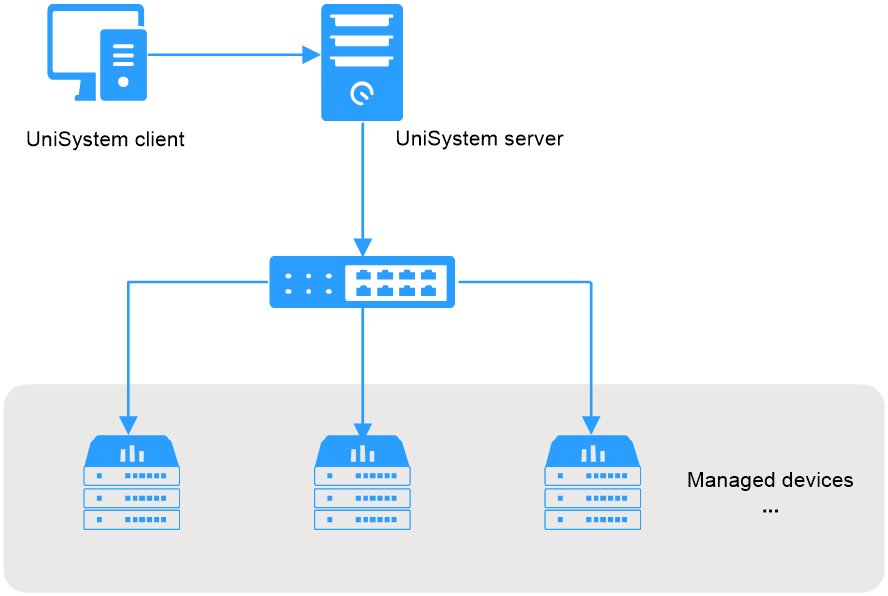
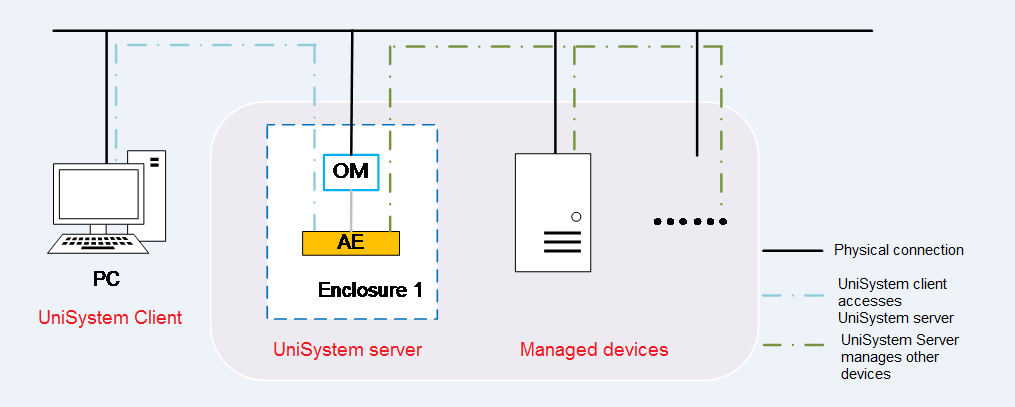
As shown in Figure 1, the UniSystem architecture contains the following elements:
· UniSystem client—An endpoint device (such as a PC) used to access UniSystem through the Web browser.
· UniSystem server—A PC, physical server, AE module, or VM hosting the UniSystem server software. The AE module ships with UniSystem pre-installed.
· Managed devices—Devices managed by UniSystem.
The UniSystem client and UniSystem server can reside on the same device, which means that you can access UniSystem from the browser of the host where the UniSystem server resides.
Figure 1 UniSystem architecture
Features
UniSystem offers the following features:
· Devices—Allows you to centrally manage enclosures, servers, and switches in UniSystem. You can add devices to UniSystem, view information about the devices managed by UniSystem, and manage the devices.
· Templates—Allows you to define templates to deploy BIOS, HDM, RAID, and operating system settings to servers.
· Deployment—Allows you to apply server and enclosure templates for bulk device configuration, and deploy component updates such as firmware and driver updates to servers.
· Monitor—Provides the following capabilities:
¡ Provides visibility into the status of managed servers through reports and operation logs.
¡ Supports forwarding alarms to designated email recipients based on user-defined alarm email notification settings.
The monitor functions help troubleshoot problems and improve operations and maintenance efficiency.
· Asset management—Provides features such as asset overview, asset inventory, and asset inspection to comprehensively monitor and manage assets, gain real-time insights into asset status, and optimize resource utilization.
· Tools—Allows you to configure management tools, including the DHCP server, PXE, and FIST SMS.
· System—Provides UniSystem system configuration and management options. For example, you can configure the system time, network, and backup and restore settings for UniSystem. You can also manage user accounts in UniSystem and set up a UniSystem cluster by teaming up the UniSystem node up with a secondary node.
Application scenarios
UniSystem is a bulk server management tool that can help enterprises manage, monitor, update, and query resources more effectively to simplify device management.
The H3C UniServer B16000 AE module comes with UniSystem pre-installed. UniSystem embedded within an AE module can manage not only local enclosures, but also blade servers, rack servers, and switches in the enclosures. UniSystem in an AE module supports hybrid IT architecture and cluster-mode management.
Applicable products
This document is applicable to the following products:
· AE modules
· H3C UniServer B16000
· H3C UniServer R5300 G7
· H3C UniServer R5500 G7
· H3C UniServer R4330 G7
· H3C UniServer R4930 G7
· H3C UniServer R4970 G7
· H3C UniServer B5700 G6
· H3C UniServer E3300 G6
· H3C UniServer R3950 G6
· H3C UniServer R4300 G6
· H3C UniServer R4500 G6
· H3C UniServer R4700 G6
· H3C UniServer R4700LE G6
· H3C UniServer R4900 G6
· H3C UniServer R4900LE G6 Ultra
· H3C UniServer R4900 G6 Ultra
· H3C UniServer R4950 G6
· H3C UniServer R5350 G6
· H3C UniServer R5300 G6
· H3C UniServer R5500 G6 AMD
· H3C UniServer R5500 G6 Intel
· H3C UniServer R6700 G6
· H3C UniServer R6900 G6
· H3C UniServer B5700 G5
· H3C UniServer R4300 G5
· H3C UniServer R4330 G5
· H3C UniServer R4330 G5 H3
· H3C UniServer R4700 G5
· H3C UniServer R4700LC G5
· H3C UniServer R4900 G5
· H3C UniServer R4900LC G5
· H3C UniServer R4930 G5
· H3C UniServer R4930 G5 H3
· H3C UniServer R4930 G5 H3 PKG
· H3C UniServer R4930LC G5 H3
· H3C UniServer R4950 G5
· H3C UniServer R5300 G5
· H3C UniServer R5500 G5
· H3C UniServer R5500LC G5
· H3C UniServer R6900 G5
· H3C UniServer B5700 G3
· H3C UniServer B5800 G3
· H3C UniServer B7800 G3
· H3C UniServer E3200 G3
· H3C UniServer R2700 G3
· H3C UniServer R2900 G3
· H3C UniServer R4300 G3
· H3C UniServer R4360 G3
· H3C UniServer R4500 G3
· H3C UniServer R4700 G3
· H3C UniServer R4900 G3
· H3C UniServer R4950 G3
· H3C UniServer R4960 G3
· H3C UniServer R5300 G3
· H3C UniServer R6700 G3
· H3C UniServer R6900 G3
· H3C UniServer R8900 G3
· H3C UniStor X10828 G5
· H3C UniStor X10516 G6
· H3C UniStor X10529 G6
· H3C UniStor X10536 G6
· H3C UniStor X18000 G6
Guidelines
The information in this document might differ from your product if it contains custom configuration options or features.
The model name of a hardware option in this document might differ slightly from its model name label. A model name label might add a prefix or suffix to the hardware-coded model name for purposes such as identifying the matching server brand or applicable region. For example, storage controller model HBA-1000-M2-1 represents storage controller model label UN-HBA-1000-M2-1, which has a prefix of UN-.
The webpage screenshots used in this document are for illustration only and might differ from your products.
Log in to UniSystem
Log in to UniSystem (non-unified O&M version)
Prepare for a UniSystem login
Connect the UniSystem server to the network
To log in to UniSystem running on a PC or a server, just make sure the UniSystem client and UniSystem server reside on the same network segment.
To log in to UniSystem running on an AE module, complete the following tasks first:
1. Make sure the enclosure has a minimum of one AE module present.
An enclosure supports a maximum of two AE modules, as shown in Figure 2.
Figure 2 AE module slots
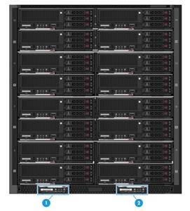
|
(1) Slot E1 |
(2) Slot E2 |
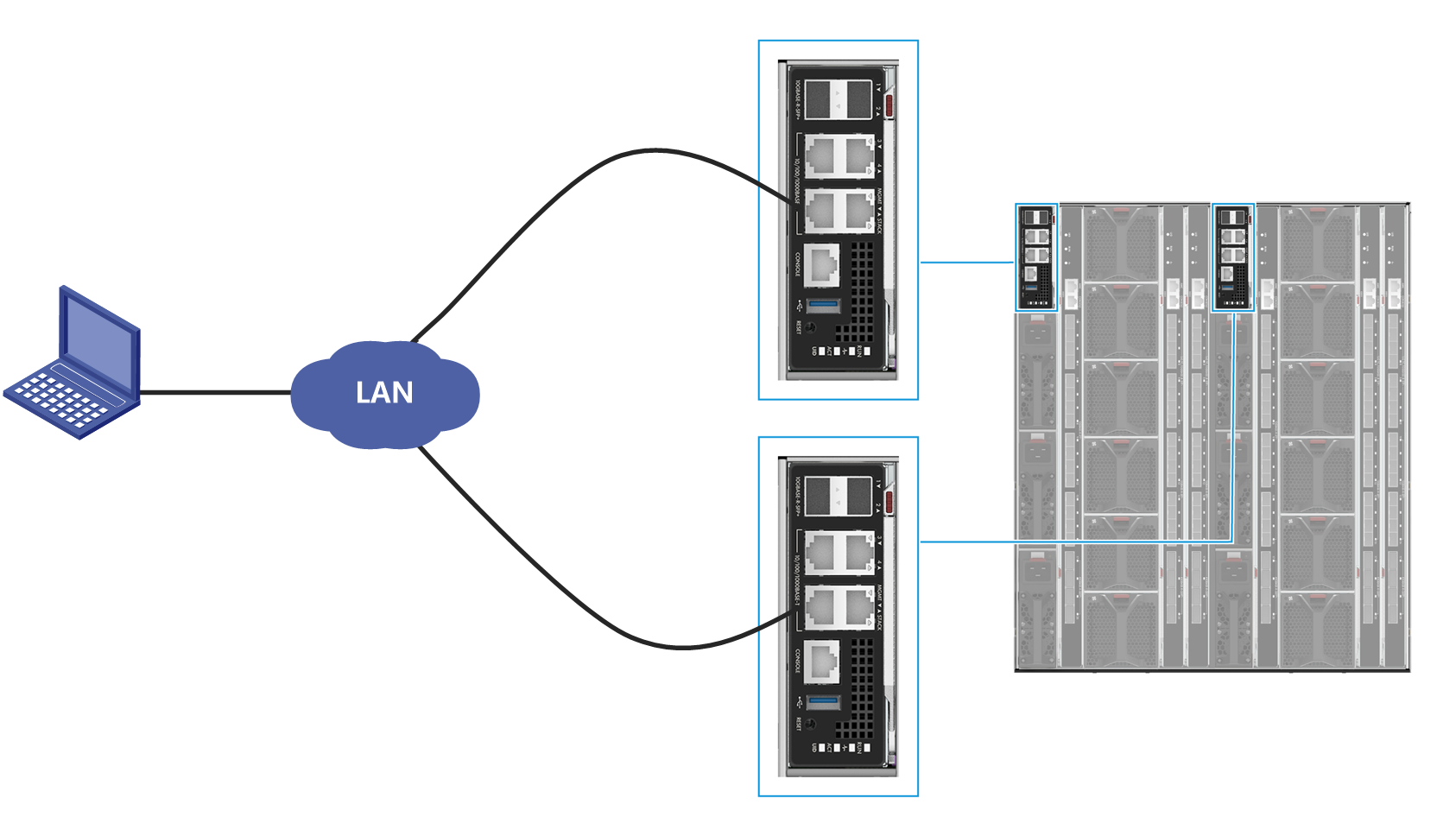
2. Connect the Ethernet port on the UniSystem client host to the MGMT port on the primary or standby OM module over the LAN, as shown in Figure 3.
Figure 3 Connecting to the OM module
3. On the UniSystem client, specify an IP address that resides on the same network segment as the UniSystem server. See Figure 2 for the default IP address of UniSystem server.
Obtain the UniSystem server IP address
|
|
IMPORTANT: After logging in to UniSystem running in an AE module by using the default IP address, change the UniSystem IP address to avoid IP address conflicts in the future. For how to change the UniSystem IP address, see "Set the IP address obtaining method for a network port and the DNS server address." |
Table 1 shows the default settings for UniSystem running in an AE module.
Table 1 Default UniSystem settings
|
Parameter |
UniSystem server location |
Parameter value |
|
Username |
N/A |
admin |
|
Password |
Password@_ |
|
|
UniSystem login IP address |
AE module slot E1 |
192.168.0.100/24 |
|
AE module slot E2 |
192.168.0.101/24 |
|
|
Non-AE environment |
System IP address of the device where UniSystem resides. |
UniSystem client requirements
Users can access UniSystem from a Web browser directly. See Table 2 for the supported Web browsers and recommended resolution.
|
Browser |
Resolution |
|
· Google Chrome 80.0 or later · Mozilla Firefox 90.0 or later |
1600 × 900 or higher |
Log in to the UniSystem Web interface
1. Enter either of the following URLs in the address bar of the browser:
¡ http://UniSystem ip address:port , where port represents the HTTP port number used by UniSystem.
¡ https://UniSystem ip address:port , where port represents the HTTPS port number used by UniSystem.
You can configure the HTTP port and HTTPS port for UniSystem in the UniSystem service startup settings. For more information, see H3C Servers UniSystem Installation Guide.
Alternatively, you can access UniSystem locally from the server where UniSystem is installed. To do so, enter http://localhost:port or http://127.0.0.1 in the address bar of the Web browser.
2. On the UniSystem login page, enter the username and password of a UniSystem user.
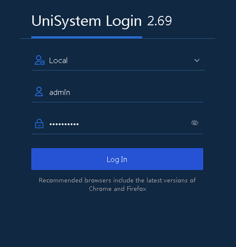
3. Click Log In.
If the username or password is incorrect, you must enter the CAPTCHA code at subsequent attempts.
Log in to UniSystem (unified O&M version)
|
|
NOTE: This chapter applies only to UniSystem installed on the U-Center platform. |
Set up the hardware environment
UniSystem of the unified O&M version is installed on the U-Center platform. For more information, see H3C U-Center 2.0 Deployment Guide.
Log in to the UniSystem Web interface
1. Enter the U-Center 2.0 login address in the format of http://ip_address:port, where ip_address represents the northbound service virtual IP address and port represents the service port number configured in portal application deployment.
2. On the login page, enter the username and password. The default username is admin and the default password is Pwd@12345. If you have set the password during operating system installation, use the set password.
3. Click Log in.
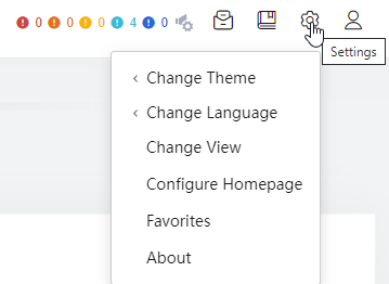
4. Click the ![]() icon at the upper
right corner. In the drop-down list, click Change View.
icon at the upper
right corner. In the drop-down list, click Change View.
5. Click the ![]() icon for
UniSystem to switch to the UniSystem view.
icon for
UniSystem to switch to the UniSystem view.
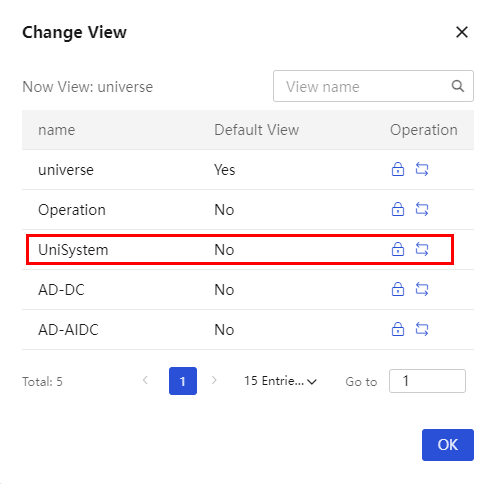
The UniSystem homepage opens, as shown in Figure 7.

UniSystem Web interface layout
The UniSystem Web interface opens, as shown in Figure 8. The UniSystem Web interface can be divided into two areas, as described in Table 3.
Figure 8 UniSystem homepage (non-unified O&M version)
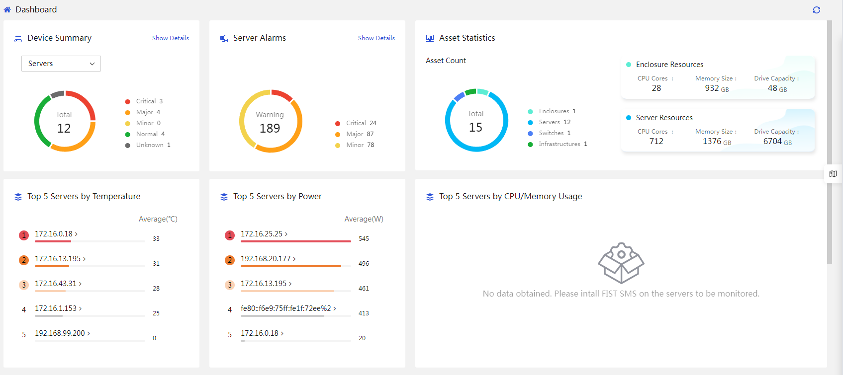
Figure 9 UniSystem homepage (unified O&M version)
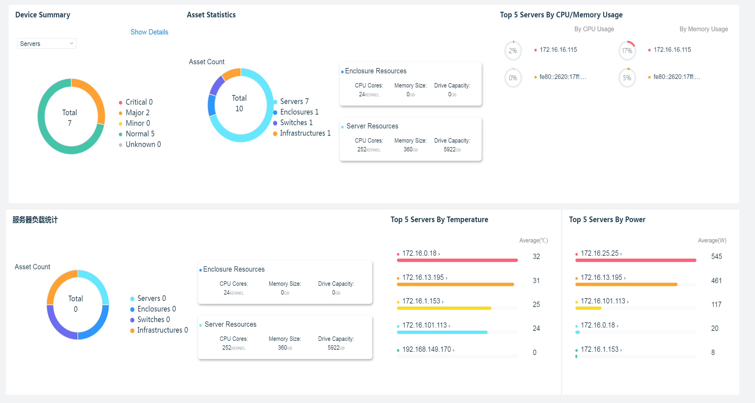
Table 3 UniSystem Web interface design
|
Area |
Description |
|
Header section |
· · · · · · · · · |
|
Work pane |
Displays operation information and function links. |
|
Operation guide (non-unified O&M version) |
Provides configuration guide for main
features and services. You can click the · Wizard—Provides step-by-step instructions for specific operations. It helps users understand and utilize the main functions or services of the product, enhancing the operational efficiency and accuracy. · Shortcuts—Provides shortcuts to access specific pages. You can enter keywords in the search box to filter guide information. |
Access by shortcut
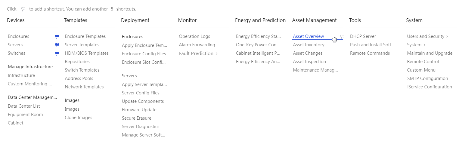
On the top navigation bar, you can use Shortcuts to access a specified menu directly. To add a
menu to Shortcuts, click Menu
and then click ![]() for the menu. To remove a
menu from Shortcuts, click Menu
and then click
for the menu. To remove a
menu from Shortcuts, click Menu
and then click ![]() for the menu. You can add a
maximum of 15 menus to Shortcuts.
for the menu. You can add a
maximum of 15 menus to Shortcuts.
Figure 10 Adding menus to shortcuts
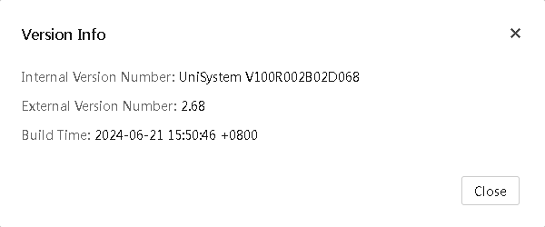
Check UniSystem version info
Click the Version Info
button ![]() in the top right corner to check the
UniSystem version information, as shown in Figure 11.
in the top right corner to check the
UniSystem version information, as shown in Figure 11.
Figure 11 UniSystem version information
Manage users
UniSystem of the unified O&M version does not support managing users.
Manage users
Both local users and LDAP users are allowed to log in to UniSystem.
Manage local users
Add a user
About this task
Perform this task to add a new user and configure the user role and the scope. For more information about user roles and domans, see "Role management" and "Scope management."
UniSystem provides a default admin user account named admin of the administrator role.
The name of a new user to be created cannot be System, which is used by the system.
Concurrent logins with the same admin user account is supported and each login is counted as a separate user. UniSystem supports a maximum of 30 concurrent online users.
Procedure
1. In the navigation pane, select Menu > System > Users and Security > User List.
The Users page displays all users.
Figure 12 Users page
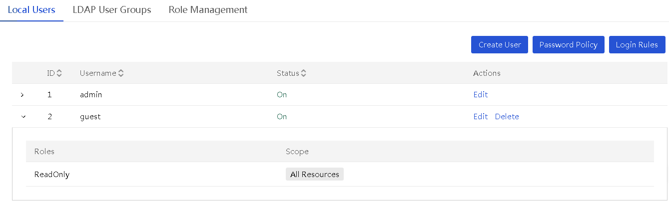
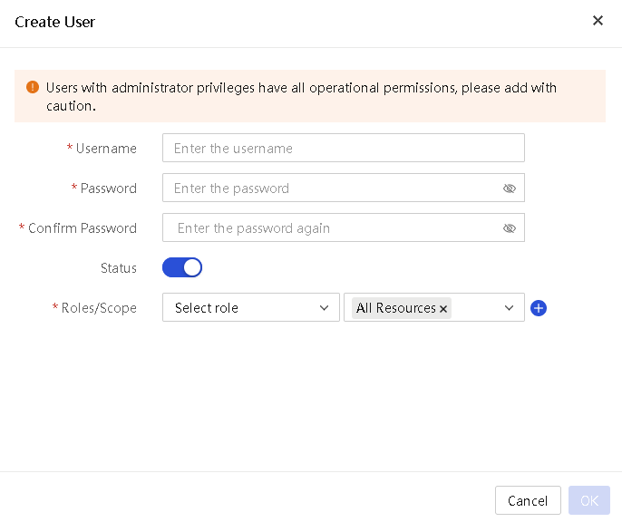
2. On the Local Users tab, click Create User. In the Create User dialog box, perform the following steps:
¡ Enter the username.
¡ Enter and confirm the password.
¡ Select a role and select the scope. The value of All Resources represents all resources in the system, indicating that the user can manage all resources and are not limited by scopes.
¡ To
add a role and scope set, click ![]() . You can add a
maximum of 15 roles for a user and bind a maximum of 20 scopes to each role.
. You can add a
maximum of 15 roles for a user and bind a maximum of 20 scopes to each role.
Figure 13 Creating a user
3. Click OK.
Edit a user
About this task
The user information that can be edited depends on the user role:
· For a user with the administrator role:
¡ If the user has permissions on all resources, the user can perform the following:
- Change the password of the default user admin.
- Change the user parameters, including the password, enabling status, roles, and scopes.
¡ If the user does not have permissions on all resources, the user can edit only the password of its own.
· For a user with a non-administrator role, the user can change only the password of its own.
Restrictions and guidelines
· The password of users must meet the all requirements in the password policy.
· Editing an online user will forcibly log out the user. The new settings take effect at the next login of the user.
Procedures
To change the password of the default user:
1. In the navigation pane, select Menu > System > Users and Security > User List.
2. On the Local Users tab, click Edit in the Actions column for default user admin.
3. In the dialog box that opens, enter the current password, and then enter and confirm the new password.
4. Click OK.
To edit a non-default user:
5. In the navigation pane, select Menu > System > Users and Security > User List.
6. On the Local Users tab, click Edit in the Actions column for a non-default user.
7. In the dialog box that opens, perform the following operations:
¡ Change the password. Select Change Password. Then, enter the current password, and enter the new password and confirm password.
¡ Change the status of the user.
¡ Select
a new role or scope from the corresponding field. To add a role and scope set,
click ![]() . To
delete a role and scope set, click
. To
delete a role and scope set, click ![]() . You can configure a maximum of 15 roles for a user and bind a
maximum of 20 scopes for a role.
. You can configure a maximum of 15 roles for a user and bind a
maximum of 20 scopes for a role.
8. Click OK.
Delete a user
About this task
Perform this task to delete a non-default user.
Restrictions and guidelines
· Only administrator users can delete users.
· Default user admin cannot be deleted.
· Deleting an online user will forcibly log out the user (including the current user that performs the deletion operation).
Procedure
1. In the navigation pane, select Menu > System > Users and Security > User List.
2. On the Local Users tab, click Delete in the Actions column for the user you want to delete.
3. In the dialog box that opens, enter the password of the current login user.
4. Click OK.
Configure a password policy
About this task
Perform this task to enhance UniSystem access security by setting rules that the passwords of user accounts (including default user admin) must follow.
Procedure
1. In the navigation pane, select Menu > System > Users and Security > User List.
2. On the Local Users tab, click Password Policy.
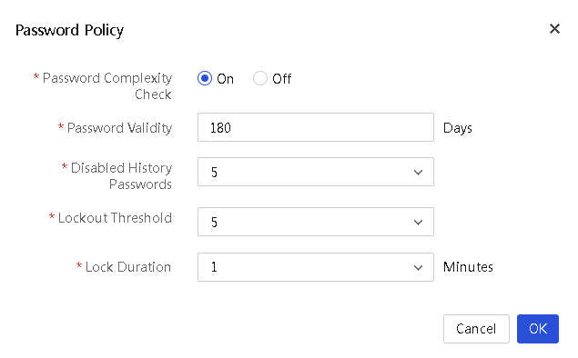
3. In the Password Policy dialog box, perform the following steps:
¡ Enable or disable the password complexity check.
¡ Set the password validity.
¡ Select the number of disabled history passwords.
¡ Select the password lockout threshold.
¡ Select the password lockout duration.
Figure 14 Password Policy dialog box
4. Click OK.
Parameters
· Password Complexity Check: Disable or enable password complexity check.
¡ If this feature is enabled, passwords must meet the following enhanced complexity requirements:
- 8 to 20 characters in length.
- Case sensitive. Valid characters are letters, digits, spaces, and the following special characters: ` ~ ! @ # $ % ^ & * ( ) _ + - = [ ] \ { } | ; ' : " , . / < > ?
- Must contain characters from at least two of the following categories: uppercase letters, lowercase letters, and digits.
- Must contain at least one space or special character.
- Must not be identical to the username or the reverse of the username.
¡ If this feature is disabled, passwords must meet the following basic complexity requirements:
- 1 to 20 characters in length.
- Case sensitive. Valid characters are letters, digits, spaces, and the following special characters: ` ~ ! @ # $ % ^ & * ( ) _ + - = [ ] \ { } | ; ' : " , . / < > ?
· Password Validity: Validity period of a password. When a password is about to expire, UniSystem prompts the user to change the password.
· Disabled History Passwords: Number of unique passwords that a user must create before a history password can be reused. For example, if you set the value to 2, a user must create two unique passwords before the user uses a history password.
· Lockout Threshold: Number of consecutive login failures that will cause a user account to be locked.
· Lock Duration: Amount of time before a locked account can be used again.
Manage login rules
About this task
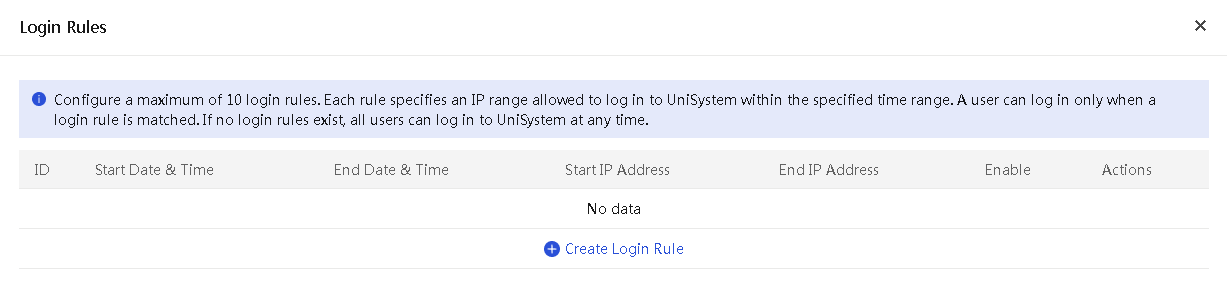
Perform this task to configure login rules to control UniSystem login. If information of a user login matches a login rule, the login is allowed. If information of a user login does not match any login rule, the login is denied. By default, no login rules are configured, and all logins are allowed.
Restrictions and guidelines
Configure login rules with caution because a user is allowed to log in to UniSystem only when a matching login rule is found.
Procedures
To create a login rule:
1. In the navigation pane, select Menu > System > Users and Security > User List.
2. On the Local Users tab, click Login Rules.
3. In the Login Rules dialog box that opens, click Create Login Rule, and then perform the following steps:
¡ Enter the start date & time and end time date & time of the time range during which users can log in to UniSystem.
¡ Enter the start IP address and end IP address.
¡ Check the box in the Enable column to activate the rule.
Figure 15 Login Rules dialog box
4. Click OK.
To edit login rules:
5. In the navigation pane, select Menu > System > Users and Security > User List.
6. On the Local Users tab, click Login Rules.
7. In the Login Rules dialog box that opens, edit the login rule settings.
8. Click OK.
To delete a login rule:
9. In the navigation pane, select Menu > System > Users and Security > User List.
10. On the Local Users tab, click Login Rules.
11. In the Login Rules dialog box that opens, click Delete in the Actions column for the login rule you want to delete.
12. Click OK.
Manage LDAP user groups
Users in the LDAP user groups that have been added to UniSystem can directly log in to UniSystem. An LDAP account cannot log in to UniSystem with pre-Windows 2000 logon name.
Before configuring an LDAP user group, configure a scope first. For more information about scopes, see "Scope management."
Add LDAP user groups
About this task
Perform this task to add LDAP user groups on an LDAP server to UniSystem. UniSystem supports a maximum of 100 user groups per LDAP server.
Before you add LDAP user groups to UniSystem, add the LDAP server hosting the LDAP user groups to UniSystem first. For more information, see "Manage LDAP."
Procedure
1. In the navigation pane, select Menu > System > Users and Security > User List.
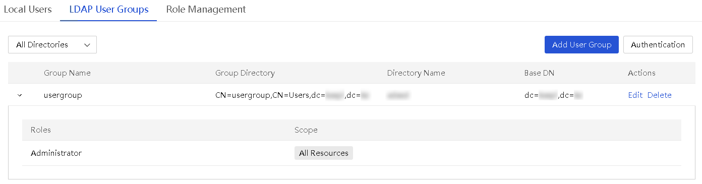
2. Click the LDAP User Groups tab.
Figure 16 LDAP user groups tab
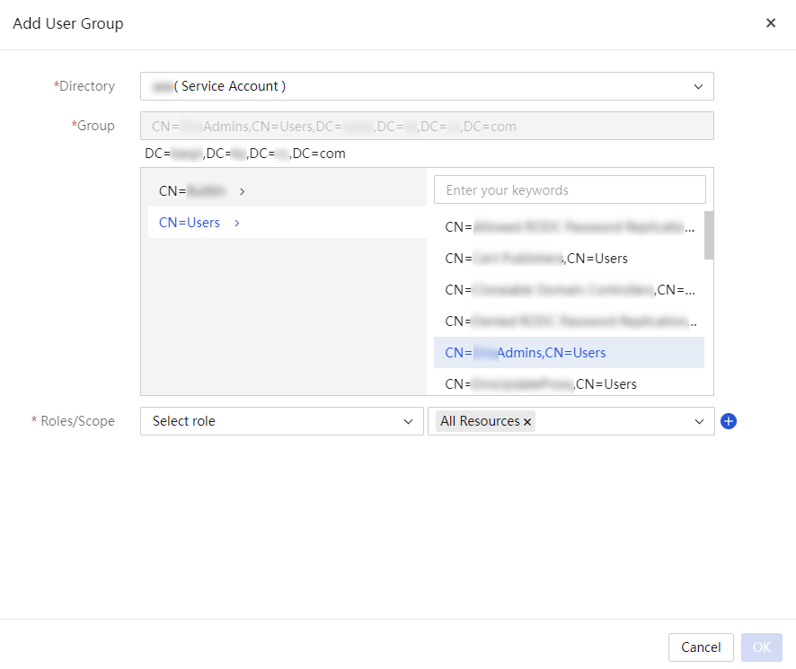
3. Click Add User Group. In the Add User Group dialog box that opens, configure the following parameters:
a. Select an LDAP server from the Directory list.
b. Select the directories of the LDAP user groups you want to add in the Group text box.
c. Select a role and a scope from the
corresponding field. To add a role and scope set, click ![]() . To
delete a role and scope set, click
. To
delete a role and scope set, click ![]() . You can
configure a maximum of 15 roles for a user and bind a maximum of 20 scopes for
a role.
. You can
configure a maximum of 15 roles for a user and bind a maximum of 20 scopes for
a role.
Figure 17 Add user group dialog box
4. Click OK.
Edit LDAP user groups
1. In the navigation pane, select Menu > System > Users and Security > User List.
2. Click the LDAP User Groups tab.
3. Click the Edit icon in the Actions column for the target LDAP user group.
4. In the Edit User Group dialog box that opens, edit the user group settings and click OK.
Delete LDAP user groups
1. In the navigation pane, select Menu > System > Users and Security > User List.
2. Click the LDAP User Groups tab.
3. Click the Delete icon in the Actions column for the target LDAP user group.
4. In the confirmation dialog box that opens, click OK.
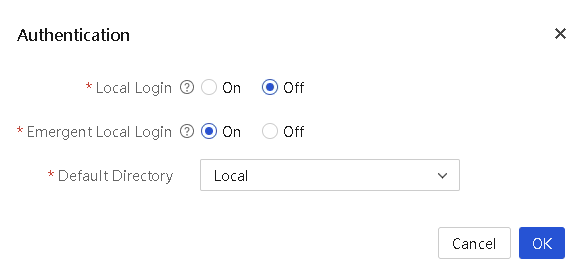
Configure user authentication
The authentication feature allows administrators to control local users' access to system resources, ensuring only authorized users can log in and access resources, effectively protecting system security. Additionally, the emergency local login feature provides special access in urgent situations for emergency operations or troubleshooting.
Procedure
1. In the navigation pane, select Menu > System > Users and Security > User List.
2. Click the LDAP User Groups tab.
3. Click Authentication. In the dialog box that opens, configure user authentication as follows:
¡ Enable or disable local login.
¡ Enable or disable emergency local login. This field is available when local login is disabled.
¡ Set the default directory.
4. Click OK.
Figure 18 User authentication
Parameters
· Local Login: Enable or disable local login.
· Emergency Local Login: Enable or disable emergency local login. This field is available when local login is disabled. With this feature enabled, only the system default user named admin can perform local login. With this feature disabled, all local user logins are prohibited.
· Default Directory: Select the default login directory. By default, the local directory is used. When both local login and emergency local login are disabled, you cannot select a local directory. You can select an LDAP server added to the system as the default directory. For more information about LDAP server configuration, see "Manage LDAP."
Restrictions and guidelines
After local login is disabled, you can perform emergency login with the admin account. Disabling emergency local login might prevent anyone from accessing the device if the directory service cannot be accessed. Perform this operation with caution to avoid unnecessary access restrictions and security risks.
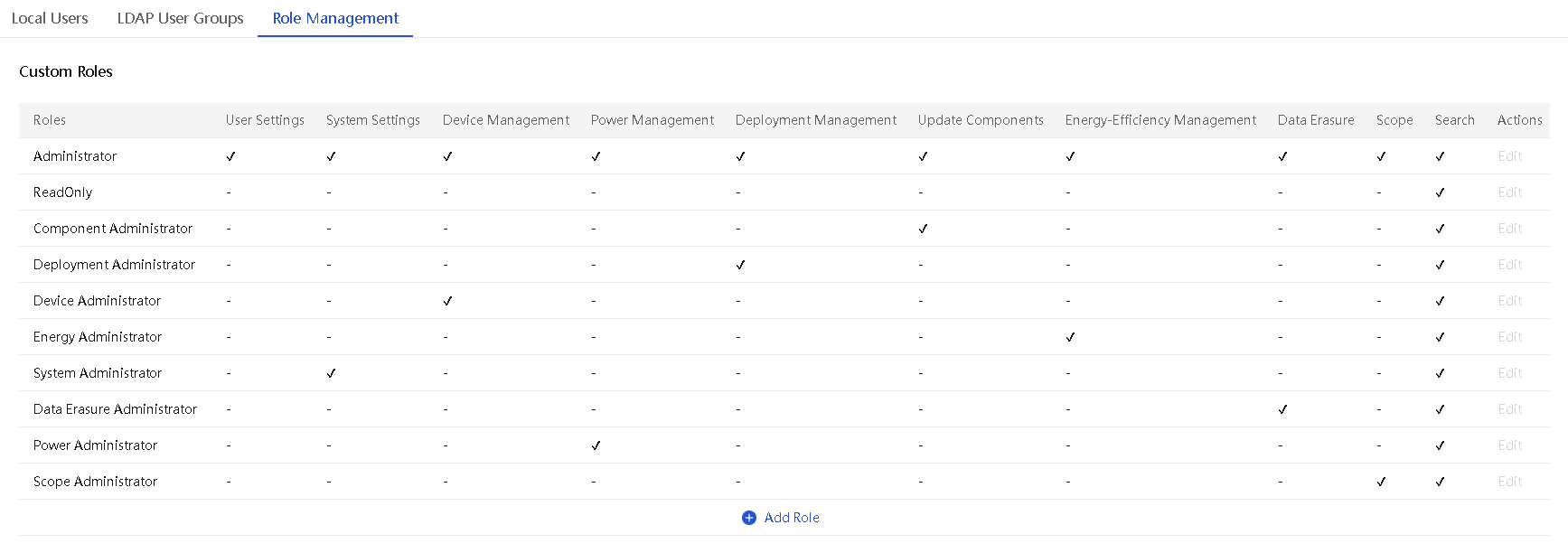
Role management
UniSystem provides the following default roles: Administrator, ReadOnly, Component Administrator, Deployment Administrator, Device Administrator, Energy Administrator, System Administrator, Data Erasure Administrator, Power Administrator, and Scope Administrator.
Figure 19 Role management

Additionally, UniSystem supports custom roles, including role names and permission modules. The descriptions of each permission module are shown in the table below.
|
|
NOTE: · The features supported by UniSystem might vary in different environments. Refer to the actual interface display for specific differences. · Menus displayed on the UniSystem Web interface depend on the user role and permissions. |
Table 4 Permission module description
|
Permission module |
Permission details |
|
User configuration |
User management, LDAP management, and online users |
|
System settings |
Network settings, proxy settings, time settings, maintenance and updates, login security, remote support, cluster management, custom menu, system interfacing |
|
Device management |
Chassis, server, switch, infrastructure, custom monitoring template, data center, equipment room, cabinet, asset summary, asset inventory, asset changes, asset inspection, maintenance management, event logs, alarm center, alarm configuration, and drive prediction |
|
Perform power operations |
Power management operations on all incorporated devices |
|
Deployment management |
Chassis configuration template, chassis configuration template application, server configuration template, server configuration template application, HDM/BIOS configuration template, switch configuration template, chassis configuration file, chassis slot configuration file, server configuration file, address pool, network template, image cloning, diskless boot, DHCP server, software push installation, PXE, image management (excluding synchronization to repositories), server diagnostics, and server software license management |
|
Component update |
REPO, components update, firmware update, and image management |
|
Energy efficiency management |
Energy efficiency statistics, one-click emergency power consumption, cabinet intelligent power management, and energy efficiency analysis |
|
Data erasing |
Secure erasure |
|
Scope |
Scope |
|
Search |
View permissions for all system pages, audit logs (view, reset, and export), own password changing, and menu (shortcut adding) |
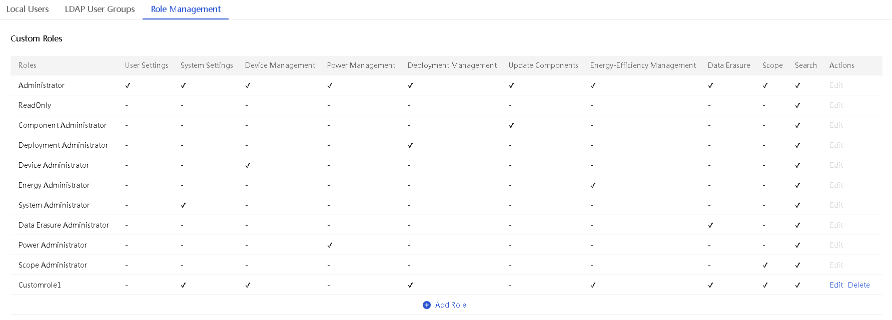
Add a role
UniSystem supports adding up to 15 roles, including the default role. Only users with the administrator role can configure roles.
Procedure
1. In the navigation pane, select Menu > System > Users and Security > User List.
2. Click the Role Management tab.
3. Click Add Role. In the dialog box that opens, enter the name of the role and select the permissions.
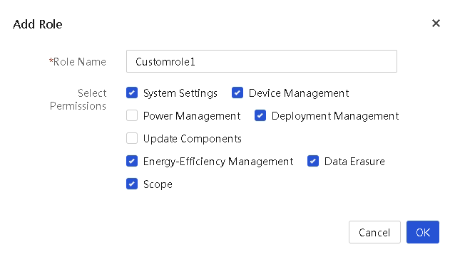
4. Click OK.
Parameters
· Role Name: Name of the role to create, a case-sensitive string of 1 to 32 characters. Only letters, digits, dots (.), hyphens (-), underscores (_), and at signs (@) are supported. The string cannot start or end with a space, and cannot be null.
· Select Permissions: Select permission modules, including system settings, device management, power management, deployment management, component updates, energy efficiency management, data erasure, and scopes.
Edit a role
Perform this task to edit a created role. Only users with the administrator role can edit a role.
Restrictions and guidelines
· You cannot edit the default role.
· If the role has a bound user and the user is in a session, the system will prompt that the editing operation fails.
Procedure
1. In the navigation pane, select Menu > System > Users and Security > User List.
2. Click the Role Management tab.
3. Click Edit in the Actions column for the target role. In the dialog box that opens, enter the name of the role and select the permissions.
4. Click OK.
Delete a role
Perform this task to delete a created role. Only users with the administrator role can delete roles.
Restrictions and guidelines
You cannot delete the default role or roles that are bound to users.
Procedure
1. In the navigation pane, select Menu > System > Users and Security > User List.
2. Click the Role Management tab.
3. Click Delete in the Actions column for the target role. In the confirmation dialog box that opens, click OK.
View online user information
About this task
Perform this task to view information about all online users.
Restrictions and guidelines
If a user exits UniSystem without clicking Log Out on the UniSystem Web interface, the user will not be removed from the online user list until the timeout timer expires.
Procedure
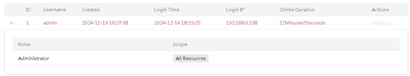
1. In the navigation pane, select Menu > System > Users and Security > Online Users.
The online user list displays all online users in UniSystem.
2. View information about the online users.
3. To kick out an online user, click the Kick Out link in the Actions column for the user. Only users with the administrative role can kick out online users.
4. Select the ![]() icon for the
target user to view the information about the role and scope for the user.
icon for the
target user to view the information about the role and scope for the user.
Figure 23 Online Users page
Parameters
· Username: Name of an online user.
· Created: Time when the user was created.
· Login Time: Time when the user logged in to UniSystem most recently.
· Login IP: IP address used by the user to log in to UniSystem.
· Online Duration: Length of time elapsed since the user logged in to UniSystem.
· Roles: Role of the user.
· Scope: Management scope of the user.
Manage devices
UniSystem offers comprehensive and flexible device management capabilities, covering integrated management from enclosures, servers, and switches to the entire infrastructure and data center. This enables efficient coordination and management of various types of equipment.
· Unified management
Centralized management of various devices through a unified platform simplifies the operation process and enhances overall management efficiency.
· Refined scope management
Support multi-dimensional scope division based on departments or regions, categorizing devices as resources within those scopes. Users can access and manage only the authorized resources according to their assigned roles and scopes, enhancing security and resource control.
|
|
NOTE: · To manage devices based on scopes, you must first configure the scopes. For more information, see "Scope management." · The value of All Resources represents all resources in the system, indicating that the user can manage all resources and are not limited by scopes. If the current user can manage all resources, the scople configuration is optional. |
Manage enclosures
From the Enclosure List menu, you can manage enclosures and the blade servers and other modules in the enclosures.
General restrictions and guidelines
UniSystem communicates with the OM module of an enclosure through HTTP to manage the enclosure. For UniSystem to manage an enclosure correctly, do not disable the HTTP service on the OM Web interface.
Manage enclosures
As shown in Figure 24, an AE module is shipped with UniSystem pre-installed. UniSystem provides centralized management of data center devices including the local enclosure where the AE module resides, remote enclosures, rack servers, and switches. You can access UniSystem on the AE module simply by connecting to the management port of the OM module, which is connected to the AE module by default within the enclosure.
Figure 24 UniSystem management enclosure network diagram
Add an enclosure
About this task
Perform this task to add an enclosure to UniSystem. If an enclosure to be added has enclosures cascaded, UniSystem will automatically add the cascaded enclosures.
If UniSystem is running in an AE module, the enclosure where the AE module resides will be added to UniSystem automatically and cannot be deleted.
Adding an enclosure to UniSystem automatically adds all blade servers installed in the enclosure to UniSystem. You can view the blade servers on the Menu > Devices > Servers.
Restrictions and guidelines
If the OM management address of the enclosure to be added is on a different subnet than UniSystem, you must configure the network settings to enable UniSystem to communicate with the enclosure. For more information, see "Set the IP address obtaining method for a network port and the DNS server address."
Procedure
1. In the navigation pane, select Menu > Devices > Enclosures.
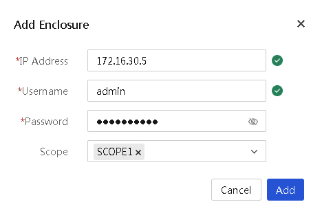
2. Click Add Enclosure.
3. In the dialog box that opens, perform the following tasks to add an enclosure:
a. Enter the IP address of the management port of the enclosure.
b. Enter the username used to log in to the OM module of the enclosure. Make sure the specified user has the administrator role.
c. Enter the password used to log in to the OM module of the enclosure.
d. Select the scope of the enclosure.
4. Click OK.
Figure 25 Adding an enclosure
Delete an enclosure
About this task
Perform this task to delete an enclosure.
Restrictions and guidelines
If UniSystem is running in an AE module, the enclosure where the AE module resides cannot be deleted.
Procedure
1. In the navigation pane, select Menu > Devices > Enclosures.
2. Click Delete in the Actions column for the enclosure to be deleted.
3. In the confirmation dialog box that opens, click OK.
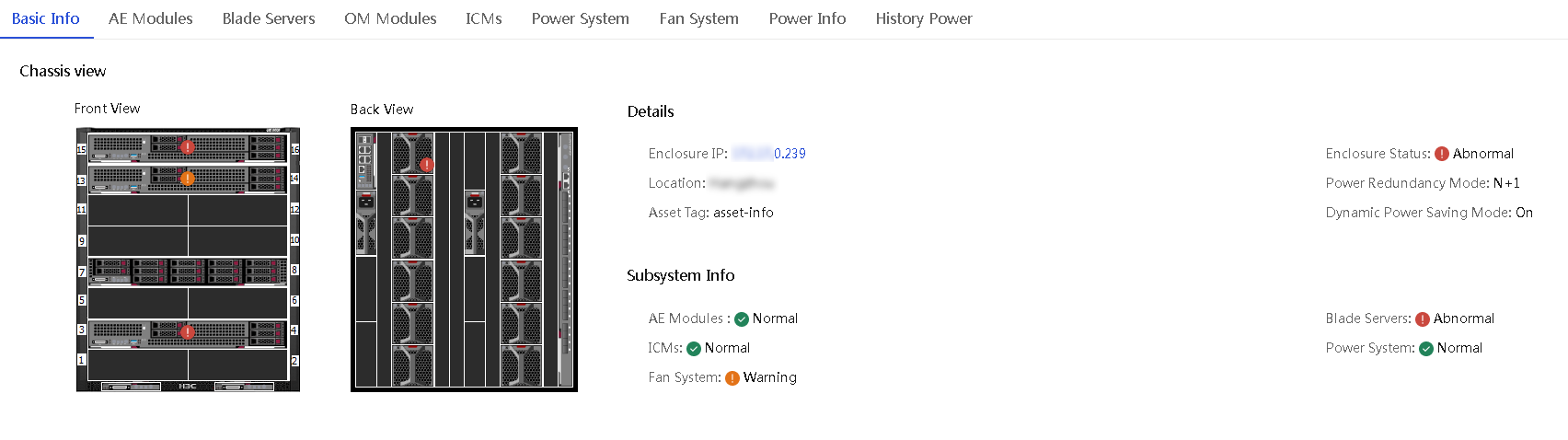
View enclosure information
About this task
Perform this task to access the enclosure list page to view information about enclosures managed by UniSystem. From the page, you can also drill down to view the detailed information of individual enclosures.
Procedure
1. In the navigation pane, select Menu > Devices > Enclosures. The Enclosures page displays information about all enclosures.
Figure 26 Enclosures page
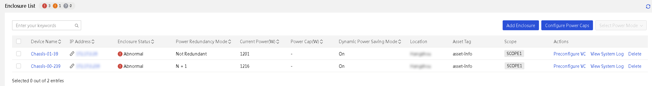
2. Click the name of an enclosure to open the enclosure details page.
Figure 27 Enclosure Details
Configure power caps for enclosures
About this task
Perform this task to set the power caps for enclosures, either statically or dynamically depending on the configuration method you select. The power cap set for an enclosure determines the maximum amount of power that can be consumed by the enclosure and all the devices installed in it.
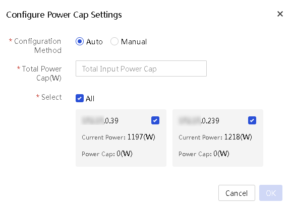
Supported power cap configuration methods are:
· Auto—Configure UniSystem to dynamically allocate power caps to selected enclosures in bulk. In this mode, select the target enclosures, set the total power cap value that can be allocated to these enclosures, and click OK. Then, UniSystem automatically allocates a power cap to each enclosure in proportion to the enclosure's share of the total power consumed by all the selected enclosures. That is, the higher the current power of an enclosure, the higher the power cap allocated to it. If the power cap calculated for an enclosure exceeds the limit (18000 W), the enclosure's power cap will be set to 18000 W.
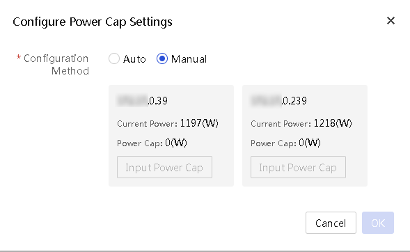
· Manual—Manually specify the power caps for individual enclosures.
Restrictions and guidelines
· The power cap of an enclosure is in the range of 2500 W to 18000 W.
· To dynamically set the power caps for N enclosures from a total available power cap value, specify the total aggregate power cap in the range of 2500 W*N to 18000W*N.
Procedure
1. In the navigation pane, select Menu > Devices > Enclosures.
2. Click Configure Power Caps.
3. Select a configuration method, Manual or Auto.
4. To have UniSystem dynamically allocate power caps to enclosures:
a. Select Auto for Configuration Method.
b. Select the target enclosures. By default, all enclosures are selected.
c. In the Total Power Cap (W) field, specify the total power cap value that can be allocated to the selected enclosures.
Figure 28 Configuring UniSystem to dynamically allocate power caps to selected enclosures
5. To set power caps for individual enclosures manually:
a. Select Manual for Configuration Method.
b. Set the power cap value for each enclosure.
Figure 29 Manually setting the power caps for enclosures
6. Click OK.
Set the power mode for enclosures
About this task
Perform this task to configure the power settings for an enclosure.
The power supply system of an enclosure can contain up to six hot-swappable power supplies. Install power supplies and configure the power redundancy mode according to the enclosure's power requirements, which vary depending on the number and type of devices installed in the enclosure.
UniSystem supports the following power management features:
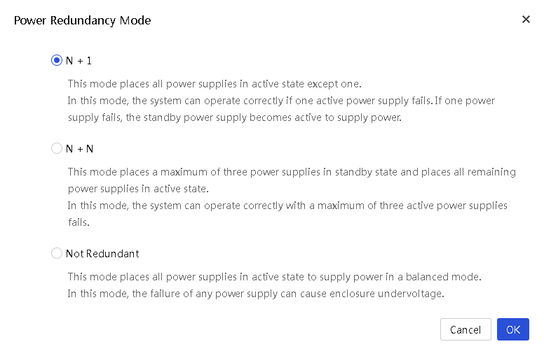
· Power redundancy mode—Protects an enclosure from power supply failures.
UniSystem supports both the N+1 and N+N redundancy modes. In the event of one or more power supply failures, the redundant power supplies take over the load to prevent the system from powering off. The system powers off only when the surviving power supplies do not have enough power to meet the system's power requirements. If no redundant power supply is available (as is the case with the No Redundancy mode), the system might power off when one power supply fails.
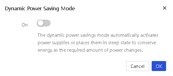
· Dynamic power saving mode—Automatically places unused power supplies in standby mode to increase enclosure power supply efficiency, thereby minimizing enclosure power consumption during lower power demand. Increased power demands automatically return standby power supplies to full performance.
For example, assume that an enclosure has six power supplies installed, is configured to work in N+1 power redundancy mode, and requires two active power supplies to supply the current power.
¡ If the dynamic power saving mode is enabled, only three power supplies share in delivering the enclosure power load, with one being the redundant power supply. The remaining three power supplies will be placed in standby mode.
¡ If the dynamic power saving mode is disabled, all of the six power supplies share the power load.
Restrictions and guidelines
· Make sure all power supplies installed in the enclosure are of the same model.
Table 5 provides information about supported power supplies.
Table 5 Supported power supplies
|
Type |
Model |
Rated input voltage range |
Maximum rated output power |
|
3000 W AC power supply |
PSR3000-12A |
100 VAC to 240 VAC |
3000 W |
· When setting the power redundancy mode for an enclosure, make sure the enclosure has the correct number of power supplies installed in the correct locations.
Table 6 shows the recommended power settings for an enclosure with 3000 W AC power supplies. If the number of power supplies exceeds the recommended number, enable the dynamic power saving mode to reduce power consumption.
Table 6 Recommended power settings for an enclosure with 3000 W AC power supplies
|
Max power that can be supplied |
Power redundancy mode |
Number of power supplies installed |
Recommended power supply bays |
|
3000 W |
No Redundancy |
1 |
PSU_1 |
|
6000 W |
No Redundancy |
2 |
PSU_1, PSU_2 |
|
9000 W |
No Redundancy |
3 |
PSU_1, PSU_2, PSU_3 |
|
12000 W |
No redundancy |
4 |
PSU_1, PSU_2, PSU_3, PSU_4 |
|
15000 W |
No Redundancy |
5 |
PSU_1, PSU_2, PSU_3, PSU_4, PSU_5 |
|
18000 W |
No Redundancy |
6 |
PSU_1, PSU_2, PSU_3, PSU_4, PSU_5, PSU_6 |
|
3000 W |
1+1 redundancy |
2 |
PSU_1, PSU_2 |
|
6000 W |
2+1 redundancy |
3 |
PSU_1, PSU_2, PSU_3 |
|
9000 W |
3+1 redundancy |
4 |
PSU_1, PSU_2, PSU_3, PSU_4 |
|
12000 W |
4+1 redundancy |
5 |
PSU_1, PSU_2, PSU_3, PSU_4, PSU_5 |
|
15000 W |
5+1 redundancy |
6 |
PSU_1, PSU_2, PSU_3, PSU_4, PSU_5, PSU_6 |
|
6000 W |
2+2 redundancy |
4 |
PSU_1, PSU_2, PSU_3, PSU_4 |
|
9000 W |
3+3 redundancy |
6 |
PSU_1, PSU_2, PSU_3, PSU_4, PSU_5, PSU_6 |
Procedure
2. In the navigation pane, select Menu > Devices > Enclosures.
3. To set the power redundancy mode for an enclosure, select the enclosure, click Select Power Mode, and then select Power Redundancy Mode from the menu. In the dialog box that opens, select a power redundancy mode as needed, and then click OK.
Figure 30 Setting power redundancy mode
4. To enable or disable the dynamic power saving mode for an enclosure, select the enclosure, click Select Power Mode, and then select Dynamic Power Saving Mode from the menu. In the dialog box that opens, enable or disable the dynamic power saving mode as needed, and then click OK.
Figure 31 Enabling or disabling the dynamic power saving mode
Manage OM modules
About this task
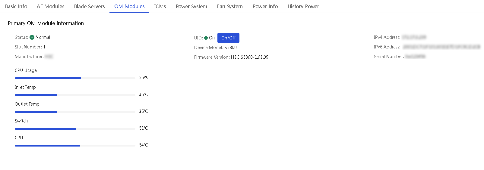
As the management core of an enclosure, the OM module is interconnected with all other modules inside the enclosure through the enclosure's backplane to provide centralized management and monitoring.
The OM Modules tab of an enclosure details page displays information about the primary and secondary OM modules in the enclosure. From the tab, you can turn on or turn off the UID LED for the OM modules. Turning on the UID LED helps locate the enclosure, especially in a high-density equipment room.
Procedure
1. In the navigation pane, select Menu > Devices > Enclosures.
2. Click the name of an enclosure.
3. Click the OM Modules tab.
The tab displays information about the primary and secondary OM modules in the enclosure.
4. (Optional.) Turn on or off the UID LED as needed.
Figure 32 Viewing the OM module information of an enclosure
Manage AE modules
From the AE Modules tab of an enclosure details page, you can perform the following tasks:
· View basic and detailed information about each AE module in the enclosure.
· Turn on or turn off the UID LED for AE modules.
· Manage the virtual power for AE modules. For example, you can power on one or more selected AE modules.
· Launch a remote console to an AE module.
For the AE module where UniSystem resides, you can only view its basic information. Other functions are not supported.
Access the AE module list page
About this task
Perform this task to access the AE module list page of an enclosure.
Procedure
1. In the navigation pane, select Menu > Devices > Enclosures.
2. Click the name of an enclosure.
3. Click the AE Modules tab.
The tab lists all AE modules in the enclosure.
Figure 33 AE module list page of an enclosure
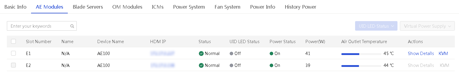
4. To change the UID LED state for one or more AE modules, select the AE modules, and then select On or Off from the UID LED Status list in the upper right corner.
5. To change the virtual power supply state for one or more AE modules, select the AE modules, and select a power option from the Virtual Power Supply list in the upper right corner. Then, click OK in the dialog box that opens.
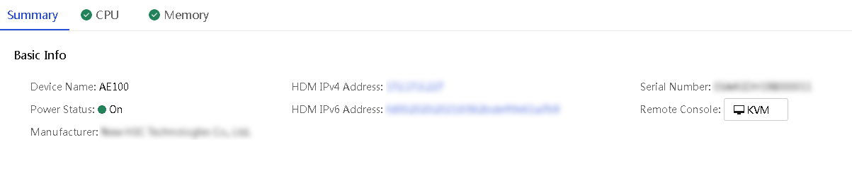
View detailed information about an AE module
About this task
Perform this task to access the details page of an AE module. The page displays information about the AE module on separate tabs, including Basic Info, CPU, and Memory.
Restrictions and guidelines
You cannot view detailed information about the local AE module where UniSystem resides.
Procedure
1. In the navigation pane, select Menu > Devices > Enclosures.
2. Click the name of an enclosure.
3. Click the AE Modules tab.
The AE module list page opens.
4. Click Show Details in the Actions column for the AE module whose detailed information you want to view.
The AE module details page opens, displaying the Summary tab by default.
5. To view the CPU information of the AE module, click the CPU tab.
6. To view the memory information of the AE module, click the Memory tab.
Figure 34 AE module details page
Launch a remote console
About this task
Perform this task to manage an AE module from the KVM remote console.
Prerequisites
Before you can launch the KVM remote console for an AE module from UniSystem, verify that the KVM service is enabled on the AE module. If the KVM service is not enabled, enable the KVM service on the Security > Access services page of the AE module's HDM Web interface.
Restrictions and guidelines
This function is not available for the local AE module where UniSystem resides.
Procedure
1. In the navigation pane, select Menu > Devices > Enclosures.
2. Click the name of an enclosure.
3. Click the AE Modules tab.
4. Click the KVM link in the Actions column for the target AE module.
5. Download the .jnlp file when prompted, and then run the file to launch the remote console window.
Manage blade servers
The blade servers in an enclosure provide compute and storage services.
From the Blade Servers tab of an enclosure details page, you can perform the following tasks:
· View basic and detailed information about the blade servers in the enclosure.
· Turn on or turn off the UID LED for blade servers.
· Manage the virtual power for blade servers. For example, you can power on or power off the blade servers.
· Set the one time boot options for blade servers
· Launch a remote console to a blade server.
Access the blade server list page of an enclosure
About this task
Perform this task to open the blade server list page of an enclosure.
Procedure
1. In the navigation pane, select Menu > Devices > Enclosures.
2. Click the name of an enclosure.
3. Click the Blade Servers tab.
The tab lists all blade servers in the enclosure.
Figure 35 Blade Server tab of an enclosure
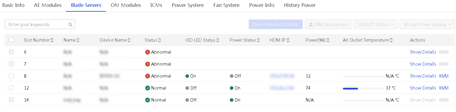
4. To change the UID LED state for one or more blade servers, select the blade servers, and then select On or Off from the UID LED Status list.
5. To change the virtual power supply state for one or more blade servers, select the blade servers, and select a power option from the Virtual Power Supply list. Then, click OK in the dialog box that opens.
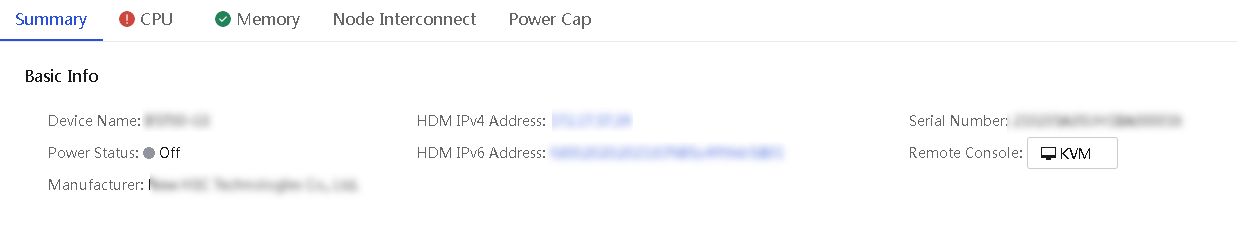
6. To view detailed information about a blade server, click the Details link in the Actions column for the server.
The page displays the summary information of the blade server by default. Click the Summary, CPU, Memory, and Node Interconnect tabs to view the CPU, memory, and mezzanine card information of the server as needed.
Figure 36 Blade server details page
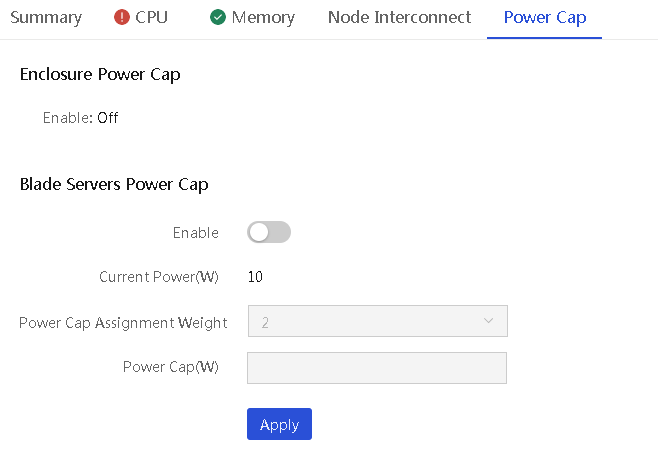
Set the power cap for a blade server
About this task
Perform this task to set the power cap or power cap assignment weight for a blade server.
To set the power cap for a blade server, you must first disable the power cap feature for the enclosure where the server resides. For more information, see "View power information."
If power cap is enabled for an enclosure, you can set the power cap assignment weight for individual blade servers installed in the enclosure. A higher weight indicates that the blade server can get a higher power cap value. The default power cap assignment weight varies by the blade server type:
· For a 2-processor compute blade server, the default value is 2.
· For a 2-processor storage blade server, the default value is 3.
· For a 4-processor compute blade server, the default value is 4.
Procedure
1. In the navigation pane, select Menu > Devices > Enclosures.
2. Click the name of an enclosure, and then click the Blade Servers tab.
3. Click Show Details in the Actions column for the blade server for which you want to set the power cap.
4. Click the Power Cap tab.
5. Set the power cap assignment weight or power cap value for the blade server:
¡ If power cap is enabled for the enclosure, set the power cap assignment weight for the blade server.
¡ If power cap is disabled for the enclosure, enable power cap for the blade server and set the power cap value for the blade server.
6. Click Apply.
Figure 37 Setting the power cap for an enclosure
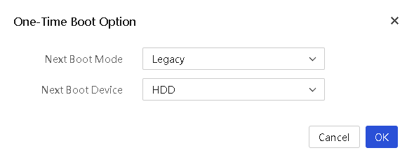
Configure boot option for the next reboot
About this task
Perform this task to specify the one-time boot mode and boot device for a server to use at the next reboot.
Procedure
1. In the navigation pane, select Menu > Devices > Enclosures.
2. Click the name of an enclosure.
3. Click the Blade Servers tab.
4. Select the target servers, and then click One-Time Boot Option.
5. Configure the following parameters as needed:
¡ Next Boot Mode: Select the boot mode for the next reboot. Options include Legacy and UEFI (the default). To use the boot mode set in BIOS for the next reboot, leave this field empty.
¡ Next Boot Device: Select the boot device for the next reboot. Options include HDD, PXE, BIOS, and CD/DVD. To use the BIOS settings at the next reboot, leave this field empty.
6. Click OK.
Figure 38 Setting the one-time boot option
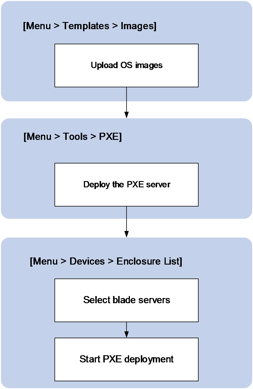
Install operating systems by using PXE
About this task
Perform this task to bulk install operating systems on blade servers by using PXE.
Before PXE deployment, upload the OS image to the Menu > Templates > Images list and enable the PXE server. For more information, see "Manage images" and "Configure PXE deployment."
Figure 39 shows the PXE deployment procedure.
Figure 39 PXE deployment procedure
Restrictions and guidelines
Make sure the IP addresses in the DHCP IP pool do not conflict with existing IP addresses on the network.
Make sure the BIOS boot mode used during the PXE installation of the operating system is the same as the BIOS boot mode used for subsequent access to the operating system. Otherwise subsequent access to the operating system might fail.
The default root password for the Linux OS installed by this feature is 123456.
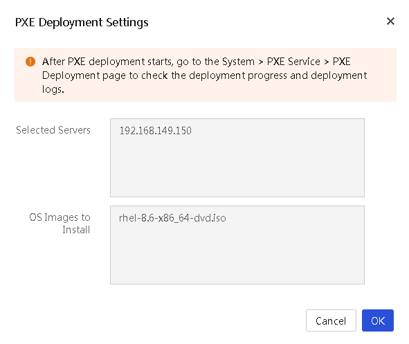
Procedure
1. In the navigation pane, select Menu > Devices > Enclosures.
2. Click the name of an enclosure.
3. Click the Blade Servers tab.
4. Select the target servers, and then click PXE Deployment.
5. Configure the PXE installation parameters and complete the OS installation on the selected servers.
Figure 40 Install operating systems by using PXE
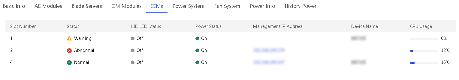
View interconnect modules
About this task
Perform this task to view the interconnect modules in an enclosure.
Interconnect modules connect devices within an enclosure so they can communicate with each other. They also provide external data interfaces for connecting to external devices.
Procedure
1. In the navigation pane, select Menu > Devices > Enclosures.
2. Click the name of an enclosure.
3. Click the ICMs tab.
Figure 41 ICMs tab
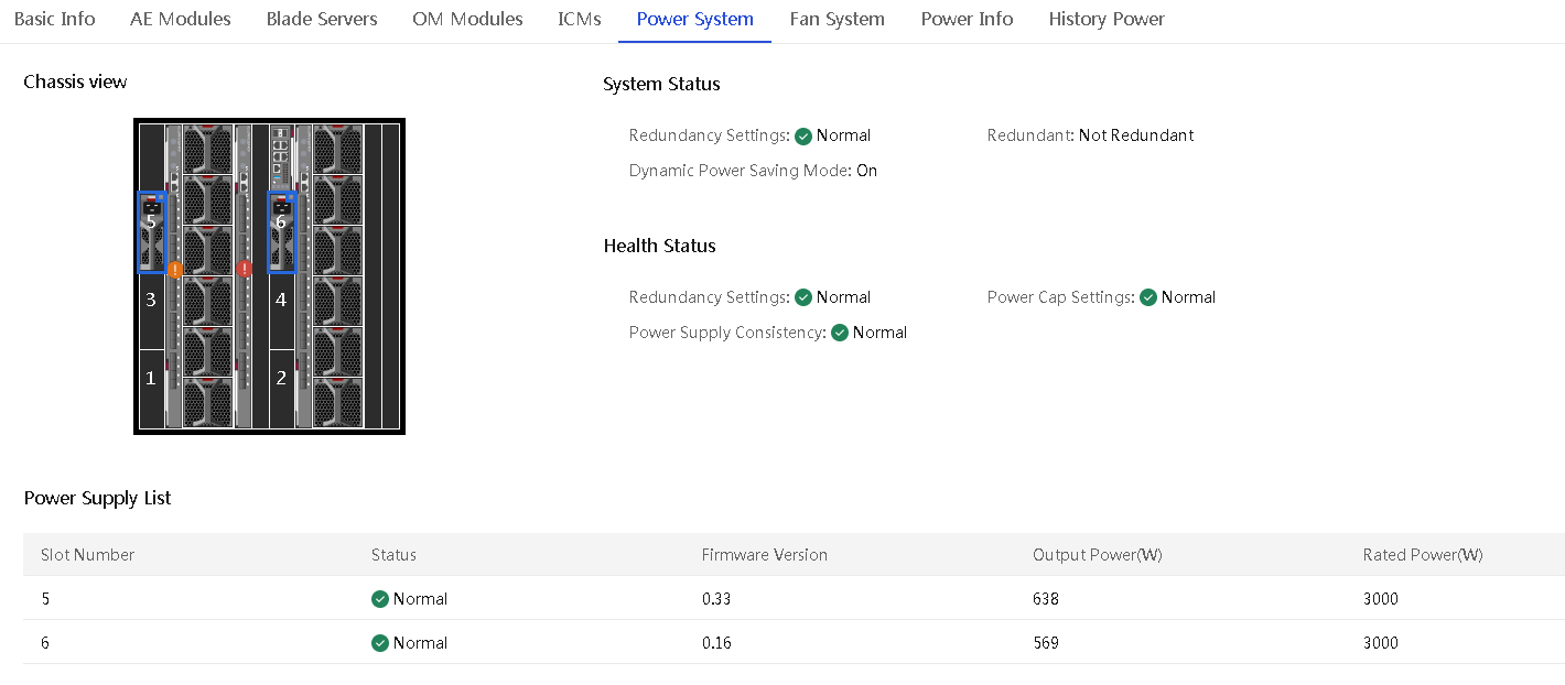
View power system information
About this task
Perform this task to view the power supply information of an enclosure, including the power system information, health status, and power supply list.
Procedure
1. In the navigation pane, select Menu > Devices > Enclosures.
2. Click the name of an enclosure.
3. Click the Power System tab.
The tab displays information about power supplies in the enclosure.
Figure 42 Power System tab
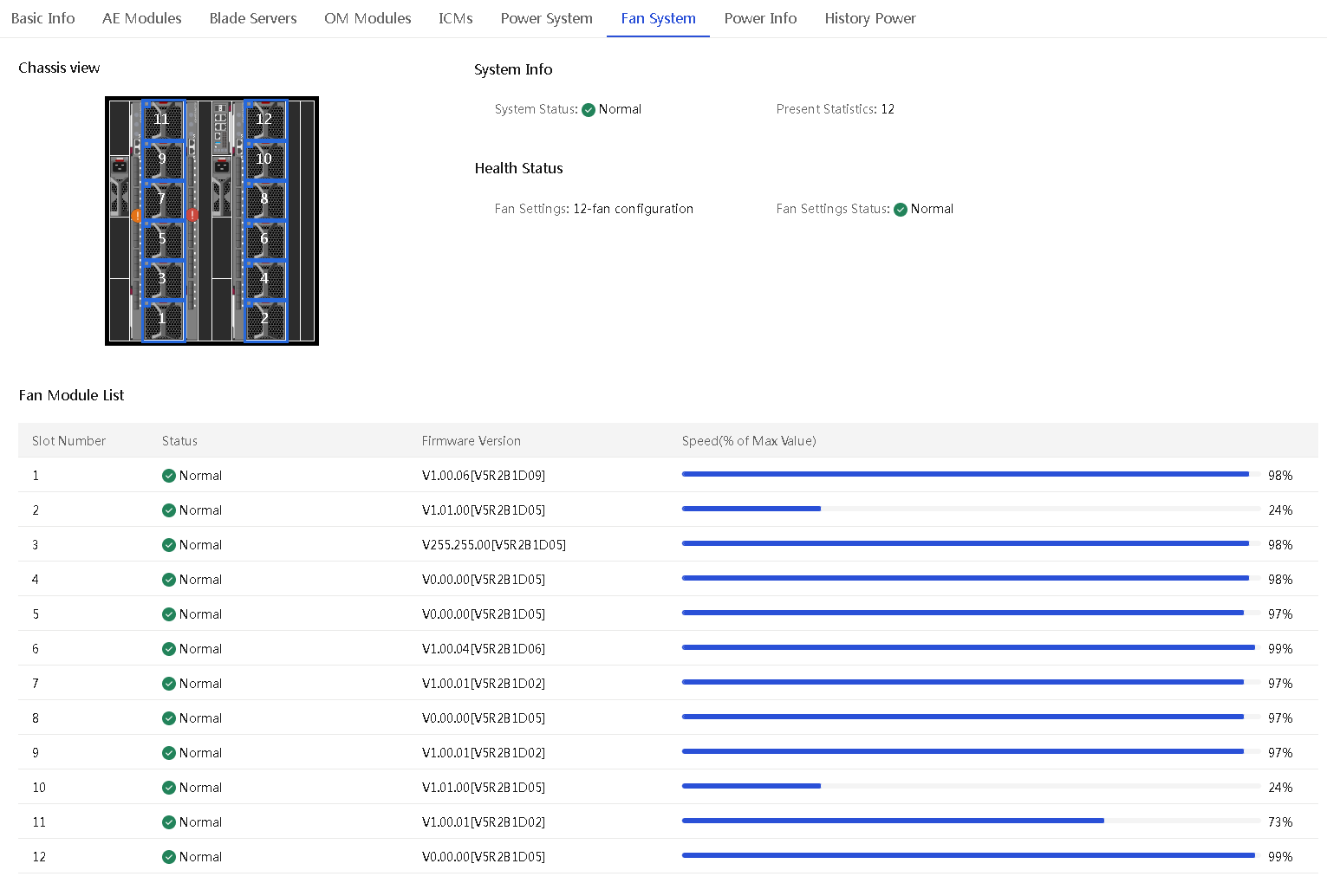
View fan system information
About this task
Perform this task to view basic information about fans, including the fan system information, health status, and fan module list.
The fan system supports a maximum of 12 fans in an enclosure, which provide N+1 redundancy. If one fan fails, the remaining fans keep running at the full speed to ensure heat dissipation, and the fan system remains in normal state.
The requirement on fan configuration depends on the installation situation of blade servers in an enclosure. When you install blade servers in an enclosure, follow these restrictions and guidelines:
· Install blade servers in the enclosure from left to right and from bottom to top.
· If both half-width and full-width blade servers are to be installed, install half-width blade servers first.
Based on the installation situation of blade servers in an enclosure, use one of the following fan configurations:
· 8-fan configuration: If area 3 of the enclosure does not have blade servers installed, you must install a minimum of 8 fans in the enclosure. Make sure fan bays 1 through 8 are installed with fans.
· 12-fan configuration: If area 3 of the enclosure has blade servers installed, you must install 12 fans in the enclosure.
Figure 43 Blade server installation areas
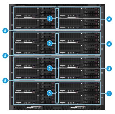
|
(1) to (4) Blade server installation areas |
|
(5) Fixed device bay shelf |
|
(6) Removable device bay divider |
Figure 44 Fan bays
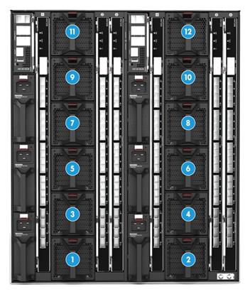
|
(1) to (12) Fan bays |
Procedure
1. In the navigation pane, select Menu > Devices > Enclosures.
2. Click the name of an enclosure.
3. Click the Fan System tab.
The tab displays information about fans in the enclosure.
Figure 45 Fan System tab
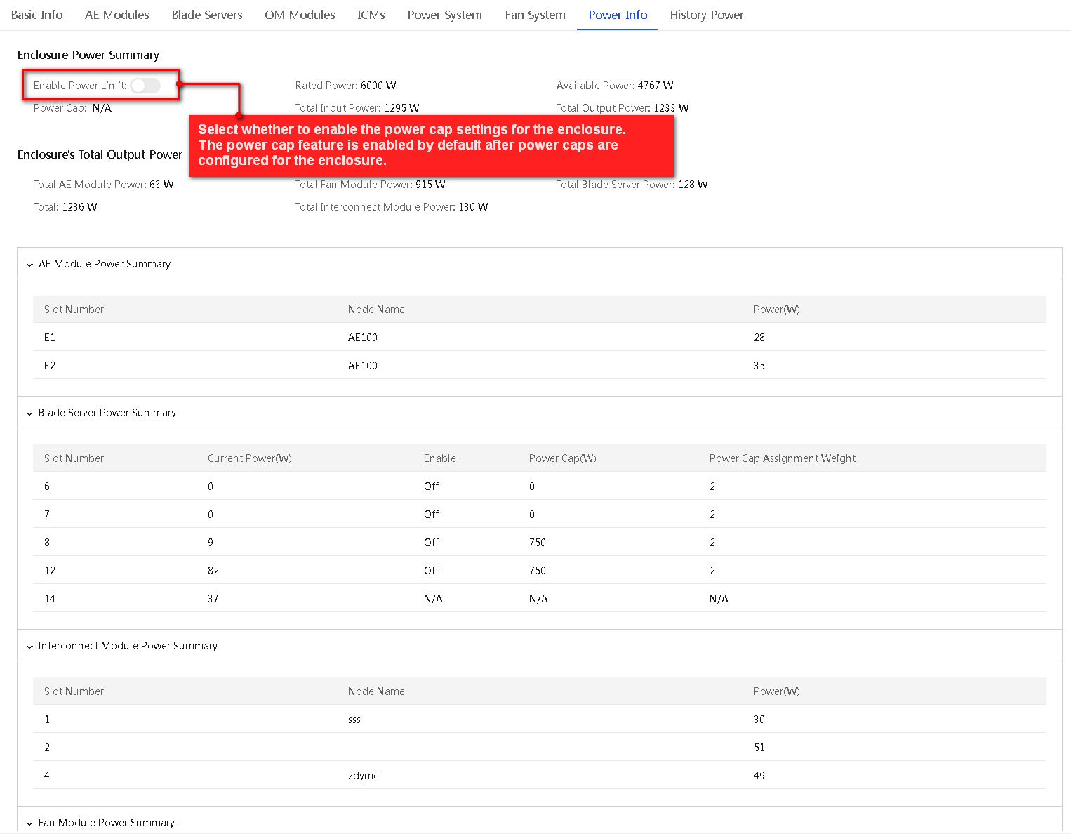
View power information
Perform this task to view the enclosure's power summary information, the enclosure's total output power information, and the power summary information of AE modules, blade servers, interconnect modules, and fans.
Procedure
1. In the navigation pane, select Menu > Devices > Enclosures.
2. Click the name of an enclosure.
3. Click the Power Info tab.
The tab displays information about power information of the enclosure.
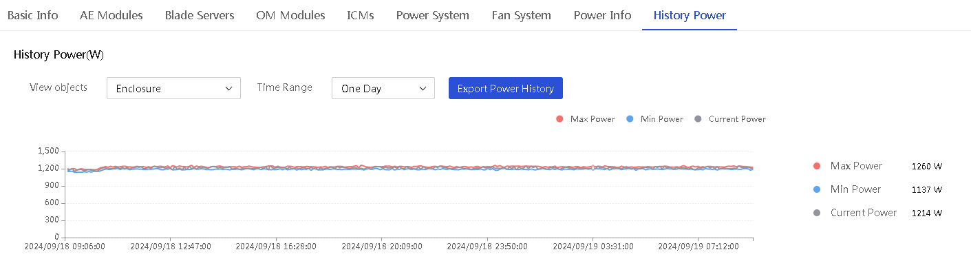
View power history
About this task
Perform this task to view and export power history data of an enclosure or blade servers in the enclosure. You can view the last week's data aggregated at 1-hour intervals, or view the last day's data aggregated at 5-minute intervals.
Procedure
1. In the navigation pane, select Menu > Devices > Enclosures.
2. Click the name of an enclosure.
3. Click the History Power tab.
The tab page displays a power history chart and power history statistics of the enclosure.
4. To display power history statistics of an object within a time range, select the object from the View Objects list and the time range from the Time Range list.
5. Hover over a point on the power history chart to view the power statistics of the corresponding time.
6. To export power history statistics, click Export Power History.
Figure 47 Power History tab
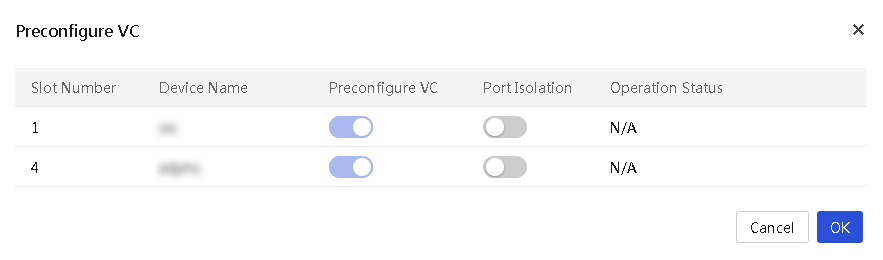
Preconfigure VC
About this task
Restrictions and guidelines
This feature becomes unavailable if an interconnect module is configured with IRF.
To use the VC preconfiguration function, make sure the firmware version of the OM module is between UN_BLADE-OM-1.02.08 and 1.02.12.
Before VC preconfiguration, make sure the remaining storage space of the OM module and interconnect module is enough to avoid configuration failure.
Procedure
1. In the navigation pane, select Menu > Devices > Enclosures.
2. Click Preconfigure VC in the Actions column.
3. In the dialog box that opens as shown in Figure 48, preconfigure VC and click OK.
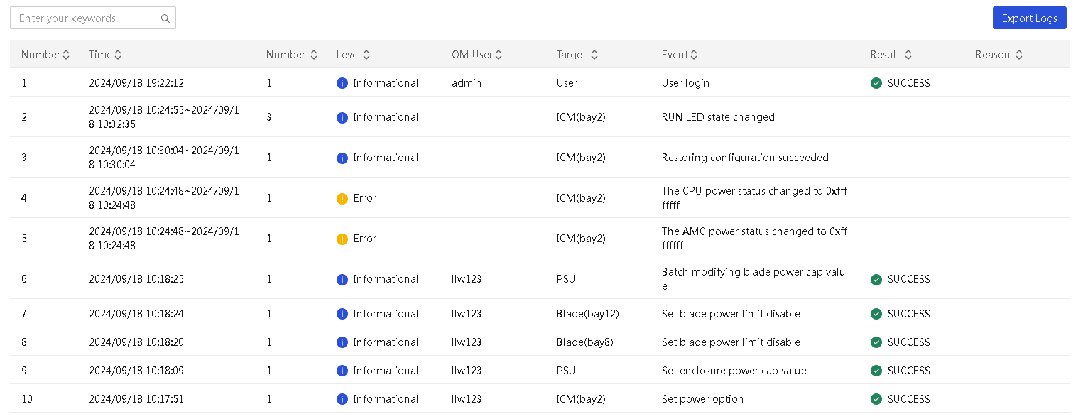
View system logs
About this task
Perform this task to view and export system logs of an enclosure. System logs records all events that occurred on an enclosure.
Restrictions and guidelines
Restarting an OM module or enclosure will clear all system logs of the OM module or enclosure.
The system can save a maximum of 100 system logs. When this limit is reached, the oldest system log is deleted.
You can export system logs within 31 days to a local file. Exported system logs will be removed from the System Logs page.
To view and export system logs of the past year, you must log in to the OM Web interface.
Procedure
1. In the navigation pane, select Menu > Devices > Enclosures.
2. Click View System Log in the Actions column for an enclosure.
The System Logs page opens.
3. To export the system logs, click Export Logs tab.
4. The system exports system logs of the past 31 days to a local file named sys_log.
Figure 49 Viewing the system logs of an enclosure
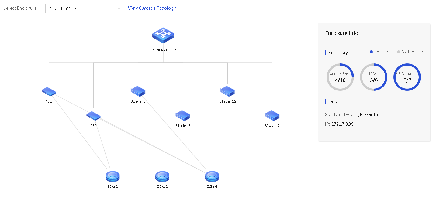
View the enclosure topology
About this task
Perform this task to view the internal topology and the cascade topology (if any) of an enclosure.
· Internal topology—Displays the blade servers, OM modules, mezzanine cards, interconnect modules, and AE modules as well as their interconnections in the enclosure. From the enclosure topology page, you can drill down to view detailed information about a blade server.
· Cascade topology—Displays enclosures cascaded to the enclosure.
Restrictions and guidelines
UniSystem can display the topology only for online enclosures. If an enclosure is offline or somehow cannot be connected, an offline tag is appended to the enclosure name and you cannot view the topology of the enclosure.
Procedure
1. In the navigation pane, select Menu > Devices > Enclosures > Enclosure Topology.
2. From the Select Enclosure, select the name of an enclosure to open its topology.
Figure 50 Enclosure topology
3. Click a blade server in the topology to open the Enclosure Network Topology Blade Server Details page for the server. The page displays the connections between interconnect modules and mezzanine cards on the server.
Figure 51 Enclosure Network Topology Blade Server Details page
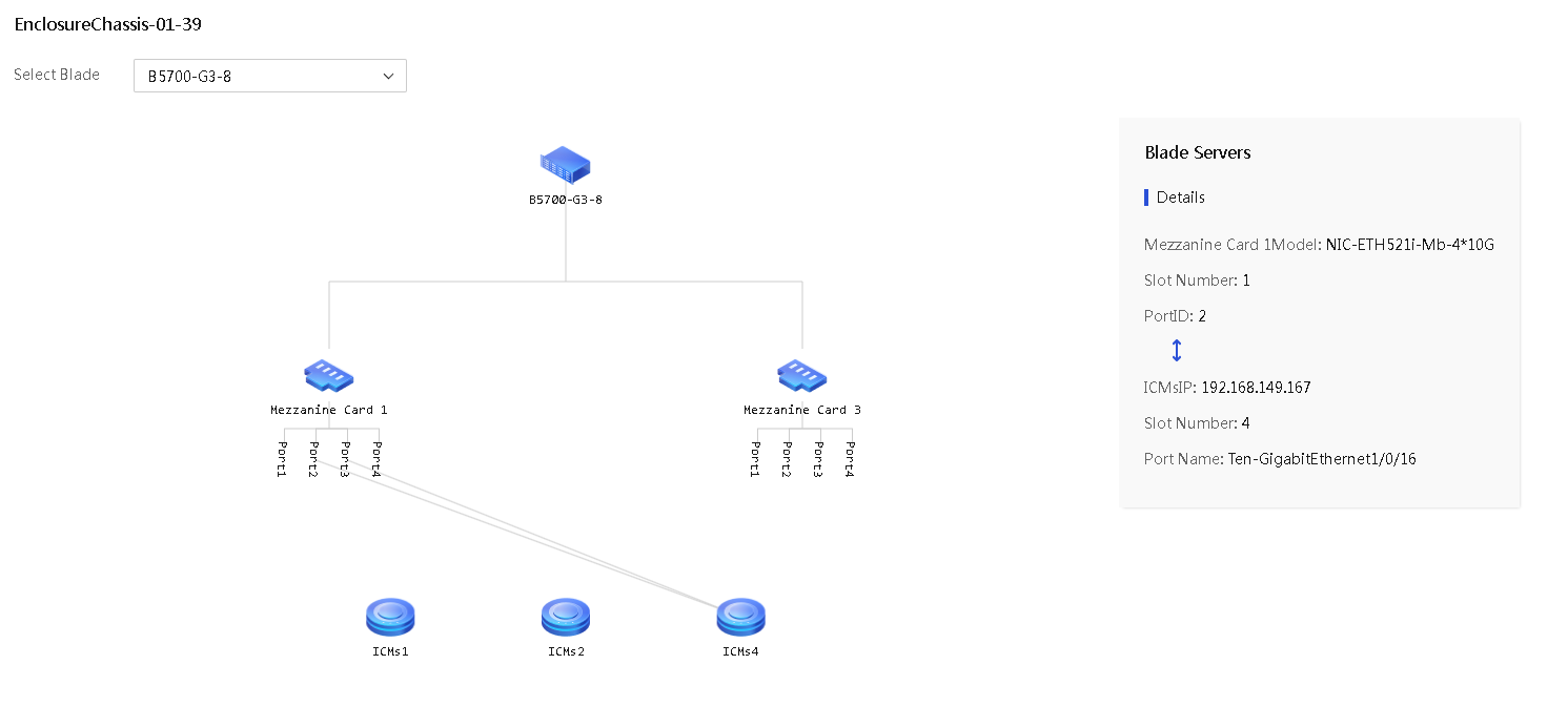
4. To view information about another blade server in the enclosure, select the server from the Select Blade list.
5. To view the cascade topology of the enclosure, click Back. On the Enclosure Topology page that opens, click View Cascade Topology next to the name of the enclosure. If View Cascade Topology is greyed out, it indicates that no enclosures are cascaded to the enclosure.
The Enclosure Cascade Topology page displays the enclosures cascaded to the enclosure. You can click an enclosure on this page to view its details, including the enclosure name, cascade number, enclosure IP address, and enclosure status.
Figure 52 Enclosure Cascade Topology page for an enclosure
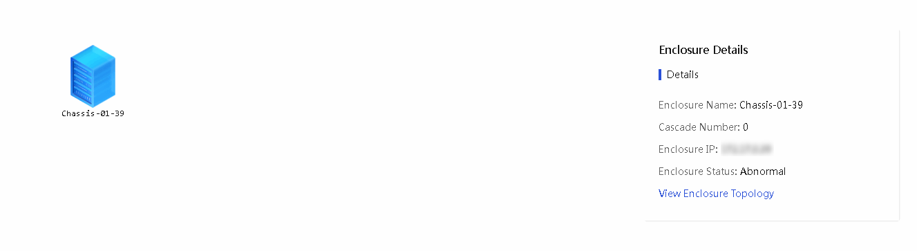
6. To return to the internal topology of the enclosure selected on this page, click View Enclosure Topology. This link is unavailable if the selected enclosure is not managed by UniSystem or is offline.
7. To return to the internal topology of the enclosure selected from the Select Enclosure list, click Back.
Manage servers
Manage servers
UniSystem can manage servers through HDM or FIST SMS installed on the servers.
With UniSystem, you can perform the following server management tasks:
· Add servers to UniSystem, edit server management settings in UniSystem, and delete servers from UniSystem.
· Launch a remote console to a managed server.
· View information about servers managed by UniSystem.
· Manage servers remotely from UniSystem. For example, you can power on or power off serves, turn on or off UID LEDs for servers.
General restrictions and guidelines
· If a device is managed by UniSystem, do not modify the device port number. If the port number is modified, you must add the device again or wait for a maximum of half an hour for the device to restore its port number automatically.
· When adding a FIST SMS server node to UniSystem, make sure the following requirements are met:
¡ The firewall is disabled on the server or port 12580 is added to the whitelist in the firewall.
¡ SELinux is disabled.
¡ The server has HDM installed and does not have an ongoing upgrade process.
¡ The server node can connect to the UniSystem server through the IP address of the operating system.
· When adding an HDM server node to UniSystem, make sure the following requirements are met:
¡ The UniSystem server can connect to the HDM dedicated network port or shared network port on the HDM server node.
¡ The access service ports used for communications with UniSystem are available on the HDM server node. Table 7 lists the default port numbers used by the access services.
To avoid IPMI communication failures, do not change the default ports used by the IPMI service.
Table 7 Default port numbers used by the access services
|
Service |
Default insecure port |
Default secure port |
|
CD-Media |
5120 |
5124 |
|
IPMI |
623 |
623 |
|
KVM |
7578 |
7582 |
|
SNMP Trap |
162 |
NA |
|
Web |
80 |
443 |
Manually add a server to UniSystem
About this task
Perform this task to manually add HDM or FIST SMS server nodes to UniSystem.
Procedure
1. In the navigation pane, select Menu > Devices > Servers.
2. Click Add.
3. In the Method dialog box, select Add Manually.
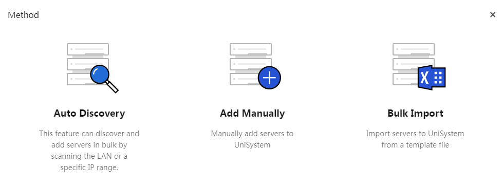
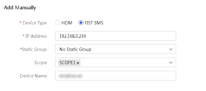
4. Enter the device information, select a static group, and select the scope:
¡ To add an HDM server node, select HDM for Device Type.
Specify the HDM IP address and device name.
In the Username and Password fields, specify the username and password of an HDM administrator account in UniSystem. If a non-administrator account is specified, some of the server management functions provided by UniSystem will be unavailable on the HDM server node.
An HDM server node can be managed by multiple UniSystem servers.
Figure 54 Adding an HDM server node

¡ To add a FIST SMS server node, select FIST SMS for Device Type. Specify the FIST SMS IP address and name of the server.
Figure 55 Adding a FIST SMS server node
5. Click OK.
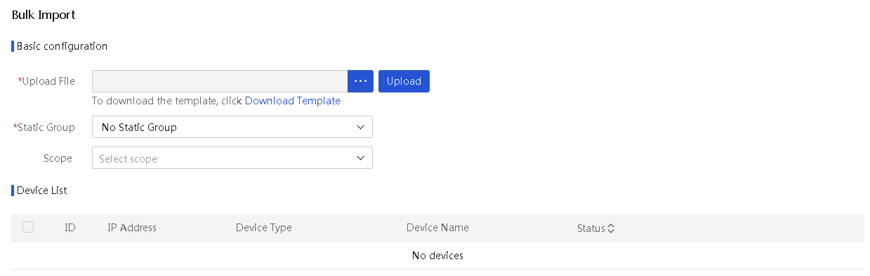
Import servers
About this task
Perform this task to import servers to UniSystem from a file.
Prerequisites
Before you import servers to UniSystem, first prepare a valid import file that contains the servers you want to import. You can download the import file template on the Import Devices page and then fill in the device information as needed.
Table 8 lists the supported templates.
|
Template |
Description |
|
template-1.txt |
Each line represents a device in the format of "IP address, username, password, device name." For HDM devices, fill in the IP address, username, and password. For FIST SMS devices, only the IP address is required. The device name is an optional field. |
|
template-2.xlsx |
Each line represents a device in the format of "device type in the first column, IP address in the second column, username in the third column, password in the fourth column, device name in the fifth column". For HDM devices, fill in the device type, IP address, username, and password. For FIST SMS devices, only the device type and IP address are required. The device name is an optional field. |
|
template-3.xls |
Each line represents a device in the format of "device type in the first column, IP address in the second column, username in the third column, password in the fourth column, device name in the fifth column". For HDM devices, fill in the device type, IP address, username, and password. For FIST SMS devices, only the device type and IP address are required. The device name is an optional field. |
Procedure
1. In the navigation pane, select Menu > Devices > Servers.
2. Click Add, and then select Bulk Import.
3. In the Upload File field, click … to select the import file, and then click Upload to upload the file.
UniSystem displays all devices in the file on the device list.
4. Select a static group.
5. Select a scope.
6. Select the servers you want to import to UniSystem, and then click OK.
The import process might take a while.
Figure 56 Bulk importing servers to UniSystem
Add servers through auto discovery
About this task
Auto discovery allows you to search the network for servers by using Simple Service Discovery Protocol (SSDP) or by using IP subnet scanning and add the found servers to UniSystem. Both HDM server nodes and FIST SMS server nodes can be added through auto discovery.
Restrictions and guidelines
The SSDP method is available only for G6 servers and servers of later generations.
· UniSystem management of servers can only be implemented in Layer 2 networks.
· UniSystem and HDM must be enabled with IPv6. HDM must also be enabled with SSDP and uses port 1900 for listening.
Procedure
1. In the navigation pane, select Menu > Devices > Servers.
2. Click Add, and then select Auto Discovery.
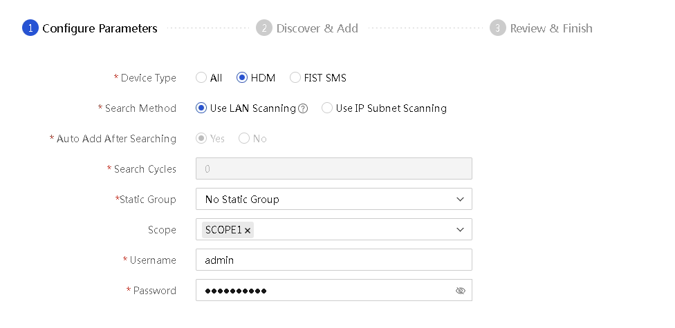
3. Select the device type and the search method.
¡ To search for HDM server nodes only or for both FIST SMS and HDM server nodes, select HDM or All for Device Type.
- If you select Use IP Subnet Scanning, enter the start and end IP addresses of an IP address range.
- If you select Use LAN Scanning, enter the HDM login username and password of the servers.
Figure 57 Searching for both HDM and FIST SMS nodes or for HDM nodes only
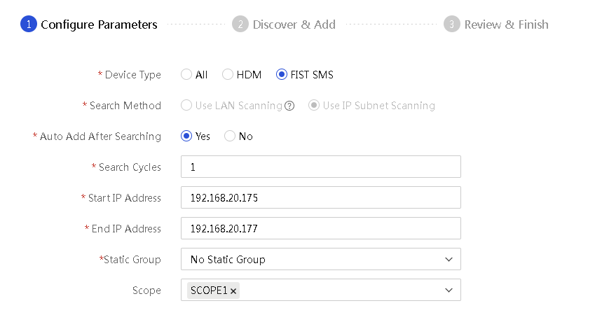
¡ To search for FIST SMS server nodes only, select FIST SMS for Device Type. Only the IP subnet scanning method is supported for this device type. Enter the start and end IP addresses of an IP address range.
Figure 58 Searching for FIST SMS server nodes only
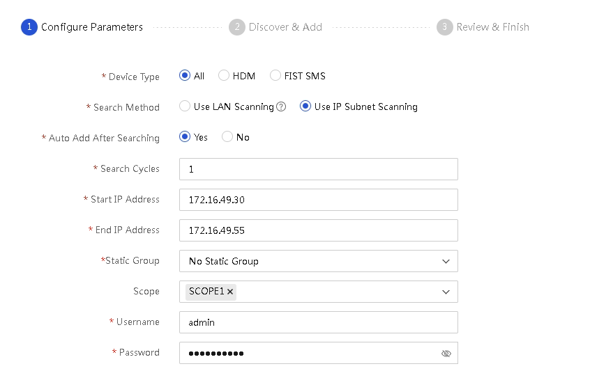
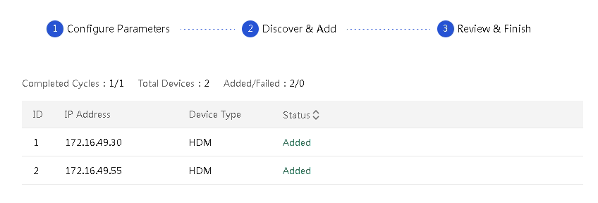
4. Select whether to add the discovered servers automatically.
¡ If you select Use LAN Scanning for Search Method, the discovered servers will be added automatically by default.
¡ If you select Use IP Subnet Scanning for Search Method and select Yes for Auto Add After Searching, enter the number of search cycles in the Search Cycles field.
Figure 59 Adding discovered servers automatically
5. Select a static group.
6. Select a scope.
7. Click Search.
¡ If you select No for Auto Add After Searching, select servers to be added from the discovered server list, and then click Add.
Figure 60 Adding selected servers to UniSystem

¡ If you select Yes for Auto Add After Searching, UniSystem automatically adds a server once it discovers the server. To abort the process, click Abort at the upper right corner of the discovered server list.
Figure 61 Automatically adding discovered servers to UniSystem
8. To go back to the Server page and view the newly added servers, click Back in the upper left corner of the page.
Configure IP settings in bulk
Introduction
Perform this task to edit the HDM management IP addresses of multiple servers in bulk by using IP configuration template files. The servers can be those managed by UniSystem or those not managed. This feature is available only for servers using HDM-3.10 or a later version.
|
|
NOTE: If you modify the IP addresses of the HDM dedicated network port and the shared network port at the same time, set the IP addresses on different network segments. If the IP addresses are on the same subnet, server network failures may occur. |
UniSystem supports batch setting of IP addresses in the following ways:
· IP Address—Applicable to scenarios where the server’s default HDM management IP address has been changed.
¡ Make sure the UniSystem management IP address and the server's current HDM management IP address are on the same network segment.
¡ When you fill in the template, the server's current HDM management IP address is required.
· Port MAC—Applicable to scenarios where the server’s default HDM management IP address has not been changed.
¡ Make sure the UniSystem management IP address and the server's current HDM management IP address are in the same Layer 2 network and can communicate with each other at Layer 2.
¡ Make sure the IPv6 function is enabled for the UniSystem management interface and the server's current HDM management interface, and the local link addresses of both interfaces start with fe80.
¡ When you fill in the template, the MAC address of the server's current HDM management interface is required.
· Serial Number—Applicable to scenarios where the server’s default HDM management IP address has not been changed.
¡ Both SSDP and non-SSDP methods are supported.
¡ To modify the IP address through SSDP (supported only by G6 and later servers):
- Make sure the SSDP function of the server HDM is enabled and the port number is 1900.
- Make sure the UniSystem management IP address and the server's current HDM management IP address are in the same Layer 2 network and can communicate with each other at Layer 2.
- Make sure the IPv6 function is enabled for the UniSystem management interface and the current HDM management interface of the server, and the local link addresses of both interfaces start with fe80.
- When you fill in the template, the server's serial number is required.
¡ To modify IP address through the non-SSDP method:
- Make sure the UniSystem management IP address and the server's current HDM management IP address are on the same network segment.
- When you fill in the template, the server's serial number is required.
Procedure
1. In the navigation pane, select Menu > Devices > Servers.
2. Click Bulk IP Settings. The Bulk IP Settings page as shown in Figure 62 opens.
Figure 62 Configure IP settings in bulk
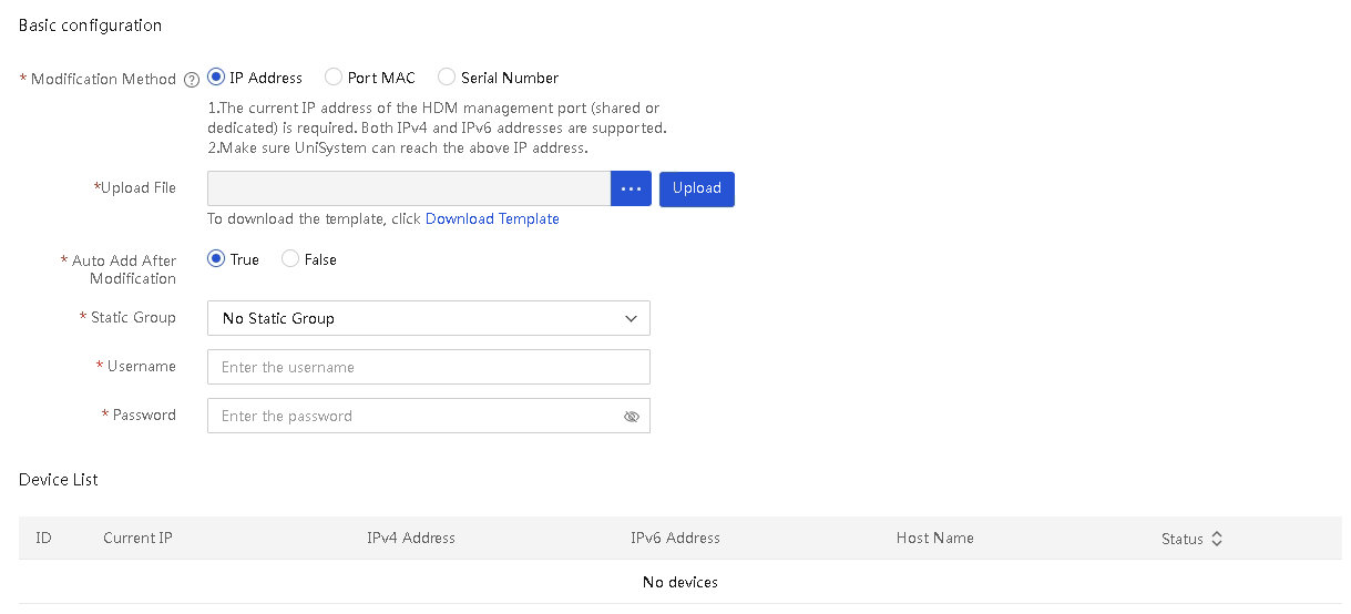
3. In the Modification Method filed, select a method to configure IP settings in bulk. Options include IP Address, Port MAC, and Serial Number.
4. To obtain the device file template, click Download Template.
5. Fill in the IP address, network port MAC address, or serial number of the target server according to the selected modification method. Specify the modified IP address information of the HDM dedicated network port or shared network port (including IPv4 and IPv6 addresses). For more information about the template filling requirements, see the README file downloaded together with the template.
6. In the Upload File field, click the … icon. In the dialog box that opens, select the device IP configuration file.
7. Click Upload. After upload, you can view the uploaded device information from the device list.
8. Configure the Auto Add After Modification field. If the servers are not required to be managed by UniSystem after the modification, you can select False. If the servers are required to be managed by UniSystem after the modification, select True.
9. (Optional.)Select a static group.
10. In the Username and Password fields, enter the HDM username and password of the target server, respectively.
11. Click OK to start editing HDM management IP addresses of the servers in bulk. If you select True for Auto Add After Modification, UniSystem will add the servers to the server list after the IP addresses are edited.
Figure 63 Device list in bulk IP settings
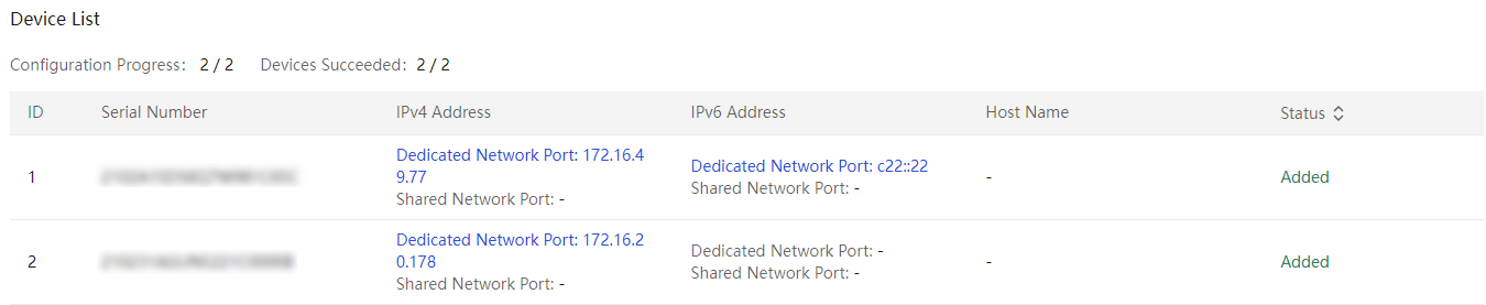
12. Click Back to return to the Server page.
Delete servers
About this task
Perform this task to delete servers from UniSystem.
Procedure
1. In the navigation pane, select Menu > Devices > Servers.
2. Select the servers you want to delete, click More in the top left corner, and then select Delete.
3. Click OK in the confirmation dialog box that opens.
Edit servers
About this task
Perform this task to bulk edit the names and HDM login credentials for servers managed by UniSystem.
Procedure
1. In the navigation pane, select Menu > Devices > Servers.
2. Select the target servers, click More, and then select Edit.
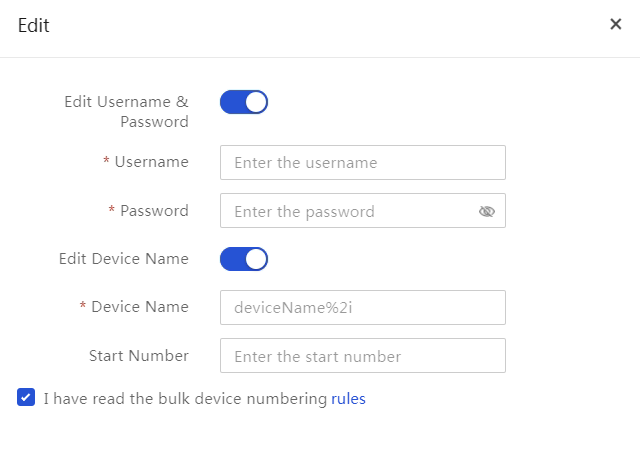
3. Select the Edit HDM Username & Password option, and then specify the new HDM login user name and password for the servers.
4. Select the Edit Server Name option, and then rename the selected servers as follows:
¡ To assign a unique name that contains an automatically generated sequence number to each server, enter the device name with string %*i and specify the start sequence number. Replace the asterisk (*) in the %*i string with the number of digits you want to include in the sequence number, which must be an integer in the range of 1 to 4. To use a one-digit sequence number, specify %*i as %1i or %i.
For example, with the device name set to UniSystem%4i and the start number set to 6, UniSystem will rename the first server as UniSystem0006 and subsequent servers as UniSystem0007, UniSystem0008, and so on.
¡ To assign a uniform name to all the selected servers, enter the server name and leave the Start Number field empty.
5. Click OK.
Figure 64 Editing server settings
Manage servers by group
This feature allows you to create static and dynamic groups for servers to facilitate server identification and filtering.
You can use the null keyword to filter out the -, N/A, and Unknown information.
Restrictions and guidelines
· The name and description of a dynamic group are case-sensitive strings that cannot exceed 255 characters. Only Chinese characters, digits, letters, spaces, and special characters `~!@#$%^&*()_+-=[]\{}|;':",./<>? are allowed and the strings cannot start or end with a space.
· The dynamic group name must be unique.
· You can specify a maximum of 6 query criteria for each dynamic group and the query criteria can be duplicate. A dynamic group must have a minimum of one query criterion.
· When you enter the value for a criterion type, a maximum of 64 characters are allowed. For text-type criterion type, only letters, digits, spaces, and special characters `~!@#$%^&*()_+-=[]\{}|;':",./<>? are allowed and the string cannot start or end with a space. For integer-type criterion type, only integers are allowed and the number cannot exceed 2147483647.
· The criterion type and sub-type are in English and do not change with the switch of the software language.
· The system adds the -copy string to the group name of a copied group. Make sure that the group name length does not exceed the upper limit.
· The name and description of a static group are case-sensitive strings that cannot exceed 255 characters. Only Chinese characters, digits, letters, spaces, and special characters `~!@#$%^&*()_+-=[]\{}|;':",./<>? are allowed and the strings cannot start or end with a space.
· The static group name must be unique.
Create a dynamic group
1. In the navigation pane, select Menu > Devices > Servers.
2. Click the ![]() icon to the right
of Dynamic Group and select Create
Dynamic Group.
icon to the right
of Dynamic Group and select Create
Dynamic Group.
Figure 65 Creating a dynamic group
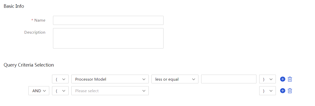
3. On the page that opens, enter basic information and specify query criteria.
4. Click OK.
Criteria types and arithmetic operator types
When you specify a query criterion, you must specify both the criterion type and arithmetic operator. Because different criterion types and arithmetic operators can form a large number of combinations, the system classifies arithmetic operators and criterion types as follows:
Table 9 Arithmetic operator types
|
Type |
Operators |
Application scenario |
|
Type 1 |
· not equal to · less than · less or equal · equals · greater than · greater or equal · is not null · is null |
Query integers |
|
Type 2 |
· not equal to · less than · less or equal · equals · greater than · greater or equal · is not null · does not contain · is null · contains · begins with · ends with |
Query strings |
|
Type 3 |
· not equal to · equals · is not null · is null |
Query enumerated information, such as status. |
Table 10 Criterion types
|
Criterion type |
Sub-type |
Operator type |
Value type |
|
Processor |
Processor Model |
Type 2 |
String. |
|
Base Frequency |
Type 1 |
Integer. |
|
|
Cores Number |
Type 1 |
Integer. |
|
|
Threads Number |
Type 1 |
Integer. |
|
|
Processor Status |
Type 3 |
Enumeration. |
|
|
Harddisk |
Harddisk Vendor |
Type 2 |
String. |
|
Harddisk Model |
Type 2 |
String. |
|
|
Firmware Version |
Type 2 |
String. |
|
|
Harddisk Status |
Type 2 |
String. |
|
|
Harddisk Type |
Type 3 |
Enumeration. |
|
|
Transmission Speed |
Type 2 |
String, such as 1.5 Gbps. |
|
|
Capacity |
Type 2 |
String, such as 1.81 TiB and 285 GB. |
|
|
Device |
Product Name |
Type 2 |
String, such as R4900 G6. |
|
IPv4 Address |
Type 2 |
String. This option also filters HDM and SMS IPv4 addresses. |
|
|
Host Name |
Type 2 |
String. |
|
|
Firmware |
Primary Partition HDM Version |
Type 2 |
String. |
|
Secondary Partition HDM Version |
Type 2 |
String. |
|
|
BIOS Version |
Type 2 |
String. |
|
|
CPLD Version |
Type 2 |
String. |
|
|
iFIST Version |
Type 2 |
String. |
Edit a dynamic group
1. In the navigation pane, select Menu > Devices > Servers.
2. Click the ![]() icon to the right
of a created dynamic group and select Edit.
icon to the right
of a created dynamic group and select Edit.
Figure 66 Editing a dynamic group
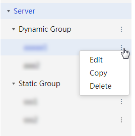
3. On the page that opens, enter basic information and specify query criteria.
Figure 67 Specifying editing information
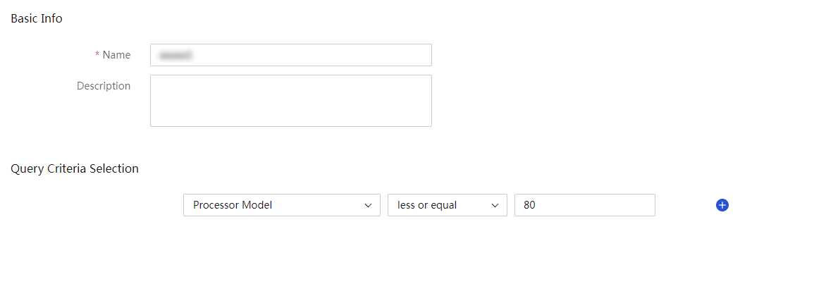
4. Click OK.
Copy a dynamic group
1. In the navigation pane, select Menu > Devices > Servers.
2. Click the ![]() icon to the right
of a created dynamic group and select Copy.
icon to the right
of a created dynamic group and select Copy.
Figure 68 Copying a dynamic group
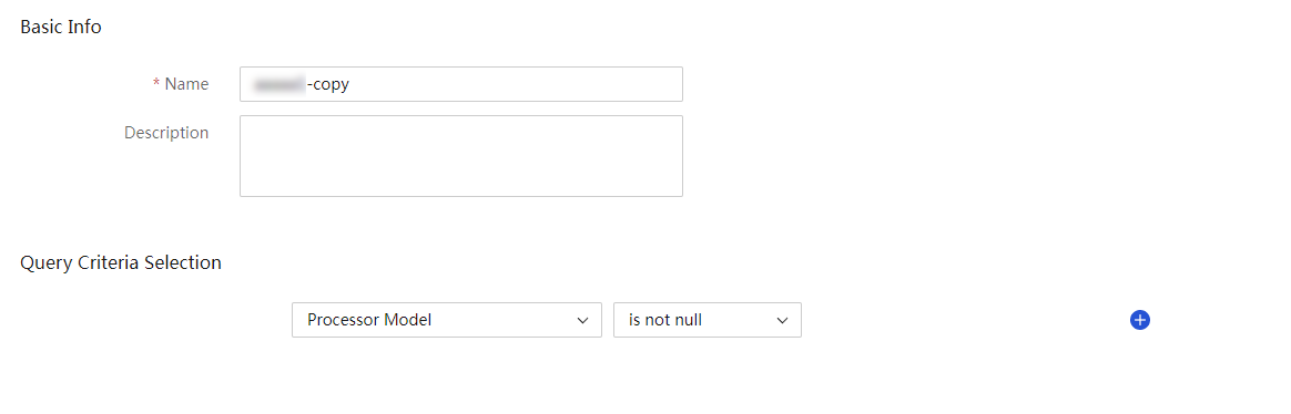
3. Click OK.
Delete a dynamic group
1. In the navigation pane, select Menu > Devices > Servers.
2. Click the ![]() icon to the right
of a created dynamic group and select Delete.
icon to the right
of a created dynamic group and select Delete.
Figure 69 Deleting a dynamic group
3. In the dialog box that opens, click OK.
Create a static group
1. In the navigation pane, select Menu > Devices > Servers.
2. Click the ![]() icon to the right
of Static Group and select Create
Static Group.
icon to the right
of Static Group and select Create
Static Group.
Figure 70 Creating a static group
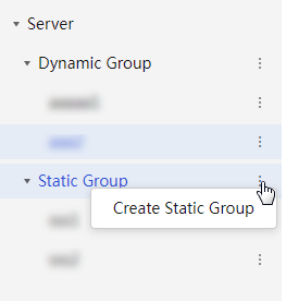
3. On the page that opens, enter basic information.
4. Enter basic information for the static group.
Figure 71 Entering basic information
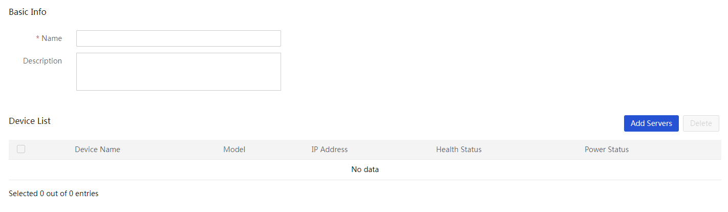
5. Click Add Servers. On the page that opens, select servers to be added and click OK.
Figure 72 Adding servers to the static group
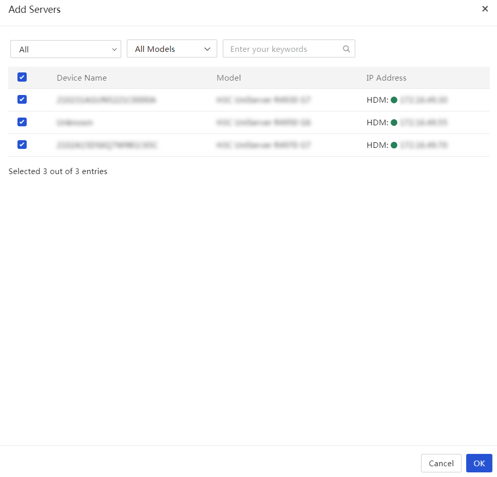
6. Click OK.
Edit a static group
1. In the navigation pane, select Menu > Devices > Servers.
2. Click the ![]() icon to the right
of a created static group and select Edit.
icon to the right
of a created static group and select Edit.
3. On the page that opens, enter basic information and click Add Servers to add servers to the group.
Figure 73 Editing a static group
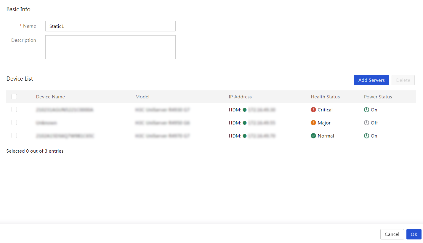
4. Click OK.
Copy a static group
1. In the navigation pane, select Menu > Devices > Servers.
2. Click the ![]() icon to the right
of a created static group and select Copy.
icon to the right
of a created static group and select Copy.
Figure 74 Copying a static group

3. Click OK.
Delete a static group
1. In the navigation pane, select Menu > Devices > Servers.
2. Click the ![]() icon to the right
of a created static group and select Delete.
icon to the right
of a created static group and select Delete.
3. In the dialog box that opens, click OK.
Figure 75 Deleting a static group
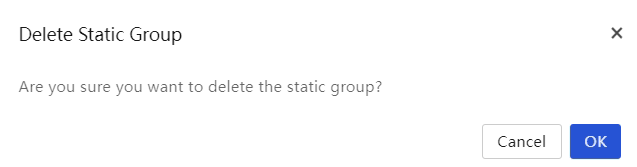
Launch a remote console
About this task
Perform this task to launch a KVM or H5 KVM remote consoles to configure and manage a server.
Restrictions and guidelines
· Only an account with the KVM remote control privilege can start the remote console.
· A maximum of four concurrent remote control sessions are supported.
· A flashing UID LED indicates that the remote console on a server is active.
Procedure
1. In the navigation pane, select Menu > Devices > Servers.
2. Click the KVM or H5 KVM in the Actions column for the target server.
View server information
View server details
About this task
You can view the detailed information of a server on the Server Details page, including summary, hardware details, temperature information, and power settings.
Restrictions and guidelines
UniSystem does not provide information about the power supplies or fans for a blade server.
Procedure
1. In the navigation pane, select Menu > Devices > Servers.
2. Click the name of the server whose detailed information you want to view.
3. On the Server Details page, click a tab to view the information displayed on the tab.
Available tabs include:
¡ Summary: Displays the overall health, status, and basic information of the server, and provides management options for the server.
Figure 76 Summary tab
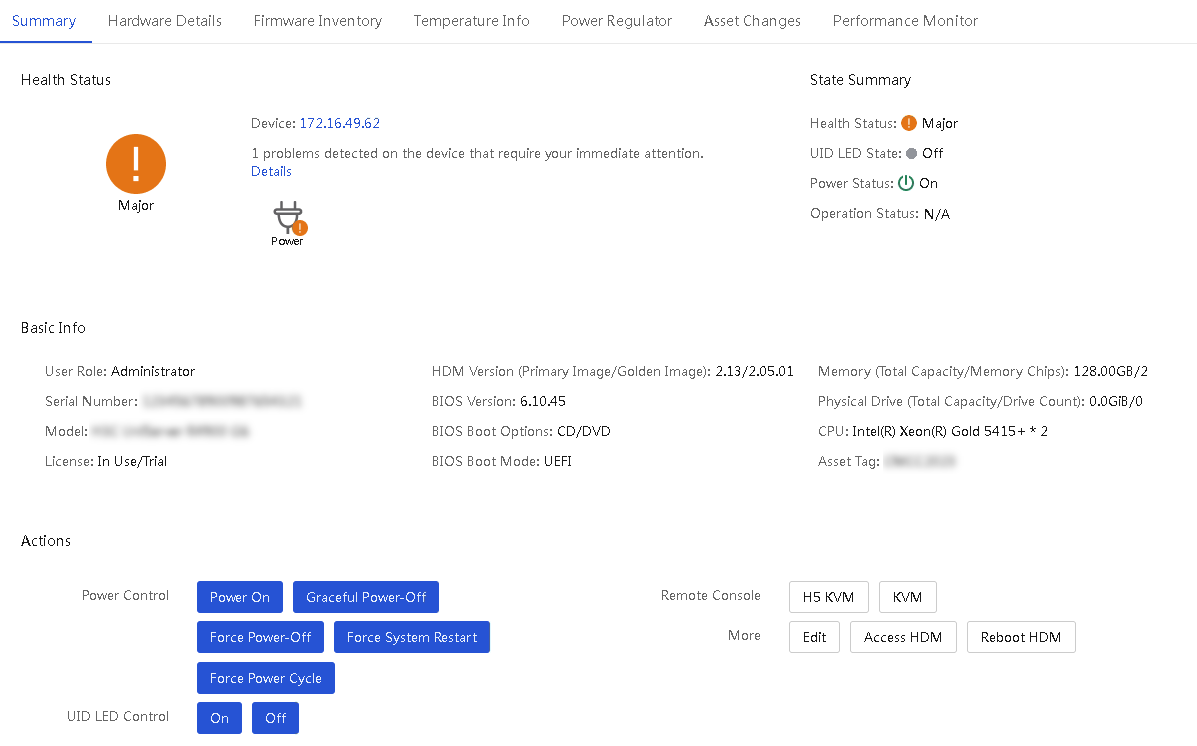
¡ Hardware Details: Displays information about the processors, memory, PCIe modules, storage controllers, logical drives, physical drives, power supplies, fans, and liquid-cooled module on the server.
Figure 77 Hardware Details tab
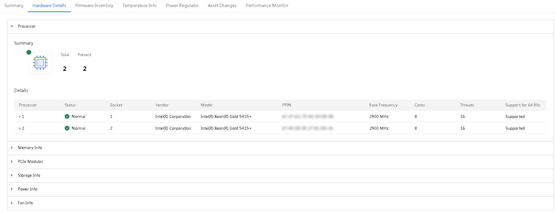
¡ Firmware Inventory: Displays the component models and version information for server firmware.
Figure 78 Firmware Inventory tab
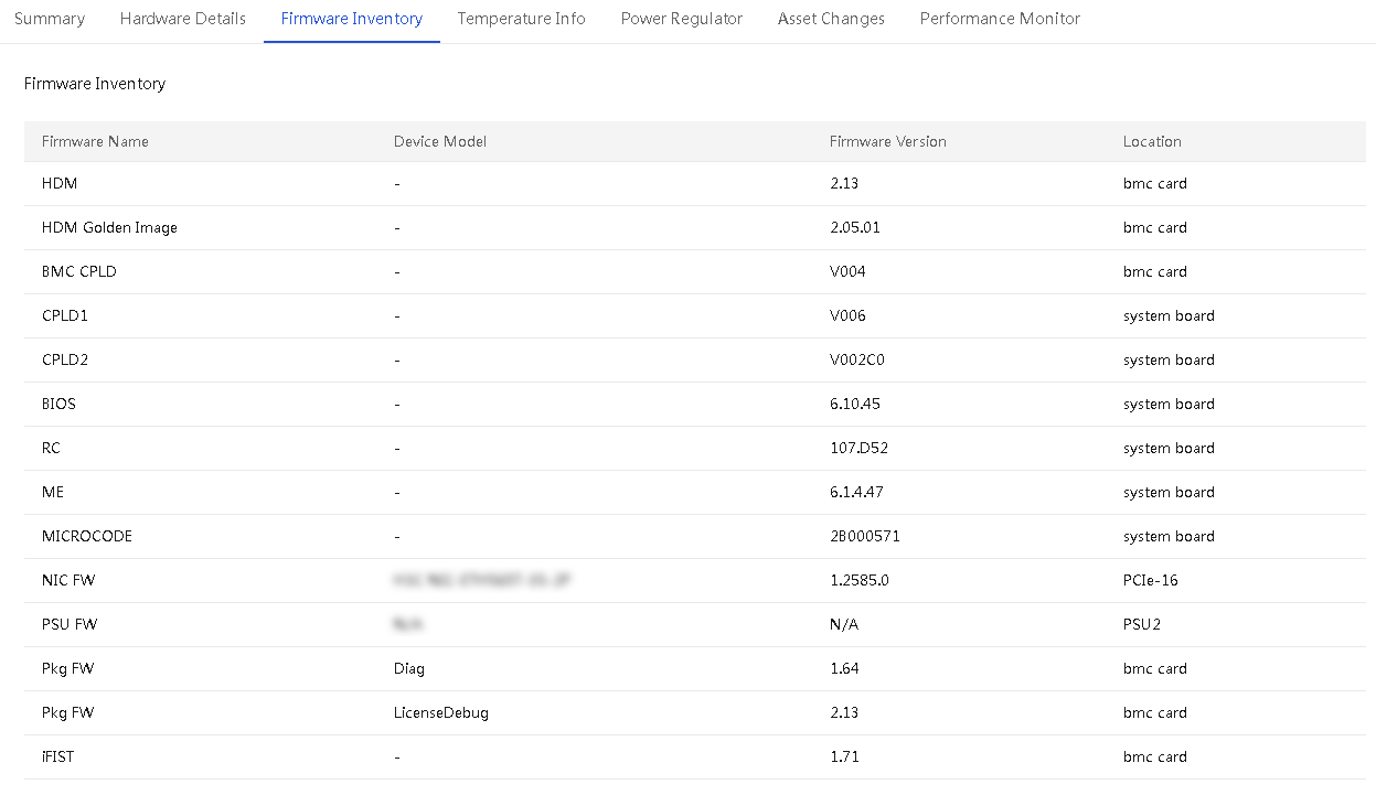
¡ Temperature Info: Displays temperature information about the server in a temperature heatmap. Hover over the map to view the temperature sensor name, status, and reading.
Figure 79 Temperature Info tab
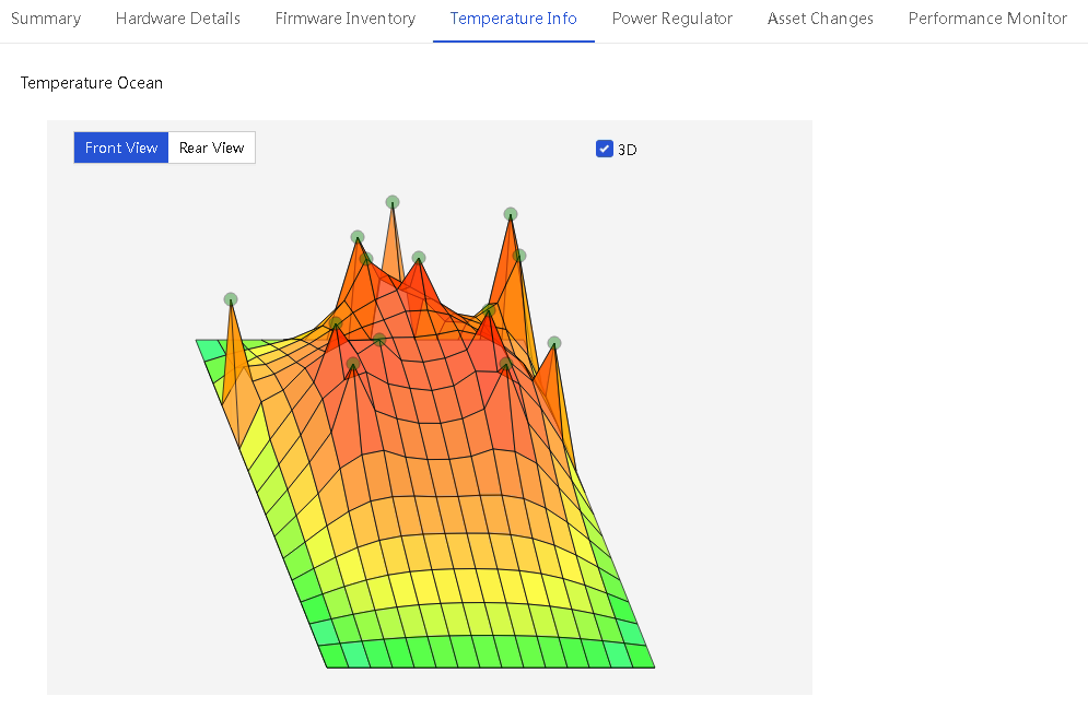
¡ Power Regulator: Allows you to view and configure power settings for the server. For information about how to set the power settings for the server, see "Configure power capping settings."
Figure 80 Power Regulator tab
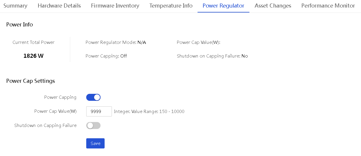
Configure power capping settings
About this task
From the Power Regulator tab of the Server Details page, you can configure the power capping settings for the server.
The power capping feature allows you to limit the power consumption of a server to a power cap value that is lower than or equal to the maximum rated power of the server.
When the power cap value is exceeded, the server attempts to decrease power consumption by automatically decreasing the operating frequency of system components such as processors. Power capping fails if the power consumption cannot drop below the power cap value in 30 seconds.
You can configure the server to shut down or continue to run on power capping failure.
Procedure
1. In the navigation pane, select Menu > Devices > Servers.
2. Click the name of a server to enter the server details page.
3. Click the Power Regulator tab.
4. Select Enable for Power Capping to enable power capping.
5. Set the power cap value.
Power capping is at the expense of system performance. Select the power cap value carefully to avoid undesirable decrease in performance, especially when the server contains power intensive components, such as GPUs and SSDs.
6. (Optional.) Enable or disable the Shutdown on Capping Failure feature as needed.
7. Click Save.
View server asset changes
About this task
Perform this task to view asset change information for a server.
Procedure
1. In the navigation pane, select Menu > Devices > Servers.
2. Click the device name link to enter the server details page.
3. Click the Asset Changes tab.
4. View the asset change information for the current server, including processor, memory, network adapter, PCIe device, fan, power, storage controller, FC HBA, drive, and GPU.
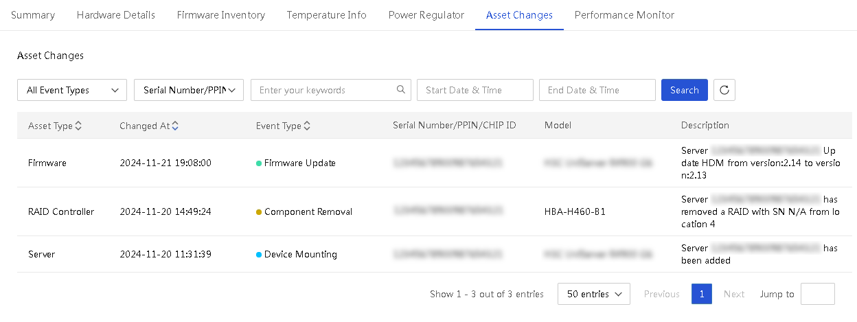
Table 11 Parameter description for asset changes
|
Parameter |
Description |
|
Asset Type |
Server type or specific component, including processor, memory, network adapter, PCIe device, fan, power supply, RAID controller, FC HBA, drive, and GPU. |
|
Changed At |
Time at which the asset change occurred. |
|
Event Type |
Event type for the asset change, including: · Device Mounting—Add the server to the UniSystem management list. · Component Adding—Install the component to the server. · Component Removal—Remove the component from the server. · Firmware Update—Update the HDM (primary and backup partitions), BIOS, ME, system board CPLD, or iFIST firmware. |
|
Serial Number/PPIN |
Device or component serial number or PPIN information. |
|
Model |
Device model information. |
|
Description |
Asset change description information. |
View performance monitoring data of a FIST SMS server node
About this task
For a FIST SMS server node, you can view its physical resource usage information on the Server Performance Monitor page. UniSystem collects the CPU usage, drive space usage, memory usage, network throughput, cache memory, GPU usage, drive I/O, drive throughput, drive read/write ratio, drive queue depth, I/O latency, NFS client read/write speed, NFS server read/write speed, system load, inlet temperature, and power information of managed FIST SMS server nodes at 30-second monitor intervals. You can view the past 30 days' resource usage data for a FIST SMS server.
The NFS server read/write speed, NFS client read/write speed, and system load are available only in Linux operating systems.
To monitor the NFS server read/write speed, GPU usage, disk information, and physical resources data that requires a CLI-based obtaining method, you must first configure the environment. For detailed information about the resource obtaining methods, see H3C Servers FIST SMS User Guide.
· GPU usage information: Requires installing and running nvidia-smi.
· NFS client read/write speed and NFS server read/write speed: Requires installing the NFS client and setting up the server environment.
To use the iostat tool that comes with the system to obtain resources, value obtaining fails if the corresponding field is missing in iostat. In this case, manual installation is required. To manually install iostat, use the software package manager or the source code. To use the source code method, use the symbolic link to replace the iostat file path. The iostat tool is in the /usr/bin/ directory.
If the FIST SMS of a server is not added to UniSystem, the performance monitoring page of the server displays only the history power and temperature trend graphs for the server.
Restrictions and guidelines
· If UniSystem failed to obtain the server information for a monitoring period, the data corresponding to the monitoring period is displayed as empty. A message is displayed to indicate that the connection to the FIST SMS node failed.
· When the usage of a specific type of resources exceeds the corresponding alarm threshold, the server will send the corresponding SNMP alarms. When the usage drops below the threshold, the server will send messages for clearing the SNMP alarms. To use UniSystem to listen to SNMP alarms, configure related functions on the alarm forwarding page. For more information, see "Alarm configuration."
Procedure
1. In the navigation pane, select Menu > Devices > Servers.
2. Click the device name of the FIST SMS server whose monitoring data you want to view.
3. Click the Monitor tab.
The tab displays the following physical resource usage information of the FIST SMS server node:
¡ CPU Usage: Displays the CPU usage of applications running on the server.
¡ Drive Usage: Displays the percentage of used drive space to the total available drive space for the server.
¡ Memory Usage: Displays the percentage of memory space used by all processes to the total available memory space.
¡ Network Throughput: Displays the transmission and receiving rates (in Mbps) of the selected network adapter. In the upper right corner of the line chart, select the MAC address of the network adapter whose data you want to view.
¡ History Temperature: Displays inlet temperature change trend of the server.
¡ History Power: Displays power change trend of the server, in watts.
¡ CPU Usage Alarm Threshold: Threshold for the CPU usage to trigger an alarm. The value 0 indicates disabling alarming.
¡ Memory Usage Alarm Threshold: Threshold for the memory usage to trigger an alarm. The value 0 indicates disabling alarming.
¡ Drive Usage Alarm Threshold: Threshold for the drive usage to trigger an alarm. The value 0 indicates disabling alarming.
¡ Cache Memory (MB): Cache memory size.
¡ GPU Usage: Percentage of GPU resources used by running services to the total available GPU resources.
¡ Drive I/O (operations/s): Drive read/write in a given unit of time.
¡ Read/Write Ratio: Percentage of drive read/write operations to the total read/write operations in a given unit of time.
¡ Drive Queue Depth (operations): Average queue length for drive read/write operations in a given unit of time.
¡ Drive Throughput (kb/s): Read and write throughput in a given unit of time.
¡ I/O Latency (ms): Average waiting time for a drive read/write operation to finish in a queue in a given unit of time.
¡ NFS Client Read/Write Speed: Data amount of NFS client read/write operations in a given unit of time.
¡ NFS Server Read/Write Speed: Data amount of NFS server read/write operations in a given unit of time.
¡ System Load: Computing workload of the computer system in a given unit of time.
Each line chart shows data collected over a time span of 3 hours.
Figure 82 Server Performance Monitor page (1)
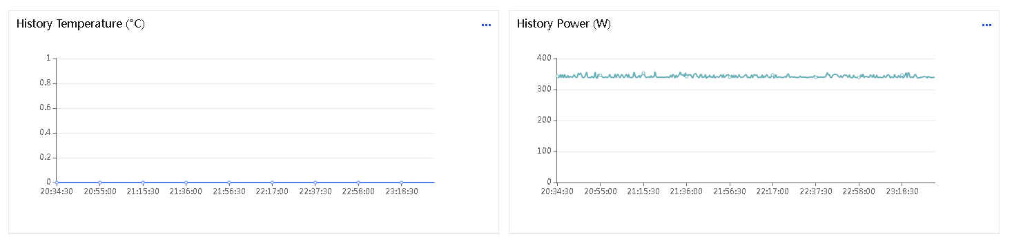
Figure 83 Server Performance Monitor page(2)
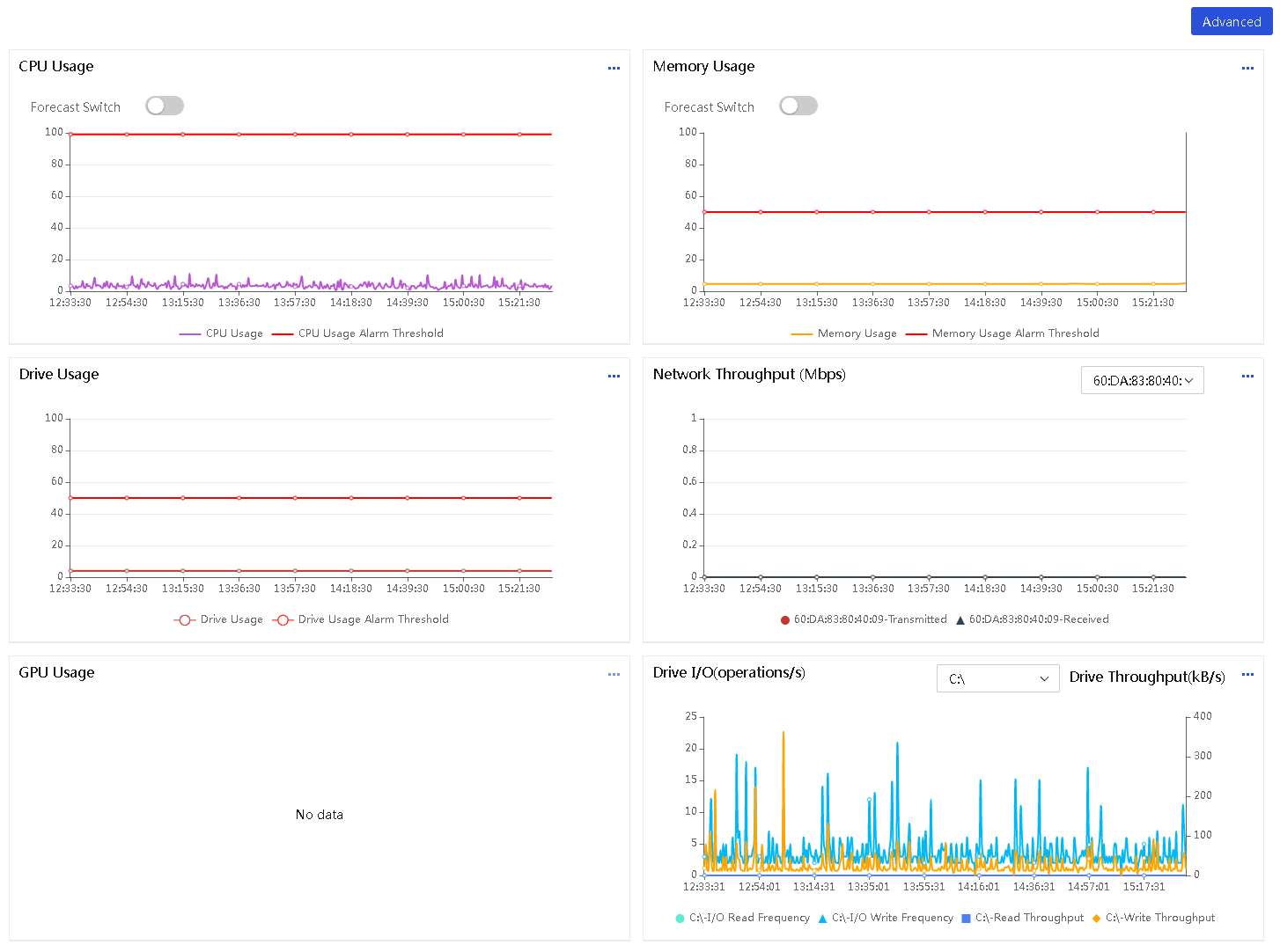
4. Roll the mouse wheel to adjust the size of a chart and view the data for each monitoring period.
5. (Optional.) Click Advanced. You can view and set the usage alarm thresholds of the server. After you set a threshold, the threshold will be marked by a red line in the line chart.
Manage servers remotely through UniSystem
Power on or power off servers
About this task
Perform this task to power on or power off servers remotely from UniSystem.
Restrictions and guidelines
If you use UniSystem to power on a large number of servers at the same time, the electric current might be too large. As a best practice, operate these servers in multiple batches and power on servers in staggered shifts.
Procedure
1. In the navigation pane, select Menu > Devices > Servers.
2. Select the target servers, click More, and then select Power Control.
3. Select one of the following power options as needed:
¡ Graceful Power-Off: Power off the servers gracefully. This button mimics a physical momentary press of the power button on the server.
¡ Force Power-Off: Force the servers to power off. This button mimics a physical press and hold of the power button on the server.
¡ Force System Restart: Reboot the servers without powering off them.
¡ Force Power Cycle: Force the servers to reboot immediately.
¡ Power On: Power on the servers. This button mimics a physical momentary press of the power button on the server.
4. In the dialog box that opens, select Operating instructions lick OK.
Figure 84 Powering on or powering off servers

Download SDS logs
About this task
Perform this task to download and save SDS logs of managed servers to local .sds files.
Procedure
1. In the navigation pane, select Menu > Devices > Servers.
2. Select the servers whose SDS logs you want to download, click More, and then select Download SDS Logs.
3. Select whether to download all SDS logs or only SDS logs generated during a specific time range.
4. To download only SDS logs generated during a specific time range, specify the log generation time range as needed.
5. Click OK.
UniSystem starts to download the SDS logs of the selected servers and displays the device-specific downloading progress on the device list.
Figure 85 Downloading SDS logs
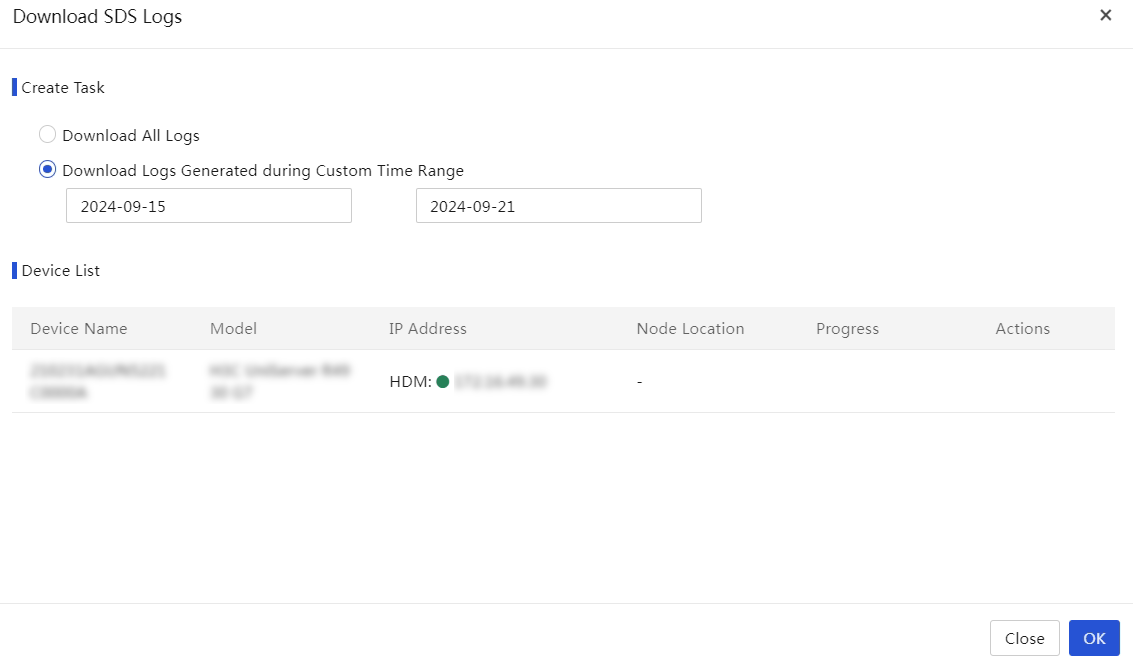
Export the configuration information of servers
About this task
Perform this task to export the basic configuration information of selected servers to .json files. The exported information includes the server model, HDM IP address, BIOS/HDM version, processor, memory, storage, and PCIe module information.
UniSystem exports the configuration information of each selected server to a separate file. In addition, it creates a file to record all servers (identified by their names) and their PCIe module information. All those files will be compressed to an archive and can be downloaded locally.
Procedure
1. In the navigation pane, select Menu > Devices > Servers.
2. Select the servers whose configuration information you want to export, click More, and then select Configuration List.
3. Click OK to export the configuration of the selected servers.
4. Save the exported server configuration file to the local device.
Figure 86 Exporting the configuration information of selected servers
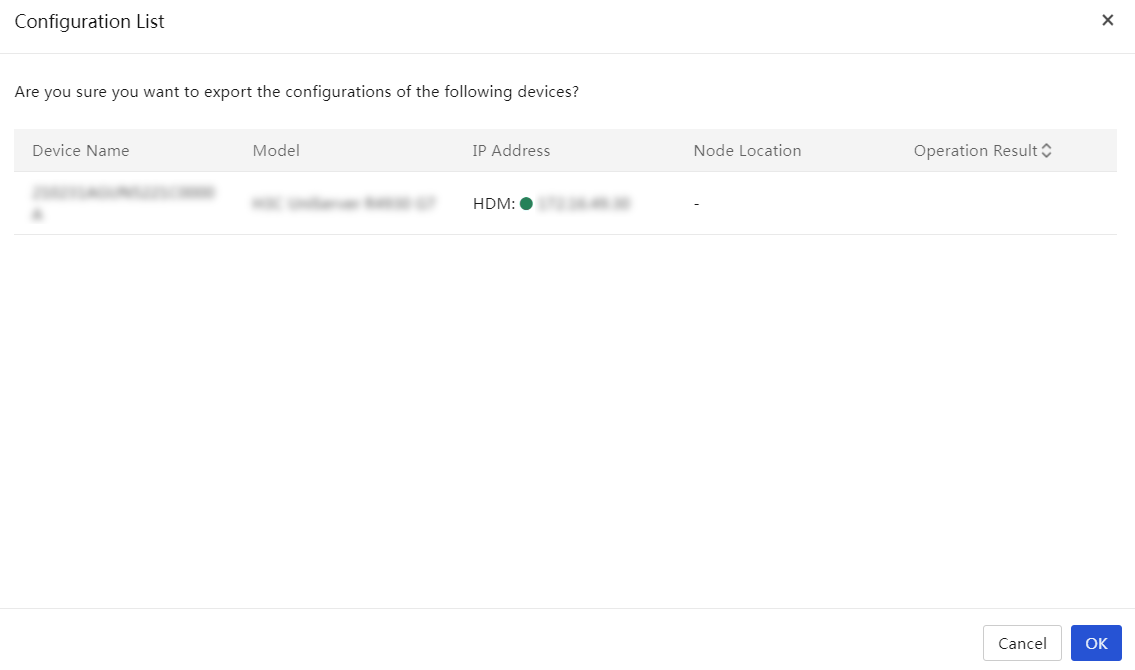
Reboot HDM
About this task
Perform this task to reboot HDM on selected servers.
Restrictions and guidelines
· Rebooting HDM on a server will temporarily disconnect the server from UniSystem. The connection is automatically restored after HDM starts up.
· Video files cannot survive an HDM reboot. Back up the video files on a server before you reboot HDM on the server.
· To avoid HDM and operating system anomalies, do not power on or power off the server during the HDM reboot process.
Procedure
1. In the navigation pane, select Menu > Devices > Servers.
2. Select the target servers, click More, and then select Reboot HDM.
3. Verify the operation information, and then select I have read and understood the consequences of this operation.
4. Click OK.
Figure 87 Rebooting HDM on selected servers
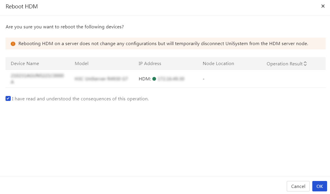
Leakage handling strategy
This feature is used to configure the leakage handling strategy for liquid-cooled servers. Once successfully set up, the strategy will automatically apply to the device. If you select the auto shutdown strategy, UniSystem automatically shuts down the server to prevent liquid leaks from spreading or damaging device.
Restrictions and guidelines
· If you select a non-liquid-cooled server for the strategy, the strategy configuration fails for the server, which is normal.
· After successful configuration, you can enable alarm monitoring in the UniSystem alarm forwarding module to view leakage alarm information.
Procedure
1. In the navigation pane, select Menu > Devices > Servers.
2. Select the target servers, click More, and then select Leakage Handling Strategy.
3. Select the leakage handling strategy, confirm the device list, and then click OK.
Figure 88 Configuring the leakage handling strategy
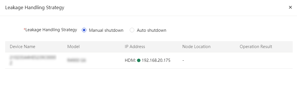
Manual fault reporting
About this task
Perform this task to report faults manually.
Prerequisites
Enable and save repair parameters. For more information, see "Remote control."
Procedure
1. In the navigation pane, select Menu > Devices > Servers.
2. Select the target servers, click More, and then select Fault Report.
The system prompts that the fault report operation succeeded.
You can check the fault repair tasks to view the fault report status.
Figure 89 Manual fault reporting
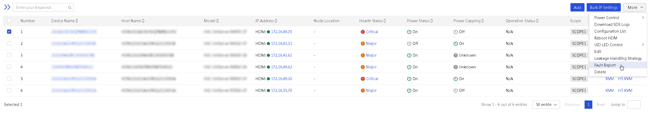
Synchronize U-Center
UniSystem of the unified O&M version supports synchronizing the devices in the server list to the managed device list of U-Center.
Procedure
1. In the navigation pane, select Menu > Devices > Servers.
2. Select the servers you want to synchronize, click More in the Actions column, and then select Sync U-Center.
3. Click Protocol Check in the dialog box that opens. UniSystem confirms whether to check the SNMP protocol when synchronizing U-center with the target server.

¡ If the selected server can be synchronized directly to U-Center without checking the SNMP protocol, click OK in the confirmation dialog box.
¡ If the selected server requires checking the SNMP protocol to synchronize with U-Center, click Configure or Bulk Configure on the SNMP Protocol Server page to configure SNMP as shown in Figure 91. The parameters include SNMP Version, Read-Only Community String, and Read/Write Community String. Click OK to complete the synchronization.
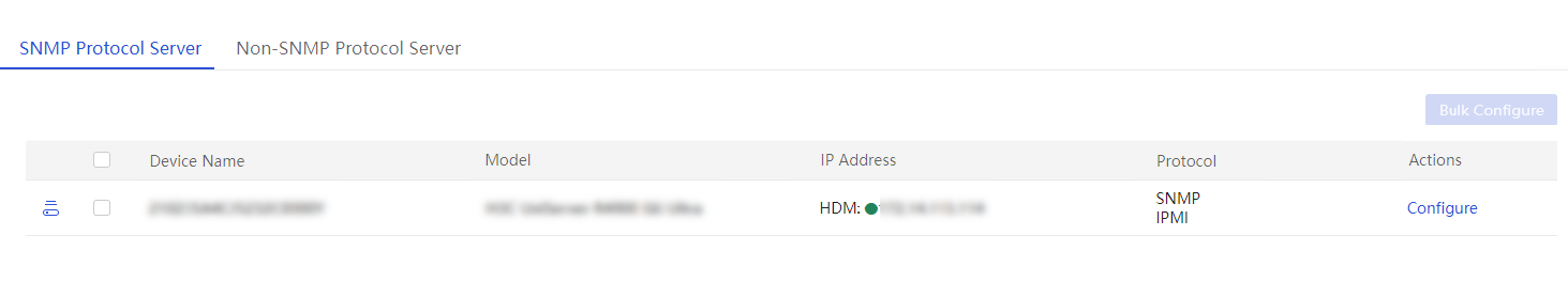
Manage switches
UniSystem can manage switches of the following models:
· H3C S6800-54QT
· H3C S6850-56HF
· H3C S6800-54QF
· H3C UIS M8380-C
· H3C UIS M8310
· H3C S6850-56HF-CP
· H3C S6850-56HF-IM
Use the switch management functions
Perform this task to manage switches. For example, you can add and delete a switch, update the user settings for a switch, and log in to the SSH console of a switch.
Add a switch
About this task
Perform this task to add switches to UniSystem for management. You can add up to 30 switches to UniSystem.
Prerequisites
· Obtain the management IP address of the switch.
· Obtain the username and password of the system user that has admin privilege to manage the switch, and specify that the user can use the HTTP service.
· Enable NETCONF over SOAP on the switch.
· Make sure the network where UniSystem resides and the management network of the switch to be added can reach each other.
Procedure
1. Obtain the management IP address of the switch and the username and password of the system user that has admin privilege to manage the switch.
2. Log in to the CLI of the switch and perform the following steps:
# Enable NETCONF over SOAP on the switch.
[Sysname] netconf soap http enable
# Enter the system user view and specify that the user can use the HTTP service. This example uses user admin.
[Sysname] local-user admin
[Sysname-luser-manage-admin] service-type http
3. Add a secondary IP address that belongs to the management network of the switch:
a. Execute the display ip interface brief command on the switch. As shown in Figure 92, the IP address of the M-GE0/0/0 port is the management IP address of the switch.
Figure 92 Obtaining the management IP address of the switch
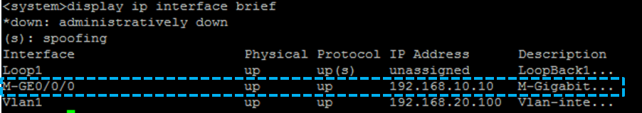
4. Add the switch to UniSystem:
a. Log in to UniSystem.
b. In the navigation pane, select Menu > Devices > Switches.
c. Click Add Switch. In the dialog box that opens, enter related information and click OK.
Figure 93 Adding a switch
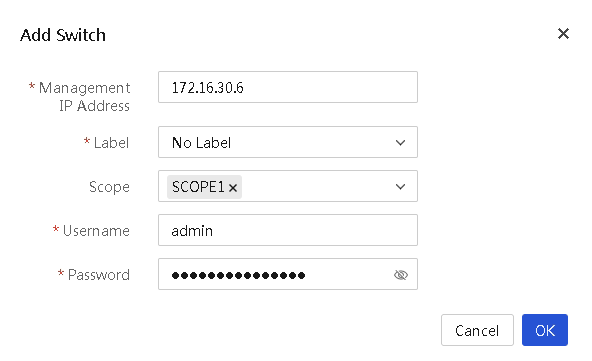
d. Verify that the newly added switch is displayed on the Switches page.
Figure 94 Adding a switch
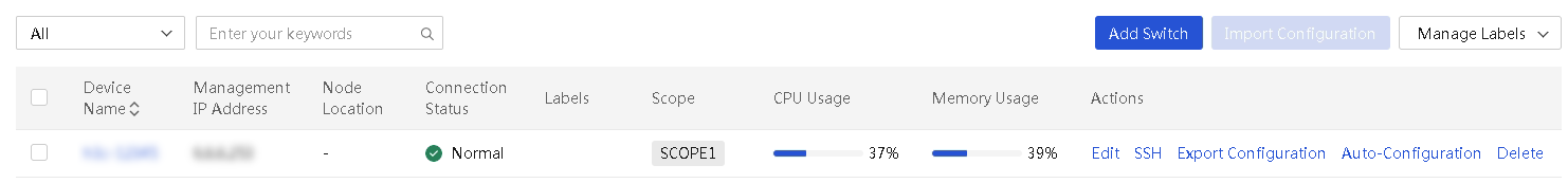
Log in through SSH console
About this task
Through the SSH console, you can log in to the managed switch through SSH and open the CLI of the switch. To use this function, make sure the SSH service is enabled on the managed switch and the login user supports the SSH service.
Restrictions and guidelines
· If the SSH remote console window fails to be loaded correctly, click the link provided at the bottom of window to load the certificates on a new page. After the load is completed, return to the remote console window and click Refresh. If you will not use the SSH console for a long period of time, execute a command to exit the SSH console.
· When you are using the SSH console to log in to the CLI of the managed switch, do not click Refresh. Otherwise, you will be logged out.
· The SSH feature is not available if you set up the UniSystem environment in a Windows operating system and add switches to UniSystem.
Procedure
1. In the navigation pane, select Menu > Devices > Switches.
2. Click SSH in the Actions column for the switch.
Figure 95 Log in to a switch through SSH
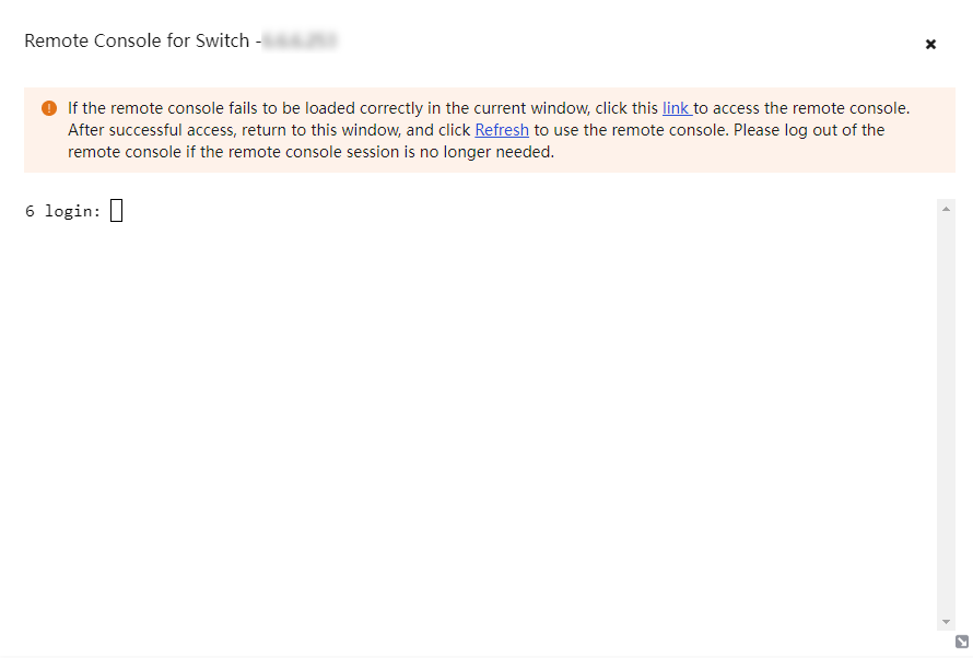
Export the configuration of a switch
About this task
Perform this task to export the configuration of a switch and save the exported switch configuration in a switch configuration template on the Menu > Templates > Switch Templates page.
This feature is available only for H3C S6850-56HF and H3C S6800-54Q switches.
Restrictions and guidelines
· Do not operate on the switch (through CLI, SNMP, or other methods) while UniSystem is exporting the switch configuration.
· Configuration export is a resource-intensive operation. Make sure the switch has enough resources before you export its configuration.
· Do not set the name of a switch configuration template to UniSystem.cfg.
Procedure
1. In the navigation pane, select Menu > Devices > Switches.
2. Click Export Configuration in the Actions column for the switch whose configuration you want to export.
3. In the dialog box that opens, perform the following:
¡ Enter a description.
¡ Select the scope to which the switch template belongs.
4. Click OK.
Import configuration to a switch
About this task
Perform this task to import the configuration in a switch configuration template to a managed switch.
This feature is available only for H3C S6850-56HF and H3C S6800-54Q switches.
Restrictions and guidelines
· After you import configuration to a switch, UniSystem might fail to communicate with the switch because of switch address conflicts. To resolve the issue, manually edit the IP address of the switch and add the switch to UniSystem again.
· Do not import configuration to a switch on which the configuration export operation in progress.
· You can import configuration to a switch only by using a switch configuration template with a matching switch model.
· Do not operate on the switch (through CLI, SNMP, or other methods) while UniSystem is importing configuration to the switch.
· Configuration import is a resource-intensive operation. Make sure the switch has enough resources before you import configuration to it.
Procedure
1. In the navigation pane, select Menu > Devices > Switches.
2. Select the target switch, and then click Import Configuration.
3. In the dialog box that opens, select the configuration template you want to import to the switch, and then click OK.
Figure 96 Selecting a configuration template to import to the switch
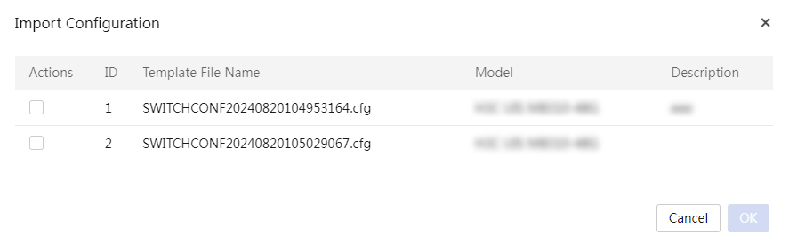
Configure auto-configuration
The auto-configuration feature allows you to bind a server template to a switch port to enable automated configuration of the switch port and the server connected to that port.
When a server is added to UniSystem, UniSystem checks the following items:
· Whether the management port of the server is correctly connected to a switch port that has a bound server template.
· Whether the auto-configuration feature is enabled on UniSystem.
If yes, UniSystem will automatically apply the bound server template to the server and configure the switch port according to the connection settings in the server template.
Restrictions and guidelines
LLDP must be enabled both globally and on the corresponding switch ports for the auto-configuration feature to work correctly.
UniSystem can apply the bound server template of a switch port to the connected server only when the server is powered off.
Procedure
1. In the navigation pane, select Menu > Devices > Switches.
2. Click the device name of a switch to enter the details page.
3. Click the Auto-Configuration tab.
Figure 97 Auto-Configuration tab
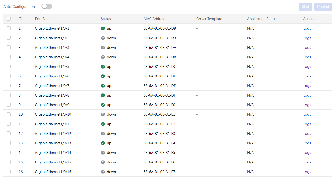
4. On the switch port list, select the switch ports to which you want to bind a server template, and then click Bind.
5. In the dialog box that opens, select the server template you want to bind to the selected switch ports, and then click OK.
Figure 98 Binding a server template to the selected switch ports
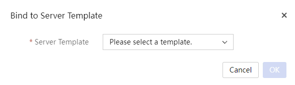
6. Turn on the Auto-Configuration toggle switch to enable the auto-configuration feature.
7. To remove the server template bindings for some switch ports, select the ports, and then click Unbind. In the confirmation dialog box that opens, click OK.
8. To view the server template application logs for a switch port, click the Logs link in the Actions column for the switch port.
Delete a switch
1. In the navigation pane, select Menu > Devices > Switches.
2. Click Delete in the Actions column for the switch that you want to delete. In the dialog box that opens, click OK.
Update information of a switch
About this task
You can update the username and password of a switch in UniSystem, so that the username and password are consistent with those of the switch and the switch can pass authentication.
Procedure
1. In the navigation pane, select Menu > Devices > Switches.
2. Click Edit in the Actions column for the switch that you want to edit.
3. Enter related information and click OK.
Search for switches
About this task
Perform this task to search for switches by name, IP, and other information.
Procedure
1. In the navigation pane, select Menu > Devices > Switches.
2. In the search area, select the search criterion and enter the search keyword. Available search criteria include device name, IP address, connection state, CPU usage, and memory usage.
View the cabinet details
1. In the navigation pane, select Menu > Devices > Switches.
2. Click the cabinet name link in the Node Location column. View the cabinent details.
View switch details
View the summary, card, port, and interface information of a switch
About this task
Perform this task to access the Switch Details page. The page provides the following tabs:
· Summary—Displays the basic information of the switch, including the device name, model, version, and management IP address.
· Cards—Displays information about the cards on the switch, including the card name, model, status, CPU usage, and memory usage.
· Ports—Displays information about the physical Ethernet and FC ports on the switch. For each physical port, this tab displays its PVID, link type, MAC address, traffic statistics, and peer end information.
· Interfaces—Displays information about the logical interfaces on the cards of the switch. Supported logical interface types include Layer 2/Layer 3 aggregate interfaces, VLAN interfaces, Loopback interfaces, null interfaces, InLoopback interfaces, Register-Tunnel interfaces, VFC interfaces, and HDLC link bundle interfaces. For each interface, this tab displays its name, status, IP address, interface type, and other information.
Procedure
1. In the navigation pane, select Menu > Devices > Switches.
2. Click the device name of a switch to enter the details page.
3. Click the Summary, Cards, Ports, or Interfaces tab to view information corresponding information about the switch.
Figure 99 Switch Details page
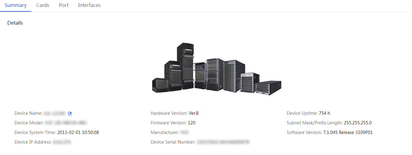
4. (Optional.) To rename the switch, click the Rename icon ![]() next to the
device name on the Summary tab. In the dialog box
that opens, enter the new device name, and then click OK.
next to the
device name on the Summary tab. In the dialog box
that opens, enter the new device name, and then click OK.
View the traffic statistics of a port or interface
About this task
Perform this task to view the traffic statistics of a physical port or logical interface on a switch card, such as the numbers of packets sent and received, and the packet drop statistics.
Procedure
1. In the navigation pane, select Menu > Devices > Switches.
2. Click the device name of a switch to enter the details page.
3. Click the Ports or Interfaces tab, and then click Traffic Details in the Actions column for a port or interface.
|
|
NOTE: For interfaces on switches, you can view detailed traffic statistics about only aggregate interfaces. |
4. Click Last Statistics Polling Interval to view traffic statistics collected for the port or interface during the last polling interval. The default polling interval is 300 seconds.
Figure 100 Interface traffic statistics
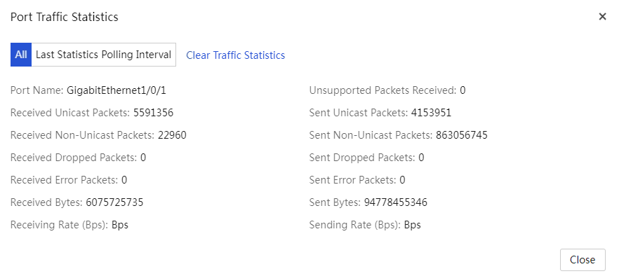
Manage switch labels
Perform this task to add, delete, and edit switch labels.
Add a switch label
You can assign labels to switches for ease of management as needed. You can add up to 1000 switch labels.
Procedure
1. In the navigation pane, select Menu > Devices > Switches.
2. Click Manage Labels, and then select Create Label.
3. In the dialog box that opens, enter related information and click OK.
Figure 101 Adding a switch label
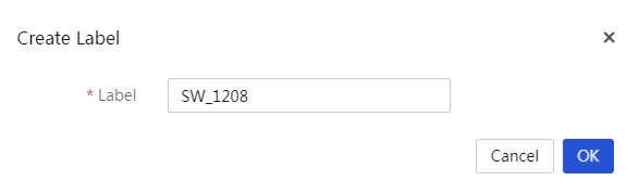
Edit a switch label
1. In the navigation pane, select Menu > Devices > Switches.
2. Click Manage Labels, and then select Edit Label.
3. In the Basic Info area, select the label you want to edit and enter the new label name.
4. In the Device List area, click Add to select the devices to which you want to assign this label.
5. To remove the label from one or more devices, select the devices on the device list, and then click Delete.
6. Click OK.
Figure 102 Editing a switch label
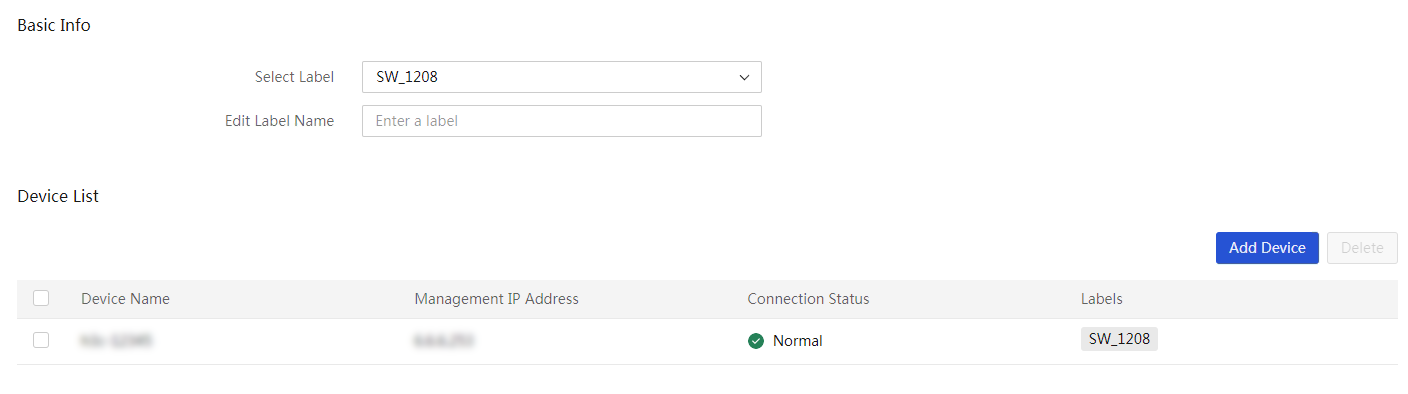
Delete switch labels
1. In the navigation pane, select Menu > Devices > Switches.
2. Click Labels. Click Delete Label.
3. In the dialog box that opens, select the labels to delete and click OK.
Infrastructure
UniSystem supports managing the following types of infrastructure: distributed Cooling Distribution Units (CDUs), centralized CDUs, immersion-cooled CDUs, environmental monitoring hosts, rear door heat exchangers, and other devices using Modbus TCP as the northbound interface.
· Through the preset monitoring templates CDU5204 (distributed), ColdPlateCDU (centralized), and ImmersionCDU (immersion-cooling) provided by UniSystem, you can add a device to UniSystem by entering the device IP address and name.
· UniSystem also supports adding custom monitoring templates to manage environmental monitoring hosts, rear door heat exchangers, and other devices using Modbus TCP as the northbound interface. For more information about adding a custom monitoring template, see "Manage custom monitoring templates."
Manage infrastructure
Restrictions and guidelines
The device name is case-sensitive. Make sure the device name is unique in the infrastructure list, and make sure devices in the list have different IP address and port number combinations. If the device name or IP address and port number combination already exists, the device adding operation fails.
You cannot add a device if the corresponding infrastructure has been added to cabinent management.
Procedure
1. In the navigation pane, select Menu > Devices > Manage Infrastructure > Infrastructure.
2. Click Add Device. In the dialog box that opens, perform the following tasks:
a. Enter the device name.
b. Select a template. The built-in CDU5204 template is applicable only to the CDU-AAVID-377431-60KW device of the Aavid vendor.
c. Enter the IP address of the device management port.
d. Select the scope.
e. (Optional.) Select the corresponding data center and equipment room, and enter the description.
3. Click OK.
Figure 103 Adding a CDU device
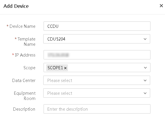
4. After successfully adding devices, you can view the summary status and details of the infrastructure in the CDU device list, including device name, manufacturer, model, IP address, port number, health status, and power status, as shown in Figure 104.
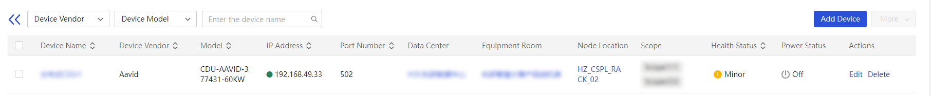
5. (Optional.) To edit or delete a device, click Edit or Delete in the Actions column for the device.
6. (Optional.) To filter devices in the list, select the device vendor and model, and enter the device name keywords.
Parameters
· Device Name: You must enter the device name when adding a device. The name is a case-sensitive string of 1 to 30 characters. Only Chinese characters, digits, letters, underscores (_), and hyphens (-) are supported.
· Template Name: Monitoring template bound to the device.
· IP Address: IP address of the management port on the device. Only IPv4 addresses are supported.
· Scope: Scope to which the device to be added belongs.
· Data Center: Data center to which the device belongs. This field is optional.
· Equipment Room: Equipment room in which the device resides. If you specify the equipment room, you must also specify the corresponding data center.
· Description: Description of the device. The description cannot exceed 64 characters in length and cannot start or end with a space. Only Chinese characters, digits, letters, underscores (_), and spaces are supported. This field is optional.
View infrastructure details
Perform this task to view the detailed information about infrastructure devices, including an overview diagram, general information, and alarm statistics, and perform cabinet management.
View the overall infrastructure status
1. In the navigation pane, select Menu > Devices > Manage Infrastructure > Infrastructure.
2. Click the name link of the target device to view its details, as shown in Figure 105.
Figure 105 Infrastructure details
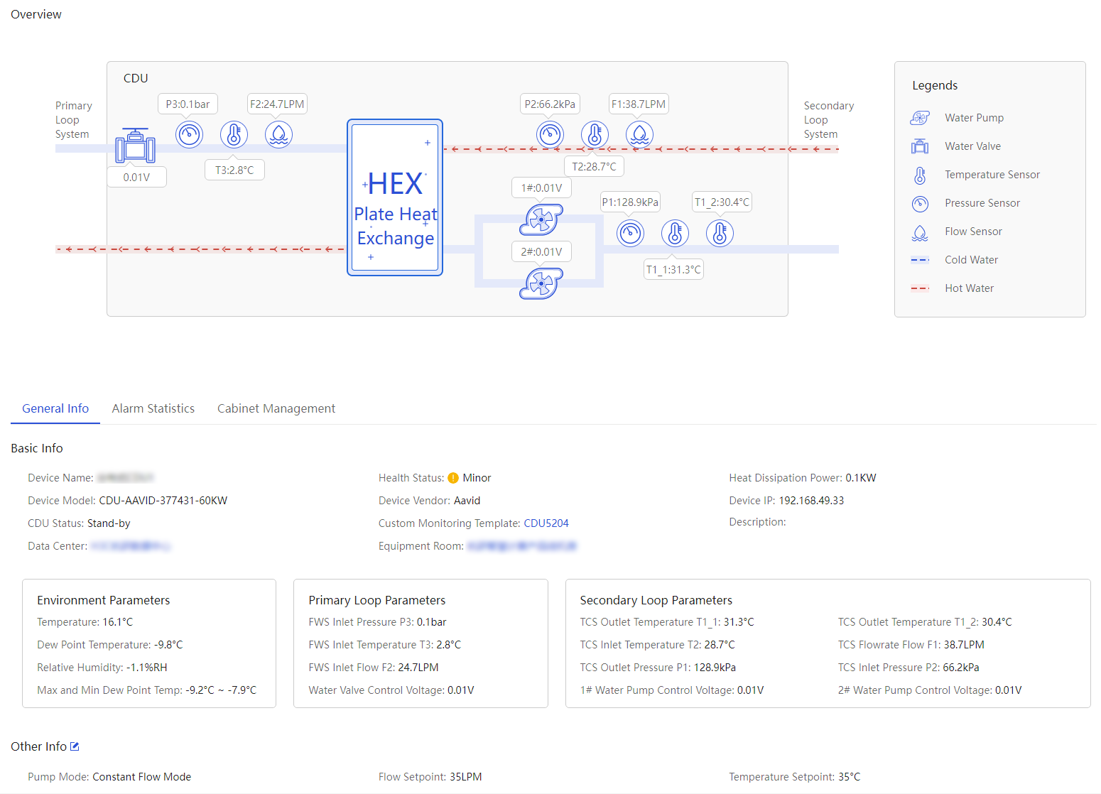
3. View the overview diagram and general information.
View infrastructure alarm statistics
1. In the navigation pane, select Menu > Devices > Manage Infrastructure > Infrastructure.
2. Click the name link of the target device to view its details.
3. Click the Alarm Statistics tab to view alarm statistics information.
4. To clear alarm statistics, click Alarm Clear.
Cabinet management
1. In the navigation pane, select Menu > Devices > Manage Infrastructure > Infrastructure.
2. Click the name link of the target device to view its details.
3. Click the Cabinet Management tab. You can view the list of cabinets associated with the infrastructure.
4. To view the details about a cabinet, click the cabinet name link.
5. To add devices to a cabinet, click Bind Cabinet. The operation method varies by device type.
¡ For centralized CDUs and immersion-cooled CDUs, a confirmation dialog box appears. Select the target cabinets and then click OK.
¡ For
distributed CDUs, the cabinet details page opens. Click the ![]() button
in the cabinet view, enter CDU information in the dialog box that opens, and
then click OK.
button
in the cabinet view, enter CDU information in the dialog box that opens, and
then click OK.
6. To remove devices from a cabinet, click Unbind. The unbind operation varies by device type.
¡ For centralized CDU and immersion-cooled CDU, a confirmation dialog box appears. Click OK in the dialog box.
¡ For distributed CDUs, the cabinet details page opens. Click Remove in the Actions column to remove the target device.
More options for an infrastructure device
UniSystem supports remote management of infrastructure devices in bulk, including controlling device power, water pumps, and temperature, and deleting devices in bulk.
Figure 106 Clicking More
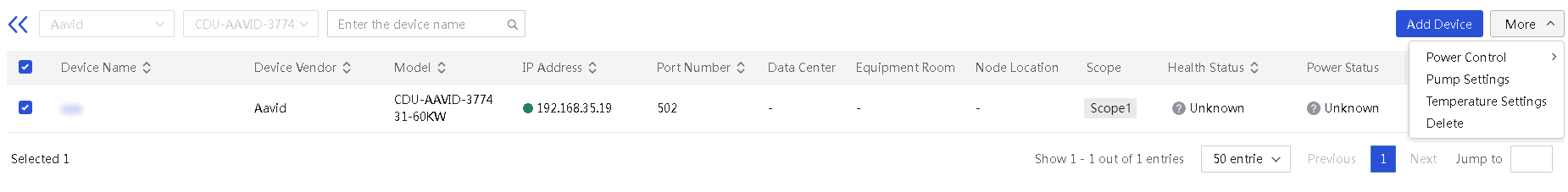
Perform power operations
This module allows you to remotely control the power status of infrastructure devices.
Restrictions and guidelines
To ensure the normal execution of power management operations, configure the PowerStatus, PowerOn, and PowerOff sensors in the custom monitoring template correctly under the guidance of technical support. These sensors are key to implementing power management functions.
Procedure
1. In the navigation pane, select Menu > Devices > Manage Infrastructure > Infrastructure.
2. Select the target devices, click More, select Power Control, and then click the power action.
Figure 107 Performing power operations
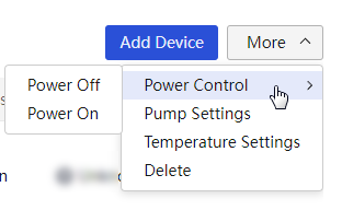
3. In the dialog box that opens, confirm the devices to be managed, select to agree to the user notice, and then click OK.
Configure pumps
This module allows you to remotely configure water pumps on infrastructure devices in bulk.
Restrictions and guidelines
Only the CDU-AAVID-377431-60KW device of the Aavid vendor supports configuring pumps.
Procedure
1. In the navigation pane, select Menu > Devices > Manage Infrastructure > Infrastructure.
2. Select the target devices, click More, and then click Pump Settings.
3. In the dialog box that opens, configure pump settings, and then click OK.
Figure 108 Configuring pumps
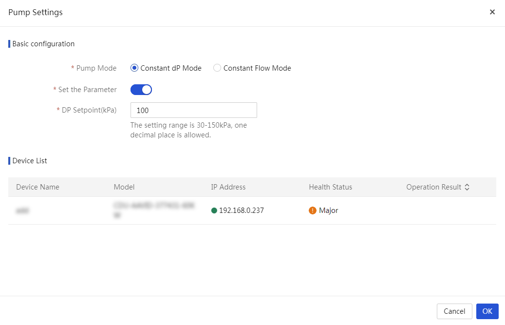
Configure temperature settings
This module allows you to remotely configure temperature settings for infrastructure devices in bulk.
Restrictions and guidelines
Only the CDU-AAVID-377431-60KW device of the Aavid vendor supports configuring temperature settings.
Procedure
1. In the navigation pane, select Menu > Devices > Manage Infrastructure > Infrastructure.
2. Select the target devices, click More, and then click Temperature Settings.
3. In the dialog box that opens, set the temperature setpoint, and then click OK.
Figure 109 Configuring temperature settings
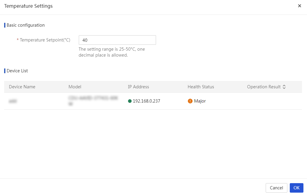
Configure the leakage handling strategy
This function configures the leakage handling strategy for dynamic environment hosts. When a monitored cabinet triggers a leakage alarm, UniSystem executes the action based on the configured strategy. If auto shutdown is selected, UniSystem will automatically close the host's solenoid valve to prevent leakage spread or equipment damage.
Procedure
1. In the navigation pane, select Menu > Devices > Manage Infrastructure > Infrastructure.
2. Select the target devices, click More, and then click Leakage Handling Strategy.
Figure 110 Leakage handling strategy
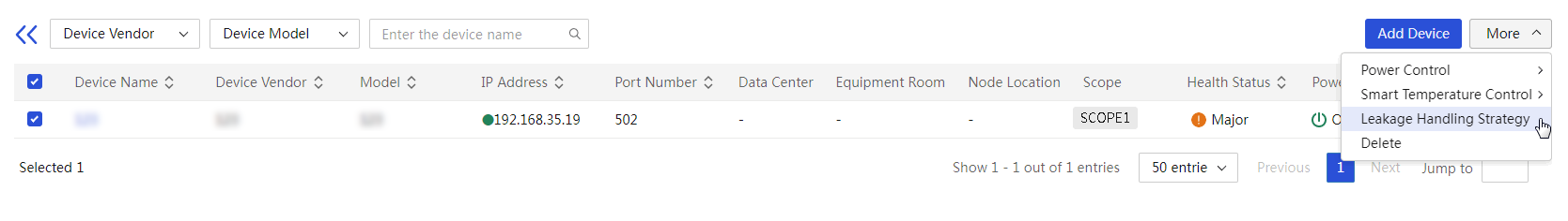
3. In the dialog box that opens, select the solenoid valve strategy.
Figure 111 Solenoid valve strategy
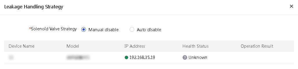
4. Click OK.
Configure smart temperature control
|
|
NOTE: Only H3C UniServer R5500 G7 cold plate-based server supports this feature. |
Perform this task to enable or disable smart temperature control of an environmental monitoring system. With this feature enabled, when the temperature of a cold plate-based server in the same cabinet as the system changes, UniSystem intelligently adjusts the opening degree of the valve controlled by the system to save liquid cooling power consumption.
Prerequisites
Before enabling this function, configure the solenoid valve opening sensor in the monitoring template for the environmental monitoring host. For more information, see "Manage custom monitoring templates."
Procedure
1. In the navigation pane, select Menu > Devices > Manage Infrastructure > Infrastructure.
2. Select the target devices, click More, and then click Smart Temperature Control.
Figure 112 Configuring smart temperature control
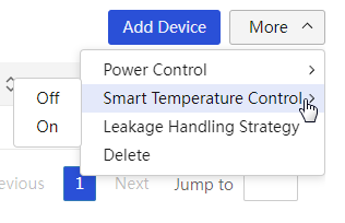
3. Click OK.
Delete a device
1. In the navigation pane, select Menu > Devices > Manage Infrastructure > Infrastructure.
2. Select the target devices, click More, and then click Delete.
3. In the confirmation dialog box that opens, click OK.
Figure 113 Deleting a device
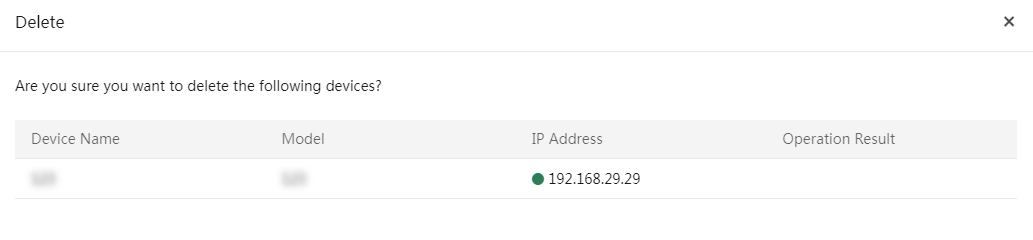
Manage custom monitoring templates
Procedure
1. In the navigation pane, select Menu > Devices > Manage Infrastructure > Custom Monitoring Template.
2. Click Add Monitoring Template. Then, configure basic information and sensor settings.
3. (Optional.) Click Download Template to download the custom monitoring template (.xlsx or .xls format). Fill in the template and then upload it.
Figure 114 Adding a custom monitoring template
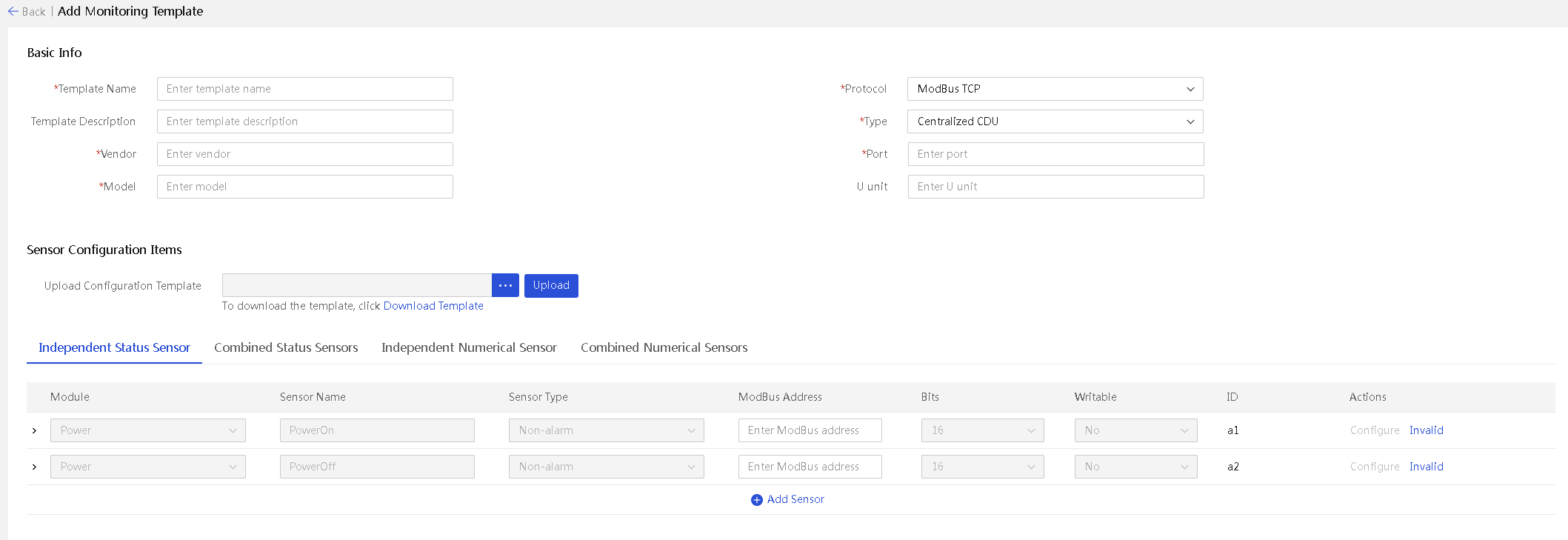
4. Click OK. You can then view information about the successfully added template in the custom monitoring template list.
Figure 115 Custom monitoring template list
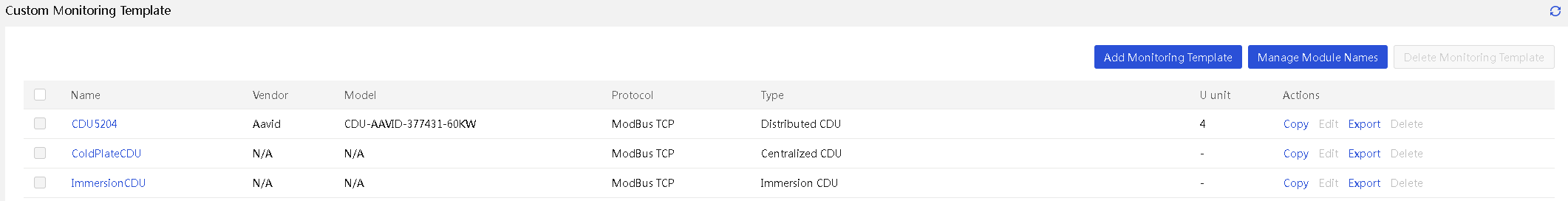
5. To view the details about a monitoring template, click the name link for the template.
Figure 116 Custom monitoring template
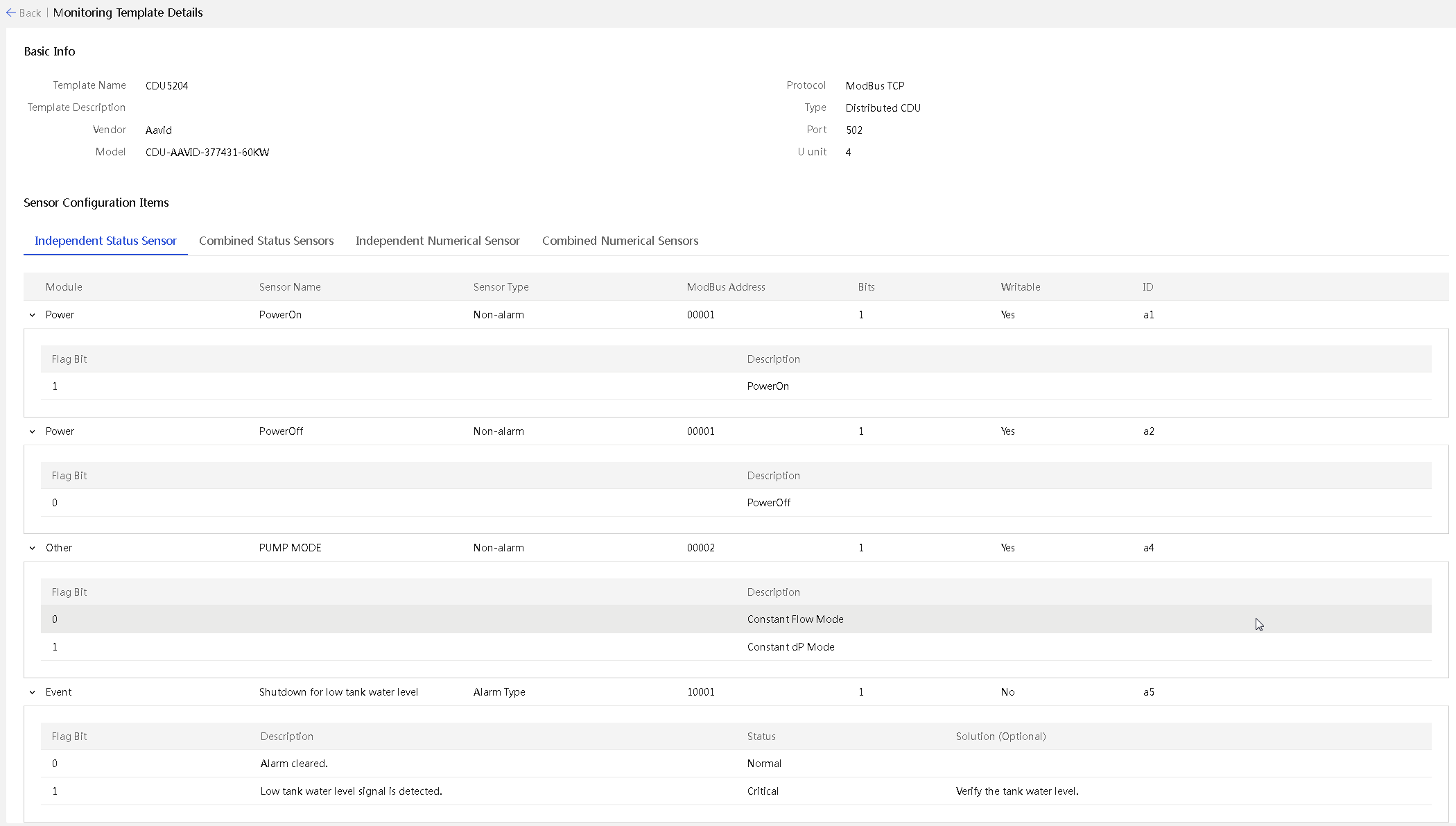
6. To manage module names, click Manage Module Names. In the dialog box that opens, enter the required information, and then click OK.
Figure 117 Module name management
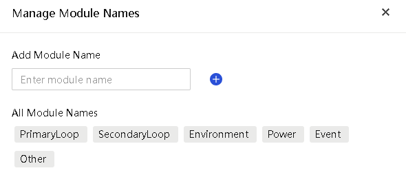
7. To create a template inheriting the configuration of an existing template, or to edit or delete a template, click Inherit Create, Edit, or Delete in the Actions column.
Parameters
Basic information
· Template Name: Name of the monitoring template. The name is a case-sensitive string of 1 to 30 characters. Only Chinese characters, digits, letters, and underscores (_) are supported.
· Template Description: Description of the monitoring template, a case-sensitive string of 0 to 30 characters. The string cannot start or end with a space. Only Chinese characters, digits, letters, underscores (_), and spaces are supported.
· Vendor: Manufacturer of compatible devices, a case-sensitive string of 1 to 30 characters. Only Chinese characters, digits, letters, and underscores (_) are supported.
· Model: Model of compatible devices, a case-sensitive string of 1 to 30 characters. Only Chinese characters, digits, letters, underscores (_), hyphens (-), and dots (.) are supported.
· Protocol: Protocol of compatible devices. Only the ModBus TCP protocol is supported.
· Type: Type of compatible devices. Options include centralized CDU, distributed CDU, immersion CDU, rear door heat exchanger, and environmental monitoring host.
· Port: Port number of compatible devices.
· U Unit: U position of compatible devices, an integer in the range of 1 to 100. This field is required for distributed CDUs and environmental monitoring hosts.
Independent status sensors
· Module: Module to which the sensor belongs. Make sure the module has been created. In custom device details, all sensors, except for alarm and power supply sensors, will be categorized under their respective modules.
· Sensor Name: Name of the sensor to be added, a case-sensitive string of 1 to 100 characters. This field is required.
· Sensor Type: Type of the sensor, alarm or non-alarm.
· ModBus Address: ModBus address of the sensor to be added. Both 5-digit and 6-digit ModBus addresses are supported.
· The 5-digit address must be in the range of 00001-09999, 10001-19999, 30001-39999, or 40001-49999.
· The 6-digit address must be in the range of 000001-065536, 100001-165536, 300001-365536, or 400001-465536.
· Bits: Bit number of the sensor to be added, where 1 bit represents a coil and 16 bits represent a register. Determine the number of bits for the sensor based on the correct ModBus address.
· Writable: Whether the sensor is writable.
· ID: ID corresponding to the sensor (used for custom expression calculation).
· Valid Bits: When you select a 16-bit register in the Bits field, you can either select all bits or select a specific bit from 0 to 15 as the valid bits.
· Flag Bit: Actual reading represented by the selected valid bits. Only a hexadecimal string and the string other is supported. Flag bits must not be duplicated. When you set the flag bit value to other, it indicates that if the result does not match any other flag bits, the result will be classified under the other flag bit. Additionally, the other flag bit cannot be selected in the sensor settings on the device details page.
· Description: Description of the flag bit to be added, a string in the range of 1 to 200 characters. This field is required.
· State: State of the flag bit to be added. Only normal, minor, major, and critical are supported. This field is available only for alarm sensors.
· Solution: Solution for condition represented by the flag bit to be added, a string of 0 to 200 characters. This field is available only for alarm sensors and cannot contain only spaces.
· Combined status sensors
· Module: Module to which the sensor belongs. Make sure the module has been created. In custom device details, all sensors will be categorized under their respective modules.
· Sensor Name: Name of the sensor to be added, a case-sensitive string of 1 to 100 characters. This field is required.
· Flag Bit: Result corresponding to the custom expression. Only a hexadecimal string and the string other is supported. Flag bits must not be duplicated. When you set the flag bit value to other, it indicates that if the result does not match any other flag bits, the result will be classified under the other flag bit. Additionally, the other flag bit cannot be selected in the sensor settings on the device details page.
· State: State of the sensor to be added. Only normal, minor, major, and critical are supported.
· Description: Description of the sensor to be added, a string in the range of 1 to 200 characters. This field is required.
· Solution: Solution for condition represented by the sensor to be added, a string of 0 to 200 characters. This field cannot contain only spaces.
· Custom Expression: Expressions for the ID and numerical combination of different state alarm sensors. Only operators () ~ + - * / & | >> << are supported. The expression cannot exceed 120 characters and can contain a maximum of 32 sensor IDs and digits. When you configure custom expressions for Combined status sensors, you can only select status sensors that have already been configured.
Independent numeric sensors
· Module: Module to which the sensor belongs. Make sure the module has been created. In custom device details, all sensors will be categorized under their respective modules.
· Sensor Name: Name of the sensor to be added, a case-sensitive string of 1 to 100 characters. This field is required.
· ModBus Address: ModBus address of the sensor to be added. Both 5-digit and 6-digit addresses are supported. The 5-digit address must be in the range of 30001-39999 or 40001-49999. The 6-digit address must be in the range of 300001-365536 or 400001-465536.
· Bits: Number of bits for the sensor to be added. 16 bits indicate that one register represents one independent numeric sensor, and 32 bits indicate that two registers represent one independent numeric sensor. When the ModBus address is 39999, 49999, 365536, or 465536, you cannot set the Bits to 32.
· Value Type: Value type of the sensor to be added. Both integer and floating point types are supported. The floating point type is available only when the Bits field is set to 32. When the Bits field is set to 16, the value type is fixed to integer.
· With Symbol: Whether the value of the sensor to be added is a signed number. This field is available only when the Value Type field is set to Integer.
· Decimal Precision: Number of decimal places in values of the sensor. Up to 5 decimal places are supported. This field is available only when the Bits field is set to 32 and the Value Type is floating point.
· High Byte Position: Indicates which register's value is in the high position when the Bits field is 32 (meaning two 16-bit registers represent one sensor).
· Scale Factor: Multiplier to apply to the value read from the register, in the range of 0 (excluded) to 100 (included). Up to 5 decimal places are supported.
· Unit: Unit for the sensor to be added, a string in the range of 0 to 10 characters. The string cannot contain only spaces.
· Writable: Whether digits can be written to the ModBus address of the sensor. This field is available only when the ModBus address is in the range of 40001-49999 or 400001-465536.
· Limit Range: Upper and lower limits for writable values when the sensor is set to writable. The default is the upper and lower limits supported by the value type. Custom values and scientific notation are supported.
Composite numerical sensors
· Module: Module to which the sensor belongs. Make sure the module has been created. In custom device details, all sensors will be categorized under their respective modules.
· Sensor Name: Name of the sensor to be added, a case-sensitive string of 1 to 100 characters. This field is required.
· Unit: Unit for the sensor to be added, a string in the range of 0 to 10 characters. The string cannot contain only spaces.
· Decimal Precision: Number of decimal places in values of the sensor. Up to 5 decimal places are supported. This field is available only when the Bits field is set to 32 and the Value Type is floating point.
· Custom Expression: Expression combining the independent sensor value and the composite sensor IDs prior to this sensor. Only operators ( ) + - * / are supported. The expression cannot exceed 120 characters and can contain a maximum of 32 sensor IDs and digits. When you configure custom expressions for composite numerical sensors, you can only select numerical sensors that have already been configured.
Restrictions and guidelines
· The system comes with three default templates: CDU5204, ColdPlateCDU, and ImmersionCDU, which cannot be edited or deleted.
· You cannot add a template with a duplicate name.
· You cannot add templates with the same vendor and model.
· You cannot add sensors with the same name within a template.
· The PowerOn and PowerOff sensors (independent status sensors for power supply) are case-insensitive. Since these sensors need to be displayed in the custom device list and be operated, you cannot bind other sensors to this name. The sensors can only operate as independent status sensors. You must configure whether the sensors are active. If the sensors are active, you must also enter the sensor values. The ModBus addresses for PowerOn and PowerOff sensors must be in the range of 00001-09999, 40001-49999, 000001-065536, or 400001-465536. The flag bit cannot be other.
· The PowerStatus sensor (Combined status sensor for power supply) is case-insensitive and can only be used as a combined status sensor. You must configure whether the sensor is active. If the sensor is active, you must also enter the custom expression and flag bit for the sensor.
· When you add a monitoring template for the environmental monitoring host device type, the SolenoidOff (solenoid valve sensor), LeakageLiquid (leakage alarm sensor) sensors, and SolenoidValue (solenoid valve sensor) automatically appear as reserved sensors. To avoid template adding failures, you must configure the sensor-related parameters when the sensor is active.
¡ SolenoidOff sensor: The default module is other, with a fixed sensor name that cannot be shared by other sensors. The default sensor type is non-editable non-alarm sensor. The ModBus address of the sensor must be in the range of 40001-49999 or 400001-465536. The sensor supports configuring two flag bits. By default, the flag bit for description SolenoidOff is set to 0 and the flag bit for description SolenoidOn is set to 1.
¡ LeakageLiquid sensor: Dedicated monitoring template for environmental monitoring hosts. The sensor belongs to the alarm module by default and has a fixed name. Other sensors cannot use the same name. The default type is alarm and the ModBus address of the sensor must be in the range of 40001-49999 or 400001-465536. If you select a bit from 0 to 15 as the valid bit, the flag bits cannot be set to other. You must set the flag bits to 1 and 0, where 0 represents leakage alarm cleared and 1 represents leakage alarm triggered. If you select all bits as the valid bits, the flag bits can be 0, 1, 2, and 3, where 0 represents leakage alarm cleared and the other three values represent leakage alarm triggered. The leakage handling strategy takes effect only when the LeakageLiquid sensor is valid, and either of the SolenoidOff or SolenoidValue sensor or both are valid. When the LeakageLiquid sensor detects a leakage, it closes the solenoid valve using either the SolenoidOff or SolenoidValue sensor, according to the leakage handling strategy.
¡ SolenoidValue sensor: Dedicated monitoring template for environmental monitoring hosts. The default module is other, with a fixed sensor name that cannot be shared by other sensors. Other sensors cannot use the same name. The default type is non-alarm sensor, with a fixed coefficient of 1 and a value range limited to 0-100. Other parameters can be configured to align with the environmental monitoring host settings. The ModBus address of the sensor must be in the range of 40001-49999 or 400001-465536. For the smart temperature control policy to take effect, make sure that the sensor is valid and properly configured.
· To set the state of an independent status sensor to writable, make sure the ModBus address of the address cannot be in the range of 10001-19999, 30001-39999, 100001-165536, or 300001-365536.
· For an independent status sensor, you can set the flag bit to other only when the Bits field is 16. You can set up to one other flag bit.
· An independent status sensor requires a minimum one flag bit. When only one flag bit exists, its value cannot be other.
· When the ModBus address of an independent status sensor is in the range of 00001-09999, 10001-19999, 000001-065536, or 100001-165536, the Bits field is 1. When the ModBus address is in the range of 30001-39999, 40001-49999, 300001-365536, or 400001-465536, the Bits field is 16.
· For sensors other than PowerOn and PowerOff, the ModBus address of an independent status sensor must be unique if it is in the range of 00001-09999, 10001-19999, 000001-065536, or 100001-165536. The ModBus address and valid bit combination must be unique if the address is in the range of 30001-39999, 40001-49999, 300001-365536, or 400001-465536.
· The ModBus address of an independent status sensor must not duplicate the ModBus address of an independent numerical sensor.
· If the Bits of an independent status sensor is 1, the flag bit can only be set to 0 or 1.
· If the Bits of an independent status sensor is 16, you can set the flat bit to other or a hexadecimal string ranging from 0 to FFFF.
· The flag bit of an independent status sensor must be unique.
· When the type of an independent status sensor is non-alarm, the sensor description must be unique.
· The sensor type, ModBus address, and Bits of an independent status sensor are closely related to the sensor configuration. Changing the sensor type, Bits, or first digit of the ModBus address automatically clears the current configuration.
· When the module of an independent sensor is alarm, the sensor module defaults to the alarm type.
· The combined status sensors have a strict sequence. Sensors configured later can select those configured earlier, but sensors configured earlier cannot select those configured later.
· The operators supported by combined status sensors include () + - * / & | >> <<.
· The composite numerical sensors have a strict sequence. Sensors configured later can select those configured earlier, but sensors configured earlier cannot select those configured later.
· The operators supported by composite numerical sensors include () + - * /.
· Once bound to a combined status sensor, the corresponding sub-status sensors in the expression cannot be deleted.
· Once bound to a composite numerical sensor, the corresponding sub-numerical sensors in the expression cannot be deleted.
Data center management
The data center module allows users to manage supported devices in a unified manner, including servers, switches, and liquid cooling equipment (infrastructure). It enables users to view the health state and temperature state of managed devices collectively. Users can view the occupancy and power supply status of cabinets to allocate space reasonably and detect power supply risks in time.
View data center information
View data center summary
1. In the navigation pane, select Menu > Devices > Data Center Management > Data Center List.
2. View summary information about data centers.
Figure 118 Viewing data center summary
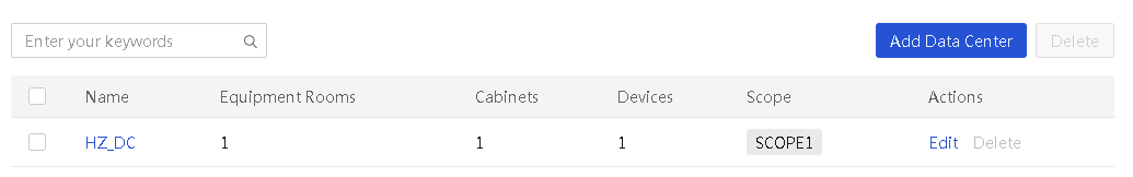
View data center details
1. In the navigation pane, select Menu > Devices > Data Center Management > Data Center List.
2. To view detailed information for a data center, click the data center name.
Figure 119 Viewing data center details
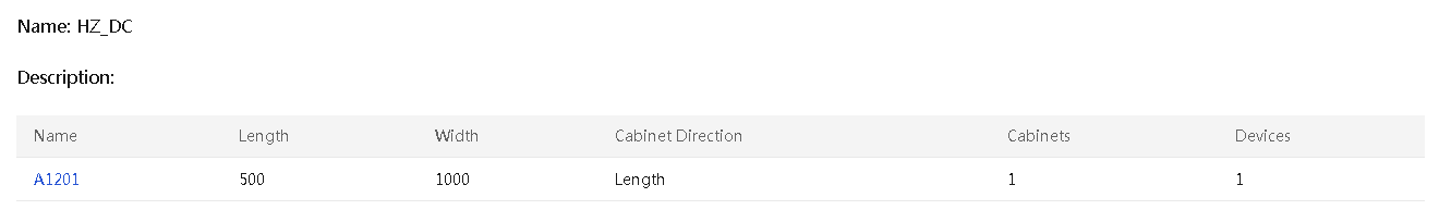
Manage data centers
Add a data center
Restrictions and guidelines
The data center name must be unique.
Procedure
1. In the navigation pane, select Menu > Devices > Data Center Management > Data Center List.
2. Click Add Data Center. In the dialog box that opens, configure related parameters and click OK.
Figure 120 Adding a data center
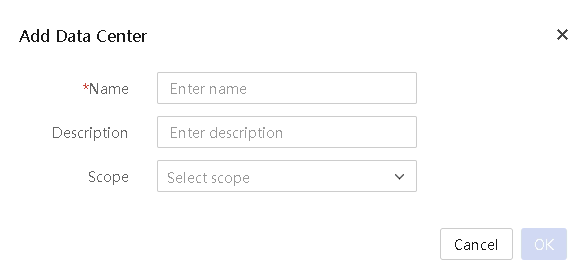
Edit a data center
Restrictions and guidelines
The data center name must be unique.
Procedure
1. In the navigation pane, select Menu > Devices > Data Center Management > Data Center List.
2. Click Edit in the Actions column for the data center. In the dialog box that opens, edit information and then click OK.
Delete data centers
Restrictions and guidelines
If equipment rooms have been added to a data center, you cannot delete the data center directly. Remove all equipment rooms from the data center and perform the delete operation again.
Procedure
1. In the navigation pane, select Menu > Devices > Data Center Management > Data Center List.
2. To delete data centers in batch, select target data centers and click Delete. In the dialog box that opens, click OK. To delete a data center, click Delete in the Actions column for the data center.
Figure 121 Deleting data centers
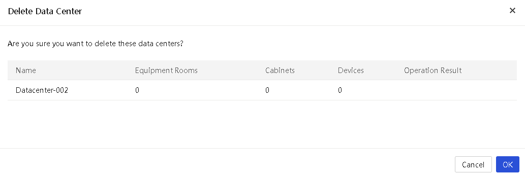
View equipment room information
View equipment room summary
Procedure
1. In the navigation pane, select Menu > Devices > Data Center Management > Equipment Room.
2. View summary information about equipment rooms.
Figure 122 Viewing equipment room summary
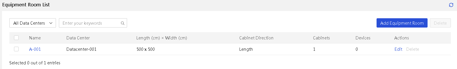
View equipment room details
Procedure
1. In the navigation pane, select Menu > Devices > Data Center Management > Equipment Room.
2. To view detailed information for an equipment room, click the equipment room name.
You can also click the equipment room name on the Data Center Details page of the data center to which the equipment room belongs to view the equipment room details.
View the liquid cooling flow information
This feature allows viewing information about the liquid cooling flow between the data center infrastructure and cabinets. The liquid cooling flow view uses a topology map to depict the associations between the infrastructure and cabinets, as well as information related to primary and secondary side temperature and pressure sensors within the infrastructure.
Restrictions and guidelines
Only the infrastructure associated with cabinets and managed by UniSystem's built-in custom monitoring templates supports the topology map feature.
Procedure
1. In the navigation pane, select Menu > Devices > Data Center Management > Equipment Room.
2. Click the name link of the target equipment room and view the detailed information.
3. Click the Liquid Cooling Flow tab and view the information.
4. (Optional.) To view detailed information about a cabinent or infrastructure, click the cabinet or infrastructure name in the flow topology map.
5. (Optional.) To zoom in, zoom out, or reset
the view to its original scale, click the corresponding icon ![]() in the
top left corner.
in the
top left corner.
6. (Optional.) To view sensor information, hover over the pipe icons in the flow topology map.
7. (Optional.) To view the full infrastructure name, model, or vendor information, hover over the name, model, or vendor of infrastructure in the flow topology map.
8. (Optional.) If you hover over the secondary side pipe icon, infrastructure, or cabinet, the secondary side pipe will be highlighted.
Manage equipment rooms
Add an equipment room
Restrictions and guidelines
The equipment room name must be unique in a data center.
Procedure
1. In the navigation pane, select Menu > Devices > Data Center Management > Equipment Room.
2. Click Add Equipment Room. In the dialog box that opens, configure equipment room information and then click OK.
Figure 123 Adding an equipment room
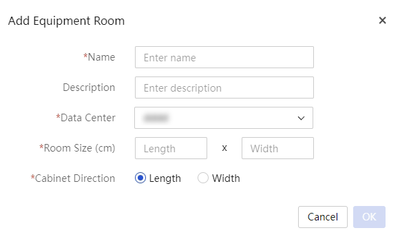
Edit an equipment room
Restrictions and guidelines
· The equipment room name must be unique in a data center.
· If you want to edit the length or width of an equipment room, make sure the equipment room after the editing can accommodate the added cabinets. Otherwise, you cannot edit the equipment room size.
Procedure
1. In the navigation pane, select Menu > Devices > Data Center Management > Equipment Room.
2. Click Edit in the Actions column for the equipment room. In the dialog box that opens, edit room information and then click OK.
Delete equipment rooms
Restrictions and guidelines
If cabinets have been added to an equipment room, you cannot delete the equipment room directly. Remove all cabinets from the equipment room and perform the delete operation again.
Procedure
1. In the navigation pane, select Menu > Devices > Data Center Management > Equipment Room.
2. To delete equipment rooms in batch, select target equipment rooms and click Delete. In the dialog box that opens, click OK. To delete an equipment room, click Delete in the Actions column for the equipment room.
Figure 124 Deleting equipment rooms
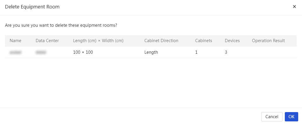
Parameters
· Name: Equipment room name.
· Description: Equipment room description. This field is optional.
· Data Center: Data center to which the equipment room belongs.
· Room Size (cm): Length and width of the equipment room.
· Cabinet Direction: Cabinet orientation in the equipment room, either lengthwise or widthwise.
View cabinet information
Restrictions and guidelines
When you change the IP address of a cabinet, make sure the new IP address does not conflict with the IP of similar devices. If the IP addresses conflict, the device might be marked as abnormal, which can cause abnormal power and power consumption data. If abnormal devices exist, remove and re-add them.
Procedure
1. In the navigation pane, select Menu > Devices > Data Center Management > Cabinet.
2. View summary information about cabinets.
3. To view the detailed information about a cabinet, click the cabinet name.
You can also view cabinet details by clicking the cabinet name on the equipment room details page.
4. (Optional.) To view information about associated infrastructure, click the Associated Infrastructure tab.
Manage cabinets
Add a cabinet
Restrictions and guidelines
· Cabinet space information contains the cabinet coordinates and size. The data center will verify cabinet space information to see whether the space of a cabinet conflicts with other cabinets and whether the space is within the permitted range. Otherwise, you cannot perform the add or edit operation.
· The cabinet name must be unique in an equipment room.
Procedure
1. In the navigation pane, select Menu > Devices > Data Center Management > Cabinet.
2. Click Add Cabinet. In the dialog box that opens, configure related parameters and click OK.
Figure 125 Adding a cabinet
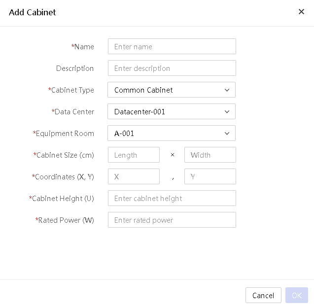
Edit a cabinet
Restrictions and guidelines
· Cabinet space information contains the cabinet coordinate and size. The data center will verify cabinet space information to see whether the space of a cabinet conflicts with other cabinets and whether the space is within the permitted range. Otherwise, you cannot perform the add or edit operation.
· You cannot edit a cabinet if a power capping task is running on the cabinet.
· If you want to edit the rated power of a cabinet, make sure the new rated power cannot be smaller than the value of G6 server number*150+total non-G6 sever reserved power. Otherwise, you cannot edit the cabinet.
· If you want to edit the height of a cabinet, makes sure that the new height satisfy the height requirement of managed servers on the cabinet. Otherwise, you cannot edit the cabinet height.
· Before modifying the cabinet type, make sure no devices exist in the cabinet. If a device exists in the cabinet, the modification fails.
Procedure
1. In the navigation pane, select Menu > Devices > Data Center Management > Cabinet.
2. Click Edit in the Actions column for the cabinet. In the dialog box that opens, edit the cabinet information and then click OK.
Delete cabinets
Restrictions and guidelines
You cannot delete a cabinet if a power capping task is running on the cabinet. If a cabinet has been associated with infrastructure or is performing power capping, you cannot delete the cabinet.
Procedure
1. In the navigation pane, select Menu > Devices > Data Center Management > Cabinet.
2. To delete cabinets in batch, select target cabinets and click Delete. In the dialog box that opens, click OK. To delete a cabinet, click Delete in the Actions column for the cabinet.
Figure 126 Deleting cabinets
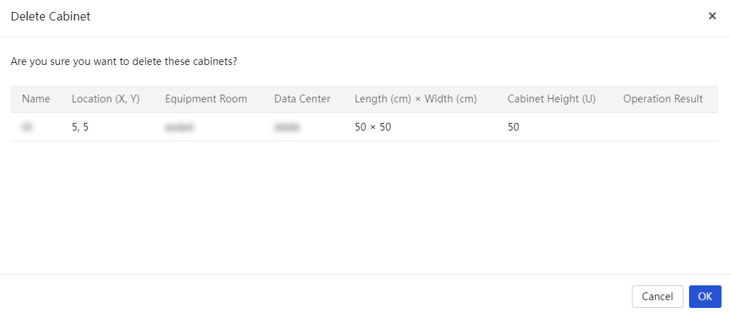
Parameters
· Name: Cabinet name.
· Description: Cabinet description. This field is optional.
· Cabinet Type: Cabinet type, including common and immersion (TANK).
· Data Center: Data center to which the cabinet belongs.
· Equipment Room: Equipment room to which the cabinet belongs.
· Cabinet Size (cm): Cabinet length and width.
· Coordinates (X, Y): Coordinates of the cabinet.
· Cabinet Height (U): Cabinet height.
· Rated Power (W): Cabinet rated power.
Manage devices
This feature allows users to add UniSystem-managed and custom devices to cabinets, including servers, switches, and infrastructure (only dynamic environment hosts and distributed CDUs are supported). After successful addition, you can remove devices as needed.
Add servers
Perform this task to add servers that are already in the server list or add custom severs to a cabinet.
Restrictions and guidelines
· You cannot add a new device if a power capping task is running on a cabinet.
· The available server list does not display offline servers, blade servers, and servers that have been added to a cabinet.
· The available device list does not display liquid-cooled devices that have an abnormal IP connection state or have been added to a cabinet.
· The available device list does not display switches with abnormal connection status or those that have been added to a cabinet.
Procedure
1. In the navigation pane, select Menu > Devices > Data Center Management > Cabinet.
2. Click a cabinet name to access its details page.
3. On the page that opens, select a spare bay in the cabinet. On the dialog box that opens, select Select Existing Devices or Add Custom Device for Add Device:
¡ To add an existing server, select a server from the available list, specify the reserved power for a non-G6 server, and click OK.
¡ To add a custom server, configure the server information and click OK.
Figure 127 Selecting existing devices
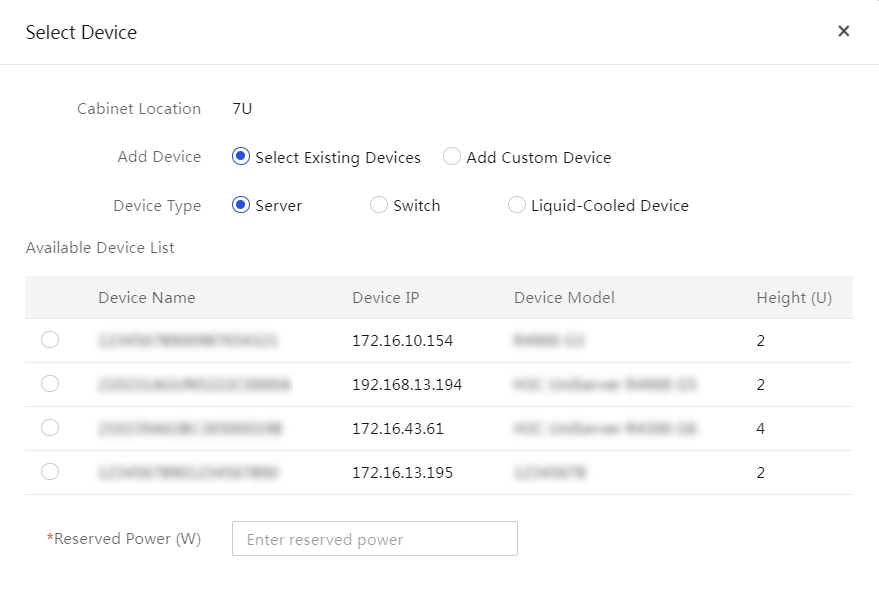
Figure 128 Adding Custom Device
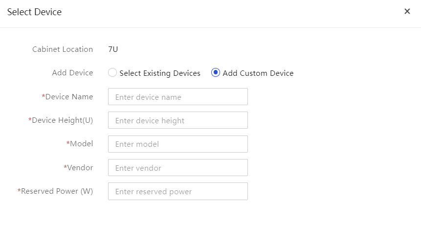
4. (Optional.) To remove devices, select the target devices, and then click Delete. In the confirmation dialog box that opens, click OK.
Manage templates
UniSystem offers comprehensive template management features, covering a variety of configuration types such as chassis, servers, and HDM/BIOS. This aids enterprises in achieving efficient resource configuration management.
· Unified management
Using a unified template for configuration management simplifies and centralizes the management of all configurations, significantly reducing configuration time and complexity, thereby shortening the device deployment cycle.
· Refined scope management
By dividing scopes based on dimensions such as departments or regions, configuration templates are categorized as resources into different scopes. Users can access and use only the corresponding templates according to their assigned roles and scopes. This enhances configuration efficiency and security.
|
|
NOTE: · To manage templates based on scopes, you must first configure the scopes. For more information, see "Scope management." · The value of All Resources represents all resources in the system, indicating that the user can manage all resources and are not limited by scopes. If the current user can manage all resources, the scople configuration is optional. |
Manage enclosure templates
From the Templates > Enclosure Templates page, you can add, copy, delete, edit, and view enclosure templates.
In an enclosure template, you can bind server templates to blade server slots in an enclosure. Then, you can apply the enclosure template to selected enclosures. For more information about applying enclosure templates, see "Apply enclosure templates."
View enclosure template information
About this task
Perform this task to view the enclosure template list and detailed information about an enclosure.
Procedure
1. In the navigation pane, select Menu > Templates > Enclosure Templates.
Figure 129 Enclosure template list

2. To view detailed information about an enclosure template, click the name of the template.
Add an enclosure template
Procedure
1. In the navigation pane, select Menu > Templates > Enclosure Templates.
2. Click Add.
3. In the Basic Info area, perform the following:
a. Enter the template name and description (optional).
b. Select the scope.
4. In the Blade Server-to-Template Bindings area, select the server template to bind to each blade server slot. For information about configuring a server template, see "Manage server templates."
5. Click OK.
Figure 130 Adding a server template
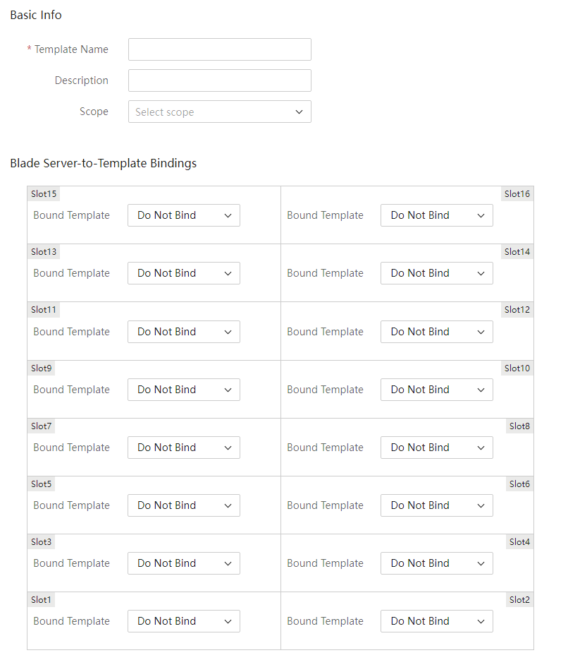
Delete enclosure templates
1. In the navigation pane, select Menu > Templates > Enclosure Templates.
2. Perform either of the following steps:
¡ To bulk delete enclosure templates, select the target templates and click Delete.
¡ To delete a single enclosure template, click Delete in the Actions column for the template.
3. In the dialog box that opens, click OK to confirm the operation.
Copy an enclosure template
1. In the navigation pane, select Menu > Templates > Enclosure Templates.
2. Click Copy in the Actions column for the template to be copied.
3. Specify a name for the new template, and then edit the template settings as needed.
4. Click OK.
Edit an enclosure template
1. In the navigation pane, select Menu > Templates > Enclosure Templates.
2. Click Edit in the Actions column for the template to be edited.
3. Edit the template settings.
4. Click OK.
Manage server templates
About server template management
From the Templates > Server Templates page, you can add, copy, delete, edit, and view server templates.
In a server template, you can define HDM, BIOS, HDM online, connection, RAID, and OS installation settings for servers. Then, you can bulk apply the template settings to servers by applying the server template to servers. For more information about applying server templates, see "Apply server templates."
Add a server template
About this task
You can add a server template in one of the following methods:
· Add a new server template: Add a server template on the Add Server Template page.
· Copy and modify an existing server template: Copy and modify an existing server template to generate a new server template.
Procedure
1. In the navigation pane, select Menu > Templates > Server Templates to enter the Server Templates page as shown in Figure 131.
Figure 131 Server Templates page
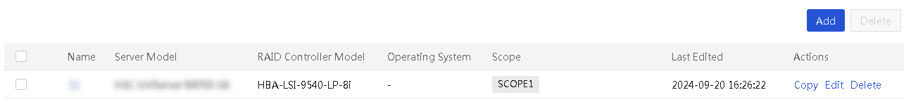
2. Click Add to enter the page as shown in Figure 132.
Figure 132 Adding a server template
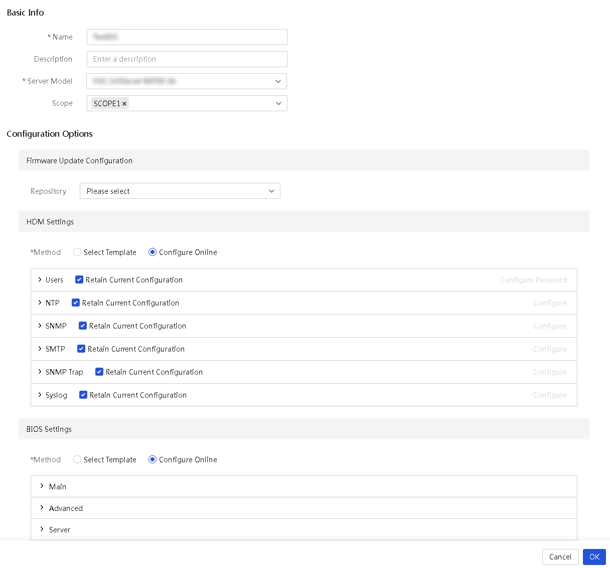
3. (Optional.) To create a server template based on an existing template, click Copy in the Actions column for the server template.
4. In the Basic Info area, enter the server template name and template description (optional), select a compatible server model from the Server Model list, and select the scope.
5. Configure Firmware Update Configuration, HDM Settings, BIOS Settings, Connection Settings, RAID Settings, and OS Settings. For more information, see the following sections.
6. To view details of a server template, click the name of the server template. If the method Use Answer File is selected for the server template in the OS settings, click Download File to download and view the answer file.
Configure HDM/BIOS templates
About this task
In a server template, you can select an exported HDM or BIOS configuration template file. Then, you can save the configuration template file in the server template and bulk apply the template to multiple servers. In this way, you can configure HDM settings and BIOS settings for multiple servers at the same time.
UniSystem allows you to export HDM settings or BIOS settings into a configuration template file. For more information, see "Configure HDM/BIOS templates."
Restrictions and guidelines
· Before applying HDM or BIOS settings to servers, make sure the HDM or BIOS of the target servers operates properly.
· Before applying an HDM template to servers, make sure the server model, HDM version, and hardware configuration of the target servers are the same as those in the HDM template.
· Before applying a BIOS template to servers, make sure the server model and BIOS version of the target servers are the same as those in the BIOS template. BIOS settings applied to a server take effect after the server is rebooted.
· After the HDM settings are successfully applied to a server, HDM of the server will automatically reboot. The HDM IP might change. If the HDM IP changes, the whole server template application process will end in advance. In this case, view the current HDM IP and add the HDM to UniSystem again.
Procedure
1. In the navigation pane, select Menu > Templates > Server Templates.
2. Click Add.
3. (Optional.) To configure the HDM or BIOS templates, click the HDM/BIOS Templates link.
4. Click Select Template in the HDM Settings or BIOS Settings area (the HDM Settings area in this example), select an exported HDM template, and click OK.

Configure HDM online
About this task
This task allows you to configure HDM online, including user, NTP, SNMP, SNMP Trap, and Syslog settings.
Procedure
1. Configure users:
|
|
IMPORTANT: Changing the default password (Password@_) of user admin might cause HDM connection errors. Please be cautious. |
a. Unselect Retain Current Configuration from the Users field.
b. Click Configure Password, and then configure the password policy.
- Enable or disable password complexity check.
- Specify password settings, such as password validity.
- Click OK.
Figure 134 Configuring the password policy
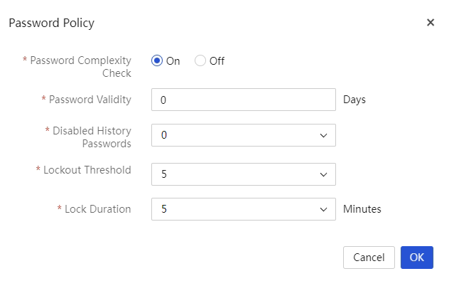
c. Click Add User, configure user settings, and then click OK.
Figure 135 Adding a user
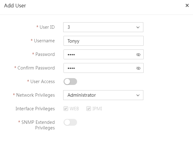
d. Click Edit for a user entry, configure user settings, and then click OK.
Figure 136 Editing a user
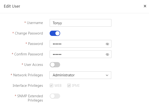
2. Configure NTP:
a. Unselect Retain Current Configuration from the NTP field.
b. Click Configure and then configure NTP:
- Enable or disable auto synchronization. This feature enables the system to synchronize time settings from the NTP server.
- Set the synchronization interval, and specify the primary, secondary, and tertiary NTP servers.
- Click OK.
Figure 137 Configuring NTP

3. Configure SNMP:
a. Unselect Retain Current Configuration from the SNMP field.
b. Click Configure and then configure SNMP:
- Select the SNMP version.
- Select whether to enable the long community string feature.
- Select Read-Only Community String or Read/Write Community String and specify the string.
- Click OK.
Figure 138 Configuring SNMP
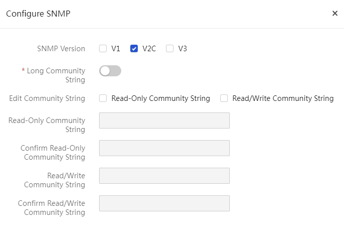
4. Configure SMTP:
a. Unselect Retain Current Configuration from the SMTP field.
b. Click Configure and then configure SNMP:
- Enable SMTP.
- Specify the SMTP server address and server port.
- Select whether to enable anonymous email. To send alert emails as anonymous emails, enable this feature. To send alert emails with sender identity information, disable this feature and enter the username and password for connecting to the SMTP server. The username is a string of 1 to 255 characters.
- Specify the sender email address. Make sure the email service uses the SMTP mail server.
- Select the severity levels. Options include Critical, Major + Critical, Minor + Major + Critical, and All.
- Select email subjects. Options include Product Name, Host Name, Asset Tag, and System Board Serial Number. This field is not available for G3 and G5 servers.
- Click OK.
Figure 139 Configuring SMTP
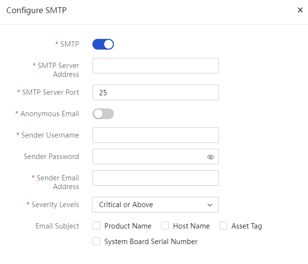
c. Click Add Email Address, and then configure recipient information:
- Select the username of the recipient. The email address of the user is automatically populated. This is available only for G3/G5 servers.
- Enter the email subject. The subject is a string of 1 to 255 characters.
- Click OK.
Figure 140 Adding an email recipient
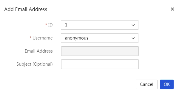
5. Configure SNMP Trap:
a. Unselect Retain Current Configuration from the SNMP Trap field.
b. Click Configure and then configure SNMP:
- Enable SNMP Trap.
- Select the SNMP Trap mode. Options include Node OID, Event OID, and Event code OID (This field is not available for G3 and G5 servers).
- Select the SNMP Trap version. If SNMPv3 is selected, you must also specify an SNMPv3 user.
- (Optional.) Enter the location of the server and contact information.
- Specify the community string and select the alarm severity levels.
- Click OK.
Figure 141 Configuring SNMP Trap
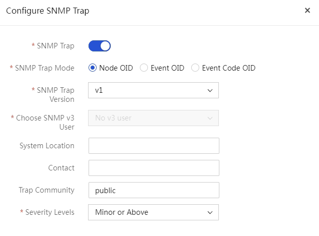
c. Click Add SNMP Trap Server, and then configure the SNMP Trap server:
- Select a server number.
- Select whether to enable the server.
- (Optional.) Specify the server address.
- Specify the port number.
- Click OK.
Figure 142 Adding an SNMP Trap server
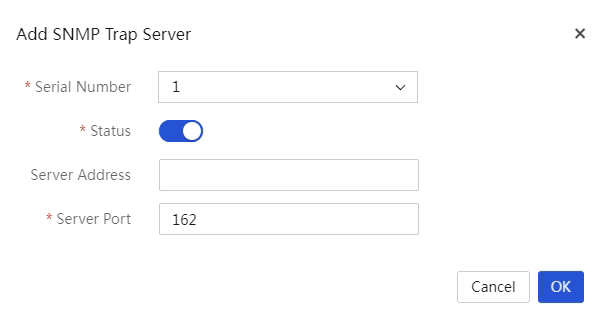
6. Configure Syslog:
|
|
NOTE: When you configure syslog settings, note that the Product serial number option is available in the Alarm log host ID field only in HDM version 2.80 and later. |
a. Unselect Retain Current Configuration from the Syslog field.
b. Click Configure and then configure SNMP.
Alarm Log Notification
- Enable log notification.
- Select an alarm log host ID, and select a transmission protocol.
- Select the log format. Options include Simplified, RFC3164, and RFC5424. This field is not available for G3 and G5 servers.
If you select the Simplified format, you must configure the custom log format. Options include Timestamp, Host Name, and Message,. The Message option is selected by default. This field is not available for G3 and G5 servers.
SDR Information Settings (G3 and G5 servers)
- Enable SDR remote information.
- Select a transmission protocol.
- Enter the server address, port number, and interval.
Host Serial Port Settings (G3 and G5 servers)
- Enable serial port information.
- Select a transmission protocol.
- Specify the server address and port number.
- Click OK.
Figure 143 Configuring Syslog
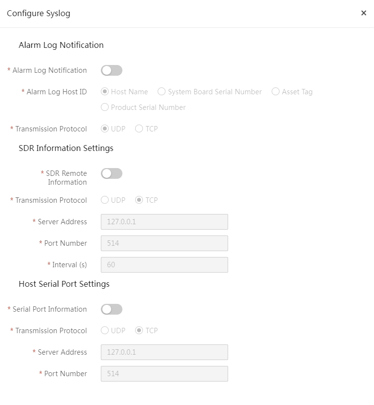
c. Click Add Alarm Log Server and then configure the alarm log server.
- Select a number.
- Select the server state.
- Enter the server name. This field is available only for G6 servers.
- Enter the server address and port number.
- Select the log type.
- Select the log severity. This field is available only for G6 servers.
- Click OK.
Figure 144 Adding an alarm log server
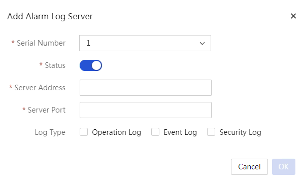
Configure the BIOS online
This task allows you to configure the BIOS online.
· Only the R4900 G3, R4330 G5, R4900 G5, R4930 G5, R4950 G5 Milan, R4950 G5 Rome, B5700 G5, R4700 G5, R6900 G5, R5300 G5, R5500 G5 Intel, R5500 G5 Milan, R5500 G5 Rome, R4700 G6, R4900 G6, and R5300 G6 servers support this feature.
· For the R4300 G6, this feature is available in BIOS 6.00.33 and later versions.
· For the R4900 G3, this feature is available in BIOS 2.58 and later versions.
· For the R4900 G5, B5700 G5, R4700 G5, R6900 G5, and R5300 G5, this feature is available in BIOS 5.45 and later versions.
· For the R4330 G5 and R4930 G5, this feature is available in BIOS 5.28 and later versions.
· For the R4950 G5 Milan, R4950 G5 Rome, R5500 G5 Intel, R5500 G5 Milan, and R5500 G5 Rome, this feature is available in BIOS 5.45 and later versions.
· For the R4700 G6, R4900 G6, and R5300 G6, this feature is available in BIOS 6.00.22 and later versions.
· For the R4950 G6, this feature is available in BIOS 6.30.26 and later versions.
· For the R5350 G6 and R5500 G6 AMD, this feature is available in BIOS 6.30.31 and later versions.
· For the R5500 G6 Intel, this feature is available in BIOS 6.00.28 and later versions.
· For the R6900 G6, this feature is available in BIOS 6.00.34 and later versions.
The BIOS options available for online configuration vary by device model. For more information, see the BIOS user guide for the device.
Figure 145 Configuring the BIOS online
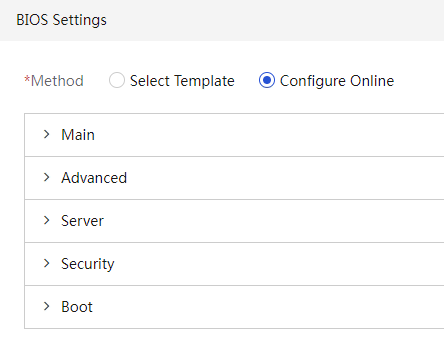
Configure connection settings
About this task
In a server template, you can define switch port-to-server port connections and assign a network to each connection. Then, you can bind the server template to the corresponding switch ports by using the auto-configuration feature to enable automated network configuration of the switch ports.
Restrictions and guidelines
The connection settings in a server template can be applied only to ports on an H3C S6850-56HF or H3C S6800-54QF switch.
A switch port will be configured as an access port after the connection settings are applied to the port.
Procedure
The configuration procedure varies by server model. This section describes these configuration procedures separately.
Add connection
1. In the navigation pane, select Menu > Templates > Server Templates.
2. Click Add to open the page for adding a server template.
3. In the Connection Settings area, click Add Connection for rack servers. In the dialog box that opens, configure the following parameters:
a. Enter a connection name in the Connection Name field.
b. Select an existing network from the Network list. For information about creating networks in UniSystem, see "Manage networks."
c. Select the NIC slot and NIC port at the server end of the connection. The HDM dedicated network port cannot be selected.
The NIC slot and NIC port settings are intended only for reference by the server administrator during network planning. The settings will not be directly applied to the actual server in the template application process.
d. Select the switch IP address and switch port at the switch end of the connection. The switch must have been added to UniSystem. For more information, see "Add a switch."
A template with a connection added can be applied only to one device.
4. Click OK to add the connection.
Figure 146 Adding a connection
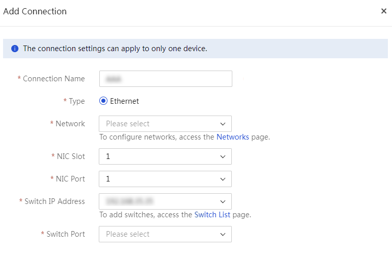
Add Mezz card
5. In the Connection Settings area, click Add Mezzanine Card for G3 blade servers. You can repeat the following steps to add multiple Mezzanine cards.
6. Select the slot number and type for a Mezzanine card.
7. Click Configure Port in the Actions column. In the dialog box that opens, configure ports as needed, as shown in Figure 147.
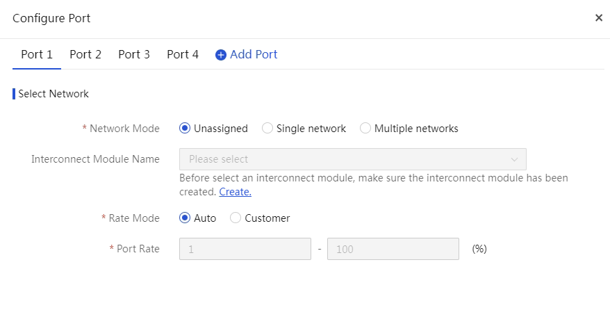
8. Select a network mode. If you select Multiple networks, you must set the server VLAN ID.
9. Select a created interconnect module template. For information about creating an interconnect module template, see "Manage interconnect module templates."
10. Select a rate mode and set a port rate.
11. Click OK.
Configure RAID configuration templates
About this task
Through preconfiguring a RAID configuration template, you can bulk configure RAID settings for servers.
Supported storage controllers
· HBA-1000-M2-1(RAID (Hide RAW) mode only)
· HBA-H460-B1
· HBA-H460-M1
· HBA-H5408-Mf-8i
· HBA-LSI-9440-8i
· RAID-L460-M4 (RAID mode only)
· HBA-LSI-9311-8i-A1-X
· RAID-LSI-9361-8i(1G)-A1-X
· RAID-LSI-9361-8i(2G)-1-X
· RAID-LSI-9460-16i(4G)
· RAID-LSI-9460-8i(4G)
· RAID-LSI-9460-8i(2G)
· HBA-LSI-9540-LP-8i
· RAID-LSI-9560-LP-8i-4GB
· RAID-LSI-9560-LP-16i-8GB
· RAID-P2404-Mf-4i-2GB
· RAID-P430-M1 (RAID (Hide RAW) mode and RAID (Expose RAW) mode)
· RAID-P430-M2 (RAID (Hide RAW) mode and RAID (Expose RAW) mode)
· RAID-P460-B2
· RAID-P460-B4
· RAID-P460-M2
· RAID-P460-M4
· RAID-P4408-Mf-8i-2GB
· RAID-P4408-Ma-8i-2GB
· RAID-P4408-Mr-8i-2GB
· RAID-P5408-Mf-8i-4GB
· RAID-P5408-Ma-8i-4GB
Restrictions and guidelines
· Make sure the storage controllers to be configured are of the same model as those specified in the RAID settings. If two storage controllers are specified in the RAID settings, make sure the corresponding slots have storage controllers of the matching models on the servers to be configured.
· Make sure the RAID member drives are present and operating properly.
Procedure
1. In the navigation pane, select Menu > Templates > Server Templates.
2. Click Add.
3. In the Basic Info area, set the parameters.
4. As shown in Figure 148, select whether to enable Retain Matching Logical Drives in the RAID Settings area. If you enable this option to retain a logical drive on a server, make sure the logical drive's member drives and RAID level match those of a logical drive configured in this area. If you do not enable this option, UniSystem will delete the existing logical drives on a server.
|
|
NOTE: · After you enable Retain Matching Logical Drives, UniSystem will retain a logical drive on a server if the logical drive's member drives and RAID level match those of a logical drive configured in this area. UniSystem will not modify the retained logical drives. For example, if the RAID name in the configuration file for a retained logical drive is different from the actual RAID name, UniSystem will not modify the RAID name of the retained logical drive. · To install an operating system to a retained logical drive, make sure the RAID name of the target drive in the OS settings area is the same as the original RAID name of the retained logical drive. · To create a hot spare drive and assign it to a reserved logical drive, the RAID name must match the original logical drive name. Otherwise, the hot spare creation fails. |
5. Click Add Storage Controller. Select a storage controller model.
Figure 148 Adding a storage controller
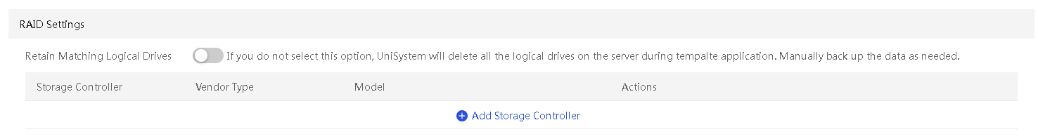
6. As shown in Figure 149, select values from the Slot Number, Vendor Type, and Model lists. The Slot Number list is available only when the selected server model supports multiple storage controllers. Click Configure to configure a logical drive.
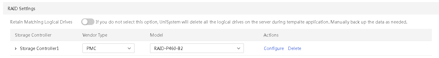
7. In the dialog box that opens as shown in Figure 150, click Add Logical Drive.
8. Enter the RAID name, and select the RAID level and physical drives.
9. Click Add Hot Spare, select the hot spare type, logical drive name, and physical drive. Only logical drives managed by a P460, LSI-9560, or LSI-9540 storage controller (excluding RAID 0 arrays) support hot spare configuration.
10. Click OK.
Figure 150 Storage controller settings
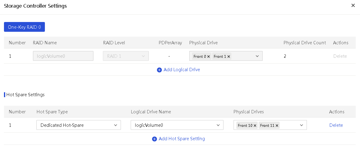
Table 12 Parameters for RAID settings
|
Parameter |
Remarks |
|
One-Key RAID 0 |
Select this option to use the remaining physical drives that have not been added to any RAID array to create RAID 0 or simple volume. Some storage controllers do not support the One-Key RAID 0 option. |
|
RAID Name |
Name of the RAID array (logical drive) to create. On the same storage controller, the RAID names must be unique. |
|
RAID Level |
Level of the logical drive to create. The available RAID levels depend on the storage controller model, as shown in Table 13. The other available storage controllers that are not listed in Table 13 support RAID 0, RAID 1, RAID 5, RAID 6, RAID 10, and RAID 50. |
|
Physical Drive |
Physical drives used to create the logical drive. |
|
PDPerArray |
Number of physical drives per sub RAID array. This parameter is required only for a RAID 50 array on an LSI controller. |
Table 13 RAID levels supported by storage controllers
|
Storage controller |
RAID levels |
|
HBA-1000-M2-1 |
RAID 0, RAID 1, and RAID 10 |
|
HBA-H460-B1 HBA-H460-M1 |
RAID 0, RAID 1, RAID 5, and RAID 10 |
|
HBA-H5408-Mf-8i |
RAID 0, RAID 1, and RAID 10 |
|
HBA-LSI-9311-8i-A1-X |
RAID 0, RAID 1, and RAID 10 |
|
RAID-P430-M1 RAID-P430-M2 |
RAID 0, RAID 1, RAID 5, RAID 6, RAID 10, RAID 50, and Simple Volume |
|
RAID-P460-B2 RAID-P460-B4 RAID-P460-M2 RAID-P460-M4 |
RAID 0, RAID 1, RAID 5, RAID 6, RAID 10, and RAID 50 |
|
HBA-LSI-9440-8i |
RAID 0, RAID 1, RAID 5, RAID 10, and RAID 50 |
|
HBA-LSI-9540-LP-8i |
RAID 0, RAID 1, and RAID 10 |
|
RAID-LSI-9560-LP-8i-4GB RAID-LSI-9560-LP-16i-8GB |
RAID 0, RAID 1, RAID 5, RAID 6, RAID 10, and RAID 50 |
|
RAID-L460-M4 |
RAID 0, RAID 1, RAID 5, RAID 6, RAID 10, and RAID 50 |
|
RAID-LSI-9361-8i(1G)-A1-X RAID-LSI-9361-8i(2G)-1-X |
RAID 0, RAID 1, RAID 5, RAID 6, RAID 10, and RAID 50 |
|
RAID-LSI-9460-8i(2G) RAID-LSI-9460-8i(4G) RAID-LSI-9460-16i(4G) |
RAID 0, RAID 1, RAID 5, RAID 6, RAID 10, and RAID 50 |
|
RAID-P2404-Mf-4i-2GB |
RAID 0, RAID 1, RAID 5, RAID 6, RAID 10, and RAID 50 |
|
RAID-P4408-Ma-8i-2GB RAID-P4408-Mf-8i-2GB RAID-P4408-Mr-8i-2GB |
RAID 0, RAID 1, RAID 5, RAID 6, RAID 10, and RAID 50 |
|
RAID-P5408-Ma-8i-4G RAID-P5408-Mf-8i-4GB-BSF-F1 |
RAID 0, RAID 1, RAID 5, RAID 6, RAID 10, and RAID 50 |
Configure OS settings
About this task
Perform this task to create the configuration templates for OS installation. When you configure the OS installation template, you must configure the OS information, which supports the exported OSs for cloning, Linux operating systems, Windows operating systems, and VMware operating systems.
To successfully apply a server template for OS installation, you must upload the OS image files on the Menu > Templates > Images page.
Supported operating systems
A server template supports installing the Red Hat Enterprise Linux, SUSE Linux Enterprise Server, CentOS, Oracle Linux, Ubuntu Server, VMware ESXi, CAS, penEuler, Kylin, Tianyi Cloud, Rocky Linux, H3Linux, and Windows Server operating systems (excluding the core versions). For more information, see Table 14.
Table 14 Supported operating systems
|
OS type |
Versions |
|
Images imported for OS cloning |
For the operating systems supported by OS cloning, see "Clone images." |
|
CentOS |
CentOS 6.10 (64 bit) |
|
CentOS 7.3 (64 bit) |
|
|
CentOS 7.4 (64 bit) |
|
|
CentOS 7.5 (64 bit) |
|
|
CentOS 7.6 (64 bit) |
|
|
CentOS 7.7 (64 bit) |
|
|
CentOS 7.8 (64 bit) |
|
|
CentOS 7.9 (64 bit) |
|
|
CentOS 8.0 (64 bit) |
|
|
CentOS 8.1 (64 bit) |
|
|
CentOS 8.2 (64 bit) |
|
|
CentOS 8.3 (64 bit) |
|
|
CentOS 8.4 (64 bit) |
|
|
Red Hat Enterprise Linux |
Red Hat Enterprise Linux 6.7 (64 bit) (includes KVM) |
|
Red Hat Enterprise Linux 6.8 (64 bit) (includes KVM) |
|
|
Red Hat Enterprise Linux 6.9 (64 bit) (includes KVM) |
|
|
Red Hat Enterprise Linux 6.10 (64 bit) (includes KVM) |
|
|
Red Hat Enterprise Linux 7.2 (64 bit) (includes KVM) |
|
|
Red Hat Enterprise Linux 7.3 (64 bit) (includes KVM) |
|
|
Red Hat Enterprise Linux 7.4 (64 bit) (includes KVM) |
|
|
Red Hat Enterprise Linux 7.5 (64 bit) (includes KVM) |
|
|
Red Hat Enterprise Linux 7.6 (64 bit) (includes KVM) |
|
|
Red Hat Enterprise Linux 7.7 (64 bit) (includes KVM) |
|
|
Red Hat Enterprise Linux 7.8 (64 bit) (includes KVM) |
|
|
Red Hat Enterprise Linux 7.9 (64 bit) (includes KVM) |
|
|
Red Hat Enterprise Linux 8.0 (64 bit) (includes KVM) |
|
|
Red Hat Enterprise Linux 8.1 (64 bit) (includes KVM) |
|
|
Red Hat Enterprise Linux 8.2 (64 bit) (includes KVM) |
|
|
Red Hat Enterprise Linux 8.3 (64 bit) (includes KVM) |
|
|
Red Hat Enterprise Linux 8.4 (64 bit) (includes KVM) |
|
|
Red Hat Enterprise Linux 8.5 (64 bit) (includes KVM) |
|
|
Red Hat Enterprise Linux 8.6 (64 bit) (includes KVM) |
|
|
Red Hat Enterprise Linux 9.0 (64 bit) (includes KVM) |
|
|
Red Hat Enterprise Linux 9.2 (64 bit) (includes KVM) |
|
|
SUSE Linux Enterprise Server |
SLES 11 SP4 (64 bit) (includes XEN & KVM) |
|
SLES 12 (64 bit) SP1 (includes XEN & KVM) |
|
|
SLES 12 (64 bit) SP2 (includes XEN & KVM) |
|
|
SLES 12 (64 bit) SP3 (includes XEN & KVM) |
|
|
SLES 12 (64 bit) SP4 (includes XEN & KVM) |
|
|
SLES 12 (64 bit) SP5 (includes XEN & KVM) |
|
|
SLES 15 (64 bit) (includes XEN & KVM) |
|
|
SLES 15 (64 bit) SP1 (includes XEN & KVM) |
|
|
Ubuntu Server |
Ubuntu Server 17.10 (64 bit) – LTS |
|
Ubuntu Server 17.10.1 (64 bit) – LTS |
|
|
Ubuntu Server 18.04 (64 bit) – LTS |
|
|
Ubuntu Server 18.04.1 (64 bit) – LTS |
|
|
Ubuntu Server 18.04.2 (64 bit) – LTS |
|
|
Ubuntu Server 18.04.3 (64 bit) – LTS |
|
|
Ubuntu Server 20.04.4 (64 bit) – LTS |
|
|
Ubuntu Server 22.04 (64 bit) – LTS |
|
|
Ubuntu Server 22.04.1 (64 bit) – LTS |
|
|
Ubuntu Server 22.04.3 (64 bit) – LTS |
|
|
Ubuntu Server 22.04.4 (64 bit) – LTS |
|
|
CAS |
CAS 5.0 E0513 |
|
CAS 5.0 E0526 |
|
|
CAS 7.0 E0782 |
|
|
Oracle Linux 8.2 |
Oracle Linux 8.2 |
|
Oracle Linux 8.6 |
|
|
Oracle Linux 9.0 |
|
|
VMware ESXi |
VMware ESXi 6.5 U1 (64 bit) |
|
VMware ESXi 6.5 U2 (64 bit) |
|
|
VMware ESXi 6.5 U3 (64 bit) |
|
|
VMware ESXi 6.7 (64 bit) |
|
|
VMware ESXi 6.7 U3 (64 bit) |
|
|
VMware ESXi 7.0 (64 bit) |
|
|
VMware ESXi 7.0 U2 (64 bit) |
|
|
VMware ESXi 7.0 U3 (64 bit) |
|
|
VMware ESXi 7.0 U2 (64 bit) |
|
|
CAS |
CAS 5.0 E0513 |
|
CAS 5.0 E0526 |
|
|
Oracle Linux |
Oracle Linux 8.2 |
|
openEuler |
openEuler 20.03 LTS SP3 for x86_64 |
|
openEuler 22.03 LTS for x86_64 |
|
|
openEuler 22.03 LTS SP1 for x86_64 |
|
|
Kylin |
Kylin advanced server operating system V10 SP2 |
|
Kylin advanced server operating system V10 SP3 |
|
|
Tianyi Cloud |
CTyunOS 2.0.1 64 bit |
|
Rocky Linux |
Rocky Linux 8.6 |
|
Rocky Linux 9.0 |
|
|
H3Linux |
H3Linux 2.0.2-SP01 |
|
NingOS |
NingOS V3 1.0.2306 |
|
NingOS V3 1.0.2311 |
|
|
NingOS V3 1.0.2403 |
|
|
Windows Server |
Microsoft Hyper-V Server 2012 R2 |
|
Microsoft Hyper-V Server 2016 |
|
|
Microsoft Hyper-V Server 2019 |
|
|
Microsoft Windows Server 2012 R2 |
|
|
Microsoft Windows Server 2016 |
|
|
Microsoft Windows Server 2019 |
|
|
Microsoft Windows Server 2012 R2 Standard |
|
|
Microsoft Windows Server 2012 R2 Datacenter |
|
|
Microsoft Windows Server 2012 R2 Essentials |
|
|
Microsoft Windows Server 2016 Essential |
|
|
Microsoft Windows Server 2016 Standard |
|
|
Microsoft Windows Server 2016 Datacenter |
|
|
Microsoft Windows Server 2019 Standard |
|
|
Microsoft Windows Server 2019 Datacenter |
|
|
Microsoft Windows Server 2022 Standard |
|
|
Microsoft Windows Server 2022 Datacenter |
Prerequisites
· Make sure the OS image file exists and contains the same OS as the server template.
· To install the Windows operating system, make sure the capacity of the target drive meets the primary partition requirements of the server template.
Procedure
1. In the OS Settings area on the page, click Configure.
2. (Optional.) As shown in Figure 151, when you select a RedHat or CentOS operating system, you can select the Use Answer File method. Click Download Template to obtain the answer file template for the system. Modify the answer file template as needed, and click the … icon next to Answer File to upload the answer file.
|
|
NOTE: If you select the Use Answer File method in the OS Settings area, click Download Template to obtain the answer file template for the system. If you completely self-define an answer file, the server template fails to be created. For the answer file format and usage, see the guidelines and the readme file in the template. |
Figure 151 Using an answer file
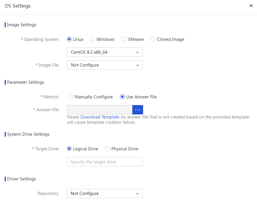
Table 15 Parameters for using an answer file
|
Parameter |
Remarks |
|
Answer File |
The operating system will be automatically installed according to the answer file. You can customize the answer file according to the downloaded template file. (This option is applicable to only the custom settings.) |
3. Configure OS-related parameters. The available parameters vary by OS type, as shown in Figure 152, Figure 153, and Figure 154. If necessary, you can select drivers to be installed from the repository. When installing an operating system on a server. iFIST will also automatically install its built-in drivers required by the operating system. For information about iFIST built-in drivers, see iFIST User Guide.
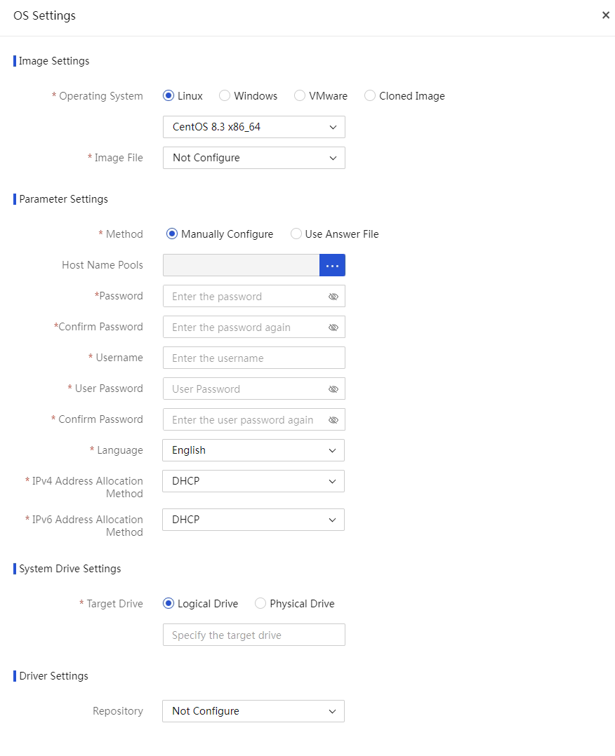
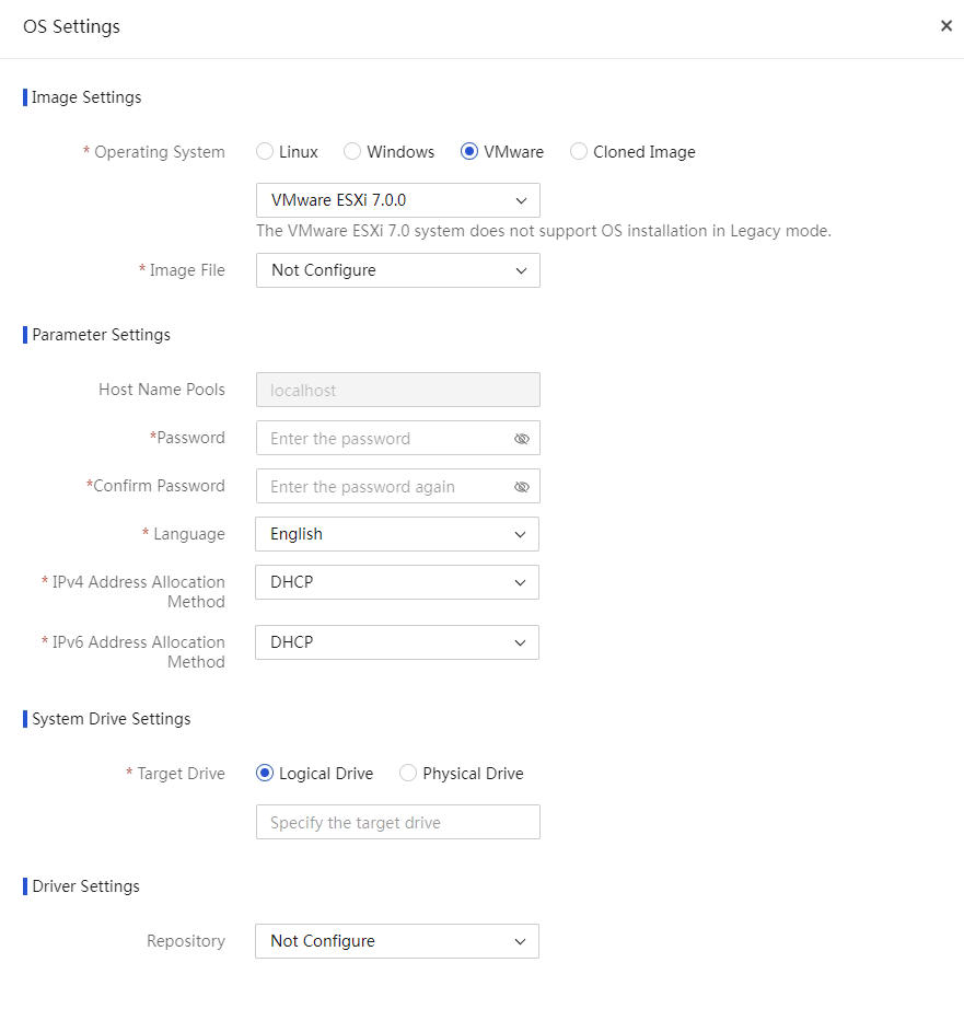
Table 16 Parameters for OS settings
|
Parameter |
Remarks |
|
Operating System |
Select the operating system type and operating system name. The OS Settings page varies by the selected operating system type. |
|
Management software packages (only for CAS 7.0 system) |
Select the installation package of the cloud computing management platform. Options include CVK, CVM-Chinese, and CVM-English. · If you are installing a service server (the physical host on which the VM resides), select Cloud Virtualization Kernel (CVK). CVK represents the virtualization kernel software that runs between the infrastructure layer and the upper-layer client operating system. · If you are installing a management server (a server that centrally manages service servers), select Cloud Virtualization Manager (CVM). CVM primarily provides software virtualization management for computing, network, and storage hardware resources in the data center, and delivers automated services to upper-layer applications. |
|
(Optional.) Host Name |
Name of the host where the operating system is to be installed. You can select a host name range in a host name pool. For more information about host name pools, see "Manage host name pools." The default host name for the Linux operating system is localhost. If you select DHCP as the IPv4 address allocation method for a VMware ESXi operating system, the Host Name field is unavailable. If you select Cloned Image for the operating system field, the default host name uses the host name in the source operating system. |
|
Password |
Password for logging in to the system. If you select a Linux operating system, the password is the root password. |
|
Username |
Username of a non-root user. NOTE: · This option is applicable only to the Linux operating system. · This option is not applicable to the VMware ESXi or CAS operating system. · When you configure a username in the Ubuntu system, do not use a reserved username of the Ubuntu system, for example, root and admin. |
|
User Password |
Password of a non-root user for logging in to the system. This option is applicable only to the Linux operating system. This option is not applicable to the VMware ESXi or CAS operating system. |
|
Language |
Language of the operating system: · Simplified Chinese. · English. NOTE: This option is not applicable to the VMware ESXi or CAS operating system. |
|
IPv4 Address Allocation Method |
Options are DHCP and Static. If you select Static, you must select an address range in an IPv4 address pool. For more information about IPv4 address pools, see "Manage IPv4 address pools." NOTE: The CAS 5.0 operating system does not support DHCP. |
|
IPv6 Address Allocation Method |
Options are DHCP and Static. If you select Static, you must select an address range in an IPv6 address pool. For more information about IPv6 address pools, see "Manage IPv6 address pools." NOTE: · The VMware ESXi operating system supports only the DHCP method. · The CAS 5.0 operating system does not support IPv6. · The Ubuntu Server operating system does not support IPv6 when IPv4 Address Allocation Method is set to Static, and it does not support IPv4 when IPv6 Address Allocation Method is set to Static. |
|
Target Drive |
Drive where the operating system is to be installed. |
|
Repository |
Select a repository. Available options are repositories in the repository library. When an inventoried repository is selected, the list will display the drivers applicable to the operating system selected on the OS Settings page. |
Figure 154 Windows OS settings
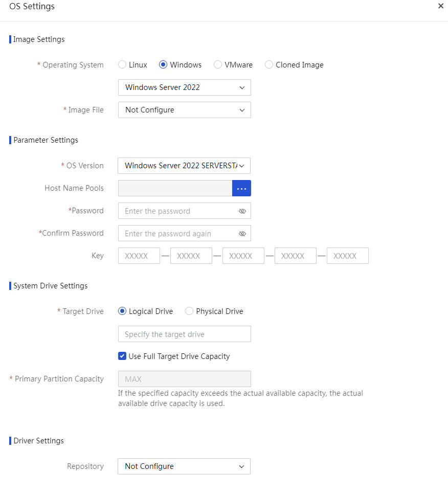
Table 17 Parameters for Windows OS settings
|
Parameter |
Remarks |
|
OS Version |
Select an OS version. (This option is applicable only to an operating system that supports multiple versions.) |
|
(Optional.) Host Name |
Name of the host where the operating system is to be installed. If this filed is left empty in the Windows operating system, the Windows operating system automatically assigns a host name. |
|
Primary Partition Capacity |
Capacity of the system partition where the operating system is to be installed, in the range of 51200 to 10485760 MB. If you select Use Full Logical Drive Capacity, the primary partition capacity is set to the maximum value available. To successfully install the operating system, make sure the capacity is no smaller than 50 GB. When the physical drive capacity is large, as a best practice, set the primary partition capacity to the maximum value. (This option is applicable only to the Windows operating systems. In the Linux operating systems, the primary partition capacity is not displayed and uses the maximum available value by default, and the minimum required drive capacity is 80 GB.) |
Configure HDM/BIOS templates
About this task
Perform this task to export the HDM/BIOS settings of a server to generate a configuration template file. Then, you can apply the configuration template file to the specified servers. This feature allows you to copy or configure HDM settings and BIOS settings for multiple servers at the same time. You can also use the configuration template file to back up the current settings of the server.
This feature depends on the HDM interface. The HDM settings imported to servers take effect after the HDMs are rebooted. The BIOS settings imported to servers take effect after the servers are rebooted.
|
|
NOTE: To use this feature, you must add HDM server nodes to UniSystem first. For more information, see "Manage servers." |
Export HDM/BIOS settings
Prerequisites
· Before exporting the settings of a server, make sure the HDM or BIOS of the server operates properly.
· The privilege to export settings depends on the network privilege of the HDM account. Make sure the user has the privilege to this operation.
· During the export process, do not switch to another page, refresh the page, or execute other configuration management operations.
· Up to 40 HDM/BIOS configuration template files can be saved. If the upper limit has been reached, manually delete the configuration template files that are not frequently used.
Procedure
1. Click HDM Settings or BIOS Settings in the Export column for the managed server, as shown in Figure 155.
To quickly filter out the target server, you can use the dynamic group and static group from the left navigation pane or enter a keyword in the search area.
Figure 155 HDM/BIOS configuration templates
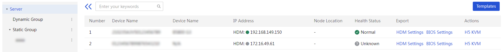
2. In the dialog box that opens, enter the template description (optional).
3. Click OK to start exporting the settings. The template file generated is automatically named [HDM/BIOS]CONFCOPY+time when the configuration was exported.json.
Manage templates
About this task
Perform this task to delete, download, and upload configuration templates.
Procedure
1. In the navigation pane, select Menu > Templates > HDM/BIOS Templates.
2. Click Templates to enter the template management page, as shown in Figure 156.
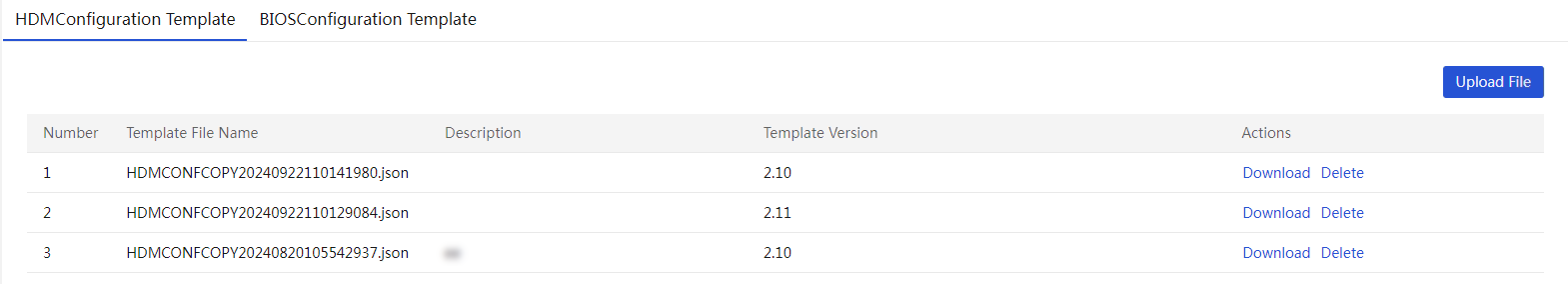
3. Click the HDM Templates or BIOS Templates tab.
4. Click Upload File.
5. In the dialog box that opens, click the … icon for the Upload File field, and select the configuration file to upload.
6. (Optional.) Enter the template description.
7. Click OK.
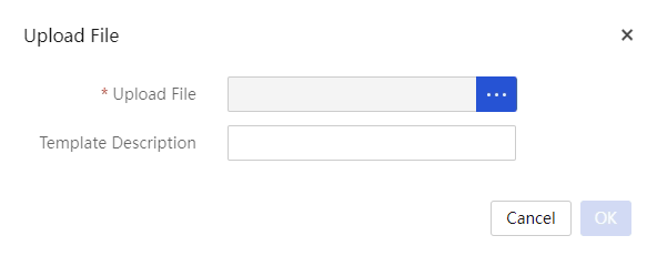
8. (Optional.) To download a configuration template file, click Download for the template to download, select the path to save the configuration template file, and click OK.
9. (Optional.) To delete a configuration template file, click Delete for the template to delete. In the dialog box that opens, click OK.
Configure repositories
About this task
A repository is a compressed file containing various drivers for various optional cards and the system board and containing firmware for various HDM, BIOS, CPLD, drives, and optional cards. The firmware and drivers are collectively referred to as components.
From this menu, you can add, edit, delete, inventory, and customize repositories. You can use Add a repository to manually upload a repository or use Enable LastestREPO update to automatically upload a repository.
By using this feature together with the component update feature, you can bulk update the firmware and drivers for servers.
|
|
IMPORTANT: To update drivers in the component update process, make sure the managed servers have FIST SMS installed. |
Network diagram
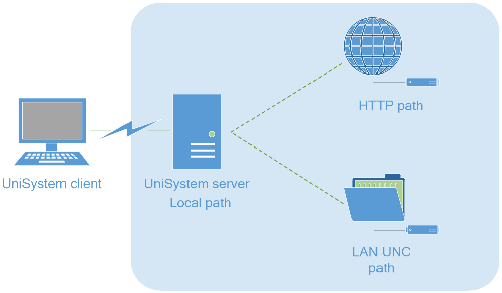
Add a repository
As of version 2.00.22, UniSystem will automatically inventory a repository after the repository is added.
Prerequisites
Prepare the repositories, and prepare the path types and paths for obtaining the repositories. The repository paths include three types, as shown in Table 18.
Table 18 Repository path types
|
Type |
Remarks |
|
UNC path |
Network path, through which you can obtain repository resources in a LAN through sharing resources. |
|
HTTP path |
HTTP server path, through which you can obtain repository resources on the specified HTTP server. |
|
Local path |
Local path, through which you can obtain repository resources on the UniSystem client. |
Procedure
1. In the navigation pane, select Menu > Templates > Repositories to enter the page as shown in Figure 159.
Figure 159 Repository management page
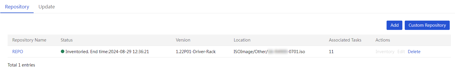
2. Click Add. In the dialog box that opens, configure parameters as needed.
¡ If you select UNC Path as shown in Figure 160, you must enter the repository path, username, and password, and then click OK.
Figure 160 Adding a repository on an UNC path
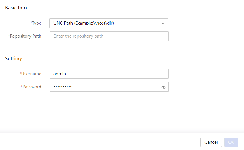
¡ If you select HTTP Path as shown in Figure 161, perform the following steps:
- Enter the repository path.
- To use the proxy to connect to an HTTP server, select Menu > System > System > Proxy Settings. For more information, see "Configuring proxy settings."
- Click OK.
Figure 161 HTTP path repository

¡ If you select Local Path as shown in Figure 162, perform the following steps:
- Click Upload.
- In the dialog box that opens, select the repository file, and then click Upload.
Figure 162 Adding a repository on a local path
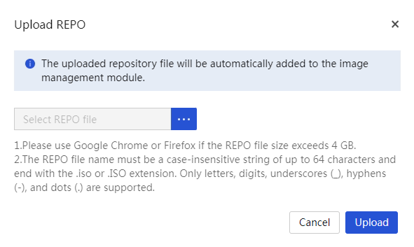
After you add a local repository to UniSystem, the repository list displays the newly added repository, and the repository will be automatically added to image list on the Menu > Templates > Images page.
Inventory a repository
About this task
Perform this task to list all components in a repository. After a repository is inventoried, its component list can display the corresponding components. In this case, the repository can be used properly.
Procedure
1. As shown in Figure 163, click Inventory in the Actions column for the repository that you want to inventory. Then, UniSystem will automatically inventory the selected repository.
Figure 163 Inventorying a repository

2. As shown in Figure 163, after inventorying is completed, the Status column for the repository displays Inventoried and the time when inventorying was completed.
3. Click the link in the Repository Name column for the target repository. The repository details page opens to display the repository information, as shown in Figure 164.
Figure 164 Repository Details
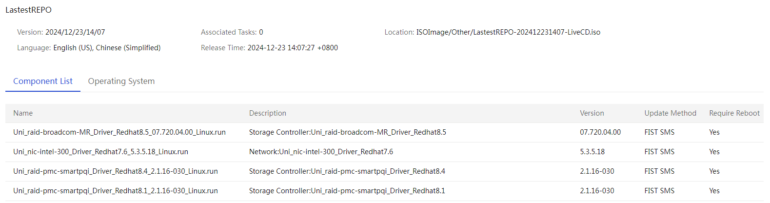
(Optional) Create a custom repository or ISO file
About this task
Perform this task to select update packages for the specified components from the added and inventoried repositories and use them to create a custom repository or ISO file.
· After creating the custom repository, you can use it to upgrade components.
· After you create a custom ISO file, an ISO image file will be generated.
As of version 2.00.22, UniSystem will automatically inventory a custom repository after the custom repository is added.
Procedure
1. In the navigation pane, select Menu > Templates > Repositories to enter the repository management page.
2. Click Custom Repository. In the dialog box that opens, perform the following steps:
a. In the Basic Info area, enter the repository name and version, and then select Create ISO or Custom Repository for Build Type.
b. In the Source Repositories area, select the target repositories.
c. In the Filters area, select the target items, and then click Apply Filters to display the matching items.
d. In the component list, select the target components.
Figure 165 Creating a custom repository
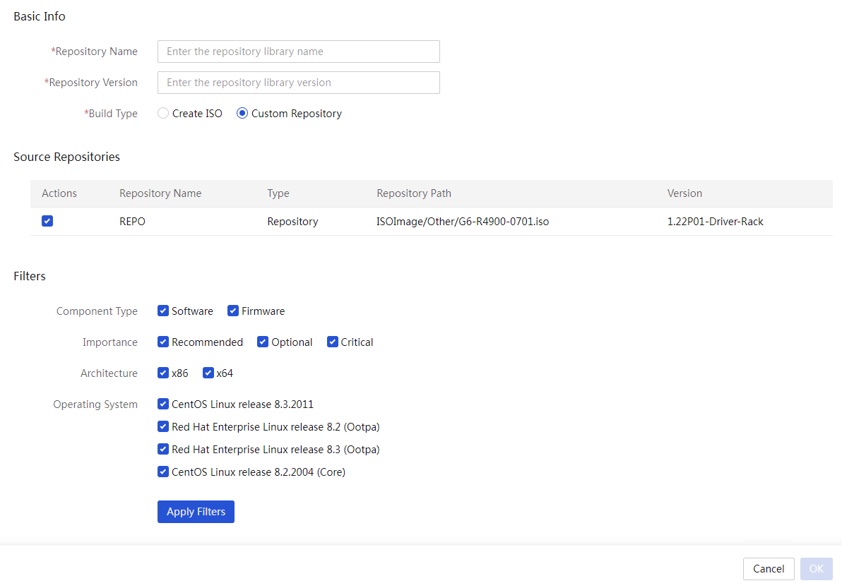
3. Click OK.
Edit a repository
About this task
Perform this task to edit a repository that has been added by a user but has not been inventoried. A custom repository, a local repository, or an inventoried repository cannot be edited. Depending on how a repository is added, you can perform either of the following tasks:
· For a repository added through an UNC path, when the username and password of the shared server change, you must synchronously edit the information on UniSystem.
· For a repository added through an HTTP server path, when the proxy option of the HTTP server changes between No Proxy and Manually Configure, you must synchronously edit the information on UniSystem.
Procedure
1. In the navigation pane, select Menu > Templates > Repositories.
2. Click Edit in the Actions column for the repository to edit.
3. In the dialog box that opens, perform the following tasks:
¡ For a repository added through an UNC path, you can edit only the username and password of the shared server.
¡ For a repository added through an HTTP server path, you can switch the proxy option between No Proxy and Manually Configure and configure related parameters.
4. Click OK.
Enable LastestREPO update
About this task
With this feature enabled, UniSystem will regularly retrieve information about the latest version of LiveCD and all component packages from the REPO online platform, based on the update interval and time set by the user. The system then filters out the suitable components for the managed servers and generates a new LiveCD REPO package to replace the older version in the image pool. It also supports automatic synchronization to replace the REPO.
· The LastestREPO feature, combined with the scheduled update feature in the "Manage server templates", allows for automatic updating of server components to the latest version.
· The LastestREPO feature, combined with the "Update components" feature, enables timely updates of server components to the latest version.
|
|
NOTE: · Before enabling LastestREPO update, make sure the UniSystem server address and the domain address of the REPO online platform are able to communicate properly. · The LastestREPO update feature does not affect the REPO packages manually uploaded by users. |
Restrictions and guidelines
After enabling update prompt, when UniSystem starts downloading and updating the latest version of the REPO package, the web page displays a prompt for the user to check the download progress or update status. The prompt will only disappear when the user manually clicks the prompt or disables the update prompt feature.
Procedure
1. In the navigation pane, select Menu > Templates > Repositories.
2. Click the Update tab.
Figure 166 Updating LastestREPO
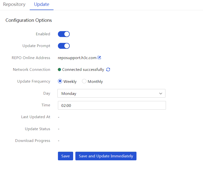
3. Enable this feature.
4. Enable update prompt.
5. Click the ![]() icon and enter
the domain name address of the REPO official website.
icon and enter
the domain name address of the REPO official website.
6. Click the ![]() icon to refresh the
network connection status.
icon to refresh the
network connection status.
7. If the network connection fails, troubleshoot issues based on recommended actions.
8. Specify the update frequency.
9. Click Save. The system will save and deploy the update configuration.
10. (Optional.) Click Save and Update Immediately. The system executes the update immediately.
Manage switch templates
Access the switch template list page
1. In the navigation pane, select Menu > Templates > Switch Templates.
2. View information about the switch templates on the switch template list.
Figure 167 Switch template list page
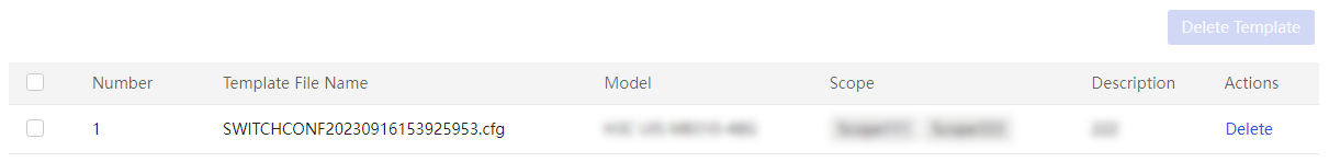
Delete switch templates
1. In the navigation pane, select Menu > Templates > Switch Templates.
2. Select the switch templates you want to delete, and then click Delete Template in the upper right corner. Alternatively, click Delete in the Actions column for the switch template you want to delete.
3. Click OK in the confirmation dialog box that opens.
Manage address pools
From this menu, you can create, edit, delete, and view IPv4 address pools, IPv6 address pools, and host name pools. After creating address pools, you can select a host name pool, IPv4 address pool, or IPv6 address pool rather than manually configure it in the OS Settings area when adding a server template. This feature significantly improves the configuration efficiency.
Manage IPv4 address pools
View IPv4 address pools
Procedure
1. In the navigation pane, select Menu > Templates > Address Pools.
2. Click the IPv4 Address Pools tab. View the IPv4 address pool list.
Figure 168 IPv4 address pools
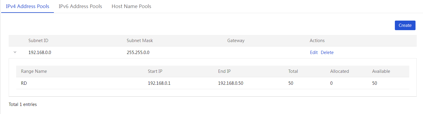
Create an IPv4 address pool
1. In the navigation pane, select Menu > Templates > Address Pools.
2. Click the IPv4 Address Pools tab. Click Add to open the Create IPv4 Address Pool page.
Figure 169 Creating an IPv4 address pool

3. Enter the IPv4 subnet ID, subnet mask, and gateway (optional).
4. In the Address Ranges area, click Add. Enter the address range name, start IP, and end IP.
5. To add more address ranges, repeat the step above.
6. Click OK.
Edit an IPv4 address pool
Restrictions and guidelines
For an IPv4 address pool with address ranges, you cannot edit its subnet ID or subnet mask.
Procedure
1. In the navigation pane, select Menu > Templates > Address Pools.
2. Click the IPv4 Address Pools tab.
3. Click Edit in the Actions column for the address pool to be edited. Edit the address pool as needed.
4. Click OK.
Delete an IPv4 address range
1. In the navigation pane, select Menu > Templates > Address Pools.
2. Click the IPv4 Address Pools tab.
3. Click Edit in the Actions column for the address pool to be edited.
4. In the Address Ranges area, click Delete in the Actions column for the address range to be deleted.
Delete an IPv4 address pool
Restrictions and guidelines
Deleting an IPv4 address pool deletes all address ranges in the IPv4 address pool.
Procedure
1. In the navigation pane, select Menu > Templates > Address Pools.
2. Click the IPv4 Address Pools tab.
3. Click Delete in the Actions column for the IPv4 address pool to be deleted. In the dialog box that opens, click OK.
Manage IPv6 address pools
View IPv6 address pools
1. In the navigation pane, select Menu > Templates > Address Pools.
2. Click the IPv6 Address Pools tab. View the IPv6 address pool list.
Figure 170 IPv6 address pools
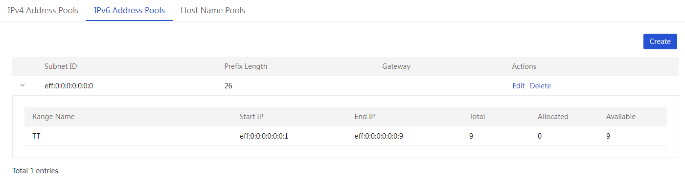
Create an IPv6 address pool
1. In the navigation pane, select Menu > Templates > Address Pools.
2. Click the IPv6 Address Pools tab. Click Add to open the Create IPv6 Address Pool page.
Figure 171 Creating an IPv6 address pool
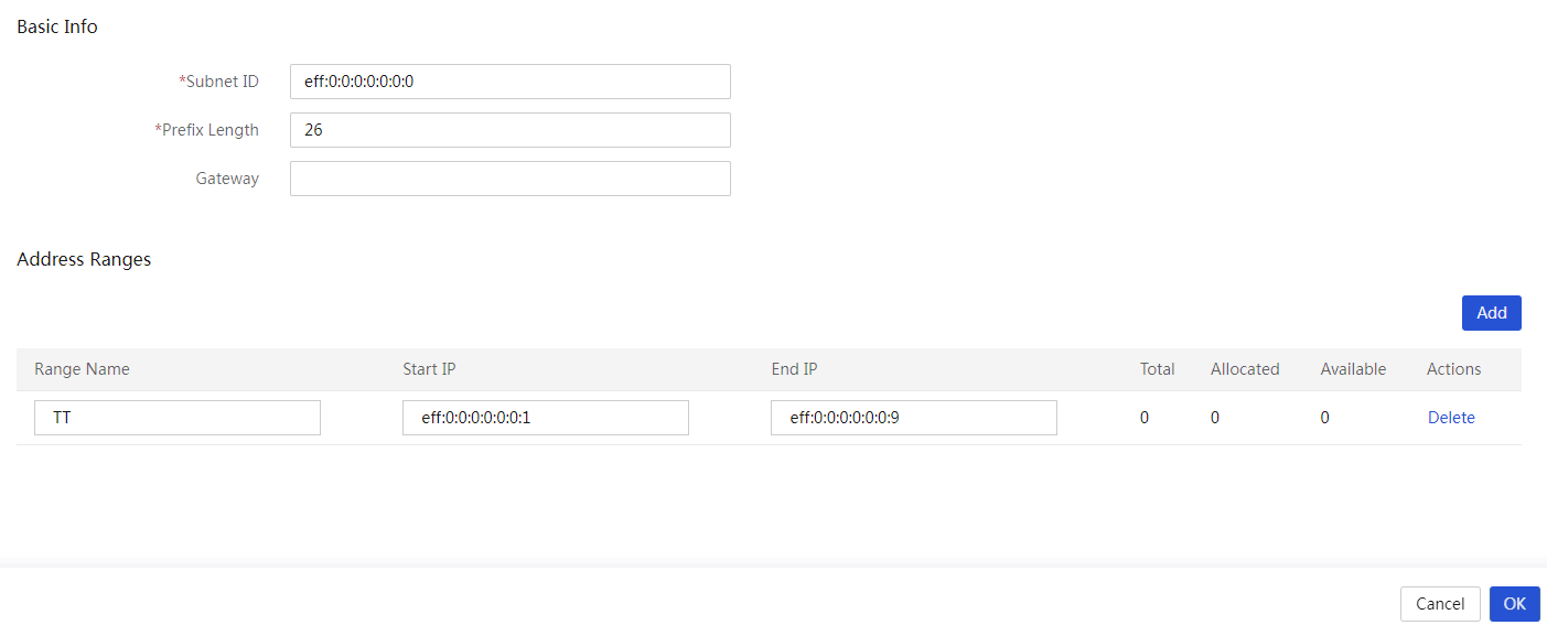
3. Enter the IPv6 subnet ID, prefix length, and gateway (optional).
4. In the Address Ranges area, click Add. Enter the address range name, start IP, and end IP.
5. To add more address ranges, repeat the step above.
6. Click OK.
Edit an IPv6 address pool
Restrictions and guidelines
For an IPv6 address pool with address ranges, you cannot edit its subnet ID or prefix length.
Procedure
1. In the navigation pane, select Menu > Templates > Address Pools.
2. Click the IPv6 Address Pools tab.
3. Click Edit in the Actions column for the address pool to be edited. Edit the address pool as needed.
4. Click OK.
Delete an IPv6 address range
1. In the navigation pane, select Menu > Templates > Address Pools.
2. Click the IPv6 Address Pools tab.
3. Click Edit in the Actions column for the address pool to be edited.
4. In the Address Ranges area, click Delete in the Actions column for the address range to be deleted.
Delete an IPv6 address pool
Restrictions and guidelines
Deleting an IPv6 address pool deletes all address ranges in the IPv6 address pool.
Procedure
1. In the navigation pane, select Menu > Templates > Address Pools.
2. Click the IPv6 Address Pools tab.
3. Click Delete in the Actions column for the IPv6 address pool to be deleted. In the dialog box that opens, click OK.
Manage host name pools
When adding a server template, you can directly select a host name pool rather than manually configure one in the OS Settings area. After the server template is applied to multiple servers to install OSs on these servers, the host names are generated for these servers in the format of prefix+index+suffix without manual configuration. This feature helps you easily identify the servers and improves the configuration efficiency.
View host name pools
Procedure
1. In the navigation pane, select Menu > Templates > Address Pools.
2. Click the Host Name Pools tab. View the host name pool list.
Figure 172 Host name pools

Create a host name pool
1. In the navigation pane, select Menu > Templates > Address Pools.
2. Click the Host Name Pools tab. Click Add to enter the Create Host Name Pool page.
Figure 173 Creating a host name pool
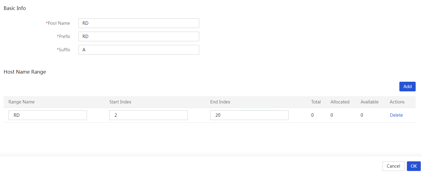
3. Enter the host name pool name, prefix, and suffix.
4. In the Host Name Ranges area, click Add. Enter the host name range name, start index, and end index.
5. To add more host name ranges, repeat the step above.
6. Click OK.
Edit a host name pool
1. In the navigation pane, select Menu > Templates > Address Pools.
2. Click the Host Name Pools tab.
3. Click Edit in the Actions column for the host name pool to be edited. Edit the host name pool as needed.
4. Click OK.
Delete a host name range
1. In the navigation pane, select Menu > Templates > Address Pools.
2. Click the Host Name Pools tab.
3. Click Edit in the Actions column for the host name pool to be edited.
4. In the Host Name Ranges area, click Delete in the Actions column for the host name range to be deleted.
Delete a host name pool
Restrictions and guidelines
Deleting a host name pool deletes all host name ranges in the host name pool.
Procedure
1. In the navigation pane, select Menu > Templates > Address Pools.
2. Click the Host Name Pools tab.
3. Click Delete in the Actions column for the host name pool to be deleted. In the dialog box that opens, click OK.
Manage network templates
From this menu, you can create, edit, delete, and view network templates or interconnect module templates in UniSystem. Then, you can use the networks and interconnect module templates when configuring connections in a server template. For more information about, see connecting settings in "Manage server templates."
Manage networks
From this menu, you can create, edit, delete, and view networks in UniSystem.
View a network
1. In the navigation pane, select Menu > Templates > Network Templates. Click the Networks tab.
2. View information about the networks on the network list. The network name format varies depending on whether a single VLAN ID or a VLAN ID range was specified during the network creation:
¡ If a VLAN ID range was specified, the network name takes the format of Network Name_VLAN ID. For example, wl1_10.
¡ If a single VLAN ID was specified, the network name takes the format of Network Name. For example, Test.
Figure 174 Networks
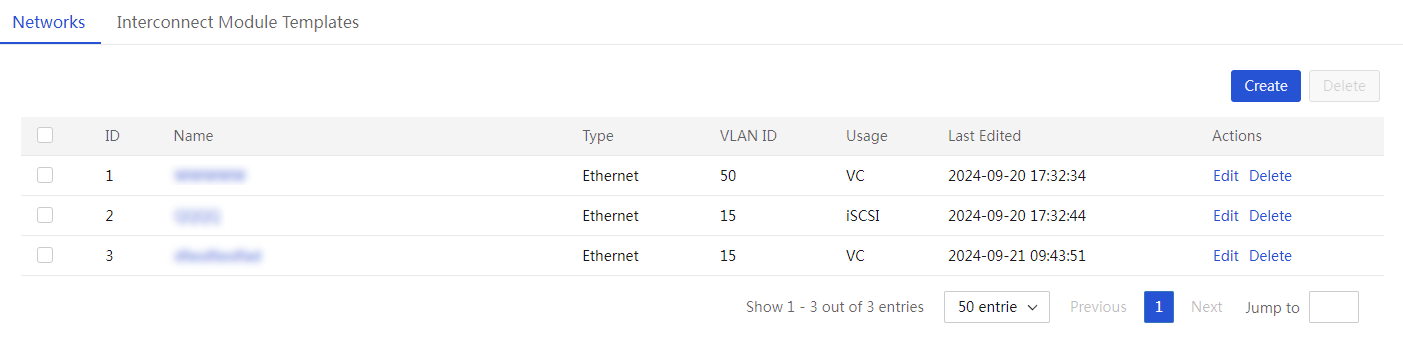
Create networks
1. In the navigation pane, select Menu > Templates > Network Templates. Click the Networks tab.
2. Click Create. The Create Network dialog box opens.
To create interconnect module templates later, you must select VC from the Usage list.
Figure 175 Creating networks
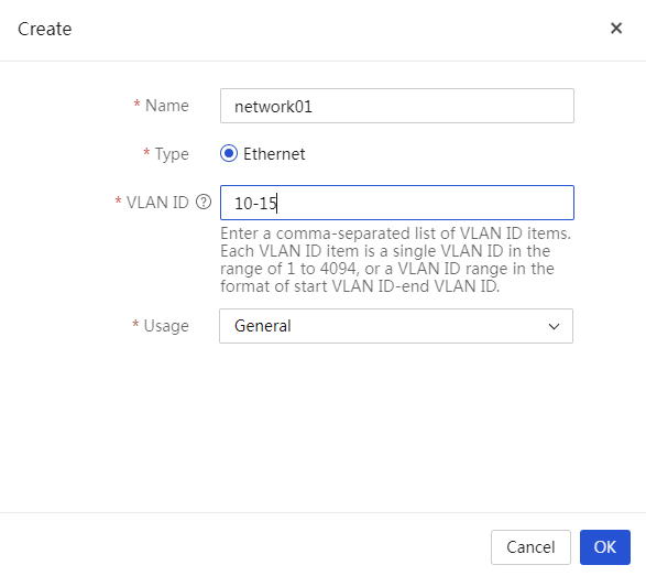
3. Configure the network parameters as follows:
¡ To create a single network, specify the network name and a VLAN ID for the network, configure other parameters as needed, and then click OK.
UniSystem will create only one network with the specified network name.
¡ To create multiple networks with the same network name and different VLAN IDs, specify the network name and the VLAN ID list, configure other parameters as needed, and then click OK.
UniSystem will create a network for each VLAN with a name in the format of Network Name_VLAN ID, for example, Blue_100.
4. Verify that the newly created networks are displayed on the Networks page.
Figure 176 Viewing the created networks
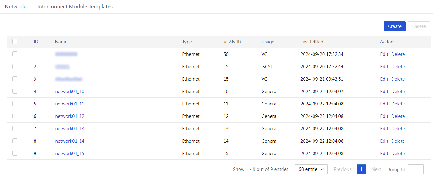
Edit a network
1. In the navigation pane, select Menu > Templates > Network Templates. Click the Networks tab.
2. Click Edit in the Actions column for the network to be edited.
3. Edit the network settings as needed.
4. Click OK.
Delete networks
1. In the navigation pane, select Menu > Templates > Network Templates. Click the Networks tab.
2. Perform either of the following steps:
¡ To bulk delete networks, select the networks and click Delete.
¡ To delete a single network, click Delete in the Actions column for the network.
3. In the dialog box that opens, click OK to confirm the operation.
Manage interconnect module templates
From this menu, you can create, edit, or delete the interconnect module templates.
View an interconnect module template
1. In the navigation pane, select Menu > Templates > Network Templates. Click the Interconnect Module Templates tab.
2. On this tab, view the interconnect module template information.
Figure 177 Interconnect module template information page
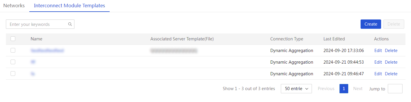
Create an interconnect module template
1. In the navigation pane, select Menu > Templates > Network Templates.
2. Click the Interconnect Module Templates tab.
3. Click Create.
4. In the dialog box that opens, configure the interconnect module template.
The Network list displays only networks with the usage as VC.
Figure 178 Creating an interconnect module template
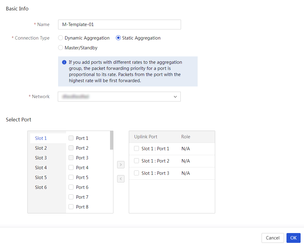
5. Click OK.
Figure 179 Interconnect module template list
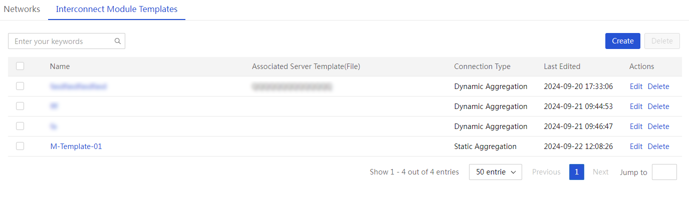
Edit an interconnect module template
1. In the navigation pane, select Menu > Templates > Network Templates.
2. Click the Interconnect Module Templates tab.
3. Click Edit in the Actions column for the interconnect module to be edited.
4. Click OK.
Delete an interconnect module template
1. In the navigation pane, select Menu > Templates > Network Templates.
2. Click the Interconnect Module Templates tab.
3. Perform either of the following steps:
¡ To bulk delete interconnect modules, select the interconnect modules and click Delete.
¡ To delete a single interconnect module, click Delete in the Actions column for the interconnect module.
4. In the dialog box that opens, click OK to confirm the operation.
Manage images
Restrictions and guidelines
· When the free space is about 10G, you cannot upload images. In this case, as a best practice, delete the images that are not needed.
· When UniSystem runs in Windows, for an uploaded image file to be used properly, you must run UniSystem as an administrator.
· The name of an image file to upload can contain up to 64 characters, including the file extension.
· For the upload to succeed, make sure the name of the image to upload is different from the name of any image on the image list.
· For the upload to succeed, do no refresh the page during the upload process.
· To avoid exceptions during operating system installation, make sure the image file to upload is downloaded from its official website and has not been edited.
Procedure
1. In the navigation pane, select Menu > Templates > Images to enter the page as shown in Figure 180.
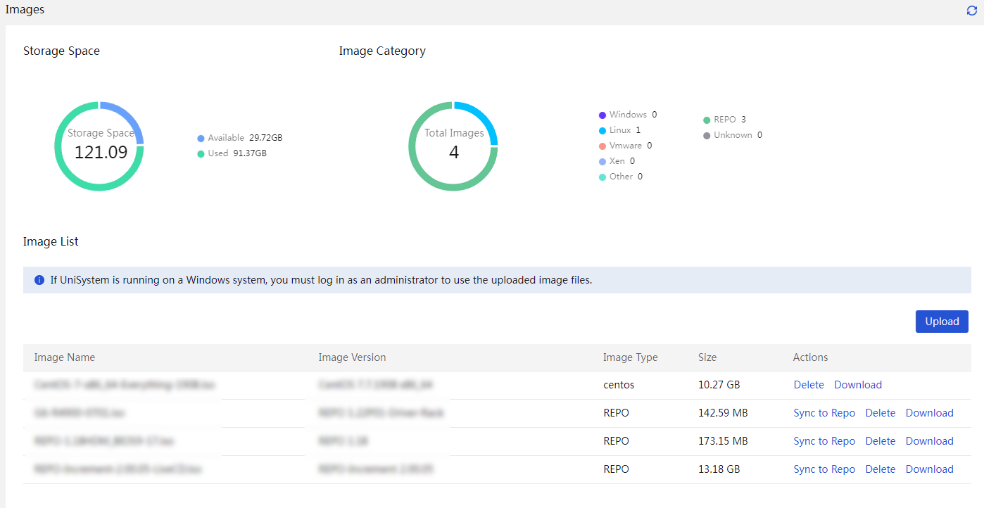
2. Click Upload in the upper right corner of the image list. The Upload Image dialog box opens, as shown in Figure 181.
Figure 181 Uploading an OS image
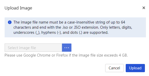
3. Click the Browse button. In the dialog box that opens, select the image file to upload.
4. Click Upload to upload the OS image file to the UniSystem server.
After the upload is completed, the OS image file is displayed on the image management page.
5. (Optional.) If the uploaded image file is a repository file, you can synchronize the file to the Menu > Templates > Repositories page by clicking Sync to Repo in the Actions column for the file.
Clone images
About this task
|
|
IMPORTANT: · This feature is available only when UniSystem runs in the AE module or the VM. · To use this feature, you must add HDM server nodes to UniSystem first. For more information, see "Manage servers." · To use this feature, you must install iFIST on the managed servers, and make sure iFIST has a system IP address that can communicate with UniSystem. · This feature is supported in version 2.00.13 and later. · This feature supports VMware operating systems in version 2.00.15 and later. |
This feature allows you to perform the following tasks:
· Export images for OS cloning: Perform this task to export the OS file on the specified logical drive of a server and save the file as an image file. This function supports exporting the following OSs:
¡ OSs manually installed through images mounted to KVM or USB flash drive.
¡ OSs installed through iFIST.
¡ OSs installed through server templates.
¡ OSs installed through PXE.
· Manage images: Manage image files. Perform this task to display image-related information, delete image files, and delete the tags for applying images to blade servers.
The exported image files for OS cloning can be added to the OS settings in a server template and applied. For more information, see "Manage server templates" and "Apply server templates."
Table 19 describes the support of OS cloning for operating systems.
Table 19 Support of OS cloning for operating systems
|
Operating systems |
Servers |
|
· Red Hat Enterprise Linux 7.2(64 bit) · Red Hat Enterprise Linux 7.3(64 bit) · Red Hat Enterprise Linux 7.4(64 bit) · Red Hat Enterprise Linux 7.5(64 bit) · Red Hat Enterprise Linux 7.6(64 bit) · Red Hat Enterprise Linux 7.7(64 bit) · Red Hat Enterprise Linux 7.8(64 bit) · Red Hat Enterprise Linux 7.9(64 bit) · Red Hat Enterprise Linux 8.0(64 bit) · Red Hat Enterprise Linux 8.1(64 bit) · Red Hat Enterprise Linux 8.2(64 bit) · Red Hat Enterprise Linux 8.3(64 bit) · Red Hat Enterprise Linux 8.4(64 bit) · Red Hat Enterprise Linux 9.0(64 bit) · CentOS 7.4 (64 bit) · CentOS 7.5 (64 bit) · CentOS 7.6 (64 bit) · VMware ESXi 6.5 U1 (64 bit) · VMware ESXi 6.5 U2 (64 bit) · VMware ESXi 6.5 U3 (64 bit) · VMware ESXi 6.7 (64 bit) · VMware ESXi 7.0 (64 bit) · VMware ESXi 7.0 U3 (64 bit) · VMware ESXi 8.0 (64 bit) |
· H3C UniServer B5700 G3 · H3C UniServer B5800 G3 · H3C UniServer B7800 G3 · H3C UniServer E3200 G3 · H3C UniServer R2700 G3 · H3C UniServer R2900 G3 · H3C UniServer R4700 G3 · H3C UniServer R4900 G3 · H3C UniServer R4950 G3 · H3C UniServer R5300 G3 · H3C UniServer R6700 G3 · H3C UniServer R6900 G3 · H3C UniServer R8900 G3 · H3C UniServer R4500 G3 · H3C UniServer R4900 G5 · H3C UniServer R4700 G5 · H3C UniServer R6900 G5 · H3C UniServer R4300 G5 · H3C UniServer R4950 G5 · H3C UniServer R4930 G5 · H3C UniServer R4330 G5 · H3C UniServer R5500 G5 · H3C UniServer B5700 G5 · H3C UniServer R5300 G5 |
Restrictions and guidelines
· This function cannot export partition-encrypted OSs
· UniSystem supports only LSI storage controllers operating in RAID mode (some LSI storage controllers do not require operating mode configuration).
· Before exporting images for OS cloning, make sure the HDM of the server operates properly and is turned on.
· Before exporting the OS image from a logical or physical drive on a server, make sure the drive is in valid state and has only one operating system installed.
· When the free space is 10G or lower, you cannot export images for cloning. In this case, as a best practice, delete the images that are not needed. For more information about the free space, access the Menu > Templates > Images page. During the clone&export process, do not power off or reboot the server. The clone&export process takes several minutes. Please wait patiently.
· When exporting images for OS cloning, follow these restrictions and guidelines according to the OS type:
¡ Linux
- When the server operates in UEFI mode, you can export only the operating systems installed in UEFI mode. When the server operates in legacy mode, you can export only the operating systems installed in legacy mode.
- The data in the system partitions (including /, /usr, /usr/local, /var, and /home) can be exported. If files in the /run, /proc, /media, and /sys directories are not exported, data in the other partitions (including swap and data partitions) cannot be exported.
- After you apply a cloned OS image file to a server, the partition information on the server is the same as the OS before export. Supported file systems include ext2, ext3, ext4, VFAT, XFS, and LVM. The btrfs file system is not supported. LVM thin provisioning supports only the liner mode.
¡ VMware ESXi
- Before exporting images for OS cloning, make sure the OS had been normally shut down once rather than shut down by forcibly powering off, so that the OS can save the configuration file related to the system status. Otherwise, the network settings in the image when you clone and export the image do not take effect.
- Data files of the VMware ESXi operating system cannot be exported. As a best practice, separate the system partitions from the data partitions.
- After applying a cloned image file, to create data partitions in the system logical drive, you must create them manually. A cloned OS image does not support retaining data partitions in the VMware ESXi operating system.
Procedure
1. In the navigation pane, select Menu > Templates > Images > Clone Images.
To quickly filter out the target image, you can use the static group and dynamic group from the left navigation pane or enter a keyword in the search area.
Figure 182 Clone Images
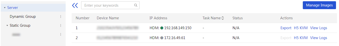
2. Click Export in the Actions column for a device, as shown in Figure 183. In the dialog box that opens, specify a name for the clone&export task, specify a name for the OS image file to be exported, select a storage controller and target drive, and click OK to issue the cloning instruction.
Figure 183 Exporting images for OS cloning
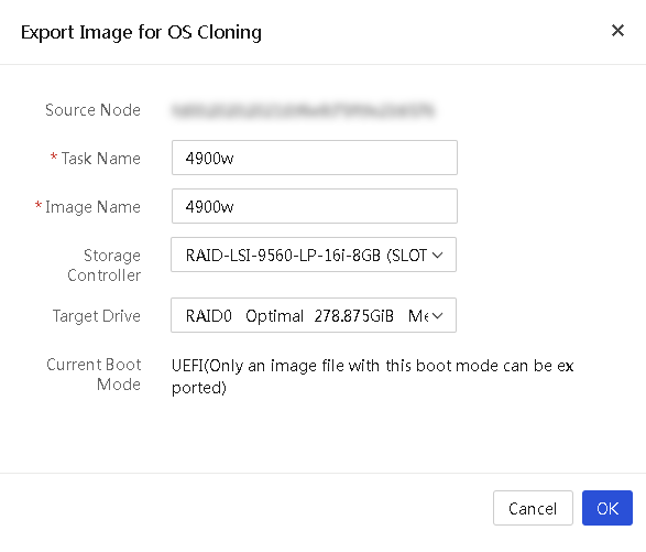
3. To see the cloning progress, see the Status column.
4. Click Manage Images to enter the image management page as shown in Figure 184. On this page, you can view the type and size of each exported image file.
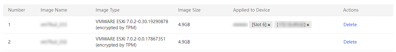
5. (Optional.) To delete an image, click Delete for the image to delete. In the dialog box that opens, click OK.
6. To view detailed logs, click View Logs for the device.
Configure diskless boot
Introduction
|
|
IMPORTANT: · This feature is available only when UniSystem runs in the AE module. · This feature is supported in version 2.00.13 and later. |
This feature complies with the iSCSI protocol and provides a remote storage volume for blade servers. You can manually install operating systems in the storage volume to implement diskless boot. For how to connect to a remote storage volume and install operating systems in the volume, see “Appendix.”
When using diskless boot, as a best practice, use the local drives only as data drives, and make sure the local drives have no OS installed and have no system boot programs. Otherwise, the diskless boot process might be affected after an OS is installed.
Storage volumes for diskless boot can be connected only when BIOS operates in UEFI mode.
Common file systems (for example, ext4 and xfs) cannot be mounted to multiple nodes at the same time. Therefore, except when you use a special cluster file system, do not try to use two NICs to connect to the same iSCSI volume. Otherwise, the file system might be damaged and the OS might fail to start.
Supported operating systems
|
|
IMPORTANT: This feature supports VMware operating systems in version 2.00.15 and later. |
The following operating systems support diskless boot:
· Red Hat Enterprise Linux 7.5 (64 bit)
· Red Hat Enterprise Linux 8.2 (64 bit)
· CentOS 7.5 (64 bit)
· CentOS 8.2 (64 bit)
· VMware ESXi 6.5 U2 (64 bit)
· VMware ESXi 6.7 (64 bit)
· VMware ESXi 7.0 U2 (64 bit)
Create a volume
About this task
Perform this task to create an empty iSCSI volume for the iSCSI client to connect. You can manually install operating systems in the storage volume to implement diskless boot.
Procedure
1. In the navigation pane, select Menu > Templates > Diskless Boot to enter the page as shown in Figure 185. On this page, you can view existing iSCSI volumes.
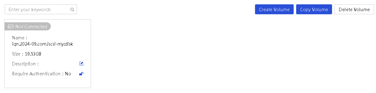
2. Click Create Volume. In the dialog box that opens, enter the name, capacity, and description for the volume.
|
|
NOTE: The iSCSI volume name must comply with the iSCSI Qualified Name (IQN) format as follows: iqn.yyyy-mm.<reversed domain name>[:identifier], for example, iqn.2014-10.dev.iscsi-target:disk. |
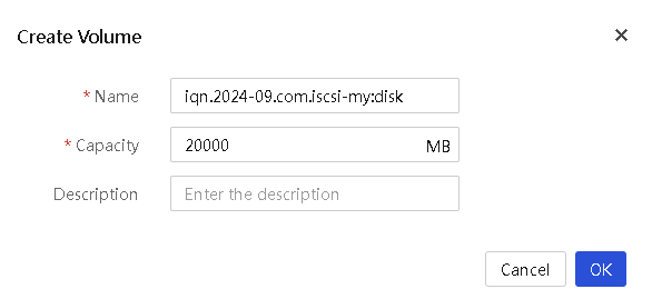
Copy a volume
About this task
Copy an existing iSCSI volume without any modification. After copying an iSCSI volume with a supported operating system installed, you can directly use the operating system.
The storage volume is completely copied, and the pure software packages installed in the storage volume are inherited. However, the hardware-related settings might vary with the system and hardware environments. Take the NIC settings as an example. If the source node and the target node both have the NIC with the same name, the NIC settings on the source node will take effect on the target node. If the source node uses a static IP, the target node must use the same static IP, which must be manually edited on the target node. If a storage volume is copied to a large number of target nodes, as a best practice, enable DHCP for IP address allocation.
After copying a volume with a VMware ESXi operating system installed, follow these restrictions and guidelines:
· As a best practice, separate the system partitions from the data partitions. Do not store the service data (for example, VM data) in the diskless boot volume. Otherwise, errors might occur after the volume is copied.
· A volume with a VMware ESXi operating system installed cannot be used across multiple blade servers.
· You can store data in a manually added iSCSI remote storage volume except the iSCSI boot volume in a VMware ESXi operating system. If you do this before copying the iSCSI volume, the added data storage configuration information will be lost after you copy the iSCSI volume. To re-connect to the remote volume, you must manually restore the connection.
· A copied VMware ESXi operating system might automatically reboot after the first boot. This is normal. The system can operate properly after the second reboot.
Procedure
|
|
IMPORTANT: To ensure complete data consistency on the source node and target node, as a best practice, copy the storage volume when the source node is not running any services or is shut down. |
To copy a volume:
1. In the navigation pane, select Menu > Templates > Diskless Boot to enter the page as shown in Figure 185.
Click Copy Volume, and click ![]() in the
upper right corner of the volume to copy.
in the
upper right corner of the volume to copy.
2. In the dialog box that opens as shown in Figure 187, enter the volume name. The size of the volume generated through copying is the same as that of the copied volume, and cannot be edited.
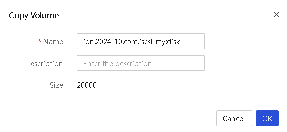
3. Click OK to start copying. Copying an iSCSI volume takes a period of time. Do not switch to any other pages during the copying process.
Delete a volume
About this task
Perform this task to delete an existing iSCSI volume.
Procedure
1. In the navigation pane, select Menu > Templates > Diskless Boot to enter the page as shown in Figure 185.
2. Click Delete Volume.
Click the ![]() icon in the upper right corner of the storage volume to delete.
icon in the upper right corner of the storage volume to delete.
3. In the dialog box that opens, click OK to delete the storage volume.
Set authentication
About this task
Set the iSCSI CHAP authentication information, which is used for authenticating an iSCSI client connecting to the iSCSI storage volume.
Procedure
1. In the navigation pane, select Menu > Templates > Diskless Boot to enter the page as shown in Figure 185.
2. Click ![]() or
or ![]() following
the Require Authentication field for an iSCSI
volume.
following
the Require Authentication field for an iSCSI
volume. ![]() indicates authentication is set.
indicates authentication is set. ![]() indicates
authentication is not set.
indicates
authentication is not set.
3. In the dialog box that opens, select Enable Authentication and enter the username and password for the storage volume. The iSCSI CHAP authentication password is a string of 12 to 16 characters.
4. Click OK.
Figure 188 Authentication settings
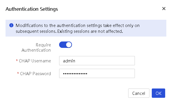
Deploy servers
Apply enclosure templates
Perform this task to apply an enclosure template to enclosures.
After an enclosure template is applied to an enclosure, UniSystem binds the server templates to the blade server slots according to the settings in the enclosure template. Whenever a server is installed in a slot of the enclosure, UniSystem automatically configures the server by using the bound server template when UniSystem runs in AE modules.
After applying an enclosure template to an enclosure, UniSystem automatically creates an enclosure configuration file for the enclosure based on the applied template.
For each blade server slot that is bound to a server template through application of an enclosure template, UniSystem creates an enclosure slot configuration file.
If the server to which the server template will be applied is not managed by UniSystem, UniSystem adds the server to the managed service list before applying the bound template to it.
Apply an enclosure template to enclosures
Restrictions and guidelines
In an enclosure template, you can bind two server templates to the two half-width slots in a full-width slot area. If a full-width blade server is installed in the full-width slot, UniSystem applies the server template bound to the half-width slot on the left side to the server.
For the connection settings function in an enclosure template to take effect, you must preconfigure VC before applying the enclosure template.
If a slot of an enclosure is bound to a server configuration template that contains the VC configuration, the VC configuration will take effect only when the enclosure configuration template or file is applied. If you apply the server configuration template directly, the VC configuration does not take effect.
Do not perform the following tasks when applying a configuration template:
· Power off or restart the device.
· Use KVM to perform mounting operations.
If the configuration contains other settings besides HDM settings, make sure the enclosure to which the template is applied is shut down.
If the HDM settings contain power capping settings, applying the template might cause the enclosure to be shut down.
Procedure
1. In the navigation pane, select Menu > Deployment > Enclosures > Apply Enclosure Templates.
Figure 189 Apply Enclosure Templates page
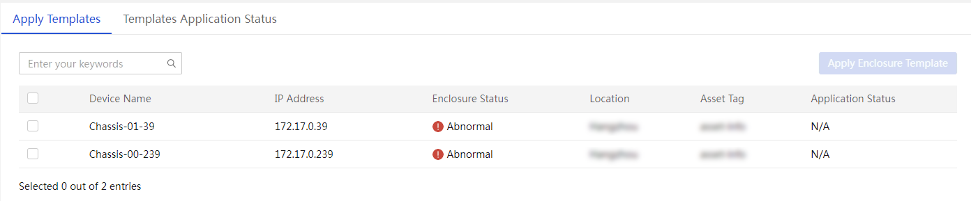
2. Select the target enclosures, and click Apply Enclosure Templates. The Apply Enclosure Templates dialog box opens.
Figure 190 Apply Enclosure Template dialog box
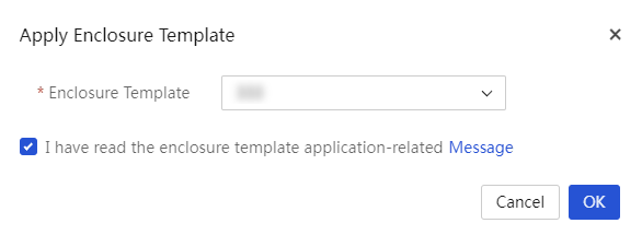
3. Select an enclosure template you want to apply to the selected enclosures and select I have read the enclosure template application-related Message.
4. Click OK.
The Template Application Status tab opens, displaying the template application status and progress.
5. To view template application information about a server, click Logs in the Actions column for the server.
Enclosure configuration files
About this task
After applying an enclosure template to an enclosure, UniSystem automatically generates an enclosure configuration file for the enclosure based on the applied template.
In an enclosure template, you can bind two server templates to the two half-width slots in a full-width slot area. If a full-width blade server is installed in the full-width slot, UniSystem applies the server template bound to the half-width slot on the left side to the server.
The enclosure configuration file contains all the settings in the enclosure template. You can edit the settings in the enclosure configuration file, and then apply the edited file to the enclosure as needed.
Procedure
1. In the navigation pane, select Menu > Deployment > Enclosures > Enclosure Config Files.
Figure 191 Enclosure configuration files
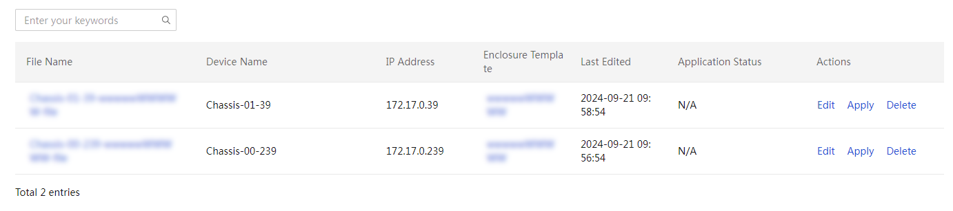
2. Click a file name to view detailed information about the selected enclosure configuration file.
3. (Optional.) To edit an enclosure configuration file, click Edit in the Actions column for the target file. In the dialog box that opens, edit the settings and then click Save.
Figure 192 Editing an enclosure configuration file
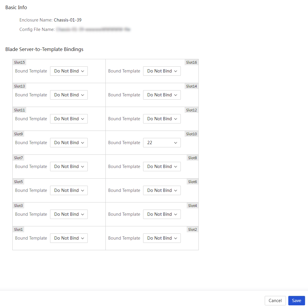
4. Click Apply in the Actions column for the enclosure configuration file you want to apply. In the dialog box that opens, click OK.
5. (Optional.) To delete an enclosure configuration file, click Delete in the Actions column for the target file. In the dialog box that opens, click OK.
Enclosure slot configuration files
About this task
UniSystem automatically creates an enclosure slot configuration file for each blade server slot that is bound to a server template through application of an enclosure template.
You can edit the settings in the enclosure slot configuration file, and then apply the edited file to the blade server as needed.
If an enclosure slot configuration file (or enclosure configuration file) is automatically applied after a node is unplugged and plugged, the VC configuration uses the policy file on the OM.
Procedure
1. In the navigation pane, select Menu > Deployment > Enclosures > Enclosure Slot Config Files.
Figure 193 Enclosure slot configuration files

2. Click a file name to view detailed information about the selected enclosure slot configuration file.
3. (Optional.) To edit an enclosure slot configuration file, click Edit in the Actions column for the target file. In the dialog box that opens, edit the settings and then click Save.
Figure 194 Editing an enclosure slot configuration file
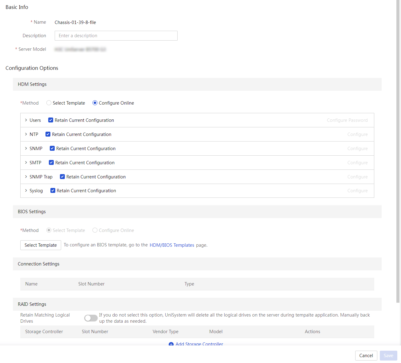
4. Click Apply in the Actions column for the enclosure slot configuration file you want to apply. In the dialog box that opens, click OK.
5. Click Logs in the Actions column for the enclosure slot configuration file to view its application logs.
6. (Optional.) To delete an enclosure slot configuration file, click Delete in the Actions column for the target file. In the dialog box that opens, click OK.
Apply server templates
Apply a server template to servers
Perform this task to apply a server template to servers. By applying a server template to a server, UniSystem deploys the HDM, BIOS, connection, RAID, and OS installation settings in the template to the server.
|
|
IMPORTANT: · To use this feature, you must add HDM server nodes to UniSystem first. For more information, see "Manage servers." · To install an OS on a server by using a template with a cloned image or through UniSystem 2.00.26 or earlier, a server must be able to communicate with UniSystem through the system IP address of iFIST. iFIST obtains its system IP address from the DHCP server, which must reside on the same LAN as the server. · As of version 2.00. 26, this feature can work with HDM (HDM 2.11 or later) and iFIST (iFIST 1.01.26 or later) to implement out-of-band OS installation. · On a server running HDM of a version earlier than HDM 2.11 and iFIST of a version earlier than 1.01.26, version 2.00.26 can install an OS by communicating with iFIST on the server. |
Restrictions and guidelines
· If the configuration contains other settings besides HDM settings, make sure the server to which the template is applied is shut down.
· If the HDM settings contain power capping settings, applying the template might cause the server to be shut down.
· Before applying a template to servers, make sure no operations are in progress on the servers. During the template application process, do not perform other operations contained in the settings.
· During the template application process on a server, do not perform the following operations:
¡ Power off or reboot the server.
¡ Update, reset, or restore the factory defaults for HDM on the server.
¡ Perform mount operations through KVM.
· The privilege to apply HDM settings depends on the network privilege of the HDM account. Make sure the user has the privilege to this operation.
· After the HDM settings are successfully applied to a target server, the server will automatically reboot. The HDM status will restore in several minutes.
· To successfully apply the HDM or BIOS settings to a server, make sure the HDM or BIOS version in the template is the same as the HDM or BIOS version of the server.
· When you apply HDM settings of version HDM-1.11.19 or earlier (including all HDM-1.10.XX versions), the configuration import policy of UniSystem is the same as that of HDM. If the HDM settings are copied to multiple servers, the server HDM IPs might conflict. Use this feature with caution.
· When you apply HDM settings of version HDM-1.11.20 or later, UniSystem does not edit the HDM IP settings. To avoid IP conflicts, do not configure the same IP address for multiple HDMs.
· When you apply an HDM template to servers, the IP settings, VLAN settings, and LLDP settings in the HDM template will not take effect in UniSystem of version UniSystem-2.31 or later.
· UniSystem supports only LSI storage controllers operating in RAID mode (some LSI storage controllers do not require operating mode configuration).
· As a best practice, do not install an OS through applying a template on a disk of 2TB or larger. Such an installation might fail.
· To install an operating system on a physical drive of a server through a template successfully, make sure the server has iFIST of version iFIST-1.01.25 or later installed.
· You can clone the operating system of a server to another server by applying a server template that contains the cloned image of the source server to the target server. Follow these guidelines when you perform this operation:
¡ Make sure the target server and the source server of the cloned image have matching hardware components.
¡ The IP address settings specified in the template will be applied to the first server port connected to UniSystem. The remaining network ports on the server use the settings in the cloned image file.
¡ For the Linux system, the partition settings of the source server will be copied to the target server through the cloned image.
¡ For the VMware ESXi system, data partitions must be manually created in the system drive on the target server. VMware ESXi 7.0U2 (64 bit) and higher versions do not support setting the IP address and host name.
· If you update the REPO from HDM and have not restarted a server after the update is executed, you might fail to apply the RAID settings or OS settings to the server through a server template. To resolve this issue, first restart the server to complete the REPO update and then apply a server template to the server.
· The automatic shutdown feature is available only when you configure repeat settings for the timer settings.
· If only HDM settings are configured in the template configuration, the automatic shutdown feature will not power off the server.
· Repeated application of a template might change the current configuration of the server. Please be cautious.
Procedure
1. In the navigation pane, select Menu > Deployment > Servers > Apply Server Templates to enter the page as shown in Figure 195.
Figure 195 Applying server templates
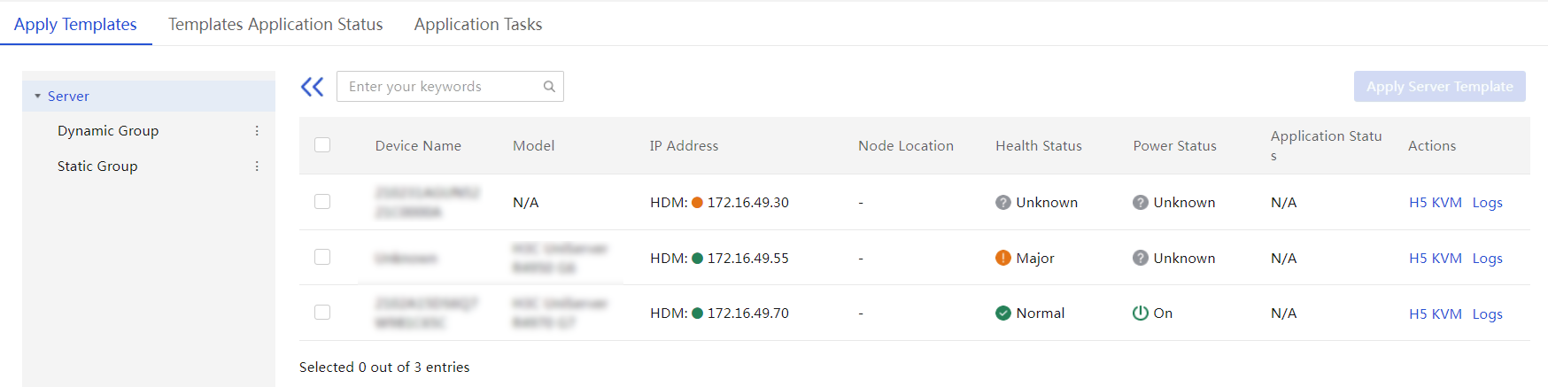
2. Select the target servers, and click Apply Server Templates. On the page that opens, perform the following tasks.
To quickly filter out the target server, you can use the static group and dynamic group from the left navigation pane or enter a keyword in the search area.
3. In the dialog box that opens as shown in Figure 196, perform the following tasks:
a. Select the server template to apply and verify the device name and device status.
b. Configure timer settings.
- If you select custom settings for timer settings, specify the execution time in the Timer Settings field. UniSystem will start deployment at the scheduled time.
- If you select repeat settings for timer settings, specify the update frequency and update time, and enable Auto Shutdown Before Application as needed. UniSystem will deploy the template as configured.
- If you select Execute Now for timer settings, UniSystem starts deploying immediately when you click OK.
Figure 196 Applying a server template
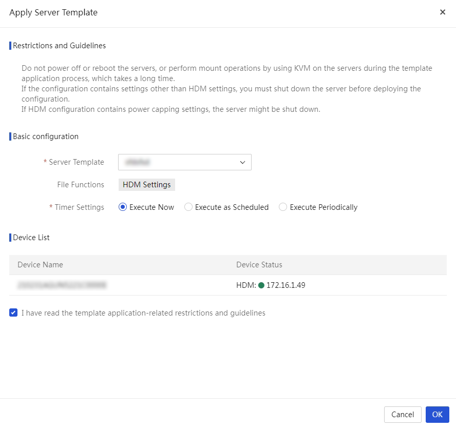
4. Set scheduled deployment. If you enable scheduled deployment, you can select the scheduled time from the Execution Time field. UniSystem will start deployment at the scheduled time. If you disable scheduled deployment, UniSystem immediately starts deployment after you click OK.
5. Select I have read the template application-related restrictions and guidelines.
6. Click OK to start applying the template to the selected servers.
The Template Application Status tab opens, displaying the template application status and progress.
7. To view detailed template application information about a server, click Logs in the Actions column for the server.
8. If you enable scheduled deployment, the application task page opens after the template is applied. On this page, you can see the task execution state.
¡ To stop an application task, click Stop in the Actions column for that task.
¡ To delete an application task, click Delete in the Actions column for that task.
Server configuration files
A server configuration file is a configuration file generated for a single server after a server template is successfully applied. For how to apply a server template, see "Apply server templates."
You can edit the server configuration file of a server and then apply it to the same server again. This feature allows you to fast edit the configuration of a server without editing a server template.
View a server configuration file
In the navigation pane, select Menu > Deployment > Servers > Server Config Files to view the server configuration files in UniSystem.
Figure 197 Server configuration files
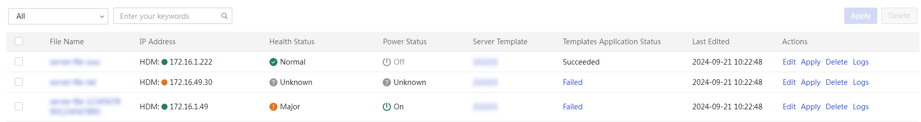
Edit a server configuration file
Restrictions and guidelines
When the IP address, subnet mask, or gateway is modified in the OS settings of a server configuration file, the IP address that the server template assigned to the server is withdrawn. The withdrawn IP address can be assigned to another server by the server template.
Procedure
1. In the navigation pane, select Menu > Deployment > Servers > Server Config Files.
2. Click Edit in the Actions column for the server configuration file to be edited. On the page shown in Figure 198, edit the server configuration file as needed.
Figure 198 Editing a server configuration file
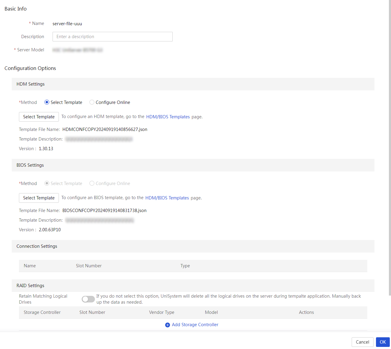
3. Review the configuration file change, and click OK.
Apply server configuration files
Restrictions and guidelines
If the application status of a server configuration file is Failed, see the application logs to obtain more information about the server configuration file.
Procedure
1. In the navigation pane, select Menu > Deployment > Servers > Server Config Files to enter the page shown in Figure 199.
Figure 199 Server Config Files page
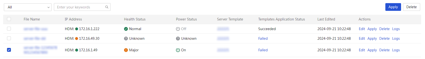
2. Perform either of the following steps:
¡ To apply a single server configuration file, click Apply in the Actions column for the server configuration file to be applied.
¡ To bulk apply server configuration files, select the server configuration files to be applied, and click Apply in the upper right corner.
3. In the dialog box that opens, click OK to confirm the operation.
Delete server configuration files
Restrictions and guidelines
When a server configuration file of a server is deleted, the IP address that the server template assigned to the server is withdrawn. The withdrawn IP address can be assigned to another server by the server template.
Procedure
1. In the navigation pane, select Menu > Deployment > Servers > Server Config Files.
2. Perform either of the following steps:
¡ To delete a single server configuration file, click Delete in the Actions column for the server configuration file to be deleted.
¡ To bulk delete server configuration files, select the server configuration files to be deleted, and click Delete in the upper right corner.
3. In the dialog box that opens, click OK to confirm the operation.
Update components
From this menu, you can update the components of the local nodes and remote nodes. The components include HDM, BIOS, CPLD, and firmware and drivers for some hardware.
A local node refers to the UniSystem server. The local task contains only local nodes. The Update Components page will automatically add a local task named localhost. The local task cannot be deleted.
The remote nodes refer to the managed servers. The remote nodes include HDM and FIST SMS.
|
|
TIP: When the HDM version is between HDM-1.11.08 and HDM-1.30.18 for a server, if you use a REPO to upgrade the BIOS firmware through FIST SMS on UniSystem, the BIOS settings cannot be retained. |
Add a task
About this task
Perform this task to add multiple managed servers to a task, so that you can bulk update the server nodes.
Procedure
1. In the navigation pane, select Menu > Deployment > Servers > Update Components.
Node localhost is the host where the UniSystem server software is installed. When UniSystem is being installed on a server, the task named localhost is automatically created. The task named localhost cannot be deleted. Another local task named localhost cannot be added.
Figure 200 Updating components
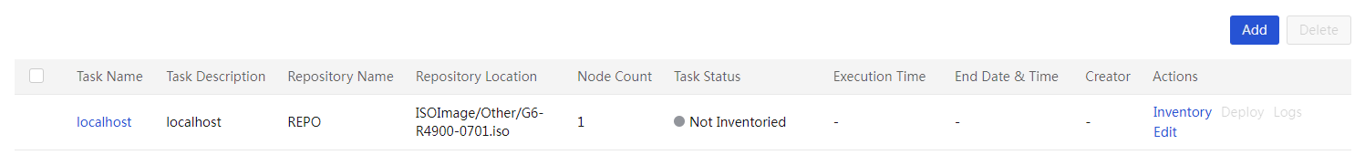
2. Click Add to enter the page as shown in Figure 201. On this page, perform the following steps:
a. Enter the task name and description.
b. Select the target server nodes. You can use one of the following methods to quickly search for nodes:
- Enter the management IP address of HDM for a node in in the IP address bar.
- Click Download Template to download a file template and specify the management IP address of HDM for a node in the file template. Then, click Upload File to upload the template.
c. To add a VMware component update task, click File Template link to download the template. Fill in the HDM management IP, VMware OS IP, and root username and password of VMware OS. Then, click Upload File to up load the template file.
d. Select the repository to be assigned to the servers from the Repository list.
e. In the Installation Options area, configure the HDM/BIOS firmware configuration retention policies and the server restart policy.
f. In the Execution Settings area, configure the version compliance check.
3. Click Save and Inventory.
4. After the inventory, perform the following operations as needed:
¡ If Execute Now or Execute as Scheduled is selected for the task, view component information and select components, and click Deploy. Then, the system will immediately start to update the components or start to update components as scheduled.
¡ If Execute Periodically is selected for the task, view component information and click OK. The task is created successfully.
¡ To edit the task, click Back to Edit.
5. After deployment, click Logs. In the dialog box that opens, you can view the task deployment log.

Inventory and deploy a task
About this task
Perform the following tasks to update components for nodes in a task:
· Inventory a task: Obtain information about each node in the task, and then filter out components applicable to the nodes from the repository. Before inventorying a task, make sure all repositories bound to the task have been inventoried.
· Deploy a task: Install the components to update on the nodes in the task.
Procedure
1. In the navigation pane, select Menu > Deployment > Servers > Update Components.
2. Click Inventory in the Actions column for the target task. In the dialog box that opens, select the target repository from the Repository list.
Figure 202 Inventorying a task
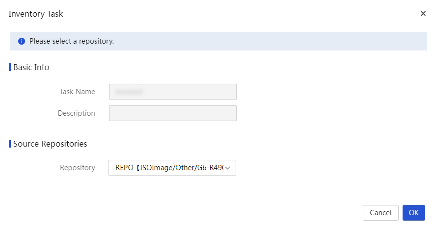
3. To terminate the inventory during the process, click Abort, UniSystem will complete the inventory of the components being processed on each node, and then terminate the inventory of the remaining components on each node.
4. As shown in Figure 203, after inventorying is completed, the Deploy link appears. The local task named localhost cannot be deployed together with other tasks.
|
|
IMPORTANT: · Failure to inventory or deploy components on some nodes in the task does not affect the whole inventorying and deployment process. · When a task is being inventoried or deployed, UniSystem will automatically skip nodes in abnormal state in the task. If all nodes in a task are in abnormal state, you cannot inventory or deploy the task. |
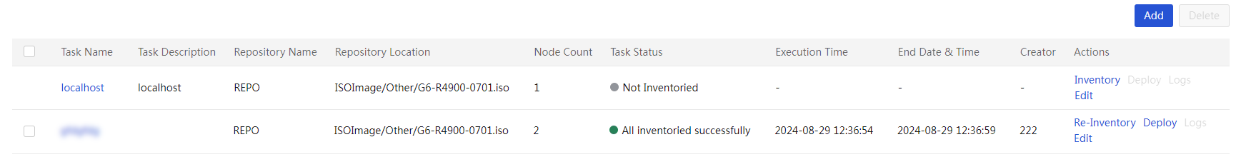
5. Click Deploy. The page as shown in Figure 204 opens. Check the component version to determine whether to update the component. Click the name of a component to view the component details. According to the dependent items of the component, determine whether you need to update the dependent components of the current component. Also, determine whether the target component needs a reboot to take effect.
|
|
IMPORTANT: When you select Restart HDM Immediately After Update, deploy HDM update separately to avoid affecting other component deployments if the current HDM version is in the HDM-2.XX format and is earlier than HDM-2.96. |
6. Set scheduled deployment. If you enable scheduled deployment, you can select the scheduled time. UniSystem will start deployment at the scheduled time. If you disable scheduled deployment, UniSystem immediately starts deployment after you click OK.
|
|
IMPORTANT: · When using the scheduled deployment function, make sure the browser time is the same as the server time to avoid time disorder. · For a task with scheduled deployment enabled, the related repository and task will be automatically inventoried after UniSystem is restarted. |
7. Click OK to start the deployment.

8. To terminate the deployment during the process, click Abort Deploying. UniSystem will complete the deployment of the components being processed on each node, and then terminate the deployment of the remaining components on each node.
9. As shown in Figure 205, after the deployment is completed, click Logs to view the deployment logs.
Figure 205 Deployment completed
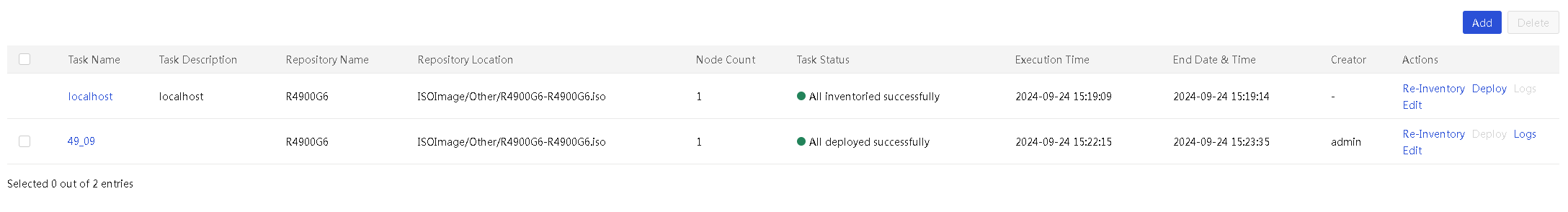
10. As shown in Figure 206, enter the task deployment log page to view the component deployment results.
Figure 206 Task deployment logs
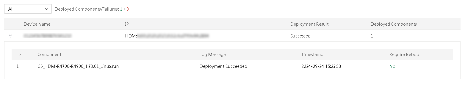
View task details
About this task
By viewing the task details, users can easily and intuitively understand the specifics of component update tasks, including node deployment status and execution details. This helps users comprehensively grasp the update status of node components.
Restrictions and guidelines
You can reboot HDM for a node only when all components on that node failed to be deployed.
Procedure
1. In the navigation pane, select Menu > Deployment > Servers > Update Components. On this page, you can view all tasks.
2. Click the link in the Task Name column for the target task. The basic information, execution list, node list, installation options, and execution settings of the task are displayed.
3. (Optional.) You can view the inventory logs, deployment logs, export reports, and restart HDM in the execution list.
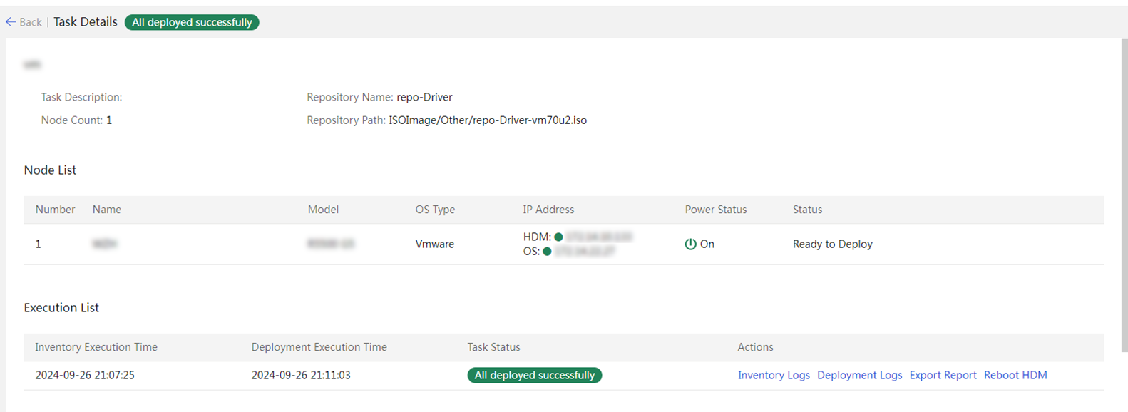
Edit a task
1. In the navigation pane, select Menu > Deployment > Servers > Update Components.
2. Click Edit in the Actions column for the task to edit. In the dialog box that opens, perform the following steps:
a. In the Basic Info area, edit the task description.
b. In the Select Nodes area, select the nodes to be edited.
c. In the Repository area, select the repository to be assigned to the task from the Repository list.
d. In the Installation Options area, edit HDM/BIOS firmware configuration retention policies and the server restart policy.
3. Click OK.
Troubleshooting issues
No result displayed after task inventorying
Symptom
The system does not display the inventorying result when a task is inventoried for component update.
Cause
· The user does not run UniSystem as an administrator or root user.
· The firewall is not disabled in the operating system where the UniSystem server or FIST SMS runs.
Action
1. Run UniSystem as an administrator or root user. In Windows, right-click the FistLaunch_x64.bat file and select Run as administrator. In Linux, switch to the root user to run UniSystem.
2. Verify that the firewall is disabled in the operating system. If the firewall is enabled, disable the firewall and perform task inventorying again.
3. If the issue persists, contact Technical Support.
Current component version displaying as Unknown during task deployment for component update
Symptom
The current component is displayed as Unknown during task deployment for component update.
Cause
UniSystem fails to obtain the current server component version.
Action
No action is required. After deployment, you can examine the component version to identify whether the component update is successful.
Insufficient HDM user privilege
Symptom
Deployment failed for component update and the reason is that the HDM user does not have the privilege.
Cause
The HDM user of the servers does not have administrator privilege.
Action
Edit devices on the Servers page, and specify the new username and password of the HDM user as an administrator.
Software requirements not met in the operating systems
Symptoms
Deployment failed for component update, and a message indicates that the dependent software is not installed.
Cause
When you update components through FIST SMS, the dependent software in the operating system for the update is not installed, for example, GNU Compiler Collection (GCC).
Action
Install the software as instructed in the operating system where FIST SMS resides.
UniSystem cannot connect to servers
Symptom
Deployment failed for component update, and the reason is that a login failure occurred.
Cause
· An error occurred on network connection between the UniSystem server and HDM.
· The username or password is incorrect for login to HDM or FIST SMS.
Action
1. Verify that the servers are powered on correctly and the network connection is normal
2. View server information, and edit devices on the Servers page to specify correct username and password for as required.
Component deployment failed
Symptom
Deployment failed for component update, but no reason is displayed.
Cause
· The Python environment is not installed when you update drive firmware through FIST SMS.
· Firmware of some components has protection mechanism and does not support repeated update, for example, PMem 200 memory, and Rack_NIC-360T-B2 and Rack_NIC-560F-B2 network adapters.
· For firmware or driver update through FIST SMS, the update fails because the original driver version of components is too low.
Action
1. If deployment failed on drive firmware, verify that Python is installed in the operating system and the Python environment is normal.
|
|
IMPORTANT: If multiple Python versions are available, execute the ln –s or update-alternatives command to specify the default Python version. For example: · ln -s /usr/local/python3/bin/python3.7 /usr/bin/python. · sudo alternatives --set python /usr/bin/python3. |
2. Restart the operating system to make the last deployment take effect.
3. Identify the driver version of the components that failed deployment, and manually update the driver as needed.
4. If the issue persists, contact Technical Support.
Update the firmware
|
|
NOTE: · To use this feature, you must add HDM server nodes to UniSystem first. For more information, see "Manage servers. · Do not perform template application, component update, or other operations on a server while firmware update is in progress on the server. · Before upgrade, as a best practice to ensure that the firmware can be upgraded to the expected version, first check the related firmware version information in the REPO. |
UniSystem supports the following methods to update the firmware:
· Offline firmware update—This method automatically updates the firmware on multiple servers in bulk by using the REPO (containing the LiveCD system) uploaded to UniSystem. This method will affect the operation of the original operating system.
· HDM out-of-band firmware update—This method updates the REPO by using HDM out-of-band management and automatically accesses iFIST to perform firmware update at the next server startup.
Update the firmware offline
About this task
You can perform unattended firmware update on multiple servers in bulk.
Before you use this function, upload the REPO (ISO file) containing the LiveCD system to UniSystem. For information about the operation procedure, see "Manage images."
Restrictions and guidelines
· To ensure successful update, verify that the target server does not have an image mounted through KVM and its USB port is not connected to the USB drive.
· To guarantee the firmware update speed, use the HDM dedicated port as a best practice. If the shared network port is used, set the rate of the corresponding NIC on the UniSystem server to 100 Mbps.
· Keep the network stable during the update process.
· To abort the ongoing update process on a server and start a new update process, select the server, and then click Cancel Update first.
· An HDM server node in abnormal state cannot be rebooted.
· UniSystem can show the firmware update progress and result for a server only when a repository is used for the update and the server runs HDM 2.11 or later.
Procedure
1. In the navigation pane, select Menu > Deployment > Servers > Firmware Update > Offline Firmware Update.
2. Select the target servers, and then click Update Firmware.
To quickly filter out the target server, you can use the static group and dynamic group from the left navigation pane or enter a keyword in the search area.
3. In the dialog box that opens, select the image file for the update, and then click OK.
4. (Optional.) To view the firmware update progress of a server, click the H5 KVM link in the Actions column for the sever.
5. (Optional.) After the update is complete for a server, click the Update Finished or Update Failed link in the Update Status column for the server to view the update result.
6. Some firmware products require a reboot to take effect. Select the updated servers and click Reboot to reboot the servers.
Figure 208 Offline firmware update
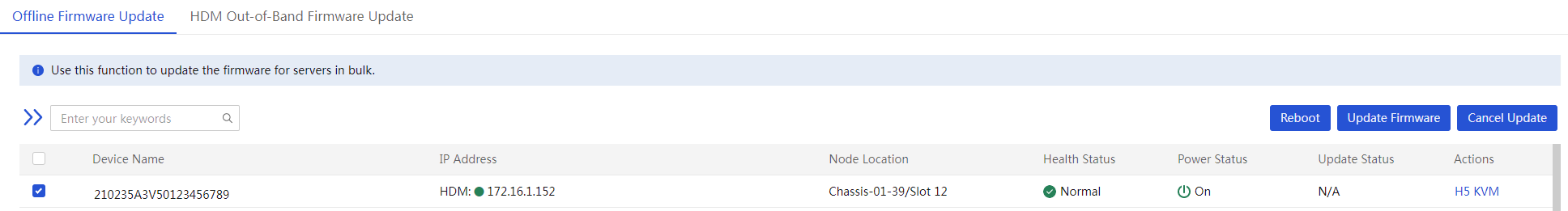
Update the firmware by using HDM out-of-band management
About this task
You can use HDM out-of-band management to update the REPO on multiple servers in bulk.
Before you use this function, upload the REPO to UniSystem. For information about the operation procedure, see "Manage images."
To use this feature, the following requirements must be met:
· UniSystem is used together with HDM and iFIST.
· UniSystem is in UniSystem-2.32 or later versions.
· HDM is in HDM-2.52 or later versions.
· iFIST is in iFIST-1.32 or later versions.
The Update Configuration and Update Options fields are not available for G6 servers. For the new version to take effect, you must restart the server manually after the update
Procedure
1. In the navigation pane, select Menu > Deployment > Servers > Firmware Update > HDM Out-of-Band Firmware Update.
Figure 209 HDM Out-of-Band Firmware Update
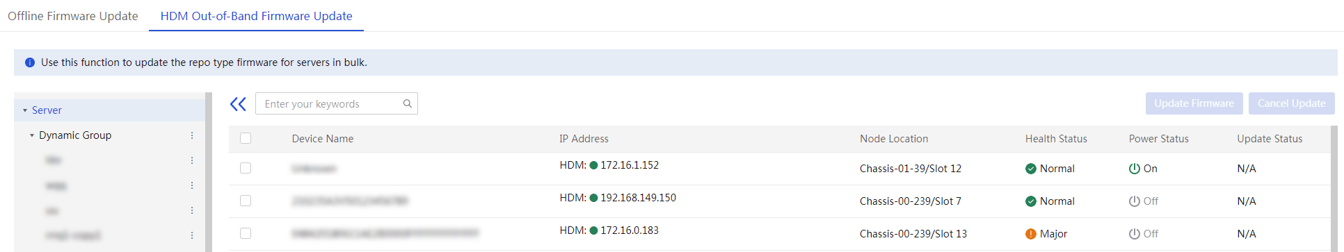
2. Select the target servers and then click Update Firmware. In the dialog box that opens, select the image file for the update, the server restart method after firmware update, and an update option.
To search for the target servers, select a static group or dynamic group from the left navigation pane or enter a keyword in the search box.
Figure 210 Configuring parameters
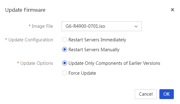
3. Click OK.
4. To cancel ongoing firmware update operations on servers, select the target servers and then click Cancel Update. In the confirmation dialog box that opens, click OK.
If a server is verifying the file for update, you cannot cancel the ongoing firmware update operation on the server.
Secure erase
When a server stops running due to the end of its lifecycle or other reasons, you can use the secure erase feature to erase the server's HDM, BIOS, and storage data to prevent user data leakage. If the data to be erased is large in capacity, the data erase process may take a long time (a day or longer).
This feature supports batch secure erase operations on servers without manual intervention. The erase process is automated, and the erase results will be displayed.
|
|
CAUTION: · Please use the secure erase feature with caution. Before using this feature, make sure the data to be erased is useless and can be safely erased. Otherwise, back up the data in advance to prevent any loss of important information. · Before starting the data erase, make sure to remove all external storage devices (including but not limited to external drives) connected to the servers to avoid accidentally erasing data. · During the process of erasing storage data, the server will automatically restart and enter iFIST to perform the erase operation. After the erase is completed, the server will restart again and enter the system startup item before the erase process. · To ensure successful erase, before starting the data erase, make sure the iFIST software version for the target server is not lower than iFIST-1.58, and the HDM software version is not lower than HDM2-1.57. · After erasing the HDM data, the HDM management IP address will be restored to the default address. This may prevent users from performing other operations on the server through UniSystem. |
To perform secure erase:
1. In the navigation pane, select Menu > Deployment > Servers > Secure Erasure.
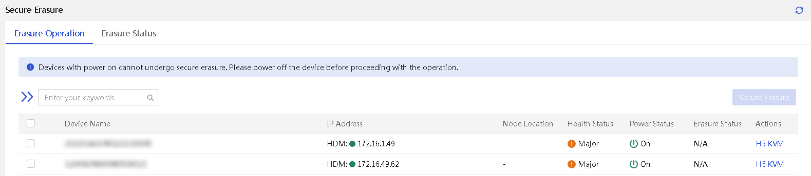
2. To search for the target servers, select a group, and enter a keyword in the search box.
3. Select a target server, click Secure Erasure. Select items from HDM, BIOS, and Storage to be erased.
Figure 212 Selecting the erase options
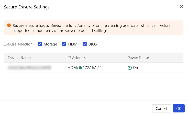
4. Click OK. In the dialog box that opens, enter the UniSystem login password.
5. Click OK. UniSystem will verify the password and start erasing the data after the verification passes.
6. After starting to erase data, the page automatically jumps to the Erasure Status tab to display the status and progress of the current server erase operation. The available erase results and methods for the erase to take effect are shown in Table 20.
|
Item |
Erase result |
Method to take effect |
|
HDM |
Restore HDM factory defaults. SDS logs and flash card data are erased. |
HDM restarts automatically. |
|
BIOS |
· Restore to the BIOS default settings. · The administrator and user passwords for the BIOS are erased. The BIOS does not require a password for the user whose password is erased to enter the BIOS Setup utility at next restart. · The server power-on password is erased from the BIOS. |
Restart the server. |
|
No-volatile DRAM (NVDIMM) |
Data in NVDIMMs that are not in memory mode are erased. After erase, all NVDIMMs operate in memory mode. |
The server restarts automatically. |
|
Storage controller |
· All logical drives managed by the RSTe RAID controller and VROC module are deleted. · All logical drives managed by the following LSI storage controllers are deleted: · If the LSI controller operates in RAID mode before the erasure, the JBOD attribute of the RAID mode is changed to ON once the erasure operation finishes. ¡ HBA-LSI-9311-8i ¡ HBA-LSI-9500-16i ¡ HBA–LSI-9500-8i ¡ HBA-LSI-9540-8i · All logical drives managed by the following PMC storage controllers are deleted: ¡ HBA-H460-B1 ¡ RAID-P4408-Mf-8i-2GB ¡ RAID-P2404-Mf-4i ¡ RAID-P460-B2 ¡ RAID-P460-B4 · All logical drives managed by the following MARVELL storage controllers are deleted: ¡ RAID-MARVELL-SANTACRUZ-2i |
The server restarts automatically. |
|
Drive |
All data in the drive are deleted. |
The server restarts automatically. |
|
SD card |
All data in the SD card are deleted. |
The server restarts automatically. |
Server software license management
This feature supports bulk management operations for HDM licenses on G6 and later servers, including viewing, exporting, installing, and uninstalling.
A license refers to the legal permission granted by a server manufacturer to a user for using specific software features. For a list of features requiring HDM licensing and their properties, see H3C HDM Management Software License Matrixes. For more information about how to obtain licenses, see H3C Servers HDM Licensing Guide.
· Obtain the license activation file from an official channel of the server manufacturer.
· Before installing a license activation file, make sure the DID code of the target server is consistent with the DID code of the requested license activation file.
· Before installing an officially authorized license activation file, make sure the license of the server is in one of the following states:
¡ The server is not installed with the activation file for another official license or trial license.
¡ If an official license has been installed, first uninstall the license and export the license uninstallation file.
¡ If a trial license has been installed, first uninstall the license activation file.
· Before installing an activation file, make sure the server is not installed with a license activation file, and the license corresponding to the activation file is within the valid period.
After uninstallation, UniSystem automatically packages and exports the uninstallation files for the official licenses on all devices from which the licenses have been successfully unmounted.
Procedure
1. In the navigation pane, select Menu > Deployment > Servers > Manage Server Software Licenses.
Figure 213 Server software license management page
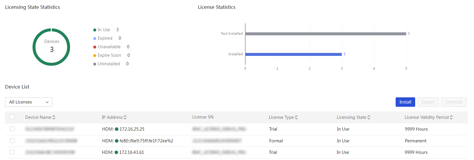
2. View the licensing status of the server.
3. To filter information by license status, select a status option in the Device List section.
4. To export summary server software license information, select the target servers, and then click Export.
5. To install licenses, click Install. The bulk license installation page opens.
b. Click Install to start the HDM license installation.
c. After installation, click Finish.
Figure 214 License installation page
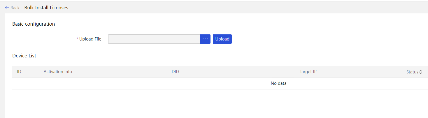
6. To uninstall licenses, select the target servers, and then click Uninstall.
a. Enter the password of the current UniSystem user.
b. Click OK. UniSystem then verifies the password. Once verification passes, UniSystem begins to uninstall the license.
Figure 215 Confirming license uninstallation
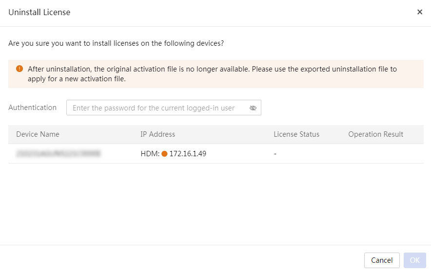
Parameters
· Device Name: Name of the server.
· IP Address: HDM management IP address of the server.
· License Serial Number: Serial number of the license.
· License Type:
¡ Formal : You can obtain an official license only through an official channel of the server manufacturer. Official licenses support installation, uninstallation, and migration, and is permanently valid.
¡ Trial: You can contact the technical support of the server manufacturer to obtain a trial license. Trial licenses support installation and uninstallation, but do not support migration, and is valid for 90 days. To use specific software features after the trial license expires, purchase and install an official license in time.
· License Status:
¡ In Use: The license activation file is functioning properly.
¡ Expired: The license activation file has expired.
¡ Unavailable: The license activation file is unavailable. Please contact Technical Support.
¡ Expire Soon: The license activation file is about to expire.
¡ Uninstalled: The license activation file has been uninstalled.
¡ Not Installed: The server does not have a license activation file installed.
· License Validity Period: The expiration date of the license activation file.
· DID: Device identification code (DID) for the server.
· Target IP: The HDM management IP address of the server on which the license will be installed.
· Status: Installation status of the license, including Being Installed, Successed, and Failed.
Server diagnostics
|
|
NOTE: Only the default admin user and users with the administrator role and permissions over all resources support this feature. |
This feature supports bulk execution of fast diagnosis and stress testing servers, scans the components on the servers, collects and organizes information on each component, and diagnoses the working and health status of each component. This makes it easier to troubleshoot problems in a timely manner, reduce device usage risks, and export diagnostic reports.
You can download and view reports to analyze the status and performance of servers and their components.
View the diagnostic task list
Restrictions and guidelines
· You can cancel a task that has not started and is still within the execution period.
· You can terminate a task in In Progress state.
· You cannot edit ongoing tasks, including tasks in progress, non-canceled scheduled tasks, and non-canceled periodic tasks.
· You cannot delete non-started tasks, tasks in progress, or incomplete periodic tasks.
Procedure
1. In the navigation pane, select Menu > Deployment > Servers > Server Diagnostics.
2. View the added tasks and brief task information.
3. To edit, cancel, terminate, and delete a task, or download a report for a task, click the corresponding buttons in the Actions column for that task.
Figure 216 Server diagnostics
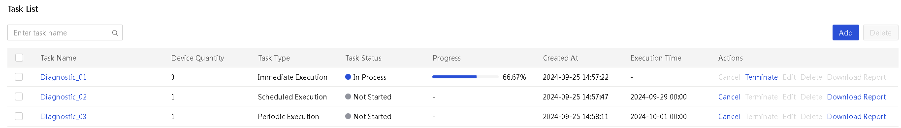
Parameters
· Task Name: Name of the task.
· Device Quantity: Total number of devices included in the task.
· Task Type: Task execution mode, including Immediate Execution, Scheduled Execution, and Periodic Execution.
· Task Status: Current execution status of the task, including Not Started, In Progress, All Succeeded, Partially Succeeded, All Failed, Expired, and Canceled.
· Progress: Execution progress in percentage when the task is in progress.
· Created At: Time when the task was created or edited most recently.
· Execution Time: Time when the scheduled or periodic task was executed.
Configure a diagnostic task
|
|
NOTE: Only G6 and later servers managed by HDM support this feature. |
Add a diagnostic task
1. In the navigation pane, select Menu > Deployment > Servers > Server Diagnostics.
2. Click Add.
Figure 217 Adding a task
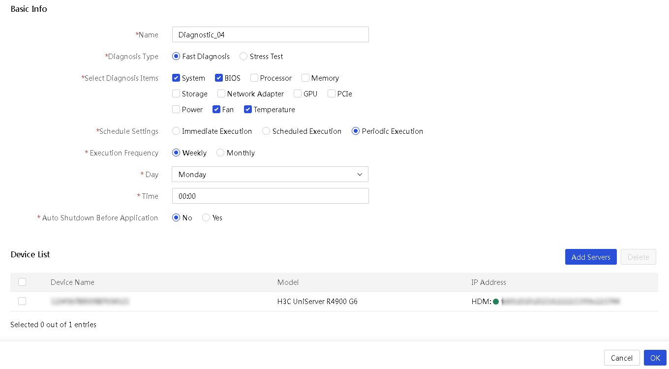
3. Configure basic task settings.
a. Enter the task name.
b. Select the diagnosis type and diagnosis items.
c. Configure task schedule settings.
- Immediate Execution: Executes the task immediately after the task is created.
- Scheduled Execution: Execute a diagnostic task once at a scheduled time. If this option is selected, configure the task execution time. After the task is added, the system will execute the diagnostic task on servers at the scheduled time.
- Periodic Execution: Specify the frequency to execute the periodic task and specify the action to take before the scheduled execution time.
4. Click Add Servers. On the page that opens, select the servers that need diagnostics and click OK.
5. Click OK.
Edit a diagnostic task
1. In the navigation pane, select Menu > Deployment > Servers > Server Diagnostics.
2. Click Edit in the Actions column for the target task.
3. Edit basic task settings.
4. Edit devices to be diagnosed:
¡ To add servers, click Add Servers. On the page that opens, select the servers that need diagnostics and click OK.
¡ To delete devices from the list, select the devces and then click Delete Device.
5. Click OK.
Delete diagnostic tasks
|
|
NOTE: · You cannot delete ongoing tasks, non-canceled scheduled tasks, or non-canceled periodic tasks. · Deleting a task will also delete the task-related reports. |
Procedure
1. In the navigation pane, select Menu > Deployment > Servers > Server Diagnostics.
2. Perform either of the following tasks to delete diagnostic tasks:
¡ To delete a diagnostic task, click Delete in the Actions column for that task.
¡ To bulk delete diagnostic tasks, select these tasks and click Delete in the upper right corner.
Parameters
· Name: Name of the server diagnostic task.
· Diagnosis Type: Select a server diagnosis type. Options include Fast Diagnosis and Stress Test.
· Select Diagnosis Items—Select the diagnosis items in the task.
¡ If Fast Diagnosis is selected, the available items include System, BIOS, Processor, Memory, Storage, Network Adapter, GPU, PCIe, Power, Fan, and Temperature.
¡ If Stress Test is selected, the available items include Processor, Memory, and Storage.
· Scheduled Settings: Set the execution settings for diagnostic tasks. Options include:
¡ Immediate Execution: Executes the task immediately after the task is created.
¡ Scheduled Execution: Execute a diagnostic task once at a scheduled time. If this option is selected, configure the task execution time. After the task is added, the system will execute the diagnostic task on servers at the scheduled time.
- Execution Time: Specify the time to execute the task.
¡ Periodic Execution: Specify the frequency to execute the periodic task.
- Execution Frequency: Options include Weekly and Monthly.
- Day/Date: Specify the execution date.
- Time: Specify the execution time.
- Auto Shutdown Before Application: Select whether to automatically shut down a server before the scheduled execution time.
¡ Device List: Specify the devices on which the task takes effect.
- Device Name: Server name.
- Model: Server model.
- IP Address: Server IP address.
View task details
Restrictions and guidelines
· To use H5 KVM, make sure the login account has the device management permission.
· After you upgrade UniSystem to version 2.72, the task details from the previous version might fail to display diagnostic items.
Procedure
1. In the navigation pane, select Menu > Deployment > Servers > Server Diagnostics.
2. Click the name link for a task to view the basic information, device list, and task result for that task.
3. To view the task execution history for a
device, click ![]() next to the IP address of that server.
next to the IP address of that server.
4. To launch the remote console for a device, click H5 KVM in the Actions column for that device.
Figure 218 Viewing task details
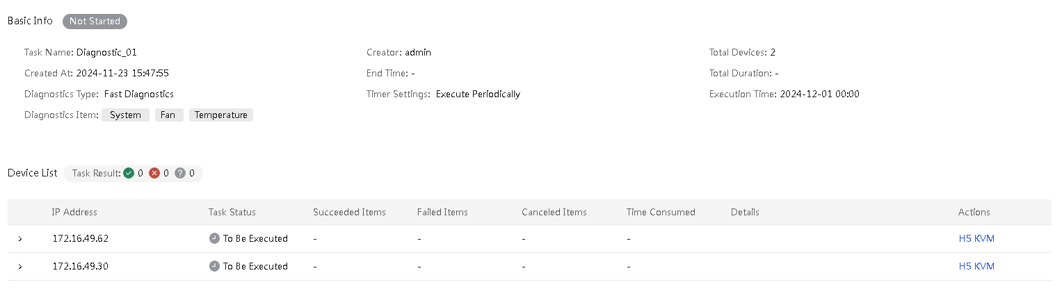
Parameters
· Basic information
¡ Task Name: Name of the task.
¡ Creator: Name of the user that created the task or edited the task most recently.
¡ Total Devices: Total number of servers included in the task.
¡ Created At: Time when the task was created or edited most recently.
¡ End Time: Time when the task was executed most recently.
¡ Total Duration: Total duration of the most recent task execution.
¡ Diagnosis Type: Select a server diagnosis type. Options include Fast Diagnosis and Stress Test.
¡ Scheduled Settings: Task execution mode.
¡ Execution Time: Time when the scheduled or periodic task was executed.
¡ Diagnosis Items
- If Fast Diagnosis is selected, the available items include System, BIOS, Processor, Memory, Storage, Network Adapter, GPU, PCIe, Power, Fan, and Temperature.
- If Stress Test is selected, the available items include Processor, Memory, and Storage.
· Device List
¡ Task Result
- ![]() : Number of the
devices on which the task has been executed successfully.
: Number of the
devices on which the task has been executed successfully.
- ![]() : Number of the
devices on which the task has failed.
: Number of the
devices on which the task has failed.
- ![]() : Number of the
devices in an unknown state.
: Number of the
devices in an unknown state.
¡ IP Address: IP address of a device.
¡ Task Status: Current task status on the device. Options include To Be Executed, In Progress, Succeeded, Failed, and Unknown.
¡ Succeeded Items: Number of the items that have been successfully diagnosed. You can hover over to display details.
¡ Failed Items: Number of the items that have failed to be diagnosed. You can hover over to display details.
¡ Canceled Items: Number of the items on which the diagnosis is canceled or unperformed. You can hover over to display details.
¡ Time Consumed: Time consumed by the most recent task execution.
¡ Details: Detailed information about the task.
- If the task has been executed successfully, you can download the report and view the information.
- If the task has failed, this field displays the cause for the failure.
Configure monitoring
Audit logs
UniSystem of the unified O&M version does not support this feature.
Event logs
Perform this task to display event logs generated by UniSystem or received from HDM for incorporated devices and to record user operation logs. This comprehensive log management method improves both the efficiency and security of log management processes. On the Event Logs page, you can view the details, such as time, event description of each log message, and remarks.
UniSystem can receive log messages forwarded by HDM only when syslog settings are correctly configured and the syslog service is enabled.
View audit logs
Procedure
1. In the navigation pane, select Menu > Monitor > Audit Logs.
The Event Logs page opens.
Figure 219 Event logs
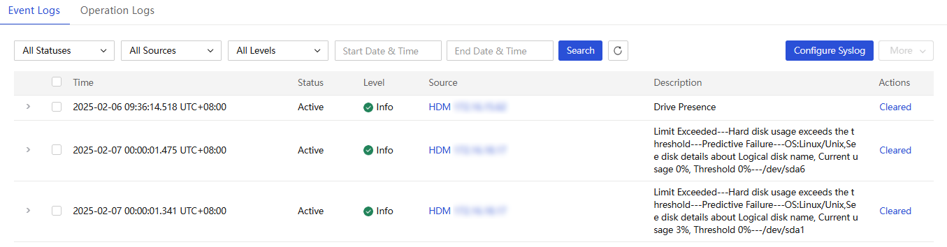
2. View a specified range of event logs.
a. Select the status, source, and severity to filter log messages.
b. Select the Start Date&Time and End Date&Time (optional).
c. Click Search. Log messages meeting the filtering criteria are displayed in the list below.
d. Click ![]() to clear the
filtering criteria and display all event log messages.
to clear the
filtering criteria and display all event log messages.
3. To clear an active event log message, click Cleared in the Actions column for the message. In the dialog box that opens, enter a description, and then click OK. To clear or restore multiple messages in bulk, select the messages, click More, and click the target option.The status of the log message becomes Cleared and an operation log message is generated.
4. To restore a cleared event log message, click Recover in the Actions column for the message. In the dialog box that opens, enter a description, and then click OK. To clear or restore multiple messages in bulk, select the messages, click More, and click the target option.The status of the log message becomes Active and an operation log message is generated.
5. To view the clearance or restoration log for
an event log message, click the chevron icon ![]() in the front of
the message.
in the front of
the message.
6. To view the device information, click the IP link in the Source column for the target log message.
Parameters
· Time: Time at which the event log was triggered.
· Status: Status of the event log. Options include Active and Cleared.
· Severity: Severity level of the event log. Options include Info, Minor, Major, and Critical.
· Source: Source of the event log. Options include HDM-IP and UniSystem.
· Description: Description of the event log.
Configure Syslog
With the Syslog function enabled, HDM sends Syslog logs to the UniSystem server for centralized management and unified storage of log data. You can query and analyze log information received from the HDM system in UniSystem to effectively monitor and manage the system operating status.
Procedure
1. In the navigation pane, select Menu > Monitor > Audit Logs.
The Event Logs page opens.
2. Click Configure Syslog. In the dialog box that opens, perform the following tasks:
a. Select whether to enable the syslog feature. By default, the feature is disabled.
b. Select the transmission protocol (UDP, TCP, or TLS).
c. Enter the port number for the protocol. The value range is 1 to 65535. The default port number for UDP and TCP is 514. The default port number for TLS is 6514.
d. If you select TLS, click the ![]() icon
in the CA Certificate, Server
Certificate, and Server Private Key fields
to upload the CA certificate, server certificate, and server private key,
respectively.
icon
in the CA Certificate, Server
Certificate, and Server Private Key fields
to upload the CA certificate, server certificate, and server private key,
respectively.
Figure 220 Configuring Syslog
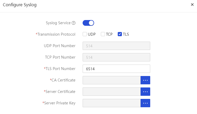
3. Click OK.
Operation logs
About this task
The system records the operation logs of the HDM system and the actions performed by users on the UniSystem Web interface. The operation log information includes the operation user, operation timestamp, and operation result. UniSystem can receive log messages forwarded by HDM only when syslog settings are correctly configured.
You can set filters to view only operation logs that match the filters.
Procedure
1. In the navigation pane, select Menu > Monitor > Audit logs.
2. Click the Operation Logs tab.
Figure 221 Operation Logs page
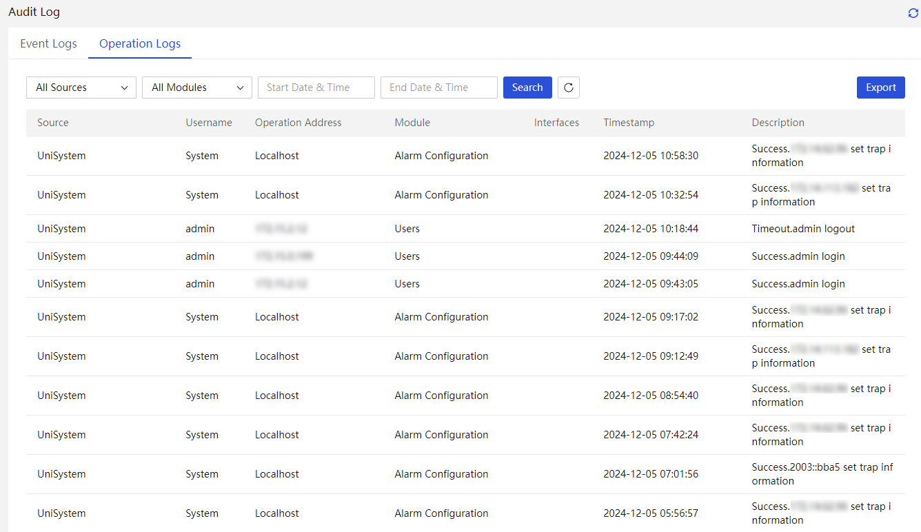
3. To filter log messages, select the alarm source, severity, and the start and end time (optional).
4. Click Search. This page displays only operation logs that match all the specified filter items.
5. To clear the search criteria and display all
logs, click ![]() .
.
6. Click Export to download all operation logs in CSV format to the device.
Configure listening settings
About this task
Perform this task to listen to and receive SNMP traps sent from the managed servers to help users monitor the server status.
UniSystem will apply the listening settings to all the managed servers so the servers will send SNMP traps to UniSystem. Then, UniSystem will record all the received SNMP traps on the Alarm Center page.
Restrictions and guidelines
· Make sure the listening IP address is on the same network segment as the HDM IP address of the managed server.
· The listening settings take effect on HDM of the managed server only if the HDM user has the administrator user role.
· After you enable the alarm voice feature, the voice will not be triggered again even if new alarms occur before the current alarm voice ends.
Procedure
1. Click ![]() or
or ![]() on the upper right corner of the page to view alarm record
information.
on the upper right corner of the page to view alarm record
information.
2. Click ![]() on the upper left
corner of the page, and perform the following steps:
on the upper left
corner of the page, and perform the following steps:
a. Enable the listening feature.
b. Select a listening IP address.
c. Set the listening port number.
d. Enable the alarm voice feature.
e. Select the alarm voice trigger level.
Figure 222 Configuring listening settings
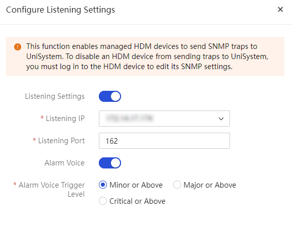
3. Click OK.
You can access the Alarm Center tab to view the received alarms.
You can view the specified IP addresses of the SNMP trap servers on the Configuration > Alarm Settings > SNMP trap page on HDM.
Parameters
· Listening Port: Port number for the local host to receive alarm notifications. The port number is in the range of 1 to 65535, and the default listening port is 162.
· Listening IP: IP address of the local host that receives alarm notifications from the server. For the UniSystem of the unified O&M version, enter the U-Center northbound virtual IP address used to receive the alarm notifications from the server.
· Alarm Voice: Enable or disable the alarm voice. This feature supports server alarms and infrastructure alarms, excluding alarms for CDU5204 templates.UniSystem triggers an alarm voice when it receives an alarm of the specified severity level. The alarm voice rings three times consecutively every time it is triggered, with a 5-second interval between each ring, taking about 12 seconds in total.
· Alarm Voice Trigger Level: Alarm severity levels that can trigger the alarm voice.
Alarm center
UniSystem of the unified O&M version does not support this feature.
Current alarms
About this task
The alarms page provides the following functions for you to view and manage the real-time server alarm information:
· Visualization: Display alarm information in charts and lists, helping you to better understand the operational status of the equipment.
· Real-time alarm displaying: Provide real-time viewing of various alarm information occurring on the server, assisting you in quickly responding to changes in device status.
· Alarm data export: Export the alarm information, making it convenient for you to generate reports and conduct analysis.
Procedure
1. In the navigation pane, select Menu > Monitor > Alarm Center > Current Alarms.
Figure 223 Current Alarms
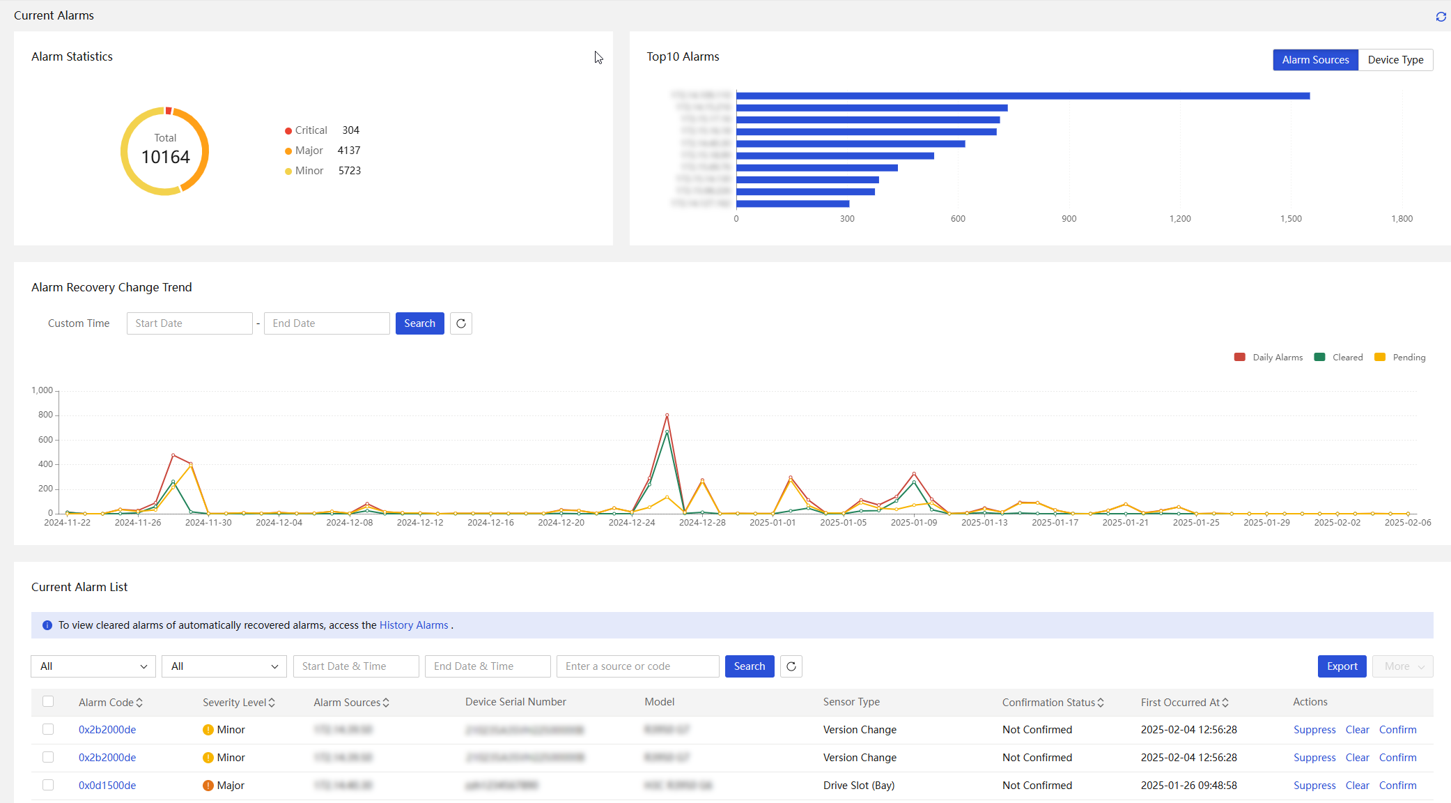
2. To view current alarm statistics:
¡ In the Alarm Statistics section, to view the number of alarms at the Critical, Major, and Minor levels.
¡ In the Top10 Alarms bar chart, to view the Top 10 alarms by source IP or device model. Click Alarm Sources or Device Types.
¡ In the Alarm Recovery Trend line chart, to display the trend in a specific period, set the start time and end time, and then click Search.
3. To view statistics of alarm list within a specified range:
¡ In the Current Alarm List section, to filter alarms, select the Severity Level and Sensor Type.
¡ Select the Start Date & Time and End Date & Time. The start time is the time of the first occurrence of the alarm.
¡ You can also specify an alarm source or alarm code to perform fuzzy matching.
¡ Click Search. Alarms meeting the filtering criteria are displayed in the list below.
¡ To
clear the filtering criteria and display all alarms, click ![]() .
.
4. To view detailed information about an alarm, click the alarm code.
5. To export alarms in the list, click Export.
6. In the Actions column of the alarm list, perform the following tasks as needed:
¡ To mask an alarm, click Suppress in the Actions column for the alarm.
¡ To clear an alarm, click Clear in the Actions column for the alarm and enter the clearing reason (optional). The cleared alarms will be displayed in the history alarm list.
¡ To confirm an alarm, click Confirm in the Actions column for the alarm and enter the clearing reason (optional).
¡ To cancel a confirmed alarm, click Cancel Confirmation in the Actions column.
7. To confirm, suppress, and clear alarms in bulk, select the alarms, click More, and click the target option.
Parameters
· Alarm Code: Primary code of the alarm.
· Severity: Severity level of the alarm, including Critical, Major, and Minor.
· Alarm Source: IP of the device on which the alarm was generated.
· Device Serial Number: Serial number of the device on which the alarm was generated.
· Model: Model of the device on which the alarm was generated.
· Sensor Type: Type of the status that generated the alarm.
· Confirmation Status: Confirmation status of the alarm, including Not Confirmed and Confirmed.
· First Occurred At: The time when the alarm first occurred.
History alarms
About this task
Perform this task to view history alarms that have been cleared or restored, cancel clearing, delete alarms, or export history alarms.
Procedure
1. Select Menu > Monitor > Alarm Center > History Alarms.
Figure 224 Histroy alarms
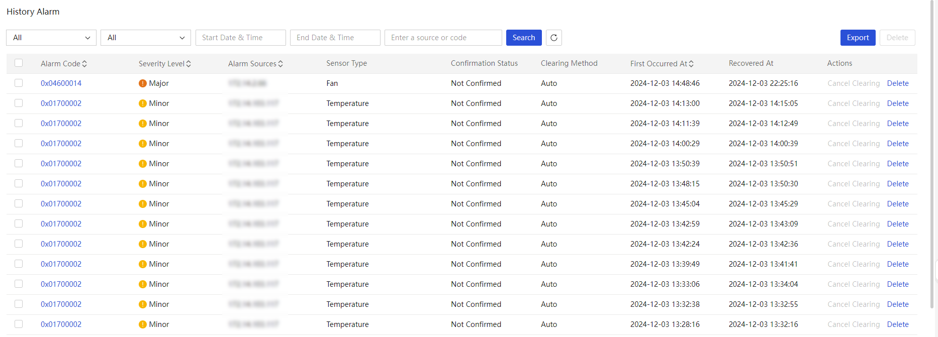
2. To view statistics of history alarm list within a specified range:
a. To filter alarms, select the Severity Level and Sensor Type.
b. Select the Start Date & Time and End Date & Time. The start time is the time of the first occurrence of the alarm.
c. (Optional.) Specify an alarm source or alarm code to perform fuzzy matching.
d. Click Search. Alarms meeting the filtering criteria are displayed in the list below.
e. To clear the filtering criteria and display
all alarms, click ![]() .
.
3. To view detailed information about an alarm, click the alarm code.
4. To export alarms in the list, click Export.
5. To delete alarms in the list, click Delete.
6. In the Actions column of the alarm list, perform the following tasks:
¡ To cancel the clearing of specific alarms, click Cancel Clearing in the Actions column for the alarm and enter the clearing reason (optional). The alarm will then be moved back to the current alarm list.
¡ To delete the history alarms, click Delete in the Actions column.
Events
About this task
Perform this task to view event alarms in normal state and delete or export event alarms.
Procedure
1. Select Menu > Monitor > Alarm Center > Events.
Figure 225 Events
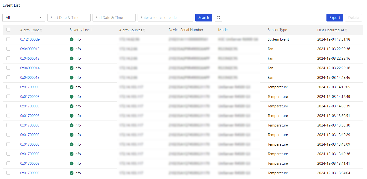
2. To view statistics of events within a specified range:
a. To filter events, select the Sensor Type.
b. Select the Start Date & Time and End Date & Time. The start time is the time of the first occurrence of the alarm.
c. (Optional.) Specify an alarm source or alarm code to perform fuzzy matching.
d. Click Search. Alarms meeting the filtering criteria are displayed in the list below.
e. To clear the filtering criteria and display
all alarms, click ![]() .
.
3. To view detailed information about an event, click the alarm code.
4. To export alarms in the list, click Export.
5. To delete alarms in bulk, select the target alarms, and then click Delete.
Suppressed alarms and events
About this task
Perform this task to view suppressed alarms and events, view detailed information, cancel suppression, and export suppressed alarms and events.
Procedure
1. Select Menu > Monitor > Alarm Center > Suppressed Alarms and Events.
Figure 226 Suppressed alarms and events

2. To view statistics of suppressed alarms and events within a specified range:
a. To filter events, select the Severity Level, and Sensor Type.
b. Select the Start Date & Time and End Date & Time. The start time is the time of the first occurrence of the alarm.
c. (Optional.) Specify an alarm source or alarm code to perform fuzzy matching.
d. Click Search. Alarms meeting the filtering criteria are displayed in the list below.
e. To clear the filtering criteria and display
all alarms, click ![]() .
.
3. To view detailed information about an alarm, click the alarm code.
4. To view the suppression rules, click the rule link.
5. To export alarms and events in the list, click Export.
6. To clear an alarm or event, click Delete in the Actions column for the alarm or event. To delete alarms in bulk, select the target alarms, and then click Delete.
7. To cancel suppression on an alarm, click Cancel Suppression and enter the reason (optional).
Alarm configuration
The alarm configuration section provides the following functions:
· Configure user notification settings.
· Configure notification policies to push specific alarms to users through third-party applications.
· Configure SNMP forwarding policies to forward specific alarm logs through SNMP.
|
|
NOTE: · To use this feature, you must add HDM server nodes to UniSystem first. For more information, see "Manage servers." · UniSystem of the unified O&M version does not support this feature. |
Alarm policies
Configure suppression policies
About this task
Perform this task to suppress the alarm generation for specific events to reduce interference and improve the efficiency of alarm management. You can view suppressed alarms and events in the suppressed alarm and event list.
Procedure
1. Select Menu > Monitor > Alarm Configuration > Alarm Policy.
2. Click the Suppression Policies tab.
Figure 227 Suppression policies

3. Click Add Policy and configure the policy as follows:
Figure 228 Add a suppression policy
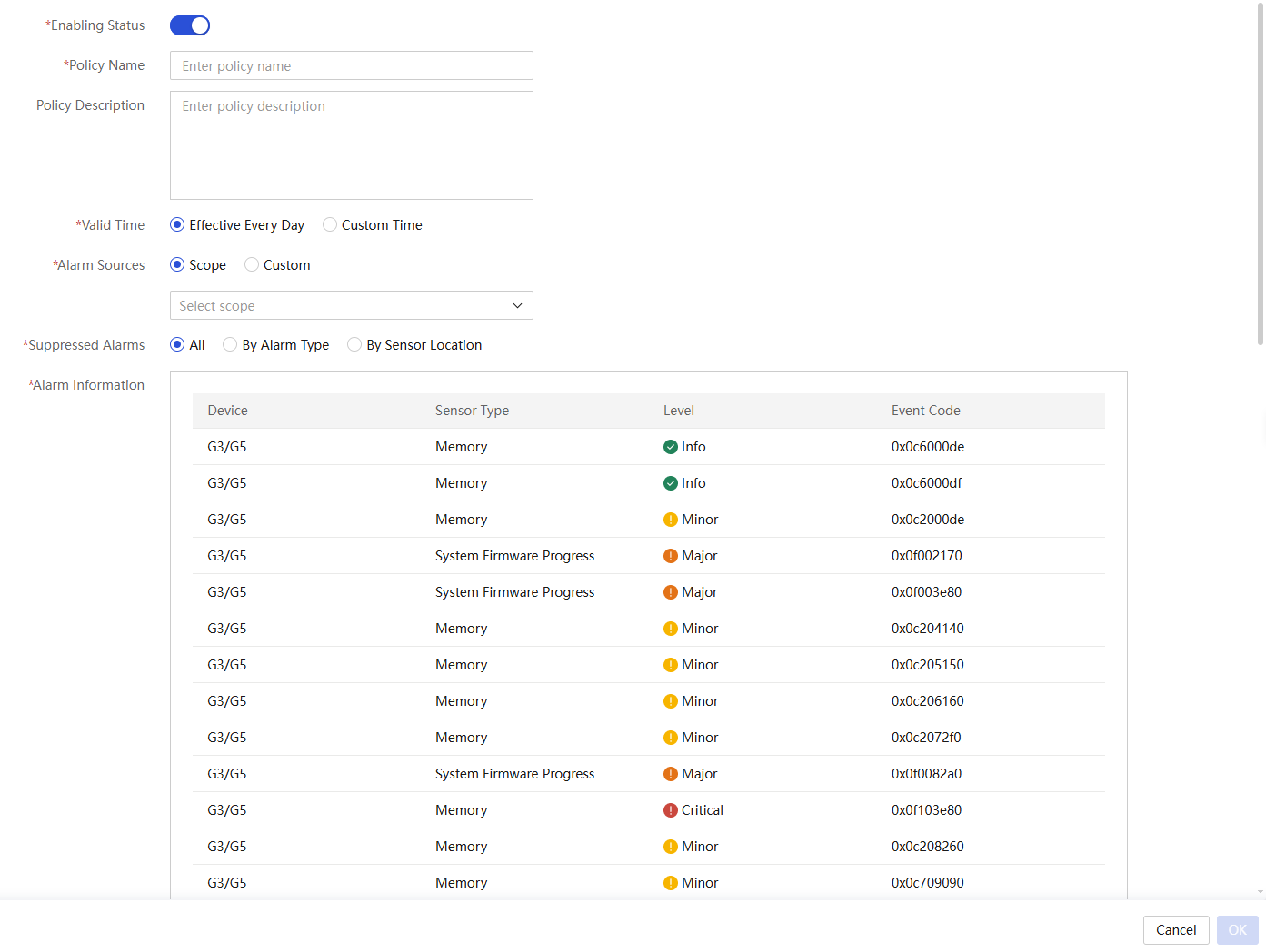
a. Enable this policy.
b. Enter the policy name and policy description.
c. Select the valid time.
d. Select the alarm sources.
e. Select the alarms to be suppressed. Options include:
- All: Suppress all alarms.
- By Alarm Type: If you select to suppress alarms by alarm type, click Add. In the dialog box that opens, select alarms and then click OK.
- By Sensor Location: If you select to suppress alarms by sensor location, select the target sensor locations as needed.
4. Click OK.
5. To edit, enable, disable, or delete a specific policy, click Edit, Enable, Disable, or Delete in the Actions column for the policy.
6. To delete, enable, or disable policies in bulk, select the target policies, and then click Policy Management.
Parameters
· Policy Name: Name of the alarm suppression policy.
· Description: Description of the alarm suppression policy.
· Valid Time: Time during which the suppression policy takes effect. The suppression policy suppresses alarms only during a specific time period.
· Alarm Sources: Sources of the alarms to be suppressed. Options include:
¡ Scope: Suppress alarms for all servers in the scope.
¡ Custom: Suppress alarms for the specified servers.
· Suppressed Alarms: Select alarms to be suppressed.
· Alarm Information: Range of alarms to be suppressed.
Configure compression policies
About this task
Perform this task to aggregate all alarms of the same type from managed servers into a single alarm and notify at a fixed interval.
Procedure
1. Select Menu > Monitor > Alarm Configuration > Alarm Policy.
2. Click the Compression Policy tab.
Figure 229 Compression policy
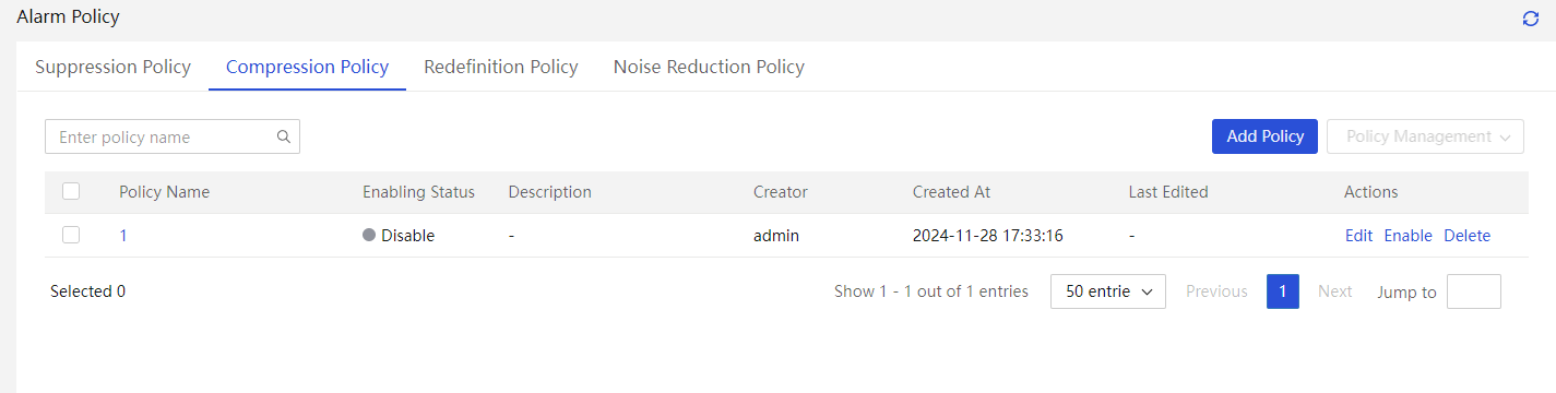
3. Click Add Policy and configure the compression policy as follows:
Figure 230 Add a compression policy
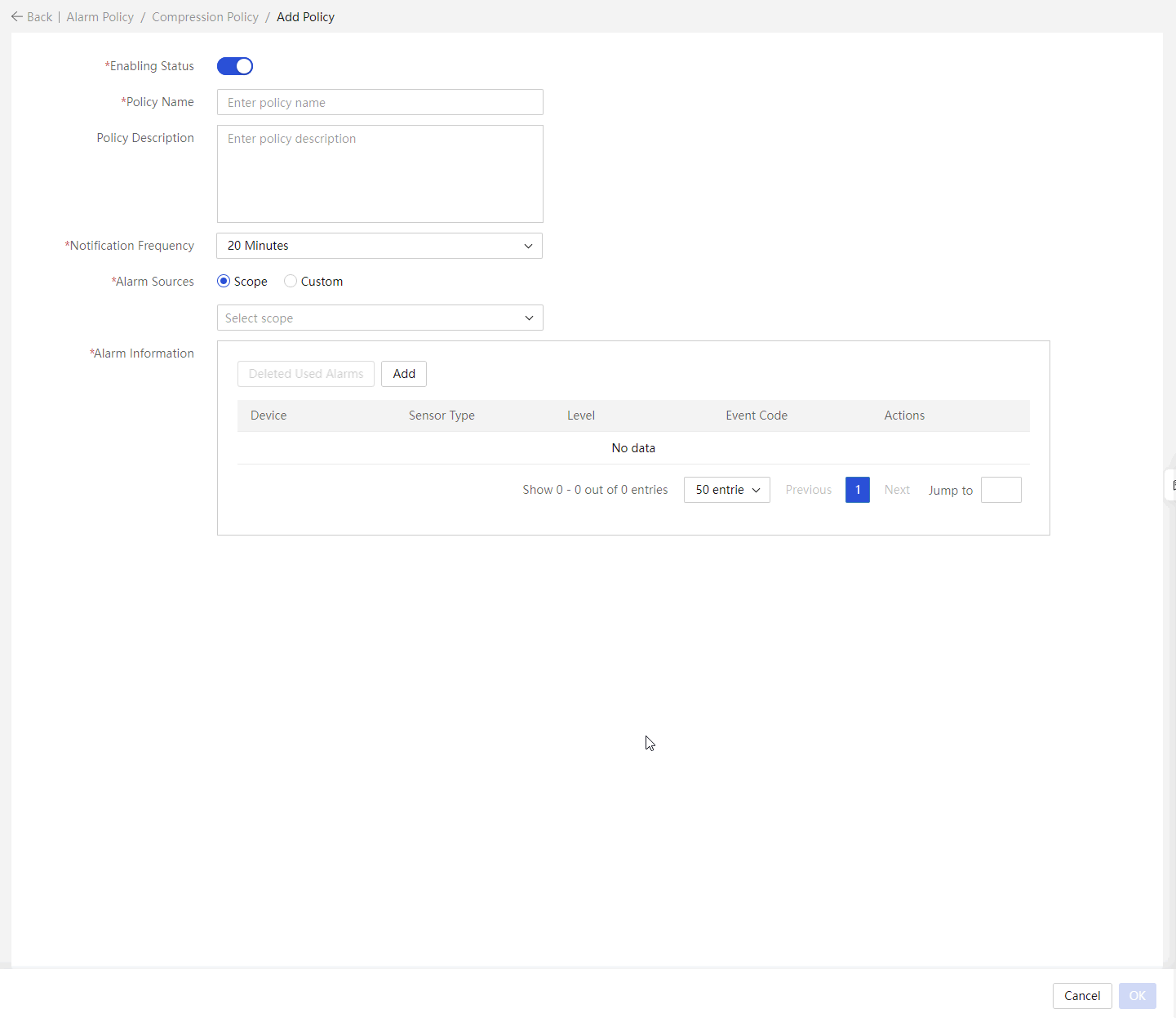
a. Enable this policy.
b. Enter the policy name and policy description.
c. Select the notification frequency.
d. Select the alarm sources. You can select Scope to compress the alarms for all servers in the scope or select Custom to compress alarms for specific servers.
e. Click Add and select the alarms to be compressed.
- On the G3/G5 Devices tab, select alarm information for G3/G5 devices, and then click OK.
- On the G6/G7 Devices tab, select alarm information for G6/G7 devices, and then click OK.
You can filter the alarm logs by alarm severity, sensor type, and keyword.
4. To delete alarms compressed by another policy, click Deleted Used Alarms.
5. Click OK.
6. To edit, enable, disable, or delete a specific policy, click Edit, Enable, Disable, or Delete in the Actions column for the policy.
7. To delete, enable, or disable policies in bulk, select the target policies, and then click Policy Management.
Parameters
· Policy Name: Name of the alarm compression policy.
· Description: Description of the alarm compression policy.
· Notification Frequency: Specify the notification frequency. UniSystem notifies alarms matching the policy once based on the specified frequency to compress alarms. For example, if the frequency is 20 minutes, starting from the time the policy is enabled, UniSystem compresses matching alarms received during every 20 minutes as one and send the alarm at the end of the 20-minute cycle.
· Alarm Sources: Sources of the alarms to be compressed. Options include:
¡ Scope: Compress alarms for servers in the scope.
¡ Custom: Compress alarms for the specified servers.
· Alarm Information: Range of alarms to be compressed. Alarms not in the list are forwarded and recorded as configured.
Configure redefinition policies
About this task
Perform this task to redefine the severity level of alarm logs matching a policy.
Procedure
1. Select Menu > Monitor > Alarm Configuration > Alarm Policy.
2. Click the Redefinition Policy tab.
Figure 231 Redefinition policy
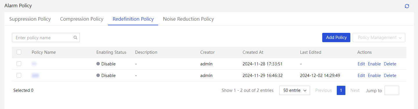
3. Click Add Policy and configure the policy as follows:
Figure 232 Add a redefinition policy

a. Enable this policy.
b. Enter the policy name and policy description.
c. Select the alarm sources. You can select Scope to redefine alarms for all servers in the scope or select Custom to redefine alarms for specific servers.
d. Click Add and select the alarms to be redefined.
- On the G3/G5 Devices tab, select alarm information for G3/G5 devices, and then click OK.
- On the G6/G7 Devices tab, select alarm information for G6/G7 devices, and then click OK.
You can filter the alarm logs by alarm severity, sensor type, and keyword.
4. Select the redefined severity level.
5. To delete alarms redefined by another policy, click Deleted Used Alarms.
6. Click OK.
7. To edit, enable, disable, or delete a specific policy, click Edit, Enable, Disable, or Delete in the Actions column for the policy.
8. To delete, enable, or disable policies in bulk, select the target policies, and then click Policy Management.
Parameters
· Policy Name: Name of the alarm redefinition policy.
· Description: Description of the alarm redefinition policy.
· Alarm Sources: Sources of the alarms to be redefined. Options include:
¡ Scope: Redefine alarms for servers in the scope.
¡ Custom: Redefine alarms for the specified servers.
· Redefined Severity: Select the redefined severity level for alarms matching the policy.
· Alarm Information: Range of alarms to be redefined.
Configure the noise reduction policy
About this feature
With a noise reduction policy configured, UniSystem will forward an alarm message to the alarm center only after the number of triggers for the alarm reaches the noise reduction threshold.
Restrictions and guidelines
Only enabled noise reduction policies can affect alarm forwarding. UniSystem will forward an alarm message only after the number of triggers for the alarm reaches the noise reduction threshold, thus reducing number of alarm notifications.
Procedure
1. In the navigation pane, select Menu > Monitor > Alarm Configuration > Alarm Policy.
2. Click the Noise Reduction Policy tab.
Figure 233 Noise reduction policy
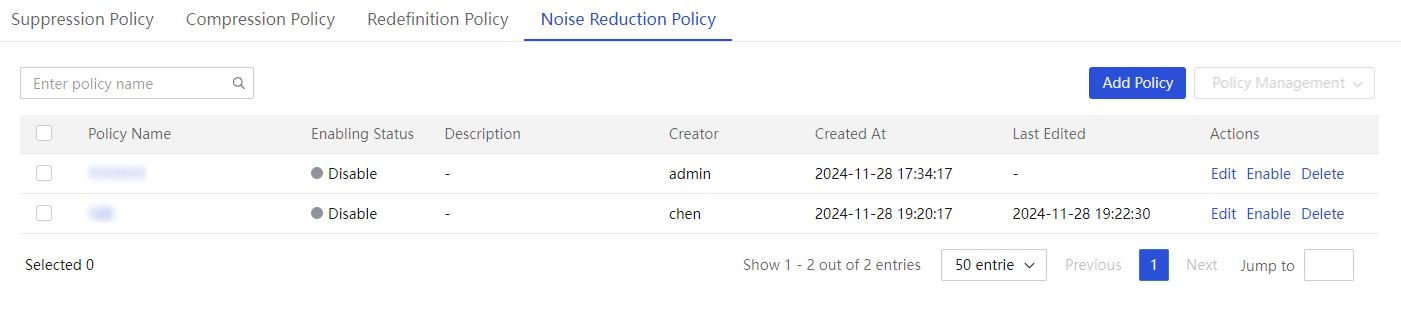
3. Click Add Policy and configure the policy as follows:

a. Enable this policy.
b. Enter the policy name and policy description.
c. Enter the noise reduction threshold.
d. Select the alarm source. Options include:
- Scope: Perform noise redunction on all servers in the specified scopes. You can select multiple scopes.
- Custom: Perform noise redunction on the specified servers. You can select multiple servers.
e. Click Add. Select the alarm information.
- On the G3/G5 Devices tab, select alarm information for G3/G5 devices, and then click OK.
- On the G6/G7 Devices tab, select alarm information for G6/G7 devices, and then click OK.
Alarm logs support filtering by alarm severity level, sensor type, and input keywords, allowing quick location of corresponding information.
4. To delete alarms selected by another noise reduction policy, click Deleted Used Alarms.
5. Click OK.
6. To edit, enable, disable, or delete a specific policy, click Edit, Enable, Disable, or Delete in the Actions column for the policy.
7. To enable, disable, or delete multiple policies, select the policies, and then click Enable Selected, Disable Selected, or Delete Selected.
Parameters
· Policy Name: Name of the UniSystem alarm noise reduction policy.
· Policy Description: Description of the UniSystem alarm noise reduction policy.
· Noise Reduction Threshold: Number of triggers for an alarm log that must be reached before UniSystem sends the alarm log. For example, if you set the noise reduction threshold to 5, UniSystem will forward an alarm log only after the log has been triggered 5 times.
· Alarm Source: Select the devices that require alarm noise reduction. Options include:
¡ Scope: Perform noise redunction on all servers in the specified scopes. You can select multiple scopes.
¡ Custom: Perform noise redunction on the specified servers. You can select multiple servers.
· Alarm Information: Range of alarms on which the noise reduction policy takes effect.
Configure user notification
UniSystem of the unified O&M version does not support this feature.
About this task
Perform this task to add the email addresses and phone numbers of contacts to receive notifications.
Procedure
1. In the navigation pane, select Menu > Monitor > User Notification Configuration.
Figure 235 User Notification Configuration page
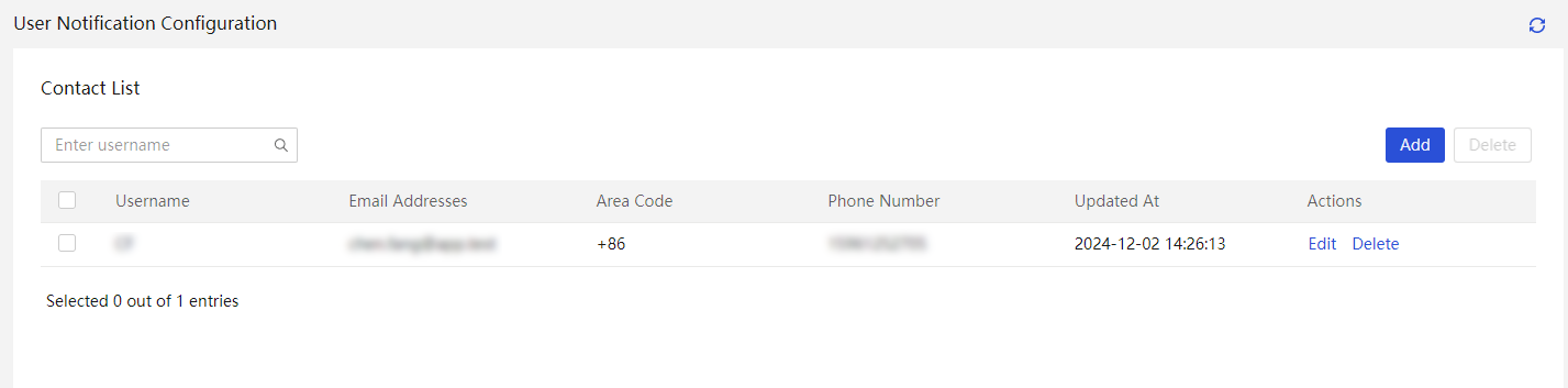
2. Click Add and add a contact as follows:
Figure 236 Add contact
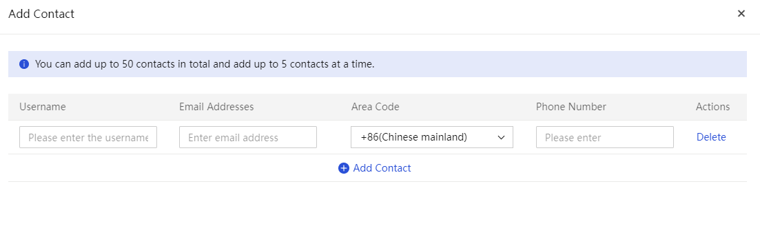
a. Enter a username.
b. Enter an email address.
c. Enter an area code.
d. Enter a phone number.
3. Click OK.
4. To delete a contact, click Delete in the Actions column for that contact. To edit a contact, click Edit in the Actions column for that contact.
5. To bulk delete contacts, select the target contacts and click Delete in the upper right corner of the page.
Configure notification policies
UniSystem of the unified O&M version does not support this feature.
About this task
Perform this task to configure notification policies, based on which UniSystem forwards matching alarms to the corresponding contacts or contact groups in time.
Before configuring a notification policy, complete notification method settings first. For more information, see "System interfacing."
Procedure
1. In the navigation pane, select Menu > Monitor > Alarm Configuration > Notification Policy.
Figure 237 Notification Policy page

2. Click Notification Template Configuration and configure the template as follows:
Figure 238 Notification template configuration
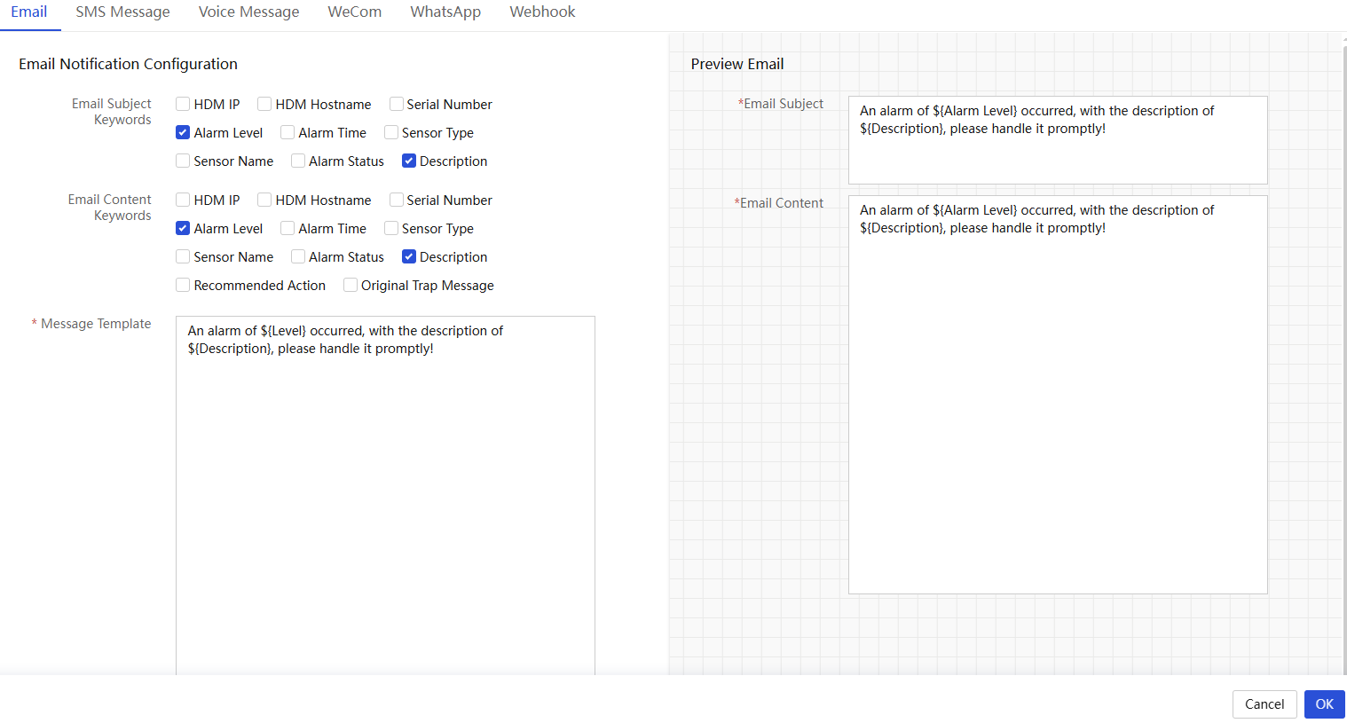
a. Select the notification subject and content keywords. You can customize the notifications for email, WeCom, SMS, voice message, WhatsApp, and Webhook.
b. (Optional) Edit the message template.
c. Click OK.
3. Click Add Policy and configure the policy as follows:
Figure 239 Add policy
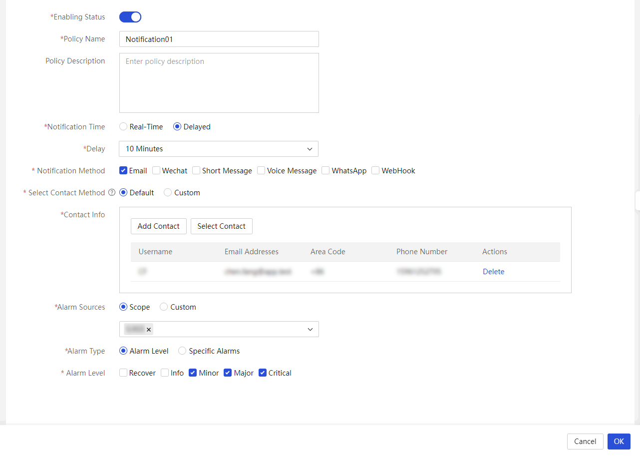
a. Enable the notification policy.
b. Enter the policy name and description.
c. Select the notification time.
d. Select one or more notification methods. Options include Email, WeCom, SMS Message, Voice Message, WhatsApp, and Webhook.
e. Add a new contact.
- Click Add Contact. The new contact will be synchronized to the user notification configuration.
- To select contacts from the user notification configuration, click Select Contact.
If you select to customize the contact methods, you must configure contacts separately for each notification method.
f. Select Alarm Source. Options include:
- Scope: Select alarms for all servers in the specified scopes. You can select multiple scopes.
- Custom: Select alarms for the specified servers. You can select multiple servers.
g. Select Alarm Type. Options include:
- Alarm Level: Notify based on alarm levels. You can select multiple levels.
- Specific Alarms: Notify based on the alarm message. You can select multiple alarm messages. To clear alarm messages selected by another policy, click Deleted Used Alarms.
h. Click OK.
4. To edit, enable, disable, or delete a notification policy, click Edit, Enable, Disable, or Delete in the Actions column for that notification policy.
5. To delete, enable, or disable notification policies in bulk, select the target notification policies, click Policy Management.
Parameters
· Email Subject: Supported variables include:
¡ ${IP}: HDM IP address of the server.
¡ ${HDM_HostName}: HDM host name.
¡ ${SN}: Server serial number.
¡ ${Level}: Alarm severity level.
¡ ${Time}: Alarm generation time.
¡ ${SensorType}: Sensor type.
¡ ${SensorName}: Sensor name.
¡ ${AlertStatus}: Alarm status, including triggered and cleared.
¡ ${Description}: Alarm description.
· Content keywords: Supported variables include:
¡ ${IP}: IP address of HDM for the server.
¡ ${HDM_HostName}: HDM hostname.
¡ ${SN}: Server serial number.
¡ ${Level}: Severity level.
¡ ${Time}: Time when an alarm occurs.
¡ ${SensorType}: Sensor type.
¡ ${SensorName}: Sensor name.
¡ ${AlertStatus}: Alarm status. Option includes triggered and cleared.
¡ ${Description}: Alarm description.
¡ ${RecommendedAction}: Recommended action.
¡ ${TrapMessage}: Original trap message.
· Notification Method: Select a third-party application to forward notifications.
· Real-Time: Allow UniSystem to send notifications immediately upon receiving alarm messages.
· Delayed: Allow UniSystem to send notifications after a delayed period. If the alarm is cleared within the delay, UniSystem does not send a notification. If the alarm still exists after the delay, UniSystem sends a notification.
· Alarm Sources: Source servers for notification. Options include:
¡ Scope: Select alarms for all servers in the specified scopes. You can select multiple scopes.
¡ Custom: Select alarms for the specified servers. You can select multiple servers.
· Alarm Type: Select an alarm notification type. Options include:
¡ Alarm Level: Notify based on alarm levels.
¡ Specific Alarms: Notify based on the alarm message.
Restrictions and guidelines
· In either of the following scenarios, the configured notification recipients can receive notifications after the server generates an alarm:
¡ When the listening feature is enabled, the severity level of the alarm is equal to the specified level in the policy, or the message of the alarm is consistent with an alarm specified in the policy.
¡ When the listening feature is disabled, the health state of the server changes, and the corresponding server email notification method has been configured in the notification policy.
· If the alarm notification severity has been set in HDM, UniSystem performs notification filtering based on the alarm messages filtered by HDM.
SNMP forwarding policies
UniSystem of the unified O&M version does not support this feature.
About this task
Perform this task to add SNMP users and target hosts to receive SNMP traps (trap destinations) from the managed servers.
UniSystem will receive SNMP traps that have a severity level equal to or higher than the specified level from the managed servers, and then forward the traps to the target trap hosts.
Procedure
1. In the navigation pane, select Menu > Monitor > Alarm Configuration > SNMP Forwarding Policy.
Figure 240 Policy list

2. Click Add. In the dialog box that opens, configure the policy parameters as needed.
a. Enable the policy.
b. Enter the policy name and specify the destination IP address and destination port.
c. Select an SNMP version.
- If you select v1 and v2c, enter the community string.
- If you select v3, enter the username of an SNMP user, select a security level, and then enter user information for authentication based on the security level.
d. Select severity levels of SNMP traps to be forwarded.
3. Click OK.
4. To test an SNMP forwarding policy, click Test in the Actions column for that SNMP forwarding policy.
5. (Optional.) To edit, enable, disable, or delete an SNMP forwarding policy, click Edit, Enable, Disable, or Delete in the Actions column for that SNMP forwarding policy.
6. (Optional.) To delete, enable, or disable forwarding policies in bulk, select the target forwarding policies, click Policy Management.
Parameters
· Username: Name of an SNMP user.
· Destination IP: IP address of the target host to receive SNMP traps.
· Destination Port: Port number of the target host to receive SNMP traps.
· Version: Version of SNMP traps to be forwarded, v1, v2c, or v3.
· Community: Trap community string for authentication. This field is required if version v1 or v2c is selected.
· Username: Name of an SNMP user. This field is required if version v3 is selected.
· Security Level: Security level of the SNMP user, including None, Authentication, and Authentication and Privacy.
· Authentication Protocol: Protocol used to authenticate the user, including MD5 and SHA.
· Authentication Password: Password to authenticate the user.
· Privacy Protocol: Protocol used to protect the privacy of the user, including DES and AES128.
· Privacy Password: Privacy password of the user.
· Output Trap Level: Severity levels of SNMP traps to be forwarded, including Info, Minor, Major, and Critical.
Fault prediction
|
|
NOTE: · This feature is available only on G6 and later servers and requires servers to have a server software license installed. · UniSystem of the unified O&M version does not support this feature. · Drive prediction supports only SATA HDDs. |
Drive prediction
Drive faults occur frequently in data centers due to the large number of drives, the extensive amount of data storage, and the short lifecycle of the drives. Drives have a high fault rate compared to other server components. UniSystem examines the S.M.A.R.T. data from drives, utilizing data analysis and feature extraction to forecast potential drive faults and present the results. You can stay informed about drive risks. This feature helps you to prevent drive faults from disrupting normal operations.
Procedure
1. In the navigation pane, select Menu > Fault Prediction > Drive Prediction.
2. Enable drive prediction feature.
3. View drive prediction result statistics.
Figure 241 Viewing drive prediction result statistics
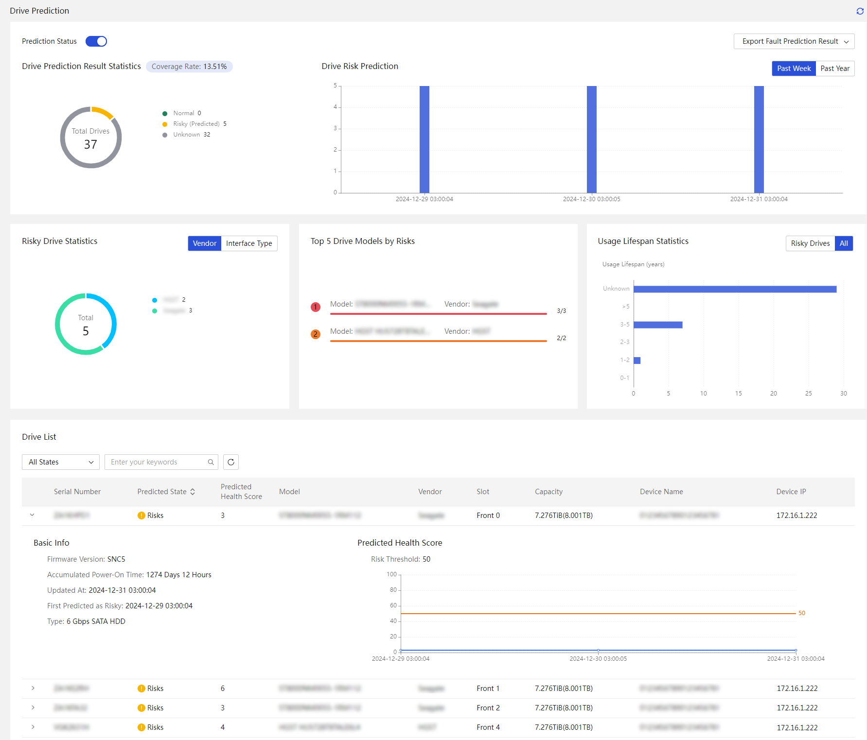
4. (Optional) Export the prediction result.
5. Click Export Fault Prediction Result. Select All Drives, Normal Drives, Risky (Predicted) Drives, or Unknown Drives to export information about the target drive type.
Description
· Drive Prediction Result Statistics: Displays the numbers of normal drives, risky (predicted) drives, and unknown drives and the drive population by predicted state.
¡ Normal: Drives without potential risks.
¡ Risky (Predicted): Drives with potential risks.
¡ Unknown: Drives with unpredictable health status. Possible reasons include:
- The server does not support this feature. The server model is earlier than G6.
- The server is not installed with a license.
- The drive is not an SATA HDD.
- The system fails to obtain drive data for 7 continuous days.
· Drive Risk Prediction: Displays the number of risky drives for each time period in the past week or year. You can hover over a bar to view the risk drive information in the specific period.
¡ Serial Number: Serial number of the drive.
¡ Vendor: Manufacturer of the drive.
¡ Model: Drive model.
¡ First Predicted as Risky: Time at which the drive was first predicted to have a potential risk.
¡ Presence: Presence status of the drive.
· Risky Drive Statistics: Displays the current number of predicted risky drives. The statistics is displayed by manufacturer or interface type.
· Top 5 Drive Models by Risks: Displays the Top5 drive models with the most risks and their manufacturers.
· Usage Lifespan Statistics: Displays statistics on the lifespan of risky drives or all drives.
· Drive List: Displays information about all drives managed by UniSystem. You
can set the number of entries displayed per page, filter drives, and search for
the target drives. To view basic drive information and a line chart of health
statistics for the past week, click the chevron icon ![]() at the
front of the serial number.
at the
front of the serial number.
¡ Serial Number: Serial number of the drive.
¡ Predicted State: Predicted state of the drive.
¡ Predicted Health Score: Predicted health score of the drive.
¡ Vendor: Manufacturer of the drive.
¡ Model: Drive model.
¡ Slot: Slot where the drive resides.
¡ Capacity: Capacity of the drive.
¡ Device Name: Name of the device on which the drive resides.
¡ Device IP: IP address of the device on which the drive resides.
¡ Firmware Version: Firmware version of the drive.
¡ Accumulated Power-On Time: Accumulated power-on time of the drive.
¡ Updated At: Time at which the drive prediction was updated.
¡ First Predicted as Risky: Time at which the drive was first predicted to have a potential risk.
¡ Type: Data transfer speed and interface type of the drive.
¡ Predicted Health Score: Line chart of drive health scores for the past week and the risk threshold.
Manage energy efficiency and prediction (G6 and later servers)
Only UniSystem of the virtual machine version supports this feature.
Energy efficiency statistics
About efficiency statistics
Users can use this feature to view the daily and monthly power consumption, power usage, U-space usage statistics, power consumption statistics, Top 5 power consumers, and Top 5 U-space occupancy in data center, equipment room, and rack views. Additionally, they can see power consumption predictions for individual racks, the entire equipment room, and the entire data center through intelligent prediction algorithms.
Power consumption prediction is performed based on history data. If specific actions are performed on devices within a data center after a prediction is generated, the actual power consumption might differ a lot from the predicted power consumption, or the system might fail to obtain the predicted power consumption for a specific period. This does not affect device operation.
|
|
IMPORTANT: You can view the power consumption prediction data only when both the following conditions are met: · The number of days of historical power consumption data obtained by UniSystem is greater than or equal to 7 days. · The amount of historical power consumption data obtained by UniSystem is greater than or equal to 70% of the theoretical value of the total data amount during this time period. |
Procedure
1. In the navigation pane, select Menu > Energy and Prediction > Energy Efficiency Statistics.
2. Select the target view from the navigation pane.
3. (Optional.) Select whether to enable power consumption forecast.
4. (Optional.) Specify the start and end time, and then click Search.
Figure 242 Enabling energy efficiency statistics collection
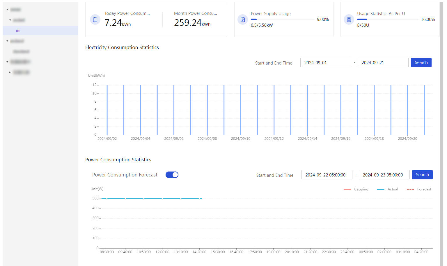
Energy efficiency analysis
This module allows you to identify low-load or idle servers and transfer extra services to these servers or power off these servers to optimize the power consumption of the entire data center. This module supports detection only on NVIDIA GPUs. You must install NVIDIA GPU drivers in advance.
This feature is available only when UniSystem runs on a VM.
Configure inlet temperature analysis
Perform this task to view server temperature summary information, identify servers with temperature anomalies, and power on or power off servers in batch.
View inlet temperature information
1. In the navigation pane, select Menu > Energy and Prediction > Energy Efficiency Analysis > Inlet Temperature Analysis.
2. View inlet temperature information for servers.
Figure 243 Inlet temperature analysis
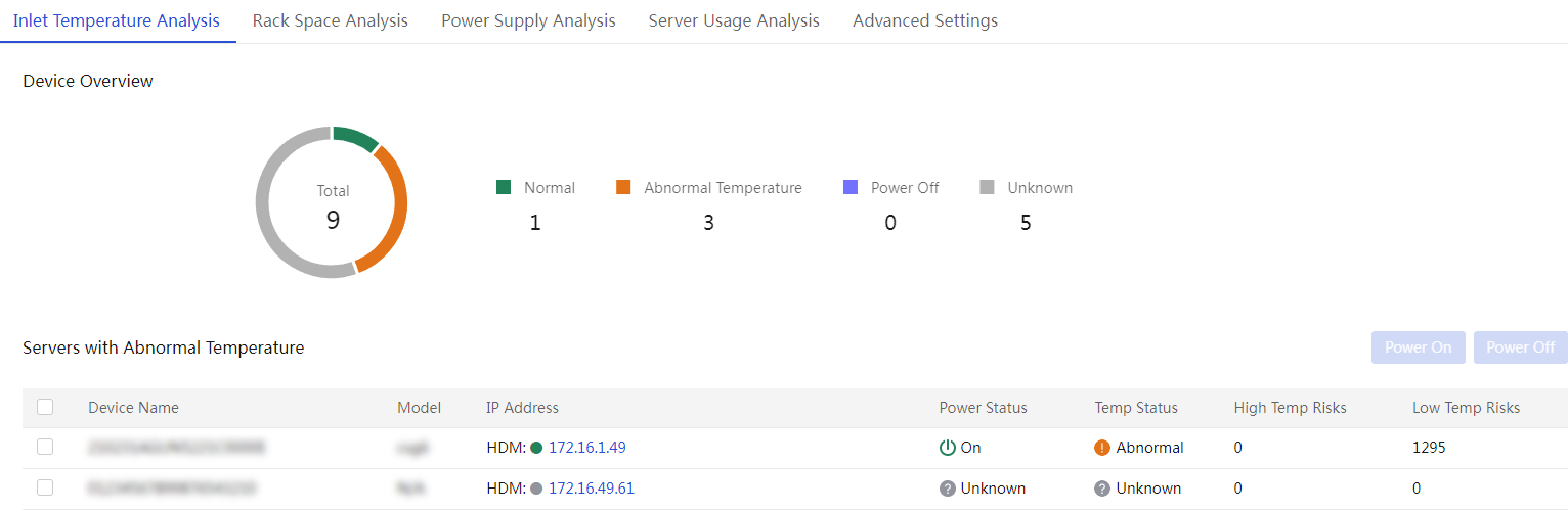
Power on servers in batch
1. Select servers from the Servers with Abnormal Temperature list.
2. Click Power On. In the dialog box that opens, confirm devices to be powered on, agree to the operation consequence notice, and click OK.
Figure 244 Powering on servers in batch
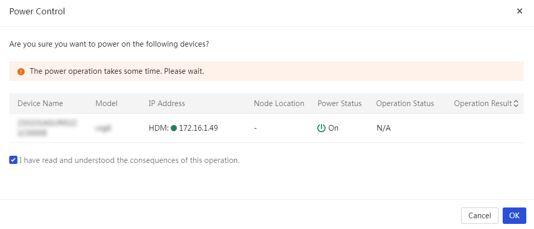
Power off servers in batch
1. Select servers from the Servers with Abnormal Temperature list.
2. Click Power Off. In the dialog box that opens, confirm devices to be powered off, agree to the operation consequence notice, and click OK.
Figure 245 Powering off servers in batch
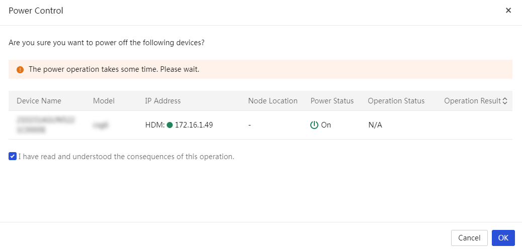
Configure server usage analysis
Perform this task to view server summary information, abnormally loaded servers, and server distribution by load status. You can power on and power off abnormally loaded servers in batch, configure power capping, and view server load trend in the past day.
View server usage information
1. In the navigation pane, select Menu > Energy and Prediction > Energy Efficiency Analysis > Server Usage Analysis.
2. View server usage information.
Figure 246 Server usage analysis
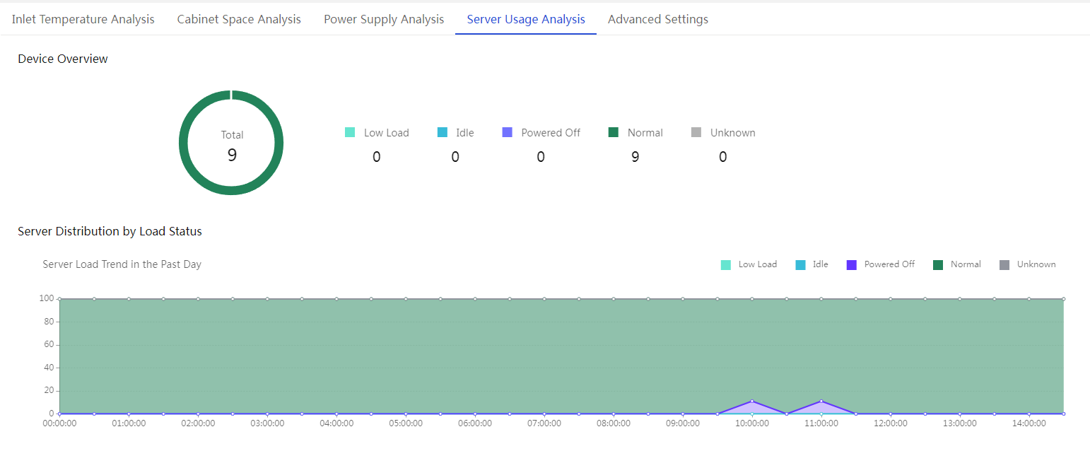
Power on servers in batch
1. Select servers from the abnormally loaded server list.
2. Click Power On. In the dialog box than opens, confirm devices to be powered on, agree to the operation consequence notice, and click OK.
Power off servers in batch
1. Select servers from the abnormally loaded server list.
2. Click Power Off. In the dialog box than opens, confirm devices to be powered off, agree to the operation consequence notice, and click OK.
Configure power cap settings
1. Select a server from the abnormally loaded server list.
2. Click Power Cap Settings for the server. View and configure power capping parameters.
3. Click OK.
Rack space analysis
This module allows you to view rack space usage information.
Procedure
1. In the navigation pane, select Menu > Energy and Prediction > Energy Efficiency Analysis.
2. View rack space analysis information.
Figure 247 Viewing rack space analysis
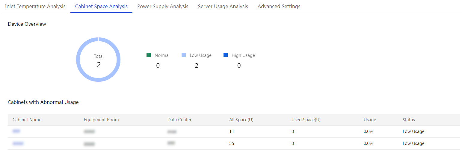
Power supply analysis
This module allows you to view rack power supply information.
Procedure
1. In the navigation pane, select Menu > Energy and Prediction > Energy Efficiency Analysis.
2. Click the Power Supply Analysis tab.
3. View rack space analysis information.
Figure 248 Analyzing power supply
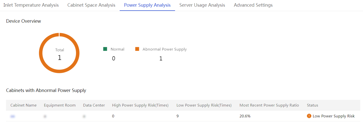
Configure advanced settings
This feature is used to configure parameter settings for inlet temperature analysis, rack space analysis, power supply analysis, and server usage analysis.
Procedure
1. In the navigation pane, select Menu > Energy and Prediction > Energy Efficiency Analysis > Advanced Settings.
2. Enable inlet temperature analysis. Select ASHRAE or Custom for Set Temp Range. If you select ASHRAE, specify a type (A1, A2, A3, or A4) and configure the High Temp Count Limit, Low Temp Count Limit, and Duration. If you select Custom, configure parameters such as the temperature range.
3. Enable rack space analysis, and specify the usage range.
4. Enable power supply analysis, and specify the power supply ratio range, high supply upper limit, lower supply upper limit, and duration.
5. Enable server usage analysis. Select CPU, GPU, and Memory for Set Thresholds as needed and specify respective values in the CPU Usage Lower Limit (%), GPU Usage Lower Limit (%), Memory Usage Lower Limit (%), and Duration (day) fields for idle and low-load servers.
6. Click Save.
Figure 249 Configuring advanced settings
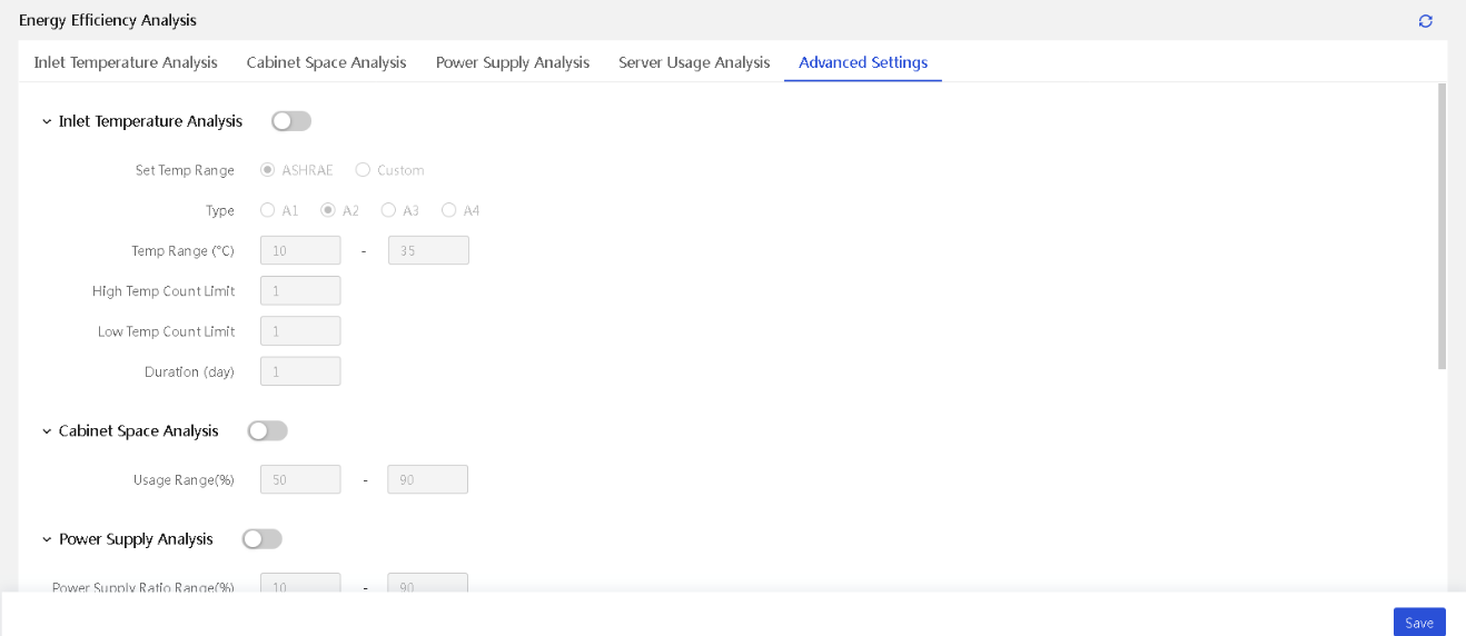
Perform one-key power consumption limit
About this task
When the power supply system in the equipment room fails, the emergency power supply will be enabled. To prolong the operation time with the emergency power supply, you can use this feature to limit the power consumption of servers to a low level. The configuration might affect server performance or shut down the server unexpectedly.
Restrictions and guidelines
· When you configure the power consumption policy and the minimum power consumption of the current device is lower than 150 W, the system sets the cap value to 150 W by default.
· If the power state is off or HDM is abnormal, the power consumption policy cannot be issued.
Procedure
1. In the navigation pane, select Menu > Energy and Prediction > One-Key Power Consumption Limit. The page displays the information about G6/G7 servers managed by the data center.
Figure 250 One-Key Power Consumption Limit page

2. To filter server information, specify the data center, equipment room, cabinet, and device name. Fuzzy matching is supported.
3. Click Policy Configuration to select the server to be configured.
Figure 251 Selecting a policy editing method
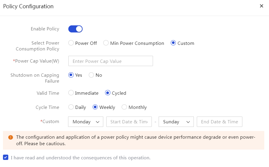
4. Click Apply Policy. In the dialog box that opens, enter YES to confirm the operation and then click OK.
5. Select power consumption policy, options include: Power Off, Min Power Consumption, and Custom.
¡ Power Off: The server shuts down.
¡ Min Power Consumption: The power cap is set to the minimum power consumption.
¡ Custom: Customize the power consumption strategy.
6. If you select the Custom, set the power cap value.
¡ Customize the server power cap, with an effective range of 150 to 10,000W.
¡ Select whether to enable the shutdown feature if the power cap is exceeded.
¡ Set the activation time, options include Immediate and Cycled.
7. Select the agreement check box, which indicates that you understand the possible consequences of your configuration.
8. Click OK.
Descpiption
· Device Name: Name of the server.
· Model: Model of the server.
· Device IP: HDM IP address used to connect to UniSystem.
· Data Cener: Data center to which the server belongs.
· Equipment Room: Equipment room where the server resides.
· Cabinet: Cabinet where the server resides.
· Power Status: Power status of the server, including ![]() ,
, ![]() , and
, and ![]() , which
represents Off, On, and
Unknown, respectively.
, which
represents Off, On, and
Unknown, respectively.
· Current Power (W): Current power of the server.
· Min Power (W): Minimum power of the server in a day.
· Power Consumption Limit Policy: Options include:
¡ Off.
¡ Power Off: Power off the server.
¡ Min Power Consumption: The power cap value is the minimum power consumption of the server.
¡ Custom: In custom mode, you must specify the following parameters:
- Power Cap Value (W): Power cap value in the range of 150 to 10000 W.
- Shutdown on Capping Failure: If the server power exceeds the power cap and does not drop below it within 30 seconds, power capping fails. If Yes is selected, the server will forcibly shut down. If No is selected, the server will continue running.
- Valid Time: Execution method of the power consumption policy. Options include Immediate and Cycled.
- Cycle Time: Cycle time if the effective time is Cycled.
Cabinet intelligent power management
About cabinet intelligent power management
This module can adjust power cap values of all G6 devices in the specified cabinet dynamically. The system uses the history power statistics of G6 devices to predict the device power consumption in next 30 minutes every 30 minutes, and sets a power cap every 5 minutes. Then, the system determines the power cap value for each G6 device and adjust the value dynamically based on the predicted power consumption and the value of the power limit deducted from the sum of reserved power of non-G6 devices.
Restrictions and guidelines
· To perform power capping on a specified cabinet, make sure the cabinet has a minimum of one G6 server and the configured power limit cannot be smaller than the value of G6 server number*150+total non-G6 server reserved power. If you configure Cycled or Time Span for a power capping task valid time and the system detects that the above requirements are not met, the task will be terminated directly.
· The cabinet power capping task does not take effect on abnormal or non-G6 servers.
· For the statistic prediction to be accurate, make sure that devices in the cabinet are operating correctly for a minimum of two hours before you use the feature.
· The cabinet power capping task triggered time is subject to UniSystem system time. For the task to be triggered as expected, synchronize the current time with UniSystem system time.
· The cabinet power capping feature integrates an AI prediction algorithm and is suitable for scenarios where the power of the server changes periodically. With the dynamic power capping strategy configured, the server might be at risk of frequency downgrade. Please use it with caution based on the service scenario.
Procedure
1. In the navigation pane, click Menu > Energy and Prediction > Cabinet Intelligent Power Management.
Figure 252 Cabinet Intelligent Power Management page
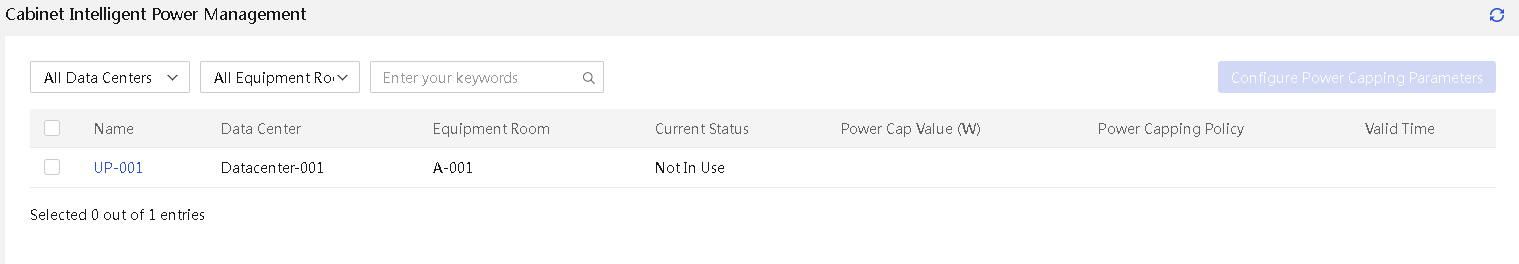
2. Select a cabinet and click Configure Power Capping Parameters. In the dialog box that opens, configure the parameters and click OK.
Figure 253 Configuring power capping parameters
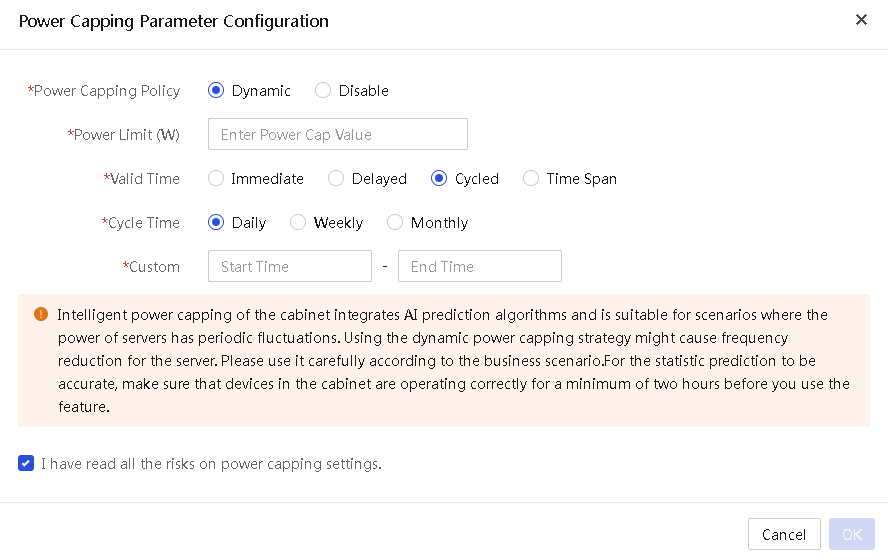
Asset management
The asset management menu provides comprehensive, real-time monitoring and management capabilities through asset overview, asset inventory, and asset inspection, helping users better control and optimize resources. Users can understand detailed asset information and state, monitor device asset changes in real time, and effectively carry out asset inspections and maintenance management to improve asset usage and reduce the operation expenditure.
Asset overview
About this task
Use this feature to view device statistics, component statistics, device change trend, asset change event statistics, recent asset change events, and asset change trends. It helps users promptly understand the usage efficiency and change trend of assets.
Procedure
1. In the navigation pane, select Menu > Asset Management > Asset Overview.
2. View the following information:
¡ Device Statistics: View the total number of current devices, the number of devices of each type, and the changes compared to the previous day.
¡ Component Statistics: View the total number of current components, the number of components of each type, and the changes compared to the previous day. Component types include processor, memory, network adapter, PCIe, fan, power supply, storage controller, FC HBA, drive, and GPU.
¡ Device Change Trend: View the changes of device quantity in each day over the past year.
¡ Asset Change Event Statistics: View the statistical information of asset changes, including the total number of events and the frequency/proportion of each change type.
¡ Recent Asset Change Events: View the most recent five asset change events. The following types of asset change events are available:
- Device Mounting—Add the device to the UniSystem management list.
- Device Removal—Remove the device from the UniSystem management list.
- Component Adding—Install the component to the server.
- Component Removal—Remove the component from the server.
- Firmware Update—Update the HDM (primary partition, golden image, or backup partition), BIOS, ME, system board CPLD, or iFIST firmware.
¡ Asset Change Trend: View the daily asset change frequency over the past year.
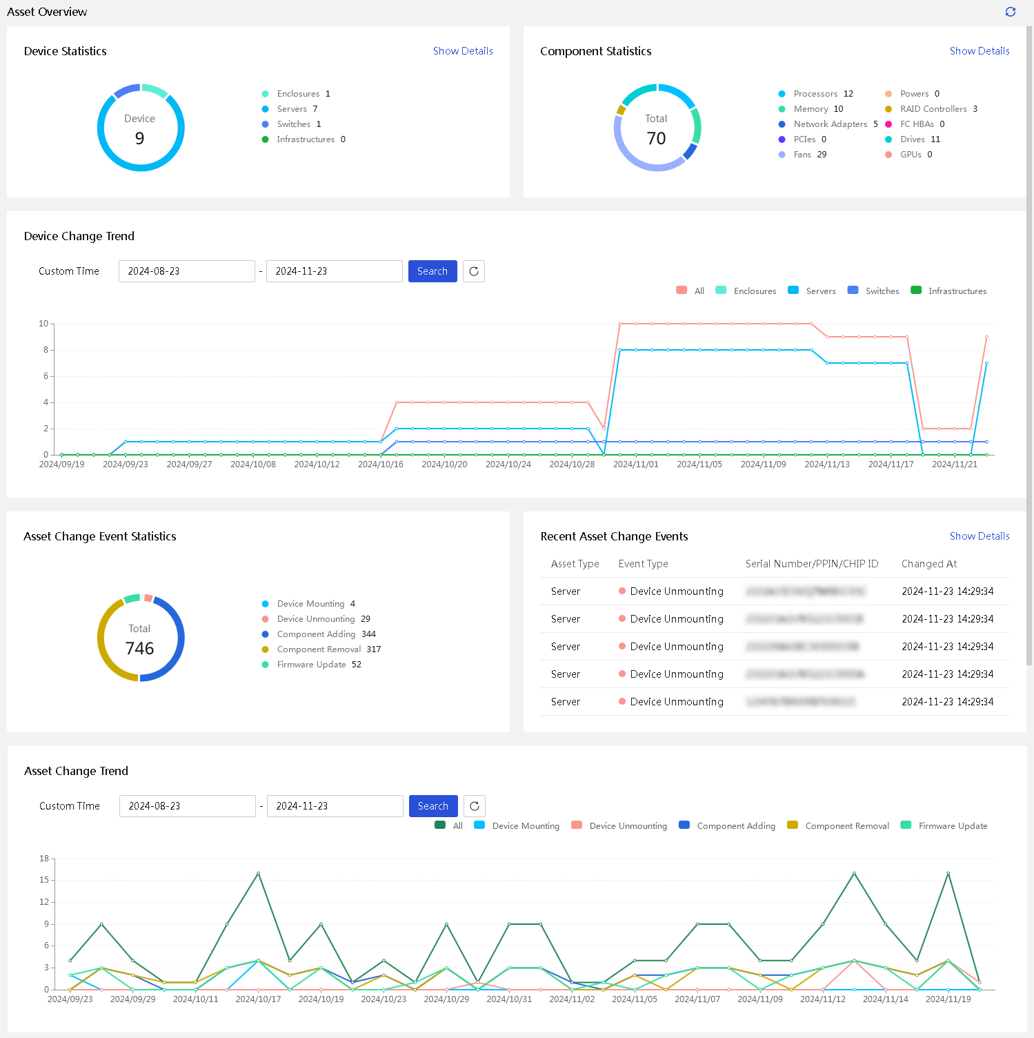
3. To view the details, click View Details in the Device Statistics, Component Statistics, or Recent Asset Change Events section to go to the respective pages.
4. To view statistics in a specific time range, enter a custom time period in the Device Change Trend or Asset Change Trend section and then click Search.
Asset inventory
About this task
UniSystem provides detailed statistics for various devices and components, facilitating management and monitoring of assets in the system.
· Device types include server, enclosure, switch, and infrastructure.
· Component types include processor, memory, drive, network adapter, PCIe, storage controller, GPU, power supply, fan, and FC HBA.
Procedure
1. In the navigation pane, select Menu > Asset Management > Asset Inventory.
2. View server asset inventory information.
a. Click Devices. You are placed on the Servers tab.
Figure 255 Server asset inventory
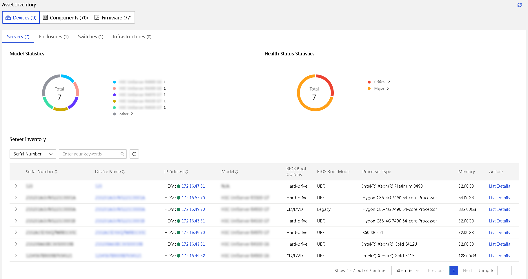
b. Perform the following tasks as needed:
- To view the asset life cycle, click the ![]() icon
at the left of the serial number of a server. You can enter the start and end
time, and click Search to view the corresponding
change records.
icon
at the left of the serial number of a server. You can enter the start and end
time, and click Search to view the corresponding
change records.
- To view the detailed information about a server, click the device name link. For more information, see "View server information."
- To log in to the HDM of a server, click the server IP address link.
- To view the list of components included in a server, click List Details in the Actions column for the server.
3. View enclosure asset inventory information.
a. Click Devices and click the Enclosures tab.
Figure 256 Enclosure asset inventory
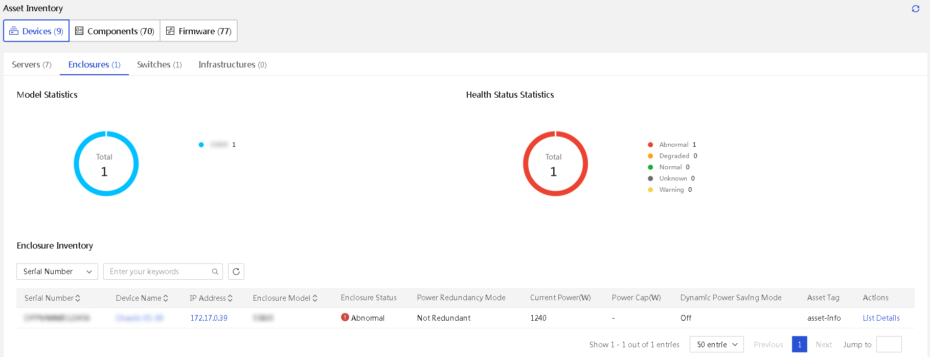
b. Perform the following tasks as needed:
- To view the detailed information about an enclosure, click the device name link.
- To log in to the OM of an enclosure, click the IP address link.
- To view the list of components included in a server, click List Details in the Actions column for the server.
4. View switch asset inventory information.
Click Devices and click the Switches tab.
Figure 257 Switch asset inventory
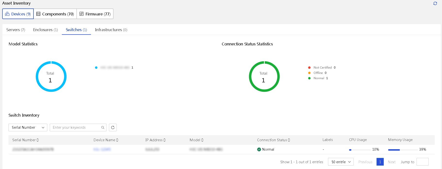
5. View infrastructure asset inventory information.
Click Devices and click the Infrastructures tab.
Figure 258 Infrastructure asset inventory
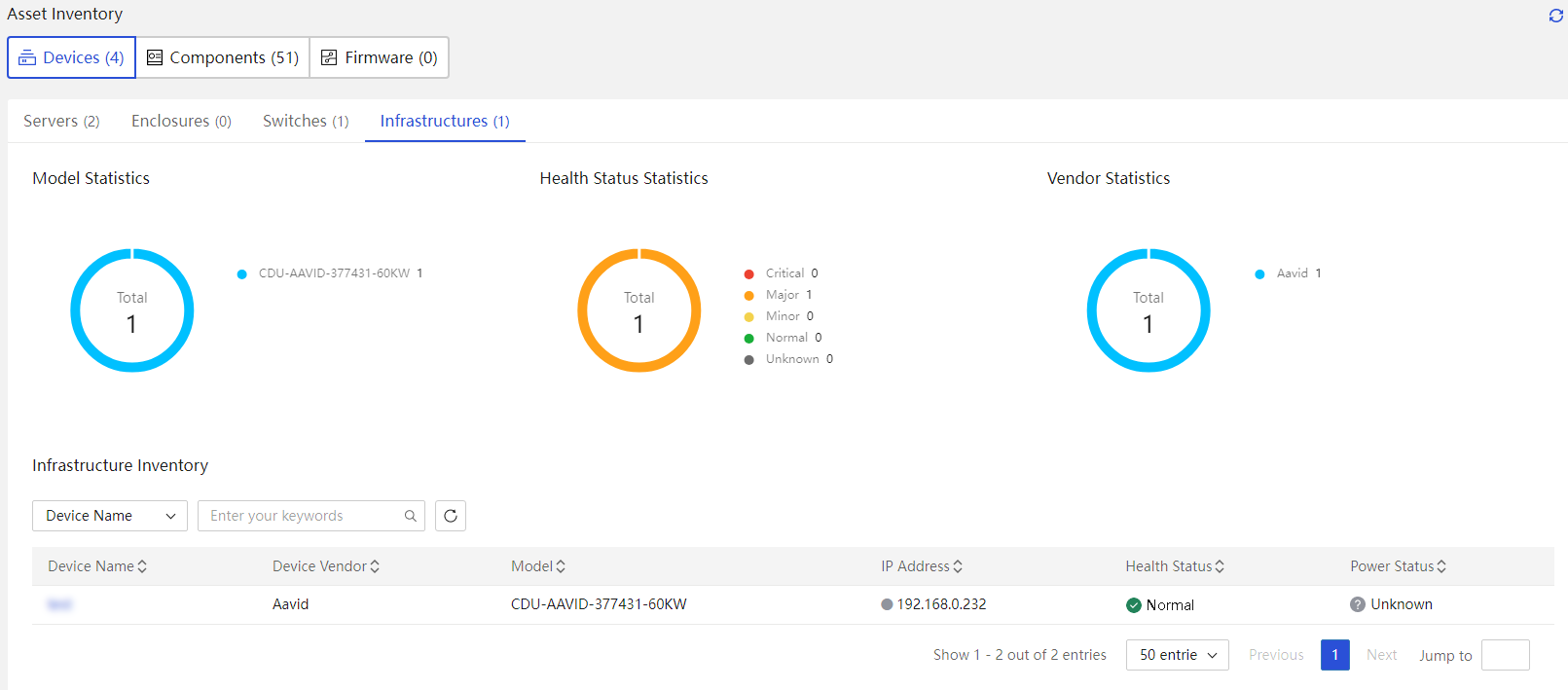
6. View processor asset inventory information.
Click Components. You are placed on the Processors tab.
Figure 259 Processor asset inventory
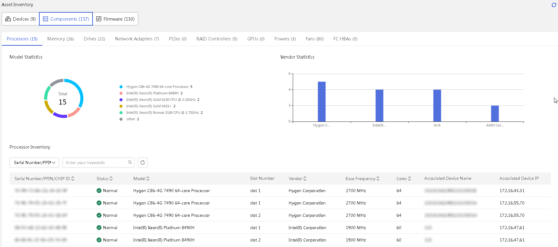
7. View memory asset inventory information.
Click Components and click the Memory tab.
Figure 260 Memory asset inventory
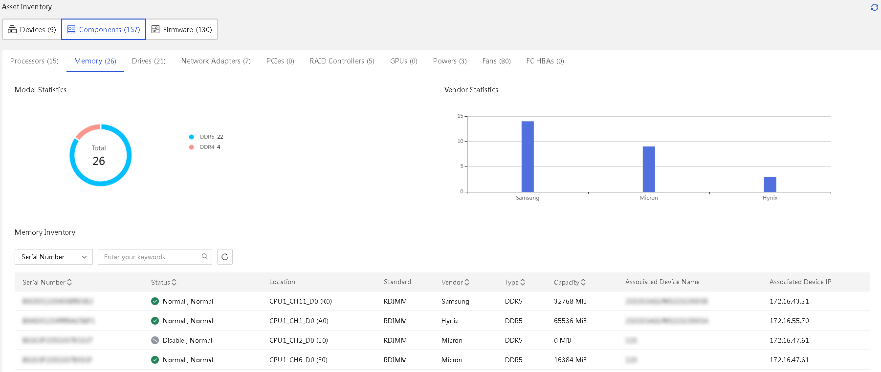
8. View drive asset inventory information.
Click Components and click the Drives tab.
Figure 261 Drive asset inventory
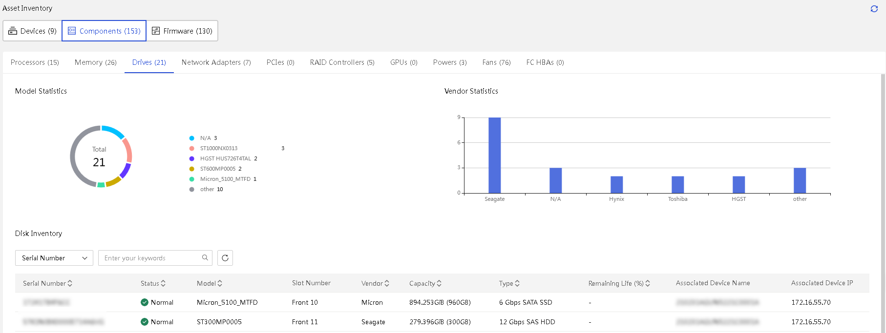
9. View inventory information for network adapter assets.
Click Components and click the Network Adapters tab.
Figure 262 Network adapter asset inventory
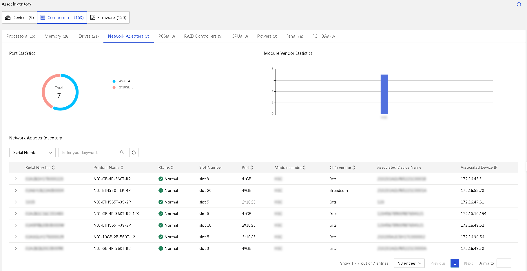
10. View PCIe asset inventory information.
Click Components and click the PCIes tab.
11. View the inventory information for RAID controller assets.
Click Components and click the RAID Controllers tab.
Figure 263 RAID controller asset inventory
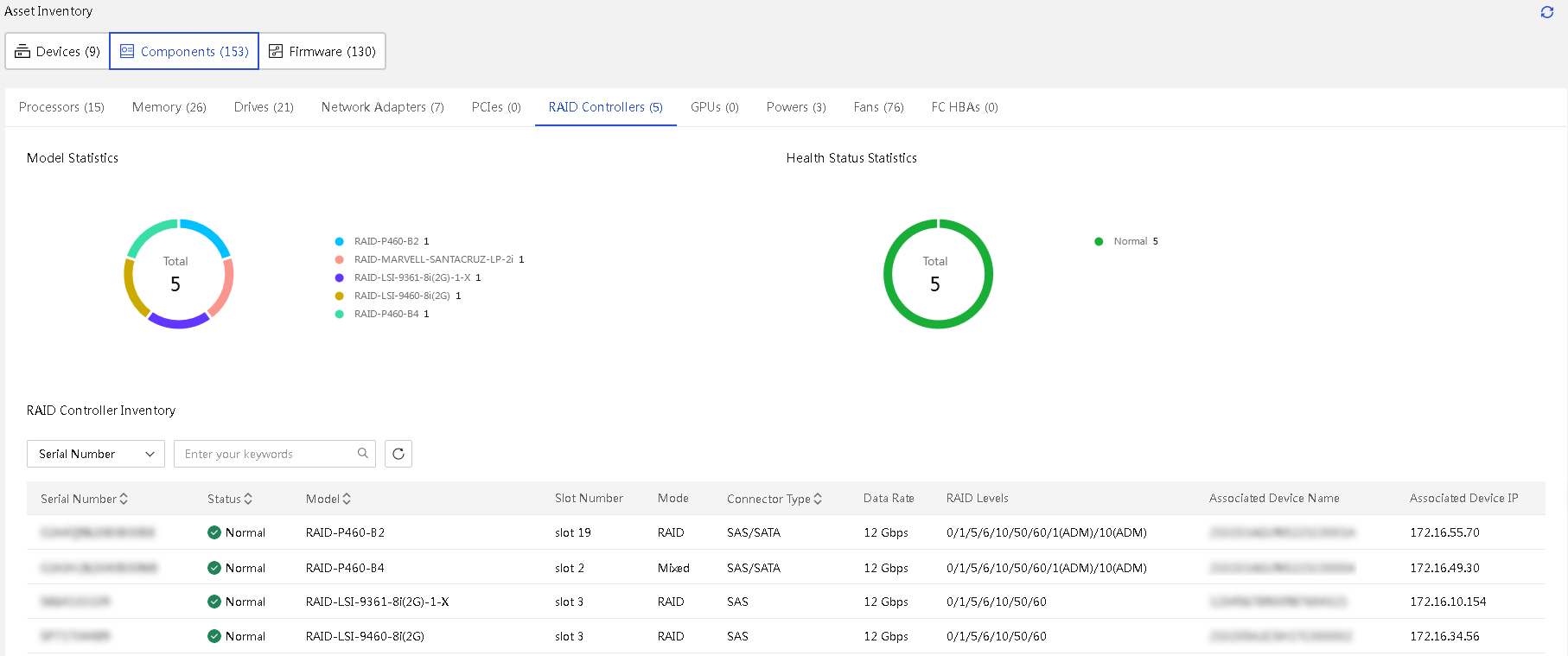
12. View GPU asset inventory information.
Click Components and click the GPUs tab.
13. View the inventory information for power supply assets.
Click Components and click the Power tab.
Figure 264 Power supply asset inventory
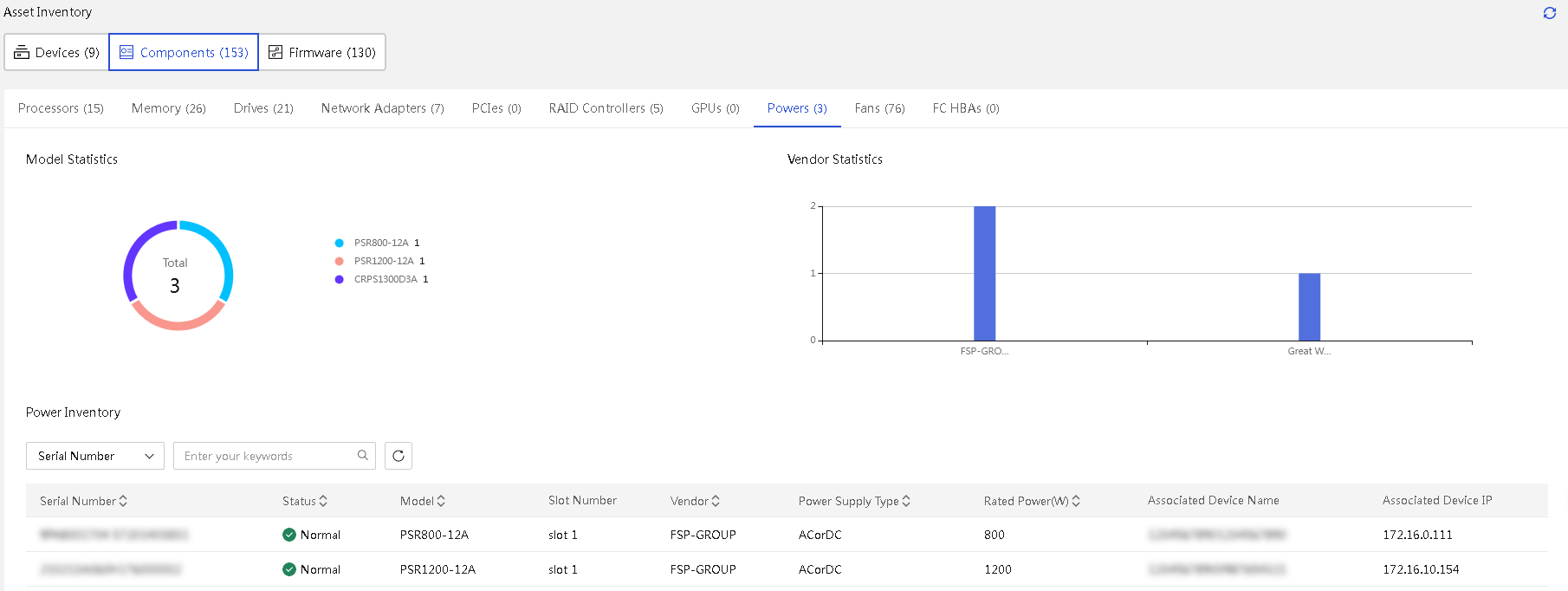
14. View fan asset inventory information.
Click Components and click the Fans tab.
Figure 265 Fan asset inventory
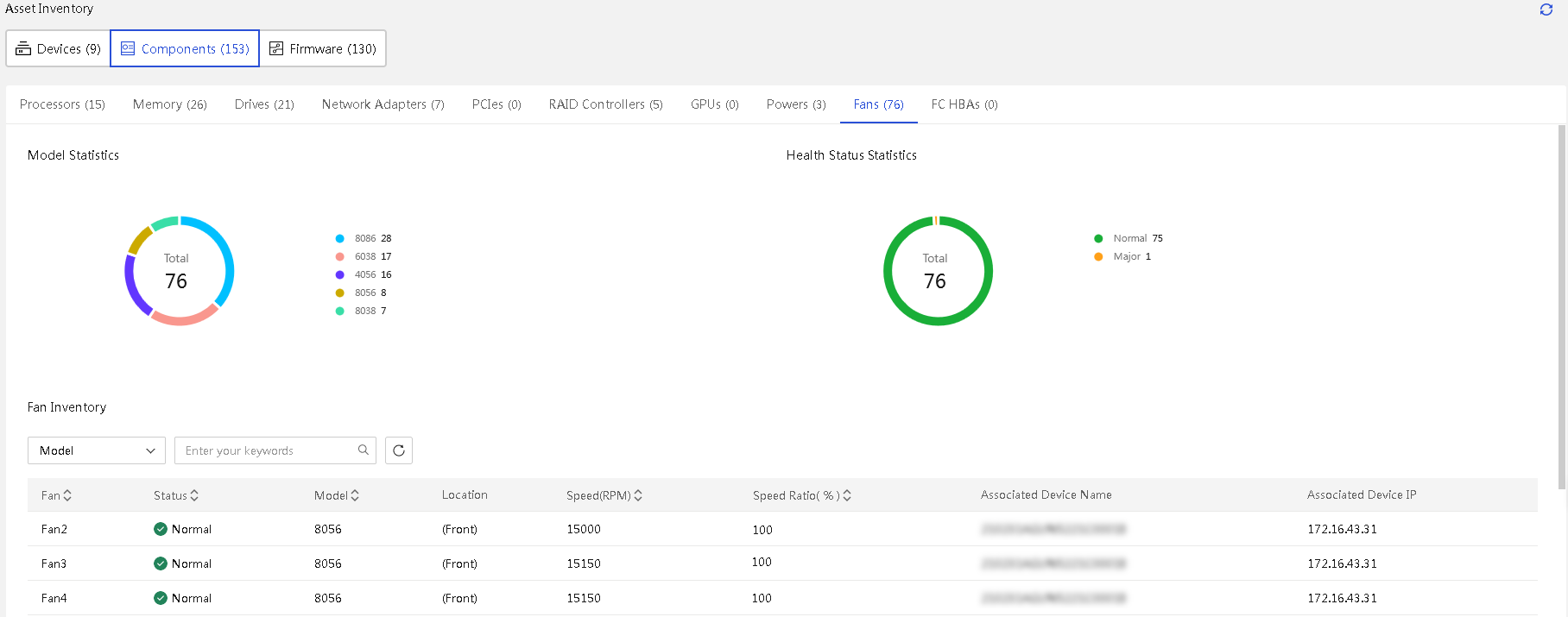
15. View the inventory information for FC HBA assets.
Click Components and click the FC HBAs tab.
16. View the inventory information for firmware, including HDM and the BIOS.
Click Firmware Inventory.
Figure 266 Firmware inventory
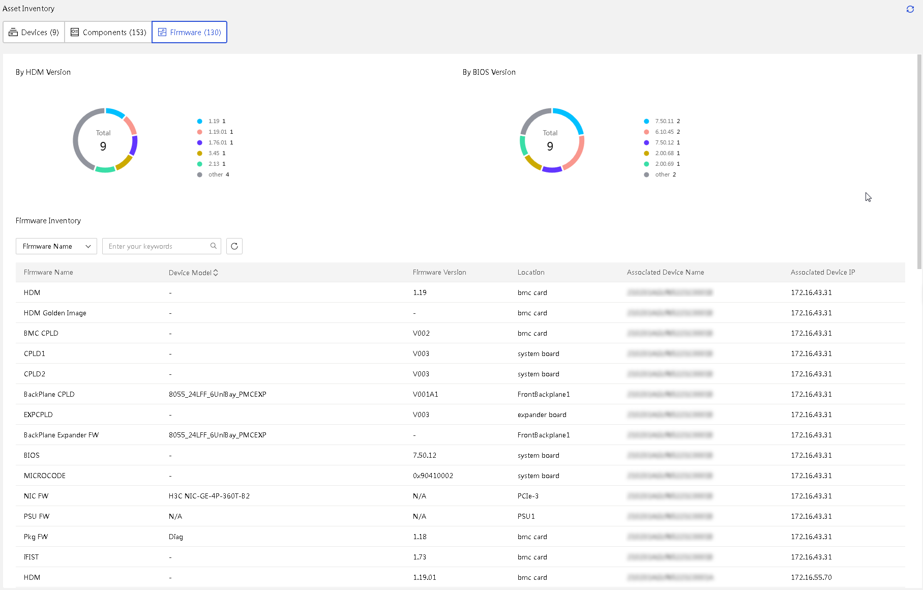
Parameters
· Servers
¡ Serial Number: Serial number of the server.
¡ Device Name: Name of the server.
¡ IP Address: HDM management IP address of the server.
¡ Model: Model of the server.
¡ BIOS Boot Options: BIOS boot option of the server.
¡ BIOS Boot Mode: BIOS boot mode of the server.
¡ Processor Type: Model of the processors on the server.
¡ Memory: Memory capacity of the server.
¡ Firmware: Version information of the HDM (primary and backup partitions), BIOS, ME, system board CPLD, and iFIST firmware.
· Enclosures
¡ Serial Number: Serial number of the enclosure.
¡ Device Name: Device name of the enclosure.
¡ IP Address: Management IP address of the OM module.
· Enclosure Model: Model of the enclosure.
¡ Enclosure Status: Overall health status of the enclosure.
¡ Power Redundancy Mode: Current power redundancy mode of the enclosure. Options include N+1, N+N, and Not Redundant.
¡ Current Power: Total power consumed by all devices in the enclosure.
¡ Power Cap: Power limit value for the enclosure.
¡ Dynamic Power Saving Mode: State of the dynamic power saving mode.
¡ Asset Tag: Asset tag of the enclosure, used to uniquely identify an enclosure.
· Switches
¡ Serial Number: Serial number of the switch.
¡ Device Name: Device name of the switch.
¡ IP Address: Management IP address of the switch.
¡ Model: Model of the switch.
¡ Connection Status: Connection status of the switch. Options include:
- Normal: Successfully logged in.
- Offline: UniSystem is experiencing communication anomalies with the switch.
- Not Certified:
UniSystem communicates normally with the switch. A switch is in the Not
Authenticated state if either of the following conditions exists:
User information (username and password) verification failed. You must update
the user information on UniSystem. For more information, see "Manage switches."
The switch user is not authorized to use the HTTP service.
· Labels: Device label of the switch.
¡ CPU Usage: CPU usage of the switch.
¡ Memory Usage: Memory usage of the switch.
· Infrastructures
¡ Device Name: Device name of the infrastructure.
¡ Device Vendor: Manufacturer of the infrastructure.
¡ Model: Model of the infrastructure.
¡ IP Address: Management IP address of the infrastructure.
¡ Health Status: Heath status of the infrastructure. Options including Unknown, Normal, Minor, Major, and Critical.
Asset changes
About this task
UniSystem offers comprehensive recording and management of device and component changes. Asset changes display the change history of current device assets, including device installation, device removal, component adding, component removal, and firmware updates. This helps track the life cycle and state changes of the device.
Procedure
1. In the navigation pane, select Menu > Asset Management > Asset Changes.
2. Filter asset change records.
¡ Select an event type.
¡ Select
Serial Number or Model,
enter the keywords, and then click the ![]() icon.
icon.
¡ Enter the start time and end time, click Search.
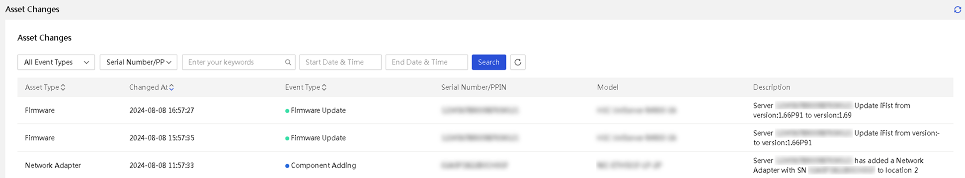
Parameters
· Asset Type: Options include:
¡ Device types: Server, enclosure, switch, and infrastructure.
¡ Component types: Processor, memory, disk, network adapter, PCIe, RAID controller, GPU, power supply, fan, and FC HBA.
· Changed At: Time at which the asset was changed.
· Event Type: Options include the following:
¡ Device Mounting—Add the device to the UniSystem management list.
¡ Device Removal—Remove the device from the UniSystem management list.
¡ Component Adding—Install the component to the server.
¡ Component Removal—Remove the component from the server.
¡ Firmware Update—Update the HDM (primary partition or backup partition), BIOS, ME, system board CPLD, or iFIST firmware.
· Serial Number/PPIN: Serial number or PPIN of the device or component.
· Model: Model of the device or component.
· Description: Description of the asset change.
Asset inspection
About this task
Asset inspection ensures the stable operation of assets by automatically monitoring and checking the health state of devices. Asset inspection provides the following features:
· Configure inspection tasks: Configure an inspection policy to guide inspection, including setting the the inspection state (enabled or disabled), defining the inspection name, specifying the execution time, setting the execution period, selecting device and component types (such as processor, memory, network adapter, PCIe, storage controller, FC-HBA, fan, power supply, drive, GPU, and SNMP Trap), and configuring email contact information to receive inspection reports and notifications.
· View the inspection records: Allow viewing the execution records of executed tasks. The record list includes the serial number, state (success or fail), start time, and completion time, and supports downloading, transmitting, deleting, and detail viewing operations.
· Generate inspection reports: Provides inspection reports to show detailed overview of the device health status. For G6 and above servers, the PDF report also includes processing recommendations for all the unresolved alarms in the event logs. For servers below G6 or when no relevant alarms are found, the system provides default processing recommendations to guide users in troubleshooting hardware issues or contacting technical support.
· Supports automated execution and notification: Support automated execution at the specified time during the set period. At the same time, the system can automatically send inspection reports and alarm notifications to designated email contacts through SMTP, ensuring that users receive device state updates promptly.
Prerequisites
Before configuring this feature, complete the following tasks:
· Complete the SMTP setup. For more information, see "System interfacing."
· If the inspection tasks are performed based on scopes, configure scopes first. For more information, see "Scope management."
View inspecifiction tasks
Procedure
1. In the navigation pane, click Menu > Asset Management > Asset Inspection.
Figure 268 Asset inspection tasks
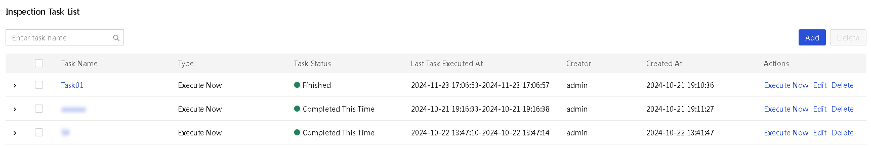
2. View added tasks and task information.
3. To filter tasks, enter the task name, and click the search icon.
4. Click a link in the Actions column to perform the specific task:
¡ To execute a task immediately, click Execute Now.
¡ To edit a task, click Edit.
¡ To delete a task, click Delete.
5. To view the inspection records for a task,
click the ![]() icon for the task and expand the execution history.
icon for the task and expand the execution history.
6. Click a link in the Actions column for a history execution record to perform a specific task:
¡ To view the details for a record, click Details.
¡ To download the compressed report for an execution record, click Download.
¡ To send the report to the contact's email address, click Send.
¡ To delete a history record, click Delete.
Figure 269 Viewing the inspection records
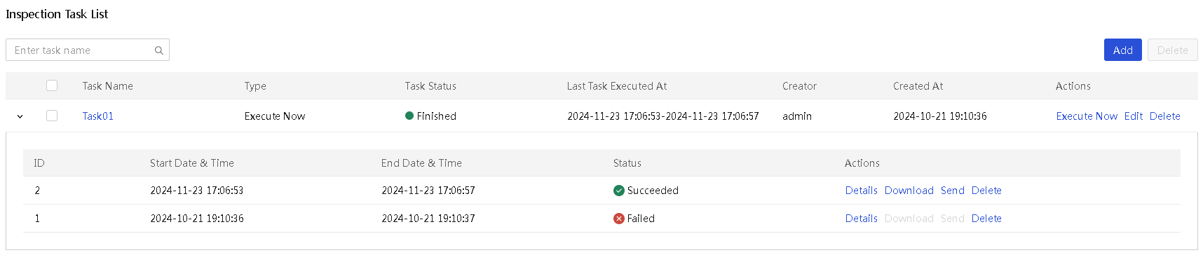
Parameters
· Inspection task parameters
¡ Task Name: Name of the task.
¡ Type: Task execution type, including Execute Now, Execute as Scheduled, and Execute Periodically.
¡ Task Status: Task execution status, including In Process, Pending, Completed This Time, and Completed.
¡ Last Task Executed At: Most recent time at which the task was executed.
¡ Creator: User that created the task.
¡ Created At: Task creation date and time.
· Inspection record parameters
¡ ID: Inspection record ID.
¡ Start Date & Time: Start time and date of the inspection record.
¡ End Date & Time: End time and date of the inspection record.
¡ Status: Execution state: Options include:
- Succeeded.
- Inspecting.
- Failed: You can click the link to view the failure reason.
- Sending failed: The task was executed successfully but the inspection report failed to be sent. As a best practice, check the email configuration.
Restrictions and guidelines
UniSystem supports exporting inspection reports in both Chinese and English. The language of the report matches the language setting used on the Web interface when the inspection strategy is configured.
Add an inspection task
Procedure
1. In the navigation pane, click Menu > Asset Management > Asset Inspection.
2. Click Add and configure the inspection policy as follows:
a. Enter the inspection task name.
b. Select the inspection cycle.
c. Select the inspection device types.
d. Select the device range. Options include:
- Scope: Select the scope to which devices to be inspected belong. You can select multiple scopes.
- Custom: Directly select devices to be inspected. You can select multiple devices.
e. (Optional.) Enter the contact email. After entering a valid email address, you can enable auto sending.
f. To edit SMTP settings, click Edit Settings in the SMTP Settings field.
g. Select the inspection report format. You can select both formats.
h. (Optional.) Enter the inspector information, including the name, phone number, organization name, and organization address.
3. Click OK.
Figure 270 Adding an inspection task
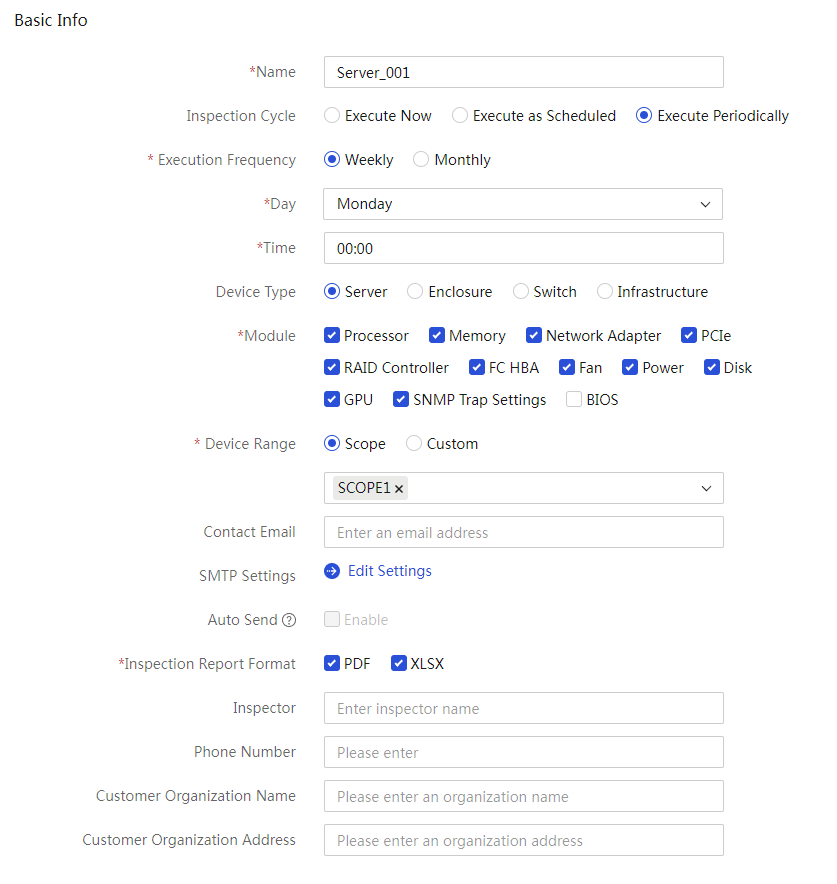
Parameters
· Name: Name of the inspection task.
· Inspection Cycle: Options include:
¡ Execute Now: Execute the inspection task immediately after asset inspection is enabled.
¡ Execute as Scheduled: Execute the inspection task at the set time. You must select the execution time.
¡ Execute Periodically: Execute the inspection task at the specified interval within the specified period. You must specify the execution frequency and period.
· Inspection Device Type: Includes Server, Enclosure, Switch, and Infrastructure.
· Module: Select the modules to be inspected when the inspection device type is Server. Available modules include Processor, Memory, Network Adapter, PCIe, RAID Controller, FC HBA, Fan, Power, Disk, GPU, SNMP Trap Settings, and BIOS.
· Device Range: Select the device range, inclusing Scope and Custom.
· Contact Email: Enter the email address used for receiving the inspection reports.
· Auto Send: Enable the system to automatically send the inspection report to the contact email address upon the completion of the inspection task.
· Inspector: Enter the inspector's name to be displayed in the inspection report.
· Inspection Report Format: Select the inspection report format. Options include PDF and XLSX. If you select the BIOS configuration, the inspection report format only supports XLSX.
· Phone Number: Enter the inspector's phone number to be displayed in the inspection report.
· Customer Organization Name: Enter the customer's organization name to be displayed in the inspection report.
· Customer Organization Address: Enter the customer's organization address to be displayed in the inspection report.
View detailed information about an inspection task
1. In the navigation pane, select Menu > Asset Management > Asset Inspection.
2. Click the name link of the target inspection task and view its details.
Figure 271 Viewing detailed information about an inspection task
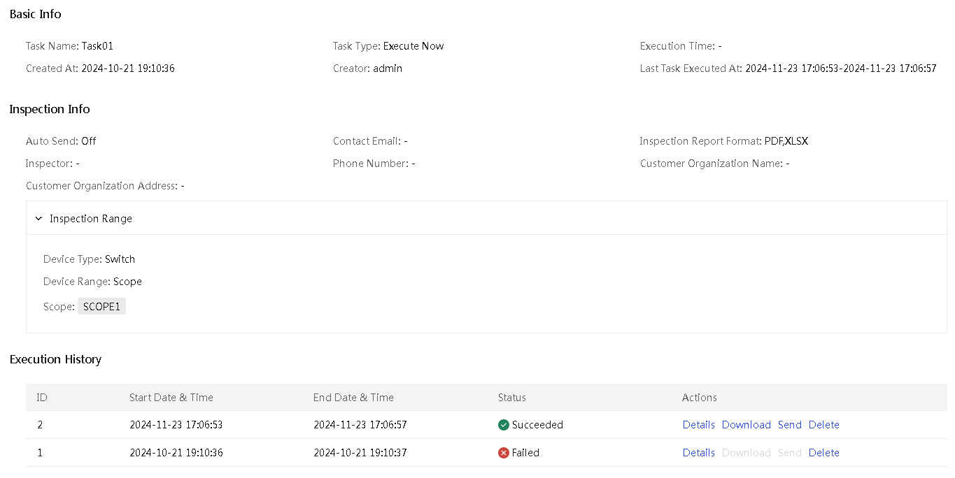
3. To view the ranges of inspected devices,
click the ![]() icon in front of the Inspection Range
section.
icon in front of the Inspection Range
section.
Edit an inspection task
Restrictions and guidelines
When the system is executing an asset inspection task, you cannot edit the task.
Procedure
1. In the navigation pane, click Menu > Asset Management > Asset Inspection.
2. Click Edit in the Actions column for the target task.
3. Edit the task as needed and then click OK.
Delete inspection tasks
Restrictions and guidelines
· You cannot delete a task that is being executed.
· Deleting a task also deletes the related inspection records and reports.
Procedure
1. In the navigation pane, click Menu > Asset Management > Asset Inspection.
2. Perform either of the following to delete inspection tasks:
¡ To delete a specific task, click Delete in the Actions column for the target task.
¡ To delete multiple tasks in bulk, select the tasks, and then click Delete.
Maintenance management
About this task
Maintenance management allows users to manage the maintenance state of servers, stay informed about warranty information, and respond quickly when servers require maintenance or repairs.
Maintenance management provides the following features:
· Maintenance status statistics
UniSystem divides maintenance status into four ranks based on server warranty, and collects statistics on servers in each maintenance status, helping users quickly understand the urgency of server maintenance.
· Maintenance information management
¡ iService Synchronization: Supports automatic batch synchronization of maintenance information for multiple servers from iService, ensuring real-time accuracy of the server maintenance information. When you add a new server, UniSystem automatically retrieves the maintenance information for the server from iService.
¡ Import Data: Supports the manual import of maintenance data in an Excel file, allowing users to flexibly update and maintain server maintenance information without relying on auto synchronization.
¡ Export Data: Supports exporting maintenance data to an Excel file, making it easy to analyze and back up data offline.
· Expiration alarm
UniSystem supports expiration alarm configuration to specify the advance warning days. With expiration alarm enabled, an alarm is triggered if the number of remaining warranty days is less than or equal to the value.
Prerequisites
Before configuring this feature, complete the iService setup first. For more information, see "iService Configuration."
Restrictions and guidelines
· After the server list is updated, the system synchronizes the updates to the maintenance list.
· After a new server is added, the system synchronizes maintenance information with iService within 5 minutes. For iService synchronization to operate normally, configure iService correctly in advance. If auto synchronization fails, update the iService configuration and click iService Synchronization to try again.
· After you enter the Maintenance Management page, the system automatically verifies the iService configuration. If the verification fails, the iService Synchronization button becomes grayed out and unavailable.
Procedure
1. In the navigation pane, select Menu > Asset Management > Maintenance Management.
2. Synchronize iService maintenance information.
In the maintenance list, select the servers to be synchronized, and then click iService Synchronization.
3. Export maintenance data.
In the maintenance list, select the target server, click Export Data. The data will be exported to an Excel and saved locally.
4. Import maintenance data.
a. Click Import Data, download the template, and fill in maintenance information.
b. Click ![]() to select the
completed template.
to select the
completed template.
c. Click Upload. After a successful upload, you can manually synchronize the maintenance information.
5. To configure expiration alarm settings.
a. Click Alarm Configuration.
b. Enable or disable the expiration alarm function.
c. If you select to enable expiration alarm, specify advance warning days.
d. Click OK.
Figure 272 Maintenance management
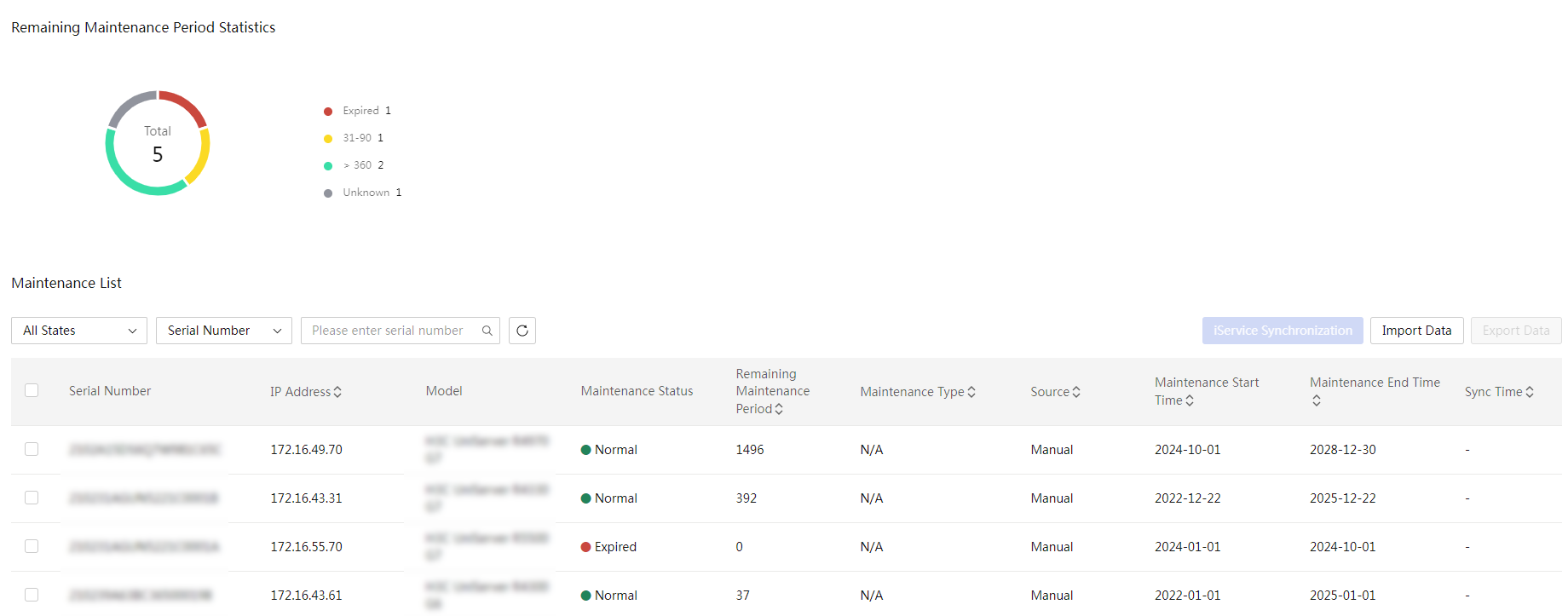
Parameters
· Remaining Maintenance Period Statistics: Total number of servers and server distribution by remaining maintenance period. Types include Expired, < 30, 31-90, 91-180, 181-360, > 360, and Unknown.
· Serial Number: Serial number of the server.
· IP Address: HDM management IP address of the server.
· Model: Model of the server.
· Maintenance Status: The maintenance status can be divided into 4 four categories: Normal, Expire Soon, Expired, and Unknown.
· Remaining Maintenance Period: Remaining maintenance period in days for the server.
· Maintenance Type: Maintenance service level of the server.
· Source: Source of the maintenance information, including Manual and iService.
· Maintenance Start Time: Start time of the server warranty.
· Maintenance End Time: End time of the server warranty.
· Sync Time: Time at which the maintenance information was synchronized.
· Expiration Alarm Configuration (Days): Specify the advance warning days.
Configure tools
Configure the DHCP server
About the DHCP server
|
|
IMPORTANT: Before starting the DHCP server, first check the current LAN configuration, and make sure there are not multiple DHCP servers, which will cause network failure. |
This module allows you to use a DHCP server to automatically allocate an IP address or statically bind an IP address to each client on the same LAN. The IP address can be as an HDM management IP address or system IP address. UniSystem supports the following IP address allocation methods:
· Dynamic method—When a client requests an IP address from the DHCP server, the DHCP server automatically selects an IP address from the IP pool and assigns the IP address to the client.
· Static method—Manually binds an IP address to a client. When the client requests an IP address from the DHCP server, the DHCP server assigns the bound IP address to the client.
The DHCP server feature is exclusive with the DHCP feature in PXE deployment. You cannot configure the two features at the same time because port conflict will occur.
Configure the DHCP server settings
About this task
Perform this task to configure the settings for the DHCP server. You can use the DHCP server to dynamically assign IP addresses to DHCP clients.
Restrictions and guidelines
· If a large number of DHCP clients exist on the network, set the lease time to a greater value.
· For the DHCP server service to start successfully, make sure port number 67 is not being used by another service (for example, dnsmasq).
Procedure
1. In the navigation pane, select Menu > Tools > DHCP Server.
2. Click DHCP Service. In the dialog box that opens, perform the following steps:
a. Select On for DHCP Server.
b. Select the first IP address from the Server IP list.
c. Enter the start IP address and end IP address.
d. Enter the lease time.
e. Enter the gateway address. This field is optional.
Make sure the start IP address and end IP address must be on the same network subnet as the DHCP server.
Figure 273 Configuring the DHCP server
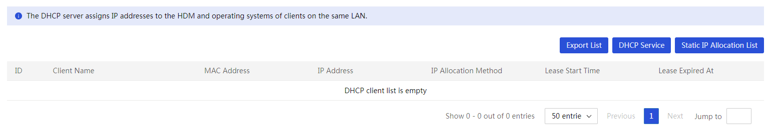
3. Click OK.
View the DHCP client information
About this task
Perform this task to view information about DHCP clients that obtain IP addresses from the DHCP server.
Procedure
1. In the navigation pane, select Menu > Tools > DHCP Server.
2. Click DHCP Service. The page displays information about all DHCP clients.
Figure 274 DHCP client information
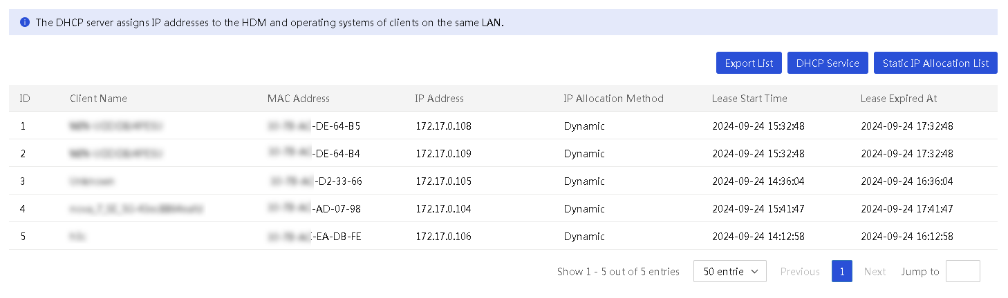
3. (Optional.) If the IP address of a DHCP client is statically assigned by the DHCP server, the Lease Expired At field of this client displays Release. You can click Release to unbind the IP address and the MAC address of the client.
Parameters
· Client Name: Name of a DHCP client.
· MAC Address: MAC address of the DHCP client.
· IP Address: IP address that the DHCP client obtains from the DHCP server.
· IP Allocation Method: Method through which the DHCP client obtains the IP address. Options include:
¡ Dynamic: The DHCP server dynamically selects the IP address from the IP address range to assign to the DHCP client.
¡ Static: The DHCP server statically binds the IP address with the DHCP client.
· Lease Start Time: Time when the DHCP client obtained the IP address.
· Lease Expired At: Time when the IP address expires.
Configure static IP allocation
About this task
This feature allows you to view information about static IP addresses assigned to DHCP clients, to assign a static IP address to a DHCP client, and to release a static IP address.
Restrictions and guidelines
Static IP allocation takes effect only when the DHCP server is enabled.
Procedure
1. In the navigation pane, select Menu > Tools > DHCP Server.
2. Click Static IP Allocation List. The dialog box that opens displays all static IP addresses that have been assigned to DHCP clients.
Figure 275 Static IP Allocation List page
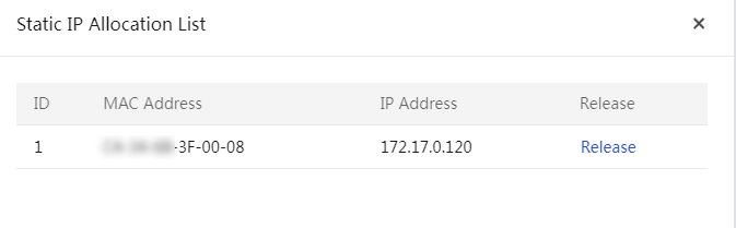
3. (Optional.) To reclaim the IP address assigned to a DHCP client, click Release. In the dialog box that opens, click OK.
4. (Optional.) Click Add to assign a static IP address to a DHCP client. In the dialog box that opens, enter a MAC address and an IP address.
Figure 276 Configuring a static IP allocation

5. Click Add.
Parameters
· MAC Address: MAC address of a DHCP client. The MAC address cannot be a broadcast or multicast MAC address.
· IP Address: IP address statically assigned to the DHCP client. The IP address has the following restrictions:
¡ The IP address must be on the same network segment as the DHCP server but cannot be the same as the DHCP server address.
¡ The IP address can be out of the IP address range specified for the DHCP server.
¡ The IP address cannot be a multicast or broadcast address.
¡ The IP address must be an unused IP address.
Export the IP allocation list
About this task
Perform this task to export the list of IP addresses that have been assigned to DHCP clients to a local file.
Procedure
1. In the navigation pane, select Menu > Tools > DHCP Server.
2. Click Export List. UniSystem exports the statically assigned IP addresses to an EXCEL file.
Configure PXE deployment
About this task
|
|
IMPORTANT: · As a best practice, do not enable the PXE function if you do not need to deploy operating systems through PXE. · If another device is on the same network as UniSystem and the device is configured to obtain an IP address dynamically through DHCP, enabling the PXE function might cause the IP address of the device to change. To avoid affecting other devices on the network, you must isolate the UniSystem network and the network of devices for PXE deployment. |
PXE deployment allows a PXE client to download the OS it requires over the network and then automatically boot and install the OS. This function is available only when UniSystem is running in the AE module.
The PXE deployment process is as follows:
1. A PXE client boots from its own PXE Ethernet adapter, requests an IP address and the location of the boot file from the DHCP server on the network.
2. The DHCP server returns an IP address and the location of the boot file to the PXE client.
3. The PXE client downloads the boot file from the TFTP server on the network and executes the boot file. Based on the execution result of the boot file, the PXE client loads the kernel and file systems from the TFTP server.
4. The PXE client enters the OS installation screen and installs the OS through HTTP.
For RedHat and CentOS installed by using this feature, the default root password is Password@. For other Linux OSs installed by using this feature, the default root password is 123456.
Supported OSs
· CentOS 6.8 (64 bit)
· CentOS 7.2 (64 bit)
· CentOS 7.4 (64 bit)
· Red Hat Enterprise Linux 6.3 (64 bit)
· Red Hat Enterprise Linux 6.8 (64 bit)
· Red Hat Enterprise Linux 7.2 (64 bit)
· Red Hat Enterprise Linux 7.4 (64 bit)
· Red Hat Enterprise Linux 7.5 (64 bit)
Restrictions and guidelines
· A PXE-capable Ethernet adapter is required on the PXE client.
· The PXE client obtains an IP address through the DHCP feature in PXE deployment.
· The IP range does not include a broadcast address.
· The IP addresses in the IP range do not conflict with existing IP addresses on the network.
· PXE deployment uses port numbers 67 and 69 as the DHCP service and the TFTP service, respectively. For PXE deployment to start successfully, make sure port numbers 67 and 69 are not used by other services.
· The DHCP feature in PXE deployment is exclusive with the DHCP server feature. You cannot configure the two features at the same time because port conflict will occur.
· When you install an OS to a blade server through PXE deployment, follow these restrictions and guidelines:
¡ If the iPXE boot loader is used, PXE deployment will fail for a server installed with a mezzanine card and with the legacy boot mode. In this case, use the PXELINUX or GRUB2 boot loader.
¡ The start IP address in the IP range must be on the same subnet as the IP address of network port vmng on the AE module.
¡ The IP range does not include the IP address of network port vmng on the AE module.
¡ IP addresses in the range of 192.250.0.0 through 192.250.255.255 are reserved for internal use. Do not include these IP addresses in the IP range.
Procedure
1. In the navigation pane, select Menu > Tools > PXE Deployment.
Figure 277 PXE deployment page
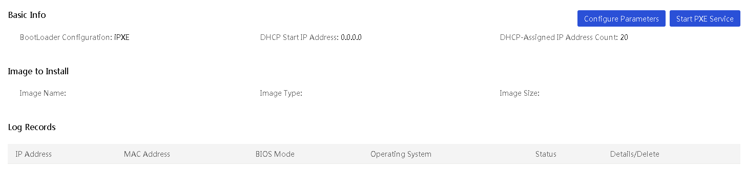
2. Click Configure Parameters, and configure PXE deployment parameters as follows:
a. Select a boot loader configuration mode.
b. Enter the DHCP start IP address and the DHCP-assigned IP address count.
During PXE deployment, the DHCP server will assign an IP address in this range to a server. After the OS installation, the server will use this IP address as the system IP address.
c. Select an image from the image list.
Figure 278 Configuring PXE deployment parameters
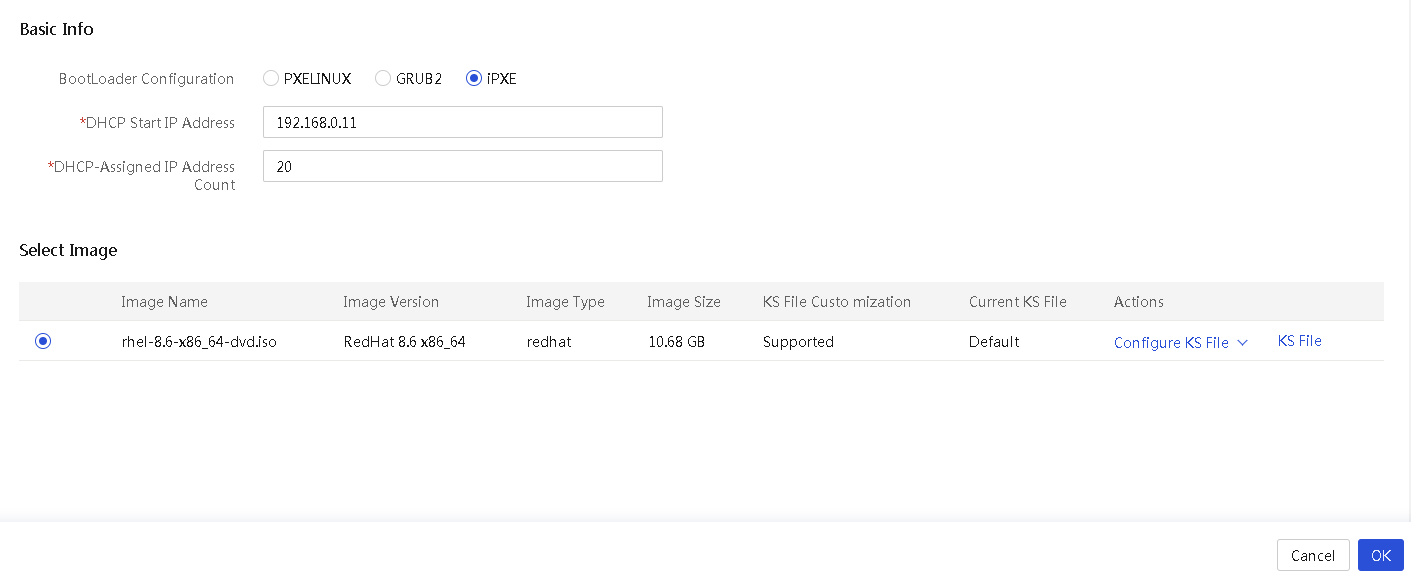
3. Click OK.
Parameters
· BootLoader Configuration: Boot loader of the OS to be installed on a server.
¡ PXELINUX—Derived from SysLinux, PXELINUX enables a client to boot from a network server.
¡ GRUB2—Also referred to GNU GRUB. GRUB2 is a multi-OS boot loader from the GNU project. GRUB2 allows a client to have multiple OSs simultaneously and boot from an expected OS.
¡ iPXE—Provides enhanced PXE implementations. It is compatible with multiple protocols. As a best practice, use iPXE.
· DHCP Start IP Address: First IP address of the IP pool used for IP assignment.
· DHCP-Assigned IP Address Count: Number of IP addresses in the IP pool used for IP assignment.
Configure PXE OS installation parameters
A KS file contains the parameters used by PXE to install the OS for servers, including root password, username, user password, partition settings, software package settings, and language.
UniSystem provides a default KS file that contains PXE-defined default parameters and a custom KS file that allows users to edit the parameters and restore the default settings.
In the current software version, UniSystem supports KS files only for RedHat and CentOS.
Edit the custom KS file
About this task
Perform this task to edit the settings in the custom KS file or restore the default settings of the file.
Procedure
1. In the navigation pane, select Menu > Tools > PXE Deployment.
2. Click Configure Parameters.
3. Select an image, click Configure KS File in the Actions column of the image, and then select Configure Custom KS.
4. On the Edit Custom KS File page, perform one of the following tasks:
¡ To edit the custom KS file manually, edit the parameters as needed, and click OK.
¡ To restore the default settings in the custom KS file, click Restore.
Figure 279 Editing the custom KS file
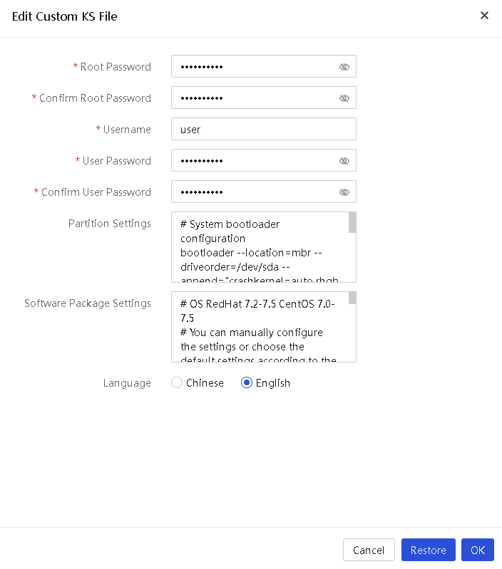
Parameters
· Root Password: Password of the administrator.
· Username: Username of a new user to be created.
· User Password: Password of the user.
· Partition Settings: Partition settings for OS installation.
· Software Package Settings: Settings of the software package used for OS installation.
· Language: Language of the OS to be installed. Options include Chinese and English.
View the default KS file
1. In the navigation pane, select Menu > Tools > PXE Deployment.
2. Click Configure Parameters.
3. Select an image, click Configure KS File in the Actions column of the image, and then select View Default KS.
You can view the settings in the default KS file on the page that opens.
Figure 280 Viewing the default KS file
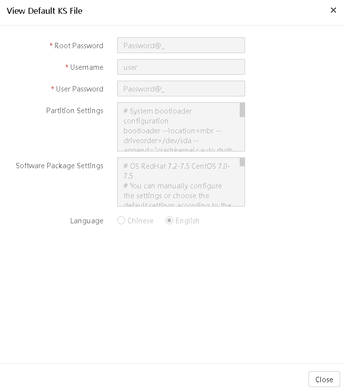
Apply a KS file
1. In the navigation pane, select Menu > Tools > PXE Deployment.
2. Click Configure Parameters.
3. Select an image, and click KS File in the Actions column of the image.
4. Select a KS file. Options include default and custom. PXE will use the settings in the specified KS file to install the OS for servers.
Figure 281 Applying a KS file
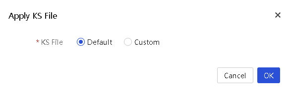
Restrictions and guidelines
· The custom KS file is automatically generated when the system uploads the OS software image. The parameter settings in the custom KS file are the same as those in the default KS file.
· For an OS in use, you cannot edit the custom KS file or restore the default settings of the KS file.
· During configuration restoration, UniSystem will restore the custom KS file if the image name and OS version of the custom KS file are the same as those in the configuration file used for restoration.
Push and install software
About this task
This module allows you to remotely install FIST SMS or general software to the OSs of the servers managed by UniSystem.
FIST SMS is the software installed in the OS of the managed servers to enhance the HDM and UniSystem management. After FIST SMS is successfully installed in the OS of a server, FIST SMS will run automatically and UniSystem will add this server as a FIST SMS device.
General software refers to any software you want to install in UniSystem. This feature pushes the software installation package and installs script to the OS of a server and installs the software by executing the install script.
|
|
NOTE: · The FIST SMS installation feature is available in version 2.00.16 and later versions. · The general software installation feature is available in version 2.00.33 and later. · This feature supports only FIST SMS-1.03.08 and later versions. |
Restrictions and guidelines
To avoid FIST SMS installation failure, do not make any changes to the installation package.
If the firewall feature is enabled on a server, the system automatically performs the following tasks after installing FIST SMS on the server:
· Adds the ports used by FIST SMS (ports 12580 and 6900) to the allowlist of the firewall. The ports will remain on the allowlist even after the FIST SMS server reboots.
· Enables the ICMPv4-In rule in the firewall settings so the FIST SMS server can be managed by UniSystem.
Prerequisites
To install FIST SMS, follow these guidelines:
· Install OpenJDK 1.8 (64-bit) on the server to be installed with FIST SMS. As from FIST SMS-1.37, if you install FIST SMS to a Window operating system, you do not need to configure the OpenJDK software in advance.
· To start FIST SMS successfully, use port 12580 only for FIST SMS.
· Verify that the winrm service is correctly configured on a Windows server or the sshd service has started on a Linux server.
To install general software, follow these guidelines:
· Prepare the software installation package and install script in advance and package them together into an installation file in the .tar.gz format.
· You might fail to install general software because of the following reasons:
¡ The running time of the install script exceeds the upper limit. The running time upper limit of the install script is 20 seconds in the Windows system and 20 minutes in the Linux system.
¡ The install script contains interactive statements, such as the pause statement.
· The extension of the install script varies by OS type.
¡ In the Windows operating system, the install script must be named as install.bat.
¡ In the Linux operating system, the install script must be named as install.sh.
· Verify that the winrm service is correctly configured on a Windows server or the sshd service has started on a Linux server.
Verify the winrm service status on a Windows server
1. Log in to the Windows system as an administrator and start PowerShell.
2. Execute the Get-Service winrm command to check the status of the winrm service.
¡ No actions are required if the service status is Running.
¡ Proceed to the next step if the service status is Stopped.
Figure 282 Checking the winrm service status
3. Execute the winrm quickconfig command to start the winrm service.
Figure 283 Starting the winrm service
4. Execute the winrm set winrm/config/service '@{AllowUnencrypted="true"}' command to allow unencrypted transmission.
Figure 284 Allowing unencrypted transmission
5. Execute the winrm set winrm/config/winrs '@{MaxMemoryPerShellMB="memory-size"}' command to set the maximum PowerShell memory size to a value greater than 1/16 of the server's physical memory.
Figure 285 Setting the maximum PowerShell memory
Verify the sshd service status on a Linux server
1. Log in to the Linux system as an administrator.
2. Install the sshd service and execute the service sshd start command to start the service. If the service has been installed, execute the service sshd status command to check the sshd service status.
¡ No actions are required if the service status is active.
¡ Proceed to the next step if the service status is inactive.
Figure 286 Checking the sshd service status
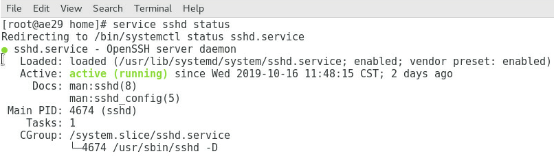
3. Execute the service sshd start command to start the sshd service. If the system prompts that sshd is not installed.
Configure the VMware ESXi host
Enable the SSH service
When installing software on a VMware ESXi host, follow these steps to allow the use of SSH:
1. Log in to the VMware ESXi host using the vSphere client as an administrator.
2. In the left navigation pane, select Host.
Figure 287 Enabling the SSH service
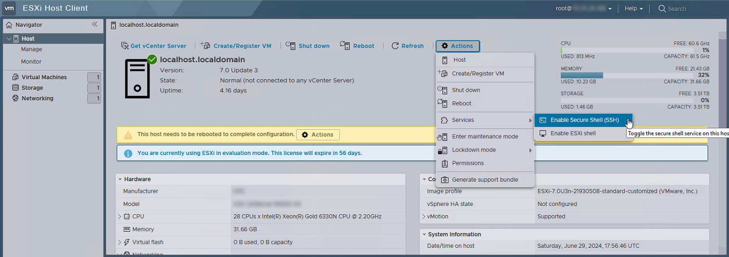
3. Select Actions > Services > Enable Secure Shell (SSH).
4. Once the SSH service is started, you can use the SSH client to connect to the ESXi host.
Disable execInstalledOnly
When installing software on the VMware ESXi operating system, you must disable the execInstalledOnly option. To disable execInstalledOnly:
1. Log in to the VMware ESXi host using the vSphere client as an administrator.
2. In the left navigation pane, select Host > Manage > System.
3. Select VMkernel.Boot.execInstalledOnly and click Edit.
4. Select False and click Save.
Figure 288 Disabling execInstalledOnly
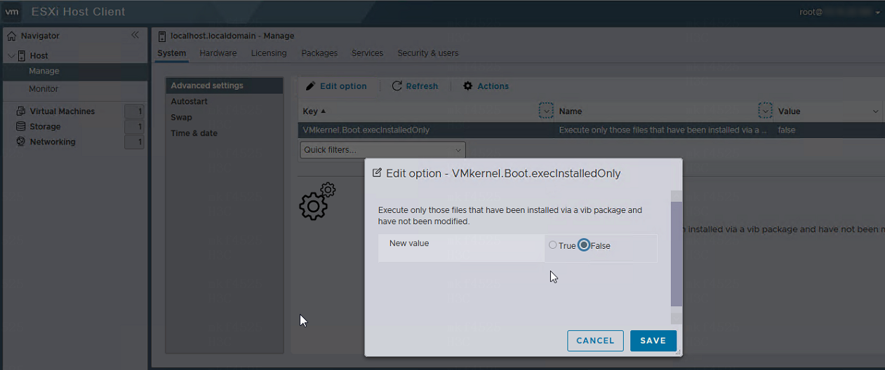
Procedure
1. In the navigation pane, select Menu > Tools > Push and Install Software.
2. Select an installation file type.
3. To upload a device list, perform the following steps:
a. (Optional.) Click Download Template under Device List File to download the device list template, and edit the devices in the device list template.
b. Click … in the Device List File field.
c. In the dialog box that opens, click Browse, select a device list file, and then click OK.
d. Click Upload. The Device List area displays the list of devices to which you can install FIST SMS or general software.
Figure 289 Installing FIST SMS
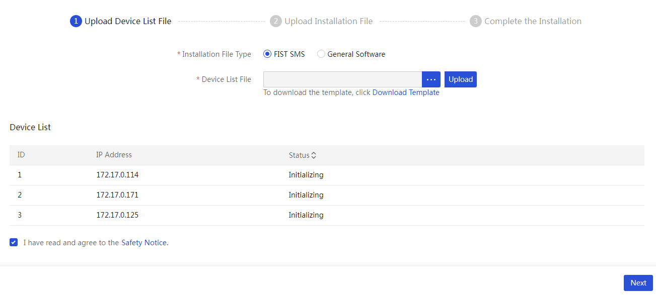
4. Click Next.
5. To upload a FIST SMS or general software installation file or FIST SMS driver file, perform the following tasks:
a. Click … in the FIST SMS Installation File, General Software Installation File, or FIST SMS Driver File field.
b. In the dialogue box that opens, click Browse, select the target file, and then click OK.
c. Click Upload. The system displays the name of the uploaded file.
Figure 290 Uploading the installation file
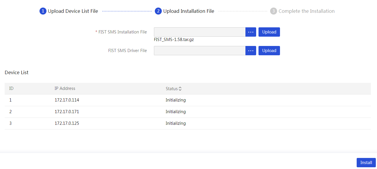
6. Click Install. The system starts to install FIST SMS or general software on the servers in the device list. It will take a long time, please wait for the process to finish.
After you install general software successfully, you can view the information in the Logs column. To view detailed logs, you can select devices in the device list and then click Download.
7. Click Finish.
Remote commands
|
|
NOTE: Only the default admin user and users with the administrator role and permissions over all resources support this feature. |
This feature helps users query and obtain basic device information to meet the need for bulk command execution, such as bulk power-on and bulk power-off. This feature allows users to execute tasks or obtain information without switching management software or tools. This enhances O&M capabilities and user experience for the management software.
Ping commands
About this task
Ping is a tool for testing network connectivity by sending data packets to a target device and waiting for its response to assess the network connection.
Procedure
1. In the navigation pane, select Menu > Tools > Remote Commands. Then, click Ping Commands.
2. Enter an IP address for the Execute Commands field.
3. Click Execute. Then, wait for the execution to finish.
The execution result will be displayed below the Execute button.
4. To clear the execution result, click Clear.
Restrictions and guidelines
· Ping commands support IPv4, IPv6, and fe80 addresses, but do not support domain addresses.
· Ping commands support Windows and Linux.
· The execution result of a ping command is temporary data. Once you refresh the page, the execution result will be cleared.
IPMI commands
This feature allows you to execute IPMI commands remotely for devices. You can execute IPMI commands on multiple devices in bulk. This feature allows users to easily manage and monitor remote devices, execute IPMI commands such as reboot, power control, and temperature sensor queries, enabling remote operation and management of devices.
Procedure
1. In the navigation pane, select Menu > Tools > Remote Commands. Then, click IPMI Commands.
2. Enter only the command part of an IPMI command for the Execute Commands field.
¡ To
add a command part, first click ![]() to add a new
input box.
to add a new
input box.
¡ To
delete an input box, click the ![]() icon.
icon.
3. Click Select. On the page that opens, select the check box next to device names in the list to add the devices, and then click OK.
4. Click Execute. Then, wait for the execution to finish. The device list will be updated.
5. To view the detailed execution result for a device, click the arrow icon next to the IP address of the device in the list.
6. To export the execution result to an Excel file, click Export Result.
7. To clear the execution result, click Clear.
Restrictions and guidelines
· You can execute up to three commands at a time. The system does not verify the validity of these commands.
· You can select up to 100 devices when you execute IPMI commands at a time.
· After an IPMI command is executed, the system will temporarily save historical data for future query. Clicking Clear or restarting the service will clear the historical data. To execute another IPMI command, you must first clear the historical data.
Redfish commands
This feature allows you to execute Redfish commands remotely for devices. You can execute Redfish commands on multiple devices in bulk. After executing the Redfish command, the system will display the results and offer an export function, making it easy for users to conduct further analysis and processing.
Procedure
1. In the navigation pane, select Menu > Tools > Remote Commands. Then, click Redfish Commands.
2. Select a command type.
3. Enter only the command part of a Redfish command.
4. If you select a command type except GET, enter a request parameter in JSON format for the Request Parameter field.
5. Click Select. On the page that opens, select the check box next to device names in the list to add the devices, and then click OK.
6. Click Execute. Then, wait for the execution to finish. The device list will be updated.
7. To view the detailed execution result for a
device, click the ![]() icon next to the IP address of the device in the list.
icon next to the IP address of the device in the list.
8. To export the execution result to an Excel file, click Export Result.
9. To clear the execution result, click Clear.
Restrictions and guidelines
· Only one Redfish command can be executed at a time. You can select up to 100 online devices (G6 or later) for one Redfish command.
· After a Redfish command is executed, the system temporarily saves historical data for future query. Clicking Clear or restarting the service will clear the historical data. To execute another Redfish command, you must first clear the historical data.
· The request parameter in a Redfish command is in JSON format. As a best practice, specify a request parameter according to the related Redfish documentation.
Incorporate UniSystem to vCenter Server as a UniSystem plugin
About this feature
You can incorporate UniSystem as a plugin to vCenter Server. After that, you can access UniSystem through vSphere Client, an application that allows you to connect directly to a vCenter Server instance.
Prerequisites
Obtain the IP address, login username, and password of the vCenter Server.
Restrictions and guidelines
· If you use Google Chrome 85 or a later version, enter chrome://flags/#same-site-by-default-cookies in the address bar to disable the SameSite by default cookies feature, as shown in Figure 291. If you got stuck in the UniSystem login process by using another browser, try editing the browser cache settings in a similar way.
Figure 291 Editing the browser cache settings
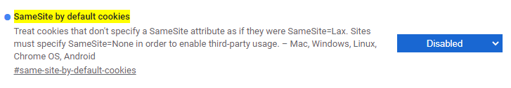
· After UniSystem registration is complete, if you need to register UniSystem of an earlier version or the same version again, uninstall the registered UniSystem plugin first. If you register UniSystem directly without uninstalling the previously registered UniSystem plugin, vCenter Server will not deploy the newly registered UniSystem plugin.
Installing the UniSystem plugin
1. Enter https://UniSystem ip address:https port in the address bar to log in to UniSystem. Then, enter https://UniSystem ip address:https port/server/0/register-plugin in the address bar to access the Register Plugin page, as shown in Figure 292.
|
|
IMPORTANT: To ensure normal access to UniSystem after UniSystem plugin registration, log in to UniSystem through HTTPS. |
Figure 292 Register Plugin page
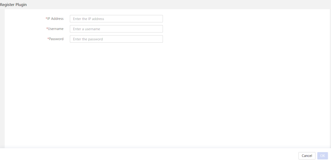
2. Enter the IP address, username, and password of the vCenter Server, and then click OK.
3. After the registration is complete, log in to vSphere Client. Click the UniSystem icon on the Shortcuts page to access UniSystem through vSphere Client.
Uninstalling the UniSystem plugin
Uninstalling the UniSystem plugin from vCenter 7.0
To uninstall the deployed UniSystem plugin, use the vSphere Client SDK provided by vCenter Server (access the page at https://www.vmware.com/support/developer/webclient/index.html for more information). Use the extension-registration tool for the uninstallation.
· Command for uninstalling the UniSystem plugin:
$tools/extension-registration.bat -action unregisterPlugin -k sample.plugin -url https://vc-svr.example.com/sdk -u [email protected] -p secret
· Command parameter descriptions:
¡ -action: Specify the action to execute, which is unregisterPlugin in this example.
¡ -k sample.plugin: Specify the identifier of the target plugin, which is com.h3c.fist.localui in this example.
¡ -url https://vc-svr.example.com/sdk: Specify the URL of the SDK resources provided by vCenter Server, for example, https://192.168.128.117/sdk.
¡ -u [email protected]: Specify the login username of vCenter Server.
¡ -p secret: Specify the login password of vCenter Server.
· Command example for uninstalling UniSystem plugin:
D:\vsphere-client-sdk-6.7.0.40000-14186396\html-client-sdk\tools\vCenter plugin registration\prebuilt>extension-registration.bat -action unregisterPlugin -k com.h3c.fist.localui -u [email protected] -p ***** -url https:// 192.168.128.117/sdk
Uninstalling the UniSystem plugin from vCenter 8.0
To uninstall the deployed UniSystem plugin, use the vSphere Client SDK provided by vCenter Server (access the page at https://www.vmware.com/support/developer/webclient/index.html for more information). Use the extension-registration tool for the uninstallation.
· Command for uninstalling the UniSystem plugin:
$tools/extension-registration.bat -action unregisterPlugin -k sample.plugin -url https://vc-svr.example.com/sdk -u [email protected] -p secret -vct vcenterServerThumbprint
· Command parameter descriptions:
¡ -action: Specify the action to execute, which is unregisterPlugin in this example.
¡ -k sample.plugin: Specify the identifier of the target plugin, which is com.h3c.unisystem.remote in this example.
¡ -url https://vc-svr.example.com/sdk: Specify the URL of the SDK resources provided by vCenter Server, for example, https://192.168.128.117/sdk.
¡ -u [email protected]: Specify the login username of vCenter Server.
¡ -p secret: Specify the login password of vCenter Server.
¡ -vct vcenterServerThumbprin: Plugin fingerprint of vCenter Server.
· Command example for uninstalling UniSystem plugin:
D:\vsphere-client-sdk-6.7.0.40000-14186396\html-client-sdk\tools\vCenter plugin registration\prebuilt>extension-registration.bat -action unregisterPlugin -k com.h3c.unisystem.remote -u [email protected] -p***** -url https://192.168.21.27/sdk -vct C2:74:43:D2:1F:9D:CC:52:E5:6A:98:DF:50:C7:ED:0E:60:FD:B7:1C:F7:D6:8F:D6:E3:90:6C:3C:A8:2C:B5:1E
Configure the system settings
Configure the network settings
This module is available only when UniSystem runs on an AE module or VM.
This module allows you to view basic Ethernet adapter module information and routing entries, manage the IP address of the network ports, and test the network connectivity.
As shown in Figure 293, the AE module has a GE Ethernet adapter and a 10-GE Ethernet adapter. Two GE interfaces of the GE Ethernet adapter connect to OM module 1 and OM module 2, respectively. Two 10-GE interfaces of the 10-GE Ethernet adapters connect to interconnect module 1 and interconnect module 4, respectively.
Figure 293 Connections between modules in a server enclosure

View basic Ethernet adapter information
Perform this task to view the basic information of the Ethernet adapter modules on the UniSystem server.
If the UniSystem server runs on an AE module, the following network ports are available:
· vmng—Aggregate interface of which the member ports are the network ports of the OM modules. The network port belongs to VLAN 1.
· vmng.om—Virtual network port used to communicate with an OM module. The virtual network port belongs to 4094.
· enp5s0f0—Network port connected to interconnect module 1.
· enp5s0f1—Network port connected to interconnect module 4.
Procedure
1. In the navigation pane, select Menu > System > System > Network.
2. View basic information of the Ethernet adapter modules. For more information about the parameters, see the online help.
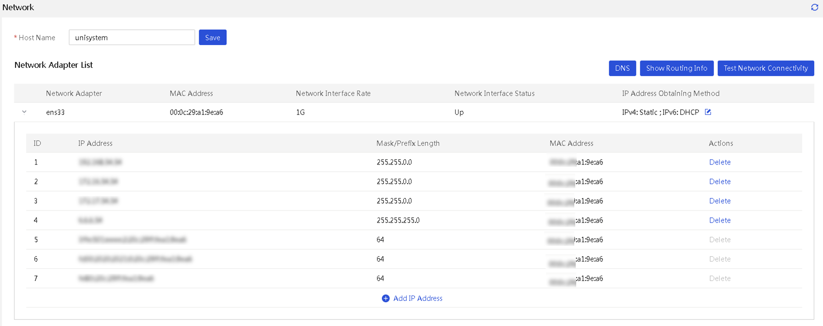
Set the host name for UniSystem
Perform this task to view or set the host name used for the UniSystem server. This feature is available only when the UniSystem server runs on an AE module.
Procedure
1. In the navigation pane, select Menu > System > System > Network.
2. Enter the host name.
3. Click Save.
Set the IP address obtaining method for a network port and the DNS server address
Both static and DHCP methods are supported for configuring IPv4 and IPv6 addresses. When the IP address obtaining method for the network port is set to DHCP, you can enable DHCP/DHCPv6 to obtain the DNS server address. When the IP address obtaining method is set to static, you must manually configure the DNS server address.
When the DHCP method is used, the network adapter sends DHCP requests. Then, manually click the refresh button to display the new IP address on the page. For IPv4 DHCP, if an anomaly occurs in communication with the DHCP server, the system will automatically switch to static mode after waiting for about 1 minute.
Some features of UniSystem require Internet access, so the server needs to use a DNS server to resolve domain names. To ensure the correct operation of the network environment, configure the DNS server based on the actual circumstances.
Restrictions and guidelines
If you set the IP address obtaining method to DHCP for a network port, the network port will no longer use the static IP address. If you restore the method to static, the network port will use the previously specified static IP address.
Procedure
1. In the navigation pane, select Menu > System > System > Network.
2. Click the ![]() button of a
network port. In the dialog box that opens, set the IP address obtaining method
and DNS address obtaining method, and then click OK.
button of a
network port. In the dialog box that opens, set the IP address obtaining method
and DNS address obtaining method, and then click OK.
¡ If you select the DHCP mode, you can select whether to use DHCP/DHCPv6 to obtain DNS server addresses.
¡ If you select the static mode, you must manually enter the IP address of the DNS server.
3. Click OK.
4. Click Add New IP of a network port. In the dialog box that opens, select IPv4 or IPv6, and enter an IP address and subnet mask or prefix length. Click OK.
|
|
NOTE: When adding an IPv6 address, you cannot add an IPv6 address embedded with an IPv4 address (for example, ::192.168.0.1 ) or an IPv6 address that can be abbreviated into an address seemingly embedded with an IPv4 address (for example, ::c3:3). |
5. To delete an IP address of a network port, click Delete in the Actions column, and then click OK. You cannot edit or delete a link-local address.
View DNS information
About this task
This feature is available in version 2.34 and later.
Perform this task to view DNS server information.
Procedure
1. In the navigation pane, select Menu > System > System > Network.
2. Click DNS.
Figure 295 View DNS information
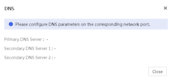
3. In the dialog box that opens, view DNS server information.
Test the network connectivity
Perform this task to test the network connectivity between the UniSystem server and an IP address and view the routing entries of the UniSystem server.
Procedure
1. In the navigation pane, select Menu > System > System > Network.
2. Click Test Network Connectivity and enter an IP address.
3. Click Ping. View the returned ping result.
4. (Optional.) Click Show Routing Info to view the routing information.
Configuring proxy settings
About this task
This feature is available in version 2.34 and later.
This module allows you to configure a proxy server. Thus, UniSystem can use the HTTP or HTTPS protocol for external communication.
In the current software version, UniSystem can use the proxy server only for the following features:
· Add the UniSystem-type repositories in the repository library, and enable REPO update.
· Configure WeCom notification, SMS notification, or voice notification.
· Configure repair reporting in remote support.
By default, no proxy is used when you use other features except for the above features in UniSystem.
Procedure
1. In the navigation pane, select Menu > System > System > Proxy Settings.
Figure 296 Configuring proxy settings
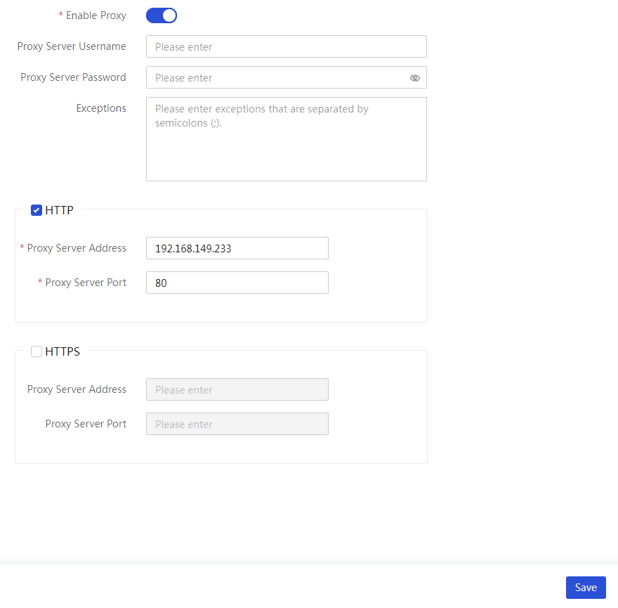
2. Select whether to enable proxy.
3. Enter the proxy server parameters.
4. (Optional.) Select HTTP to enable HTTP proxy.
5. (Optional.) Select HTTPS to enable HTTPS proxy.
6. Click Save.
Configure the system time
About this task
This feature is available in version 2.00.17 and later.
This module allows you to view or set the system time of UniSystem. This feature is available only when UniSystem runs on an AE module or a VM.
You can configure UniSystem to synchronize the system time with the NTP server or manually set the system time.
Synchronize the system time with an NTP server
1. In the navigation pane, select Menu > System > System > System Time Settings.
2. Select Sync with NTP Server.
3. Enable the Auto Sync option.
4. View the current time zone. You can manually select a time zone as needed.
5. Enter the IP addresses of the primary NTP server and the secondary NTP server.
Figure 297 Configuring the system time settings
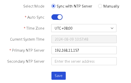
6. Click Save.
Manually set the system time
1. In the navigation pane, select Menu > System > System > System Time Settings.
2. Select Manually, and select the date and time to be used by UniSystem.
Figure 298 Setting the system manually
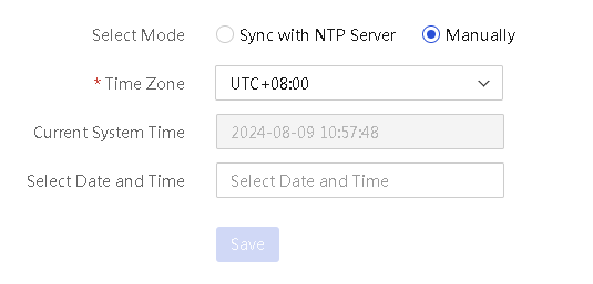
3. View the current time zone. You can select a time zone as needed.
4. Click Save.
Configure a cluster
About this task
This feature is available in version 2.00.17 and later.
This module allows you to create or manage a cluster of AE modules to implement high availability. UniSystem automatically monitors the status of the primary node. When the primary node fails, UniSystem will switch to run on the secondary node, which avoids service interruption caused by the failure of the primary AE module.
Prerequisites
Cluster creation requires data synchronization. For correct data synchronization, make sure the time difference between the primary and secondary nodes is shorter than 10 seconds. For more information about how to set the system time, see "Configure the system time."
If a cluster is created, make sure the following conditions are met:
· Make sure the primary and secondary nodes can reach each other. As a best practice, assign static IP addresses to ports for the primary and secondary nodes to communicate with each other and make sure the ports have the same subnet mask.
· Make sure the primary and secondary nodes each have a unique host name for UniSystem access. Do not set the host name to localhost or a string of all digits.
· Do not configure multiple IP addresses on the same subnet for each network port.
For more information about how to set the host name and the network settings, see "Configure the network settings."
Restrictions and guidelines
· The secondary UniSystem node in the cluster will be stopped during cluster creation.
· During cluster creation, do not power off the AE modules or disconnect the network. Data synchronization will take a long time, please wait till the whole progress finishes.
· During cluster creation, do not perform any other operations on UniSystem of the primary node.
· After the cluster is created, do not edit the host name, network, or system settings of UniSystem.
· UniSystem cannot be reverted from cluster mode to standalone mode.
· The host name of an AE module used in a cluster cannot be localhost or all digits.
· As a best practice, use a static IP address for the port on the primary and secondary node used for communication.
· Cluster creation failure will cause the unavailability of UniSystem. Please try again to create the cluster.
Procedure
1. In the navigation pane, select Menu > System > Cluster
2. Click the Create Cluster link.
3. On the page that opens, configure the following parameters of the cluster to be created.
¡ Secondary Node Address—IP address used by the secondary node to communicate with the primary node. As a best practice, use the IP address of network port vmng.om or the 10-GE network port of the secondary AE module.
¡ UniSystem Virtual IP Address—Virtual IP address for users to access UniSystem after the cluster is created.
¡ iSCSI Virtual IP Address—IP address used to configure the iSCSI service. Make sure the entered iSCSI virtual IP address is on the same network segment as an IP address of the 10-GE network port on the primary AE module.
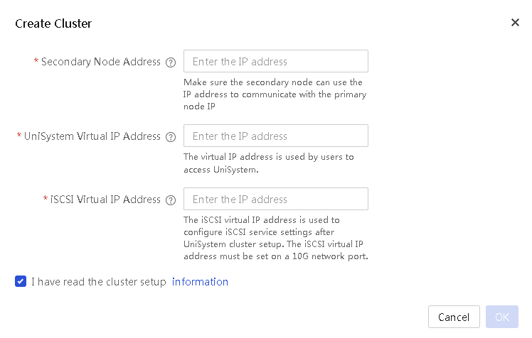
4. Click OK. You can see the progress of the creation from the progress bar. To view detailed information about the cluster creation, click View Log.
5. UniSystem will automatically restart after the cluster is successfully created. Log in to UniSystem by using the virtual IP address of UniSystem.
6. View information about the primary and secondary nodes on the Cluster page.
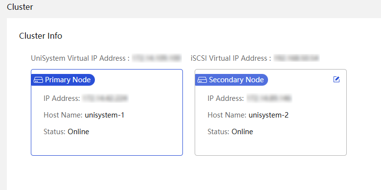
7. Click the Edit
icon ![]() next to the secondary node. In the dialog box that opens, enter the
IP address of the node to replace the current secondary node. Then, click OK. You can see the progress of the replacement from the
progress bar.
next to the secondary node. In the dialog box that opens, enter the
IP address of the node to replace the current secondary node. Then, click OK. You can see the progress of the replacement from the
progress bar.
Maintain and upgrade
Perform this task to back up and restore the UniSystem data and upgrade the UniSystem software.
Back up and restore UniSystem data
About this task
This feature is available in version 2.00.14 and later.
This module allows you to back up and restore the UniSystem data, download system operation logs, and restore the default UniSystem settings.
The UniSystem data that can be backed up or restored includes the device information, component update task information, configuration template or file information, address pool information, and user information. The following data cannot be backed up: Repositories, image files uploaded to the image list, cloned images, diskless boot volumes, listening settings, DHCP settings, and the version update file uploaded on the UniSystem version update page.
After you restore the default settings, the information that can be backed up on the UniSystem server is cleared and the user settings are restored to the default.
Restrictions and guidelines
· Before you restore the UniSystem data or restore the default settings of UniSystem, back up the current UniSystem data.
· To avoid restoration failure, do not perform any operations that might affect the restoration during UniSystem data restoration or default UniSystem setting restoration.
· To ensure that UniSystem operates properly, you must manually reboot UniSystem after you restore the UniSystem data or restore the default settings of UniSystem. In version 2.39 and later, after UniSystem data restoration or default UniSystem setting restoration, UniSystem of the package version will be automatically stopped, and UniSystem on a VM or AE module will be restarted.
· To avoid configuration file verification failure during data restoration, do not make any changes to the backup configuration file.
· A server template or server configuration file becomes invalid after backup or restoration if it contains an image file or repository in the system settings. You must reconfigure the template or file before applying it to a server.
Procedure
1. In the navigation pane, select Menu > System > Maintain and Upgrade. Click the Backup & Restore tab.
Figure 301 Backup & Restore page
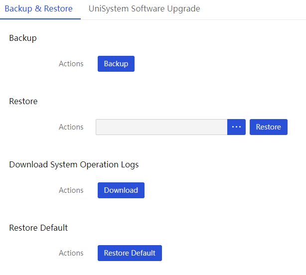
2. To back up the running configuration, click Backup. The system will export the running configuration to a compressed file.
3. To restore the configuration in a configuration file, click … next to Restore, select the target configuration file, and then click Restore.
4. To download UniSystem system operation logs in a compressed file to the local host, click Download.
5. To restore the default settings, click Restore Default. In the dialog box that opens, click OK.
Upgrade UniSystem software
About this task
This feature is available in version 2.39 and later.
This feature allows you to upgrade or downgrade the UniSystem software version. UniSystem software upgrade will not cause UniSystem data loss. However, as a best practice, back up the critical data before upgrading UniSystem.
The UniSystem upgrade interface is available only for UniSystem running on a VM or AE module. UniSystem of the package version does not need installation. To upgrade UniSystem of the package version, replace the new package with the old package.
Restrictions and guidelines
· To ensure that UniSystem can be upgraded normally, first stop the other UniSystem operations in progress before upgrading UniSystem.
· Upgrading UniSystem will log out all logged-in users except the current user. Additionally, other users cannot log in during the UniSystem upgrade process.
· Upgrading UniSystem will interrupt or restart related processes in the system where UniSystem is installed. If these processes are being used, related services might be interrupted.
Procedure (for UniSystem on a VM or AE module)
1. In the navigation pane, select Menu > System > Maintain and Upgrade. Click the UniSystem Software Upgrade tab.
Figure 302 UniSystem Software Upgrade page
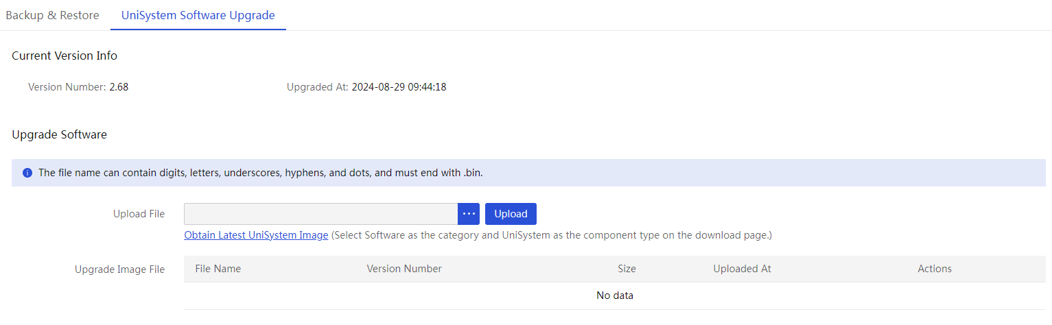
2. (Optional.) Click Obtain Latest UniSystem Image to download the needed UniSystem software upgrade package from the official website.
3. Click the … button for the software upgrade operation, select the UniSystem upgrade package, and click Upload to upload the upgrade package.
4. Click Start Upgrade. In the dialog box that opens, click OK to start upgrading UniSystem.
After the upgrade is finished, UniSystem will automatically restart and return to the login page. After UniSystem is restarted, refresh the page, and log in to use the new UniSystem version.
Procedure (for UniSystem of the package version)
|
|
IMPORTANT: After the upgrade, the port configuration cannot be retained. |
1. Obtain the UniSystem upgrade package from the official website, and then click STOP to stop UniSystem, as shown in Figure 303.
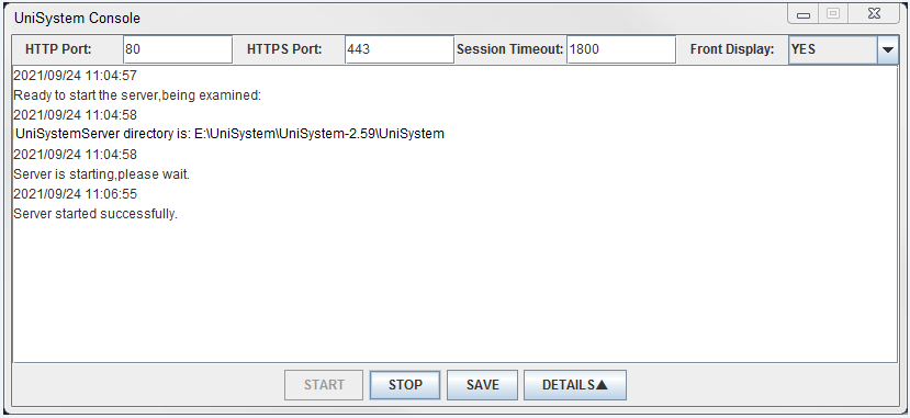
2. Select the new UniSystem upgrade package, decompress the package, and override the original UniSystem directory. Then, choose to replace all files as instructed, as shown in Figure 304.
Figure 304 Replacing all files
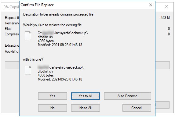
3. Restart UniSystem.
Configure the security tip for login
About this task
This feature is available in version 2.34 and later.
This module allows you to enable and configure the security tip for login.
Procedure
1. In the navigation pane, select Menu > System > Users and Security > Security Tip for Login.
Figure 305 Configuring the security tip for login
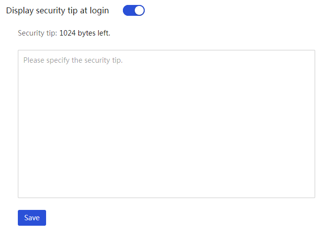
2. Select to enable Display security tip at login.
3. Enter a security tip or leave the security tip field empty.
4. Click Save.
After you save the security tip successfully, you can view the configured security tip on the login page.
Remote control
This feature allows you to enable repair settings to monitor the health status of incorporated servers. When the system detects a server exception, it can trigger a repair task automatically and upload the corresponding SDS logs to iService.
Enable repair settings
Restrictions and guidelines
If the upload method is manual, only manual repair report is supported.
Procedure
1. In the navigation pane, select Menu > System > Remote Control and click the Repair Settings tab.
Figure 306 Repair settings
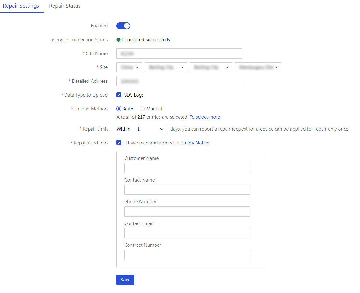
2. Enable repair settings.
3. Enter the site name where the UniSystem server is located.
4. Enter the site information and detailed address where the UniSystem server is located.
5. Select the type of data to be uploaded and the upload method. If you select Auto, perform the following operations:
a. (Optional.) Click To select more. In the dialog box that opens, select the repair data on the corresponding tab.
Figure 307 Selecting the repair data
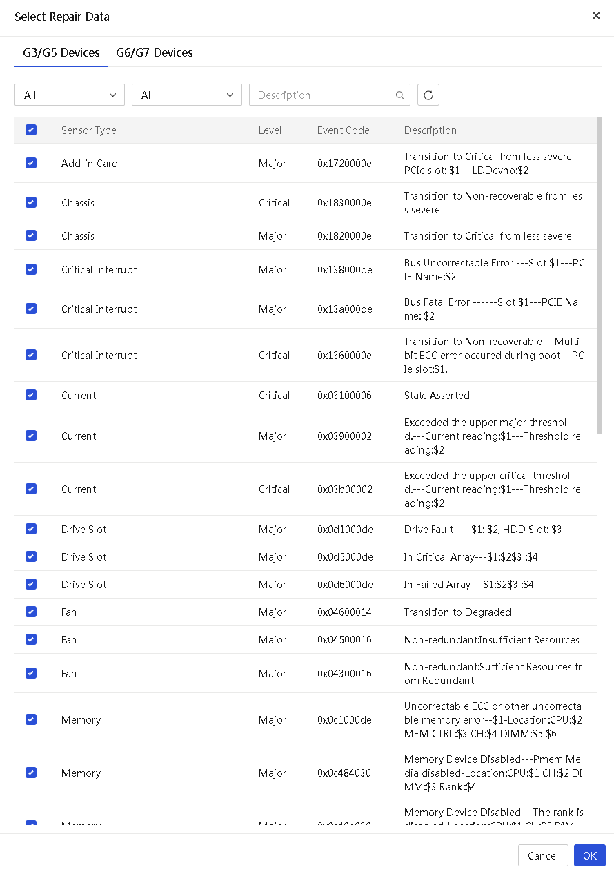
b. Set a limit on the number of repair requests. Options include:
- Unlimited—Does not limit alarms within a day. As long as automatic repair is satisfied, the repair report can be handled promptly.
- 1—Handles all alarms from the past day up to the time of the automatic repair request.
- 2—Handles all alarms from the past two days up to the time of the automatic repair request.
- 3—Handles all alarms from the past three days up to the time of the automatic repair request.
c. Check I have read and agree to the repair service process and fill in the warranty information.
6. Click Save.
View repair status
1. In the navigation pane, select Menu > System > Remote Control and click the Repair Status tab.
Figure 308 Viewing the repair status
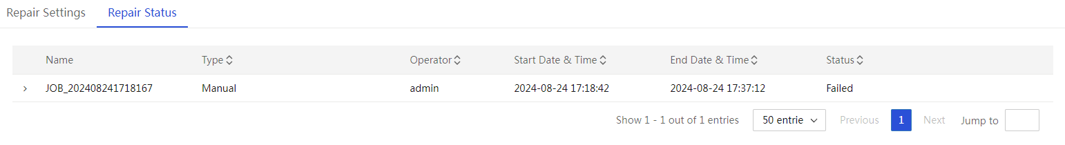
2. To view the repair information about each device in a repair task, click the task name.
Figure 309 Viewing the repair information
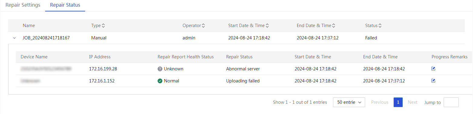
3. To edit the remarks for a repair task, wait for the task to finish and then enter the remarks in the Progress Remarks column.
Figure 310 Editing repair request remarks
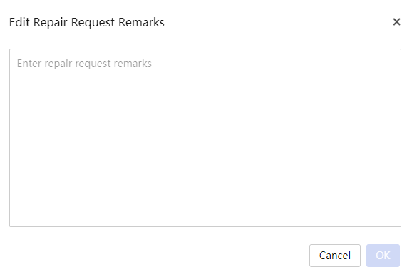
Custom menu
Perform this task to customize the menu items to be displayed on the top navigation bar.
View the current menu and all menu items
Restrictions and guidelines
· The default menu contain all menu items. If you select Default, the Custom Menu page does not display the menu items.
· By default, UniSystem uses the default menu, which displays all menu items in the menu bar.
· If the custom menu in use does not include the Shortcuts item, you cannot remove shortcut items. To remove shortcut items, switch to the default menu, remove the items, and then switch back to the custom menu.
Procedure
1. In the navigation pane, select Menu > System > Custom Menu.
2. View the current menu.
3. To view all the menu items, click Add Menu. The Select Menu Items box displays all the selectable menu items.
Figure 311 Viewing the current menu and all menu items

Create a custom menu
Restrictions and guidelines
· The menu name is a case-sensitive string of 1 to 10 characters and can contain only digits, letters, underscores (_), and hyphens (-). The menu name cannot be Default or any other combination of upper or lowercase letters that spells "default".
· In addition to the default menu, you can create up to 4 custom menus.
· You cannot create two menus with the same name.
· The menu items may be related. When you select a menu item, its related menu items are also selected. However, when you unselect a menu item, only that item is unselected, and its related menu items are not affected.
Procedure
1. In the navigation pane, select Menu > System > Custom Menu.
2. Click Add Menu to create a new custom menu.
3. Enter a menu name that meets the requirement and select the menu items.
Figure 312 Creating a custom menu
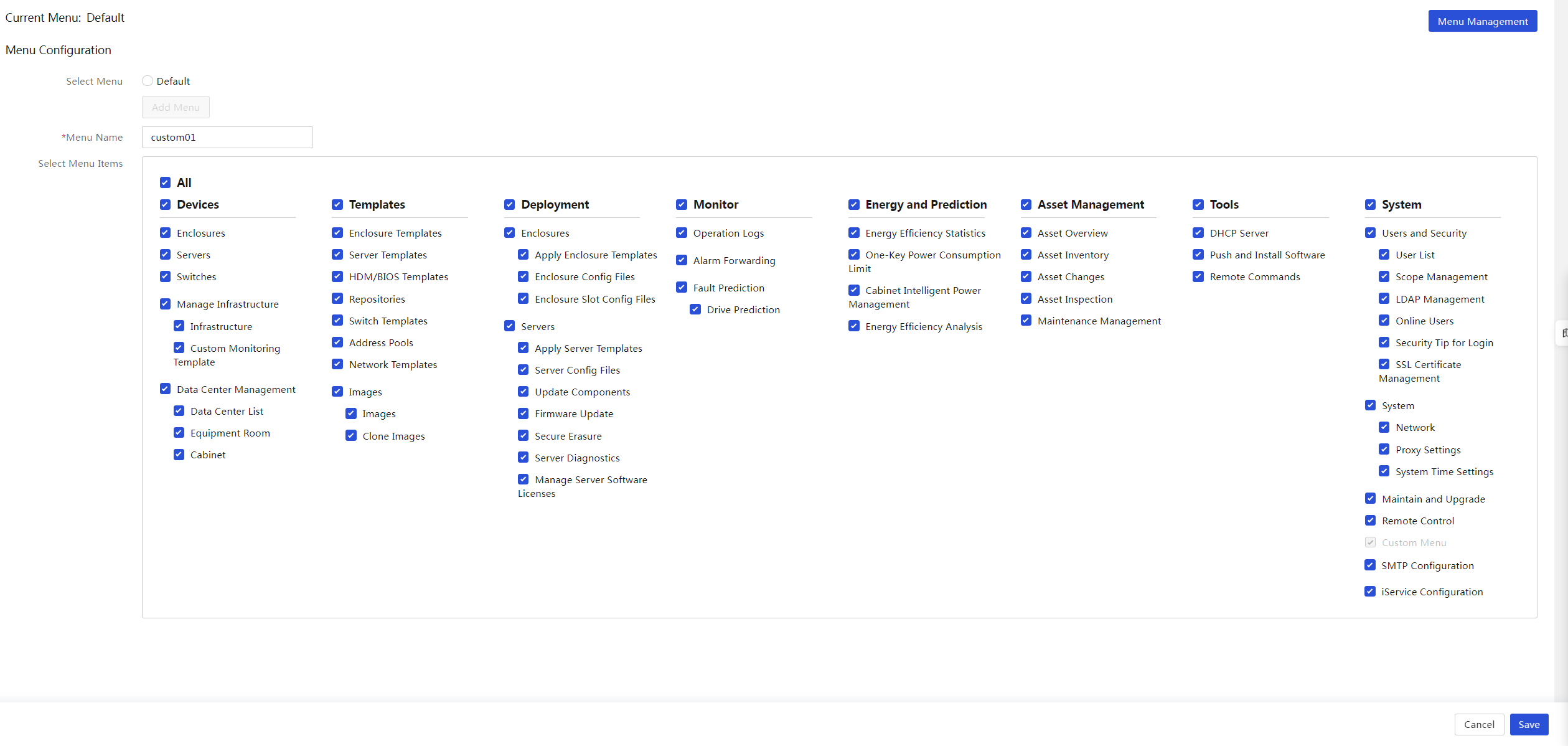
4. Click Save, and then click OK in the dialog box that opens to save the menu. The page will automatically refresh and display the selected menu items in the menu bar.
Edit a custom menu
Restrictions and guidelines
· The menu name is a case-sensitive string of 1 to 10 characters and can contain only digits, letters, underscores (_), and hyphens (-). The menu name cannot be Default or any other combination of upper or lowercase letters that spells "default".
· You cannot create two menus with the same name.
· You cannot edit the default menu.
Procedure
1. In the navigation pane, select Menu > System > Custom Menu.
2. Select a custom menu.
3. Click Edit to edit the custom menu.
Figure 313 Editing a custom menu

4. (Optional.) Enter a menu name that meets the requirement and select the menu items.
5. Click Save, and then click OK in the dialog box that opens to save the menu. The page will automatically refresh and display the selected menu items in the menu bar.
Delete a custom menu
Restrictions and guidelines
· You cannot delete the default menu.
· Deleting the custom menu in use causes the system to switch to the default menu, and the page will be refreshed.
Procedure
1. In the navigation pane, select Menu > System > Custom Menu.
2. Click Menu Management. The page that opens displays all menus.
Figure 314 Deleting a custom menu
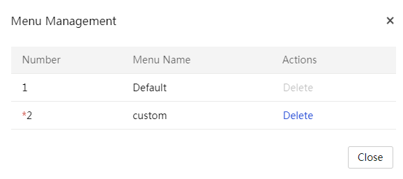
3. Click Delete in the Actions column for the menu to be deleted, and then click OK in the dialog box that opens.
System interfacing
iService configuration
About this task
Use the iService feature to connect to the iService platform to enable synchronization of maintenance information and auto fault reporting, reducing manual intervention and increasing maintenance efficiency.
· Real-time update of maintenance information: Allows UniSystem to obtain real-time updates on device maintenance information, enhancing the automation level of asset management.
· Automatic fault reporting: Enables the system to automatically send a repair request to iService when a device experiences a fault or an alarm. This improves the timeliness of fault processing.
Procedure
1. In the navigation pane, select Menu > System > System Interfacing.
2. Click the iService tab to enter iService configuration page.
Figure 315 iService Configuration
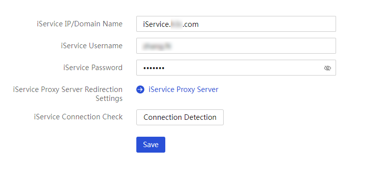
3. Configure iService-related information.
¡ Specify the iService IP address or domain name.
¡ Enter the username registered on the iService official website.
¡ Enter the password for the iService username.
¡ To configure an iService proxy server, click iService Proxy Server, and specify the related information.
Figure 316 Configuring proxy settings

4. Click Connection Detection to test the connectivity between UniSystem and iService.
5. Click Save.
Email notification configuration
About this task
Simple Mail Transfer Protocol (SMTP) allows the system to send information, including alarm and inspection information through email to specific recipients. You can perform this task to specify an SMTP server, as well as the email sender and recipients.
Prerequisites
Obtain the IP address and port number of the SMTP server and make sure the IP address of the UniSystem server can reach the SMTP server.
Procedure
1. In the navigation pane, select Menu > System > System Interfacing.
2. Click the Email tab.
Figure 317 Email notification
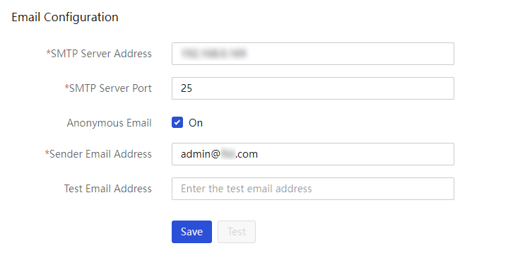
3. Configure the parameters as required:
¡ Enter the IP address and port number of the SMTP server.
¡ Select whether to select Anonymous Email. If you do not select Anonymous Email, you must select an encryption protocol and enter the sender's username, password, and encryption protocol for connecting to the SMTP server.
¡ Enter the sender email address.
4. To test the connectivity to an email address, enter the email address in the Test Email Address field, and then click Test.
5. Click Save.
SMS message notification configuration
UniSystem of the unified O&M version does not support SMS message notification.
About this task
Perform this task to configure SMS notification settings. After you configure and enable this feature, UniSystem will send the received SNMP traps from the managed servers to specific receivers through SMS.
Only Emay is supported in the current software version. For information about the SMS service, contact Emay. For Emay, the SMS service in mainland China is different from the SMS service in Hong Kong SAR, Macao SAR, and Taiwan Province of China and other countries or regions, and the user IDs cannot be used across services. For other functions, contact the Emay customer service.
Procedure
1. In the navigation pane, select Menu > System > System Interfacing.
2. Click the SMS Message tab.
Figure 318 SMS message notification
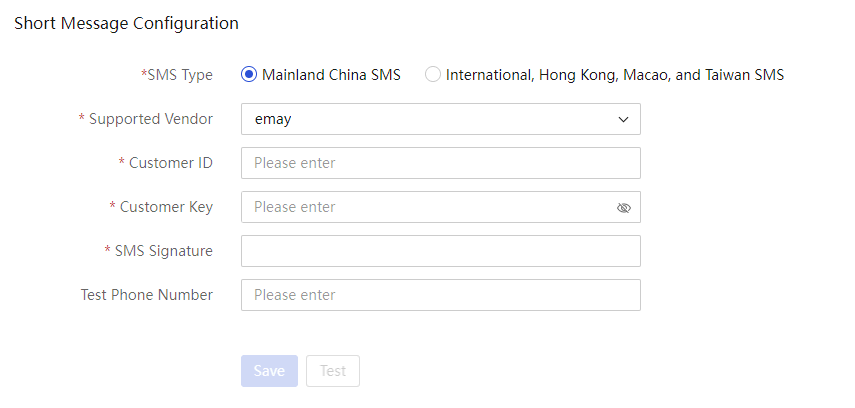
3. Configure the parameters as required.
¡ Select an SMS type. Options include Mainland China SMS and International, Hong Kong, Macao, and Taiwan SMS.
¡ Select a supported vendor. Only Emay is supported in the current software version.
¡ Enter the customer ID (App ID obtained from Emay).
¡ Enter the customer key (secret key obtained from Emay).
¡ Enter the SMS signature. The signature is the content contained in the square brackets at the beginning of a text message. The system can send text messages only after the SMS signature is added.
4. (Optional.) Enter a test phone number. To test the connectivity to the test phone number, click Test. For a phone number registered in Hong Kong SAR, Macao SAR, and Taiwan Province of China or another country or region, enter the phone number in the format of 00+international area code+phone number.
5. Click Save.
Restrictions and guidelines
To use this feature, make sure you can access the Internet over HTTP or HTTPS. Configure DNS settings or a proxy server as needed. For more information, see "Configure the network settingsD:\ICC\1698583425230651392\27\EN\3739\UniSystem Online Help.docx - _Topic_14961_20230906105713_title" and "Configuring proxy settingsD:\ICC\1698583425230651392\27\EN\3739\UniSystem Online Help.docx - _Topic_14968_20230906100563_title."
Voice message configuration
UniSystem of the unified O&M version does not support voice message notification.
This feature is supported in 2.34 and later versions.
About this task
Perform this task to configure voice notification settings. After you configure and enable this feature, UniSystem will send the received SNMP traps from the managed servers to specific receivers through voice messages.
Procedure
1. In the navigation pane, select Menu > System > System Interfacing.
2. Click the Voice Message tab.
Figure 319 Voice message notification
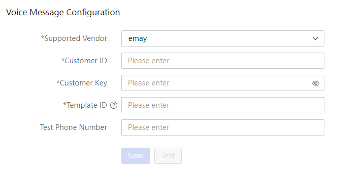
3. Configure the parameters as required.
¡ Select a supported vendor. Only Emay is supported in the current software version.
¡ Enter the customer ID (App ID obtained from Emay).
¡ Enter the customer key (secret key obtained from Emay).
¡ Enter the template ID obtained from Emay.
4. To test the connectivity to a phone number, enter the phone number and click Test. Only phone numbers registered in mainland China are supported.
5. Click Save.
Restrictions and guidelines
· To use this feature, make sure you can access the Internet over HTTP or HTTPS. Configure DNS settings or a proxy server as needed. For more information, see "Configure the network settingsD:\ICC\1698583425230651392\27\EN\3739\UniSystem Online Help.docx - _Topic_14961_20230906105713_title" and "Configuring proxy settingsD:\ICC\1698583425230651392\27\EN\3739\UniSystem Online Help.docx - _Topic_14968_20230906100563_title."
· To send voice messages successfully, notify Emay of the voice message template before using this feature. For more information, contact the Emay customer service.
· If you edit the message template, notify Emay of the new template for Emay to update the template simultaneously. Then, you can obtain a new template ID from Emay.
WeCom notification configuration
UniSystem of the unified O&M version does not support WeCom notification.
This feature is supported in 2.34 and later versions.
About this task
Perform this task to configure WeCom notification. After you configure and enable this feature, UniSystem will send the received SNMP traps from the managed servers to specific receivers through WeCom messages.
Procedure
1. In the navigation pane, select Menu > System > System Interfacing.
2. Click the WeCom tab.
Figure 320 WeCom notification
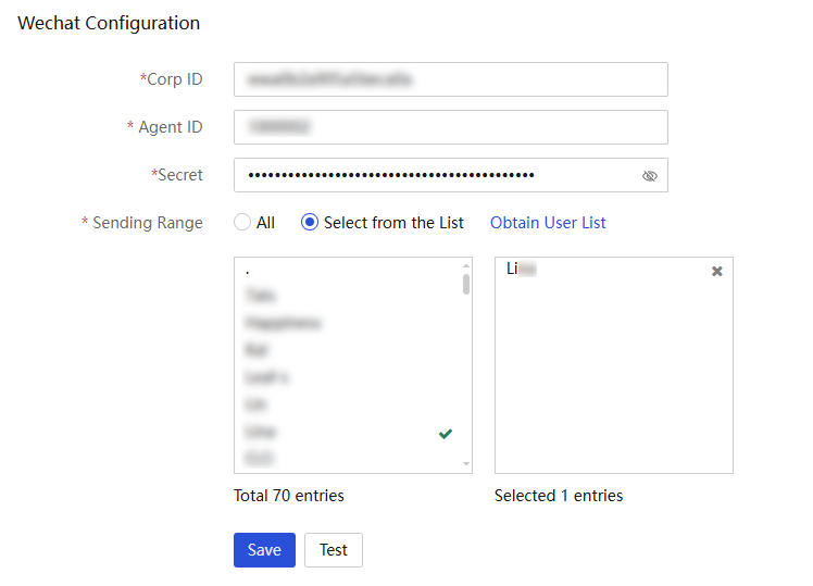
3. Configure the parameters as required and click Save.
4. (Optional.) Click Test to send a test alarm message to the specified WeCom application.
Parameters
· Corp ID: Corporation ID on WeCom. Each corporation has a unique corporation ID. For the administrator to obtain the corporation ID, access the management Web interface, and access the My Company > Company information page.
· Agent ID: Agent ID on WeCom. Each application has a unique agent ID. For the administrator to obtain the agent ID, access the management Web interface, and access the App Management > Apps page.
· Secret: A key to ensure data security. Each application has a unique access key. To ensure the security of the data, the secret key cannot be leaked. To obtain the secret, access the management Web interface, access the App Management > Apps page, and click the corresponding application in the Self-built section.
· Sending Range: WeCom users that can obtain alarm messages. Click Obtain User List to obtain the available user list for notification from the WeCom backend, and then further select users that can obtain alarm messages as needed.
Restrictions and guidelines
· Only the WeCom administrator can obtain the WeCom parameters. To obtain WeCom parameters, see the related WeCom document at https://open.work.weixin.qq.com/api/doc/90000/90135/90665.
· To use this feature, make sure you can access the Internet over HTTP or HTTPS. Configure DNS settings or a proxy server as needed. For more information, see "Configure the network settingsD:\ICC\1698583425230651392\27\EN\3739\UniSystem Online Help.docx - _Topic_14961_20230906105713_title" and "Configuring proxy settingsD:\ICC\1698583425230651392\27\EN\3739\UniSystem Online Help.docx - _Topic_14968_20230906100563_title."
WhatsApp notification configuration
About this task
Perform this task to configure WhatsApp notification. After you configure and enable this feature, UniSystem will send the SNMP traps from the managed servers to WhatsApp.
Procedure
1. In the navigation pane, select Menu > System > System Interfacing.
2. Click the WhatsApp tab.
Figure 321 WhatsApp notification
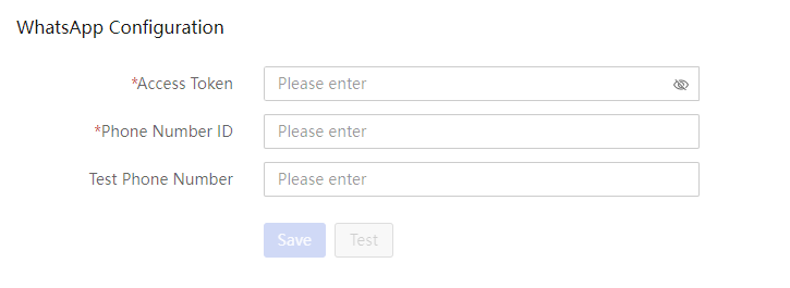
3. Configure the parameters as required and click Save.
4. (Optional.) Enter the test phone number, and then click Test to send a test alarm message to the specified WhatsApp application.
Parameters
· Access Token: An access token is a security credential used for authorizing access to the WhatsApp Business API. It is a long-term valid token used for verifying and authorizing API requests. By using an access token, API clients can send requests to WhatsApp to perform various operations.
· Phone Number ID: In the WhatsApp Business API, each registered phone number is assigned a unique phone number ID, to ensure unique identification and recognition in API requests and operations.
· Test Phone Number: Enter an international phone number for receiving notifications. The international phone number does not require a plus sign (+), but must include the country/region code.
Restrictions and guidelines
· To obtain the Access Token, Phone Number ID, and to processes related to WhatsApp Business API configuration, contact Technical Support.
· To use this feature, make sure you can access the Internet over HTTP or HTTPS. Configure DNS settings or a proxy server as needed. For more information, see "Configure the network settings" and "Configuring proxy settings."
Webhook notification configuration
UniSystem of the unified O&M version does not support Webhook notification.
This feature is supported in 2.65 and later versions.
About this task
Perform this task to configure group robot notification for WeCom groups, DingTalk groups, Telegram groups. After you configure and enable this feature, UniSystem will send the received SNMP traps from the managed servers to specific groups.
Prerequisites
Each group chat robot has a unique Webhook address. You must obtain the following information before configuring this feature:
· For a WeCom group, obtain the Webhook address for the WeCom chat robot.
· For a DingTalk group, obtain the Webhook address and signature for the DingTalk chat robot.
· For a Telegram group, obtain the Webhook address and signature for the Telegram chat robot.
Procedure
1. In the navigation pane, select Menu > System > System Interfacing.
2. Click the Webhook tab.
Figure 322 Wehook notification
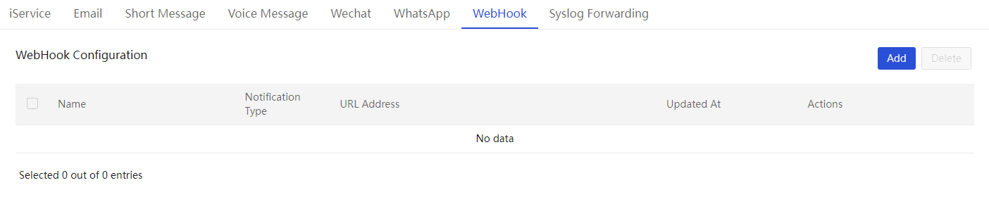
3. Click Add. In the dialog box that opens, configure webhook settings as required.
a. Enter the name of the webhook configuration.
b. Select the notification type. Options include WeCom, DingTalk, and Telegram.
c. Specify the Webhook URL address for the WeCom group robot, DingTalk group robot, or Telegram group robot.
d. Enter the sign information. This field is required if you select the DingTalk notification type.
e. Click Test to send a test alarm message to the specified group chat application.
f. Click OK.
4. To edit or delete a webhook entry, click Edit or Delete in the Actions column for that setting.
5. To delete one or multiple webhook entries, select the target webhook entries, and then click Delete in the upper right corner of the webhook entry list.
Restrictions and guidelines
· To obtain the Webhook address for WeCom and DingTalk, access the group member list.
· To obtain the Webhook address for Telegram:
a. Open the Telegram application and access BotFather.
b. Execute commands to create a Telegram bot. After a successful creation, a token for the current bot to use the API is returned.
c. Repalce the token with the <token> argument in https://api.telegram.org/bot<token>/sendMessage to obtain the URL address for Telegram.
· To use this feature, make sure you can access the Internet over HTTP or HTTPS. Configure DNS settings or a proxy server as needed. For more information, see "Configure the network settings" and "Configuring proxy settings."
Syslog forwarding configuration
About this task
Perform this task to configure UniSystem as the client to send syslog messages.
Procedure
1. In the navigation pane, select Menu > System > System Interfacing.
2. Click the Syslog Forwarding tab.
Figure 323 Syslog Forwarding
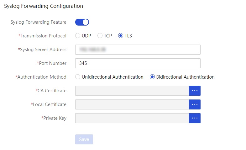
3. Configure the parameters as required.
a. Enable syslog forwarding.
b. Select UDP, TCP, or TLS as the transmission protocol.
c. Specify the syslog server address and port. The port range is 1 to 65535. The default port number of UDP and TCP is 514, and the default port number of TLS is 6514.
d. If you select TLS,
select an authentication method. Options include Unidirectional
Authentication and Bidirectional Authentication.
If you select Bidirectional Authentication, click ![]() in
the CA Certificate field to upload a CA certificate
file, a local certificate file, and a private key file.
in
the CA Certificate field to upload a CA certificate
file, a local certificate file, and a private key file.
4. Click Save.
Scope management
Scope management divides resources into different scopes based on dimensions such as departments and regions. It allows assigning roles and permissions to different users or user groups, enabling users to only access and manage resources they are authorized for, achieving fine-grained management and security isolation of resources.
Resources include: enclosures, servers, switches, infrastructure, data centers, enclosure configuration templates, server configuration templates, switch configuration templates, and scopes.
View scopes
Procedure
1. In the navigation pane, select Menu > System > Users and Security > Scope Management.
2. View scope information.
Figure 324 Scopes
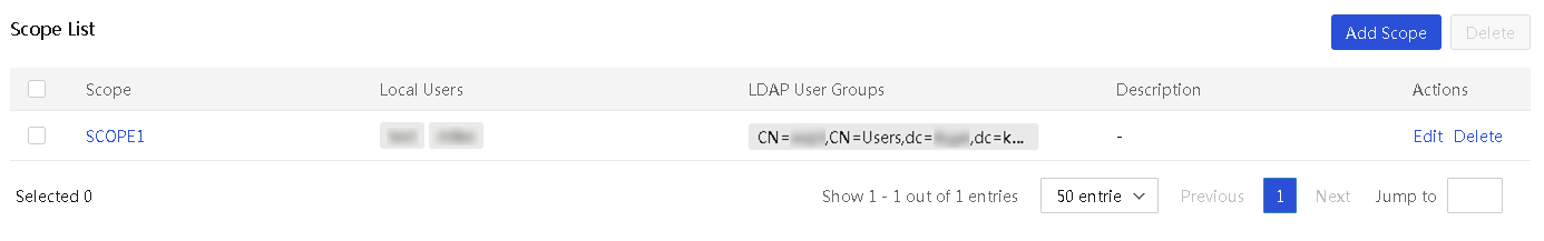
3. To view scope details, click the name link.
Figure 325 Scope details
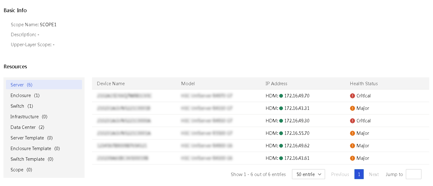
Parameters
· Scope list
¡ Scope: Name of the scope.
¡ Local Users: Local users associated with the scope.
¡ LDAP User Groups: LDAP user groups associated with the scope.
¡ Description: Description of the scope.
· Scope details
¡ Scope Name: Name of the scope.
¡ Description: Description of the scope.
¡ Upper-Layer Scope: Upper-layer scope of the scope.
¡ Resources: Resources managed by the scope.
Add a scope
Procedure
1. In the navigation pane, select Menu > System > Users and Security > Scope Management.
2. Click Add Scope.
Figure 326 Adding a scope
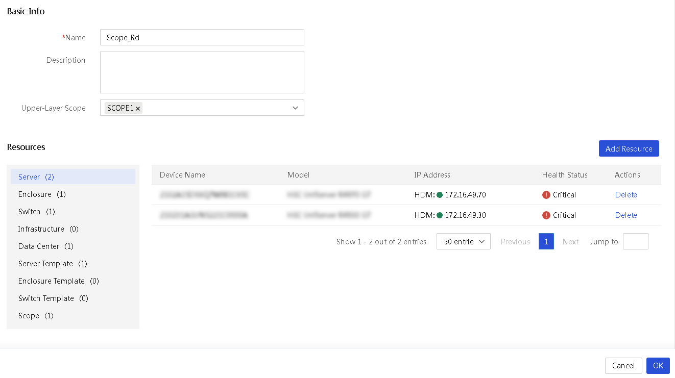
3. Configure the scope as follows:
¡ Enter the scope name.
¡ (Optional.) Enter the scope description.
¡ (Optional.) Select the upper-layer scope.
4. Click Add Resources and perform the following tasks.
a. Select the resource type.
b. Select the resources to be associated with the scope. You can use the search box to filter resources.
c. Click OK.
5. Click OK.
Parameters
· Name: Enter the name of the scope.
· Description: Enter the description of the scope.
· Upper-Layer Scope: Select the upper-layer scope. Users associated with the upper-layer scope can management the scope.
· Resources: Select resources to be associated with the scope. Options include enclosure, server, switch, infrastructure, data center, enclosure configuration template, server configuration template, switch configuration template, and scope.
Edit a scope
1. In the navigation pane, select Menu > System > Users and Security > Scope Management.
2. Click Edit for the target scope and edit the scope as needed.
3. Click OK.
Delete scopes
Restrictions and guidelines
You cannot delete a scope associated with a user or user group.
Procedure
1. In the navigation pane, select Menu > System > Users and Security > Scope Management.
2. Perform either of the following tasks:
¡ To delete multiple scopes, select the target scopes, and then click Delete.
¡ To delete a specific scope, click Delete for the scope.
3. In the confirmation dialog box that opens, click OK.
Manage LDAP
UniSystem can work with an LDAP server to provide quick access to LDAP users on the server.
You can add LDAP servers to UniSystem and then add LDAP user groups on the LDAP servers to UniSystem. Member users in the LDAP user groups can then log in to UniSystem directly with their credentials stored in the LDAP server.
View LDAP server information and test connectivity to a server
1. In the navigation pane, select Menu > System > Users and Security > LDAP Management.
The LDAP Settings tab displays information about the LDAP servers configured in the system, each on a separate card.
Figure 327 LDAP settings tab
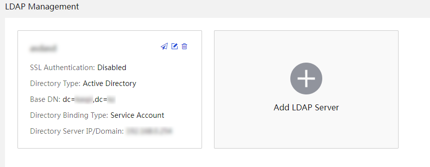
2. (Optional.) To test connectivity to an LDAP
server, click the ![]() icon in the top right corner of the LDAP server card. For an LDAP
server that uses the User Account directory binding
type, you will be prompted to enter the username and password for connectivity
test.
icon in the top right corner of the LDAP server card. For an LDAP
server that uses the User Account directory binding
type, you will be prompted to enter the username and password for connectivity
test.
Add an LDAP server
Perform this task to add an LDAP server to UniSystem. UniSystem supports a maximum of 100 LDAP servers.
Procedure
1. In the navigation pane, select Menu > System > Users and Security > LDAP Management.
2. Click Add LDAP Server.
3. In the Add LDAP Server dialog box that opens, configure the LDAP server parameters.
Figure 328 Add LDAP server dialog box

4. Click OK.
Edit an LDAP server
1. In the navigation pane, select Menu > System > Users and Security > LDAP Management.
2. Click the Edit
icon ![]() in the Actions column for the target
LDAP server.
in the Actions column for the target
LDAP server.
3. In the Edit LDAP Server dialog box that opens, edit the LDAP server parameters and click OK.
Delete an LDAP server
1. In the navigation pane, select Menu > System > Users and Security > LDAP Management.
2. Click the Delete
icon ![]() in the Actions column for the target
LDAP server.
in the Actions column for the target
LDAP server.
3. In the confirmation dialog box that opens, click OK.
SSL certificate management
Secure Sockets Layer (SSL) is a protocol for encrypting network communication, used to ensure the security and integrity of data transmission over the Internet. An SSL certificate is a digital certificate that qualifies the identity of a website in the SSL protocol. An SSL certificate uses encryption algorithms and the digital signature technology to ensure the authenticity and trustworthiness of the identity of a website. It ensures that data remains secure and untampered during transmission.
After you upload a custom SSL certificate, access the website through HTTPS to enhance system security.
UniSystem SSL certificate management provides the following features:
· Self-signed certificate: By default, UniSystem supports HTTPS access using a self-signed SSL certificate.
· Certificate upload: Users can upload custom SSL certificates. The system will use the uploaded certificate for HTTPS access, which enhances the security and flexibility of the system.
· If a custom certificate expires, UniSystem automatically detects the expiration state at startup and revert to using the default certificate provided. This ensures secure communication under any circumstances.
View SSL certificate information
About this task
Perform this task to view information about the current certificate used by UniSystem. By default, UniSystem uses the self-signed certificate.
Procedure
1. In the navigation pane, select Menu > System > Users and Security > SSL Certificate Management.
2. View the detailed information of the current SSL certificate.
Figure 329 SSL certificate management
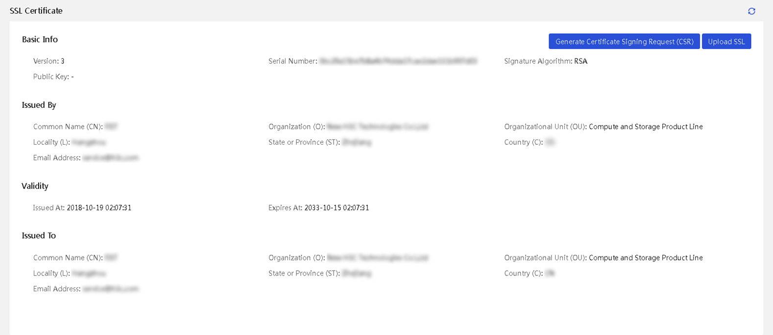
Parameters
· Basic Info: Basic information of the current SSL certificate.
¡ Version: Version of the SSL certificate.
¡ Serial Number: Serial number allocated to the certificate by the Certificate Authority (CA).
¡ Signature Algorithm: Encryption algorithm used by the SSL certificate for signing.
¡ Public Key: Public key information.
· Issued By: Information about the CA that issued the SSL certificate.
· Validity: Validity period of the SSL certificate.
¡ Issued At: First day the certificate becomes effective.
¡ Expires At: Expiry date of the certificate.
· Issued To: Entity to which the certificate was issued.
Upload a custom certificate
About this task
UniSystem supports uploading more trusted custom SSL certificates to provide higher security and trustworthiness.
The process for uploading a custom certificate in UniSystem is as follows:
1. Generate a certificate signing request: Generate a certificate signing request (CSR) in UniSystem and download the request.
2. Submit the CSR to the corporate CA: Submit the generated CSR to the corporate CA for signing and obtain the certificate chain file.
3. Upload the custom certificate: Upload the certificate chain to UniSystem. After a restart, use the uploaded certificate to access UniSystem through HTTPS.
Restrictions and guidelines
· After your custom SSL certificate expires, re-upload the certificate as soon as possible to ensure its validity.
· If UniSystem detects an expired certificate upon startup, it will use the built-in default certificate.
Procedure
1. In the navigation pane, select Menu > System > Users and Security > SSL Certificate Management.
Figure 330 SSL certificate management

2. Generate a CSR.
a. Click Generate Certificate Signing Request (CSR).
b. Configure CSR generation-related information.
c. Click OK to generate a CSR and download it.
|
|
NOTE: Before uploading an SSL certificate, you must first upload the CSR to your corporate CA and complete the signature process to obtain a certificate chain file signed by the CA. |
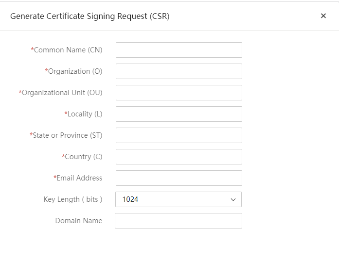
3. Upload the SSL certificate.
a. Click Upload SSL.
b. Click the ![]() icon, and select
the SSL certificate chain file. Supported file formats include PEM, DER, and
PKCS7.
icon, and select
the SSL certificate chain file. Supported file formats include PEM, DER, and
PKCS7.
c. Click OK. The certificate takes effect after UniSystem restarts.

Parameters
· Common Name (CN): Full domain name of the server owner.
¡ The string is in the range of 1 to 64 characters.
¡ The string cannot contain only digits.
¡ Only letters, Russian characters, digits, spaces, underscores (_), hyphens (-), and dots (.) are supported.
· Organization (O): Name of the company or organization that owns this server.
¡ The string is in the range of 1 to 64 characters.
¡ The string cannot contain only digits.
¡ Only letters, Russian characters, digits, spaces, underscores (_), hyphens (-), dots (.), and commas (,) are supported.
· Organization Unit (OU): Unit of the company or organization that owns this server.
¡ The string is in the range of 1 to 64 characters.
¡ The string cannot contain only digits.
¡ Only letters, Russian characters, digits, spaces, underscores (_), hyphens (-), and dots (.) are supported.
· Locality (L): City or county where the company or organization that owns this server is located.
¡ The string is in the range of 1 to 128 characters.
¡ The string cannot contain only digits.
¡ Only letters, Russian characters, digits, spaces, underscores (_), hyphens (-), and dots (.) are supported.
· State or Province (ST): Province, municipality, or autonomous region where the company or organization that owns this server is located.
¡ The string is in the range of 1 to 128 characters.
¡ The string cannot contain only digits.
¡ Only letters, Russian characters, digits, spaces, underscores (_), hyphens (-), and dots (.) are supported.
· Country (C): Country or region where the company or organization that owns this server is located. The country or region code can contain only two letters.
· Email Address: Email address of the company or organization that owns this server.
· Key Length: Length of the certificate key.
· Domain Name: An SSL certificate can include a domain name or wildcard domain name to meet the security requirements of different websites. The domain name is part of the SSL certificate, ensuring that the certificate applies only to the specified domain, providing security protection for that domain.
Acronyms
|
Term |
Definition |
|
BIOS |
Basic Input Output System |
|
CPLD |
Complex Programmable Logic Device |
|
CPU |
Central Processing Unit |
|
DHCP |
Dynamic Host Configuration Protocol |
|
FIST SMS |
FIST System Management Service, is a software package used with UniSystem for managing servers |
|
GUI |
Graphical User Interface |
|
HBA |
Host Bus Adapter |
|
HDM |
Hardware Device Management |
|
IPMI |
Intelligent Platform Management Interface |
|
OS |
Operating System |
|
PXE |
Preboot Execute Environment |
|
RAID |
Redundant Arrays of Independent Disks |
|
SDS |
|
|
UEFI |
Unified Extensible Firmware Interface |
