- Table of Contents
- Related Documents
-
01-text
1 Product models and technical specifications
Technical specifications for non-PoE switch models
Technical specifications for PoE switch models
180 W power supply (PSR180-12D-B)
10/100/1000BASE-T autosensing Ethernet port
10/100/1000BASE-T Ethernet port LED
Cloudnet management status LED
1 Product models and technical specifications
Product models
Table1-1 describes the S5135S switch series models.
Table1-1 S5135S switch series models
|
Model |
Product code (PID) |
|
|
Non-PoE switch models |
S5135S-8T4S-EI-Q |
LS-5135S-8T4S-EI-Q |
|
S5135S-8T4XS-EI-Q |
LS-5135S-8T4XS-EI-Q |
|
|
S5135S-10T2S2X-EI-Q |
LS-5135S-10T2S2X-EI-Q |
|
|
S5135S-16T4S-EI |
LS-5135S-16T4S-EI |
|
|
S5135S-16T4X-EI-Q |
LS-5135S-16T4X-EI-Q |
|
|
S5135S-24S8T4X-EI |
LS-5135S-24S8T4X-EI |
|
|
S5135S-24T4S-EI-Q |
LS-5135S-24T4S-EI-Q |
|
|
S5135S-24T4X-EI-Q |
LS-5135S-24T4X-EI-Q |
|
|
S5135S-48S2T4X-EI |
LS-5135S-48S2T4X-EI |
|
|
S5135S-48ST4X-EI |
LS-5135S-48ST4X-EI |
|
|
S5135S-48T4S-EI-Q |
LS-5135S-48T4S-EI-Q |
|
|
S5135S-48T4X-EI-Q |
LS-5135S-48T4X-EI-Q |
|
|
PoE switch models |
S5135S-8FP4S-EI-Q |
LS-5135S-8FP4S-EI-Q |
|
S5135S-8FP4XS-EI-Q |
LS-5135S-8FP4XS-EI-Q |
|
|
S5135S-16FP4S-EI |
LS-5135S-16FP4S-EI |
|
|
S5135S-16FP4X-EI |
LS-5135S-16FP4X-EI |
|
|
S5135S-24FP4S4X-EI |
LS-5135S-24FP4S4X-EI |
|
|
S5135S-24FP4T4S-EI |
LS-5135S-24FP4T4S-EI |
|
|
S5135S-24P4S-EI |
LS-5135S-24P4S-EI |
|
|
S5135S-24P4X-EI |
LS-5135S-24P4X-EI |
|
|
S5135S-48FP4S-EI |
LS-5135S-48FP4S-EI |
|
|
S5135S-48FP4X-EI |
LS-5135S-48FP4X-EI |
|
|
S5135S-48P4S-EI |
LS-5135S-48P4S-EI |
|
|
S5135S-48P4X-EI |
LS-5135S-48P4X-EI |
|
|
|
NOTE: · To obtain the purchase information, see the product data sheet at https://www.h3c.com/en/Products_and_Solutions/InterConnect/Switches/ and pay attention to the switch product lifecycle management announcement at https://www.h3c.com/en/Support/Policy_Dynamics/Management_Strategy/Products_End_of_Life_Announcement/Switches/. · For information about product and software compatibility, see the release notes. |
Technical specifications for non-PoE switch models
Table1-2 Technical specifications for non-PoE switch models (1)
|
Item |
S5135S-8T4S-EI-Q |
S5135S-8T4XS-EI-Q |
S5135S-10T2S2X-EI-Q |
S5135S-16T4S-EI |
S5135S-16T4X-EI-Q |
|
Physical specifications |
|||||
|
Dimensions (H × W × D, without package materials) |
44 × 266 × 161 mm (1.73 × 10.47 × 6.34 in) |
44 × 266 × 161 mm (1.73 × 10.47 × 6.34 in) |
44 × 266 × 161 mm (1.73 × 10.47 × 6.34 in) |
44 × 330 × 230 mm (1.73 × 12.99 × 9.06 in) |
44 × 440 × 160 mm (1.73 × 17.32 × 6.30 in) |
|
Dimensions (H × W × D, with package materials) |
85 × 368 × 275 mm (3.35 × 14.49 × 10.83 in) |
85 × 368 × 275 mm (3.35 × 14.49 × 10.83 in) |
85 × 368 × 275 mm (3.35 × 14.49 × 10.83 in) |
90 × 425 × 365 mm (3.54 × 16.73 × 14.37 in) |
86 × 540 × 280 mm (3.39 × 21.26 × 11.02 in) |
|
Weight |
≤ 1.1 kg (2.43 lb) |
≤ 1.1 kg (2.43 lb) |
≤ 1.2 kg (2.65 lb) |
≤ 2.0 kg (4.41 lb) |
≤ 1.8 kg (3.97 lb) |
|
Technical specifications |
|||||
|
Memory (RAM) |
1 GB |
||||
|
Flash |
512 MB |
||||
|
Port types and quantity |
|||||
|
Console port |
1 × serial console port |
||||
|
10/100/1000BASE-T autosensing Ethernet port |
8 |
8 |
10 (The two highest-numbered 10/100/1000BASE-T autosensing Ethernet ports form combo interfaces with their corresponding SFP ports, respectively) |
16 |
16 |
|
SFP port |
4 |
2 |
2 (Each and its corresponding 10/100/1000BASE-T autosensing Ethernet port form a combo interface.) |
4 |
N/A |
|
SFP+ port |
N/A |
2 |
2 |
N/A |
4 |
|
Power supply specifications |
|||||
|
Power input |
AC input |
||||
|
Power supply specifications |
· Rated voltage range: 100 VAC to 240 VAC @ 50 Hz or 60 Hz · Max voltage range: 90 VAC to 264 VAC @ 47 Hz to 63 Hz |
||||
|
Melting current of power supply fuse |
3.15 A/250 V |
3.15 A/250 V |
2 A/250 V |
2 A/250 V |
10 A/250 V |
|
Power consumption |
|||||
|
Power consumption (static) Data collection standard: no load |
5 W |
5 W |
5 W |
7 W |
6 W |
|
Power consumption (with typical configuration) Data collection standard: fully configured with DAC cables or twisted pair cables, 30% loaded |
8 W |
8 W |
10 W |
13 W |
13 W |
|
Power consumption (fully configured) Data collection standard: fully configured with transceiver modules or twisted pair cables, 100% loaded |
11 W |
16 W |
16 W |
19 W |
17 W |
|
Thermal consumption |
|||||
|
Static thermal consumption Data collection standard: no load |
15 BTU/hr |
15 BTU/hr |
18 BTU/hr |
21 BTU/hr |
20 BTU/hr |
|
Typical thermal consumption Data collection standard: fully configured with DAC cables or twisted pair cables, 30% loaded |
28 BTU/hr |
28 BTU/hr |
35 BTU/hr |
42 BTU/hr |
43 BTU/hr |
|
Maximum thermal consumption Data collection standard: fully configured with transceiver modules or twisted pair cables, 100% loaded |
37 BTU/hr |
53 BTU/hr |
55 BTU/hr |
63 BTU/hr |
57 BTU/hr |
|
Heat dissipation |
|||||
|
Heat dissipation method |
Fanless, passive cooling |
Fanless, passive cooling |
Fanless, passive cooling |
Fanless, passive cooling |
Fanless, passive cooling |
|
Mean Time Between Failure (MTBF) (Year) |
141.230741 |
141.230741 |
136.689728 |
141.230741 |
145.53 |
|
Mean Time Between Failure (MTBF) (Hour) |
1237181.29116 |
1237181.29116 |
1197402.01728 |
1237181.29116 |
1274860 |
|
Mean time to repair (MTTR) (Hour) |
1 |
||||
|
Availability |
99.999919% |
99.999919% |
99.999916% |
99.999919% |
99.9999% |
|
Environment specifications |
|||||
|
Altitude |
5000 m (16404.20 ft) |
||||
|
Operating temperature |
–5°C to +45°C (23°F to 113°F) Note: The maximum acceptable temperature decreases by 0.33°C (32.59°F) for every 100 m (328.08 ft) increase in altitude from 0 m (0 ft). |
||||
|
Storage temperature |
–40°C to +70°C (–40°F to +158°F) |
||||
|
Relative humidity |
5% RH to 95% RH, noncondensing |
||||
|
Product compliance |
|||||
|
Product compliance |
· Safety standards · EMC standards · Environmental protection and eco-friendly standards |
||||
Table1-3 Technical specifications for non-PoE switch models (2)
|
Item |
S5135S-24T4S-EI-Q |
S5135S-24T4X-EI-Q |
S5135S-48T4S-EI-Q |
S5135S-48T4X-EI-Q |
|
Physical specifications |
||||
|
Dimensions (H × W × D, without package materials) |
44 × 440 × 160 mm (1.73 × 17.32 × 6.30 in) |
44 × 440 × 160 mm (1.73 × 17.32 × 6.30 in) |
44 × 440 × 260 mm (1.73 × 17.32 × 10.24 in) |
44 × 440 × 260 mm (1.73 × 17.32 × 10.24 in) |
|
Dimensions (H × W × D, with package materials) |
86 × 540 × 280 mm (3.39 × 21.26 × 11.02 in) |
86 × 540 × 280 mm (3.39 × 21.26 × 11.02 in) |
125 × 550 × 380 mm (4.92 × 21.65 × 14.96 in) |
125 × 550 × 380 mm (4.92 × 21.65 × 14.96 in) |
|
Weight |
≤ 2 kg (4.41 lb) |
≤ 2 kg (4.41 lb) |
≤ 3.6 kg (7.94 lb) |
≤ 3.6 kg (7.94 lb) |
|
Technical specifications |
||||
|
Memory (RAM) |
1 GB |
|||
|
Flash |
512 MB |
|||
|
Port types and quantity |
||||
|
Console port |
1 × serial console port |
|||
|
10/100/1000BASE-T autosensing Ethernet port |
24 |
24 |
48 |
48 |
|
SFP port |
4 |
N/A |
4 |
N/A |
|
SFP+ port |
N/A |
4 |
N/A |
4 |
|
Power supply specifications |
||||
|
Power input |
AC input |
|||
|
Power supply specifications |
· Rated voltage range: 100 VAC to 240 VAC @ 50 Hz or 60 Hz · Max voltage range: 90 VAC to 264 VAC @ 47 Hz to 63 Hz |
|||
|
Melting current of power supply fuse |
10 A/250 V |
10 A/250 V |
3.15 A/250 V |
3.15 A/250 V |
|
Power consumption |
||||
|
Power consumption (static) Data collection standard: no load |
6 W |
6 W |
13 W |
13 W |
|
Power consumption (with typical configuration) Data collection standard: fully configured with DAC cables or twisted pair cables, 30% loaded |
16 W |
16 W |
30 W |
31 W |
|
Power consumption (fully configured) Data collection standard: fully configured with transceiver modules or twisted pair cables, 100% loaded |
18 W |
21 W |
37 W |
42 W |
|
Thermal consumption |
||||
|
Static thermal consumption Data collection standard: no load |
20 BTU/hr |
20 BTU/hr |
45 BTU/hr |
45 BTU/hr |
|
Typical thermal consumption Data collection standard: fully configured with DAC cables or twisted pair cables, 30% loaded |
52 BTU/hr |
54 BTU/hr |
103 BTU/hr |
106 BTU/hr |
|
Maximum thermal consumption Data collection standard: fully configured with transceiver modules or twisted pair cables, 100% loaded |
61 BTU/hr |
70 BTU/hr |
127 BTU/hr |
144 BTU/hr |
|
Heat dissipation |
||||
|
Heat dissipation method |
Fanless, passive cooling |
Fanless, passive cooling |
Fanless, passive cooling |
Fanless, passive cooling |
|
Mean Time Between Failure (MTBF) (Year) |
122.1 |
122.12 |
114.784351 |
114.784351 |
|
Mean Time Between Failure (MTBF) (Hour) |
1069633 |
1069748 |
1005510.91476 |
1005510.91476 |
|
Mean time to repair (MTTR) (Hour) |
1 |
|||
|
Availability |
99.9999% |
99.9999% |
99.999901% |
99.999901% |
|
Environment specifications |
||||
|
Altitude |
5000 m (16404.20 ft) |
|||
|
Operating temperature |
–5°C to +45°C (23°F to 113°F) Note: The maximum acceptable temperature decreases by 0.33°C (32.59°F) for every 100 m (328.08 ft) increase in altitude from 0 m (0 ft). |
|||
|
Storage temperature |
–40°C to +70°C (–40°F to +158°F) |
|||
|
Relative humidity |
5% RH to 95% RH, noncondensing |
|||
|
Product compliance |
||||
|
Product compliance |
· Safety standards · EMC standards · Environmental protection and eco-friendly standards |
|||
Table1-4 Technical specifications for non-PoE models switch (3)
|
Item |
S5135S-24S8T4X-EI |
S5135S-48S2T4X-EI |
S5135S-48ST4X-EI |
|
Physical specifications |
|||
|
Dimensions (H × W × D, without package materials) |
44 × 440 × 360 mm (1.73 × 17.32 × 14.17 in) |
44 × 440 × 360 mm (1.73 × 17.32 × 14.17 in) |
44 × 440 × 360 mm (1.73 × 17.32 × 14.17 in) |
|
Dimensions (H × W × D, with package materials) |
125 × 562 × 550 mm (4.92 × 22.13 × 21.65 in) |
125 × 562 × 550 mm (4.92 × 22.13 × 21.65 in) |
125 × 562 × 550 mm (4.92 × 22.13 × 21.65 in) |
|
Weight |
≤ 5.4 kg (11.90 lb) |
≤ 5.5 kg (12.13 lb) |
≤ 5.5 kg (12.13 lb) |
|
Technical specifications |
|||
|
Memory (RAM) |
1 GB |
||
|
Flash |
512 MB |
||
|
Port types and quantity |
|||
|
Console port |
1 × serial console port |
||
|
10/100/1000BASE-T autosensing Ethernet port |
8 (Each and its corresponding SFP port form a combo interface.) |
2 (Each and its corresponding SFP port form a combo interface.) |
24 |
|
SFP port |
16 (The eight highest-numbered SFP ports form combo interfaces with their corresponding 10/100/1000BASE-T autosensing Ethernet ports, respectively.) |
48 (The two highest-numbered SFP ports form combo interfaces with their corresponding 10/100/1000BASE-T autosensing Ethernet ports, respectively.) |
24 |
|
SFP+ port |
4 |
4 |
4 |
|
Power supply specifications |
|||
|
Power input |
· Removable AC power supply input (no support for HVDC input) · Removable DC power supply input · RPS input (RPS1600-A) |
||
|
Power supply specifications |
See "Removable power supplies" |
||
|
Melting current of power supply fuse |
See "Removable power supplies" |
||
|
Power consumption |
|||
|
Power consumption (static) Data collection standard: no load |
Single AC: 11 W Dual AC: 13 W Single DC: 15 W Dual DC: 22 W |
Single AC: 19 W Dual AC: 21 W Single DC: 21 W Dual DC: 29 W |
Single AC: 17 W Dual AC: 19 W Single DC: 20 W Dual DC: 27 W |
|
Power consumption (with typical configuration) Data collection standard: fully configured with DAC cables or twisted pair cables, 30% loaded |
Single AC: 12 W Dual AC: 14 W Single DC: 16 W Dual DC: 23 W |
Single AC: 20 W Dual AC: 23 W Single DC: 23 W Dual DC: 31 W |
Single AC: 27 W Dual AC: 29 W Single DC: 29 W Dual DC: 29 W |
|
Power consumption (fully configured) Data collection standard: fully configured with transceiver modules or twisted pair cables, 100% loaded |
Single AC: 35 W Dual AC: 37 W Single DC: 37 W Dual DC: 44 W |
Single AC: 54 W Dual AC: 55 W Single DC: 55 W Dual DC: 61 W |
Single AC: 47 W Dual AC: 49 W Single DC: 47 W Dual DC: 53 W |
|
Thermal consumption |
|||
|
Static thermal consumption Data collection standard: no load |
Single AC: 37 BTU/hr Dual AC: 44 BTU/hr Single DC: 49 BTU/hr Dual DC: 74 BTU/hr |
Single AC: 62 BTU/hr Dual AC: 69 BTU/hr Single DC: 72 BTU/hr Dual DC: 97 BTU/hr |
Single AC: 57 BTU/hr Dual AC: 64 BTU/hr Single DC: 65 BTU/hr Dual DC: 90 BTU/hr |
|
Typical thermal consumption Data collection standard: fully configured with DAC cables or twisted pair cables, 30% loaded |
Single AC: 41 BTU/hr Dual AC: 48 BTU/hr Single DC: 54 BTU/hr Dual DC: 77 BTU/hr |
Single AC: 68 BTU/hr Dual AC: 76 BTU/hr Single DC: 78 BTU/hr Dual DC: 103 BTU/hr |
Single AC: 91 BTU/hr Dual AC: 99 BTU/hr Single DC: 98 BTU/hr Dual DC: 99 BTU/hr |
|
Maximum thermal consumption Data collection standard: fully configured with transceiver modules or twisted pair cables, 100% loaded |
Single AC: 118 BTU/hr Dual AC: 127 BTU/hr Single DC: 124 BTU/hr Dual DC: 149 BTU/hr |
Single AC: 184 BTU/hr Dual AC: 187 BTU/hr Single DC: 185 BTU/hr Dual DC: 206 BTU/hr |
Single AC: 158 BTU/hr Dual AC: 167 BTU/hr Single DC: 160 BTU/hr Dual DC: 180 BTU/hr |
|
Heat dissipation |
|||
|
Heat dissipation method |
Fan tray cooling |
Fan tray cooling |
Fan tray cooling |
|
Ventilation aisles |
Left to right (facing the front panel) |
Left to right (facing the front panel) |
Left to right (facing the front panel) |
|
Mean Time Between Failure (MTBF) (Year) |
110.9488 |
70.8247 |
64.52 |
|
Mean Time Between Failure (MTBF) (Hour) |
971911.8 |
620424.4 |
565195.3 |
|
Mean time to repair (MTTR) (Hour) |
1 |
||
|
Availability |
99.9999% |
99.9998% |
99.9998% |
|
Environment specifications |
|||
|
Sound pressure level at 27°C (80.6°F) |
35.2 dB |
35.2 dB |
35.2 dB |
|
Altitude |
5000 m (16404.20 ft) |
||
|
Operating temperature |
–5°C to +45°C (23°F to 113°F) Note: The maximum acceptable temperature decreases by 0.33°C (32.59°F) for every 100 m (328.08 ft) increase in altitude from 0 m (0 ft). |
||
|
Storage temperature |
–40°C to +70°C (–40°F to +158°F) |
||
|
Operating relative humidity |
5% RH to 95% RH, noncondensing |
||
|
Product compliance |
|||
|
Product compliance |
· Safety standards · EMC standards · Environmental protection and eco-friendly standards |
||
Technical specifications for PoE switch models
Table1-5 Technical specifications for PoE switch models (1)
|
Item |
S5135S-8FP4S-EI-Q |
S5135S-8FP4XS-EI-Q |
S5135S-16FP4S-EI |
S5135S-16FP4X-EI |
S5135S-24FP4S4X-EI |
S5135S-24FP4T4S-EI |
|
Physical specifications |
||||||
|
Dimensions (H × W × D, without package materials) |
44 × 266 × 160 mm (1.73 × 10.47 × 6.30 in) |
44 × 266 × 160 mm (1.73 × 10.47 × 6.30 in) |
44 × 330 × 230 mm (1.73 × 12.99 × 9.06 in) |
44 × 440 × 260 mm (1.73 × 17.32 × 10.24 in) |
44 × 440 × 260 mm (1.73 × 17.32 × 10.24 in) |
44 × 440 × 260 mm (1.73 × 17.32 × 10.24 in) |
|
Dimensions (H × W × D, with package materials) |
85 × 368 × 275 mm (3.35 × 14.49 × 10.83 in) |
85 × 368 × 275 mm (3.35 × 14.49 × 10.83 in) |
90 × 425 × 365 mm (3.54 × 16.73 × 14.37 in) |
135 × 555 × 385 mm (5.32 × 21.85 × 15.16 in) |
135 × 555 × 385 mm (5.32 × 21.85 × 15.16 in) |
135 × 555 × 385 mm (5.32 × 21.85 × 15.16 in) |
|
Weight |
≤ 1.5 kg (3.31 lb) |
≤ 1.5 kg (3.31 lb) |
≤ 2.3 kg (5.07 lb) |
≤ 3.6 kg (7.94 lb) |
≤ 3.6 kg (7.94 lb) |
≤ 3.8 kg (8.38 lb) |
|
Technical specifications |
||||||
|
Memory (RAM) |
1 GB |
|||||
|
Flash |
512 MB |
|||||
|
Port types and quantity |
||||||
|
Console port |
1 × serial console port |
|||||
|
10/100/1000BASE-T autosensing Ethernet port |
8 |
8 |
16 |
16 |
24 (The four highest-numbered 10/100/1000BASE-T autosensing Ethernet ports form combo interfaces with their corresponding SFP ports, respectively.) |
28 (The four highest-numbered 10/100/1000BASE-T autosensing Ethernet ports form combo interfaces with their corresponding SFP ports, respectively.) |
|
SFP port |
4 |
2 |
4 |
N/A |
4 (Each and its corresponding 10/100/1000BASE-T autosensing Ethernet port form a combo interface.) |
4 (Each and its corresponding 10/100/1000BASE-T autosensing Ethernet port form a combo interface.) |
|
SFP+ port |
N/A |
2 |
N/A |
4 |
4 |
N/A |
|
Power supply specifications |
||||||
|
Power input |
AC input |
|||||
|
Power supply specifications |
· Rated voltage range: 100 VAC to 240 VAC @ 50 Hz or 60 Hz · Max voltage range: 90 VAC to 264 VAC @ 47 Hz to 63 Hz |
|||||
|
Melting current of power supply fuse |
6.3 A/250 V |
6.3 A/250 V |
8 A/250 V |
8 A/250 V |
10 A/250 V |
10 A/250 V |
|
PoE power capacity |
||||||
|
Maximum PoE power per port |
30 W |
|||||
|
Total PoE power |
125 W |
125 W |
248 W |
248 W |
405 W |
405 W |
|
Power consumption |
||||||
|
Power consumption (static) Data collection standard: no load |
8 W |
8 W |
11 W |
25 W |
23 W |
19 W |
|
Power consumption (with typical configuration) Data collection standard: fully configured with DAC cables or twisted pair cables, 30% loaded |
10 W |
10 W |
17 W |
38 W |
35 W |
29 W |
|
Power consumption (fully configured) Data collection standard: fully configured with transceiver modules or twisted pair cables, 100% loaded |
150 W |
152 W |
295 W |
317 W |
465 W |
461 W |
|
Thermal consumption |
||||||
|
Static thermal consumption Data collection standard: no load |
28 BTU/hr |
28 BTU/hr |
36 BTU/hr |
86 BTU/hr |
78 BTU/hr |
65 BTU/hr |
|
Typical thermal consumption Data collection standard: fully configured with DAC cables or twisted pair cables, 30% loaded |
35 BTU/hr |
35 BTU/hr |
58 BTU/hr |
130 BTU/hr |
119 BTU/hr |
99 BTU/hr |
|
Maximum thermal consumption Data collection standard: fully configured with transceiver modules or twisted pair cables, 100% loaded |
512 BTU/hr |
519 BTU/hr |
978 BTU/hr |
1055 BTU/hr |
1467 BTU/hr |
1454 BTU/hr |
|
Heat dissipation |
||||||
|
Heat dissipation method |
Fanless, passive cooling |
Fanless, passive cooling |
Fan tray cooling |
Fan tray cooling |
Fan tray cooling |
Fan tray cooling |
|
Ventilation aisles |
N/A |
N/A |
Left to right (facing the front panel) |
Left to right (facing the front panel) |
Left to right (facing the front panel) |
Left to right (facing the front panel) |
|
Mean Time Between Failure (MTBF) (Year) |
91.655825 |
91.655825 |
71.446818 |
111.9 |
69.3 |
72.3 |
|
Mean Time Between Failure (MTBF) (Hour) |
802905.027 |
802905.027 |
625874.12568 |
980244 |
607068 |
633348 |
|
Mean time to repair (MTTR) (Hour) |
1 |
|||||
|
Availability |
99.999875% |
99.999875% |
99.99984% |
99.999898% |
99.999836% |
99.999842% |
|
Environment specifications |
||||||
|
Sound pressure level at 27°C (80.6°F) |
N/A |
N/A |
34.8dB |
37.6dB |
37.6dB |
37.6dB |
|
Altitude |
5000 m (16404.20 ft) |
|||||
|
Operating temperature |
–5°C to +45°C (23°F to 113°F) Note: The maximum acceptable temperature decreases by 0.33°C (32.59°F) for every 100 m (328.08 ft) increase in altitude from 0 m (0 ft). |
|||||
|
Storage temperature |
–40°C to +70°C (–40°F to +158°F) |
|||||
|
Relative humidity |
5% RH to 95% RH, noncondensing |
|||||
|
Product compliance |
||||||
|
Product compliance |
· Safety standards · EMC standards · Environmental protection and eco-friendly standards |
|||||
Table1-6 Technical specifications for PoE switch models (2)
|
Item |
S5135S-24P4S-EI |
S5135S-24P4X-EI |
S5135S-48FP4S-EI |
S5135S-48FP4X-EI |
S5135S-48P4S-EI |
S5135S-48P4X-EI |
|
Physical specifications |
||||||
|
Dimensions (H × W × D, without package materials) |
44 × 440 × 260 mm (1.73 × 17.32 × 10.24 in) |
44 × 440 × 260 mm (1.73 × 17.32 × 10.24 in) |
44 × 440 × 260 mm (1.73 × 17.32 × 10.24 in) |
44 × 440 × 260 mm (1.73 × 17.32 × 10.24 in) |
44 × 440 × 260 mm (1.73 × 17.32 × 10.24 in) |
44 × 440 × 260 mm (1.73 × 17.32 × 10.24 in) |
|
Dimensions (H × W × D, with package materials) |
135 × 555 × 385 mm (5.32 × 21.85 × 15.16 in) |
135 × 555 × 385 mm (5.32 × 21.85 × 15.16 in) |
135 × 555 × 385 mm (5.32 × 21.85 × 15.16 in) |
135 × 555 × 385 mm (5.32 × 21.85 × 15.16 in) |
135 × 555 × 385 mm (5.32 × 21.85 × 15.16 in) |
135 × 555 × 385 mm (5.32 × 21.85 × 15.16 in) |
|
Weight |
≤ 3.6 kg (7.94 lb) |
≤ 3.6 kg (7.94 lb) |
≤ 4.2 kg (9.26 lb) |
≤ 4.2 kg (9.26 lb) |
≤ 4.1 kg (9.04 lb) |
≤ 4.1 kg (9.04 lb) |
|
Technical specifications |
||||||
|
Memory (RAM) |
1 GB |
|||||
|
Flash |
512 MB |
|||||
|
Port types and quantity |
||||||
|
Console port |
1 × serial console port |
|||||
|
10/100/1000BASE-T autosensing Ethernet port |
24 |
24 |
48 |
48 |
48 |
48 |
|
SFP port |
4 |
N/A |
4 |
N/A |
4 |
N/A |
|
SFP+ port |
N/A |
4 |
N/A |
4 |
N/A |
4 |
|
Power supply specifications |
||||||
|
Power input |
AC input |
|||||
|
Power supply specifications |
· Rated voltage range: 100 VAC to 240 VAC @ 50 Hz or 60 Hz · Max voltage range: 90 VAC to 264 VAC @ 47 Hz to 63 Hz |
|||||
|
Melting current of power supply fuse |
8 A/250 V |
8 A/250 V |
16 A/250 V |
16 A/250 V |
10 A/250 V |
10 A/250 V |
|
PoE power capacity |
||||||
|
Maximum PoE power per port |
30 W |
|||||
|
Total PoE power |
248 W |
248 W |
770 W |
770 W |
390 W |
390 W |
|
Power consumption |
||||||
|
Power consumption (static) Data collection standard: no load |
27 W |
29 W |
35 W |
35 W |
29 W |
29 W |
|
Power consumption (with typical configuration) Data collection standard: fully configured with DAC cables or twisted pair cables, 30% loaded |
40 W |
42 W |
56 W |
56 W |
54 W |
54 W |
|
Power consumption (fully configured) Data collection standard: fully configured with transceiver modules or twisted pair cables, 100% loaded |
319 W |
321 W |
964 W |
969 W |
517 W |
512 W |
|
Thermal consumption |
||||||
|
Static thermal consumption Data collection standard: no load |
93 BTU/hr |
99 BTU/hr |
120 BTU/hr |
120 BTU/hr |
99 BTU/hr |
99 BTU/hr |
|
Typical thermal consumption Data collection standard: fully configured with DAC cables or twisted pair cables, 30% loaded |
137 BTU/hr |
144 BTU/hr |
192 BTU/hr |
192 BTU/hr |
185 BTU/hr |
185 BTU/hr |
|
Maximum thermal consumption Data collection standard: fully configured with transceiver modules or twisted pair cables, 100% loaded |
1062 BTU/hr |
1069 BTU/hr |
3187 BTU/hr |
3204 BTU/hr |
1696 BTU/hr |
1679 BTU/hr |
|
Heat dissipation |
||||||
|
Heat dissipation method |
Fan tray cooling |
Fan tray cooling |
Fan tray cooling |
Fan tray cooling |
Fan tray cooling |
Fan tray cooling |
|
Ventilation aisles |
Left to right (facing the front panel) |
Left to right (facing the front panel) |
Left to right (facing the front panel) |
Left to right (facing the front panel) |
Left to right (facing the front panel) |
Left to right (facing the front panel) |
|
Mean Time Between Failure (MTBF) (Year) |
103.8 |
100.1 |
59.2 |
58.2 |
59.5 |
58.2 |
|
Mean Time Between Failure (MTBF) (Hour) |
909288 |
876876 |
518592 |
509832 |
521220 |
509832 |
|
Mean time to repair (MTTR) (Hour) |
1 |
|||||
|
Availability |
99.99989% |
99.999886% |
99.999807% |
99.999804% |
99.999808% |
99.999804% |
|
Environment specifications |
||||||
|
Sound pressure level at 27°C (80.6°F) |
37.6 dB |
37.6 dB |
32.9 dB |
32.9 dB |
37.6 dB |
37.6 dB |
|
Altitude |
5000 m (16404.20 ft) |
|||||
|
Operating temperature |
–5°C to +45°C (23°F to 113°F) Note: The maximum acceptable temperature decreases by 0.33°C (32.59°F) for every 100 m (328.08 ft) increase in altitude from 0 m (0 ft). |
|||||
|
Storage temperature |
–40°C to +70°C (–40°F to +158°F) |
|||||
|
Relative humidity |
5% RH to 95% RH, noncondensing |
|||||
|
Product compliance |
||||||
|
Product compliance |
· Safety standards · EMC standards · Environmental protection and eco-friendly standards |
|||||
2 Chassis views
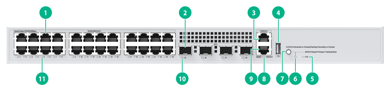
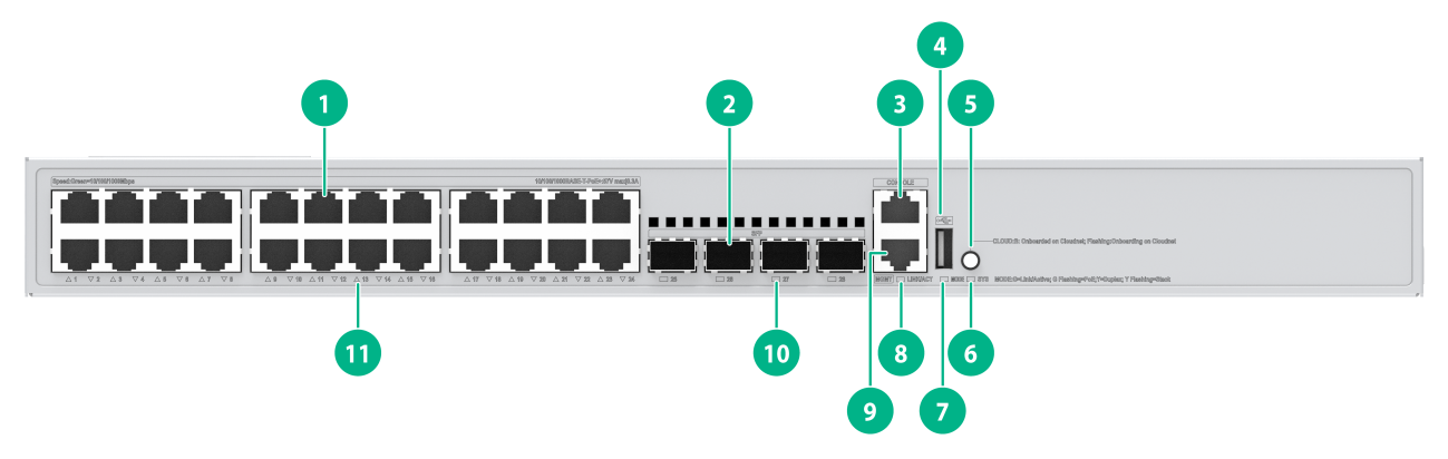
S5135S-8T4S-EI-Q
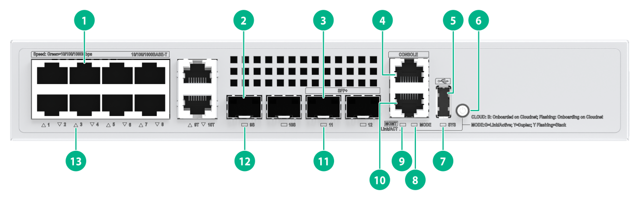
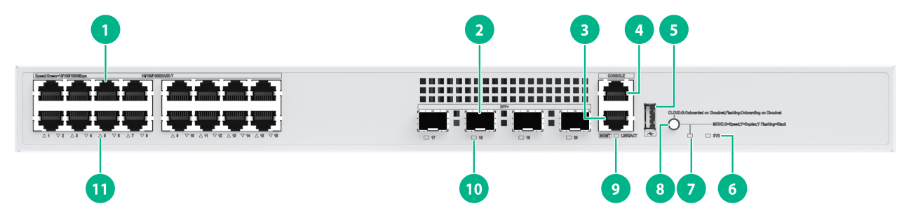
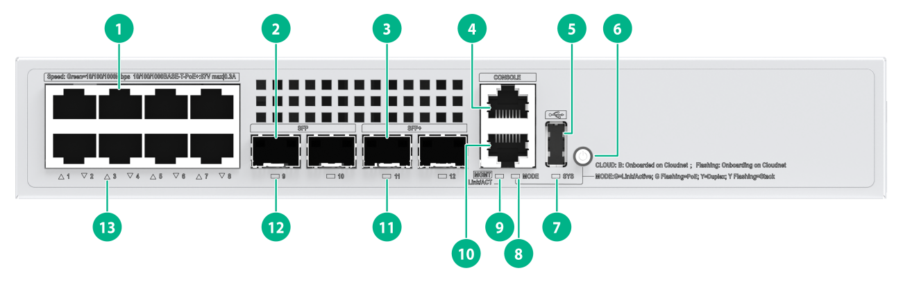
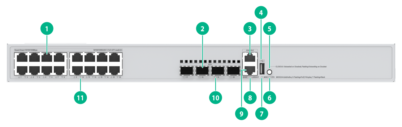
Figure2-1 Front panel

|
(1) 10/100/1000BASE-T autosensing Ethernet port |
(2) SFP port |
|
(3) Console port |
(4) USB port |
|
(5) Mode button (Cloudnet management status LED) |
(6) System status LED (SYS) |
|
(7) Mode LED (MODE) |
(8) Management Ethernet port LED (LINK/ACT) |
|
(9) Management Ethernet port |
(10) SFP port LED |
|
(11) 10/100/1000BASE-T autosensing Ethernet port LED |
|
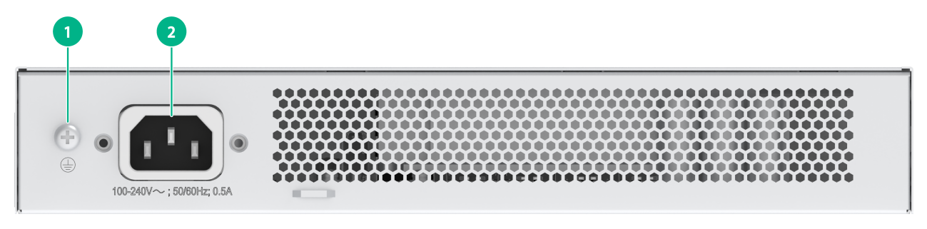
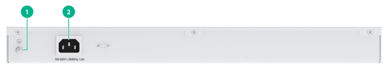
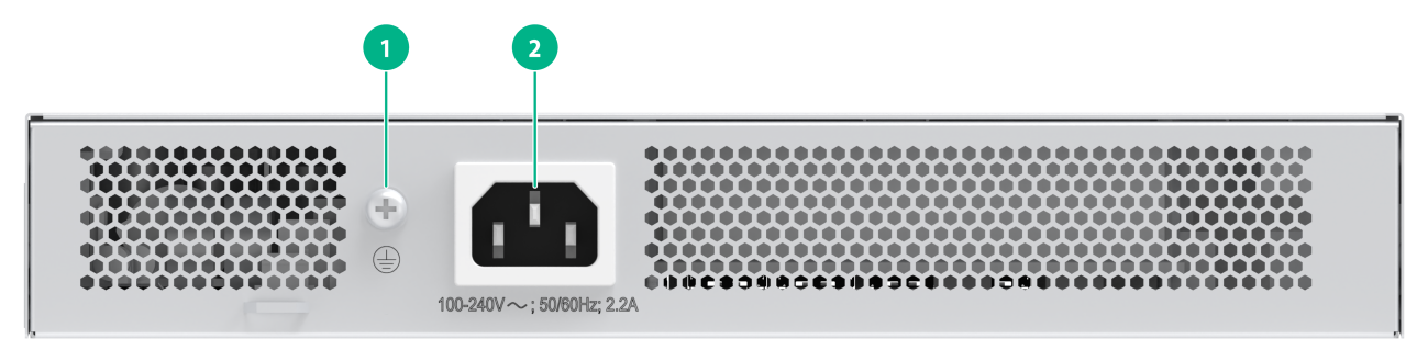
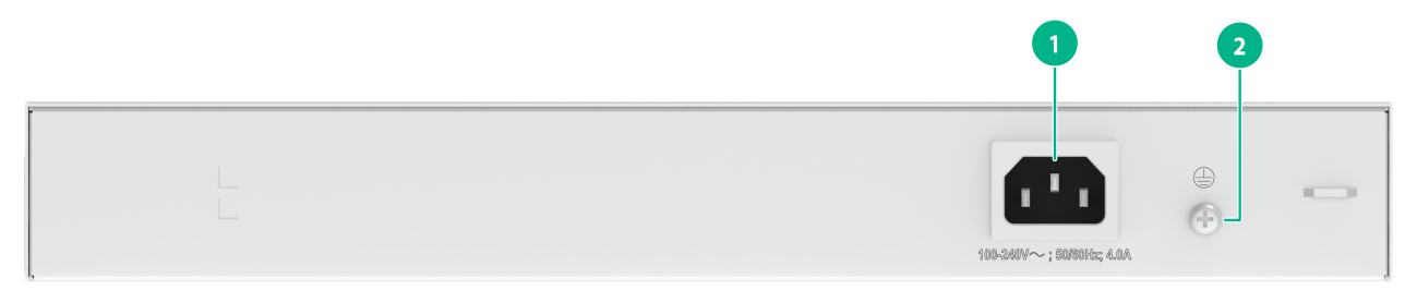
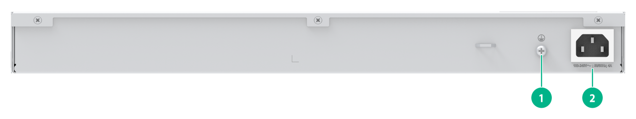
Figure2-2 Rear panel
|
(1) Grounding screw |
(2) AC power receptacle |
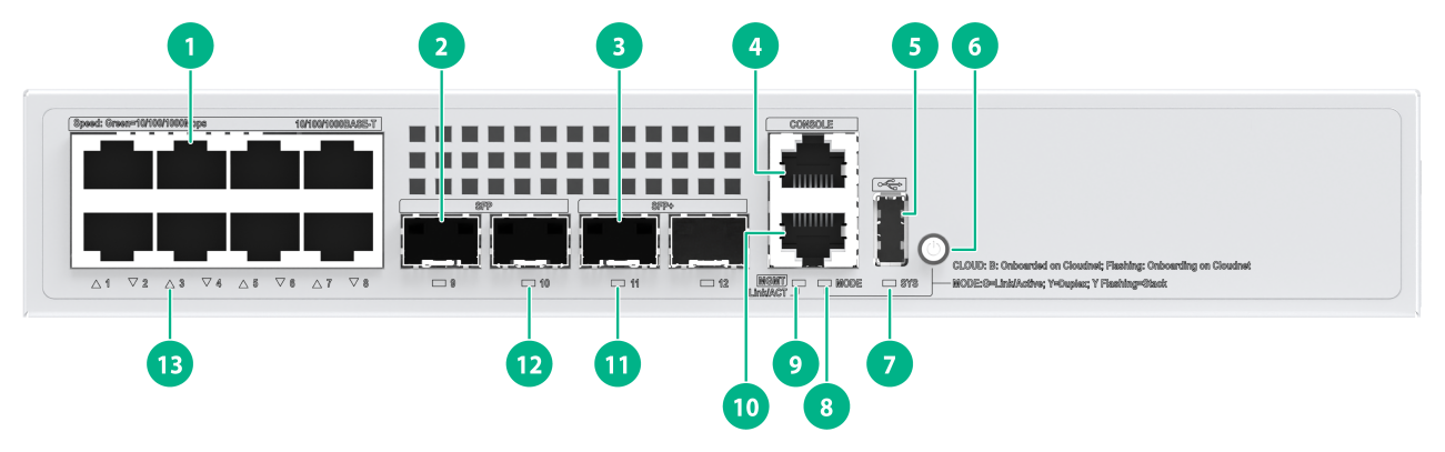
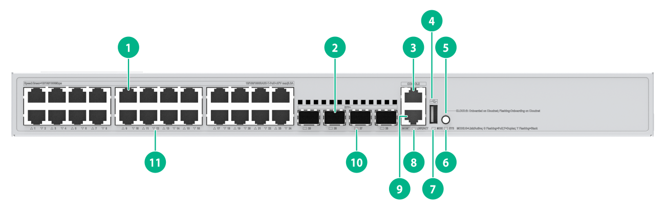
S5135S-8T4XS-EI-Q
Figure2-3 Front panel
|
(1) 10/100/1000BASE-T autosensing Ethernet port |
(2) SFP port |
|
(3) SFP+ port |
(4) Console port |
|
(5) USB port |
(6) Mode button (Cloudnet management status LED) |
|
(7) System status LED (SYS) |
(8) Mode LED (MODE) |
|
(9) Management Ethernet port LED (LINK/ACT) |
(10) Management Ethernet port |
|
(11) SFP+ port LED |
(12) SFP port LED |
|
(13) 10/100/1000BASE-T autosensing Ethernet port LED |
|
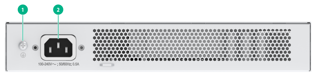
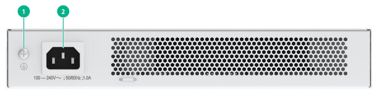
Figure2-4 Rear panel
|
(1) Grounding screw |
(2) AC power receptacle |
S5135S-10T2S2X-EI-Q
Figure2-5 Front panel
|
(1) 10/100/1000BASE-T autosensing Ethernet port |
(2) SFP port |
|
(3) SFP+ port |
(4) Console port |
|
(5) USB port |
(6) Mode button (Cloudnet management status LED) |
|
(7) System status LED (SYS) |
(8) Mode LED (MODE) |
|
(9) Management Ethernet port LED (LINK/ACT) |
(10) Management Ethernet port |
|
(11) SFP+ port LED |
(12) SFP port LED |
|
(13) 10/100/1000BASE-T autosensing Ethernet port LED |
|
Figure2-6 Rear panel
|
(1) Grounding screw |
(2) AC power receptacle |
S5135S-16T4S-EI
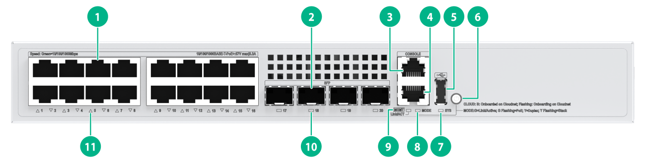
Figure2-7 Front panel
|
(1) 10/100/1000BASE-T autosensing Ethernet port |
(2) SFP port |
|
(3) Console port |
(4) Management Ethernet port |
|
(5) USB port |
(6) Mode button (Cloudnet management status LED) |
|
(7) System status LED (SYS) |
(8) Mode LED (MODE) |
|
(9) Management Ethernet port LED (LINK/ACT) |
(10) SFP port LED |
|
(11) 10/100/1000BASE-T autosensing Ethernet port LED |
|
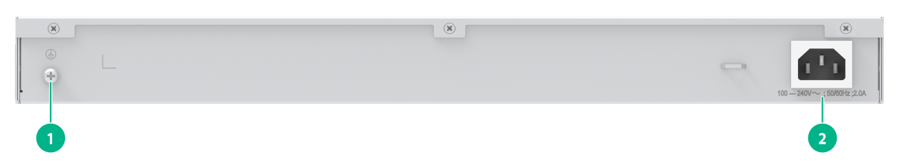
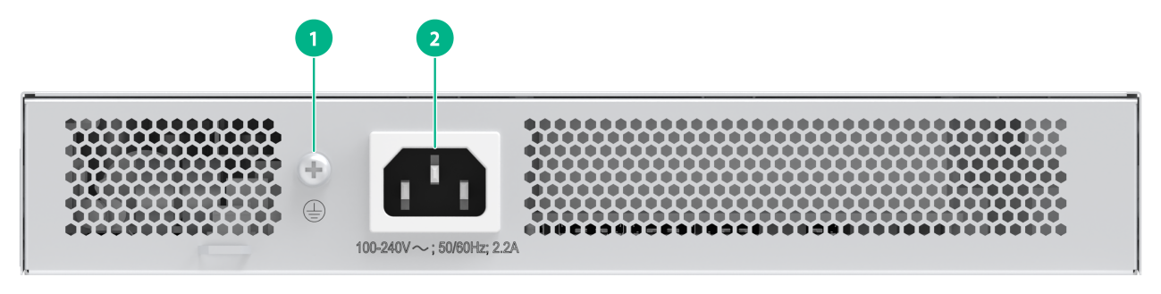
Figure2-8 Rear panel
|
(1) AC power receptacle |
(2) Grounding screw |
S5135S-16T4X-EI-Q
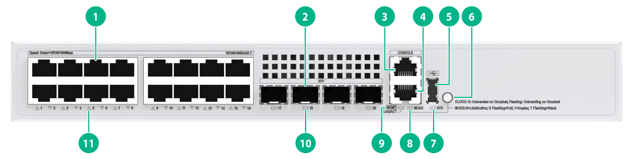
Figure2-9 Front panel
|
(1) 10/100/1000BASE-T autosensing Ethernet port |
(2) SFP+ port |
|
(3) Management Ethernet port |
(4) Console port |
|
(5) USB port |
(6) System status LED (SYS) |
|
(7) Mode LED (MODE) |
(8) Mode button (Cloudnet management status LED) |
|
(9) Management Ethernet port LED (LINK/ACT) |
(10) SFP+ port LED |
|
(11) 10/100/1000BASE-T autosensing Ethernet port LED |
|
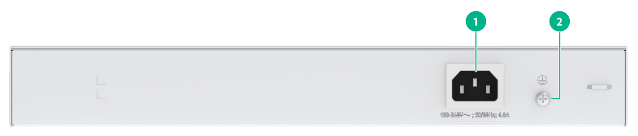
|
(1) Grounding screw |
(2) AC power receptacle |
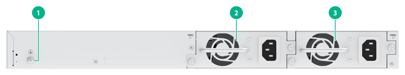
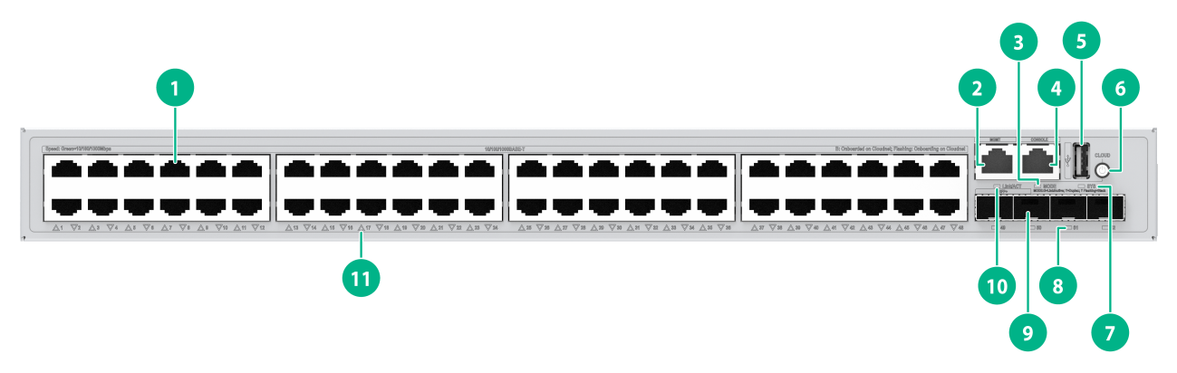
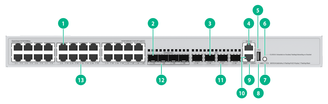
S5135S-24S8T4X-EI
Figure2-11 Front panel
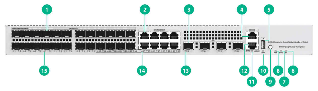
|
(1) SFP port |
(2) 10/100/1000BASE-T autosensing Ethernet port |
|
(3) SFP+ port |
(4) Console port |
|
(5) USB port |
(6) System status LED (SYS) |
|
(7) Mode LED (MODE) |
(8) Power supply 2 status LED (PWR2) |
|
(9) Mode button (Cloudnet management status LED) |
(10) Power supply 1 status LED (PWR1) |
|
(11) Management Ethernet port LED (LINK/ACT) |
(12) Management Ethernet port |
|
(13) SFP+ port LED |
(14) 10/100/1000BASE-T autosensing Ethernet port LED |
|
(15) SFP port LED |
|

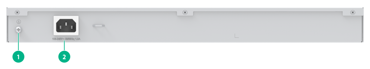
|
(1) Grounding screw |
(2) Power supply 1 (PWR1) |
|
(3) Power supply 2 (PWR2) |
|
The S5135S-24S8T4X-EI switch has two power supply slots on the rear panel. You can install one or two power supplies for the switch as needed. In Figure2-12, two PSR75-12A AC power supplies are installed.
S5135S-24T4S-EI-Q
Figure2-13 Front panel

|
(1) 10/100/1000BASE-T autosensing Ethernet port |
(2) SFP port |
|
(3) Console port |
(4) USB port |
|
(5) System status LED (SYS) |
(6) Mode LED (MODE) |
|
(7) Mode button (Cloudnet management status LED) |
(8) Management Ethernet port LED (LINK/ACT) |
|
(9) Management Ethernet port |
(10) SFP port LED |
|
(11) 10/100/1000BASE-T autosensing Ethernet port LED |
|
|
(1) Grounding screw |
(2) AC power receptacle |
S5135S-24T4X-EI-Q
Figure2-15 Front panel
|
(1) 10/100/1000BASE-T autosensing Ethernet port |
(2) SFP+ port |
|
(3) Console port |
(4) USB port |
|
(5) System status LED (SYS) |
(6) Mode LED (MODE) |
|
(7) Mode button (Cloudnet management status LED) |
(8) Management Ethernet port LED (LINK/ACT) |
|
(9) Management Ethernet port |
(10) SFP+ port LED |
|
(11) 10/100/1000BASE-T autosensing Ethernet port LED |
|
Figure2-16 Rear panel

|
(1) Grounding screw |
(2) AC power receptacle |
S5135S-48S2T4X-EI
Figure2-17 Front panel
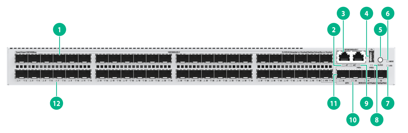
|
(1) SFP port |
(2) 10/100/1000BASE-T autosensing Ethernet port LED |
|
(3) 10/100/1000BASE-T autosensing Ethernet port |
(4) USB port |
|
(5) Mode button (Cloudnet management status LED) |
(6) Mode LED (MODE) |
|
(7) System status LED (SYS) |
(8) Power supply 2 status LED (PWR2) |
|
(9) Power supply 1 status LED (PWR1) |
(10) SFP+ port LED |
|
(11) SFP+ port |
(12) SFP port LED |
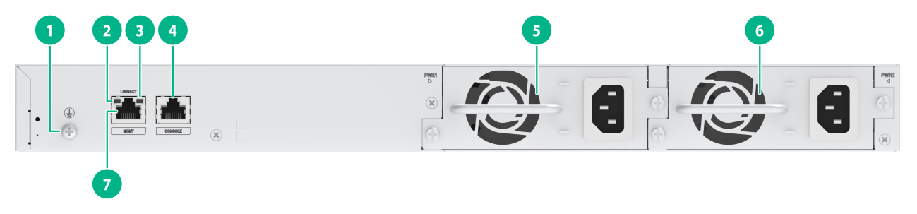
|
(1) Grounding screw |
(2) Management Ethernet port LED (LINK) |
|
(3) Management Ethernet port LED (ACT) |
(4) Console port |
|
(5) Power supply 1 (PWR1) |
(6) Power supply 2 (PWR2) |
|
(7) Management Ethernet port |
|
The S5135S-48S2T4X-EI switch has two power supply slots on the rear panel. You can install one or two power supplies for the switch as needed. In Figure2-18, two PSR75-12A AC power supplies are installed.
S5135S-48ST4X-EI
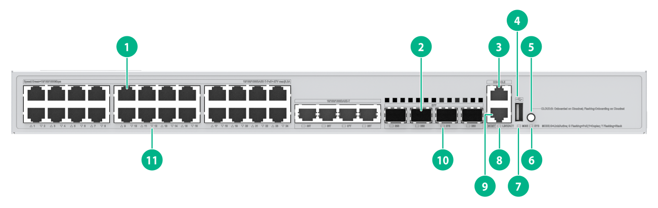
Figure2-19 Front panel
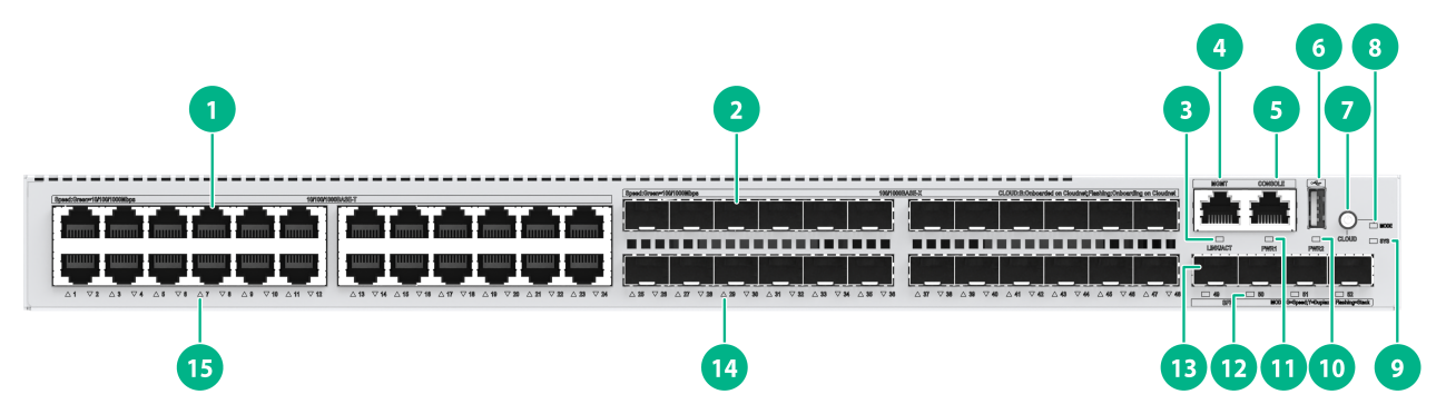
|
(1) 10/100/1000BASE-T autosensing Ethernet port |
(2) SFP port |
|
(3) Management Ethernet port LED (LINK/ACT) |
(4) Management Ethernet port |
|
(5) Console port |
(6) USB port |
|
(7) Mode button (Cloudnet management status LED) |
(8) Mode LED (MODE) |
|
(9) System status LED (SYS) |
(10) Power supply 2 status LED (PWR2) |
|
(11) Power supply 1 status LED (PWR1) |
(12) SFP+ port LED |
|
(13) SFP+ port |
(14) SFP port LED |
|
(15) 10/100/1000BASE-T autosensing Ethernet port LED |
|
|
(1) Grounding screw |
(2) Power supply 1 (PWR1) |
|
(3) Power supply 2 (PWR2) |
|
The S5135S-48ST4X-EI switch has two power supply slots on the rear panel. You can install one or two power supplies for the switch as needed. In Figure2-20, two PSR75-12A AC power supplies are installed.
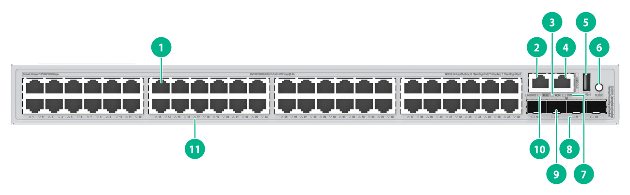
S5135S-48T4S-EI-Q
Figure2-21 Front panel
|
(1) 10/100/1000BASE-T autosensing Ethernet port |
(2) Management Ethernet port |
|
(3) Mode LED (MODE) |
(4) Console port |
|
(5) USB port |
(6) Mode button (Cloudnet management status LED) |
|
(7) System status LED (SYS) |
(8) SFP+ port LED |
|
(9) SFP+ port |
(10) Management Ethernet port LED (LINK/ACT) |
|
(11) 10/100/1000BASE-T autosensing Ethernet port LED |
|

|
(1) Grounding screw |
(2) AC power receptacle |
S5135S-48T4X-EI-Q
Figure2-23 Front panel

|
(1) 10/100/1000BASE-T autosensing Ethernet port |
(2) Management Ethernet port |
|
(3) Mode LED (MODE) |
(4) Console port |
|
(5) USB port |
(6) Mode button (Cloudnet management status LED) |
|
(7) System status LED (SYS) |
(8) SFP+ port LED |
|
(9) SFP+ port |
(10) Management Ethernet port LED (LINK/ACT) |
|
(11) 10/100/1000BASE-T autosensing Ethernet port LED |
|
|
(1) Grounding screw |
(2) AC power receptacle |
S5135S-8FP4S-EI-Q
Figure2-25 Front panel
|
(1) 10/100/1000BASE-T autosensing Ethernet port |
(2) SFP port |
|
(3) Console port |
(4) USB port |
|
(5) Mode button (Cloudnet management status LED) |
(6) System status LED (SYS) |
|
(7) Mode LED (MODE) |
(8) Management Ethernet port LED (LINK/ACT) |
|
(9) Management Ethernet port |
(10) SFP port LED |
|
(11) 10/100/1000BASE-T autosensing Ethernet port LED |
|
Figure2-26 Rear panel
|
(1) Grounding screw |
(2) AC power receptacle |
S5135S-8FP4XS-EI-Q
Figure2-27 Front panel
|
(1) 10/100/1000BASE-T autosensing Ethernet port |
(2) SFP port |
|
(3) SFP+ port |
(4) Console port |
|
(5) USB port |
(6) Mode button (Cloudnet management status LED) |
|
(7) System status LED (SYS) |
(8) Mode LED (MODE) |
|
(9) Management Ethernet port LED (LINK/ACT) |
(10) Management Ethernet port |
|
(11) SFP+ port LED |
(12) SFP port LED |
|
(13) 10/100/1000BASE-T autosensing Ethernet port LED |
|
Figure2-28 Rear panel
|
(1) Grounding screw |
(2) AC power receptacle |
S5135S-16FP4S-EI
Figure2-29 Front panel
|
(1) 10/100/1000BASE-T autosensing Ethernet port |
(2) SFP port |
|
(3) Console port |
(4) Management Ethernet port |
|
(5) USB port |
(6) Mode button (Cloudnet management status LED) |
|
(7) System status LED (SYS) |
(8) Mode LED (MODE) |
|
(9) Management Ethernet port LED (LINK/ACT) |
(10) SFP port LED |
|
(11) 10/100/1000BASE-T autosensing Ethernet port LED |
|
Figure2-30 Rear panel
|
(1) AC power receptacle |
(2) Grounding screw |
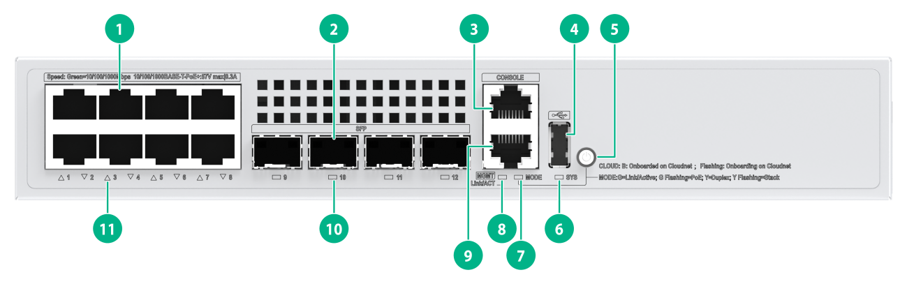
S5135S-16FP4X-EI
Figure2-31 Front panel
|
(1) 10/100/1000BASE-T autosensing Ethernet port |
(2) SFP+ port |
|
(3) Console port |
(4) USB port |
|
(5) Mode button (Cloudnet management status LED) |
(6) System status LED (SYS) |
|
(7) Mode LED (MODE) |
(8) Management Ethernet port LED (LINK/ACT) |
|
(9) Management Ethernet port |
(10) SFP+ port LED |
|
(11) 10/100/1000BASE-T autosensing Ethernet port LED |
|
Figure2-32 Rear panel

|
(1) Grounding screw |
(2) AC power receptacle |
S5135S-24FP4S4X-EI
Figure2-33 Front panel
|
(1) 10/100/1000BASE-T autosensing Ethernet port |
(2) SFP port |
|
(3) SFP+ port |
(4) Console port |
|
(5) USB port |
(6) Mode button (Cloudnet management status LED) |
|
(7) System status LED (SYS) |
(8) Mode LED (MODE) |
|
(9) Management Ethernet port LED (LINK/ACT) |
(10) Management Ethernet port |
|
(11) SFP+ port LED |
(12) SFP port LED |
|
(13) 10/100/1000BASE-T autosensing Ethernet port LED |
|
Figure2-34 Rear panel

|
(1) Grounding screw |
(2) AC power receptacle |
S5135S-24FP4T4S-EI
Figure2-35 Front panel
|
(1) 10/100/1000BASE-T autosensing Ethernet port |
(2) SFP port |
|
(3) Console port |
(4) USB port |
|
(5) Mode button (Cloudnet management status LED) |
(6) System status LED (SYS) |
|
(7) Mode LED (MODE) |
(8) Management Ethernet port LED (LINK/ACT) |
|
(9) Management Ethernet port |
(10) SFP port LED |
|
(11) 10/100/1000BASE-T autosensing Ethernet port LED |
|
Figure2-36 Rear panel

|
(1) Grounding screw |
(2) AC power receptacle |
S5135S-24P4S-EI
Figure2-37 Front panel
|
(1) 10/100/1000BASE-T autosensing Ethernet port |
(2) SFP port |
|
(3) Console port |
(4) USB port |
|
(5) Mode button (Cloudnet management status LED) |
(6) System status LED (SYS) |
|
(7) Mode LED (MODE) |
(8) Management Ethernet port LED (LINK/ACT) |
|
(9) Management Ethernet port |
(10) SFP port LED |
|
(11) 10/100/1000BASE-T autosensing Ethernet port LED |
|
Figure2-38 Rear panel
|
(1) Grounding screw |
(2) AC power receptacle |
S5135S-24P4X-EI
Figure2-39 Front panel
|
(1) 10/100/1000BASE-T autosensing Ethernet port |
(2) SFP+ port |
|
(3) Console port |
(4) USB port |
|
(5) Mode button (Cloudnet management status LED) |
(6) System status LED (SYS) |
|
(7) Mode LED (MODE) |
(8) Management Ethernet port LED (LINK/ACT) |
|
(9) Management Ethernet port |
(10) SFP+ port LED |
|
(11) 10/100/1000BASE-T autosensing Ethernet port LED |
|
Figure2-40 Rear panel

|
(1) Grounding screw |
(2) AC power receptacle |
S5135S-48FP4S-EI
Figure2-41 Front panel
|
(1) 10/100/1000BASE-T autosensing Ethernet port |
(2) Management Ethernet port |
|
(3) Mode LED (MODE) |
(4) Console port |
|
(5) USB port |
(6) Mode button (Cloudnet management status LED) |
|
(7) System status LED (SYS) |
(8) SFP port LED |
|
(9) SFP port |
(10) Management Ethernet port LED (LINK/ACT) |
|
(11) 10/100/1000BASE-T autosensing Ethernet port LED |
|
Figure2-42 Rear panel

|
(1) Grounding screw |
(2) AC power receptacle |
S5135S-48FP4X-EI
Figure2-43 Front panel

|
(1) 10/100/1000BASE-T autosensing Ethernet port |
(2) Management Ethernet port |
|
(3) Mode LED (MODE) |
(4) Console port |
|
(5) USB port |
(6) Mode button (Cloudnet management status LED) |
|
(7) System status LED (SYS) |
(8) SFP+ port LED |
|
(9) SFP+ port |
(10) Management Ethernet port LED (LINK/ACT) |
|
(11) 10/100/1000BASE-T autosensing Ethernet port LED |
|
Figure2-44 Rear panel

|
(1) Grounding screw |
(2) AC power receptacle |
S5135S-48P4S-EI
Figure2-45 Front panel

|
(1) 10/100/1000BASE-T autosensing Ethernet port |
(2) Management Ethernet port |
|
(3) Mode LED (MODE) |
(4) Console port |
|
(5) USB port |
(6) Mode button (Cloudnet management status LED) |
|
(7) System status LED (SYS) |
(8) SFP port LED |
|
(9) SFP port |
(10) Management Ethernet port LED (LINK/ACT) |
|
(11) 10/100/1000BASE-T autosensing Ethernet port LED |
|
Figure2-46 Rear panel

|
(1) Grounding screw |
(2) AC power receptacle |
S5135S-48P4X-EI
Figure2-47 Front panel

|
(1) 10/100/1000BASE-T autosensing Ethernet port |
(2) Management Ethernet port |
|
(3) Mode LED (MODE) |
(4) Console port |
|
(5) USB port |
(6) Mode button (Cloudnet management status LED) |
|
(7) System status LED (SYS) |
(8) SFP+ port LED |
|
(9) SFP+ port |
(10) Management Ethernet port LED (LINK/ACT) |
|
(11) 10/100/1000BASE-T autosensing Ethernet port LED |
|

|
(1) AC power receptacle |
(2) Grounding screw |
3 Removable components
Some switch models use removable power supplies. Table3-1 describes the removable components available for the switch.
Table3-1 Compatibility matrix between switches and removable components
|
Removable component model |
S5135S-24S8T4X-EI S5135S-48ST4X-EI S5135S-48S2T4X-EI |
|
Removable power supplies |
|
|
CA-70A12 |
Supported |
|
PSR75-12A |
Supported |
|
PSR180-12D-B |
Supported |
One power supply can meet the power requirement of the switch. You can install two power supplies on the switch for 1+1 redundancy. The device supports installation of both an AC power supply and a DC power supply.
The removable components available for the switch are subject to change over time. For the most recent list of the removable components, see the release notes for the switch.
You can use the display device manuinfo power command to read the electrical label information of the power supplies. The CA-70A12 power supply does not support electrical label information reading.
4 Removable power supplies
70 W power supply (CA-70A12)
View
Figure4-1 CA-70A12 power supply view

Functions
The CA-70A12 is an AC and DC input and DC output power supply. It provides a maximum output of 70 W.
Table4-1 CA-70A12 power supply features
|
Feature |
Description |
|
Protection function |
The power supply provides protection against input overcurrent, input undervoltage, output overvoltage, output current limiting, output shortcircuit, and overtemperature conditions. |
|
Support for redundancy |
Two power supplies can be connected in parallel to achieve 1+1 redundancy and load balancing. |
|
Support for hot swapping |
You can remove one of the power supplies in 1+1 redundancy when the switch is operating. |
Technical specifications
Table4-2 Technical specifications
|
Item |
Specification |
|
Dimensions (H × W × D, including the handle) |
41.1 × 101.6 × 207 mm (1.62 × 4.00 × 8.15 in) |
|
Weight |
0.6 kg (1.32 lb) |
|
Rated input voltage range |
AC input: 100 VAC to 240 VAC @ 50 Hz or 60 Hz HVDC input: 240 VDC |
|
Max input voltage range |
AC input: 90 VAC to 290 VAC @ 47 Hz to 63 Hz HVDC input: 180 VDC to 320 VDC |
|
Rated input current |
N/A |
|
Rated output current |
5.83 A |
|
Rated output voltage |
12 V |
|
Rated output power |
70 W |
|
Melting current of power supply fuse |
10 A/250 V |
75 W power supply (PSR75-12A)
View
Figure4-2 PSR75-12A power supply view
|
(1) Mounting screws |
(2) Power input receptacle |
|
(3) Latch |
(4) Handle |
Functions
The PSR75-12A is an AC and DC input and DC output power supply. It provides a maximum output of 75 W.
Table4-3 PSR75-12A power supply features
|
Feature |
Description |
|
Protection function |
The power supply provides protection against input overcurrent, input undervoltage, output overvoltage, output current limiting, output shortcircuit, and overtemperature conditions. |
|
Support for redundancy |
Two power supplies can be connected in parallel to achieve 1+1 redundancy and load balancing. |
|
Support for hot swapping |
You can remove one of the power supplies in 1+1 redundancy when the switch is operating. |
Technical specifications
Table4-4 Technical specifications
|
Item |
Specification |
|
Dimensions (H × W × D, including the handle) |
41.1 × 101.6 × 207 mm (1.62 × 4.00 × 8.15 in) |
|
Weight |
0.72 kg (1.59 lb) |
|
Rated input voltage range |
AC input: 100 VAC to 240 VAC @ 50 Hz or 60 Hz HVDC input: 240 VDC |
|
Max input voltage range |
AC input: 90 VAC to 290 VAC @ 47 Hz to 63 Hz HVDC input: 180 VDC to 320 VDC |
|
Rated input current |
N/A |
|
Rated output current |
6.3 A |
|
Rated output voltage |
12 V |
|
Rated output power |
75 W |
|
Melting current of power supply fuse |
3.15 A/250 V |
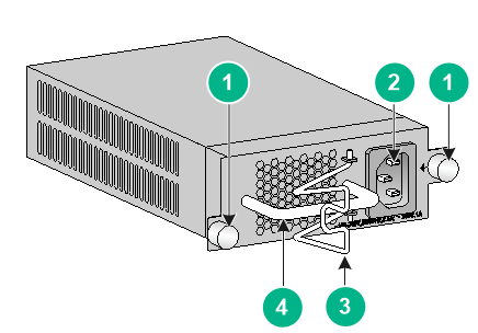
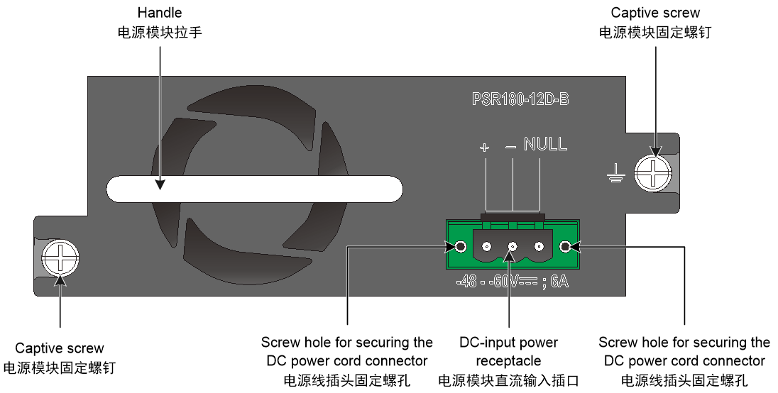
180 W power supply (PSR180-12D-B)
View
Figure4-3 PSR180-12D-B power supply view
Functions
The PSR180-12D-B is a DC input and DC output power supply. It provides a maximum output of 180 W.
Table4-5 PSR180-12D-B power supply features (1)
|
Feature |
Description |
|
Protection function |
The power supply provides protection against output overvoltage, shortcircuit, current limiting, and overtemperature conditions. |
|
Support for redundancy |
Two power supplies can be connected in parallel to achieve 1+1 redundancy and load balancing. |
|
Support for hot swapping |
You can remove one of the power supplies in 1+1 redundancy when the switch is operating. Before removing the power supply, disconnect the power supply from the external power supply system. |
Table4-6 PSR180-12D-B power supply features (2)
|
Protection function |
PSR180-12D-B |
|
|
Protection state |
Support for auto-recovery |
|
|
Protection function |
The power supply is locked and does not supply power. |
Not supported. |
|
Shortcircuit protection |
The power supply is locked and does not supply power. |
Not supported. |
|
Overcurrent protection |
The power supply is locked and does not supply power. |
Not supported. |
|
Overtemperature protection |
The power supply does not supply power. |
The power supply automatically restores power supply after the temperature decreases to an acceptable range. |
After a power supply is locked, it cannot automatically restore power supply after the problems are resolved. Follow this procedure to restore the power supply operation:
1. Disconnect the power cord from the external power supply system.
2. Disconnect the power cord from the power supply and then reconnect it.
3. Connect the power cord to the external power supply system.
Technical specifications
Table4-7 Technical specifications
|
Item |
Specification |
|
Dimensions (H × W × D, including the handle) |
101.6 × 41.1 × 177 mm (4.00 × 1.62 × 6.97 in) |
|
Weight |
0.8 kg (1.76 lb) |
|
Rated input voltage range |
–48 VDC to –60 VDC |
|
Max input voltage range |
–36 VDC to –72 VDC |
|
Rated input current |
N/A |
|
Rated output current |
15 A |
|
Rated output voltage |
12 V |
|
Rated output power |
180 W |
|
Melting current of power supply fuse |
8 A/125 V |
5 Ports and LEDs
Ports
Console port
Table5-1 Console port specifications
|
Item |
Specification |
|
Connector type |
RJ-45 |
|
Compliant standard |
EIA/TIA-232 |
|
Transmission baud rate |
9600 bps (default) to 115200 bps |
|
Services |
· Provides connection to an ASCII terminal · Provides connection to the serial port of a local PC running terminal emulation program |
|
Compatible switch models |
All switch models |
Management Ethernet port
The switch has one management Ethernet port on the front panel. You can connect the port to a local PC for software loading and debugging or to a remote management station for remote management.
Table5-2 Management Ethernet port specifications
|
Item |
Specification |
|
Connector type |
RJ-45 |
|
Transmission rate, duplex mode, and auto MDI/MDI-X |
· 10 Mbps, half/full-duplex · 100 Mbps, half/full-duplex · MDI/MDI-X, autosensing |
|
Transmission medium |
Category-5 or above twisted pair cable |
|
Max transmission distance |
100 m (328.08 ft) |
|
Compliant standard |
IEEE 802.3i IEEE 802.3u IEEE 802.3ab |
|
Functions and services |
Used for upgrading and managing applications and Boot ROM |
|
Compatible switch models |
All switch models |
10/100/1000BASE-T autosensing Ethernet port
Table5-3 10/100/1000BASE-T autosensing Ethernet port specifications
|
Item |
Specification |
|
Connector type |
RJ-45 |
|
Transmission rate, duplex mode, and auto MDI/MDI-X |
· 10 Mbps, half/full-duplex · 100 Mbps, half/full-duplex · 1000 Mbps, full-duplex · MDI/MDI-X, autosensing |
|
Max transmission distance |
100 m (328.08 ft) |
|
Transmission medium |
Category-5 or above twisted pair cable |
|
Compliant standard |
IEEE 802.3i IEEE 802.3u IEEE 802.3ab |
|
Compatible switch models |
All switch models |
SFP port
Table5-4 SFP port specifications
|
Item |
Specification |
|
Available transceiver modules and cables |
· See FE SFP transceiver modules described in Table5-5. · See GE SFP transceiver modules and cables described in Table5-6. |
|
Compatible switch models |
S5135S-8FP4S-EI-Q, S5135S-8FP4XS-EI-Q, S5135S-8T4XS-EI-Q, S5135S-8T4S-EI-Q, S5135S-10T2S2X-EI-Q, S5135S-16T4S-EI, S5135S-24T4S-EI-Q, S5135S-48T4S-EI-Q, S5135S-16FP4S-EI, S5135S-24FP4S4X-EI, S5135S-24FP4T4S-EI, S5135S-24P4S-EI, S5135S-24S8T4X-EI, S5135S-48FP4S-EI, S5135S-48P4S-EI, S5135S-48S2T4X-EI, S5135S-48ST4X-EI |
|
Restrictions and guidelines |
· To use the SFP-GE-T, SFP-GE-T-D, or transceiver modules with a maximum transmission distance greater than or equal to 80 km (49.71 miles) on the following switch models, make sure the ambient temperature does not exceed 40°C (104°F). ¡ S5135S-8T4XS-EI-Q ¡ S5135S-8T4S-EI-Q ¡ S5135S-16FP4S-EI ¡ S5135S-16T4S-EI ¡ S5135S-10T2S2X-EI-Q ¡ S5135S-8FP4S-EI-Q ¡ S5135S-8FP4XS-EI-Q ¡ S5135S-48T4S-EI-Q ¡ S5135S-48S2T4X-EI ¡ S5135S-48ST4X-EI ¡ S5135S-24S8T4X-EI ¡ S5135S-24T4S-EI-Q · When you use the following transceiver modules on an S5135S-48S2T4X-EI or S5135S-48ST4X-EI switch, make sure the number of the transceiver modules does not exceed 30. ¡ SFP-GE-T. ¡ SFP-GE-T-D. ¡ Transceiver modules with a maximum transmission distance greater than or equal to 80 km (49.71 miles). · The S5135S-24T4S-EI-Q switch does not support FE SFP transceiver modules. |
Table5-5 FE SFP transceiver modules available for the SFP ports
|
FE SFP transceiver module |
Central wavelength (nm) |
Connector |
Fiber type and diameter (µm) |
Max transmission distance |
|
SFP-FE-SX-MM1310-A |
1310 |
LC |
Multi-mode, 50/125 |
2 km (1.24 miles) |
|
Multi-mode, 62.5/125 |
||||
|
SFP-FE-LX-SM1310-A |
1310 |
LC |
Single-mode, 9/125 |
15 km (9.32 miles) |
|
SFP-FE-LX-SM1310-D |
1310 |
LC |
Single-mode, 9/125 |
15 km (9.32 miles) |
|
SFP-FE-LH40-SM1310 |
1310 |
LC |
Single-mode, 9/125 |
40 km (24.86 miles) |
|
SFP-FE-LH80-SM1550 |
1550 |
LC |
Single-mode, 9/125 |
80 km (49.71 miles) |
|
SFP-FE-LX-SM1310-BIDI |
TX: 1310 RX: 1550 |
LC |
Single-mode, 9/125 |
15 km (9.32 miles) |
|
SFP-FE-LX-SM1550-BIDI |
TX: 1550 RX: 1310 |
LC |
Single-mode, 9/125 |
15 km (9.32 miles) |
|
|
IMPORTANT: The SFP-FE-LX-SM1310-BIDI and SFP-FE-LX-SM1550-BIDI transceiver modules must be used in pairs. For example, if one end uses the SFP-FE-LX-SM1310-BIDI transceiver module, the other end must use the SFP-FE-LX-SM1550-BIDI transceiver module. |
Table5-6 GE SFP transceiver modules and cables available for the SFP ports
|
GE SFP transceiver module/cable |
Central wavelength (nm) |
Connector |
Cable/Fiber type and diameter (µm) |
Modal bandwidth (MHz*km) |
Max. transmission distance |
|
SFP copper transceiver modules |
|||||
|
SFP-GE-T |
N/A |
RJ-45 |
Twisted pair cable |
N/A |
100 m (328.08 ft) |
|
SFP-GE-T-D |
N/A |
RJ-45 |
Twisted pair cable |
N/A |
100 m (328.08 ft) |
|
SFP optical transceiver modules |
|||||
|
SFP-GE-SX-MM850-A |
850 |
LC |
Multi-mode, 50/125 |
500 |
550 m (1804.46 ft) |
|
400 |
500 m (1640.42 ft) |
||||
|
Multi-mode, 62.5/125 |
200 |
275 m (902.23 ft) |
|||
|
160 |
220 m (721.78 ft) |
||||
|
SFP-GE-SX-MM850-D |
850 |
LC |
Multi-mode, 50/125 |
500 |
550 m (1804.46 ft) |
|
400 |
500 m (1640.42 ft) |
||||
|
Multi-mode, 62.5/125 |
200 |
275 m (902.23 ft) |
|||
|
160 |
220 m (721.78 ft) |
||||
|
SFP-GE-SX-MM850-S |
850 |
LC |
Multi-mode, 50/125 |
500 |
550 m (1804.46 ft) |
|
400 |
500 m (1640.42 ft) |
||||
|
Multi-mode, 62.5/125 |
200 |
275 m (902.23 ft) |
|||
|
160 |
220 m (721.78 ft) |
||||
|
SFP-GE-LX-SM1310-A |
1310 |
LC |
Single-mode, 9/125 |
N/A |
10 km (6.21 miles) |
|
Multi-mode, 50/125 |
500/400 |
550 m (1804.46 ft) |
|||
|
Multi-mode, 62.5/125 |
500 |
550 m (1804.46 ft) |
|||
|
SFP-GE-LX-SM1310-D |
1310 |
LC |
Single-mode, 9/125 |
N/A |
10 km (6.21 miles) |
|
SFP-GE-LX-SM1310-S |
1310 |
LC |
Single-mode, 9/125 |
N/A |
10 km (6.21 miles) |
|
SFP-GE-LH40-SM1310 |
1310 |
LC |
Single-mode, 9/125 |
N/A |
40 km (24.86 miles) |
|
SFP-GE-LH40-SM1310-D |
1310 |
LC |
Single-mode, 9/125 |
N/A |
40 km (24.86 miles) |
|
SFP-GE-LH40-SM1550 |
1550 |
LC |
Single-mode, 9/125 |
N/A |
40 km (24.86 miles) |
|
SFP-GE-LH80-SM1550 |
1550 |
LC |
Single-mode, 9/125 |
N/A |
80 km (49.71 miles) |
|
SFP-GE-LH80-SM1550-D |
1550 |
LC |
Single-mode, 9/125 |
N/A |
80 km (49.71 miles) |
|
SFP-GE-LH100-SM1550 |
1550 |
LC |
Single-mode, 9/125 |
N/A |
100 km (62.14 miles) |
|
SFP-GE-LX-SM1310-BIDI |
TX: 1310 RX: 1490 |
LC |
Single-mode, 9/125 |
N/A |
10 km (6.21 miles) |
|
SFP-GE-LX-SM1490-BIDI |
TX: 1490 RX: 1310 |
LC |
Single-mode, 9/125 |
N/A |
10 km (6.21 miles) |
|
SFP-GE-LH40-SM1310-BIDI |
TX: 1310 RX: 1550 |
LC |
Single-mode, 9/125 |
N/A |
40 km (24.86 miles) |
|
SFP-GE-LH40-SM1550-BIDI |
TX: 1550 RX: 1310 |
LC |
Single-mode, 9/125 |
N/A |
40 km (24.86 miles) |
|
SFP-GE-LH70-SM1490-BIDI |
TX: 1490 RX: 1550 |
LC |
Single-mode, 9/125 |
N/A |
70 km (43.50 miles) |
|
SFP-GE-LH70-SM1550-BIDI |
TX: 1550 RX: 1490 |
LC |
Single-mode, 9/125 |
N/A |
70 km (43.50 miles) |
|
SFP cable |
|||||
|
SFP-STACK-Kit |
N/A |
N/A |
SFP cable |
N/A |
1.5 m (4.92 ft) |
|
|
IMPORTANT: The SFP-GE-LX-SM1310-BIDI and SFP-GE-LX-SM1490-BIDI transceiver modules, the SFP-GE-LH40-SM1310-BIDI and SFP-GE-LH40-SM1550-BIDI transceiver modules, and the SFP-GE-LH70-SM1490-BIDI and SFP-GE-LH70-SM1550-BIDI transceiver modules must be used in pairs. For example, if one end uses an SFP-GE-LX-SM1310-BIDI transceiver module, the other end must use an SFP-GE-LX-SM1490-BIDI transceiver module. |
|
|
NOTE: · As a best practice, use H3C transceiver modules and cables for the switch. · The H3C transceiver modules and cables are subject to change over time. For the most recent list of H3C transceiver modules and cables, contact your H3C Support or marketing staff. · For more information about H3C transceiver modules and cables, see H3C Transceiver Modules User Guide. |
SFP+ port
Table5-7 SFP+ port specifications
|
Item |
Specification |
|
Available transceiver modules and cables |
· See GE SFP transceiver modules and cables described in Table5-6 · See 10GE SFP+ transceiver modules and cables described in Table5-8 and Table5-9 |
|
Compatible switch models |
S5135S-8FP4XS-EI-Q, S5135S-8T4XS-EI-Q, S5135S-10T2S2X-EI-Q, S5135S-16T4X-EI-Q, S5135S-24T4X-EI-Q, S5135S-48T4X-EI-Q, S5135S-16FP4X-EI, S5135S-24FP4S4X-EI, S5135S-24P4X-EI, S5135S-24S8T4X-EI, S5135S-48FP4X-EI, S5135S-48P4X-EI, S5135S-48S2T4X-EI, S5135S-48ST4X-EI |
|
Restrictions and guidelines |
· To use the SFP-GE-T, SFP-GE-T-D, or transceiver modules with a maximum transmission distance greater than or equal to 80 km (49.71 miles) on the following switch models, make sure the ambient temperature does not exceed 40°C (104°F). ¡ S5135S-8T4XS-EI-Q ¡ S5135S-10T2S2X-EI-Q ¡ S5135S-8FP4XS-EI-Q ¡ S5135S-48T4X-EI-Q ¡ S5135S-48S2T4X-EI ¡ S5135S-48ST4X-EI ¡ S5135S-24S8T4X-EI ¡ S5135S-24T4X-EI-Q ¡ S5135S-16T4X-EI-Q · When you use the following transceiver modules on an S5135S-48S2T4X-EI or S5135S-48ST4X-EI switch, make sure the number of the transceiver modules does not exceed 30. ¡ SFP-GE-T. ¡ SFP-GE-T-D. ¡ Transceiver modules with a maximum transmission distance greater than or equal to 80 km (49.71 miles). |
Table5-8 10GE SFP+ transceiver modules available for the SFP+ ports
|
10GE SFP+ transceiver module |
Central wavelength (nm) |
Connector |
Fiber type and diameter (µm) |
Modal bandwidth (MHz*km) |
Max. transmission distance |
|
SFP-XG-SX-MM850-D |
850 |
LC |
Multi-mode, 50/125 |
2000 |
300 m (984.25 ft) |
|
500 |
82 m (269.03 ft) |
||||
|
400 |
66 m (216.54 ft) |
||||
|
Multi-mode, 62.5/125 |
200 |
33 m (108.27 ft) |
|||
|
160 |
26 m (85.30 ft) |
||||
|
SFP-XG-SX-MM850-E |
850 |
LC |
Multi-mode, 50/125 |
2000 |
300 m (984.25 ft) |
|
500 |
82 m (269.03 ft) |
||||
|
400 |
66 m (216.54 ft) |
||||
|
Multi-mode, 62.5/125 |
200 |
33 m (108.27 ft) |
|||
|
160 |
26 m (85.30 ft) |
||||
|
SFP-XG-SX-MM850-S |
850 |
LC |
Multi-mode, 50/125 |
2000 |
300 m (984.25 ft) |
|
500 |
82 m (269.03 ft) |
||||
|
400 |
66 m (216.54 ft) |
||||
|
Multi-mode, 62.5/125 |
200 |
33 m (108.27 ft) |
|||
|
160 |
26 m (85.30 ft) |
||||
|
SFP-XG-LX-SM1310-D |
1310 |
LC |
Single-mode, 9/125 |
N/A |
10 km (6.21 miles) |
|
SFP-XG-LX-SM1310-E |
1310 |
LC |
Single-mode, 9/125 |
N/A |
10 km (6.21 miles) |
|
SFP-XG-LX-SM1310-S |
1310 |
LC |
Single-mode |
N/A |
10 km (6.21 miles) |
|
SFP-XG-LH40-SM1550 |
1550 |
LC |
Single-mode, 9/125 |
N/A |
40 km (24.86 miles) |
|
SFP-XG-LH40-SM1550-D |
1550 |
LC |
Single-mode, 9/125 |
N/A |
40 km (24.86 miles) |
|
SFP-XG-LH80-SM1550 |
1550 |
LC |
Single-mode, 9/125 |
N/A |
80 km (49.71 miles) |
|
SFP-XG-LH80-SM1550-D |
1550 |
LC |
Single-mode, 9/125 |
N/A |
80 km (49.71 miles) |
|
SFP-XG-LX-SM1270-BIDI |
TX: 1270 RX: 1330 |
LC |
Single-mode, 9/125 |
N/A |
10 km (6.21 miles) |
|
SFP-XG-LX-SM1330-BIDI |
TX: 1330 RX: 1270 |
LC |
Single-mode, 9/125 |
N/A |
10 km (6.21 miles) |
|
SFP-XG-LH40-SM1270-BIDI |
TX: 1270 RX: 1330 |
LC |
Single-mode, 9/125 |
N/A |
40 km (24.86 miles) |
|
SFP-XG-LH40-SM1330-BIDI |
TX: 1330 RX: 1270 |
LC |
Single-mode, 9/125 |
N/A |
40 km (24.86 miles) |
|
|
IMPORTANT: The SFP-XG-LX-SM1270-BIDI and SFP-XG-LX-SM1330-BIDI transceiver modules, and SFP-XG-LH40-SM1270-BIDI and SFP-XG-LH40-SM1330-BIDI transceiver modules must be used in pairs. For example, if one end uses an SFP-XG-LX-SM1270-BIDI transceiver module, the other end must use an SFP-XG-LX-SM1330-BIDI transceiver module. |
Table5-9 10GE SFP+ copper and fiber cables available for the SFP+ ports
|
10GE SFP+ cable |
Cable length |
|
SFP+ copper cable |
|
|
LSWM1STK |
0.65 m (2.13 ft) |
|
LSWM2STK |
1.2 m (3.94 ft) |
|
LSWM3STK |
3 m (9.84 ft) |
|
LSTM1STK |
5 m (16.40 ft) |
|
SFP+ fiber cable |
|
|
SFP-XG-D-AOC-7M |
7 m (22.97 ft) |
|
SFP-XG-D-AOC-10M |
10 m (32.81 ft) |
|
SFP-XG-D-AOC-20M |
20 m (65.62 ft) |
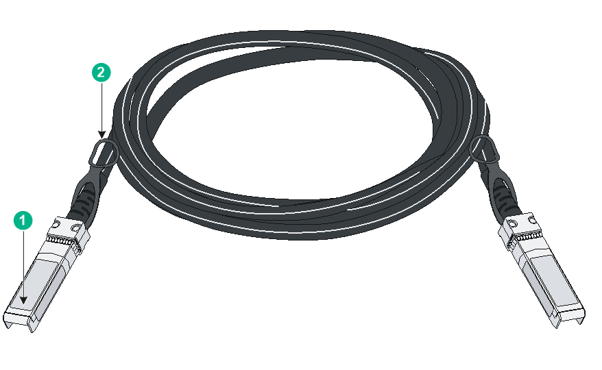
Figure5-1 SFP+ cable
|
(1) Connector |
(2) Pull latch |
|
|
NOTE: · As a best practice, use H3C transceiver modules and cables for the switch. · The H3C transceiver modules and cables are subject to change over time. For the most recent list of H3C transceiver modules and cables, contact your H3C Support or marketing staff. · For more information about H3C transceiver modules and cables, see H3C Transceiver Modules User Guide. |
Combo interface
An S5135S-10T2S2X-EI-Q or S5135S-48S2T4X-EI switch provides two fixed combo interfaces on the front panel. An S5135S-24FP4S4X-EI or S5135S-24FP4T4S-EI switch provides four fixed combo interfaces on the front panel. An S5135S-24S8T4X-EI switch provides eight fixed combo interfaces on the front panel.
Each combo interface contains an SFP port and a 10/100/1000BASE-T autosensing Ethernet port. Only one of these two ports operates at a time.
LEDs
System status LED
The system status LED shows the operating status of the switch.
Table5-10 System status LED description
|
LED mark |
Status |
Description |
|
SYS |
Steady yellow |
Boot ROM booting stage. |
|
Steady green |
Linux kernel booting stage, or the switch has started up correctly. |
|
|
Flashing green (1 Hz) |
Software image loading and decompressing stage, or software booting stage. |
|
|
Steady red |
The switch has failed POST or the switch is faulty. |
|
|
Off |
The switch is powered off or has not started up correctly. |
Management Ethernet port LED
Table5-11 Management Ethernet port LED description
|
LED mark |
Status |
Description |
|
ACT/LINK |
Steady green |
A link is present on the port. |
|
Flashing green |
The port is receiving or sending data. |
|
|
Off |
No link is present on the port. |
Power supply status LED
The S5135S-24S8T4X-EI, S5135S-48S2T4X-EI, and S5135S-48ST4X-EI switches each provide two removable power supply slots on the rear panel. The power supply status LEDs on the front panel indicate the operating status of the power supplies.
Table5-12 Power supply status LED description
|
LED mark |
Status |
Description |
|
PWR1/PWR2 |
Steady green |
A power supply is installed in the power supply slot, and the power supply is outputting power correctly. |
|
Steady yellow |
A power supply is installed in the power supply slot, but the power supply is faulty or not powered on. |
|
|
Off |
No power supply is installed in the power supply slot. |
Mode LED
The mode LED works in conjunction with the port LEDs to indicate the operating state of the ports and the switch.
· The mode LED indicates the type of information that the port LEDs are showing.
· You can use the mode button to change the indication of the mode LED. After you press the mode button for the mode LED to steady yellow, flashing green, or flashing yellow, the mode LED keeps that state for only 45 seconds and then turns steady green automatically.
· You can use the mode button to change the indication of the mode LED. After you press the mode button for the mode LED to steady yellow, the LED for the uplink port turns off and is not displayed.
· With the push-button mode enable command executed on the device, if you press the mode button for 5 to 10 seconds, the device will be deployed to Cloudnet or will be disconnected from Cloudnet based on the connection status with Cloudnet. Pressing the mode button for up to 5 seconds can change the port information for the port LED. Pressing the mode button for more than 10 seconds does not take effect, because the device is not managed by Cloudnet or has been disconnected from Cloudnet.
Table5-13 Mode LED description
|
LED mark |
Status |
Description |
|
MODE |
Steady green |
The port LEDs are showing link state of the ports. |
|
Flashing green |
The port LEDs are showing the PoE status of the ports. |
|
|
Steady yellow |
The port LEDs are showing the duplex status of the ports. |
|
|
Flashing yellow |
The port LEDs work in conjunction to indicate the IRF member ID of the switch. For example, if the LED for port 3 is steady green, the IRF member ID of the switch is 3. |
SFP/SFP+ port LED
Table5-14 SFP/SFP+ port LED description
|
LED status |
Description |
|
Steady green |
A link is present on the port. |
|
Flashing green |
The port is receiving or sending data. |
|
Off |
· No link is present on the port. · The mode LED is operating in PoE mode (available only for PoE switch models). · The mode LED is operating in duplex mode. |
10/100/1000BASE-T Ethernet port LED
The Ethernet port LEDs work in conjunction with the mode LED to indicate the operating state of the Ethernet ports and the switch from different aspects. Table5-15 describes the Ethernet port LEDs on a PoE switch. Table5-16 describes the Ethernet port LEDs on a non-PoE switch.
Table5-15 Ethernet port LED description for PoE switch models
|
Mode LED status (MODE) |
Ethernet port LED status |
Description |
|
Steady green (Link/Active mode) |
Steady green |
A link is present on the port. |
|
Flashing green |
The port is receiving or sending data. |
|
|
Off |
No link is present on the port. |
|
|
Flashing green (PoE mode) |
Steady green |
PoE power supply is normal. |
|
Flashing green (1 Hz) |
· The maximum PoE power provided by the port fails to meet the power requirement of the PD. · PoE power supply overcurrent, overvoltage, or shortcircuit occurs. · The remaining power of the switch fails to meet the power supply requirement of the port. |
|
|
Off |
The port is not connected to a PD or PoE is not enabled on the port. |
|
|
Steady yellow |
Steady green |
The downlink port is operating in half duplex mode. |
|
Flashing green |
The downlink port is operating in full duplex mode. |
|
|
Off |
No link is present on the downlink port. |
|
|
Flashing yellow (IRF mode) |
Steady green |
The Ethernet port LEDs work in conjunction to indicate the IRF member ID of the switch. For example, if the LED for port 5 is steady green, the IRF member ID of the switch is 5. |
Table5-16 Ethernet port LED description for non-PoE switch models
|
Mode LED status (MODE) |
Ethernet port LED status |
Description |
|
Steady green (Link/Active mode) |
Steady green |
A link is present on the port. |
|
Flashing green |
The port is receiving or sending data. |
|
|
Off |
No link is present on the port. |
|
|
Steady yellow |
Steady green |
The downlink port is operating in half duplex mode. |
|
Flashing green |
The downlink port is operating in full duplex mode. |
|
|
Off |
No link is present on the downlink port. |
|
|
Flashing yellow (IRF mode) |
Steady green |
The Ethernet port LEDs work in conjunction to indicate the IRF member ID of the switch. For example, if the LED for port 5 is steady green, the IRF member ID of the switch is 5. |
Cloudnet management status LED
Table5-17 Cloudnet management status LED description
|
LED status |
Description |
|
Steady blue |
The switch has been managed by Cloudnet. |
|
Flashing blue (1 Hz) |
The switch is being connected to Cloudnet. |
|
Flashing blue (3 Hz) |
Invalid action. The switch is not managed by Cloudnet or has been disconnected from Cloudnet. |
|
Off |
The switch is not connected to Cloudnet. |
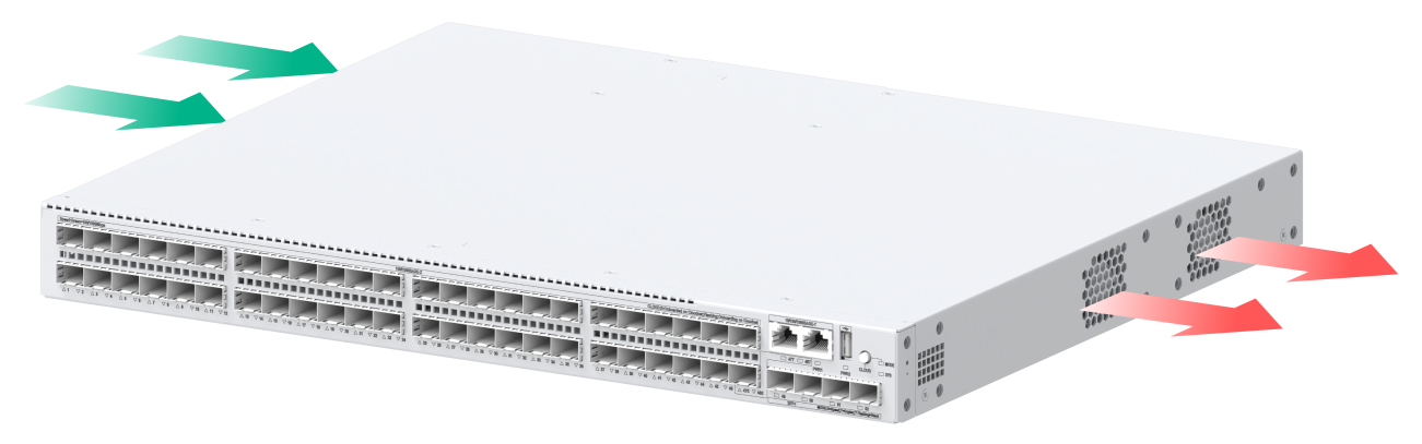
6 Cooling system
To dissipate heat timely and enhance system stability, the switch uses a high-performance cooling system. Consider the site ventilation design when you plan the installation site for the switch.
|
Switch model |
Fan tray type |
Airflow direction |
|
S5135S-8FP4S-EI-Q S5135S-8FP4XS-EI-Q S5135S-8T4XS-EI-Q S5135S-8T4S-EI-Q S5135S-10T2S2X-EI-Q S5135S-16T4S-EI S5135S-16T4X-EI-Q S5135S-24T4S-EI-Q S5135S-24T4X-EI-Q S5135S-48T4S-EI-Q S5135S-48T4X-EI-Q |
Fanless |
Passive cooling |
|
S5135S-16FP4S-EI S5135S-16FP4X-EI S5135S-24FP4S4X-EI S5135S-24FP4T4S-EI S5135S-24P4S-EI S5135S-24P4X-EI S5135S-24S8T4X-EI S5135S-48FP4S-EI S5135S-48FP4X-EI S5135S-48P4S-EI S5135S-48P4X-EI S5135S-48S2T4X-EI S5135S-48ST4X-EI |
Fixed fan trays |
From the left side to the right side |
Figure6-1 Airflow through the S5135S-48S2T4X-EI chassis