- Table of Contents
- Related Documents
-
01-Hardware Information and Specifications
1 Product models and technical specifications
3 Removable components and compatibility matrixes
250W power supplies (PSR250-12A and PSR250-12A1)
180W AC power supplies (PSR180-12A-F and PSR180-12A-B)
180W DC power supply (PSR180-12D-B)
600W power supply (PSR600-54A-B)
920W power supply (PSR920-54A-B)
1600W power supply (PSR1600-54A-B)
10/100/1000BASE-T Ethernet port
10G/5G/2.5G/1000BASE-T autosensing Ethernet port
Ports on an LSWM2EC EPS scanner module
Ports on an LSPM6FWD firewall module
Connecting cables to the ports on expansion cards
10/100/1000BASE-T autosensing Ethernet port LED
10G/5G/2.5G/1000BASE autosensing Ethernet port LED
Fan tray status LED on a fan tray
Status LED on a PSR250-12A/PSR250-12A1 power supply
Status LEDs on a 600W/920W/1600W power supply
LEDs on an LSWM2SP8P/LSWM2SP8PM interface card
LEDs on an LSWM2EC EPS scanner module
1 Product models and technical specifications
Unless otherwise stated, interface modules and interface cards are used interchangeably in this document.
Product models
Table1-1 Switch series and models
|
Model |
Product code (PID) |
||
|
S5590-HI switch series |
Non-PoE models |
S5590-28T8XC-HI |
LS-5590-28T8XC-HI |
|
S5590-48T4XC-HI |
LS-5590-48T4XC-HI |
||
|
S5590-28S8XC-HI |
LS-5590-28S8XC-HI |
||
|
S5590-48S4XC-HI |
LS-5590-48S4XC-HI |
||
|
S5590-EI switch series |
Non-PoE models |
S5590-28T8XC-EI |
LS-5590-28T8XC-EI |
|
LS-5590-28T8XC-EI-GL |
|||
|
LS-5590-28T8XC-EI-H3 |
|||
|
LS-5590-28T8XC-EI-G3 |
|||
|
S5590-48T4XC-EI |
LS-5590-48T4XC-EI |
||
|
LS-5590-48T4XC-EI-GL |
|||
|
LS-5590-48T4XC-EI-H3 |
|||
|
LS-5590-48T4XC-EI-G3 |
|||
|
S5590-28S8XC-EI |
LS-5590-28S8XC-EI |
||
|
LS-5590-28S8XC-EI-GL |
|||
|
S5590-48S4XC-EI |
LS-5590-48S4XC-EI |
||
|
LS-5590-48S4XC-EI-GL |
|||
|
S5590-24X4YC-EI |
LS-S5590-24X4YC-EI |
||
|
S5590-48TS4X2QC-EI |
LS-S5590-48TS4X2QC-EI |
||
|
PoE models |
S5590-28P8XC-EI |
LS-5590-28P8XC-EI |
|
|
LS-5590-28P8XC-EI-GL |
|||
|
LS-5590-28P8XC-EI-G3 |
|||
|
S5590-48P6XC-EI |
LS-5590-48P6XC-EI |
||
|
LS-5590-48P6XC-EI-GL |
|||
|
LS-5590-48P6XC-EI-G3 |
|||
|
S5590-24UXM4YC-EI |
LS-5590-24UXM4YC-EI |
||
|
LS-5590-24UXM4YC-EI-GL |
|||
|
S5590-48UXM4YC-EI |
LS-5590-48UXM4YC-EI |
||
|
LS-5590-48UXM4YC-EI-GL |
|||
|
|
NOTE: · Switches of the same model but different PIDs might differ in hardware and software features. You can view the PID of a switch on the label located on its rear panel or top panel. · To obtain the purchase information, see the product data sheet at https://www.h3c.com/en/Products_and_Solutions/InterConnect/Switches/ and pay attention to the switch product lifecycle management announcement at https://www.h3c.com/en/Support/Policy_Dynamics/Management_Strategy/Products_End_of_Life_Announcement/Switches/. · For information about product and software compatibility, see the release notes. |
Technical specifications
S5590-HI switch series
Table1-2 Technical specifications
|
Item |
S5590-28T8XC-HI |
S5590-48T4XC-HI |
S5590-28S8XC-HI |
S5590-48S4XC-HI |
|
Physical specifications |
||||
|
Dimensions (H × W × D) |
44 × 440 × 400 mm (1.73 × 17.32 × 15.75 in) |
|||
|
Dimensions (H × W × D, with package materials) |
148 × 575 × 520 mm (5.83 × 22.64 × 20.47 in) |
|||
|
Weight (fully configured with power supplies and fan trays) |
≤ 8 kg (17.64 lb) |
|||
|
Technical specifications |
||||
|
Memory (RAM) |
4 GB |
|||
|
Flash |
1 GB |
|||
|
Port types and quantity |
||||
|
Console port |
1 × serial console port |
|||
|
USB port |
1 |
|||
|
Management Ethernet port |
1 |
|||
|
SFP+ port |
8 |
4 |
8 |
4 |
|
SFP port |
4 (Each and its corresponding 10/100/1000BASE-T autosensing Ethernet port form a combo interface.) |
N/A |
28 (The four highest-numbered SFP ports and their corresponding 10/100/1000BASE-T autosensing Ethernet ports form combo interfaces.) |
48 (The four highest-numbered SFP ports cannot be used when the port rate mode of the expansion slots is mode2.) |
|
10/100/1000BASE-T autosensing Ethernet port |
28 (The four highest-numbered 10/100/1000BASE-T autosensing Ethernet ports and their corresponding SFP ports form combo interfaces.) |
48 (The four highest-numbered 10/100/1000BASE-T autosensing Ethernet ports cannot be used when the port rate mode of the expansion slots is mode 2.) |
4 (Each and its corresponding SFP port form a combo interface.) |
N/A |
|
IRF physical ports |
The following ports on the switch panel and expansion cards support IRF connection: · SFP+ ports (The SFP+ ports on the LSWM2SP2PB or LSWM2SP4PB interface module cannot be used as IRF physical ports.) · SFP28 ports · QSFP+ ports · QSFP28 ports 10G, 25G, 40G, and 100G IRF links are supported. |
|||
|
Fan tray, power supply, and expansion card slots |
||||
|
Expansion slot |
2 |
|||
|
Power supply slot |
2 |
|||
|
Fan tray slot |
2 |
|||
|
Power supply specifications |
||||
|
Power input |
AC input |
|||
|
Power specifications |
See "Removable power supplies" |
|||
|
Power consumption |
||||
|
Power consumption (static) Data collection standard: no load |
Single power input: 42 W Dual power inputs: 47 W |
Single power input: 44 W Dual power inputs: 50 W |
Single power input: 43 W Dual power inputs: 49 W |
Single power input: 47 W Dual power inputs: 55 W |
|
Power consumption (typical) Data collection standard: fully configured with copper cables or network cables, at 30% load |
Single power input: 57 W Dual power inputs: 60 W |
Single power input: 67 W Dual power inputs: 70 W |
Single power input: 54 W Dual power inputs: 57 W |
Single power input: 62 W Dual power inputs: 65 W |
|
Power consumption (full load) Data collection standard: fully configured with transceiver modules or network cables, at 100% load |
Single power input: 136 W Dual power inputs: 141 W |
Single power input: 132 W Dual power inputs: 136 W |
Single power input: 138 W Dual power inputs: 142 W |
Single power input: 152 W Dual power inputs: 156 W |
|
Thermal consumption |
||||
|
Thermal consumption (static) Data collection standard: no load |
Single power input: 143 BTU/h Dual power inputs: 160 BTU/h |
Single power input: 150 BTU/h Dual power inputs: 170 BTU/h |
Single power input: 146 BTU/h Dual power inputs: 167 BTU/h |
Single power input: 160 BTU/h Dual power inputs: 187 BTU/h |
|
Thermal consumption (typical) Data collection standard: fully configured with copper cables or network cables, at 30% load |
Single power input: 194 BTU/h Dual power inputs: 204 BTU/h |
Single power input: 228 BTU/h Dual power inputs: 238 BTU/h |
Single power input: 184 BTU/h Dual power inputs: 194 BTU/h |
Single power input: 211 BTU/h Dual power inputs: 221 BTU/h |
|
Thermal consumption (full load) Data collection standard: fully configured with transceiver modules or network cables, at 100% load |
Single power input: 464 BTU/h Dual power inputs: 481 BTU/h |
Single power input: 450 BTU/h Dual power inputs: 464 BTU/h |
Single power input: 470 BTU/h Dual power inputs: 484 BTU/h |
Single power input: 518 BTU/h Dual power inputs: 532 BTU/h |
|
Heat dissipation |
||||
|
Heat dissipation method |
Air cooling |
|||
|
Ventilation aisle |
Front-to-rear or rear-to-front airflow, determined by the selected fan tray model |
|||
|
Reliability and availability |
||||
|
Power supply redundancy |
1+1 |
|||
|
Fan tray redundancy |
You must install two fan trays on the switch. |
|||
|
Hot swapping |
Power supplies and fan trays support hot swapping. Expansion cards support hot swapping, but do not hot swap an expansion card when the switch is starting up |
|||
|
Mean Time Between Failure (MTBF) (year) |
90.99 |
101.63 |
95.79 |
92.43 |
|
Mean time to repair (MTTR) (hour) |
1 |
1 |
1 |
1 |
|
Availability |
99.999876% |
99.999863% |
99.999882% |
99.999879% |
|
Environment specifications |
||||
|
Sound pressure level at 27°C (80.6°F) |
47.6 dB |
49 dB |
48 dB |
48.8 dB |
|
Altitude |
0 m to 5000 m (0 ft to 16404.20 ft) |
|||
|
Operating temperature |
–5°C to +45°C (23°F to 113°F) Note: The allowed maximum temperature decreases by 0.33 °C (32.59°F) as the altitude increases by 100 m (328.08 ft) from 0 m (0 ft). |
|||
|
Storage temperature |
–40°C to +70°C (–40°F to +158°F) |
|||
|
Operating humidity |
5% RH to 95% RH, noncondensing |
|||
|
Compliance |
||||
|
Product compliance |
· Safety standards · EMC standards · Environmental and eco-friendly standards |
|||
S5590-EI switch series
Table1-3 Technical specifications for non-PoE switch models (1)
|
Item |
S5590-28T8XC-EI (LS-5590-28T8XC-EI/LS-5590-28T8XC-EI-G3) |
S5590-28T8XC-EI (LS-5590-28T8XC-EI-GL/LS-5590-28T8XC-EI-H3) |
S5590-48T4XC-EI (LS-5590-48T4XC-EI/LS-5590-48T4XC-EI-G3) |
S5590-48T4XC-EI (LS-5590-48T4XC-EI-GL/LS-5590-48T4XC-EI-H3) |
|
Physical specifications |
||||
|
Dimensions (H × W × D) |
44 × 440 × 360 mm (1.73 × 17.32 × 14.17 in) |
|||
|
Dimensions (H × W × D, with package materials) |
125 × 562 × 550 mm (4.92 × 22.13 × 21.65 in) |
LS-5590-28T8XC-EI-GL: 125 × 580 × 562 mm (4.92 × 22.83 × 22.13 in) LS-5590-28T8XC-EI-H3: 125 × 562 × 550 mm (4.92 × 22.13 × 21.65 in) |
125 × 562 × 550 mm (4.92 × 22.13 × 21.65 in) |
LS-5590-48T4XC-EI-GL: 125 × 580 × 562 mm (4.92 × 22.83 × 22.13 in) LS-5590-48T4XC-EI-H3: 125 × 562 × 550 mm (4.92 × 22.13 × 21.65 in) |
|
Weight (fully configured with power supplies and fan trays) |
≤ 7 kg (15.43 lb) |
|||
|
Technical specifications |
||||
|
Memory (RAM) |
2 GB |
|||
|
Flash |
4 GB |
|||
|
Port types and quantity |
||||
|
Console port |
1 × serial console port |
|||
|
USB port |
1 |
|||
|
Management Ethernet port |
1 |
|||
|
SFP+ port |
8 |
8 |
4 |
4 |
|
SFP port |
4 (Each and its corresponding 10/100/1000BASE-T autosensing Ethernet port form a combo interface.) |
4 (Each and its corresponding 10/100/1000BASE-T autosensing Ethernet port form a combo interface.) |
N/A |
N/A |
|
10/100/1000BASE-T autosensing Ethernet port |
28 (The four highest-numbered 10/100/1000BASE-T autosensing Ethernet ports and their corresponding SFP ports form combo interfaces.) |
28 (The four highest-numbered 10/100/1000BASE-T autosensing Ethernet ports and their corresponding SFP ports form combo interfaces.) |
48 |
48 |
|
IRF physical ports |
The following ports on the switch panel and expansion cards support IRF connection: · SFP+ ports (The SFP+ ports on the LSWM2SP2PB or LSWM2SP4PB interface module cannot be used as IRF physical ports.) · SFP28 ports · QSFP+ ports · QSFP28 ports 10G, 25G, 40G, and 100G IRF links are supported. |
|||
|
Fan tray, power supply, and expansion card slots |
||||
|
Expansion slot |
1 |
|||
|
Power supply slot |
2 |
|||
|
Fan tray slot |
2 |
|||
|
Power supply specifications |
||||
|
Power input |
AC input, DC input Note: The S5590-EI switch series does not support HVDC input. For DC input, you can use a –48 VDC power source in the equipment room or an RPS (H3C RPS1600-A). |
|||
|
Power specifications |
See "Removable power supplies" |
|||
|
Power consumption |
||||
|
Power consumption (static) Data collection standard: no load |
Single power input: 38 W Dual power inputs: 45 W |
Single power input: 39 W Dual power inputs: 46 W |
Single power input: 41 W Dual power inputs: 48 W |
Single power input: 42 W Dual power inputs: 48 W |
|
Power consumption (typical) Data collection standard: fully configured with copper cables or network cables, at 30% load |
N/A |
Single power input: 52 W Dual power inputs: 58 W |
N/A |
Single power input: 65 W Dual power inputs: 70 W |
|
Power consumption (full load) Data collection standard: fully configured with transceiver modules or network cables, at 100% load |
Single power input: 108 W Dual power inputs: 114 W |
Single power input: 110 W Dual power inputs: 115 W |
Single power input: 105 W Dual power inputs: 108 W |
Single power input: 115 W Dual power inputs: 120 W |
|
Thermal consumption |
||||
|
Thermal consumption (static) Data collection standard: no load |
Single power input: 129 BTU/h Dual power inputs: 153 BTU/h |
N/A |
Single power input: 139 BTU/h Dual power inputs: 163 BTU/h |
N/A |
|
Thermal consumption (typical) Data collection standard: fully configured with copper cables or network cables, at 30% load |
Single power input: 191 BTU/h Dual power inputs: 201 BTU/h |
N/A |
Single power input: 221 BTU/h Dual power inputs: 232 BTU/h |
N/A |
|
Thermal consumption (full load) Data collection standard: fully configured with transceiver modules or network cables, at 100% load |
Single power input: 368 BTU/h Dual power inputs: 388 BTU/h |
N/A |
Single power input: 358 BTU/h Dual power inputs: 368 BTU/h |
N/A |
|
Heat dissipation |
||||
|
Heat dissipation method |
Air cooling |
|||
|
Ventilation aisle |
Front-to-rear or rear-to-front airflow, determined by the selected fan tray model |
|||
|
Reliability and availability |
||||
|
Power supply redundancy |
1+1 |
|||
|
Fan tray redundancy |
You must install two fan trays on the switch. |
|||
|
Hot swapping |
Power supplies and fan trays support hot swapping. Expansion cards support hot swapping, but do not hot swap an expansion card when the switch is starting up |
|||
|
Mean Time Between Failure (MTBF) (year) |
105.15 |
105.15 |
101.63 |
101.63 |
|
Mean time to repair (MTTR) (hour) |
1 |
1 |
1 |
1 |
|
Availability |
99.999893% |
99.999893% |
99.999888% |
99.999888% |
|
Environment specifications |
||||
|
Sound pressure level at 27°C (80.6°F) |
49 dB |
49 dB |
46.6 dB |
46.6 dB |
|
Altitude |
0 m to 5000 m (0 ft to 16404.20 ft) |
|||
|
Operating temperature |
–5°C to +45°C (23°F to 113°F) Note: The allowed maximum temperature decreases by 0.33 °C (32.59°F) as the altitude increases by 100 m (328.08 ft) from 0 m (0 ft). |
|||
|
Storage temperature |
–40°C to +70°C (–40°F to +158°F) |
|||
|
Operating humidity |
5% RH to 95% RH, noncondensing |
|||
|
Compliance |
||||
|
Product compliance |
· Safety standards · EMC standards · Environmental and eco-friendly standards |
|||
Table1-4 Technical specifications for non-PoE switch models (2)
|
Item |
S5590-24X4YC-EI |
S5590-48TS4X2QC-EI |
S5590-28S8XC-EI (LS-5590-28S8XC-EI-GL/LS-5590-28S8XC-EI) |
S5590-48S4XC-EI (LS-5590-48S4XC-EI-GL/LS-5590-48S4XC-EI) |
|
Physical specifications |
||||
|
Dimensions (H × W × D) |
44 × 440 × 360 mm (1.73 × 17.32 × 14.17 in) |
|||
|
Dimensions (H × W × D, with package materials) |
125 × 580 × 562 mm (4.92 × 22.83 × 22.13 in) |
125 × 580 × 562 mm (4.92 × 22.83 × 22.13 in) |
LS-5590-28S8XC-EI-GL: 125 × 580 × 562 mm (4.92 × 22.83 × 22.13 in) LS-5590-28S8XC-EI: 125 × 562 × 550 mm (4.92 × 22.13 × 21.65 in) |
LS-5590-48S4XC-EI-GL: 125 × 580 × 562 mm (4.92 × 22.83 × 22.13 in) LS-5590-48S4XC-EI: 125 × 562 × 550 mm (4.92 × 22.13 × 21.65 in) |
|
Weight (fully configured with power supplies and fan trays) |
≤ 7 kg (15.43 lb) |
|||
|
Technical specifications |
||||
|
Memory (RAM) |
2 GB |
2 GB |
2 GB |
2 GB |
|
Flash |
8 GB |
8 GB |
4 GB |
4 GB |
|
Port types and quantity |
||||
|
Console port |
1 × serial console port |
|||
|
USB port |
1 |
|||
|
Management Ethernet port |
1 |
|||
|
SFP+ port |
24 |
4 |
8 |
4 |
|
SFP port |
N/A |
24 |
28 (The four highest-numbered SFP ports and their corresponding 10/100/1000BASE-T autosensing Ethernet ports form combo interfaces.) |
48 |
|
SFP28 port |
4 |
N/A |
N/A |
N/A |
|
QSFP+ port |
N/A |
2 |
N/A |
N/A |
|
10/100/1000BASE-T autosensing Ethernet port |
N/A |
24 |
4 (Each and its corresponding SFP port form a combo interface.) |
N/A |
|
IRF physical ports |
The following ports on the switch panel and expansion cards support IRF connection: · SFP+ ports (The SFP+ ports on the LSWM2SP2PB or LSWM2SP4PB interface module cannot be used as IRF physical ports.) · SFP28 ports · QSFP+ ports · QSFP28 ports 10G, 25G, 40G, and 100G IRF links are supported. |
|||
|
Fan tray, power supply, and expansion card slots |
||||
|
Expansion slot |
1 |
|||
|
Power supply slot |
2 |
|||
|
Fan tray slot |
2 |
|||
|
Power supply specifications |
||||
|
Power input |
AC input, DC input Note: The S5590-EI switch series does not support HVDC input. For DC input, you can use a –48 VDC power source in the equipment room or an RPS (H3C RPS1600-A). |
|||
|
Power specifications |
See "Removable power supplies" |
|||
|
Power consumption |
||||
|
Power consumption (static) Data collection standard: no load |
Single AC input: 30 W Dual AC inputs: 37 W Single DC input: 29 W Dual DC inputs: 36 W |
Single AC input: 40 W Dual AC inputs: 43 W Single DC input: 34 W Dual DC inputs: 42 W |
Single power input: 39 W Dual power inputs: 46 W |
Single power input: 42 W Dual power inputs: 49 W |
|
Power consumption (typical) Data collection standard: fully configured with copper cables or network cables, at 30% load |
Single AC input: 40 W Dual AC inputs: 47 W Single DC input: 39 W Dual DC inputs: 46 W |
Single AC input: 56 W Dual AC inputs: 64 W Single DC input: 57 W Dual DC inputs: 64 W |
Single power input: 43 W Dual power inputs: 50 W |
Single power input: 48 W Dual power inputs: 53 W |
|
Power consumption (full load) Data collection standard: fully configured with transceiver modules or network cables, at 100% load |
Single AC input: 95 W Dual AC inputs: 102 W Single DC input: 93 W Dual DC inputs: 98 W |
Single AC input: 120 W Dual AC inputs: 125 W Single DC input: 120 W Dual DC inputs: 125 W |
Single power input: 119 W Dual power inputs: 123 W |
Single power input: 137 W Dual power inputs: 142 W |
|
Thermal consumption |
||||
|
Thermal consumption (static) Data collection standard: no load |
N/A |
N/A |
Single power input: 133 BTU/h Dual power inputs: 156 BTU/h |
Single power input: 143 BTU/h Dual power inputs: 167 BTU/h |
|
Thermal consumption (typical) Data collection standard: fully configured with copper cables or network cables, at 30% load |
N/A |
N/A |
Single power input: 170 BTU/h Dual power inputs: 180 BTU/h |
Single power input: 177 BTU/h Dual power inputs: 187 BTU/h |
|
Thermal consumption (full load) Data collection standard: fully configured with transceiver modules or network cables, at 100% load |
N/A |
N/A |
Single power input: 406 BTU/h Dual power inputs: 419 BTU/h |
Single power input: 467 BTU/h Dual power inputs: 484 BTU/h |
|
Heat dissipation |
||||
|
Heat dissipation method |
Air cooling |
|||
|
Ventilation aisle |
Front-to-rear or rear-to-front airflow, determined by the selected fan tray model |
|||
|
Reliability and availability |
||||
|
Power supply redundancy |
1+1 |
|||
|
Fan tray redundancy |
You must install two fan trays on the switch. |
|||
|
Hot swapping |
Power supplies and fan trays support hot swapping. Expansion cards support hot swapping, but do not hot swap an expansion card when the switch is starting up |
|||
|
Mean Time Between Failure (MTBF) (year) |
238.58 |
162.05 |
101.74 |
101.01 |
|
Mean time to repair (MTTR) (hour) |
1 |
1 |
1 |
1 |
|
Availability |
N/A |
N/A |
99.999898% |
99.999885% |
|
Environment specifications |
||||
|
Sound pressure level at 27°C (80.6°F) |
40.9 dB |
40.9 dB |
46.6 dB |
47.4 dB |
|
Altitude |
0 m to 5000 m (0 ft to 16404.20 ft) |
|||
|
Operating temperature |
–5°C to +45°C (23°F to 113°F) Note: The allowed maximum temperature decreases by 0.33 °C (32.59°F) as the altitude increases by 100 m (328.08 ft) from 0 m (0 ft). |
|||
|
Storage temperature |
–40°C to +70°C (–40°F to +158°F) |
|||
|
Relative humidity |
5% RH to 95% RH, noncondensing |
|||
|
Compliance |
||||
|
Product compliance |
· Safety standards · EMC standards · Environmental and eco-friendly standards |
|||
Table1-5 Technical specifications for PoE switch models (1)
|
Item |
S5590-28P8XC-EI |
S5590-48P6XC-EI |
|
Physical specifications |
||
|
Dimensions (H × W × D) |
44 × 440 × 400 mm (1.73 × 17.32 × 15.75 in) |
|
|
Dimensions (H × W × D, with package materials) |
150 × 556 × 528 mm (5.91 × 21.89 × 20.79 in) |
|
|
Weight (fully configured with power supplies and fan trays) |
≤ 7 kg (15.43 lb) |
|
|
Technical specifications |
||
|
Memory (RAM) |
2 GB |
|
|
Flash |
4 GB |
|
|
Port types and quantity |
||
|
Console port |
1 × serial console port |
|
|
USB port |
1 |
|
|
Management Ethernet port |
1 |
|
|
SFP+ port |
8 |
6 |
|
SFP port |
4 (Each and its corresponding 10/100/1000BASE-T autosensing Ethernet port form a combo interface.) |
N/A |
|
10/100/1000BASE-T autosensing Ethernet port |
28 (The four highest-numbered 10/100/1000BASE-T autosensing Ethernet ports and their corresponding SFP ports form combo interfaces.) |
48 |
|
IRF physical ports |
The following ports on the switch panel and expansion cards support IRF connection: · SFP+ ports (The SFP+ ports on the LSWM2SP2PB or LSWM2SP4PB interface module cannot be used as IRF physical ports.) · SFP28 ports · QSFP+ ports · QSFP28 ports 10G, 25G, 40G, and 100G IRF links are supported. |
|
|
Fan tray, power supply, and expansion card slots |
||
|
Expansion slot |
1 |
|
|
Power supply slot |
2 |
|
|
Fan tray slot |
2 |
|
|
Power supply specifications |
||
|
Power input |
AC input |
|
|
Power specifications |
See "Removable power supplies" |
|
|
PoE power capacity |
||
|
Max PoE power capacity per port |
30 W or 35 W Note: The maximum PoE power capacity per port varies by software version. For more information about the maximum PoE power capacity per port, see the software release for the product or verify it on the switch. |
|
|
Total PoE power capacity |
See Table1-9 |
|
|
Power consumption |
||
|
Power consumption (static) Data collection standard: no load |
Single power input: 48 W Dual power inputs: 53 W |
Single power input: 52 W Dual power inputs: 59 W |
|
Power consumption (typical) Data collection standard: fully configured with copper cables or network cables, at 30% load |
Single power input: 48 W Dual power inputs: 53 W |
Single power input: 73 W Dual power inputs: 86 W |
|
Power consumption (full load) Data collection standard: fully configured with transceiver modules or network cables, at 100% load |
Single power input: 938 W Dual power inputs: 1046 W |
Single power input: 945 W Dual power inputs: 1745 W |
|
Thermal consumption |
||
|
Thermal consumption (static) Data collection standard: no load |
Single power input: 164 BTU/h Dual power inputs: 181 BTU/h |
Single power input: 177 BTU/h Dual power inputs: 201 BTU/h |
|
Thermal consumption (typical) Data collection standard: fully configured with copper cables or network cables, at 30% load |
Single power input: 192 BTU/h Dual power inputs: 225 BTU/h |
Single power input: 246 BTU/h Dual power inputs: 287 BTU/h |
|
Thermal consumption (full load) Data collection standard: fully configured with transceiver modules or network cables, at 100% load |
Single power input: 3200 BTU/h Dual power inputs: 3569 BTU/h |
Single power input: 3224 BTU/h Dual power inputs: 5956 BTU/h |
|
Heat dissipation |
||
|
Heat dissipation method |
Air cooling |
|
|
Ventilation aisle |
Front-to-rear or rear-to-front airflow, determined by the selected fan tray model |
|
|
Reliability and availability |
||
|
Power supply redundancy |
1+1 |
|
|
Fan tray redundancy |
You must install two fan trays on the switch. |
|
|
Hot swapping |
Power supplies and fan trays support hot swapping. Expansion cards support hot swapping, but do not hot swap an expansion card when the switch is starting up |
|
|
Mean Time Between Failure (MTBF) (year) |
32.15/55.18 |
28.62/55.18 |
|
Mean time to repair (MTTR) (hour) |
1 |
1 |
|
Availability |
99.999653% |
99.999612% |
|
Environment specifications |
||
|
Sound pressure level at 27°C (80.6°F) |
48.6 dB |
62.8 dB |
|
Altitude |
0 m to 5000 m (0 ft to 16404.20 ft) |
|
|
Operating temperature |
–5°C to +45°C (23°F to 113°F) Note: The allowed maximum temperature decreases by 0.33 °C (32.59°F) as the altitude increases by 100 m (328.08 ft) from 0 m (0 ft). |
|
|
Storage temperature |
–40°C to +70°C (–40°F to +158°F) |
|
|
Relative humidity |
5% RH to 95% RH, noncondensing |
|
|
Compliance |
||
|
Product compliance |
· Safety standards · EMC standards · Environmental and eco-friendly standards |
|
Table1-6 Technical specifications for PoE switch models (2)
|
Item |
S5590-24UXM4YC-EI |
S5590-48UXM4YC-EI |
|
Physical specifications |
||
|
Dimensions (H × W × D) |
44 × 440 × 400 mm (1.73 × 17.32 × 15.75 in) |
|
|
Dimensions (H × W × D, with package materials) |
180 × 678 × 576 mm (7.09 × 26.69 × 22.68 in) |
|
|
Weight (fully configured with power supplies and fan trays) |
≤ 9.5 kg (20.94 lb) |
|
|
Technical specifications |
||
|
Memory (RAM) |
2 GB |
|
|
Flash |
8 GB |
|
|
Port types and quantity |
||
|
Console port |
1 × serial console port |
|
|
USB port |
1 |
|
|
Management Ethernet port |
1 |
|
|
SFP28 port |
4 |
4 |
|
10/100/1000BASE-T autosensing Ethernet port |
16 |
32 |
|
10G/5G/2.5G/1000/100/10BASE-T autosensing Ethernet port |
8 |
16 |
|
IRF physical ports |
The following ports on the switch panel and expansion cards support IRF connection: · SFP+ ports (The SFP+ ports on the LSWM2SP2PB or LSWM2SP4PB interface module cannot be used as IRF physical ports.) · SFP28 ports · QSFP+ ports · QSFP28 ports 10G, 25G, 40G, and 100G IRF links are supported. |
|
|
Fan tray, power supply, and expansion card slots |
||
|
Expansion slot |
1 |
|
|
Power supply slot |
2 |
|
|
Fan tray slot |
2 |
|
|
Power supply specifications |
||
|
Power input |
AC input |
|
|
Power specifications |
See "Removable power supplies" |
|
|
PoE power capacity |
||
|
Max PoE power capacity per port |
100 W |
|
|
Total PoE power capacity |
See Table1-9 |
|
|
Power consumption |
||
|
Power consumption (static) Data collection standard: no load |
Single power input: 56 W Dual power inputs: 66 W |
Single power input: 63 W Dual power inputs: 74 W |
|
Power consumption (typical) Data collection standard: fully configured with copper cables or network cables, at 30% load |
Single power input: 82 W Dual power inputs: 90 W |
Single power input: 110 W Dual power inputs: 125 W |
|
Power consumption (full load) Data collection standard: fully configured with transceiver modules or network cables, at 100% load |
See Table1-7 |
|
|
Thermal consumption |
||
|
Thermal consumption (static) Data collection standard: no load |
Single power input: 191 BTU/h Dual power inputs: 225 BTU/h |
Single power input: 214 BTU/h Dual power inputs: 252 BTU/h |
|
Thermal consumption (typical) Data collection standard: fully configured with copper cables or network cables, at 30% load |
Single power input: 279 BTU/h Dual power inputs: 307 BTU/h |
Single power input: 375 BTU/h Dual power inputs: 427 BTU/h |
|
Thermal consumption (full load) Data collection standard: fully configured with transceiver modules or network cables, at 100% load |
See Table1-8 |
|
|
Heat dissipation |
||
|
Heat dissipation method |
Air cooling |
|
|
Ventilation aisle |
Port-to-power supply airflow |
|
|
Reliability and availability |
||
|
Power supply redundancy |
1+1 |
|
|
Fan tray redundancy |
You must install two fan trays on the switch. |
|
|
Hot swapping |
Power supplies and fan trays support hot swapping. Expansion cards support hot swapping, but do not hot swap an expansion card when the switch is starting up |
|
|
Mean Time Between Failure (MTBF) (year) |
72.5 |
68.97 |
|
Mean time to repair (MTTR) (hour) |
1 |
1 |
|
Availability |
99.99984% |
99.999832% |
|
Environment specifications |
||
|
Sound pressure level at 27°C (80.6°F) |
47.9 dB |
47.9 dB |
|
Altitude |
0 m to 5000 m (0 ft to 16404.20 ft) |
|
|
Operating temperature |
–5°C to +45°C (23°F to 113°F) Note: The allowed maximum temperature decreases by 0.33 °C (32.59°F) as the altitude increases by 100 m (328.08 ft) from 0 m (0 ft). |
|
|
Storage temperature |
–40°C to +70°C (–40°F to +158°F) |
|
|
Operating humidity |
5% RH to 95% RH, noncondensing |
|
|
Compliance |
||
|
Product compliance |
· Safety standards · EMC standards · Environmental and eco-friendly standards |
|
Table1-7 Power consumption for the S5590-24UXM4YC-EI and S5590-48UXM4YC-EI switches (full load)
|
Power supply configuration |
S5590-24UXM4YC-EI |
S5590-48UXM4YC-EI |
|
1 × PSR600-54A-B |
530 W |
550 W |
|
1 × PSR920-54A-B |
870 W |
910 W |
|
1 × PSR1600-54A-B (90 VAC to 176 VAC) |
925 W |
954 W |
|
1 × PSR1600-54A-B (176 VAC to 290 VAC) |
1630 W |
1645 W |
|
2 × PSR600-54A-B |
1160 W |
1780 W |
|
2 × PSR920-54A-B |
1765 W |
1800 W |
|
2 × PSR1600-54A-B (90 VAC to 176 VAC) |
2020 W |
1982 W |
|
2 × PSR1600-54A-B (176 VAC to 290 VAC) |
2660 W |
3152 W |
Table1-8 Thermal consumption for the S5590-24UXM4YC-EI and S5590-48UXM4YC-EI switches (full load)
|
Power supply configuration |
S5590-24UXM4YC-EI |
S5590-48UXM4YC-EI |
|
1 × PSR600-54A-B |
1808 BTU/h |
1877 BTU/h |
|
1 × PSR920-54A-B |
2969 BTU/h |
3105 BTU/h |
|
1 × PSR1600-54A-B (90 VAC to 176 VAC) |
3156 BTU/h |
3255 BTU/h |
|
1 × PSR1600-54A-B (176 VAC to 290 VAC) |
5562 BTU/h |
5613 BTU/h |
|
2 × PSR600-54A-B |
3958 BTU/h |
6074 BTU/h |
|
2 × PSR920-54A-B |
6022 BTU/h |
6142 BTU/h |
|
2 × PSR1600-54A-B (90 VAC to 176 VAC) |
6893 BTU/h |
6762 BTU/h |
|
2 × PSR1600-54A-B (176 VAC to 290 VAC) |
9076 BTU/h |
10755 BTU/h |
Table1-9 PoE power capacity of the S5590-EI switch series
|
Power supply configuration |
S5590-28P8XC-EI |
S5590-48P6XC-EI |
S5590-24UXM4YC-EI |
S5590-48UXM4YC-EI |
||||
|
Total PoE power capacity |
Max PoE power capacity per port |
Total PoE power capacity |
Max PoE power capacity per port |
Total PoE power capacity |
Max PoE power capacity per port |
Total PoE power capacity |
Max PoE power capacity per port |
|
|
1 × PSR600-54A-B |
450 W |
30 W |
450 W |
30 W |
400 W |
100 W |
400 W |
100 W |
|
1 × PSR920-54A-B |
770 W |
30 W |
770 W |
30 W |
720 W |
100 W |
720 W |
100 W |
|
1 × PSR1600-54A-B (input voltage: 90 VAC to 176 VAC) |
770 W |
30 W |
770 W |
30 W |
720 W |
100 W |
720 W |
100 W |
|
1 × PSR1600-54A-B (input voltage: 176 VAC to 290 VAC or 180 VDC to 320 VDC) |
1000 W |
30 W |
1450 W |
30 W |
1400 W |
100 W |
1400 W |
100 W |
|
2 × PSR600-54A-B |
1000 W |
30 W |
1020 W |
30 W |
970 W |
100 W |
970 W |
100 W |
|
1 × PSR600-54A-B and 1 × PSR920-54A-B |
1000 W |
30 W |
1020 W |
30 W |
970 W |
100 W |
970 W |
100 W |
|
1 × PSR920-54A-B and 1 × PSR1600-54A-B (input voltage: 90 VAC to 176 VAC) |
1000 W |
30 W |
1260 W |
30 W |
1210 W |
100 W |
1210 W |
100 W |
|
1 × PSR920-54A-B and 1 × PSR1600-54A-B (input voltage: 176 VAC to 290 VAC or 180 VDC to 320 VDC) |
1000 W |
30 W |
1600 W |
30 W |
1550 W |
100 W |
1550 W |
100 W |
|
1 × PSR1600-54A-B (input voltage: 90 VAC to 176 VAC) and 1 × PSR1600-54A-B (input voltage: 176 VAC to 1290 VAC or 180 VDC to 320 VDC) |
1000 W |
30 W |
1600 W |
30 W |
1550 W |
100 W |
1550 W |
100 W |
|
2 × PSR920-54A-B |
1000 W |
30 W |
1600 W |
30 W |
1550 W |
100 W |
1550 W |
100 W |
|
2 × PSR1600-54A-B (input voltage: 90 VAC to 176 VAC) |
1000 W |
30 W |
1600 W |
30 W |
1600 W |
100 W |
1600 W |
100 W |
|
2 × PSR1600-54A-B (input voltage: 176 VAC to 1290 VAC or 180 VDC to 320 VDC) |
1000 W |
30 W |
1680 W |
30 W |
2400 W |
100 W |
2800 W |
100 W |
2 Chassis views
S5590-HI switch series
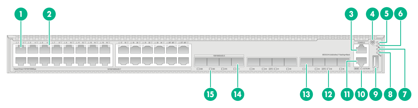
S5590-28T8XC-HI
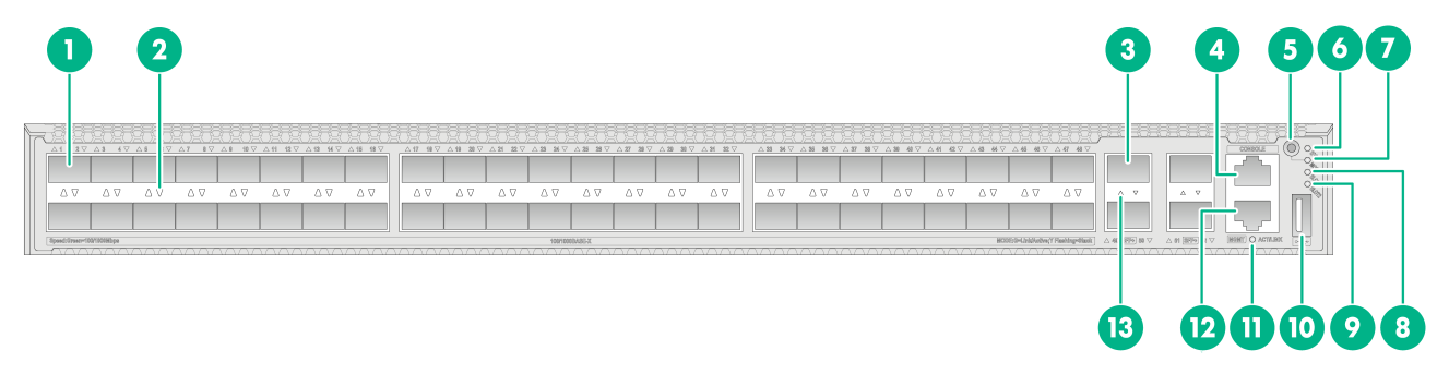
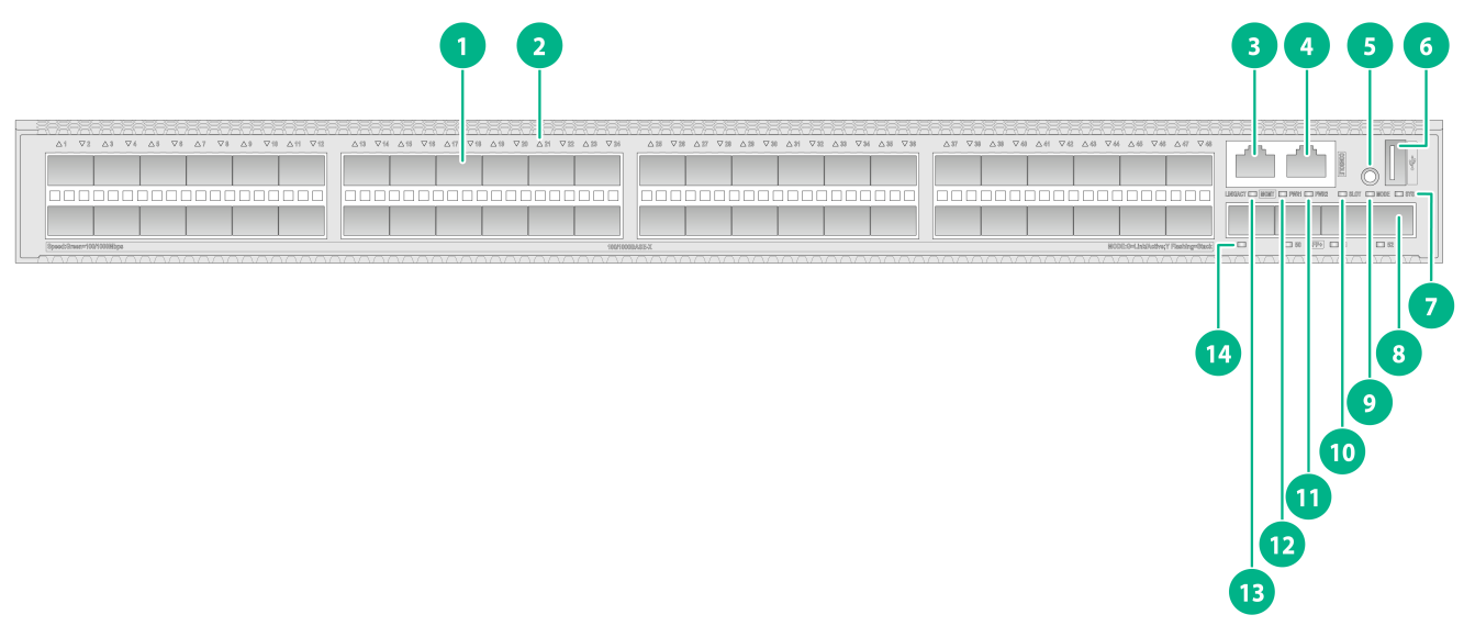
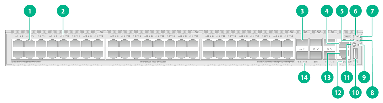
Figure2-1 Front panel
|
(1) 10/100/1000BASE-T autosensing Ethernet port |
(2) 10/100/1000BASE-T autosensing Ethernet port LED |
|
(3) Console port (CONSOLE) |
(4) Mode button |
|
(5) System status LED (SYS) |
(6) Mode LED (MODE) |
|
(7) Expansion card status LED 1 (SLOT1) |
(8) Expansion card status LED 2 (SLOT2) |
|
(9) USB port |
(10) Management Ethernet port LED (ACT/LINK) |
|
(11) Management Ethernet port (MGMT) |
(12) SFP+ port LED |
|
(13) SFP+ port |
(14) SFP port |
|
(15) SFP port LED |
|

|
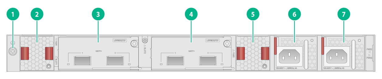
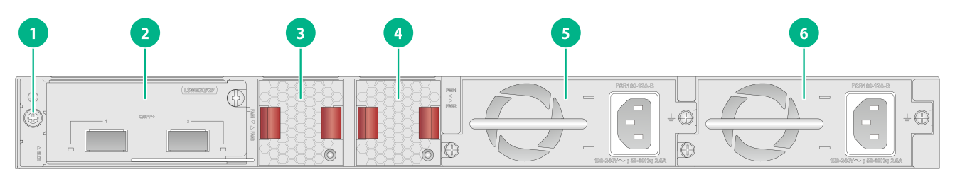
(1) Grounding screw |
(2) Fan tray 1 |
|
(3) Expansion card 1 |
(4) Expansion card 2 |
|
(5) Fan tray 2 |
(6) Power supply 1 |
|
(7) Power supply 2 |
|
The S5590-28T8XC-HI switch came with power supply slot 1 empty and power supply slot 2 installed with a filler panel. You can install one or two power supplies for the switch as required. In Figure2-2, two PSR250-12A1 AC power supplies are installed in the power supply slots.
The S5590-28T8XC-HI switch came with two fan tray slots empty. You must install two fan trays of the same model for the switch. In Figure2-2, two LSPM1FANSB-SN fan trays are installed in the fan tray slots.
The S5590-28T8XC-HI switch came with two expansion slots each installed with a filler panel. You can select expansion cards for the switch as required. In Figure2-2, two LSWM2QP2P interface cards are installed in the expansion slots.
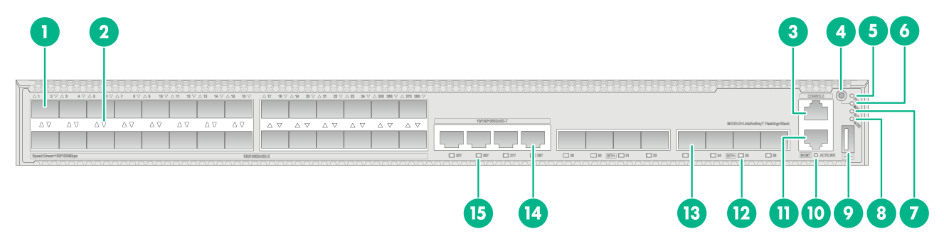
S5590-48T4XC-HI
Figure2-3 Front panel

|
(1) 10/100/1000BASE-T autosensing Ethernet port |
(2) 10/100/1000BASE-T autosensing Ethernet port LED |
|
(3) SFP+ port |
(4) Console port (CONSOLE) |
|
(5) Mode button |
(6) System status LED (SYS) |
|
(7) Mode LED (MODE) |
(8) Expansion card status LED 1 (SLOT1) |
|
(9) Expansion card status LED 2 (SLOT2) |
(10) USB port |
|
(11) Management Ethernet port LED (ACT/LINK) |
(12) Management Ethernet port (MGMT) |
|
(13) SFP+ port LED |
|
|
(1) Grounding screw |
(2) Fan tray 1 |
|
(3) Expansion card 1 |
(4) Expansion card 2 |
|
(5) Fan tray 2 |
(6) Power supply 1 |
|
(7) Power supply 2 |
|
The S5590-48T4XC-HI switch came with power supply slot 1 empty and power supply slot 2 installed with a filler panel. You can install one or two power supplies for the switch as required. In Figure2-4, two PSR250-12A1 AC power supplies are installed in the power supply slots.
The S5590-48T4XC-HI switch came with two fan tray slots empty. You must install two fan trays of the same model for the switch. In Figure2-4, two LSPM1FANSB-SN fan trays are installed in the fan tray slots.
The S5590-48T4XC-HI switch came with two expansion slots each installed with a filler panel. You can select expansion cards for the switch as required. In Figure2-4, two LSWM2QP2P interface cards are installed in the expansion slots.
S5590-28S8XC-HI
Figure2-5 Front panel
|
(1) SFP port |
(2) SFP port LED |
|
(3) Console port (CONSOLE) |
(4) Mode button |
|
(5) System status LED (SYS) |
(6) Mode LED (MODE) |
|
(7) Expansion card status LED 1 (SLOT1) |
(8) Expansion card status LED 2 (SLOT2) |
|
(9) USB port |
(10) Management Ethernet port LED (ACT/LINK) |
|
(11) Management Ethernet port (MGMT) |
(12) SFP+ port LED |
|
(13) SFP+ port |
(14) 10/100/1000BASE-T autosensing Ethernet port |
|
(15) 10/100/1000BASE-T autosensing Ethernet port LED |
|

|
(1) Grounding screw |
(2) Fan tray 1 |
|
(3) Expansion card 1 |
(4) Expansion card 2 |
|
(5) Fan tray 2 |
(6) Power supply 1 |
|
(7) Power supply 2 |
|
The S5590-28S8XC-HI switch came with power supply slot 1 empty and power supply slot 2 installed with a filler panel. You can install one or two power supplies for the switch as required. In Figure2-6, two PSR250-12A1 AC power supplies are installed in the power supply slots.
The S5590-28S8XC-HI switch came with two fan tray slots empty. You must install two fan trays of the same model for the switch. In Figure2-6, two LSPM1FANSB-SN fan trays are installed in the fan tray slots.
The S5590-28S8XC-HI switch came with two expansion slots each installed with a filler panel. You can select expansion cards for the switch as required. In Figure2-6, two LSWM2QP2P interface cards are installed in the expansion slots.
S5590-48S4XC-HI
Figure2-7 Front panel
|
(1) SFP port |
(2) SFP port LED |
|
(3) SFP+ port |
(4) Console port (CONSOLE) |
|
(5) Mode button |
(6) System status LED (SYS) |
|
(7) Mode LED (MODE) |
(8) Expansion card status LED 1 (SLOT1) |
|
(9) Expansion card status LED 2 (SLOT2) |
(10) USB port |
|
(11) Management Ethernet port LED (ACT/LINK) |
(12) Management Ethernet port (MGMT) |
|
(13) SFP+ port LED |
|

|
(1) Grounding screw |
(2) Fan tray 1 |
|
(3) Expansion card 1 |
(4) Expansion card 2 |
|
(5) Fan tray 2 |
(6) Power supply 1 |
|
(7) Power supply 2 |
|
The S5590-48S4XC-HI switch came with power supply slot 1 empty and power supply slot 2 installed with a filler panel. You can install one or two power supplies for the switch as required. In Figure2-8, two PSR250-12A1 AC power supplies are installed in the power supply slots.
The S5590-48S4XC-HI switch came with two fan tray slots empty. You must install two fan trays of the same model for the switch. In Figure2-8, two LSPM1FANSB-SN fan trays are installed in the fan tray slots.
The S5590-48S4XC-HI switch came with two expansion slots each installed with a filler panel. You can select expansion cards for the switch as required. In Figure2-8, two LSWM2QP2P interface cards are installed in the expansion slots.
S5590-EI switch series
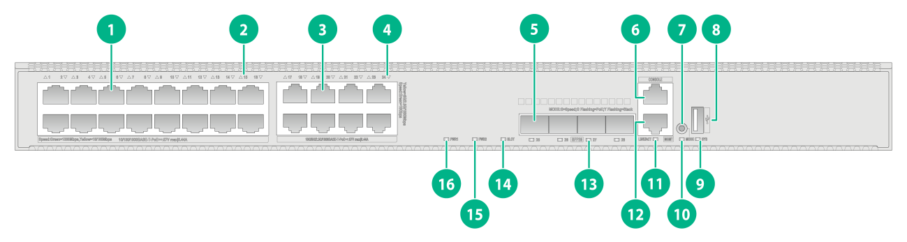
S5590-28T8XC-EI
Figure2-9 Front panel
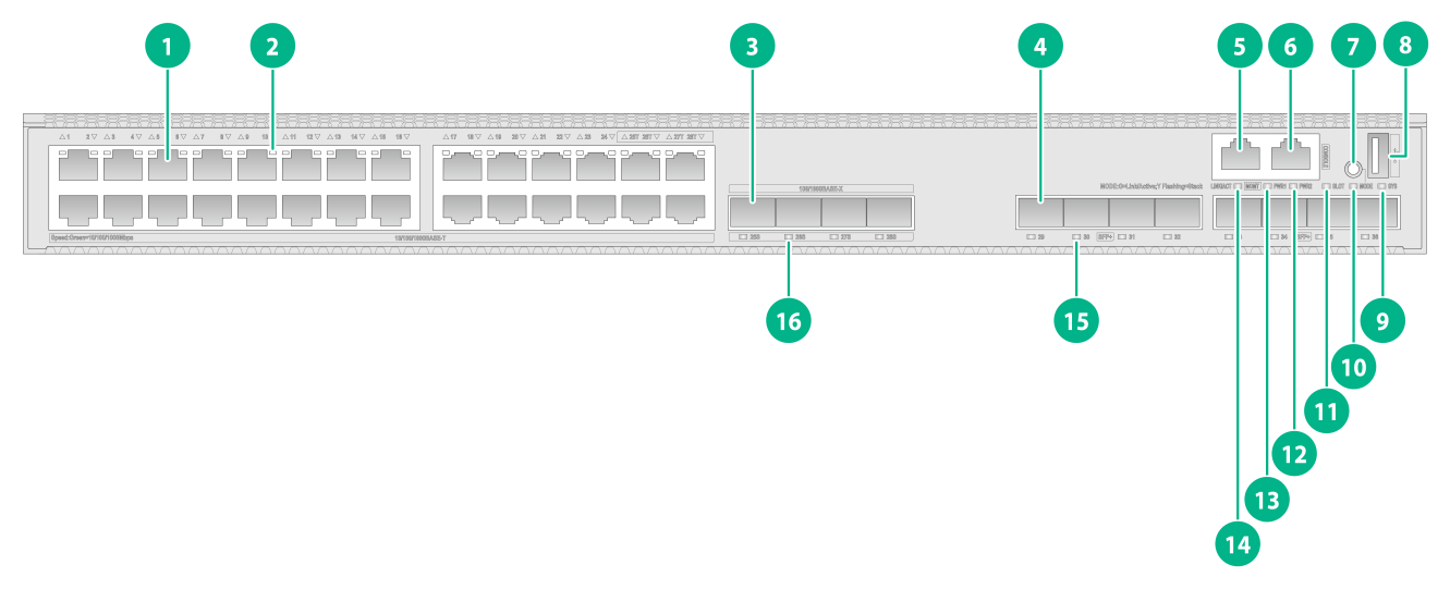
|
(1) 10/100/1000BASE-T autosensing Ethernet port |
(2) 10/100/1000BASE-T autosensing Ethernet port LED |
|
(3) SFP port |
(4) SFP+ port |
|
(5) Management Ethernet port (MGMT) |
(6) Console port (CONSOLE) |
|
(7) Mode button |
(8) USB port |
|
(9) System status LED (SYS) |
(10) Mode LED (MODE) |
|
(11) Expansion card status LED (SLOT) |
(12) Power supply 2 status LED (PWR2) |
|
(13) Power supply 1 status LED (PWR1) |
(14) Management Ethernet port LED (ACT/LINK) |
|
(15) SFP+ port LED |
(16) SFP port LED |

|
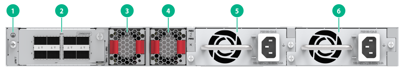
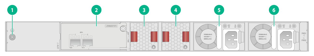
(1) Grounding screw |
(2) Expansion card |
|
(3) Fan tray 1 |
(4) Fan tray 2 |
|
(5) Power supply 1 |
(6) Power supply 2 |
The S5590-28T8XC-EI switch came with power supply slot 1 empty and power supply slot 2 installed with a filler panel. You can install one or two power supplies for the switch as required. In Figure2-10, two PSR180-12A-B AC power supplies are installed in the power supply slots.
The S5590-28T8XC-EI switch came with two fan tray slots empty. You must install two fan trays of the same model for the switch. In Figure2-10, two LSPM1FANSB-SN fan trays are installed in the fan tray slots.
The S5590-28T8XC-EI switch came with one expansion slot installed with a filler panel. You can select an expansion card for the switch as required. In Figure2-10, an LSWM2QP2P interface card is installed in the expansion slot.
S5590-48T4XC-EI
Figure2-11 Front panel
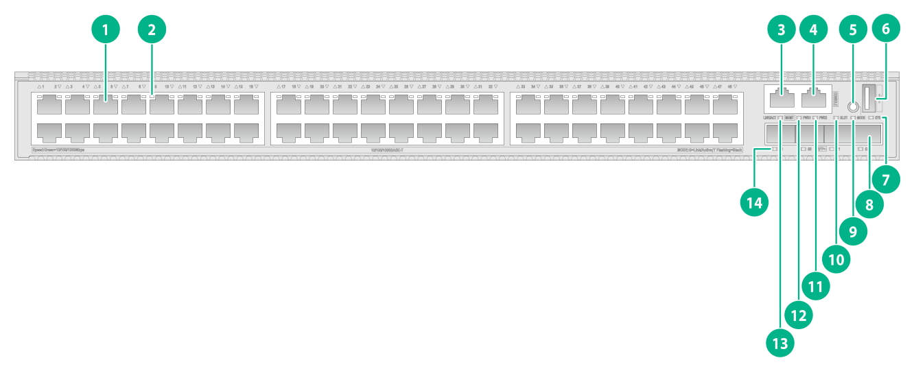
|
(1) 10/100/1000BASE-T autosensing Ethernet port |
(2) 10/100/1000BASE-T autosensing Ethernet port LED |
|
(3) Management Ethernet port (MGMT) |
(4) Console port (CONSOLE) |
|
(5) Mode button |
(6) USB port |
|
(7) System status LED (SYS) |
(8) SFP+ port |
|
(9) Mode LED (MODE) |
(10) Expansion card status LED (SLOT) |
|
(11) Power supply 2 status LED (PWR2) |
(12) Power supply 1 status LED (PWR1) |
|
(13) Management Ethernet port LED (ACT/LINK) |
(14) SFP+ port LED |

|
(1) Grounding screw |
(2) Expansion card |
|
(3) Fan tray 1 |
(4) Fan tray 2 |
|
(5) Power supply 1 |
(6) Power supply 2 |
The S5590-48T4XC-EI switch came with power supply slot 1 empty and power supply slot 2 installed with a filler panel. You can install one or two power supplies for the switch as required. In Figure2-12, two PSR180-12A-B AC power supplies are installed in the power supply slots.
The S5590-48T4XC-EI switch came with two fan tray slots empty. You must install two fan trays of the same model for the switch. In Figure2-12, two LSPM1FANSB-SN fan trays are installed in the fan tray slots.
The S5590-48T4XC-EI switch came with one expansion slot installed with a filler panel. You can select an expansion card for the switch as required. In Figure2-12, an LSWM2QP2P interface card is installed in the expansion slot.
S5590-28S8XC-EI
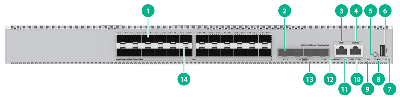
Figure2-13 Front panel
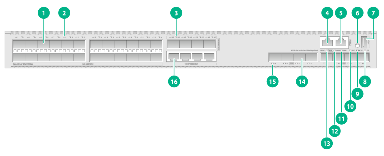
|
(1) SFP port |
(2) SFP port LED |
|
(3) 10/100/1000BASE-T autosensing Ethernet port LED |
(4) Management Ethernet port (MGMT) |
|
(5) Console port (CONSOLE) |
(6) Mode button |
|
(7) USB port |
(8) System status LED (SYS) |
|
(9) Mode LED (MODE) |
(10) Expansion card status LED (SLOT) |
|
(11) Power supply 2 status LED (PWR2) |
(12) Power supply 1 status LED (PWR1) |
|
(13) Management Ethernet port LED (ACT/LINK) |
(14) SFP+ port |
|
(15) SFP+ port LED |
(16) 10/100/1000BASE-T autosensing Ethernet port |

|
(1) Grounding screw |
(2) Expansion card |
|
(3) Fan tray 1 |
(4) Fan tray 2 |
|
(5) Power supply 1 |
(6) Power supply 2 |
The S5590-28S8XC-EI switch came with power supply slot 1 empty and power supply slot 2 installed with a filler panel. You can install one or two power supplies for the switch as required. In Figure2-14, two PSR180-12A-B AC power supplies are installed in the power supply slots.
The S5590-28S8XC-EI switch came with two fan tray slots empty. You must install two fan trays of the same model for the switch. In Figure2-14, two LSPM1FANSB-SN fan trays are installed in the fan tray slots.
The S5590-28S8XC-EI switch came with one expansion slot installed with a filler panel. You can select an expansion card for the switch as required. In Figure2-14, an LSWM2QP2P interface card is installed in the expansion slot.
The S5590-28S8XC-EI switch with PID LS-5590-28S8XC-EI-GL supports shipping with fan trays and power supplies installed. For the switch to be shipped with fan trays or power supplies installed, contact the marketing staff.
S5590-48S4XC-EI
Figure2-15 Front panel
|
(1) SFP port |
(2) SFP port LED |
|
(3) Management Ethernet port (MGMT) |
(4) Console port (CONSOLE) |
|
(5) Mode button |
(6) USB port |
|
(7) System status LED (SYS) |
(8) SFP+ port |
|
(9) Mode LED (MODE) |
(10) Expansion card status LED (SLOT) |
|
(11) Power supply 2 status LED (PWR2) |
(12) Power supply 1 status LED (PWR1) |
|
(13) Management Ethernet port LED (ACT/LINK) |
(14) SFP+ port LED |
|
(1) Grounding screw |
(2) Expansion card |
|
(3) Fan tray 1 |
(4) Fan tray 2 |
|
(5) Power supply 1 |
(6) Power supply 2 |
The S5590-48S4XC-EI switch came with power supply slot 1 empty and power supply slot 2 installed with a filler panel. You can install one or two power supplies for the switch as required. In Figure2-16, two PSR180-12A-B AC power supplies are installed in the power supply slots.
The S5590-48S4XC-EI switch came with two fan tray slots empty. You must install two fan trays of the same model for the switch. In Figure2-16, two LSPM1FANSB-SN fan trays are installed in the fan tray slots.
The S5590-48S4XC-EI switch came with one expansion slot installed with a filler panel. You can select an expansion card for the switch as required. In Figure2-16, an LSWM2QP2P interface card is installed in the expansion slot.
The S5590-48S4XC-EI switch with PID LS-5590-48S4XC-EI-GL supports shipping with fan trays and power supplies installed. For the switch to be shipped with fan trays or power supplies installed, contact the marketing staff.
S5590-28P8XC-EI
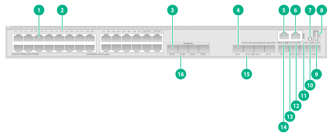
Figure2-17 Front panel
|
(1) 10/100/1000BASE-T autosensing Ethernet port |
(2) 10/100/1000BASE-T autosensing Ethernet port LED |
|
(3) SFP port |
(4) SFP+ port |
|
(5) Management Ethernet port (MGMT) |
(6) Console port (CONSOLE) |
|
(7) Mode button |
(8) USB port |
|
(9) System status LED (SYS) |
(10) Mode LED (MODE) |
|
(11) Expansion card status LED (SLOT) |
(12) Power supply 2 status LED (PWR2) |
|
(13) Power supply 1 status LED (PWR1) |
(14) Management Ethernet port LED (ACT/LINK) |
|
(15) SFP+ port LED |
(16) SFP port LED |
|
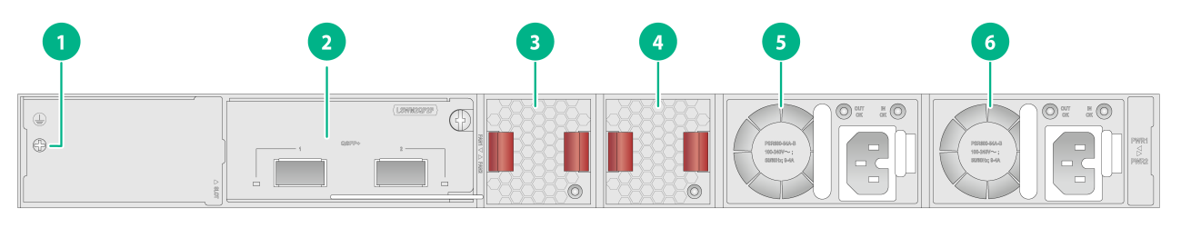
(1) Grounding screw |
(2) Expansion card |
|
(3) Fan tray 1 |
(4) Fan tray 2 |
|
(5) Power supply 1 |
(6) Power supply 2 |
The S5590-28P8XC-EI switch came with power supply slot 1 empty and power supply slot 2 installed with a filler panel. You can install one or two power supplies for the switch as required. In Figure2-18, two PSR600-54A-B AC power supplies are installed in the power supply slots.
The S5590-28P8XC-EI switch came with two fan tray slots empty. You must install two fan trays of the same model for the switch. In Figure2-18, two LSPM1FANSB-SN fan trays are installed in the fan tray slots.
The S5590-28P8XC-EI switch came with one expansion slot installed with a filler panel. You can select an expansion card for the switch as required. In Figure2-18, an LSWM2QP2P interface card is installed in the expansion slot.
The S5590-28P8XC-EI switch with PID LS-5590-28P8XC-EI-GL supports shipping with fan trays and power supplies installed. For the switch to be shipped with fan trays or power supplies installed, contact the marketing staff.
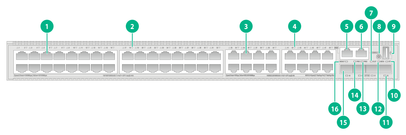
S5590-48P6XC-EI
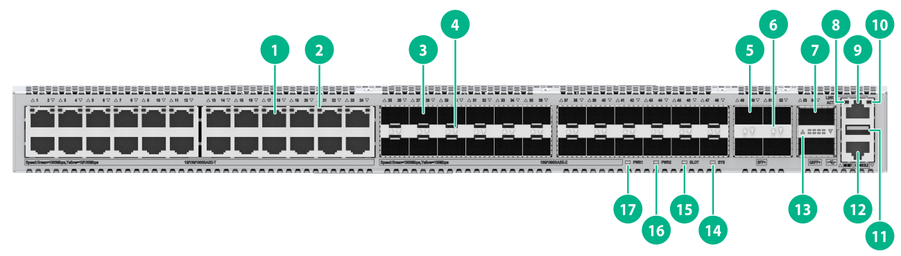
Figure2-19 Front panel
|
(1) 10/100/1000BASE-T autosensing Ethernet port |
(2) 10/100/1000BASE-T autosensing Ethernet port LED |
|
(3) SFP+ port |
(4) Console port (CONSOLE) |
|
(5) Mode LED (MODE) |
(6) System status LED (SYS) |
|
(7) Power supply 1 status LED (PWR1) |
(8) Power supply 2 status LED (PWR2) |
|
(9) Expansion card status LED (SLOT) |
(10) USB port |
|
(11) Mode button |
(12) Management Ethernet port LED (ACT/LINK) |
|
(13) Management Ethernet port (MGMT) |
(14) SFP+ port LED |

|
(1) Grounding screw |
(2) Expansion card |
|
(3) Fan tray 1 |
(4) Fan tray 2 |
|
(5) Power supply 1 |
(6) Power supply 2 |
The S5590-48P6XC-EI switch came with power supply slot 1 empty and power supply slot 2 installed with a filler panel. You can install one or two power supplies for the switch as required. In Figure2-20, two PSR600-54A-B AC power supplies are installed in the power supply slots.
The S5590-48P6XC-EI switch came with two fan tray slots empty. You must install two fan trays of the same model for the switch. In Figure2-20, two LSPM1FANSB-SN fan trays are installed in the fan tray slots.
The S5590-48P6XC-EI switch came with one expansion slot installed with a filler panel. You can select an expansion card for the switch as required. In Figure2-20, an LSWM2QP2P interface card is installed in the expansion slot.
The S5590-48P6XC-EI switch with PID LS-5590-48P6XC-EI-GL supports shipping with fan trays and power supplies installed. For the switch to be shipped with fan trays or power supplies installed, contact the marketing staff.
S5590-24X4YC-EI
Figure2-21 Front panel
|
(1) SFP+ port |
(2) SFP28 port |
|
(3) Management Ethernet port (MGMT) |
(4) Console port (CONSOLE) |
|
(5) Mode button |
(6) USB port |
|
(7) System status LED (SYS) |
(8) Mode LED (MODE) |
|
(9) Expansion card status LED (SLOT) |
(10) Power supply 2 status LED (PWR2) |
|
(11) Power supply 1 status LED (PWR1) |
(12) Management Ethernet port LED (LINK/ACT) |
|
(13) SFP28 port LED (SFP28) |
(14) SFP+ port LED |
|
(1) Grounding screw |
(2) Expansion card |
|
(3) Fan tray 1 |
(4) Fan tray 2 |
|
(5) Power supply 1 |
(6) Power supply 2 |
The S5590-24X4YC-EI switch came with power supply slot 1 empty and power supply slot 2 installed with a filler panel. You can install one or two power supplies for the switch as required. In Figure2-22, two PSR180-12A-B AC power supplies are installed in the power supply slots.
The S5590-24X4YC-EI switch came with two fan tray slots empty. You must install two fan trays of the same model for the switch. In Figure2-22, two LSPM1FANSB-SN fan trays are installed in the fan tray slots.
The S5590-24X4YC-EI switch came with one expansion slot installed with a filler panel. You can select an expansion card for the switch as required. In Figure2-22, an LSWM2SP8P interface card is installed in the expansion slot.
S5590-48TS4X2QC-EI
Figure2-23 Front panel
|
(1) 10/100/1000BASE-T autosensing Ethernet port |
(2) 10/100/1000BASE-T autosensing Ethernet port LED |
|
(3) SFP port |
(4) SFP port LED |
|
(5) SFP+ port |
(6) SFP+ port LED |
|
(7) QSFP+ port |
(8) Management Ethernet port LED (ACT) |
|
(9) Management Ethernet port (MGMT) |
(10) Management Ethernet port LED (LINK) |
|
(11) USB port |
(12) Console port (CONSOLE) |
|
(13) QSFP+ port LED |
(14) System status LED (SYS) |
|
(15) Expansion card status LED (SLOT) |
(16) Power supply 2 status LED (PWR2) |
|
(17) Power supply 1 status LED (PWR1) |
|

|
(1) Grounding screw |
(2) Expansion card |
|
(3) Fan tray 1 |
(4) Fan tray 2 |
|
(5) Power supply 1 |
(6) Power supply 2 |
The S5590-48TS4X2QC-EI switch came with power supply slot 1 empty and power supply slot 2 installed with a filler panel. You can install one or two power supplies for the switch as required. In Figure2-24, two PSR180-12A-B AC power supplies are installed in the power supply slots.
The S5590-48TS4X2QC-EI switch came with two fan tray slots empty. You must install two fan trays of the same model for the switch. In Figure2-24, two LSPM1FANSB-SN fan trays are installed in the fan tray slots.
The S5590-48TS4X2QC-EI switch came with one expansion slot installed with a filler panel. You can select an expansion card for the switch as required. In Figure2-24, an LSWM2SP8P interface card is installed in the expansion slot.
S5590-24UXM4YC-EI
Figure2-25 Front panel
|
(1) 10/100/1000BASE-T autosensing Ethernet port |
(2) 10/100/1000BASE-T autosensing Ethernet port LED |
|
(3) 10G/5G/2.5G/1000 BASE-T autosensing Ethernet port |
(4) 10G/5G/2.5G/1000 BASE-T autosensing Ethernet port LED |
|
(5) SFP28 port |
(6) Console port (CONSOLE) |
|
(7) Mode button |
(8) USB port |
|
(9) System status LED (SYS) |
(10) Mode LED (MODE) |
|
(11) Management Ethernet port LED (LINK/ACT) |
(12) Management Ethernet port |
|
(13) SFP28 port LED |
(14) Expansion card status LED (SLOT) |
|
(15) Power supply 2 status LED (PWR2) |
(16) Power supply 1 status LED (PWR1) |
|
(1) Grounding screw |
(2) Expansion card |
|
(3) Fan tray 1 |
(4) Fan tray 2 |
|
(5) Power supply 1 |
(6) Power supply 2 |
The S5590-24UXM4YC-EI switch came with power supply slot 1 empty and power supply slot 2 installed with a filler panel. You can install one or two power supplies for the switch as required. In Figure2-26, two PSR600-54A-B AC power supplies are installed in the power supply slots.
The S5590-24UXM4YC-EI switch came with two fan tray slots empty. You must install two fan trays of the same model for the switch. In Figure2-26, two LSPM1FANSB-SN fan trays are installed in the fan tray slots.
The S5590-24UXM4YC-EI switch came with one expansion slot installed with a filler panel. You can select an expansion card for the switch as required. In Figure2-26, an LSWM2SP2PB interface module is installed in the expansion slot.
S5590-48UXM4YC-EI
Figure2-27 Front panel
|
(1) 10/100/1000BASE-T autosensing Ethernet port |
(2) 10/100/1000BASE-T autosensing Ethernet port LED |
|
(3) 10G/5G/2.5G/1000 BASE-T autosensing Ethernet port |
(4) 10G/5G/2.5G/1000 BASE-T autosensing Ethernet port LED |
|
(5) Management Ethernet port |
(6) Console port (CONSOLE) |
|
(7) Expansion card status LED (SLOT) |
(8) Mode button |
|
(9) USB port |
(10) System status LED (SYS) |
|
(11) SFP28 port LED |
(12) Mode LED (MODE) |
|
(13) Power supply 2 status LED (PWR2) |
(14) Power supply 1 status LED (PWR1) |
|
(15) SFP28 port |
(16) Management Ethernet port LED (LINK/ACT) |

|
(1) Grounding screw |
(2) Expansion card |
|
(3) Fan tray 1 |
(4) Fan tray 2 |
|
(5) Power supply 1 |
(6) Power supply 2 |
The S5590-48UXM4YC-EI switch came with power supply slot 1 empty and power supply slot 2 installed with a filler panel. You can install one or two power supplies for the switch as required. In Figure2-28, two PSR600-54A-B AC power supplies are installed in the power supply slots.
The S5590-48UXM4YC-EI switch came with two fan tray slots empty. You must install two fan trays of the same model for the switch. In Figure2-28, two LSPM1FANSB-SN fan trays are installed in the fan tray slots.
The S5590-48UXM4YC-EI switch came with one expansion slot installed with a filler panel. You can select an expansion card for the switch as required. In Figure2-28, an LSWM2SP2PB interface module is installed in the expansion slot.
3 Removable components and compatibility matrixes
The switch supports removable components. Table3-1 and Table3-2 describes the removable components available for the switch.
Table3-1 Compatibility matrix between switches and removable components (1)
|
FRU model |
S5590-28T8XC-HI S5590-28S8XC-HI |
S5590-48T4XC-HI S5590-48S4XC-HI |
S5590-28T8XC-EI S5590-28S8XC-EI S5590-48T4XC-EI S5590-48S4XC-EI |
S5590-28P8XC-EI S5590-48P6XC-EI |
S5590-24UXM4YC-EI S5590-48UXM4YC-EI |
|
Removable power supplies |
|||||
|
PSR250-12A |
Supported |
Supported |
Not supported |
Not supported |
Not supported |
|
PSR250-12A1 |
Supported |
Supported |
Not supported |
Not supported |
Not supported |
|
PSR180-12A-B |
Not supported |
Not supported |
Supported |
Not supported |
Not supported |
|
PSR180-12A-F |
Not supported |
Not supported |
Supported |
Not supported |
Not supported |
|
PSR180-12D-B |
Not supported |
Not supported |
Supported |
Not supported |
Not supported |
|
PSR600-54A-B |
Not supported |
Not supported |
Not supported |
Supported |
Supported |
|
PSR920-54A-B |
Not supported |
Not supported |
Not supported |
Supported |
Supported |
|
PSR1600-54A-B |
Not supported |
Not supported |
Not supported |
Supported |
Supported |
|
Removable fan trays |
|||||
|
LSPM1FANSA-SN |
Supported |
Supported |
Supported |
Supported |
Not supported |
|
LSPM1FANSB-SN |
Supported |
Supported |
Supported |
Supported |
Supported |
|
Expansion cards |
|||||
|
LSPM6FWD |
Supported |
Expansion cards supported by expansion slots 1 and 2 depend on the port rate mode. For more information, see Table3-3. |
Supported |
Supported |
Not supported |
|
LSWM2EC |
Supported |
Supported |
Supported |
Supported |
|
|
LSWM2QP2P |
Supported |
Supported |
Supported |
Not supported |
|
|
LSWM2SP8P |
Supported |
Supported |
Supported |
Not supported |
|
|
LSWM2ZQP2P |
Supported |
Supported |
Supported |
Not supported |
|
|
LSWM2ZSP8P |
Supported |
Supported |
Supported |
Not supported |
|
|
LSWM2SP2PB |
Supported |
Supported |
Supported |
Supported |
|
|
LSWM2SP4PB |
Supported |
Supported |
Supported |
Supported |
|
|
LSWM2ZSP4P |
Not supported |
Not supported |
Not supported |
Not supported |
Supported |
|
LSWM2QP2PB |
Not supported |
Not supported |
Not supported |
Not supported |
Supported |
Table3-2 Compatibility matrix between switches and removable components (2)
|
FRU model |
S5590-24X4YC-EI |
S5590-48TS4X2QC-EI |
|
Removable power supplies |
||
|
PSR180-12A-B |
Supported |
Supported |
|
PSR180-12A-F |
Supported |
Supported |
|
PSR180-12D-B |
Supported |
Supported |
|
Removable fan trays |
||
|
LSPM1FANSA-SN |
Supported |
Supported |
|
LSPM1FANSB-SN |
Supported |
Supported |
|
Expansion cards |
||
|
LSPM6FWD |
Not supported |
Supported |
|
LSWM2QP2P |
Not supported |
Supported |
|
LSWM2SP8P |
Not supported |
Supported |
|
LSWM2ZQP2P |
Not supported |
Supported |
|
LSWM2ZSP8P |
Not supported |
Supported |
|
LSWM2SP2PB |
Supported |
Supported |
|
LSWM2SP4PB |
Supported |
Supported |
|
LSWM2EC |
Supported |
Supported |
|
LSWM2ZSP4P |
Supported |
Supported |
|
LSWM2QP2PB |
Supported |
Supported |
Table3-3 Expansion card and expansion slot compatibility for the S5590-48T4XC-HI and S5590-48S4XC-HI switches
|
Expansion card |
S5590-48T4XC-HI S5590-48S4XC-HI |
|
|||||
|
Expansion slot 1 |
Expansion slot 2 |
||||||
|
mode0 |
mode1 |
mode2 |
mode0 |
mode1 |
mode2 |
||
|
LSPM6FWD |
Supported |
Not supported |
Supported |
Supported |
Supported |
Supported |
|
|
LSWM2EC |
Not supported |
Supported |
Supported |
Supported |
Supported |
Supported |
|
|
LSWM2QP2P |
Supported |
Not supported |
Supported |
Supported |
Supported |
Supported |
|
|
LSWM2SP2PB |
Not supported |
Supported |
Supported |
Supported |
Supported |
Supported |
|
|
LSWM2SP4PB |
Not supported |
Supported |
Supported |
Supported |
Supported |
Supported |
|
|
LSWM2SP8P |
Not supported |
Not supported |
Supported |
Supported |
Supported |
Supported |
|
|
LSWM2ZQP2P |
Not supported |
Not supported |
Not supported |
Supported |
Supported |
Supported |
|
|
LSWM2ZSP8P |
Not supported |
Not supported |
Not supported |
Supported |
Supported |
Supported |
|
The power supplies support asset management. You can use the display device manuinfo command to view the name, sequence number, and vendor of the power supply you have installed on the switch.
For non-PoE switches, you can install one power supply, or two power supplies for 1+1 redundancy on the switch.
For PoE switches, you can install one power supply, or two power supplies for 1+1 redundancy on the switch. PoE capabilities vary by power supply configuration. When a power supply fails, PoE capabilities of the switch might decrease. For more information about PoE power capacity, see Table1-9.
The switch uses removable fan trays. Do not power on the switch if it does not have two fan trays of the same model installed.
For the S5590-48T4XC-HI and S5590-48S4XC-HI switches, you can use the port-speed-mode command to configure the port rate mode for an expansion slot. By default, the port rate mode for an expansion slot is mode0. To have the configuration take effect, you must save the configuration and restart the switch. For more information about the port-speed-mode command, see Ethernet interface commands in the command reference for the switch.
The S5590-28P8XC-EI (LS-5590-28P8XC-EI-GL), S5590-48P6XC-EI (LS-5590-48P6XC-EI-GL), S5590-28S8XC-EI (LS-5590-28S8XC-EI-GL), and S5590-48S4XC-EI (LS-5590-48S4XC-EI-GL) switches support shipping with fan trays and power supplies installed. For the switch to be shipped with fan trays or power supplies installed, contact the marketing staff.
4 Removable power supplies
250W power supplies (PSR250-12A and PSR250-12A1)
View
Figure4-1 PSR250-12A AC power supply view
The views of the PSR250-12A and PSR250-12A1 AC power supplies are similar, with only differences in the latch color and identifier.
For information about the status LED, see "Status LED on a PSR250-12A/PSR250-12A1 power supply."
Features
PSR250-12A and PSR250-12A1 are AC power supplies with AC or HVDC input and DC output. Table4-1 describes the features provided by the PSR250-12A and PSR250-12A1 power supplies.
Table4-1 Features provided by the PSR250-12A and PSR250-12A1 power supplies
|
Feature |
Description |
|
Protection function |
Protection against input overcurrent, input undervoltage, output overvoltage, output current limiting, output shortcircuit, and overtemperature conditions. |
|
Support for redundancy |
Two power supplies can be connected in parallel to achieve 1+1 redundancy and load balancing. |
|
Support for hot swapping |
You can remove one of the power supplies in 1+1 redundancy when the switch is operating correctly. |
Technical specifications
Table4-2 Technical specifications
|
Item |
Specification |
|
Dimensions (H × W × D) |
40.2 × 50.5 × 246 mm (1.58 × 1.99 × 9.69 in), including the handle |
|
Weight |
0.6 kg (1.32 lb) |
|
Rated AC input voltage range |
AC input: 100 VAC to 240 VAC @ 50 or 60 Hz HVDC input: 240 VDC |
|
Max AC input voltage range |
AC input: 90 VAC to 290 VAC @ 47 to 63 Hz HVDC input: 180 to 320 VDC |
|
Rated input current |
2 A to 4 A |
|
Rated output current |
2.5 A to 5 A |
|
Rated output voltage |
3.3 V to 12 V |
|
Rated output power |
250 W |
|
Melting current of power supply fuse |
15 A/250 V |
180W AC power supplies (PSR180-12A-F and PSR180-12A-B)
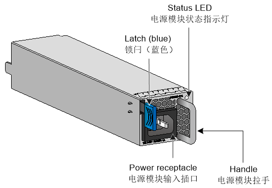
View
Figure4-2 PSR180-12A-B AC power supply view
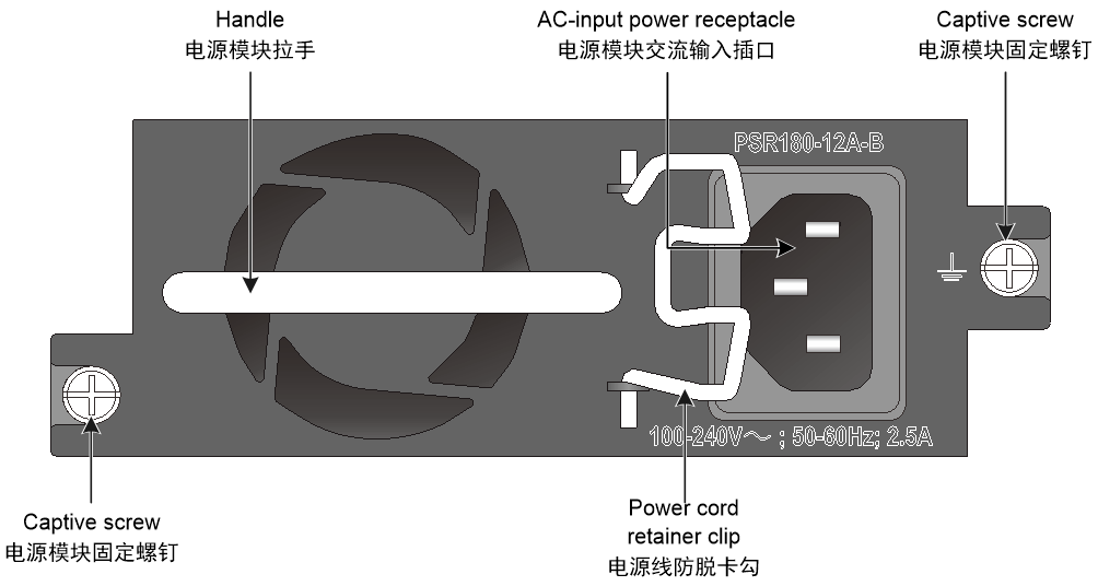
The views of the PSR180-12A-F and PSR180-12A-B AC power supplies are similar, with only differences in the identifier.
Features
PSR180-12A-F and PSR180-12A-B are AC power supplies with AC input and DC output. The power supplies provide an output voltage of 12 V and a maximum output of 180 W. Table4-3 describes the features provided by the PSR180-12A-F and PSR180-12A-B power supplies.
Table4-3 Features provided by the PSR180-12A-F and PSR180-12A-B power supplies
|
Feature |
Description |
|
Protection function |
Protection against input overcurrent, input undervoltage, output overvoltage, output current limiting, output shortcircuit, and overtemperature conditions. |
|
Support for redundancy |
Two power supplies can be connected in parallel to achieve 1+1 redundancy and load balancing. |
|
Support for hot swapping |
You can remove one of the power supplies in 1+1 redundancy when the switch is operating correctly. |
Technical specifications
Table4-4 Technical specifications
|
Item |
Specification |
|
Dimensions (H × W × D) |
41.1 × 101.6 × 207 mm (1.62 × 4.00 × 8.15 in), including the handle |
|
Weight |
0.8 kg (1.76 lb) |
|
Rated AC input voltage range |
100 VAC to 240 VAC @ 50 or 60 Hz |
|
Max AC input voltage range |
90 VAC to 264 VAC @ 47 to 63 Hz |
|
Rated input current |
N/A |
|
Rated output current |
15 A |
|
Rated output voltage |
12 V |
|
Rated output power |
180 W |
|
Melting current of power supply fuse |
6.3 A/250 V |
180W DC power supply (PSR180-12D-B)
View
Figure4-3 PSR180-12D-B DC power supply view

Features
PSR180-12D-B is a DC power supply with DC input and DC output. The power supply provides an output voltage of 12 V and a maximum output of 180 W. Table4-5 describes the features provided by the PSR180-12D-B power supply.
Table4-5 Features provided by the PSR180-12D-B power supply
|
Feature |
Description |
|
Protection function |
Protection against input overcurrent, input undervoltage, output overvoltage, output current limiting, output shortcircuit, and overtemperature conditions. |
|
Support for redundancy |
Two power supplies can be connected in parallel to achieve 1+1 redundancy and load balancing. |
|
Support for hot swapping |
You can remove one of the power supplies in 1+1 redundancy when the switch is operating correctly. |
Technical specifications
Table4-6 Technical specifications
|
Item |
Specification |
|
Dimensions (H × W × D) |
41.1 × 101.6 × 207 mm (1.62 × 4.00 × 8.15 in), including the handle |
|
Weight |
1 kg (2.20 lb) |
|
Rated input voltage range |
–48 to –60 VDC |
|
Max input voltage range |
–36 to –72 VDC |
|
Rated input current |
N/A |
|
Rated output current |
15 A |
|
Rated output voltage |
12 V |
|
Rated output power |
180 W |
|
Melting current of power supply fuse |
8 A/125 V |
600W power supply (PSR600-54A-B)
View
Figure4-4 PSR600-54A-B AC power supply view
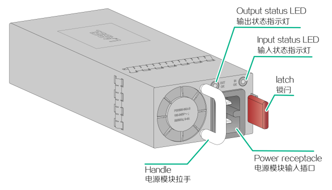
For information about the status LEDs, see "Status LEDs on a 600W/920W/1600W power supply."
Features
PSR600-54A-B is an AC power supply with AC or HVDC input and DC output. Table4-7 describes the features provided by the PSR600-54A-B power supply.
Table4-7 Features provided by the PSR600-54A-B power supply
|
Feature |
Description |
|
Protection function |
Protection against input overcurrent, input undervoltage, output overvoltage, output current limiting, output shortcircuit, and overtemperature conditions. |
|
Support for redundancy |
Two power supplies can be connected in parallel to achieve 1+1 redundancy and load balancing. |
|
Support for hot swapping |
You can remove one of the power supplies in 1+1 redundancy when the switch is operating correctly. |
Technical specifications
Table4-8 Technical specifications
|
Item |
Specification |
|
Dimensions (H × W × D) |
40.2 × 73.5 × 213.8 mm (1.58 × 2.89 × 8.42 in), including the handle |
|
Weight |
1 kg (2.20 lb) |
|
Rated AC input voltage range |
AC input: 100 VAC to 240 VAC @ 50 or 60 Hz HVDC input: 240 VDC |
|
Max AC input voltage range |
AC input: 90 VAC to 290 VAC @ 47 to 63 Hz HVDC input: 180 to 320 VDC |
|
Rated input current |
N/A |
|
Rated output current |
11 A |
|
Rated output voltage |
56 V |
|
Rated output power |
600 W |
|
Melting current of power supply fuse |
10 A/250 V |
920W power supply (PSR920-54A-B)
View
Figure4-5 PSR920-54A-B AC power supply view
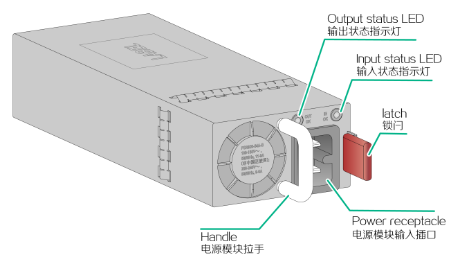
For information about the status LEDs, see "Status LEDs on a 600W/920W/1600W power supply."
Features
PSR920-54A-B is an AC power supply with AC or HVDC input and DC output. Table4-9 describes the features provided by the PSR920-54A-B power supply.
Table4-9 Features provided by the PSR920-54A-B power supply
|
Feature |
Description |
|
Protection function |
Protection against input overcurrent, input undervoltage, output overvoltage, output current limiting, output shortcircuit, and overtemperature conditions. |
|
Support for redundancy |
Two power supplies can be connected in parallel to achieve 1+1 redundancy and load balancing. |
|
Support for hot swapping |
You can remove one of the power supplies in 1+1 redundancy when the switch is operating correctly. |
Technical specifications
Table4-10 Technical specifications
|
Item |
Specification |
|
Dimensions (H × W × D) |
40.2 × 73.5 × 213.8 mm (1.58 × 2.89 × 8.42 in), including the handle |
|
Weight |
1 kg (2.20 lb) |
|
Rated AC input voltage range |
AC input: 100 VAC to 240 VAC @ 50 or 60 Hz HVDC input: 240 VDC |
|
Max AC input voltage range |
AC input: 90 VAC to 290 VAC @ 47 to 63 Hz HVDC input: 180 to 320 VDC |
|
Rated input current |
N/A |
|
Rated output current |
16.5 A |
|
Rated output voltage |
56 V |
|
Rated output power |
920 W |
|
Melting current of power supply fuse |
16 A/250 V |
1600W power supply (PSR1600-54A-B)
View
Figure4-6 PSR1600-54A-B AC power supply view

For information about the status LEDs, see "Status LEDs on a 600W/920W/1600W power supply."
Features
PSR1600-54A-B is an AC power supply with AC or HVDC input and DC output. Table4-11 describes the features provided by the PSR1600-54A-B power supply.
Table4-11 Features provided by the PSR1600-54A-B power supply
|
Feature |
Description |
|
Protection function |
Protection against input overcurrent, input undervoltage, output overvoltage, output current limiting, output shortcircuit, and overtemperature conditions. |
|
Support for redundancy |
Two power supplies can be connected in parallel to achieve 1+1 redundancy and load balancing. |
|
Support for hot swapping |
You can remove one of the power supplies in 1+1 redundancy when the switch is operating correctly. |
Technical specifications
Table4-12 Technical specifications
|
Item |
Specification |
|
Dimensions (H × W × D) |
40.2 × 73.5 × 213.8 mm (1.58 × 2.89 × 8.42 in), including the handle |
|
Weight |
1 kg (2.20 lb) |
|
Rated AC input voltage range |
AC input: 100 VAC to 240 VAC @ 50 or 60 Hz HVDC input: 240 VDC |
|
Max AC input voltage range |
AC input: 90 VAC to 290 VAC @ 47 to 63 Hz HVDC input: 180 to 320 VDC |
|
Rated input current |
N/A |
|
Rated output current |
· AC input: ¡ 17 A: 90 to 176 V @ 47 to 63 Hz ¡ 29 A: 176 to 290 V @ 47 to 63 Hz · HVDC input: 29 A |
|
Rated output voltage |
56 V |
|
Rated output power |
· AC input: ¡ 950 W: 90 to 176 V @ 47 to 63 Hz ¡ 1600 W: 176 to 290 V @ 47 to 63 Hz · HVDC input: 1600 W |
|
Melting current of power supply fuse |
16 A/125 V |
5 Removable fan trays
LSPM1FANSA-SN
View
Figure5-1 LSPM1FANSA-SN fan tray view
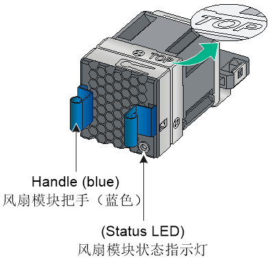
For information about the status LED, see "Fan tray status LED on a fan tray."
Features
The LSPM1FANSA-SN fan tray blows air from the power supply side to the port side. The fan tray features small size, fast heat dissipation, and hot swapping. It can automatically adjust the fan speed, providing powerful heat dissipation for the switch.
Technical specifications
Table5-1 Technical specifications
|
Item |
Specification |
|
Dimensions (H × W × D) |
40 × 40.6 × 105 mm (1.57 × 1.60 × 4.13 in), including the handle |
|
Fan quantity |
1 |
|
Weight |
N/A |
|
Airflow direction |
Air drawn in from the fan tray faceplate |
|
Fan speed |
20000 R.P.M |
|
Max airflow |
20 CFM (0.57 m3/min) |
|
Input voltage |
12 V |
|
Max power consumption |
9.8 W |
LSPM1FANSB-SN
View
Figure5-2 LSPM1FANSB-SN fan tray view
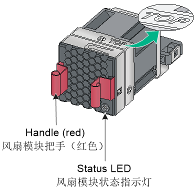
For information about the status LED, see "Fan tray status LED on a fan tray."
Features
The LSPM1FANSB-SN fan tray draws air from the port side to the power supply side. The fan tray features small size, fast heat dissipation, and hot swapping. It can automatically adjust the fan speed, providing powerful heat dissipation for the switch.
Technical specifications
Table5-2 Technical specifications
|
Item |
Specification |
|
Dimensions (H × W × D) |
40 × 40.6 × 105 mm (1.57 × 1.60 × 4.13 in), including the handle |
|
Fan quantity |
1 |
|
Weight |
N/A |
|
Airflow direction |
Air exhausted from the fan tray faceplate |
|
Fan speed |
20000 R.P.M |
|
Max airflow |
20 CFM (0.57 m3/min) |
|
Input voltage |
12 V |
|
Max power consumption |
9.8 W |
6 Expansion cards
LSWM2QP2P
About LSWM2QP2P
The LSWM2QP2P interface card provides two QSFP+ ports.
Figure6-1 LSWM2QP2P interface card view
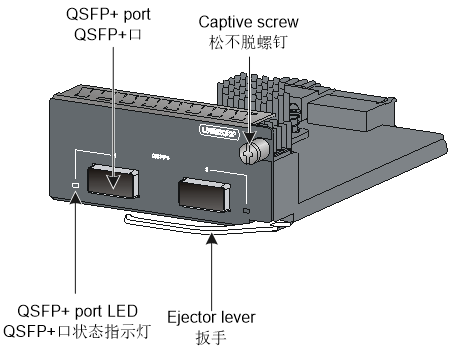
Ports and LEDs
For information about the ports and transceiver modules and cables available for the ports, see "QSFP+ port."
For information about the LEDs, see "QSFP+ port LED."
Technical specifications
Table6-1 Technical specifications
|
Item |
Specification |
|
Dimensions (H × W × D) |
40.1 × 95 × 147.5 mm (1.58 × 3.74 × 5.81 in) |
|
Weight |
0.4 kg (0.88 lb) |
|
Power consumption (static) |
9 W |
|
Power consumption (with typical configuration) |
10 W |
|
Power consumption (fully configured) |
14 W |
LSWM2SP8P/LSWM2SP8PM
About LSWM2SP8P and LSWM2SP8PM
The LSWM2SP8PM and LSWM2SP8P interface cards each provide eight SFP+ ports. The SFP+ ports on the LSWM2SP8PM interface card support MACsec. The views of LSWM2SP8P and LSWM2SP8PM are the same. This figure uses the LSWM2SP8P as an example.
Figure6-2 LSWM2SP8P interface card view
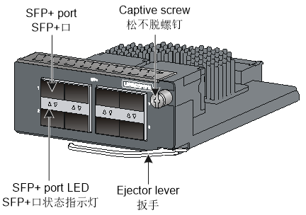
Ports and LEDs
For information about the ports and transceiver modules and cables available for the ports, see "SFP port" and "SFP+ port."
For information about the LEDs, see "LEDs on an LSWM2SP8P/LSWM2SP8PM interface card."
LSWM2ZQP2P
About LSWM2ZQP2P
The LSWM2ZQP2P interface module provides two QSFP28 ports.
Figure6-3 LSWM2ZQP2P interface module view

Ports and LEDs
For information about the ports and transceiver modules and cables available for the ports, see "QSFP+ port" and "QSFP28 ports."
For information about the LEDs, see "QSFP28 port LED."
LSWM2ZSP8P
About LSWM2ZSP8P
The LSWM2ZSP8P interface module provides eight SFP28 ports.
Figure6-4 LSWM2ZSP8P interface module view
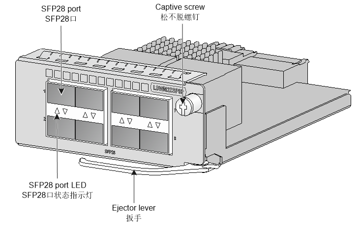
Ports and LEDs
For information about the ports and transceiver modules and cables available for the ports, see "SFP+ port" and "SFP28 port."
For information about the LEDs, see "SFP28 port LED."
|
|
NOTE: To use the LSWM2ZSP8P interface module, make sure the four lowest-numbered or four highest-numbered ports on the interface module have the same port rate and duplex mode. |
LSWM2EC
About LSWM2EC
The LSWM2EC EPS scanner module scans network-wide endpoints as instructed by the EPS server for port type and operating system type automatically and sends scanning results to the EPS server. Upon receiving the port information, the EPS server provides a baseline management over the endpoints that access the network system. By using this module on a switch, you can save hardware resources, increase the number of endpoints that can be scanned, and perform incremental scanning.
Figure6-5 LSWM2EC EPS scanner module view
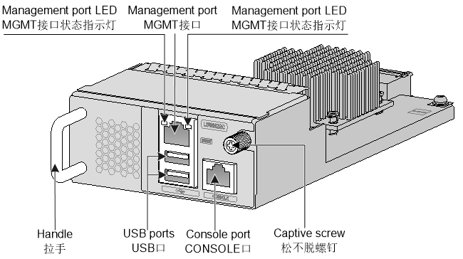
LEDs
For information about the management port LEDs, see "LEDs on an LSWM2EC EPS scanner module."
Technical specifications
Table6-2 Technical specifications
|
Item |
Specification |
|
Processor |
Intel C3758, 2.2 GHz |
|
DDR |
8G DDR4 |
|
Flash |
64GB EMMC |
|
Operating system |
Linux |
|
Maximum number of endpoints that can be scanned |
2500 |
|
Ports |
· 1 × management Ethernet port (MGMT) · 1 × console port · 2 × USB 3.0 ports |
|
Dimensions (H × W × D) |
41.1 × 95 × 197.5 mm (1.62 × 3.74 × 7.78 in) |
|
Weight |
0.5 kg (1.10 lb) |
|
Power consumption (static) |
14 W |
|
Power consumption (fully configured) |
30 W |
LSPM6FWD
About LSPM6FWD
The LSPM6FWD is a fourth-generation high performance firewall module. It provides features including firewall, VPN, content filtering, content identification, URL filtering, and NAT. By using this module on a switch, you can enhance the switch security capabilities without changing the network topology.
Figure6-6 LSPM6FWD front panel
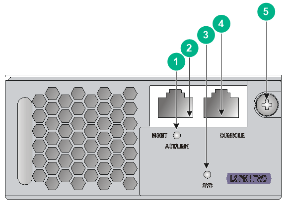
|
(1) Management Ethernet port LED (ACT/LINK) |
(2) 10/100/1000BASE-T management Ethernet port |
|
(3) System status LED (SYS) |
(4) Console port (CONSOLE) |
|
(5) Captive screw |
|
Ports and LEDs
For information about the ports and transceiver modules and cables available for the ports, see "Ports on an LSPM6FWD firewall module."
For information about the LEDs, see "LEDs on an LSPM6FWD firewall module."
Technical specifications
Table6-3 Technical specifications
|
Item |
Specification |
|
Dimensions (H × W × D) |
44.1 × 95 × 197.8 mm (1.74 × 3.74 × 7.79 in) |
|
Weight |
0.688 kg (1.52 lb) |
|
Power consumption (static) |
N/A |
|
Power consumption (with typical configuration) |
N/A |
|
Power consumption (fully configured) |
50 W |
LSWM2SP2PB
About LSWM2SP2PB
The LSWM2SP2PB interface module provides two SFP+ ports.
Figure6-7 LSWM2SP2PB interface module view
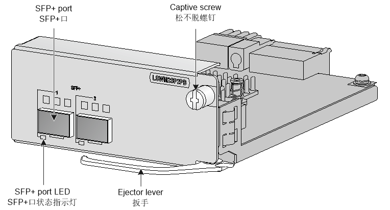
Ports and LEDs
For information about the ports and transceiver modules and cables available for the ports, see "SFP port" and "SFP+ port."
LSWM2SP4PB
About LSWM2SP4PB
The LSWM2SP4PB interface module provides four SFP+ ports.
Figure6-8 LSWM2SP4PB interface module view
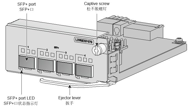
Ports and LEDs
For information about the ports and transceiver modules and cables available for the ports, see "SFP port" and "SFP+ port."
LSWM2ZSP4P
About LSWM2ZSP4P
The LSWM2ZSP4P interface module provides four SFP28 ports.
Figure6-9 LSWM2ZSP4P interface module view
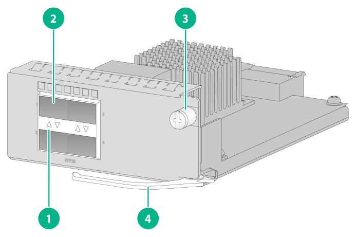
|
(1) SFP28 port LED |
(2) SFP28 port |
|
(3) Captive screw |
(4) Ejector lever |
Ports and LEDs
For information about the ports and transceiver modules and cables available for the ports, see "SFP+ port" and "SFP28 port."
For information about the LEDs, see "SFP28 port LED."
Technical specifications
Table6-4 Technical specifications
|
Item |
Specification |
|
Dimensions (H × W × D) |
40.1 × 95.0 × 147.5 mm (1.58 × 3.74 × 5.81 in) |
|
Weight |
0.4 kg (0.88 lb) |
|
Power consumption (static) |
5.0 W |
|
Power consumption (with typical configuration) |
6.0 W |
|
Power consumption (fully configured) |
11.0 W |
LSWM2QP2PB
About LSWM2QP2PB
The LSWM2QP2PB interface module provides two QSFP+ ports.
Figure6-10 LSWM2QP2PB interface module view
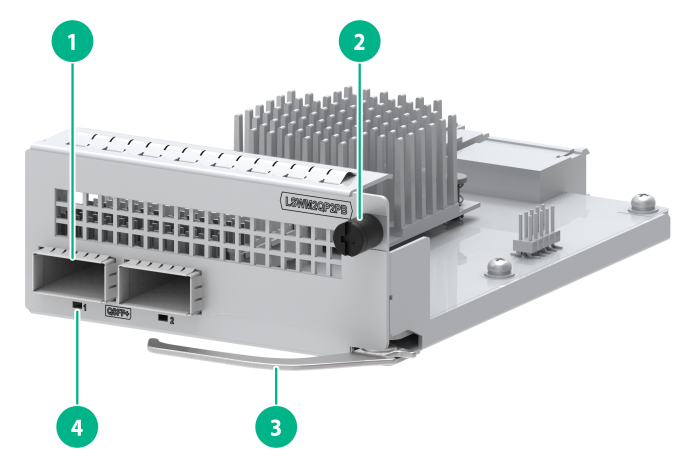
|
(1) QSFP+ port |
(2) Captive screw |
|
(3) Ejector lever |
(4) QSFP+ port LED |
Ports and LEDs
For information about the ports and transceiver modules and cables available for the ports, see "QSFP+ port."
Technical specifications
Table6-5 Technical specifications
|
Item |
Specification |
|
Dimensions (H × W × D) |
40.1 × 95 × 147.5 mm (1.58 × 3.74 × 5.81 in) |
|
Weight |
0.4 kg (0.88 lb) |
|
Power consumption (static) |
9 W |
|
Power consumption (with typical configuration) |
10 W |
|
Power consumption (fully configured) |
14 W |
7 Ports and LEDs
Ports
Console port
Table7-1 Console port specifications
|
Item |
Specification |
|
Connector type |
RJ-45 |
|
Compliant standard |
EIA/TIA-232 |
|
Port transmission rate |
9600 bps (default) to 115200 bps |
|
Services |
· Provides connection to an ASCII terminal · Provides connection to the serial port of a local PC running terminal emulation program |
|
Compatible devices |
All device models |
Management Ethernet port
Table7-2 Management Ethernet port specifications
|
Item |
Specification |
|
Connector type |
RJ-45 |
|
Port transmission rate |
· 10 Mbps, half/full duplex · 100 Mbps, half/full duplex · 1000 Mbps, full duplex · MDI/MDI-X autosensing |
|
Transmission medium |
Category-5 or above twisted pair cable |
|
Max transmission distance |
100 m (328.08 ft) |
|
Compliant standard |
IEEE 802.3i, 802.3u, and 802.3ab |
|
Functions and services |
Switch software and Boot ROM upgrade, network management |
|
Compatible devices |
All device models |
USB port
Table7-3 USB port specifications
|
Item |
Specification |
|
Port type |
USB 2.0 |
|
Compliant standard |
OHC |
|
Port transmission rate |
Uploads and downloads data at a rate up to 480 Mbps |
|
Functions and services |
Accesses the file system on the flash of the switch, for example, to upload or download application and configuration files |
|
Compatible devices |
All device models |
|
|
NOTE: USB devices from different vendors vary in compatibilities and drivers. H3C does not guarantee correct operation of USB devices from other vendors on the switch. If a USB device fails to operate on the switch, replace it with one from another vendor. |
SFP port
Table7-4 SFP port specifications
|
Item |
Specification |
|
Port type |
SFP port |
|
Compatible transceiver modules and cables |
· FE SFP transceiver modules in Table7-5 · GE SFP transceiver modules and cables in Table7-6 |
|
Compatible devices |
All device models (excluding the S5590-48T4XC-HI, S5590-48T4XC-EI, and S5590-48P6XC-EI switches) |
|
Restrictions and guidelines |
· When you use the SFP-GE-T or SFP-GE-T-D copper transceiver module, the interfaces can operate only at 1000 Mbps. · Only the S5590-28T8XC-EI (LS-5590-28T8XC-EI-GL and LS-5590-28T8XC-EI-H3) switch supports the SFP-FE-BX15-U-SM1310 transceiver module. · The S5590-28T8XC-EI (LS-5590-28T8XC-EI-GL and LS-5590-28T8XC-EI-H3) and S5590-48T4XC-EI (LS-5590-48T4XC-EI-GL and LS-5590-48T4XC-EI-H3) switches do not support the SFP-FE-LX-SM1310-D, SFP-FE-LX-SM1310-BIDI, and SFP-GE-SX-MM850-D transceiver modules. · The S5590-24X4YC-EI (LS-S5590-24X4YC-EI), S5590-24UXM4YC-EI, and S5590-48UXM4YC-EI switches do not support FE SFP transceiver modules. · The S5590-48TS4X2QC-EI (LS-S5590-48TS4X2QC-EI) switch does not support the SFP-FE-LX-SM1310-D and SFP-GE-SX-MM850-D transceiver modules. |
Table7-5 FE SFP transceiver modules available for the SFP ports
|
FE SFP transceiver module |
Central wavelength (nm) |
Connector |
Fiber diameter (µm) |
Max transmission distance |
|
SFP-FE-SX-MM1310-A |
1310 |
LC |
Multi-mode, 50/125 |
2 km (1.24 miles) |
|
Multi-mode, 62.5/125 |
||||
|
SFP-FE-LX-SM1310-A |
1310 |
LC |
Single-mode, 9/125 |
15 km (9.32 miles) |
|
SFP-FE-LX-SM1310-D |
1310 |
LC |
Single-mode, 9/125 |
15 km (9.32 miles) |
|
SFP-FE-BX15-U-SM1310 |
1310 |
LC |
Single-mode, 9/125 |
15 km (9.32 miles) |
|
SFP-FE-LH40-SM1310 |
1310 |
LC |
Single-mode, 9/125 |
40 km (24.86 miles) |
|
SFP-FE-LH80-SM1550 |
1550 |
LC |
Single-mode, 9/125 |
80 km (49.71 miles) |
|
SFP-FE-LX-SM1310-BIDI |
TX: 1310 RX: 1550 |
LC |
Single-mode, 9/125 |
15 km (9.32 miles) |
|
SFP-FE-LX-SM1550-BIDI |
TX: 1550 RX: 1310 |
LC |
Single-mode, 9/125 |
15 km (9.32 miles) |
|
|
IMPORTANT: The SFP-FE-LX-SM1310-BIDI and SFP-FE-LX-SM1550-BIDI transceiver modules must be used in pairs. For example, if one end uses the SFP-FE-LX-SM1310-BIDI transceiver module, the other end must use the SFP-FE-LX-SM1550-BIDI transceiver module. |
Table7-6 GE SFP transceiver modules and cables available for the SFP+ ports
|
GE SFP transceiver module and cable |
Central wavelength (nm) |
Connector |
Cable/Fiber type and diameter (µm) |
Modal bandwidth (MHz × km) |
Max transmission distance |
|
SFP copper transceiver modules |
|||||
|
SFP-GE-T |
N/A |
RJ-45 |
Twisted pair cable |
N/A |
100 m (328.08 ft) |
|
SFP-GE-T-D |
N/A |
RJ-45 |
Twisted pair cable |
N/A |
100 m (328.08 ft) |
|
SFP fiber transceiver modules |
|||||
|
SFP-GE-SX-MM850-A |
850 |
LC |
Multi-mode, 50/125 |
500 |
550 m (1804.46 ft) |
|
400 |
500 m (1640.42 ft) |
||||
|
Multi-mode, 62.5/125 |
200 |
275 m (902.23 ft) |
|||
|
160 |
220 m (721.78 ft) |
||||
|
SFP-GE-SX-MM850-D |
850 |
LC |
Multi-mode, 50/125 |
500 |
550 m (1804.46 ft) |
|
400 |
500 m (1640.42 ft) |
||||
|
Multi-mode, 62.5/125 |
200 |
275 m (902.23 ft) |
|||
|
160 |
220 m (721.78 ft) |
||||
|
SFP-GE-LX-SM1310-A |
1310 |
LC |
Single-mode, 9/125 |
N/A |
10 km (6.21 miles) |
|
Multi-mode, 50/125 |
500 or 400 |
550 m (1804.46 ft) |
|||
|
Multi-mode, 62.5/125 |
500 |
550 m (1804.46 ft) |
|||
|
SFP-GE-LX10-SM1310 |
1310 |
LC |
Single-mode, 9/125 |
N/A |
10 km (6.21 miles) |
|
SFP-GE-LH20-SM1310-I |
1310 |
LC |
Single-mode, 9/125 |
N/A |
20 km (12.43 miles) |
|
SFP-GE-LH40-SM1310-I |
1310 |
LC |
Single-mode, 9/125 |
N/A |
40 km (24.86 miles) |
|
SFP-GE-LH40-SM1310 |
1310 |
LC |
Single-mode, 9/125 |
N/A |
40 km (24.86 miles) |
|
SFP-GE-LH40-SM1310-D |
1310 |
LC |
Single-mode, 9/125 |
N/A |
40 km (24.86 miles) |
|
SFP-GE-LH40-SM1550 |
1550 |
LC |
Single-mode, 9/125 |
N/A |
40 km (24.86 miles) |
|
SFP-GE-LH80-SM1550 |
1550 |
LC |
Single-mode, 9/125 |
N/A |
80 km (49.71 miles) |
|
SFP-GE-LH80-SM1550-D |
1550 |
LC |
Single-mode, 9/125 |
N/A |
80 km (49.71 miles) |
|
SFP-GE-LH100-SM1550 |
1550 |
LC |
Single-mode, 9/125 |
N/A |
100 km (62.14 miles) |
|
SFP-GE-LX-SM1310-BIDI |
TX: 1310 RX: 1490 |
LC |
Single-mode, 9/125 |
N/A |
10 km (6.21 miles) |
|
SFP-GE-LX-SM1490-BIDI |
TX: 1490 RX: 1310 |
LC |
Single-mode, 9/125 |
N/A |
10 km (6.21 miles) |
|
SFP-GE-LH70-SM1490-BIDI |
TX: 1490 RX: 1550 |
LC |
Single-mode, 9/125 |
N/A |
70 km (43.50 miles) |
|
SFP-GE-LH70-SM1550-BIDI |
TX: 1550 RX: 1490 |
LC |
Single-mode, 9/125 |
N/A |
70 km (43.50 miles) |
|
SFP-GE-LH40-SM1310-BIDI |
TX: 1310 RX: 1550 |
LC |
Single-mode, 9/125 |
N/A |
40 km (24.86 miles) |
|
SFP-GE-LH40-SM1550-BIDI |
TX: 1550 RX: 1310 |
LC |
Single-mode, 9/125 |
N/A |
40 km (24.86 miles) |
|
SFP cable |
|||||
|
SFP-STACK-Kit |
N/A |
N/A |
N/A |
SFP cable |
1.5 m (4.92 ft) |
|
|
IMPORTANT: The SFP-GE-LX-SM1310-BIDI and SFP-GE-LX-SM1490-BIDI transceiver modules, SFP-GE-LH70-SM1550-BIDI and SFP-GE-LH70-SM1490-BIDI transceiver modules, and SFP-GE-LH40-SM1310-BIDI and SFP-GE-LH40-SM1550-BIDI transceiver modules must be used in pairs. For example, if one end uses the SFP-GE-LX-SM1310-BIDI transceiver module, the other end must use the SFP-GE-LX-SM1490-BIDI transceiver module. |
|
|
NOTE: · As a best practice, use H3C transceiver modules and network cables for the switch. · The H3C transceiver modules and network cables are subject to change over time. For the most recent list of H3C transceiver modules and cables, contact H3C Support or marketing staff. · For the specifications of H3C transceiver modules and network cables, see H3C Transceiver Modules User Guide. |
SFP+ port
Table7-7 SFP+ port specifications
|
Item |
Specification |
|
Port type |
SFP+ port |
|
Compatible transceiver modules and cables |
· GE SFP transceiver modules and cables in Table7-6 · 10GE SFP+ transceiver modules and cables in Table7-8, Table7-9, and Table7-10 |
|
Compatible devices |
All device models and the LSWM2SP8P, LSWM2SP2PB, and LSWM2SP4PB expansion cards |
|
Restrictions and guidelines |
· The S5590-28T8XC-EI (LS-5590-28T8XC-EI-GL and LS-5590-28T8XC-EI-H3) and S5590-48T4XC-EI (LS-5590-48T4XC-EI-GL and LS-5590-48T4XC-EI-H3) switches do not support the SFP-XG-SX-MM850-A and SFP-XG-LX-SM1310-E transceiver modules. · The S5590-24X4YC-EI, S5590-48TS4X2QC-EI, S5590-24UXM4YC-EI, and S5590-48UXM4YC-EI switches do not support the SFP-XG-SX-MM850-A, SFP-XG-LX-SM1310-E, and SFP-XG-LH80-Tunable transceiver modules. |
Table7-8 10GE SFP+ transceiver modules available for the SFP+ ports
|
10GE SFP+ transceiver module |
Central wavelength (nm) |
Connector |
Fiber diameter (µm) |
Modal bandwidth (MHz × km) |
Max transmission distance |
|
SFP-XG-SX-MM850-A |
850 |
LC |
Multi-mode, 50/125 |
2000 |
300 m (984.25 ft) |
|
500 |
82 m (269.03 ft) |
||||
|
400 |
66 m (216.54 ft) |
||||
|
Multi-mode, 62.5/125 |
200 |
33 m (108.27 ft) |
|||
|
160 |
26 m (85.30 ft) |
||||
|
SFP-XG-SX-MM850-D |
850 |
LC |
Multi-mode, 50/125 |
2000 |
300 m (984.25 ft) |
|
500 |
82 m (269.03 ft) |
||||
|
400 |
66 m (216.54 ft) |
||||
|
Multi-mode, 62.5/125 |
200 |
33 m (108.27 ft) |
|||
|
160 |
26 m (85.30 ft) |
||||
|
SFP-XG-LX-SM1310 |
1310 |
LC |
Single-mode, 9/125 |
N/A |
10 km (6.21 miles) |
|
SFP-XG-LX-SM1310-D |
1310 |
LC |
Single-mode, 9/125 |
N/A |
10 km (6.21 miles) |
|
SFP-XG-LX-SM1310-E |
1310 |
LC |
Single-mode, 9/125 |
N/A |
10 km (6.21 miles) |
|
SFP-XG-LH40-SM1550 |
1550 |
LC |
Single-mode, 9/125 |
N/A |
40 km (24.86 miles) |
|
SFP-XG-LH40-SM1550-D |
1550 |
LC |
Single-mode, 9/125 |
N/A |
40 km (24.86 miles) |
|
SFP-XG-LH80-SM1550 |
1550 |
LC |
Single-mode, 9/125 |
N/A |
80 km (49.71 miles) |
|
SFP-XG-LH80-SM1550-D |
1550 |
LC |
Single-mode, 9/125 |
N/A |
80 km (49.71 miles) |
|
SFP-XG-CPRI-IR-SM1310 |
1310 |
LC |
Single-mode, 9/125 |
N/A |
1.4 km (0.87 miles) |
|
SFP-XG-CPRI-LR-SM1310 |
1310 |
LC |
Single-mode, 9/125 |
N/A |
10 km (6.21 miles) |
|
SFP-XG-LH80-Tunable |
1547.75 |
LC |
Single-mode, 9/125 |
N/A |
80 km (49.71 miles) |
|
SFP-XG-LX-SM1270-BIDI |
TX: 1270 RX: 1330 |
LC |
Single-mode, 9/125 |
N/A |
10 km (6.21 miles) |
|
SFP-XG-LX-SM1330-BIDI |
TX: 1330 RX: 1270 |
LC |
Single-mode, 9/125 |
N/A |
10 km (6.21 miles) |
|
SFP-XG-LH40-SM1270-BIDI |
TX: 1270 RX: 1330 |
LC |
Single-mode, 9/125 |
N/A |
40 km (24.86 miles) |
|
SFP-XG-LH40-SM1330-BIDI |
TX: 1330 RX: 1270 |
LC |
Single-mode, 9/125 |
N/A |
40 km (24.86 miles) |
|
SFP-XG-LH80-SM1490-BIDI |
TX: 1490 RX: 1550 |
LC |
Single-mode, 9/125 |
N/A |
80 km (49.71 miles) |
|
SFP-XG-LH80-SM1550-BIDI |
TX: 1550 RX: 1490 |
LC |
Single-mode, 9/125 |
N/A |
80 km (49.71 miles) |
|
|
IMPORTANT: The SFP-XG-LX-SM1270-BIDI and SFP-XG-LX-SM1330-BIDI transceiver modules, SFP-XG-LH40-SM1270-BIDI and SFP-XG-LH40-SM1330-BIDI transceiver modules, and SFP-XG-LH80-SM1490-BIDI and SFP-XG-LH80-SM1550-BIDI transceiver modules must be used in pairs. For example, if one end uses an SFP-XG-LX-SM1270-BIDI transceiver module, the other end must use an SFP-XG-LX-SM1330-BIDI transceiver module. |
Table7-9 SFP+ copper cables available for the SFP+ ports
|
SFP+ copper cable |
Cable length |
|
LSWM1STK |
0.65 m (2.13 ft) |
|
LSWM2STK |
1.2 m (3.94 ft) |
|
LSWM3STK |
3 m (9.84 ft) |
|
LSTM1STK |
5 m (16.40 ft) |
Table7-10 SFP+ fiber cables available for the SFP+ ports
|
SFP+ fiber cable |
Cable length |
|
SFP-XG-D-AOC-7M |
7 m (22.97 ft) |
|
SFP-XG-D-AOC-10M |
10 m (32.81 ft) |
|
SFP-XG-D-AOC-20M |
20 m (65.62 ft) |
Figure7-1 SFP+ cable
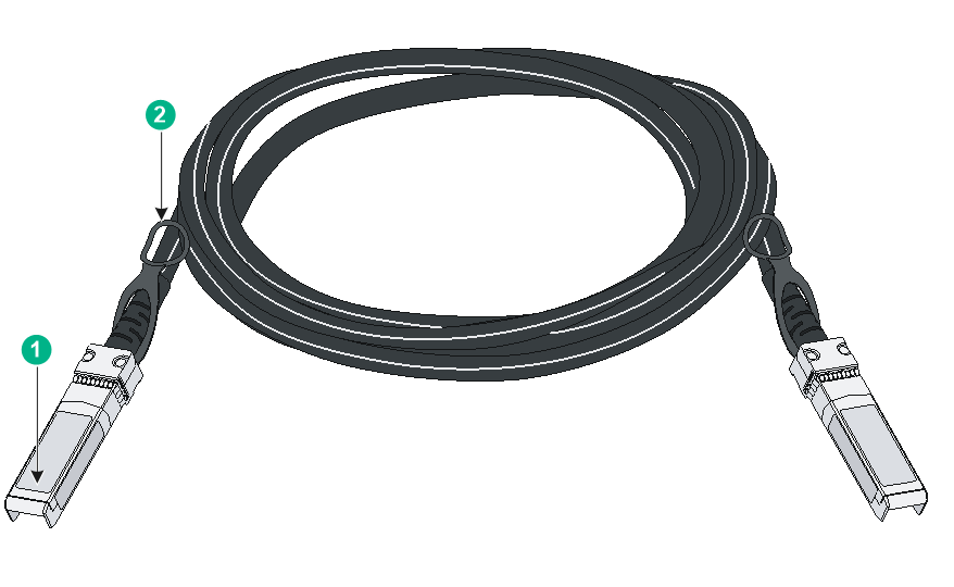
|
(1) Connector |
(2) Pull latch |
|
|
NOTE: · As a best practice, use H3C transceiver modules and network cables for the switch. · The H3C transceiver modules and network cables are subject to change over time. For the most recent list of H3C transceiver modules and cables, contact H3C Support or marketing staff. · For the specifications of H3C transceiver modules and network cables, see H3C Transceiver Modules User Guide. |
SFP28 port
The LSWM2ZSP8P interface module and the S5590-24X4YC-EI, S5590-24UXM4YC-EI, and S5590-48UXM4YC-EI switches provide SFP28 ports. To connect peer SFP28/SFP+ ports over a long distance, use SFP28/SFP+ transceiver modules and fibers. To connect peer SFP28/SFP+ ports over a short distance, use SFP28/SFP+ cables.
SFP28 ports support the following transceiver modules and cables:
· SFP28 transceiver modules in Table7-11.
· SFP28 cables in Table7-12.
· SFP+ transceiver modules in Table7-8.
· SFP+ copper cables in Table7-9.
· SFP+ fiber cables in Table7-10.
Table7-11 SFP28 transceiver modules available for the SFP28 ports
|
SFP28 transceiver module |
Central wavelength (nm) |
Connector |
Cable/Fiber type and diameter (µm) |
Modal bandwidth (MHz × km) |
Max transmission distance |
|
SFP-25G-SR-MM850 |
850 |
LC |
Multi-mode, 50/125 |
2000 |
70 m (229.66 ft) |
|
4700 |
100 m (328.08 ft) |
||||
|
SFP-25G-SR-MM850-H |
850 |
LC |
Multi-mode, 50/125 |
2000 |
70 m (229.66 ft) |
|
4700 |
100 m (328.08 ft) |
||||
|
SFP-25G-CSR-MM850 |
850 |
LC |
Multi-mode, 50/125 |
2000 |
200 m (656.17 ft) |
|
>3500 |
300 m (984.25 ft) |
||||
|
>5500 |
400 m (1312.34 ft) |
||||
|
SFP-25G-LR-SM1310 |
1310 |
LC |
Single-mode, 9/125 |
N/A |
10 km (6.21 miles) |
|
SFP-25G-LR-SM1310-I |
1310 |
LC |
Single-mode, 9/125 |
N/A |
10 km (6.21 miles) |
Table7-12 SFP28 cables available for the SFP28 ports
|
SFP28 cable |
Cable length |
|
SFP-25G-D-CAB-1M |
1 m (3.28 ft) |
|
SFP-25G-D-CAB-3M |
3 m (9.84 ft) |
|
SFP-25G-D-CAB-5M |
5 m (16.40 ft) |
|
SFP-25G-D-AOC-3M |
3 m (9.84 ft) |
|
SFP-25G-D-CAB-4M-A |
4 m (13.12 ft) |
|
SFP-25G-D-AOC-5M |
5 m (16.40 ft) |
|
SFP-25G-D-AOC-7M |
7 m (22.97 ft) |
|
SFP-25G-D-AOC-10M |
10 m (32.81 ft) |
|
SFP-25G-D-AOC-20M |
20 m (65.62 ft) |

|
(1) Connector |
(2) Pull latch |
|
|
IMPORTANT: The SFP-25G-D-CAB-4M-A cable is not supported by the S5590-24X4YC-EI, S5590-48TS4X2QC-EI, S5590-24UXM4YC-EI, or S5590-48UXM4YC-EI switch. |
|
|
NOTE: · As a best practice, use H3C transceiver modules and cables for the switch. · The H3C transceiver modules and cables are subject to change over time. For the most recent list of H3C transceiver modules and cables, contact your H3C Support or marketing staff. · For more information about H3C transceiver modules and cables, see H3C Transceiver Modules User Guide. |
QSFP+ port
Each LSWM2QP2P interface card or S5590-48TS4X2QC-EI switch provides two QSFP+ ports. You can install the QSFP+ transceiver modules in Table7-13, QSFP+ copper cables in Table7-14, and QSFP+ fiber cables in Table7-15.
Table7-13 QSFP+ transceiver modules available for the QSFP+ ports
|
QSFP+ transceiver module |
Central wavelength (nm) |
Connector |
Fiber type and diameter (µm) |
Modal bandwidth (MHz × km) |
Max transmission distance |
|
QSFP-40G-SR4-MM850 |
850 |
MPO |
Multi-mode, 50/125 |
2000 |
100 m (328.08 ft) |
|
4700 |
150 m (492.13 ft) |
||||
|
QSFP-40G-CSR4-MM850 |
850 |
MPO |
Multi-mode, 50/125 |
2000 |
300 m (984.25 ft) |
|
4700 |
400 m (1312.34 ft) |
||||
|
QSFP-40G-BIDI-SR-MM850 |
Two lanes: · 850 · 900 |
LC |
Multi-mode, 50/125 |
2000 |
100 m (328.08 ft) |
|
4700 |
150 m (492.13 ft) |
||||
|
QSFP-40G-BIDI-WDM850 |
Four lanes: · 850 · 880 · 910 · 940 |
LC |
Multi-mode, 50/125 |
2000 |
240 m (787.40 ft) |
|
4700 |
350 m (1148.29 ft) |
||||
|
QSFP-40G-LR4-PSM1310 |
1310 |
MPO |
Multi-mode, 50/125 |
N/A |
10 km (6.21 miles) |
|
QSFP-40G-LR4-WDM1300 |
Four lanes: · 1271 · 1291 · 1311 · 1331 |
LC |
Single-mode, 9/125 |
N/A |
10 km (6.21 miles) |
|
QSFP-40G-LR4L-WDM1300 |
Four lanes: · 1271 · 1291 · 1311 · 1331 |
LC |
Single-mode, 9/125 |
N/A |
2 km (1.24 miles) |
|
QSFP-40G-ER4-WDM1300 |
Four lanes: · 1271 · 1291 · 1311 · 1331 |
LC |
Single-mode, 9/125 |
N/A |
40 km (24.86 miles) |
|
|
IMPORTANT: · The QSFP-40G-SR4-MM850 transceiver module is not supported by the S5590-28T8XC-EI (LS-5590-28T8XC-EI-GL and LS-5590-28T8XC-EI-H3) or S5590-48T4XC-EI (LS-5590-48T4XC-EI-GL and LS-5590-48T4XC-EI-H3) switch with LSWM2QP2P interface cards installed. · The QSFP-40G-CSR4-MM850 transceiver module is not supported by the S5590-24X4YC-EI and S5590-48TS4X2QC-EI switches. |
Table7-14 40G QSFP+ copper cables available for the QSFP+ ports
|
QSFP+ copper cable |
Max transmission distance |
|
LSWM1QSTK0 |
1 m (3.28 ft) |
|
LSWM1QSTK1 |
3 m (9.84 ft) |
|
LSWM1QSTK2 |
5 m (16.40 ft) |
Table7-15 40G QSFP+ fiber cables available for the QSFP+ ports
|
QSFP+ fiber cable |
Max transmission distance |
|
QSFP-40G-D-AOC-3M |
3 m (9.84 ft) |
|
QSFP-40G-D-AOC-7M |
7 m (22.97 ft) |
|
QSFP-40G-D-AOC-10M |
10 m (32.81 ft) |
|
QSFP-40G-D-AOC-20M |
20 m (65.62 ft) |
Figure7-3 40G QSFP+ cable

|
(1) Connector |
(2) Pull tab |
|
|
NOTE: · As a best practice, use H3C transceiver modules and cables for the switch. · The H3C transceiver modules and cables are subject to change over time. For the most recent list of H3C transceiver modules and cables, contact your H3C Support or marketing staff. · For more information about H3C transceiver modules and cables, see H3C Transceiver Modules User Guide. |
QSFP28 ports
The LSWM2ZQP2P interface module provides two QSFP28 ports.
QSFP28 ports support the following transceiver modules and cables:
· QSFP28 transceiver modules in Table7-16.
· QSFP28 fiber cables in Table7-17.
· QSFP28 fiber cables in Table7-18.
· QSFP+ transceiver modules in Table7-13.
· QSFP+ copper cables in Table7-14.
· QSFP+ fiber cables in Table7-15.
Table7-16 QSFP28 transceiver modules available for the QSFP28 ports
|
QSFP28 transceiver module |
Central wavelength (nm) |
Connector |
Fiber type and diameter (µm) |
Modal bandwidth (MHz*km) |
Maximum transmission distance |
|
QSFP-100G-SR4-MM850 |
850 |
MPO |
Multi-mode, 50/125 |
2000 |
70 m (229.66 ft) |
|
4700 |
100 m (328.08 ft) |
||||
|
QSFP-100G-SR4-MM850-H |
850 |
MPO |
Multi-mode, 50/125 |
2000 |
70 m (229.66 ft) |
|
4700 |
100 m (328.08 ft) |
||||
|
QSFP-100G-SWDM4-MM850 |
Four lanes: · 850 · 880 · 910 · 940 |
LC |
Multi-mode, 50/125 |
2000 |
70 m (229.66 ft) |
|
4700 |
100 m (328.08 ft) |
||||
|
QSFP-100G-eSR4-MM850 |
850 |
MPO |
Multi-mode, 50/125 |
4700 |
300 m (984.25 ft) |
|
QSFP-100G-PSM4-SM1310 |
1310 |
MPO |
Single-mode, 9/125 |
N/A |
0.5 km (0.31 miles) |
|
QSFP-100G-LR4-WDM1300 |
Four lanes: · 1295.56 · 1300.05 · 1304.58 · 1309.14 |
LC |
Single-mode, 9/125 |
N/A |
10 km (6.21 miles) |
|
QSFP-100G-LR4L-WDM1300 |
Four lanes: · 1271 · 1291 · 1311 · 1331 |
LC |
Single-mode, 9/125 |
N/A |
2 km (1.24 miles) |
|
QSFP-100G-ER4-WDM1300 |
Four lanes: · 1295.56 · 1300.05 · 1304.58 · 1309.14 |
LC |
Single-mode, 9/125 |
N/A |
40 km (24.86 miles) |
|
QSFP-100G-ZR4-WDM1300 |
Four lanes: · 1295.56 · 1300.05 · 1304.58 · 1309.14 |
LC |
Single-mode, 9/125 |
N/A |
80 km (49.71 miles) |
|
QSFP-100G-ER4L-WDM1300 |
Four lanes: · 1295 · 1300 · 1304 · 1309 |
LC |
Single-mode, 9/125 |
N/A |
40 km (24.86 miles) |
Table7-17 100G QSFP28 fiber cables available for the QSFP28 ports
|
QSFP28 fiber cable |
Cable length |
|
QSFP-100G-D-AOC-7M |
7 m (22.97 ft) |
|
QSFP-100G-D-AOC-7M-H |
7 m (22.97 ft) |
|
QSFP-100G-D-AOC-10M |
10 m (32.81 ft) |
|
QSFP-100G-D-AOC-10M-H |
10 m (32.81 ft) |
|
QSFP-100G-D-AOC-20M |
20 m (65.62 ft) |
|
QSFP-100G-D-AOC-20M-H |
20 m (65.62 ft) |
Table7-18 100G QSFP28 copper cables available for the QSFP28 ports
|
QSFP28 copper cable |
Cable length |
|
QSFP-100G-D-CAB-1M |
1 m (3.28 ft) |
|
QSFP-100G-D-CAB-3M |
3 m (9.84 ft) |
|
QSFP-100G-D-CAB-5M |
5 m (16.40 ft) |
Figure7-4 100G QSFP28 copper cable
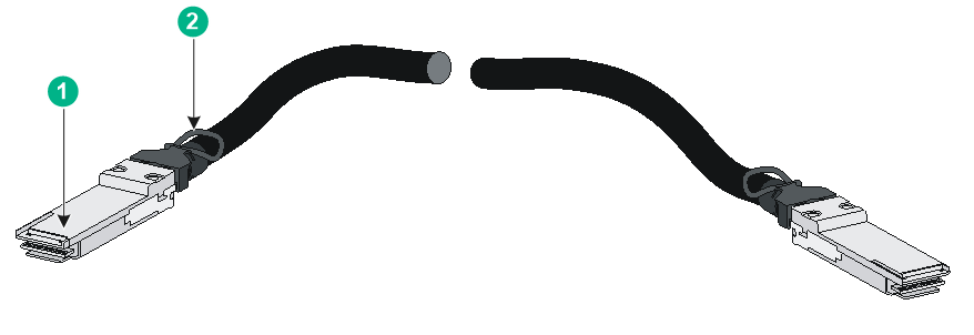
|
(1) Connector |
(2) Pull tab |
|
|
NOTE: · As a best practice, use H3C transceiver modules and cables for the switch. · The H3C transceiver modules and cables are subject to change over time. For the most recent list of H3C transceiver modules and cables, contact your H3C Support or marketing staff. · For more information about H3C transceiver modules and cables, see H3C Transceiver Modules User Guide. |
10/100/1000BASE-T Ethernet port
Table7-19 10/100/1000BASE-T Ethernet port specifications
|
Item |
Specification |
|
Connector type |
RJ-45 |
|
Rate, duplex mode, and auto-MDI/MDI-X |
· 10 Mbps, half/full duplex · 100 Mbps, half/full duplex · 1000 Mbps, full duplex · MDI/MDI-X autosensing |
|
Max transmission distance |
100 m (328.08 ft) |
|
Transmission medium |
Category 5 or above twisted pair cable |
|
Compliant standard |
IEEE 802.3i, 802.3u, and 802.3ab |
|
Compatible devices |
All device models (excluding the S5590-48S4XC-HI and S5590-48S4XC-EI switches) |
10G/5G/2.5G/1000BASE-T autosensing Ethernet port
Table7-20 10G/5G/2.5G/1000BASE-T autosensing Ethernet port specifications
|
Item |
Specification |
|
Connector type |
RJ-45 |
|
Rate, duplex mode, and auto-MDI/MDI-X |
· 5 Gbps, full duplex · 2.5 Gbps, full duplex · 1 Gbps, full duplex · 100 Mbps, full duplex · 10 Mbps, full duplex · MDI/MDI-X autosensing |
|
Max transmission distance |
10G mode: · 55 m (180.45 ft) over Category-6 unshielded twisted pair cable · 100 m (328.08 ft) over Category-6 shielded twisted pair cable · 100 m (328.08 ft) over Category-6e twisted pair cable 5G mode: · 55 m (180.45 ft) over Category-5e unshielded twisted pair cable · 100 m (328.08 ft) over Category-5e shielded twisted pair cable · 100 m (328.08 ft) over Category-6 twisted pair cable · 100 m (328.08 ft) over Category-6e twisted pair cable 2.5G mode: 100 m (328.08 ft) over Category-5e or above twisted pair cable 1G/100M/10M mode: 100 m (328.08 ft) over Category-5 or above twisted pair cable |
|
Transmission medium |
Category-5 or above twisted pair cable |
|
Compliant standard |
IEEE 802.3an and IEEE 802.3ab |
|
Compatible devices |
S5590-24UXM4YC-EI, S5590-48UXM4YC-EI |
Combo interface
The S5590-28T8XC-HI, S5590-28S8XC-HI, S5590-28T8XC-EI, S5590-28S8XC-EI, and S5590-28P8XC-EI switches each provide four combo interfaces on the front panel. A combo interface contains an SFP port and a 10/100/1000BASE-T autosensing Ethernet port. Only one of these two ports can operate at a time.
Ports on an LSWM2EC EPS scanner module
Table7-21 Console port specifications
|
Item |
Specification |
|
Connector type |
RJ-45 |
|
Compliant standard |
EIA/TIA-232 |
|
Port transmission rate |
115200 bps |
|
Transmission medium and max transmission distance |
≤ 15 m (49.21 ft) over a common asynchronous serial interface cable |
|
Services |
· Provides connection to an ASCII terminal · Provides connection to the serial port of a local PC running terminal emulation program |
Table7-22 Management Ethernet port specifications
|
Item |
Specification |
|
Connector type |
RJ-45 |
|
Port transmission rate |
· 1000 Mbps, full duplex · 100 Mbps, full duplex · 10 Mbps, full duplex |
|
MDI/MDI-X autosensing |
Supported |
|
Transmission medium |
Category-5 or above twisted pair cable |
|
Max transmission distance |
100 m (328.08 ft) |
|
Compliant standard |
IEEE 802.3i, 802.3u, and 802.3ab |
|
Functions and services |
Connects to a local PC or remote station for network management or software upgrade |
Table7-23 USB port specifications
|
Item |
Specification |
|
Port type |
USB 3.0 |
|
Compliant standard |
xHCI |
|
Port transmission rate |
5 Gbps |
|
Functions and services |
Uploads or downloads files, such as software image file and configuration file, from the flash file system on the module. |
Ports on an LSPM6FWD firewall module
Table7-24 Console port specifications
|
Item |
Specification |
|
Connector type |
RJ-45 |
|
Compliant standard |
RS-232 |
|
Port transmission rate |
9600 bps (default) to 115200 bps |
|
Transmission medium and max transmission distance |
≤ 15 m (49.21 ft) over a common asynchronous serial interface cable |
|
Services |
· Provides connection to an ASCII terminal · Provides connection to the serial port of a local PC running terminal emulation program · Supports command line interface (CLI) |
Table7-25 10/100/1000BASE-T Ethernet copper port specifications
|
Item |
Specification |
|
Connector type |
RJ-45 |
|
Compliant standard |
802.3, 802.3u, and 802.3ab |
|
Port type |
MDI/MDI-X autosensing |
|
Transmission medium |
Category-5 or above twisted pair cable |
|
Transmission distance |
100 m (328.08 ft) |
|
Rate and duplex mode |
· 10 Mbps, half/full duplex · 100 Mbps, half/full duplex · 1000 Mbps, full duplex |
Connecting cables to the ports on expansion cards
To connect cables to the ports on expansion cards, follow these guidelines:
· Do not bundle cables in their first 20 m (65.62 ft).
· Separate power cords and twisted pair cables at and around the distribution frame.
· For ports adjacent to one another on the device, the peer ports on the distribution frame is preferably not adjacent, for example:
¡ If the device connects to one distribution frame, connect port 1 on the device to port 1 on the distribution frame and port 2 on the device to port 3 on the distribution frame.
¡ If the device connects to two distribution frames, connect port 1 on the device to port 1 on distribution frame 1 and port 2 on the device to port 1 on distribution frame 2.
· Keep the device and cables away from the interference source, such as a two-way radio and a high-power variable-frequency drive.
LEDs
System status LED
The system status LED shows the operating status of the switch.
Table7-26 System status LED description
|
LED mark |
Status |
Description |
|
SYS |
Steady green |
The switch has started correctly. |
|
Flashing green (1 Hz) |
The switch is performing power-on self test (POST). |
|
|
Steady red |
The switch has failed the POST or is faulty. |
|
|
Off |
The switch is powered off. |
Power status LED
For the S5590-EI switch series, the power status LED shows the operating status of a power supply.
Table7-27 Power status LED description
|
LED mark |
Status |
Description |
|
PWR1/PWR2 |
Steady green |
The power supply is operating correctly. |
|
Steady yellow |
The power supply is present, but it is not operating or is faulty. |
|
|
Off |
No power supply is present. |
Mode LED
The mode LED (MODE) works in conjunction with the port status LEDs to show more information about the switch.
The mode LED indicates the type of information that the port status LEDs are showing.
After you press the mode button to change the mode LED status into flashing green or flashing yellow, the mode LED keeps in that state for only 45 seconds and then turns steady green automatically.
Table7-28 Mode LED description
|
LED mark |
Status |
Description |
|
MODE |
Steady green |
The port status LEDs indicate link state of the ports. |
|
Flashing green (available only for PoE switches) |
The port status LEDs indicate the PoE status of the ports. |
|
|
Flashing yellow |
The port status LEDs indicate the IRF member ID of the switch. For example, if the LEDs for ports 1 to 4 are steady green and the others are off, the IRF member ID of the switch is 4. |
Management Ethernet port LED
Table7-29 Management Ethernet port LED description
|
Management Ethernet port LED status |
Description |
|
Steady green |
A link is present on the port. |
|
Flashing yellow |
The port is sending or receiving data. |
|
Off |
No link is present on the port. |
SFP port LED
The SFP port LEDs work in conjunction and the mode LED to indicate the operating status of SFP ports.
Table7-30 SFP port LED description
|
Mode LED (MODE) status |
SFP port LED status |
Description |
|
Steady green (rate mode) |
Steady green |
The port is operating at 100/1000 Mbps. |
|
Flashing green |
The port is sending or receiving data at 100/1000 Mbps. |
|
|
Off |
No link is present on the port. |
|
|
Flashing yellow (IRF mode) |
Steady green |
The SFP port LEDs on the switch work in conjunction to indicate the IRF member ID of the switch. For example, if the LEDs for ports 1 to 4 are steady green and the others are off, the IRF member ID of the switch is 4. |
SFP+ port LED
Table7-31 SFP+ port LED description
|
Mode LED status |
SFP+ port LED status |
Description |
|
Steady green (rate mode) |
Steady green |
The port is operating at 10 Gbps. |
|
Flashing green |
The port is sending or receiving data at 10 Gbps. |
|
|
Steady yellow |
The port is operating at 1 Gbps. |
|
|
Flashing yellow |
The port is sending or receiving data at 1 Gbps. |
|
|
Off |
No link is present on the port. |
|
|
Flashing green (PoE mode, available only for PoE switches) |
Off |
The mode LED (MODE) is operating in PoE mode. |
|
Flashing yellow (IRF mode) |
Off |
When the mode LED (MODE) is flashing yellow (IRF mode), the SFP+ port LEDs are off. |
SFP28 port LED
Table7-32 SFP28 port LED description
|
LED status |
Description |
|
Steady green |
The port is operating at 25 Gbps. |
|
Flashing green |
The port is sending or receiving data at 25 Gbps. |
|
Steady yellow |
The port is operating at 10 Gbps. |
|
Flashing yellow |
The port is sending or receiving data at 10 Gbps. |
|
Off |
· No module has been installed or no link is present on the port. · The mode LED is operating in PoE mode (available only for PoE switch models). |
QSFP+ port LED
Table7-33 QSFP+ port LED description
|
LED status |
Description |
|
Steady green |
A module has been installed and the port is operating at 40 Gbps. |
|
Flashing green |
The port is sending or receiving data at 40 Gbps. |
|
Steady yellow |
A module has been installed and the port is operating at 10 Gbps. |
|
Flashing yellow |
The port is sending or receiving data at 10 Gbps. |
|
Off |
No module has been installed or no link is present on the port. |
QSFP28 port LED
Table7-34 QSFP28 port LED description
|
LED status |
Description |
|
Steady green |
A module has been installed and the port is operating at 100 Gbps. |
|
Flashing green |
The port is sending or receiving data at 100 Gbps. |
|
Steady yellow |
A module has been installed and the port is operating at 40 Gbps. |
|
Flashing yellow |
The port is sending or receiving data at 40 Gbps. |
|
Off |
No module has been installed or no link is present on the port. |
10/100/1000BASE-T autosensing Ethernet port LED
The 10/100/1000BASE-T autosensing Ethernet port LEDs work in conjunction with the mode LED to indicate the operating status of the ports from different aspects, as shown in Table7-35.
Table7-35 10/100/1000BASE-T autosensing Ethernet port LED description
|
Mode LED (MODE) status |
Ethernet port LED status |
Description |
|
Steady green (rate mode) |
Steady green |
The port is operating at 10/100/1000 Mbps. |
|
Flashing green |
The port is sending or receiving data at 10/100/1000 Mbps. |
|
|
Off |
No link is present on the port. |
|
|
Flashing green (PoE mode, available only for PoE switches) |
Steady green |
PoE power supply is normal. |
|
Flashing green (1 Hz) |
· The maximum PoE power provided by the port does not meet the power requirement of the PD. · PoE power supply overcurrent, overvoltage, or short-circuit has occurred. · The remaining power of the switch does not meet the power supply requirement of the port. |
|
|
Off |
The port is not connected to a PD or PoE is not enabled on the port. |
|
|
Flashing yellow (IRF mode) |
Steady green |
The autosensing Ethernet port LEDs on the switch work in conjunction to indicate the IRF member ID of the switch. For example, if the LEDs for ports 1 to 4 are steady green and the others are off, the IRF member ID of the switch is 4. |
10G/5G/2.5G/1000BASE autosensing Ethernet port LED
Table7-36 10G/5G/2.5G/1000BASE autosensing Ethernet port LED description
|
LED status |
Description |
|
Steady green |
The port is operating at 10 Gbps. |
|
Flashing green |
The port is sending or receiving data at 10 Gbps. |
|
Steady yellow |
The port is operating at 10Mbps, 100Mbps, 1 Gbps, 2.5 Gbps, or 5 Gbps. |
|
Flashing yellow |
The port is sending or receiving data at 10Mbps, 100Mbps, 1 Gbps, 2.5 Gbps, or 5 Gbps. |
|
Off |
No link is present on the port. |
Expansion card status LED
The S5590-HI switch series provides two expansion slots at the rear. The S5590-EI switch series provides one expansion slot at the rear. The expansion card status LED on the front panel indicates the operating status of the expansion card.
Table7-37 Expansion card status LED description
|
LED mark |
Status |
Description |
|
SLOT/SLOT1/SLOT2 |
Steady green |
The expansion card is operating correctly. |
|
Flashing yellow |
The switch does not support the expansion card model, or the expansion card is faulty. |
|
|
Off |
The expansion slot is empty. |
Fan tray status LED on a fan tray
The LSPM1FANSA-SN and LSPM1FANSB-SN fan trays each have a LED to indicate the fan tray operating status.
Table7-38 Fan tray status LED description
|
Status |
Description |
|
On |
The fan tray is faulty. |
|
Off |
The fan tray is operating correctly. |
Status LED on a PSR250-12A/PSR250-12A1 power supply
The PSR250-12A and PSR250-12A1 power supplies each have a LED to indicate the power input and output status.
Table7-39 Description for the status LED on a PSR250-12A/PSR250-12A1 power supply
|
LED status |
Description |
|
Steady green |
The power supply is operating correctly in active state. |
|
Flashing green |
The power supply is operating correctly in standby state. |
|
Steady red |
The power supply has failed or entered protection state. |
|
Red/Green flashing alternatively |
The power supply has an output overvoltage, output undervoltage, output overcurrent, output overload, or overtemperature alarm but has not entered protection state. |
|
Flashing red |
The power supply does not have power input. If two power supplies are installed and only one power supply has power input, the status LED of the power supply that does not have power input flashes red. |
|
Off |
The power supply does not have power input. |
Status LEDs on a 600W/920W/1600W power supply
The PSR600-54A-B, PSR920-54A-B, and PSR1600-54A-B power supplies each have two status LEDs to indicate the power input and output status.
Table7-40 Description for the status LEDs on a 600W/920W/1600W power supply
|
LED |
Mark |
Status |
Description |
|
Output status LED |
OUT OK |
Steady green |
Normal power output. |
|
Steady red |
Abnormal power output. |
||
|
Off |
No power output |
||
|
Input status LED |
IN OK |
Steady green |
Normal power input. |
|
Steady red |
Abnormal power input. |
||
|
Off |
No power input. |
LEDs on an LSWM2SP8P/LSWM2SP8PM interface card
The LSWM2SP8P and LSWM2SP8PM interface cards each provide eight SFP+ ports.
Table7-41 SFP+ port LED description
|
LED status |
Description |
|
Steady green |
A module has been installed and the port is operating at 10 Gbps. |
|
Flashing green |
The port is sending or receiving data at 10 Gbps. |
|
Steady yellow |
A module has been installed and the port is operating at 1 Gbps. |
|
Flashing yellow |
The port is sending or receiving data at 1 Gbps. |
|
Off |
No module has been installed or no link is present on the port. |
LEDs on an LSWM2EC EPS scanner module
Table7-42 Management port LED description
|
LED status |
Description |
|
Steady green |
The port is operating at 1000/100/10 Mbps. |
|
Flashing green |
The port is sending or receiving data at 1000/100/10 Mbps. |
|
Off |
No link is present on the port. |
LEDs on an LSPM6FWD firewall module
Table7-43 Description for the LEDs on an LSPM6FWD firewall module
|
LED |
Mark |
Status |
Description |
|
Management Ethernet port LED |
ACT/LINK |
Off |
No link is present on the port. |
|
Steady green |
A link is present on the port. |
||
|
Flashing green |
The port is sending or receiving data. |
||
|
System status LED |
SYS |
Off |
No power is input or the firewall module has failed. |
|
Slowly flashing green |
The system has started up and is operating correctly. |
||
|
Fast flashing green |
The system is loading software. |
8 Cooling system
To dissipate heat timely and enhance system stability, the switch uses a high-performance cooling system. Consider the site ventilation design when you plan the installation site for the switch.
The switch uses removable fan trays and provides airflow from the port side to the power supply side or from the power supply side to the port side by using different types of fan trays. You must install both fan trays of the same model for the switch. Table8-1 describes the fan trays available for the switch.
Table8-1 Fan trays available for the switch
|
Switch model |
Fan tray model |
Airflow direction |
|
S5590-28T8XC-HI S5590-48T4XC-HI S5590-28S8XC-HI S5590-48S4XC-HI S5590-28T8XC-EI S5590-48T4XC-EI S5590-28S8XC-EI S5590-48S4XC-EI S5590-28P8XC-EI S5590-48P6XC-EI S5590-24X4YC-EI S5590-48TS4X2QC-EI |
LSPM1FANSA-SN |
From the power supply side to the port side |
|
LSPM1FANSB-SN |
From the port side to the power supply side |
|
|
S5590-24UXM4YC-EI S5590-48UXM4YC-EI |
LSPM1FANSB-SN |
From the port side to the power supply side |
Figure8-1 Airflow direction for LSPM1FANSA-SN (S5590-28P8XC-EI)
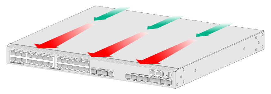
Figure8-2 Airflow direction for LSPM1FANSB-SN (S5590-28P8XC-EI)