- Table of Contents
-
- H3C MSR1000[2600][3600] Routers Configuration Examples All-in-One-R9141-6W100
- 00-Preface
- 01-Local 802.1X Authentication Configuration Examples
- 02-RADIUS-Based 802.1X Authentication Configuration Examples
- 03-AAA Configuration Examples
- 04-ACL Configuration Examples
- 05-MPLS over ADVPN Configuration Examples
- 06-ARP Attack Protection Configuration Examples
- 07-BFD Configuration Examples
- 08-Basic BGP Configuration Examples
- 09-BGP Route Attribute-Based Route Selection Configuration Examples
- 10-EAA Monitor Policy Configuration Examples
- 11-GRE with OSPF Configuration Examples
- 12-HoVPN Configuration Examples
- 13-IGMP Snooping Configuration Examples
- 14-IGMP Configuration Examples
- 15-IPsec Configuration Examples
- 16-IPsec Digital Certificate Authentication Configuration Examples
- 17-IPv6 IS-IS Configuration Examples
- 18-IPv6 over IPv4 GRE Tunnel Configuration Examples
- 19-IPv6 over IPv4 Manual Tunnel with OSPFv3 Configuration Examples
- 20-IS-IS Configuration Examples
- 21-Combined ISATAP Tunnel and 6to4 Tunnel Configuration Examples
- 22-L2TP over IPsec Configuration Examples
- 23-Multi-Instance L2TP Configuration Examples
- 24-L2TP Multidomain Access Configuration Examples
- 25-MPLS L3VPN Configuration Examples
- 26-MPLS OAM Configuration Examples
- 27-MPLS TE Configuration Examples
- 28-Basic MPLS Configuration Examples
- 29-NAT DNS Mapping Configuration Examples
- 30-NetStream Configuration Examples
- 31-NQA Configuration Examples
- 32-NTP Configuration Examples
- 33-OSPFv3 Configuration Examples
- 34-OSPF Configuration Examples
- 35-OSPF Multi-Process Configuration Examples
- 36-OSPF Multi-Instance Configuration Examples
- 37-Portal Configuration Examples
- 38-PPP Configuration Examples
- 39-RBAC Configuration Examples
- 40-RMON Configuration Examples
- 41-IPv4 NetStream Sampling Configuration Examples
- 42-SNMP Configuration Examples
- 43-SRv6 Configuration Examples
- 44-SSH Configuration Examples
- 45-Tcl Commands Configuration Examples
- 46-VLAN Configuration Examples
- 47-VRRP Configuration Examples
- 48-VXLAN over IPsec Configuration Examples
- 49-WLAN AC Configuration Examples
- 50-Small and Medium-Sized Store Configuration Examples
- 51-Cloudnet VPN Configuration Examples
- 52-Ethernet Link Aggregation Configuration Examples
- 53-Ethernet OAM Configuration Examples
- 54-Outbound Bidirectional NAT Configuration Examples
- 55-NAT Hairpin in C-S Mode Configuration Examples
- 56-Load Sharing NAT Server Configuration Examples
- 57-BIDIR-PIM Configuration Examples
- 58-Control Plane-Based QoS Policy Configuration Examples
- 59-Scheduling a Task Configuration Examples
- 60-Client-Initiated L2TP Tunnel Configuration Examples
- 61-LAC-Auto-Initiated L2TP Tunnel Configuration Examples
- 62-Authorized ARP Configuration Examples
- 63-GTS Configuration Examples
- 64-Traffic Policing Configuration Examples
- 65-Traffic Accounting Configuration Examples
- 66-Mobile Communication Modem Management Configuration Examples
- 67-Port Isolation Configuration Examples
- 68-PBR Configuration Examples
- 69-TFTP Client Software Upgrade Configuration Examples
- 70-FTP Client Software Upgrade Configuration Examples
- 71-FTP Server Software Upgrade Configuration Examples
- 72-Routing Policy Configuration Examples
- 73-Software Upgrade from the BootWare Menu Configuration Examples
- 74-Mirroring Configuration Examples
- Related Documents
-
| Title | Size | Download |
|---|---|---|
| 08-Basic BGP Configuration Examples | 189.47 KB |
Basic BGP Configuration Examples
Copyright © 2024 New H3C Technologies Co., Ltd. All rights reserved.
No part of this manual may be reproduced or transmitted in any form or by any means without prior written consent of New H3C Technologies Co., Ltd.
Except for the trademarks of New H3C Technologies Co., Ltd., any trademarks that may be mentioned in this document are the property of their respective owners.
The information in this document is subject to change without notice.
Contents
Example: Configuring basic BGP
Configuring IP addresses for interfaces
Configure Router B to advertise the routes to local networks
Examples: Configuring BGP and IGP route redistribution
Configuring IP addresses for interfaces
Configuring BGP and IGP route redistribution:
Introduction
This document provides basic BGP configuration examples.
Prerequisites
The following information applies to Comware 9-based routers. Procedures and information in the examples might be slightly different depending on the software or hardware version of the routers.
The configuration examples were created and verified in a lab environment, and all the devices were started with the factory default configuration. When you are working on a live network, make sure you understand the potential impact of every command on your network.
The following information is provided based on the assumption that you have basic knowledge of BGP.
Example: Configuring basic BGP
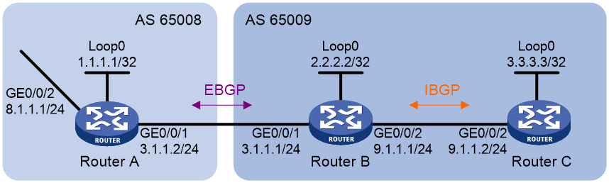
Network configuration
As shown in Figure 1, all routers run BGP. Run EBGP between Router A and Router B, and run IBGP between Router B and Router C so that Router C can access subnet 8.1.1.0/24, which is connected to Router A.
Analysis
By default, BGP does not advertise local networks. To enable Router C to access subnet 8.1.1.0/24 connected directly to Router A, perform the following tasks:
· Add network 8.1.1.0/24 to the BGP routing table of Router A.
· Add networks 3.1.1.0/24 and 9.1.1.0/24 to the BGP routing table of Router B.
Software versions used
This configuration example was created and verified on R9141P16 of the MSR2630E-X1 device.
Restrictions and guidelines
When you configure basic BGP, follow these restrictions and guidelines:
· Use loopback interfaces to establish IBGP connections to prevent route flapping caused by port state changes.
· Loopback interfaces are virtual interfaces. Use the peer connect-interface command to specify the loopback interface as the source interface for establishing BGP connections.
· The EBGP peers, Router A and Router B, are located in different ASs. Typically, their loopback interfaces are not reachable to each other, so the routers use directly connected interfaces to establish EBGP sessions.
Procedures
Configuring IP addresses for interfaces
# Configure IP addresses for Loopback 0, GigabitEthernet 1/0/1, and GigabitEthernet 1/0/2 on Router A.
<RouterA> system-view
[RouterA] interface loopback 0
[RouterA-LoopBack0] ip address 1.1.1.1 255.255.255.255
[RouterA-LoopBack0] quit
[RouterA] interface gigabitethernet 1/0/1
[RouterA-GigabitEthernet1/0/1] port link-mode route
[RouterA-GigabitEthernet1/0/1] ip address 3.1.1.2 255.255.255.0
[RouterA-GigabitEthernet1/0/1] quit
[RouterA] interface gigabitethernet 1/0/2
[RouterA-GigabitEthernet1/0/2] port link-mode route
[RouterA-GigabitEthernet1/0/2] ip address 8.1.1.1 255.255.255.0
[RouterA-GigabitEthernet1/0/2] quit
# Configure IP addresses for Loopback 0, GigabitEthernet 1/0/1, and GigabitEthernet 1/0/2 on Router B.
<RouterB> system-view
[RouterB] interface loopback 0
[RouterB-LoopBack0] ip address 2.2.2.2 255.255.255.255
[RouterB-LoopBack0] quit
[RouterB] interface gigabitethernet 1/0/1
[RouterB-GigabitEthernet1/0/1] port link-mode route
[RouterB-GigabitEthernet1/0/1] ip address 3.1.1.1 255.255.255.0
[RouterB-GigabitEthernet1/0/1] quit
[RouterB] interface gigabitethernet 1/0/2
[RouterB-GigabitEthernet1/0/2] port link-mode route
[RouterB-GigabitEthernet1/0/2] ip address 9.1.1.1 255.255.255.0
[RouterB-GigabitEthernet1/0/2] quit
# Configure IP addresses for Loopback 0 and GigabitEthernet 1/0/2 on Router C.
<RouterC> system-view
[RouterC] interface loopback 0
[RouterC-LoopBack0] ip address 3.3.3.3 255.255.255.255
[RouterC-LoopBack0] quit
[RouterC] interface gigabitethernet 1/0/2
[RouterC-GigabitEthernet1/0/2] port link-mode route
[RouterC-GigabitEthernet1/0/2] ip address 9.1.1.2 255.255.255.0
[RouterC-GigabitEthernet1/0/2] quit
Configuring IBGP
1. Configure Router B.
# Set the router ID of Router B to 2.2.2.2 in BGP view.
[RouterB] bgp 65009
[RouterB-bgp] router-id 2.2.2.2
# Create IBGP peer 3.3.3.3, and then specify Loopback 0 as the source interface for TCP connection to the IBGP peer.
[RouterB-bgp] peer 3.3.3.3 as-number 65009
[RouterB-bgp] peer 3.3.3.3 connect-interface loopback 0
# Create and enter BGP IPv4 unicast address family view, and then enable Router B to exchange IPv4 unicast routing information with peer 3.3.3.3.
[RouterB-bgp] address-family ipv4 unicast
[RouterB-bgp-ipv4] peer 3.3.3.3 enable
[RouterB-bgp-ipv4] quit
[RouterB-bgp] quit
# Configure OSPF settings on Router B.
[RouterB] ospf 1
[RouterB-ospf-1] area 0
[RouterB-ospf-1-area-0.0.0.0] network 2.2.2.2 0.0.0.0
[RouterB-ospf-1-area-0.0.0.0] network 9.1.1.0 0.0.0.255
[RouterB-ospf-1-area-0.0.0.0] quit
[RouterB-ospf-1] quit
2. Configure Router C.
# Set the router ID of Router C to 3.3.3.3 in BGP view.
[RouterC] bgp 65009
[RouterC-bgp] router-id 3.3.3.3
# Create IBGP peer 2.2.2.2, and then specify Loopback 0 as the source interface for TCP connection to the IBGP peer.
[RouterC-bgp] peer 2.2.2.2 as-number 65009
[RouterC-bgp] peer 2.2.2.2 connect-interface loopback 0
# Create and enter BGP IPv4 unicast address family view, and then enable Router B to exchange IPv4 unicast routing information with peer 2.2.2.2.
[RouterC-bgp] address-family ipv4 unicast
[RouterC-bgp-ipv4] peer 2.2.2.2 enable
[RouterC-bgp-ipv4] quit
[RouterC-bgp] quit
# Configure OSPF settings on Router B.
[RouterC] ospf 1
[RouterC-ospf-1] area 0
[RouterC-ospf-1-area-0.0.0.0] network 3.3.3.3 0.0.0.0
[RouterC-ospf-1-area-0.0.0.0] network 9.1.1.0 0.0.0.255
[RouterC-ospf-1-area-0.0.0.0] quit
[RouterC-ospf-1] quit
3. Verify that Router B and Router C has established an IBGP peer relationship.
# Display brief information about all BGP IPv4 unicast peers on Router C.
[RouterC] display bgp peer ipv4
BGP local router ID : 3.3.3.3
Local AS number : 65009
Total number of peers : 1 Peers in established state : 1
Peer AS MsgRcvd MsgSent OutQ PrefRcv Up/Down State
2.2.2.2 65009 2 2 0 0 00:00:13 Established
The command output shows that Router B and Router C has established an IBGP peer relationship.
Configuring EBGP
1. Configure Router A.
# Set the router ID of Router A to 1.1.1.1 in BGP view.
[RouterA] bgp 65008
[RouterA-bgp] router-id 1.1.1.1
# Create EBGP peer 3.1.1.1 in BGP view and set the AS number of the peer to 65009.
[RouterA-bgp] peer 3.1.1.1 as-number 65009
# Create and enter BGP IPv4 unicast address family view, and then enable Router A to exchange IPv4 unicast routing information with peer 3.1.1.1.
[RouterA-bgp] address-family ipv4 unicast
[RouterA-bgp-ipv4] peer 3.1.1.1 enable
# Add route 8.1.1.0/24 to the BGP routing table.
[RouterA-bgp-ipv4] network 8.1.1.0 24
[RouterA-bgp-ipv4] quit
[RouterA-bgp] quit
2. Configure Router B.
# Create EBGP peer 3.1.1.2 in BGP view and set the AS number of the peer to 65008.
[RouterB] bgp 65009
[RouterB-bgp] peer 3.1.1.2 as-number 65008
# Create and enter BGP IPv4 unicast address family view, and then enable Router B to exchange IPv4 unicast routing information with peer 3.1.1.2.
[RouterB-bgp] address-family ipv4 unicast
[RouterB-bgp-ipv4] peer 3.1.1.2 enable
[RouterB-bgp-ipv4] quit
[RouterB-bgp] quit
3. Verify the EBGP configuration.
# Display BGP peer information on Router B.
[RouterB] display bgp peer ipv4
BGP local router ID : 2.2.2.2
Local AS number : 65009
Total number of peers : 2 Peers in established state : 2
Peer AS MsgRcvd MsgSent OutQ PrefRcv Up/Down State
3.3.3.3 65009 4 4 0 0 00:02:49 Established
3.1.1.2 65008 2 2 0 0 00:00:05 Established
The command output shows that Router B has established an IBGP peer relationship with Router C and an EBGP peer relationship with Router A.
# Display the BGP routing table on Router A.
[RouterA] display bgp routing-table ipv4
Total number of routes: 1
BGP local router ID is 1.1.1.1
Status codes: * - valid, > - best, d - dampened, h - history,
s - suppressed, S - stale, i - internal, e - external
Origin: i - IGP, e - EGP, ? – incomplete
Network NextHop MED LocPrf PrefVal Path/Ogn
* > 8.1.1.0/24 8.1.1.1 0 32768 i
# Display the BGP routing table on Router B.
[RouterB] display bgp routing-table ipv4
Total number of routes: 1
BGP local router ID is 2.2.2.2
Status codes: * - valid, > - best, d - dampened, h - history,
s - suppressed, S - stale, i - internal, e - external
Origin: i - IGP, e - EGP, ? – incomplete
Network NextHop MED LocPrf PrefVal Path/Ogn
* >e 8.1.1.0/24 3.1.1.2 0 0 65008i
# Display the BGP routing table on Router C.
[RouterC] display bgp routing-table ipv4
Total number of routes: 1
BGP local router ID is 3.3.3.3
Status codes: * - valid, > - best, d - dampened, h - history,
s - suppressed, S - stale, i - internal, e - external
Origin: i - IGP, e - EGP, ? – incomplete
Network NextHop MED LocPrf PrefVal Path/Ogn
i 8.1.1.0/24 3.1.1.2 0 100 0 65008i
According to the command outputs:
¡ Router A has learned no route to AS 65009.
¡ Router C has learned a route to subnet 8.1.1.0, but the next hop 3.1.1.2 is unreachable. As a result, the route is invalid.
Configure Router B to advertise the routes to local networks
# Create and enter BGP IPv4 unicast address family view.
[RouterB] bgp 65009
[RouterB-bgp] address-family ipv4 unicast
# Configure BGP to advertise the routes to local networks, so that Router A can obtain route 9.1.1.0/24 and Router C can obtain route 3.1.1.0/24.
[RouterB-bgp-ipv4] network 3.1.1.0 24
[RouterB-bgp-ipv4] network 9.1.1.0 24
[RouterB-bgp-ipv4] quit
[RouterB-bgp] quit
# Display the BGP routing table on Router A.
[RouterA] display bgp routing-table ipv4
Total number of routes: 3
BGP local router ID is 1.1.1.1
Status codes: * - valid, > - best, d - dampened, h - history,
s - suppressed, S - stale, i - internal, e - external
Origin: i - IGP, e - EGP, ? – incomplete
Network NextHop MED LocPrf PrefVal Path/Ogn
* >e 3.1.1.0/24 3.1.1.1 0 0 65009?
* > 8.1.1.0/24 8.1.1.1 0 32768 i
* >e 9.1.1.0/24 3.1.1.1 0 0 65009i
The command output shows that route 9.1.1.0/24 has been added in Router A's routing table.
# Display the BGP routing table on Router C.
[RouterC] display bgp routing-table ipv4
Total number of routes: 3
BGP local router ID is 3.3.3.3
Status codes: * - valid, > - best, d - dampened, h - history,
s - suppressed, S - stale, i - internal, e - external
Origin: i - IGP, e - EGP, ? – incomplete
Network NextHop MED LocPrf PrefVal Path/Ogn
* >i 3.1.1.0/24 2.2.2.2 0 100 0 ?
* >i 8.1.1.0/24 3.1.1.2 0 100 0 65008i
* >i 9.1.1.0/24 2.2.2.2 0 100 0 i
The output shows that route 8.1.1.0 becomes valid and its next hop is Router A.
Verifying the configuration
# Use the ping command to verify that Router C can reach 8.1.1.1.
[RouterC] ping 8.1.1.1
Ping 8.1.1.1 (8.1.1.1): 56 data bytes, press CTRL_C to break
56 bytes from 8.1.1.1: icmp_seq=0 ttl=254 time=10.000 ms
56 bytes from 8.1.1.1: icmp_seq=1 ttl=254 time=4.000 ms
56 bytes from 8.1.1.1: icmp_seq=2 ttl=254 time=4.000 ms
56 bytes from 8.1.1.1: icmp_seq=3 ttl=254 time=3.000 ms
56 bytes from 8.1.1.1: icmp_seq=4 ttl=254 time=3.000 ms
--- Ping statistics for 8.1.1.1 ---
5 packet(s) transmitted, 5 packet(s) received, 0.0% packet loss
round-trip min/avg/max/std-dev = 3.000/4.800/10.000/2.638 ms
The command output shows that Router C can reach subnet 8.1.1.0/24.
Configuration files
Router A
#
interface Loopback0
ip address 1.1.1.1 255.255.255.255
#
interface GigabitEthernet1/0/1
ip address 3.1.1.2 255.255.255.0
#
interface GigabitEthernet1/0/2
ip address 8.1.1.1 255.255.255.0
#
bgp 65008
router-id 1.1.1.1
peer 3.1.1.1 as-number 65009
#
address-family ipv4 unicast
network 8.1.1.0 255.255.255.0
peer 3.1.1.1 enable
#
Router B
#
interface Loopback0
ip address 2.2.2.2 255.255.255.255
#
interface GigabitEthernet1/0/1
ip address 3.1.1.1 255.255.255.0
#
interface GigabitEthernet1/0/2
ip address 9.1.1.1 255.255.255.0
#
bgp 65009
router-id 2.2.2.2
peer 3.1.1.2 as-number 65008
peer 3.3.3.3 as-number 65009
peer 3.3.3.3 connect-interface Loopback0
#
address-family ipv4 unicast
network 3.1.1.0 24
network 9.1.1.0 24
peer 3.1.1.2 enable
peer 3.3.3.3 enable
#
ospf 1
area 0.0.0.0
network 2.2.2.2 0.0.0.0
network 9.1.1.0 0.0.0.255
#
Router C
#
interface Loopback0
ip address 3.3.3.3 255.255.255.255
#
interface GigabitEthernet1/0/2
ip address 9.1.1.2 255.255.255.0
#
bgp 65009
router-id 3.3.3.3
peer 2.2.2.2 as-number 65009
peer 2.2.2.2 connect-interface Loopback0
#
address-family ipv4 unicast
peer 2.2.2.2 enable
#
ospf 1
area 0.0.0.0
network 3.3.3.3 0.0.0.0
network 9.1.1.0 0.0.0.255
#
Examples: Configuring BGP and IGP route redistribution
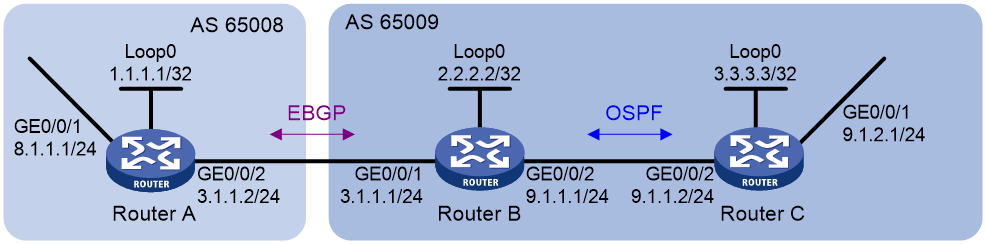
Network configuration
As shown in Figure 2, run EBGP between Router A and Router B, and run OSPF between Router B and Router C to allow communication only between subnets 9.1.2.0/24 and 8.1.1.0/24.
Analysis
To enable Router B to communicate with Router C through loopback interfaces, enable OSPF in AS 65009.
To enable Router A to obtain the route to 9.1.2.0/24, configure BGP to redistribute routes from OSPF on Router B. To enable Router C to obtain the route to 8.1.1.0/24, configure OSPF to redistribute routes from BGP on Router B.
Software versions used
This configuration example was created and verified on R9141P16 of the MSR2630E-X1 device.
Restrictions and guidelines
· Use loopback interfaces to establish IBGP connections to prevent route flapping caused by port state changes.
· Loopback interfaces are virtual interfaces. Use the peer connect-interface command to specify the loopback interface as the source interface for establishing BGP connections.
· The EBGP peers, Router A and Router B, are located in different ASs. Typically, their loopback interfaces are not reachable to each other, so the routers use directly connected interfaces to establish EBGP sessions.
Procedures
Configuring IP addresses for interfaces
# Configure IP addresses for Loopback 0, GigabitEthernet 1/0/1, and GigabitEthernet 1/0/2 on Router A.
<RouterA> system-view
[RouterA] interface loopback 0
[RouterA-LoopBack0] ip address 1.1.1.1 255.255.255.255
[RouterA-LoopBack0] quit
[RouterA] interface gigabitethernet 1/0/1
[RouterA-GigabitEthernet1/0/1] port link-mode route
[RouterA-GigabitEthernet1/0/1] ip address 8.1.1.1 255.255.255.0
[RouterA-GigabitEthernet1/0/1] quit
[RouterA] interface gigabitethernet 1/0/2
[RouterA-GigabitEthernet1/0/2] port link-mode route
[RouterA-GigabitEthernet1/0/2] ip address 3.1.1.2 255.255.255.0
[RouterA-GigabitEthernet1/0/2] quit
# Configure IP addresses for Loopback 0, GigabitEthernet 1/0/1, and GigabitEthernet 1/0/2 on Router B.
<RouterB> system-view
[RouterB] interface loopback 0
[RouterB-LoopBack0] ip address 2.2.2.2 255.255.255.255
[RouterB-LoopBack0] quit
[RouterB] interface gigabitethernet 1/0/1
[RouterB-GigabitEthernet1/0/1] port link-mode route
[RouterB-GigabitEthernet1/0/1] ip address 3.1.1.1 255.255.255.0
[RouterB-GigabitEthernet1/0/1] quit
[RouterB] interface gigabitethernet 1/0/2
[RouterB-GigabitEthernet1/0/2] port link-mode route
[RouterB-GigabitEthernet1/0/2] ip address 9.1.1.1 255.255.255.0
[RouterB-GigabitEthernet1/0/2] quit
# Configure IP addresses for Loopback 0, GigabitEthernet 1/0/1, and GigabitEthernet 1/0/2 on Router C.
<RouterC> system-view
[RouterC] interface loopback 0
[RouterC-LoopBack0] ip address 3.3.3.3 255.255.255.255
[RouterC-LoopBack0] quit
[RouterC] interface gigabitethernet 1/0/1
[RouterC-GigabitEthernet1/0/1] port link-mode route
[RouterC-GigabitEthernet1/0/1] ip address 9.1.2.1 255.255.255.0
[RouterC-GigabitEthernet1/0/1] quit
[RouterC] interface gigabitethernet 1/0/2
[RouterC-GigabitEthernet1/0/2] port link-mode route
[RouterC-GigabitEthernet1/0/2] ip address 9.1.1.2 255.255.255.0
[RouterC-GigabitEthernet1/0/2] quit
Configuring OSPF
# Configure OSPF on Router B.
[RouterB] ospf 1
[RouterB-ospf-1] area 0
[RouterB-ospf-1-area-0.0.0.0] network 2.2.2.2 0.0.0.0
[RouterB-ospf-1-area-0.0.0.0] network 9.1.1.0 0.0.0.255
[RouterB-ospf-1-area-0.0.0.0] quit
[RouterB-ospf-1] quit
# Configure OSPF on Router C.
[RouterC] ospf 1
[RouterC-ospf-1] area 0
[RouterC-ospf-1-area-0.0.0.0] network 9.1.1.0 0.0.0.255
[RouterC-ospf-1-area-0.0.0.0] network 9.1.2.0 0.0.0.255
[RouterC-ospf-1-area-0.0.0.0] quit
[RouterC-ospf-1] quit
Configuring EBGP
1. Configure Router A.
# Set the router ID of Router A to 1.1.1.1 in BGP view.
[RouterA] bgp 65008
[RouterA-bgp] router-id 1.1.1.1
# Create EBGP peer 3.1.1.1 in BGP view and set the AS number of the peer to 65009.
[RouterA-bgp] peer 3.1.1.1 as-number 65009
# Create and enter BGP IPv4 unicast address family view, and then enable Router A to exchange IPv4 unicast routing information with peer 3.1.1.1.
[RouterA-bgp] address-family ipv4 unicast
[RouterA-bgp-ipv4] peer 3.1.1.1 enable
# Add route 8.1.1.0/24 to the BGP routing table, so that Router B can obtain route 8.1.1.0/24.
[RouterA-bgp-ipv4] network 8.1.1.0 24
[RouterA-bgp-ipv4] quit
[RouterA-bgp] quit
2. Configure Router B.
# Set the router ID of Router B to 2.2.2.2 in BGP view.
[RouterB] bgp 65009
[RouterB-bgp] router-id 2.2.2.2
# Create EBGP peer 3.1.1.2 in BGP view and set the AS number of the peer to 65008.
[RouterB-bgp] peer 3.1.1.2 as-number 65008
# Create and enter BGP IPv4 unicast address family view, and then enable Router B to exchange IPv4 unicast routing information with peer 3.1.1.2.
[RouterB-bgp] address-family ipv4 unicast
[RouterB-bgp-ipv4] peer 3.1.1.2 enable
[RouterB-bgp-ipv4] quit
[RouterB-bgp] quit
Configuring BGP and IGP route redistribution:
# Enter BGP IPv4 unicast address family view, and then redistribute OSPF routes to BGP.
[RouterB] bgp 65009
[RouterB-bgp] address-family ipv4 unicast
[RouterB-bgp-ipv4] import-route ospf 1
[RouterB-bgp-ipv4] quit
[RouterB-bgp] quit
# Enter OSPF view, and then redistribute BGP routes to OSPF.
[RouterB] ospf 1
[RouterB-ospf-1] import-route bgp
[RouterB-ospf-1] quit
# Display the BGP routing table on Router A.
[RouterA] display bgp routing-table ipv4
Total number of routes: 3
BGP local router ID is 1.1.1.1
Status codes: * - valid, > - best, d - dampened, h - history,
s - suppressed, S - stale, i - internal, e - external
Origin: i - IGP, e - EGP, ? – incomplete
Network NextHop MED LocPrf PrefVal Path/Ogn
* > 8.1.1.0/24 8.1.1.1 0 32768 i
* >e 9.1.2.0/24 3.1.1.1 1 0 65009?
The command output shows that Router A has obtained route 9.1.2.0/24.
# Display the OSPF routing table on Router C.
[RouterC] display ospf routing
OSPF Process 1 with Router ID 3.3.3.3
Routing Tables
Routing for Network
Destination Cost Type NextHop AdvRouter Area
9.1.1.0/24 1 Transit 9.1.1.2 3.3.3.3 0.0.0.0
9.1.2.0/24 1 Stub 9.1.2.1 192.168.0.63 0.0.0.0
2.2.2.2/32 1 Stub 9.1.1.1 2.2.2.2 0.0.0.0
Routing for ASEs
Destination Cost Type Tag NextHop AdvRouter
8.1.1.0/24 1 Type2 1 9.1.1.1 2.2.2.2
Total Nets: 3
Intra Area: 2 Inter Area: 0 ASE: 1 NSSA: 0
The command output shows that Router C has obtained route 8.1.1.0/24.
Verifying the configuration
# Verify that 8.1.1.1 can ping 9.1.2.1.
[RouterA] ping -a 8.1.1.1 9.1.2.1
Ping 9.1.2.1 (9.1.2.1) from 8.1.1.1: 56 data bytes, press CTRL_C to break
56 bytes from 9.1.2.1: icmp_seq=0 ttl=254 time=10.000 ms
56 bytes from 9.1.2.1: icmp_seq=1 ttl=254 time=12.000 ms
56 bytes from 9.1.2.1: icmp_seq=2 ttl=254 time=2.000 ms
56 bytes from 9.1.2.1: icmp_seq=3 ttl=254 time=7.000 ms
56 bytes from 9.1.2.1: icmp_seq=4 ttl=254 time=9.000 ms
--- Ping statistics for 9.1.2.1 ---
5 packet(s) transmitted, 5 packet(s) received, 0.0% packet loss
round-trip min/avg/max/std-dev = 2.000/8.000/12.000/3.406 ms
# Verify that 9.1.2.1 can ping 8.1.1.1.
[RouterC] ping -a 9.1.2.1 8.1.1.1
Ping 8.1.1.1 (8.1.1.1) from 9.1.2.1: 56 data bytes, press CTRL_C to break
56 bytes from 8.1.1.1: icmp_seq=0 ttl=254 time=9.000 ms
56 bytes from 8.1.1.1: icmp_seq=1 ttl=254 time=4.000 ms
56 bytes from 8.1.1.1: icmp_seq=2 ttl=254 time=3.000 ms
56 bytes from 8.1.1.1: icmp_seq=3 ttl=254 time=3.000 ms
56 bytes from 8.1.1.1: icmp_seq=4 ttl=254 time=3.000 ms
--- Ping statistics for 8.1.1.1 ---
5 packet(s) transmitted, 5 packet(s) received, 0.0% packet loss
round-trip min/avg/max/std-dev = 3.000/4.400/9.000/2.332 ms
# Verify that 8.1.2.1 cannot ping 9.1.2.1 or 9.1.3.1.
[RouterA] ping –a 8.1.2。1 9.1.2.1
Ping 9.1.2.1 (9.1.2.1) from 8.1.2.1: 56 data bytes, press CTRL_C to break
Request time out
Request time out
Request time out
Request time out
Request time out
--- Ping statistics for 9.1.2.1 ---
5 packet(s) transmitted, 0 packet(s) received, 100.0% packet loss
[RouterA] ping –a 8.1.2.1 9.1.3.1
Ping 9.1.3.1 (9.1.3.1) from 8.1.2.1: 56 data bytes, press CTRL_C to break
Request time out
Request time out
Request time out
Request time out
Request time out
--- Ping statistics for 9.1.3.1 ---
5 packet(s) transmitted, 0 packet(s) received, 100.0% packet loss
# Verify that 9.1.3.1 cannot ping 8.1.1.1 or 8.1.2.1.
[RouterC] ping –a 9.1.3.1 8.1.1.1
Ping 8.1.1.1 (8.1.1.1) from 9.1.3.1: 56 data bytes, press CTRL_C to break
Request time out
Request time out
Request time out
Request time out
Request time out
--- Ping statistics for 8.1.1.1 ---
5 packet(s) transmitted, 0 packet(s) received, 100.0% packet loss
[RouterC] ping –a 9.1.3.1 8.1.2.1
Ping 8.1.2.1 (8.1.2.1) from 9.1.3.1: 56 data bytes, press CTRL_C to break
Request time out
Request time out
Request time out
Request time out
Request time out
--- Ping statistics for 8.1.2.1 ---
5 packet(s) transmitted, 0 packet(s) received, 100.0% packet loss
Configuration files
Router A
#
interface Loopback0
ip address 1.1.1.1 255.255.255.255
#
interface GigabitEthernet1/0/1
ip address 8.1.1.1 255.255.255.0
#
interface GigabitEthernet1/0/2
ip address 3.1.1.2 255.255.255.0
#
bgp 65008
router-id 1.1.1.1
peer 3.1.1.1 as-number 65009
#
address-family ipv4 unicast
network 8.1.1.0 255.255.255.0
peer 3.1.1.1 enable
#
Router B
#
interface Loopback0
ip address 2.2.2.2 255.255.255.255
#
interface GigabitEthernet1/0/1
ip address 3.1.1.1 255.255.255.0
#
interface GigabitEthernet1/0/2
ip address 9.1.1.1 255.255.255.0
#
bgp 65009
router-id 2.2.2.2
peer 3.1.1.2 as-number 65008
#
address-family ipv4 unicast
import-route ospf 1
peer 3.1.1.2 enable
#
ospf 1
import-route bgp
area 0.0.0.0
network 2.2.2.2 0.0.0.0
network 9.1.1.0 0.0.0.255
#
Router C
#
interface Loopback0
ip address 3.3.3.3 255.255.255.255
#
interface GigabitEthernet1/0/1
ip address 9.1.2.1 255.255.255.0
#
interface GigabitEthernet1/0/2
ip address 9.1.1.2 255.255.255.0
#
ospf 1
area 0.0.0.0
network 9.1.1.0 0.0.0.255
network 9.1.2.0 0.0.0.255
#
Related documentation
· Layer 3—IP Routing Configuration Guide in H3C MSR1000[2600][3600] Routers Configuration Guides(V9)
· Layer 3—IP Routing Command Reference in H3C MSR1000[2600][3600] Routers Command References(V9)
