- Table of Contents
- Related Documents
-
| Title | Size | Download |
|---|---|---|
| 03-Comprehensive Deployment Guide in H3C Service Provider BRAS Scenario | 2.77 MB |
|
|
|
|
|
Comprehensive Deployment Guide in H3C Service Provider BRAS Scenario |
|
Unified Network |
|
|
|
|
|
New H3C Technologies Co., Ltd. http://www.h3c.com
Document version: 6W100-20220930 |
Copyright © 2022 New H3C Technologies Co., Ltd. All rights reserved.
No part of this manual may be reproduced or transmitted in any form or by any means without prior written consent of New H3C Technologies Co., Ltd.
Except for the trademarks of New H3C Technologies Co., Ltd., any trademarks that may be mentioned in this document are the property of their respective owners.
The information in this document is subject to change without notice. All contents in this document, including statements, information, and recommendations, are believed to be accurate, but they are presented without warranty of any kind, express or implied. H3C shall not be liable for technical or editorial errors or omissions contained herein.
Contents
About the service provider BRAS network
Introductions to key technologies
IPoE Web dual-stack authentication
Dual-stack authentication types
Compositions of IPv4/IPv6 online authentication triggers
URL allowlist for IPoE Web authentication
IPoE Web authentication security protection
Comparison of security protection measures
NAS-initiated mode vs LAC-auto-initiated mode
Intelligent speed increase (ITA)
About multicast access control
Multicast packet replication methods
IPv6 address assignment methods
IP address acquisition methods
The BRAS acts as the DHCP server
IP address acquisition from ordinary local IP address pools
IP address acquisition from local BAS IP address pools
The BRAS acts as the DHCP relay agent
IP address acquisition from ordinary remote IP address pools
IP address acquisition from remote BAS IP address pools
Configuring global static dual-stack users
Configuring Web authentication fail-permit
Enabling the DHCPv6 relay agent to support Option 79
Configuring trusted DHCP options for DHCP users
Enabling the DHCP server to return a DHCP-NAK message upon client notions of incorrect IP addresses
Configuring L2TP LNS load sharing
Configuring the captive-bypass feature
Configuring interface-based ARP attack suppression
Configuring interface-based ND attack suppression
Configuring DHCP attack protection
Configuring IPoE web support for HTTP/HTTPS attack defense
Specify the traffic level for accounting
Specify the accounting method for the ITA service
Separate ITA traffic from overall accounting traffic
Configure access control for users that have used up their ITA data quotas
Setting the response delay for users with even or odd MAC addresses
Configuring the traffic permission action
Configuring multicast access control
Enabling multicast access control
Configuring per-session multicast forwarding
Configuring VLAN tagging for multicast packets
Configuring broadband dual-stack user services with VPN instances (remote DHCPv4 server+NDRA+IA_PD)
WLAN service configuration example (IPoE Web only, no NAT involved)
WLAN service configuration example (collaboration between IPoE Web and NAT)
Government and enterprise VPN configuration example (dual stack+PD)
ITMS and VoIP service configuration example (dual stack)
IPTV service configuration example
Configuration files (Switch A)
Configuration files (Switch B)
VPDN service configuration example (dual stack+prefix assignment by ND prefix pool)
L2TP LNS load sharing configuration example (tunnel attribute deployment by a RADIUS server)
L2TP LNS load sharing configuration example (CLI configuration)
Configuring IPv6 user access through PPPoE in the 6vPE scenario
Configuring IPv6 user access through PPPoE in the 6PE scenario
Introduction
Conventions
This document mainly describes the typical configuration of service provider BRAS services in the unified network scenario. Other non-BRAS service-related technologies and configurations used in service provider applications are not within the scope of this document.
This document is not restricted to specific software or hardware versions. Procedures and information in the examples might be slightly different depending on the software or hardware version of the device.
Screenshots and examples provided in this documentation are for illustration only. They might differ depending on the hardware model, software version, and configuration. Examples in this document might use devices that differ from your device in hardware model, configuration, or software version.
It is normal that the port numbers, sample output, screenshots, and other information in the examples differ from what you have on your device.
About the service provider BRAS network
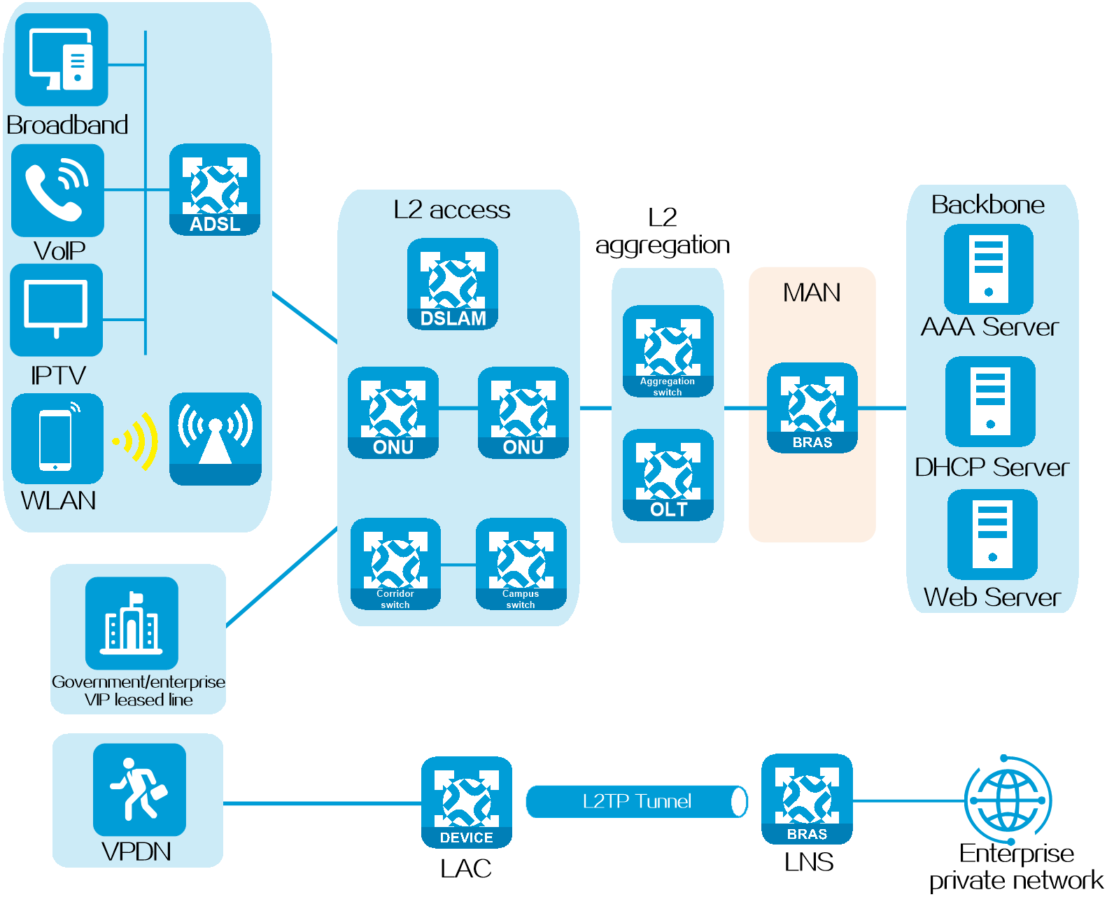
A broadband remote access server (BRAS) is an access gateway designed for broadband network applications. It bridges the broadband access network and backbone network, and provides basic access methods and the broadband access network management functions.
The network positioning of this product as a BRAS in the service provider applications is as shown in Figure 1.
Figure 1 Schematic diagram for the service provider BRAS network applications
|
|
NOTE: For more information about the service provider BRAS service applications in the CP and UP separation network, see H3C Telecom New MAN CUPS BRAS Service Deployment Guide. |
Hardware restrictions
Only some cards support PPPoE, L2TP, and IPoE. For more information, see the configuration guides for your device.
Introductions to key technologies
IPoE Web dual-stack authentication
Introduction
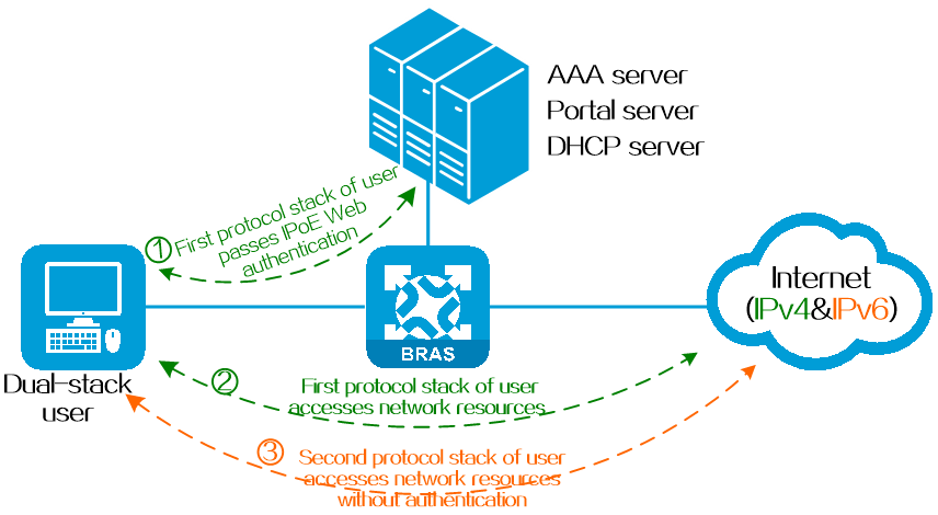
Dual-stack is one of the simplest and more user-friendly transition techniques among the many IPv4 to IPv6 transition technologies. In IPoE Web authentication, a dual-stack authentication means that when a dual-stack user is authenticated in one protocol stack (such as IPv4), the user is permitted to come online in the other protocol stack (such as IPv6) without authentication.
Based on the different ways in which users have their two protocol stacks come online, IPoE Web dual-stack authentication users are divided into three categories: dynamic dual-stack users, static dual-stack users, and mixed dual-stack users.
Figure 2 User authenticated in single stack and permitted in dual stack
Technical benefits
· For users, both protocol stacks come online through a single authentication process, improving the user experience.
· For servers, dual-stack authentication requires only one authentication process, reducing the load of AAA and portal servers.
· For administrators, treating the IPv4 and IPv6 protocol stacks of the same user as a single dual-stack user reduces the complexity of network management and maintenance.
Operating mechanism
The basic process of IPoE Web dual-stack authentication is as follows:
1. When a dual-stack user tries to come online in the first protocol stack (such as IPv4), the user enters the username and password on the authentication page. After successful authentication, the user can access the network resources of the protocol stack. The BRAS device records the user's MAC address, username, and authentication status.
2. When the user tries to come online in the second protocol stack (such as IPv6), the BRAS device checks whether the user has come online in the other protocol stack based on the user's MAC address. If it is online, the device permits the user in the second protocol stack without authentication.
Dual-stack authentication types
Dynamic dual-stack authentication
Application scenario
This type is mostly used in scenarios where the mobile terminals of users do not have a fixed IP address. For example, users access the network through mobile devices.
Operating mechanism
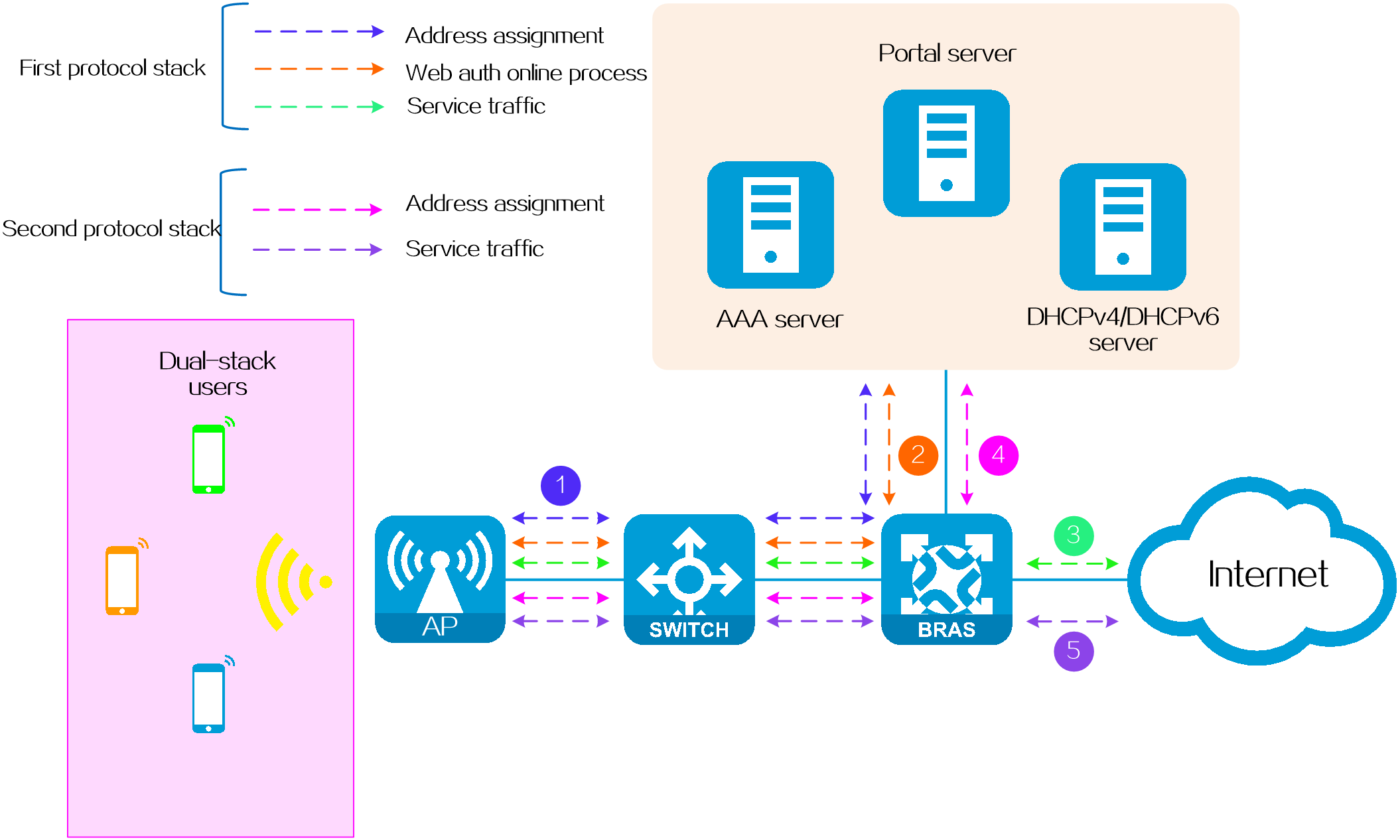
Both the IPv4 and IPv6 protocol stacks of this type of dual-stack user come online dynamically.
· In the IPv4 protocol stack: Users can trigger dynamic online authentication through DHCPv4 messages.
· In the IPv6 protocol stack: Users can trigger dynamic online authentication through DHCPv6 messages or ND RS messages.
Figure 3 Dynamic dual-stack authentication
|
|
NOTE: · IPoE Web dual-stack authentication enables users and the BRAS device to communicate across a Layer 3 network. When crossing a Layer 3 network, a user's MAC address cannot be directly passed to the BRAS device. In this case, the BRAS device retrieves the user's MAC address from the chaddr field of the DHCPv4 message or Option 79 of the DHCPv6 message. · The NDRS method supports only Layer 2 networking and does not support cross-subnet (Layer 3) networking. |
Static dual-stack authentication
Application scenario
It is often used in scenarios where the terminal IP address is fixed. For example, users access the operator through a fixed network port in their dormitory.
Operating mechanism
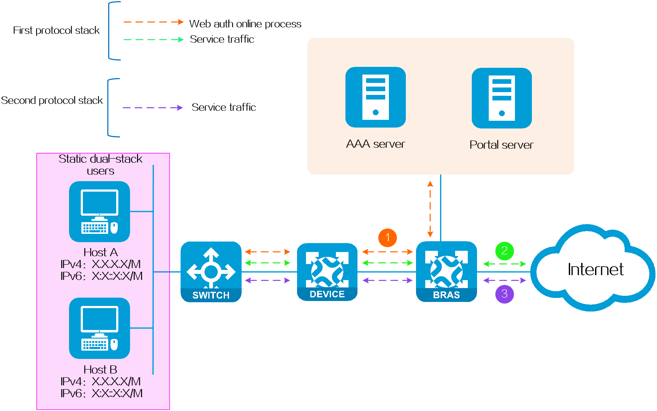
Both the IPv4 and IPv6 protocol stacks of this type of dual-stack user come online in the static method.
· In the IPv4 protocol stack: Users can trigger online authentication statically by sending IPv4 packets or ARP packets.
· In the IPv6 protocol stack: Users can trigger online authentication statically by sending IPv6 packets, NS packets or NA packets.
Figure 4 Static dual-stack authentication
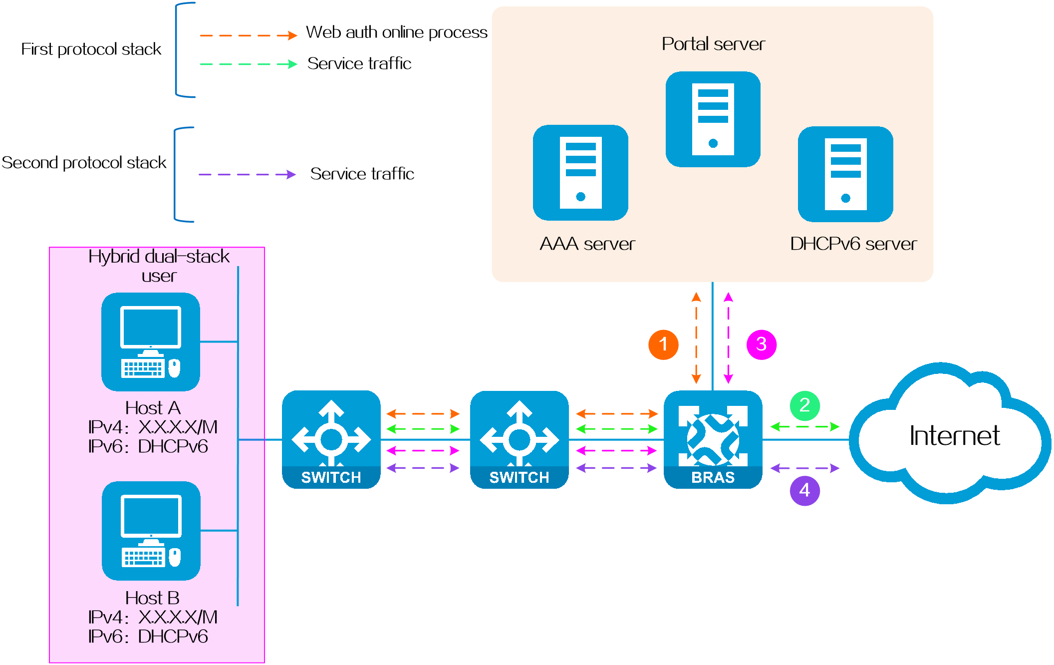
Hybrid dual-stack authentication
Application scenario
It is often used in scenarios where both fixed IP and non-fixed IP terminals exist in the network. For example, an IPv4 network uses fixed IPv4 addresses. With the rise of IPv6, users hope to upgrade the existing network so as to access IPv6 networks without changing the original IPv4 network deployment. At the same time, considering that IPv6 addresses are complex and inconvenient to remember, users hope to dynamically allocate IPv6 addresses through DHCPv6, that is, using a mixed address allocation method of static IPv4 + dynamic IPv6.
Operating mechanism
One protocol stack of this type of dual-stack user comes online using the static method, and the other protocol stack comes online using the dynamic method.
Figure 5 Hybrid dual-stack authentication
|
|
NOTE: · Only Layer 2 networking supports hybrid dual-stack authentication, while Layer 3 networking does not. · When a hybrid dual-stack user comes online, the stack in which the user comes online first is not determined. To ensure consistency in user attributes, you must configure the same usernames and authorization attributes for both stacks. |
Compositions of IPv4/IPv6 online authentication triggers
The IPv4 and IPv6 protocol stacks of IPoE Web authentication users support multiple online authentication triggers. The table below shows the details.
Table 1 Support for compositions of IPv4/IPv6 online authentication triggers
|
IPv6 IPv4 |
IPv6 interface static user |
IPv6 global static user |
DHCPv6 |
NDRS |
IPv6 packets with unknown sources |
|
IPv4 interface static user |
Supported |
Not supported |
Not supported |
Not supported |
Not supported |
|
IPv4 global static user |
Not supported |
Supported |
Supported |
Supported |
Not supported |
|
DHCPv4 |
Not supported |
Yes |
Supported |
Supported |
Not supported |
|
IPv4 packets with unknown sources |
Not supported |
Not supported |
Not supported |
Not supported |
Not supported |
|
|
NOTE: Interface static user refers to a static user configured on a specific interface. A static user configured on an interface takes effect only on that interface. Global static user refers to a static user configured in system view. A global static user takes effect globally. Using global static user configuration together with interface parameters can meet all the application requirements for interface-level static users. As a best practice, use global static users. |
URL allowlist for IPoE Web authentication
Introduction
With this feature configured, the unauthenticated or defaulting users can still access the network resource list. For example, on a network that uses IPoE Web authentication, you can add the payment page of the service provider to the URL allowlist.
· When a user does not pass IPoE Web authentication or has passed IPoE Web authentication but has owed fees, the user is still allowed to access the Internet.
· When a user owes fees, the user is still allowed to access the payment page of the service provider and pay the charge on the payment page pushed by the service provider. In this way, the user can quickly restore access to Internet.
Depending on the application scenarios, the URL allowlists for IPoE Web authentication include IP-based URL allowlists and domain name-based URL allowlists.
Technical benefits
· Ensure that users can access restricted networks while effectively controlling their access to the Internet.
· Support local online payment for users' Internet access needs, with easy operation.
· Allow the addition of new URL addresses based on existing allowlist configurations. Configurations (such as QoS) are reused, making it easy to expand the allowlist.
· Support URL allowlist entries based on domain names and IP addresses, which you can choose flexibly as needed.
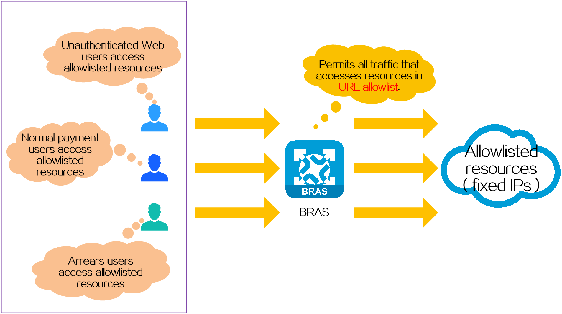
Operating mechanism
In IPoE Web authentication, the basic working process of URL allowlist is as follows:
1. QoS policies are deployed on the BRAS device to control access rights of normal payment and arrears users. The specific rules are as follows:
¡ Allow normal payment users' network traffic.
¡ Allow arrears users to access resources on the URL allowlist and the payment pages. The payment pages are pushed by the BRAS device when arrears users access resources not in the URL allowlist. Other access traffic of arrears users is discarded.
2. Before users pass Web authentication, they can only access the network resources specified in the URL allowlist.
3. After users pass Web authentication and come online, they can access network resources normally.
4. After the payment of a user is overdue, the AAA server issues a COA (Change of Authorization) message to the BRAS device, changing the authorization attribute of the user from normal payment user to arrears user. When arrears users access the Internet, the BRAS device pushes the payment page to require the users to pay.
5. After a user pays, the AAA server changes the user's Internet access rights from an arrears user to a normal payment user by COA, allowing the user to access network resources normally.
Figure 6 Schematic diagram

URL allowlist types
IP-based URL allowlist
Application scenarios
This type of URL allowlist specifies network resources with fixed IP addresses.
Operating mechanism
Configure IP-based URL allowlist entries on the BRAS device, for example, https://x.x.x.x.edu.cn.
Benefits
This type does not require deployment of a DNS server on the network. Therefore, the configuration is relatively simple.
Figure 7 IP-based URL allowlist
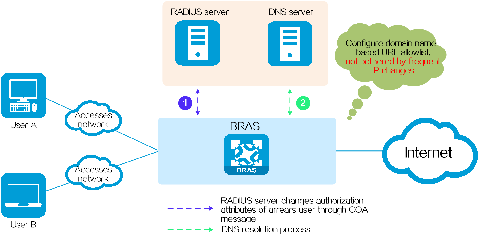
Domain name-based allowlist
Application scenarios
This type of URL allowlist specifies network resources whose IP addresses are not fixed. For example, when the payment of a user is overdue, the system needs to push a payment page to the user. For security purpose, the IP address of the payment page changes at intervals. To avoid frequent changes to the URL allowlist entry, you can add the domain name of the payment page to the URL allowlist.
Operating mechanism
On the BRAS device, configure a domain name-based URL allowlist entry (for example, https://abc.com/jiaofei), and then collaborate with a DNS server, which resolves the IP address dynamically.
Benefits
This method dynamically resolves IP addresses through DNS, which avoids frequent modifications to the URL allowlist configuration due to changes in IP addresses in the allowlist, making it easy to maintain.
Figure 8 Domain name-based allowlist
|
|
NOTE: |
IPoE Web authentication security protection
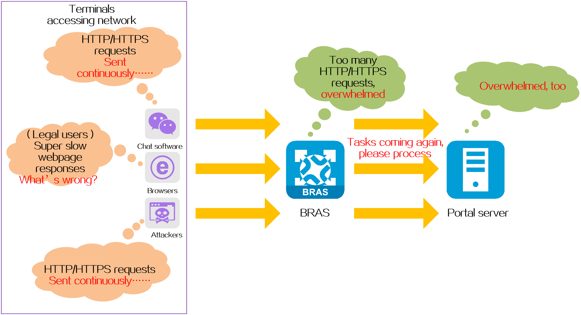
Introduction
In networks where IPoE Web authentication is used, the following types of HTTP/HTTPS attacks might occur:
· Certain non-browser applications, such as chat software, online disk, etc., continue to send a large number of HTTP and HTTPS request packets to a fixed IP address.
· Maliciously attack endpoints on the Internet, continuously sending a large number of HTTP and HTTPS request packets to different IP addresses randomly.
As the IPoE Web authentication process is triggered by HTTP/HTTPS messages, illegal HTTP/HTTPS messages will be regarded as normal IPoE Web authentication requests. This will occupy a large amount of system resources, causing the performance degradation of the BRAS device and delaying the processing of authentication requests from legitimate users. As the IPoE Web authentication requires the cooperation of the portal server, a large number of illegal authentication requests will also decrease the performance of the portal server.
IPoE Web authentication supports multiple security protection measures to resolve the attack issues: Web attack prevention, Web noise reduction, and specifying the URLs to trigger the push of the Web authentication page.
Figure 9 Schematic diagram
Technical benefits
· Provide network security protection and enhance network security.
· Support multiple security measures to provide network security protection from different dimensions.
Security protection measures
Web attack prevention
Protection targets
Protects the BRAS device and reduces the load on the portal server.
Protection mechanism
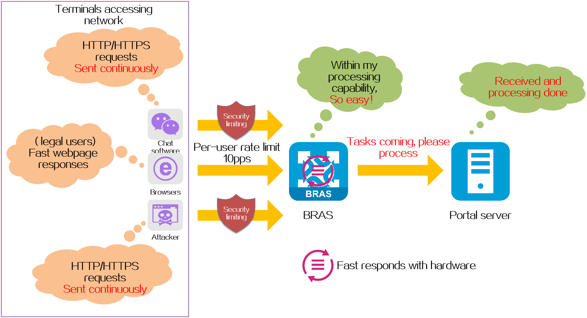
Uses the following anti-attack methods to intercept HTTP/HTTPS attack packets on the BRAS device.
· CAR for protocols of a single user—Limits the rate of all protocol packets sent by each user on the BRAS device, discards the packets that exceed the rate limit, and thus controls the overall receiving rate of protocol packets within the range that the BRAS device can bear.
· Fast responses to HTTP packets—The BRAS device identifies HTTP requests through hardware and automatically responds the requests, reducing the burden on the CPU and avoiding being a target of denial of service attacks.
· Destination IP-based HTTP/HTTPS attack defense—The BRAS device will monitor and collect statistics of HTTP/HTTPS packets sent by unauthenticated users to any destination IP address. If the total number of HTTP/HTTPS packets sent to a destination IP address within a statistics collection interval exceeds the specified threshold, the device determines an attack has occurred. Then, the device blocks attack packets or outputs attack logs as configured.
Figure 10 Web attack prevention
Web noise reduction
Protection targets
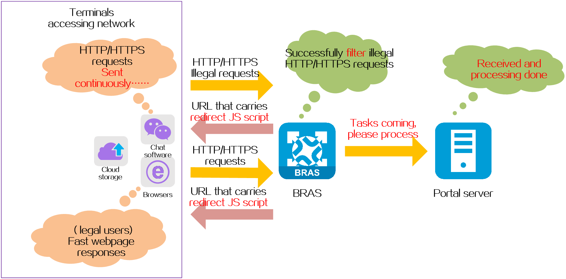
Protects the portal server from HTTP/HTTPS redirects initiated by non-browsers such as chat software and cloud storage.
Protection mechanism
The BRAS device uses its built-in redirect JS script to implement Web noise reduction.
Web noise reduction works as follows:
1. When the BRAS device receives an HTTP/HTTPS request packet from a terminal, it sends a URL redirect packet carrying the redirect JS script. These redirect URLs can only be recognized by standard browsers.
2. Terminals using standard browsers receive the redirect packet from the BRAS device, analyze the URL, and send a web authentication request to the specified portal server. Other terminals such as chat software and cloud storage are unable to recognize the redirect URLs and do not initiate Web authentication requests to the portal server.
Figure 11 Web noise reduction
Specify the URL that can trigger pushing of the Web authentication page
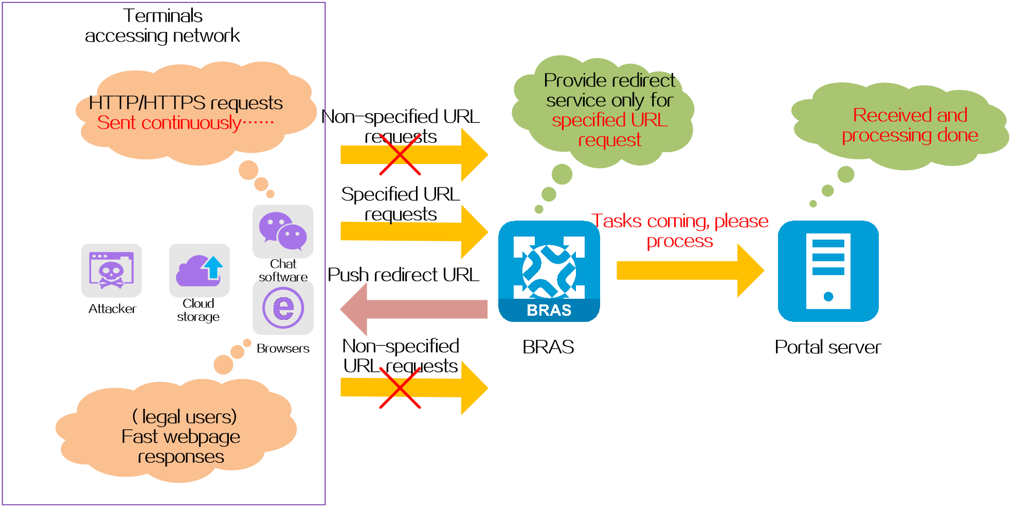
Protection targets
Protects the BRAS device and reduces the load on the portal server.
Protection mechanism
Normally, when the BRAS device receives an HTTP/HTTPS request sent from a terminal to any destination IP address, it pushes a redirect Web authentication page to the terminal. In networks that require high security, you can specify the URL that can trigger pushing of a Web authentication page on the BRAS device. After deploying this function, the BRAS device will only push a Web authentication page for terminals accessing the specified URL, and directly discard HTTP/HTTPS requests accessing other URLs.
Figure 12 Specify the URL that can trigger pushing of the Web authentication page
Comparison of security protection measures
Table 2 Comparison of security protection measures
|
Attack prevention methods |
Protection targets |
Redirect for any URL request |
Redirect for fixed URL requests |
Fixed dest IPs attack prevention |
Random dest IPs attack prevention |
|
Web attack prevention |
BRAS device Portal server |
Supported |
Not supported |
Supported |
Supported |
|
Web noise reduction |
Portal server |
Supported |
Not supported |
Not supported |
Not supported |
|
Specify the URL that can trigger pushing of the Web authentication page |
BRAS device Portal server |
Not supported |
Supported |
Supported |
Supported |
PPPoE
Introduction
Now, the service providers pose much higher requirements on the broadband access technologies. Traditional broadband access technologies (for example, xDSL, CableModem, and Ethernet) gradually cannot meet such requirements in user management and accounting.
Among numerous access technologies, Ethernet access is economical, and PPP can provide good access control and accounting functions. Combining the economy of Ethernet and the good scalability and management & control functions of PPP, Point-to-Point Protocol over Ethernet (PPPoE) was introduced.
Because PPPoE well solves the practical application problems such as user management and network access accounting, PPPoE is widely recognized and used by service providers.
Technical benefits
Benefits for users
For users, PPPoE delivers the following benefits:
· Uses the traditional dialup Internet access method, and allows users to continue to use familiar hardware and similar software for Internet access.
· Compatible with all existing xDSL modems, and does not require complex configuration of the clients' xDSL modems.
· Uses Ethernet cards to connect PCs and xDSL modems, and allows multiple PCs to share one xDSL line simultaneously, which can save the users' investment.
Benefits for service providers
For service providers, PPPoE delivers the following benefits:
· Allows service providers to provide broadband access services that support multiple users through technologies like Digital Subscriber Line (DSL), cable modems, or wireless connections.
· Allows service providers to use reliable and familiar technologies to accelerate the deployment of high-speed Internet services, with little impact on existing network deployment.
· Allows service providers to use access control functions to confirm the identity of users, use billing functions to charge users, and monitor user network behaviors to ensure network security.
· Allows endpoint users to simultaneously access multiple service providers and dynamically select services, and makes it easy for service providers to create and offer new services.
Network structure
PPPoE uses the client/server model. The PPPoE client initiates a connection request to the PPPoE server. After session negotiation between them is complete, a session is established between them, and the PPPoE server provides access control, authentication, and accounting to the PPPoE client.
PPPoE network structures are classified into router-initiated and host-initiated network structures depending on the starting point of the PPPoE session.
Router-initiated network structure
As shown in Figure 13, the PPPoE session is established between routers (Router A and Router B). All hosts share one PPPoE session for data transmission without being installed with PPPoE client software. This network structure is typically used by enterprises.
Figure 13 Router-initiated network structure
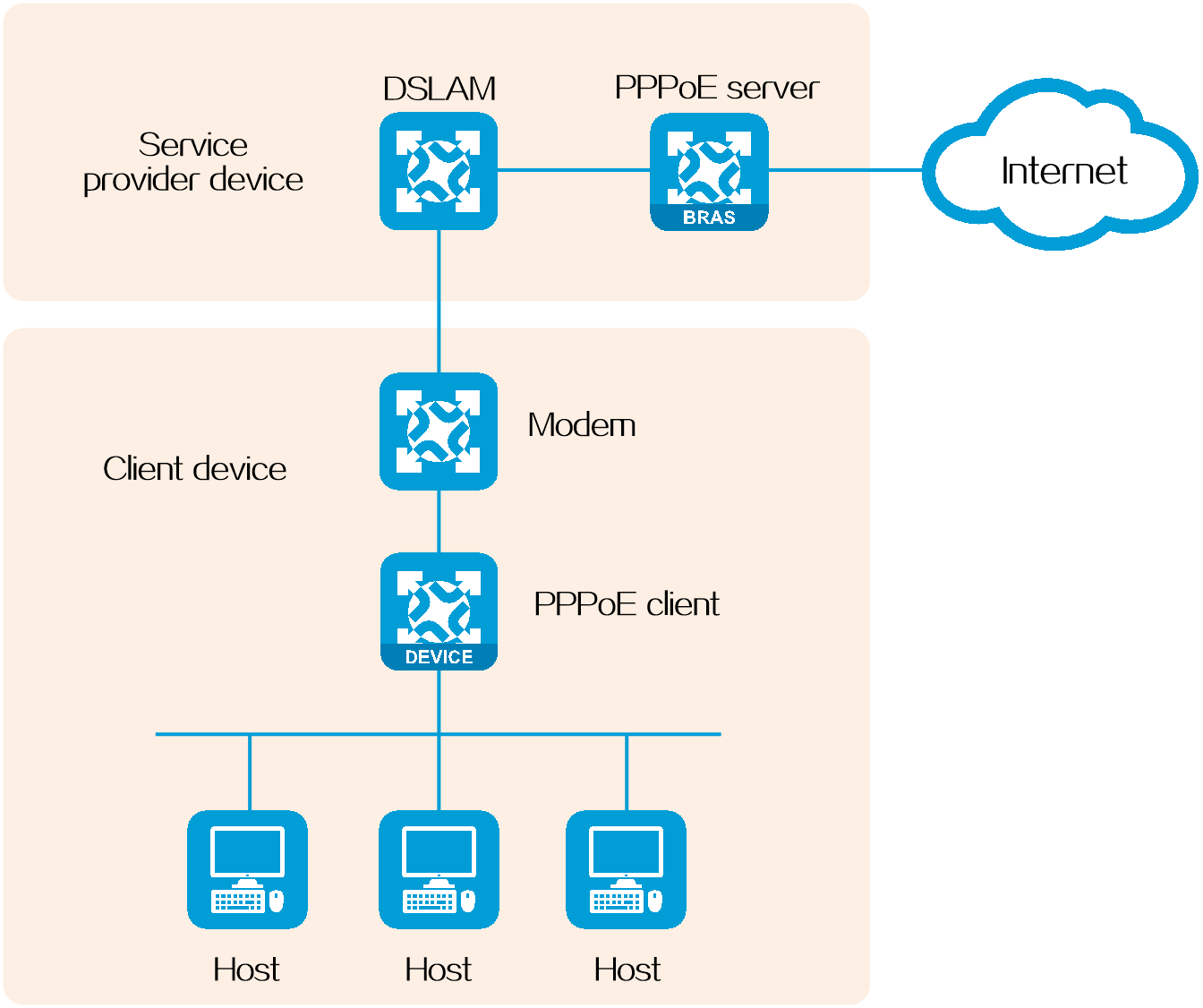
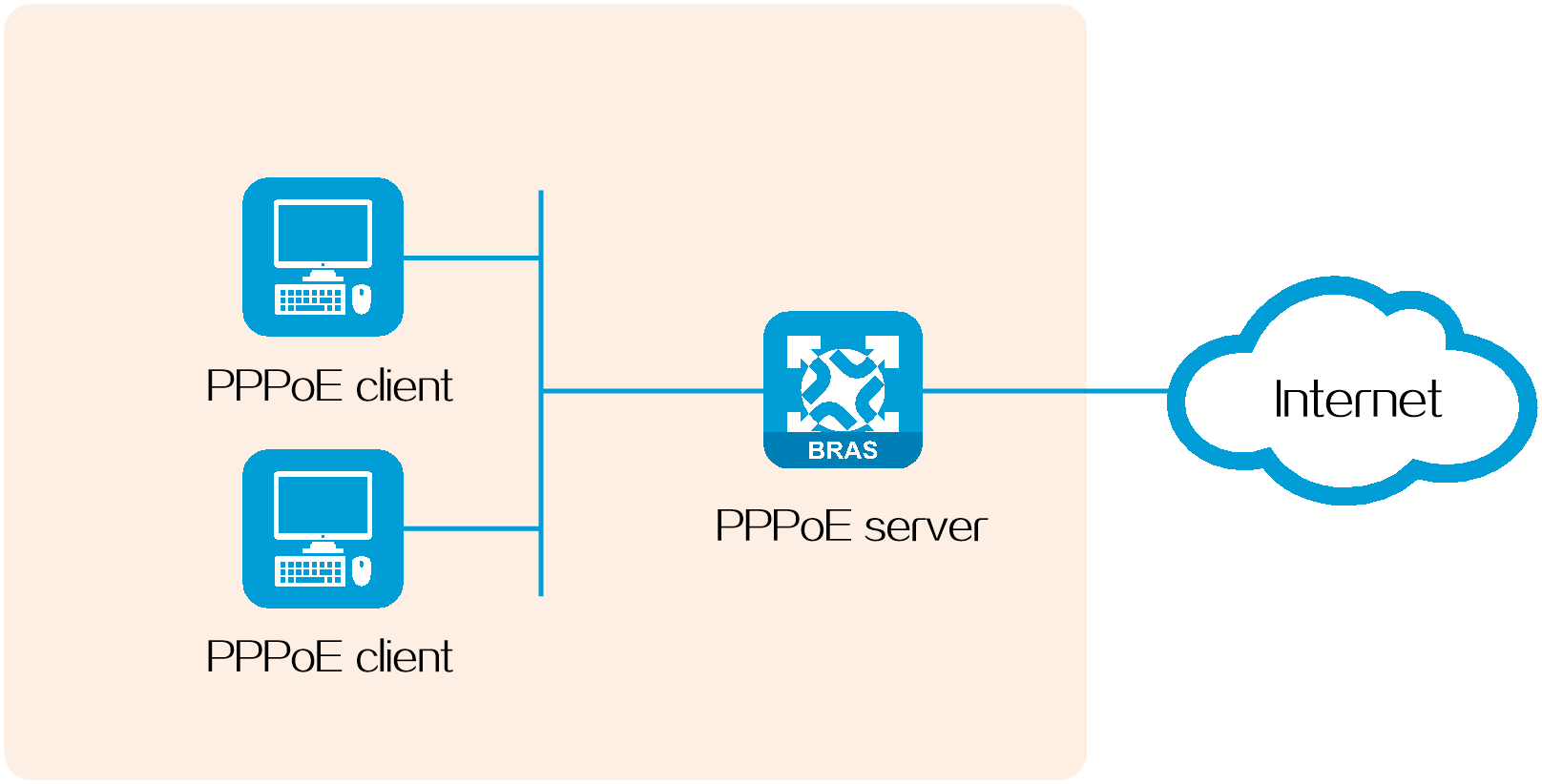
Host-initiated network structure
As shown in Figure 14, a PPPoE session is established between each host (PPPoE client) and the service provider router (PPPoE server). The service provider assigns an account to each host for billing and control. The host must be installed with PPPoE client software.
Figure 14 Host-initiated network structure
L2TP
Introduction
Layer 2 Tunneling Protocol (L2TP) is a Layer 2 tunneling protocol. L2TP sets up point-to-point L2TP tunnels on a public network (for example, the Internet). With L2TP, remote users (for example, users in branches and staff on business trips of an enterprise) can connect to the private network of the enterprise through L2TP tunnels to access private network resources after connecting to a public network.
Depending on the application scenarios, L2TP tunneling modes include NAS-initiated, client-initiated, and LAC-auto-initiated.
Figure 15 Schematic diagram
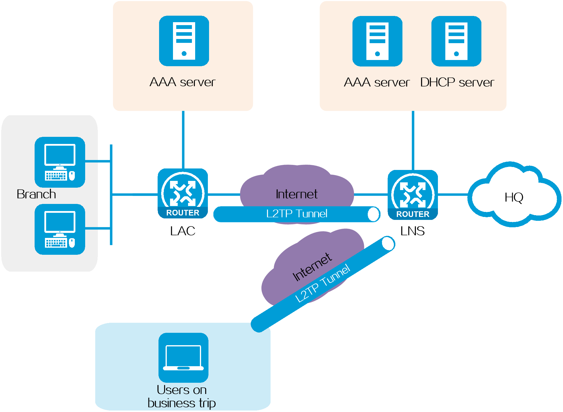
A typical L2TP network has the following components:
· Remote user—A remote user refers to a user on a business trip or a branch that needs to access the private network of the enterprise HQ. A remote user is usually a dialup user's host or a branch's network device that needs to access the private network.
· LAC—An L2TP access concentrator (LAC) is both PPP and L2TP capable. It is usually a network access server (NAS) located at a local ISP or a border gateway in a branch.
· LNS—An L2TP network server (LNS) is both PPP and L2TP capable. It is usually an edge device on an enterprise HQ network.
NAS-initiated mode
Application scenarios
This mode is applicable in the scenario where internal communication between the branches and HQ of an enterprise is required and the HQ wants to perform granular, differentiated management for the access permissions of each dialup user.
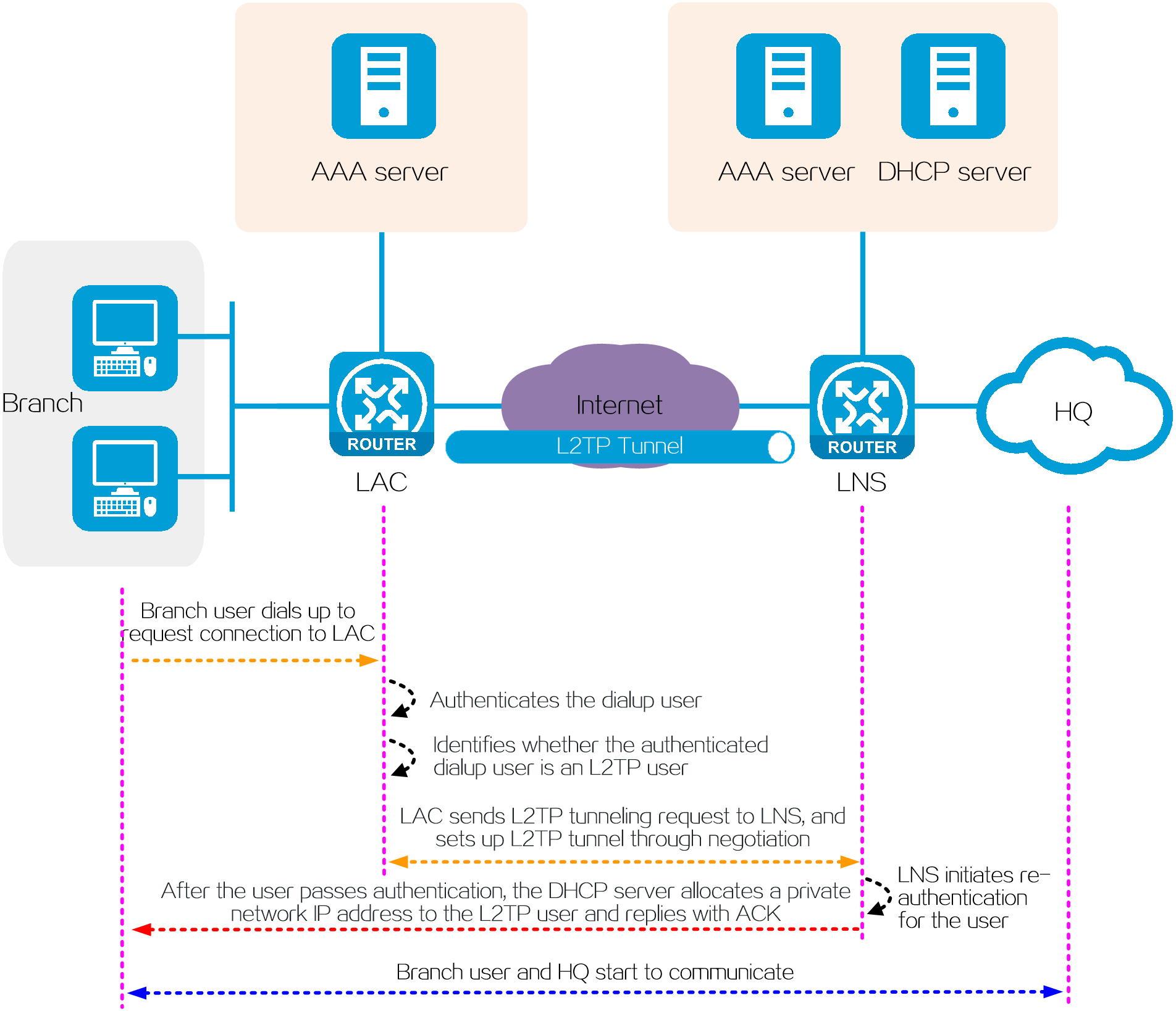
Operating mechanism
In NAS-initiated mode, a branch and the HQ communicate in the following process:
1. A dialup user in a branch requests to connect to the LAC.
2. The AAA server on the LAC side authenticates the dialup user.
3. After the user passes authentication, the LAC identifies whether the dialup user is an L2TP user according to the username and ISP domain of the dialup user.
4. If the user is an L2TP user, the LAC sends an L2TP tunneling request to the LNS of the user's enterprise. After an L2TP tunnel is established, the LAC transparently sends authentication information to the LNS through the tunnel. If the user is not an L2TP user, the user is processed as a non-L2TP user. The detailed process is not shown in this document.
5. To enhance the network security, the LNS will send a re-authentication request for the L2TP user to the LNS-side AAA server after receiving authentication information from the L2TP user.
6. After the user passes authentication, the DHCP server allocates a private network IP address to the L2TP user.
7. The branch user starts to communicate with the HQ through the L2TP tunnel.
Figure 16 Network diagram
Benefits
· To access the HQ network, each dialup user in a branch must separately dial up and perform authentication, and can access the HQ network only after passing authentication. The HQ can perform granular, differentiated management for users according to the access permissions of each dialup user.
· This mode authenticates a dialup user on both the LAC side and LNS side to enhance the network security.
LAC-auto-initiated mode
Application scenarios
This mode is applicable to the scenario where internal communication between the branches and HQ of an enterprise is required and the HQ wants to simplify O&M for users. In this scenario, each LAC is considered as a dialup user, and users in the branches attached to the LAC are not concerned.
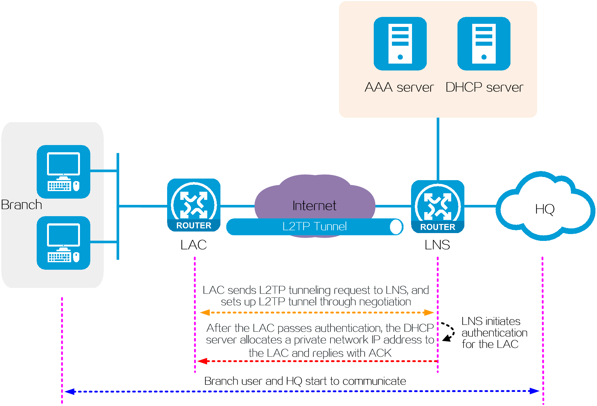
Operating mechanism
In LAC-auto-initiated mode, a branch and the HQ communicate in the following process:
1. The LAC acts as a dialup user to directly initiate a tunneling request to the LNS. An L2TP tunnel is established between the LAC and LNS through negotiation.
2. The LNS initiates an authentication request for the LAC to the LNS-side AAA server.
3. After the LAC passes authentication, the DHCP server allocates a private network IP address to the LAC.
NOTE: The private network IP address is allocated to the LAC rather than branch users.
4. The branch users use the LAC as the enterprise private network gateway, and start to communicate with the HQ through the gateway.
Figure 17 Network diagram
Benefits
· An L2TP tunnel is not triggered by dialup of a branch user. Instead, the LAC directly initiates an L2TP tunneling request to the LNS, and then an L2TP tunnel is establish through negotiation.
· The HQ considers each LAC as a dialup user, and does not concern users in the branches attached to the LAC. Therefore, the user O&M is simple.
· The connection between a branch user and the LAC is not confined to a dialup connection and can be any IP-based connection. The requirements for user endpoints are low.
NAS-initiated mode vs LAC-auto-initiated mode
Both the NAS-initiated mode and LAC-auto-initiated mode apply to the scenario where communication between the branches and HQ of an enterprise is required. The following table shows the comparison between the two modes. Select a mode as needed.
Table 3 NAS-initiated mode vs LAC-auto-initiated mode
|
Operating mode |
NAS-initiated mode |
LAC-auto-initiated mode |
|
Application scenarios |
Communication between branches and HQ of an enterprise |
Communication between branches and HQ of an enterprise |
|
L2TP tunnel establishment triggering mode |
Triggered by branch user dialup |
Triggered by LAC automatically |
|
Branch user authentication requirements |
Each branch user must separately dial up and perform authentication |
A branch user does not need to separately dial up or perform authentication. The LAC acts as a dialup user and performs unified authentication |
|
Whether AAA server is required on LAC |
Yes |
No |
|
AAA authentication on LAC/LNS |
Authenticates a dialup user on both the LAC side and LNS side. Two authentications are performed for a user |
Authenticates a dialup user only on the LNS side for one time |
|
Security |
High |
Relatively high |
|
Link requirements between branch and LAC |
PPP dialup link |
Any IP-based link |
Client-initiated mode
Application scenarios
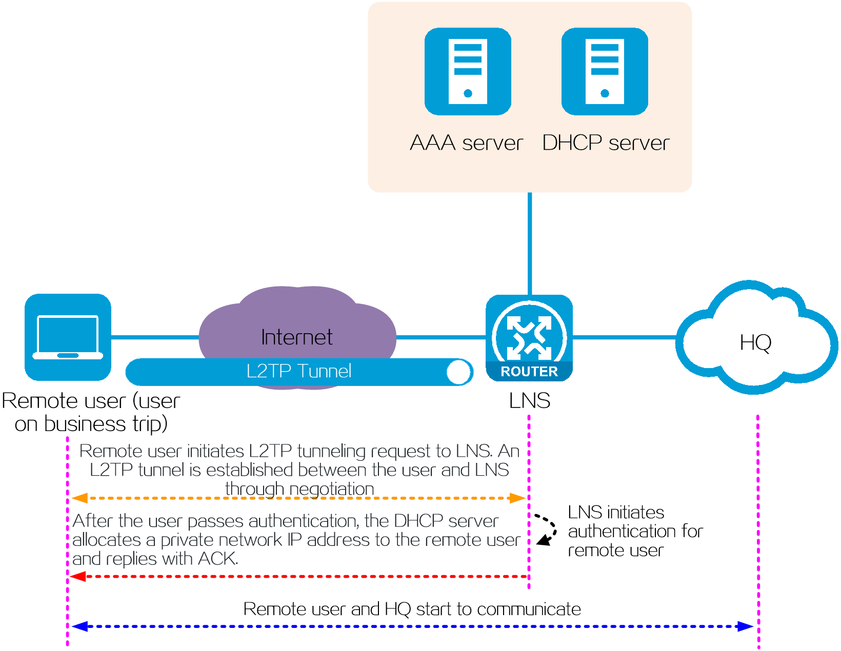
This mode is applicable to the scenario where the mobile office users (for example, users on business trips) need to communicate with the private network of the enterprise HQ.
Operating mechanism
In client-initiated mode, a remote user and the HQ communicate in the following process:
1. After a remote user connects to the public network, the user initiates an L2TP tunneling request to the LNS. An L2TP tunnel is established between the LAC and LNS through negotiation.
2. The LNS initiates an authentication request for the remote user to the LNS-side AAA server.
3. After the user passes authentication, the DHCP server allocates a private network IP address to the remote user.
4. The remote user starts to communicate with the HQ through the L2TP tunnel.
Figure 18 Network diagram
Benefits
· When an enterprise user works in a mobile office environment (for example, home, hotel, or outdoors) accesses the Internet, the user can establish an L2TP tunnel between the public network and the enterprise HQ network. In this way, the user can securely access the private network resources of the enterprise. The whole access process is simple and secure.
· To access the HQ network, each remote user must separately dial up and perform authentication and can access the HQ network only after passing authentication. The HQ can perform granular, differentiated management for remote users according to the access permissions of each remote user.
Intelligent speed increase (ITA)
Introduction
Intelligent speed increase, as the name suggests, refers to dynamically increasing the user's network access speed to meet diverse user bandwidth requirements. A variety of business requirements for intelligent speed increase can be met by using ITA technology on the BRAS device provided by service providers for broadband access.
Intelligent Target Accounting (ITA) provides a flexible accounting solution based on the destination addresses of users' traffic.
Technical benefits
· Improves the user's Internet access experience.
By using bandwidth according to demand and letting users pay for the experience, we ensure the ultimate Internet access experience for the user. For example, when a user is watching a high-definition video, the basic bandwidth can be temporarily increased to the required bandwidth level (such as 30 Mbps to 80 Mbps ) to ensure an optimal viewing experience. After the program is over, the user's available bandwidth can automatically fall back to the basic bandwidth.
· Achieves differentiating operation and service for network bandwidth resources
By differentiating various service types according to the destination address, ITA can implement differentiated speed limiting, scheduling, and billing for different types of services. There is a large difference in the rates of Internet traffic and internal traffic. ITA can distinguish and charge the two types of traffic according to different rate levels, ensuring the operating income of the local operator.
· Expands the operator's commercial value in the industry chain.
Without changing the current network structure, ITA can help operators meet users' differentiated bandwidth and content requirements, stimulating greater broadband consumption potential. At the same time, after the user uses the broadband speed-up function, the user can obtain short-term value-added services through monthly billing and per-use billing. After long-term use, the user is likely to become a high-bandwidth user of the operator.
Operating mechanisms
Fundamentals
ITA provides a flexible accounting solution for users that request services of different charge rates. By defining different traffic levels based on the destination addresses of users' traffic, you can use ITA to separate the traffic accounting statistics of different levels for each user.
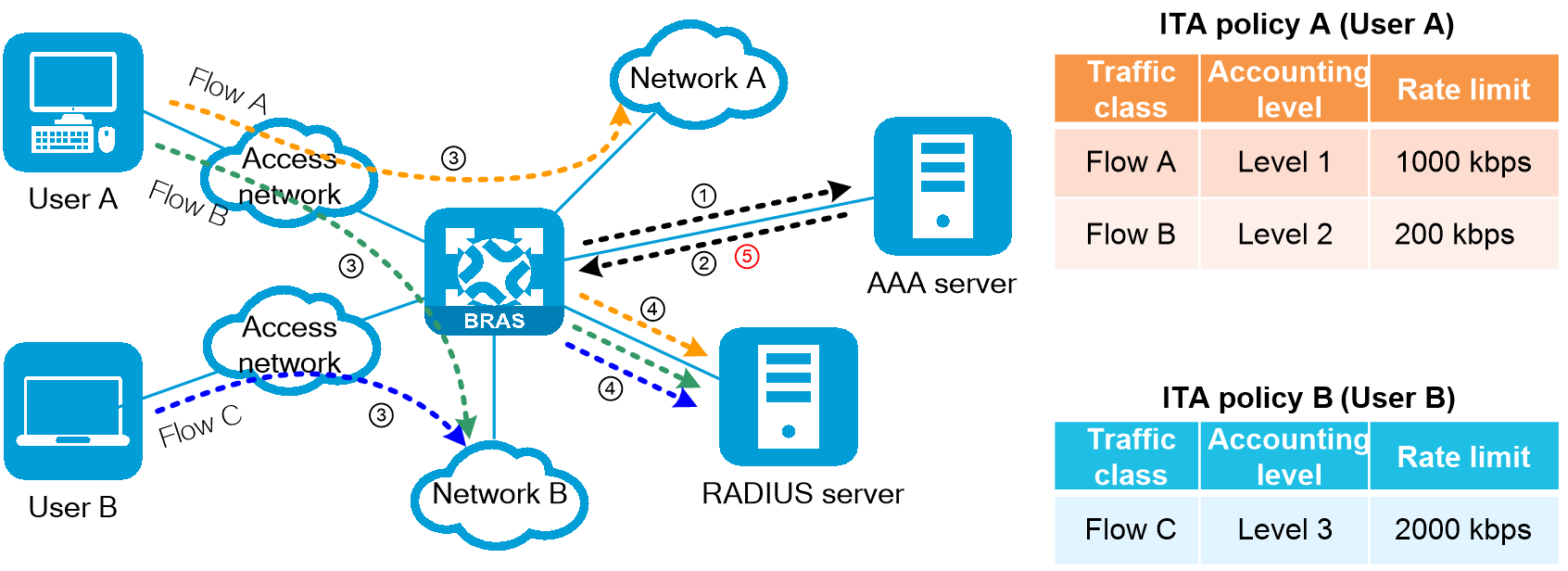
Service processing flow
The ITA service processing flow is as follows:
1. The user initiates an online request to the BRAS device, and the BRAS device sends an authentication request message to the AAA server.
2. The AAA server responds to the BRAS device with an authentication success message and issues an ITA policy for the user. The ITA policy specifies the rate level that needs to be independently billed, rate limit parameters, and the independent billing plan used. The number of traffic billing levels configured for users of different access methods is different. Refer to the configuration guide for the corresponding product.
3. When the user accesses the network after authentication, the BRAS device identifies the flow that needs to be independently billed and marked with the corresponding billing level based on the user profile authorized for the user or the QoS policy applied.
4. For ITA traffic, the BRAS device sends billing requests to the RADIUS accounting server in the ITA policy and performs separate billing.
The operator can use the AAA server to issue CoA messages to modify the user's ITA policies online.
Figure 19 Service processing flow
CGN
Introduction
Carrier Grade NAT (CGN), also known as large-scale NAT (LSN), improves public IPv4 address usage for address translation and can be a long-term solution for IPv4 address depletion.
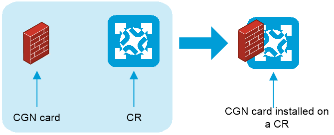
The CGN-capable cards are called CGN cards. They can be installed on the core routers (CRs) or broadband remote access server (BRAS) devices.
CGN card installed on a CR
As shown in Figure 20, the CGN card is installed on a CR. Integrated with the CGN and routing features, the CR provides services for MAN users.
Figure 20 CGN card installed on a CR
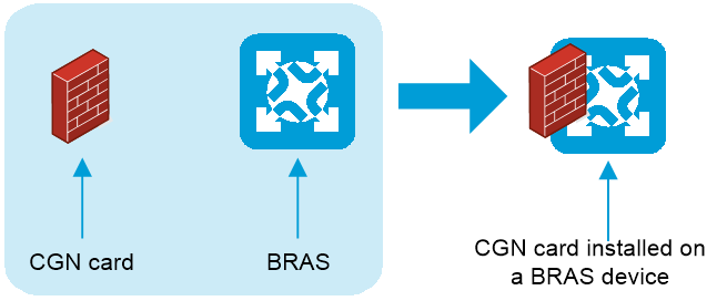
CGN card installed on a BRAS device
As shown in Figure 21, the CGN card is installed on a BRAS device. Integrated with the access and CGN features, the BRAS device provides services for access users.
Figure 21 CGN card installed on a BRAS device
Technical benefits
Traditionally NAT is deployed on the customer premises equipment (CPE) for address translation of few users. Deployed on an ISP networks, CGN translates addresses for a large number of users and supports more concurrent users, higher performance, and better user tracing.
Compared with traditional NAT, CGN provides the following benefits:
· Large capacity—Deployed on an ISP network, CGN can translate addresses for a large number of users.
· High availability—To avoid network service interruption caused by the failure of a single CGN card, you can use multiple CGN cards to configure intra-device CGN backup or centralized backup for distributed CGN.
· Traceability—CGN supports user logs and flow logs. The administrator can trace users by obtaining the IP addresses of private users in the logs based on the public addresses and port numbers in service packets.
· CGN resource management—CGN resources contain public addresses and port blocks. You can limit the number of ports and the number of private users sharing the same public IP address to prevent individual users from consuming too many CGN resources.
CGN deployment
CGN deployment falls into the following types based on the CGN card location:
· Centralized CGN deployment.
· Distributed CGN deployment.
Centralized CGN deployment
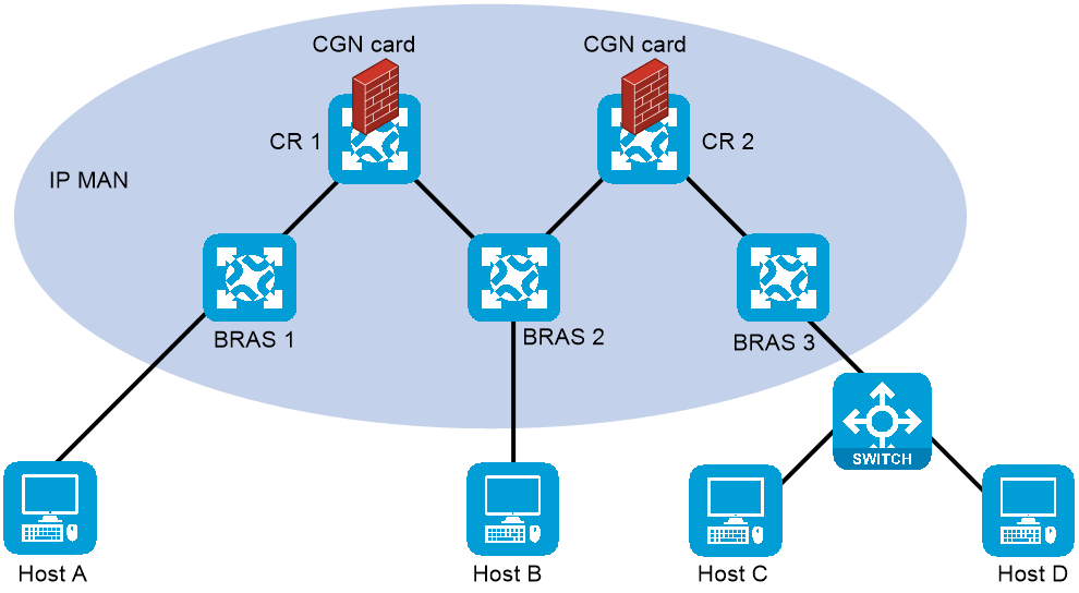
A CGN-capable device is close to or at the core of MAN, typically deployed on a CR. To implement the deployment, you can connect devices with CGN cards installed to the CRs (Figure 22) or install CGN cards on the CRs (Figure 23).
Centralized CGN deployment has the following features:
· Applicable to networks with a small number of users and low volumes of traffic.
· Broad impact range when a device is faulty.
· Requires a small number of CGN cards.
Figure 22 Connecting CRs to devices with CGN cards installed
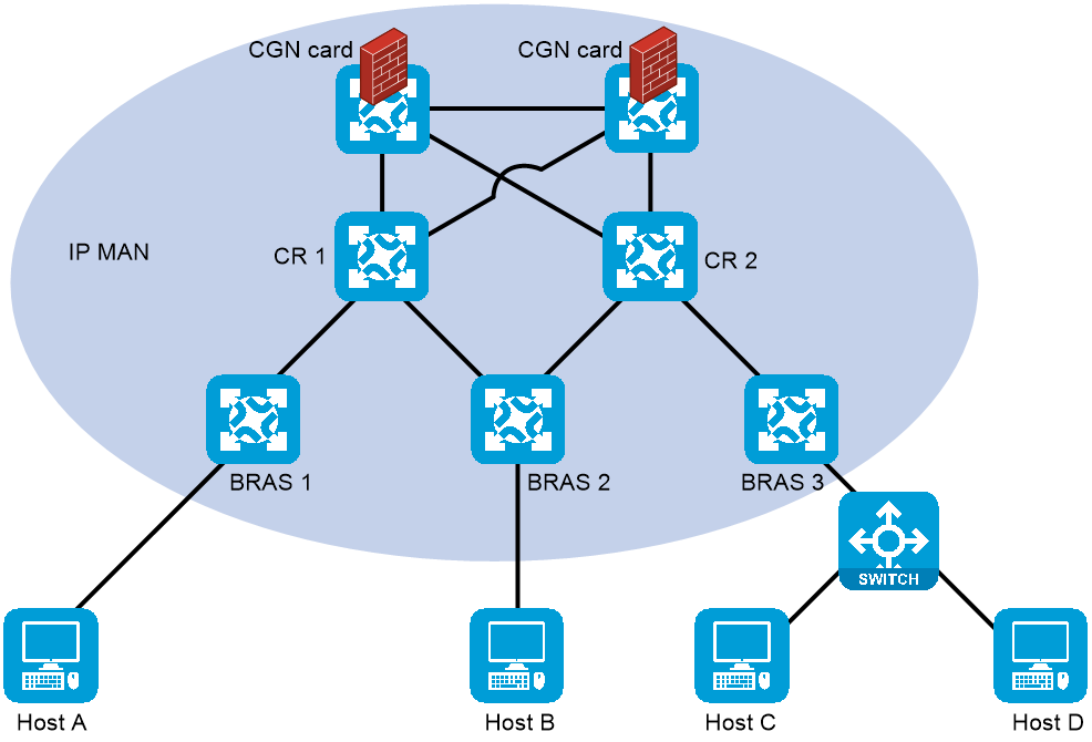
Figure 23 Installing CGN cards on the CRs
Distributed CGN deployment
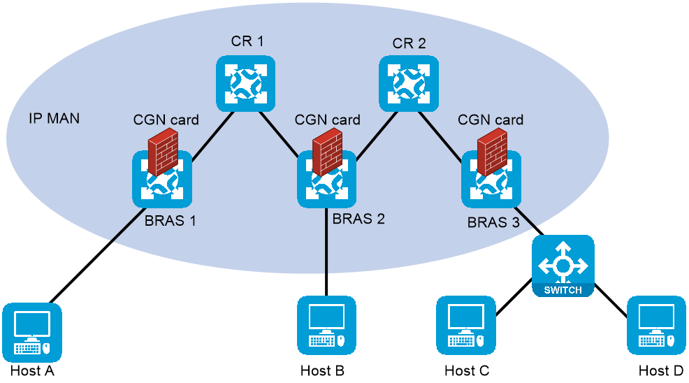
A CGN-capable device is close to or at the edge of MAN, typically deployed on a BRAS device. As shown in Figure 24, to implement distributed CGN deployment, a CGN card is installed on each BRAS device.
Distributed CGN deployment has the following features:
· Applicable to networks with excessive users and high volumes of traffic.
· Small impact range when a device is faulty.
· Requires a large number of CGN cards.
Figure 24 Distributed CGN deployment
CGN backup
A CGN card is the core component on an ISP network, which translates addresses for a large number of users. If the CGN card has failed, network services will become unavailable for the users. To enhance CGN availability, use multiple CGN cards to avoid network service interruption caused by the failure of a single CGN card.
The following CGN backup methods are available:
· Centralized backup for distributed CGN.
· Intra-device CGN backup.
Centralized backup for distributed CGN
The network contains both distributed CGN devices and centralized CGN devices. Typically, distributed CGN devices process NAT services in centralized backup for distributed CGN. When the CGN card on a distributed device fails, traffic is switched to the centralized CGN device for address translation. After the faulty CGN card recovers, traffic is switched back to the distributed device.
As shown in Figure 25, traffic is NATed by the CGN card on the BRAS device. When the CGN card on the BRAS device fails, traffic is switched to the CGN card on the CR for address translation, as shown in Figure 26.
Figure 25 Centralized backup for distributed CGN (when the CGN card on the BRAS device works correctly)

Figure 26 Centralized backup for distributed CGN (when the CGN card on the BRAS device fails)

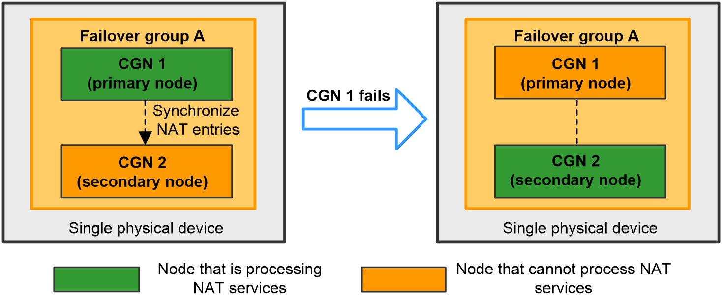
Intra-device CGN backup
The two CGN cards installed on the same device back up NAT services for each other.
After the two CGN cards are assigned to the same failover group, the failover group determines the active state of the primary and secondary nodes (CGN cards). Only the node in active state can process NAT services.
As shown in Figure 27, intra-device CGN backup works as follows:
· When the primary node works correctly, it is in active state and processes NAT services. The primary node also synchronizes NAT entries to the secondary node.
· When the primary node fails, the secondary node becomes in active state and takes over the NAT services.
Figure 27 Intra-device CGN backup
Application scenarios
Centralized backup for distributed CGN
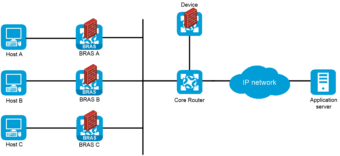
As shown in Figure 28, BRAS A, BRAS B, BRAS C, and Device reside in the same AS and run IS-IS to implement Layer 3 connectivity. BRAS A, BRAS B, and BRAS C provide access services for the hosts and NAT services through CGN cards. When the CGN card on BRAS A, BRAS B, or BRAS C fails, traffic is switched to the CGN card on Device that is connected to the core router.
Intra-device CGN backup
As shown in Figure 29, the BRAS device provides access services for the host and NAT services through CGN 1 and CGN 2, and supports intra-device CGN hot backup. The primary/secondary switchover of the CGN cards does not affect user services, which enhances CGN availability.

Multicast access control
About multicast access control
Multicast access control provides a mechanism to control a user's access to multicast data by limiting the multicast groups that the user can join. When a user logs in, the BRAS downloads the access authorization profile of the user. Based on the authorization profile, the BRAS accepts or denies the reports from the user to join multicast groups.
Benefits
Multicast access control can be applied to different types of access network environments, and supports multicast group access control for users with various access methods such as IPoE, PPPoE, and IPoE web. By effectively controlling illegal or unauthorized multicast users, this feature enables flexible operations and management of multicast services and ensures reasonable revenue of service providers.
Typical network models
For IPTV services of service providers, you can configure multicast access control on the BRAS to control the video on demand (VOD) privilege of IPTV users. The service providers set different charging plans for different VOD channels, and users obtain privileges by paying, ensuring service providers’ revenue.
As shown in the following figure, IPTV users within a VLAN access the service provider network through IPoE. The Layer 2 network devices that users connect to support IGMP snooping, and the BRAS uses VLAN-based static replication to replicate multicast packets.
Figure 30 Typical network models
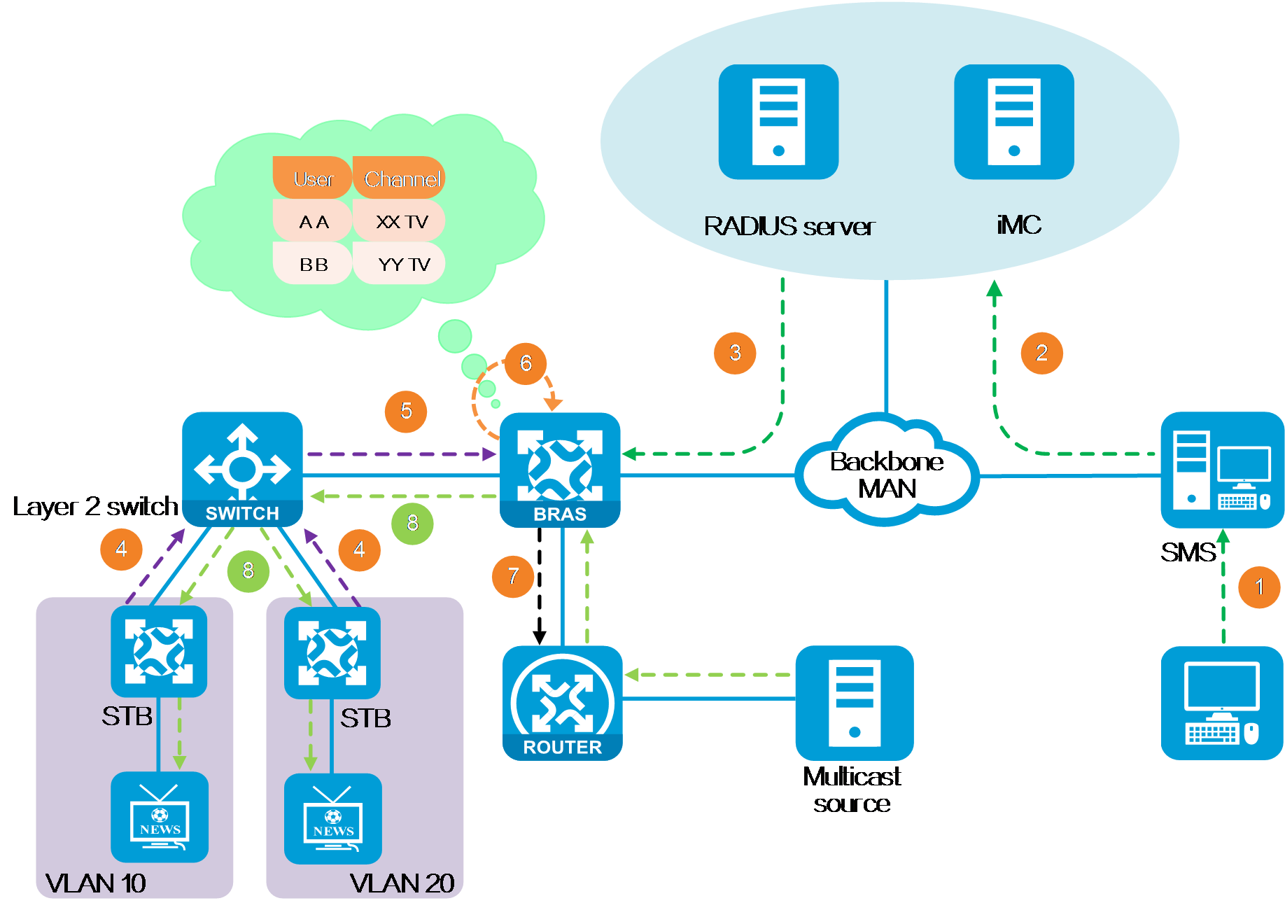
IPTV service activation is as follows:
1. Users go to a business hall or apply for activation and channel subscription through a web self-service system. The subscribe management system (SMS) records user information.
2. SMS informs iMC of the user information.
3. iMC sends the user's multicast group authorization information to the BRAS through the RADIUS server.
4. The set-top box (STB) is turned on and the user is authenticated. After the user requests to play a channel, the STB sends an IGMP join request.
5. The Layer 2 device forwards the received IGMP membership report message to the BRAS, and records the multicast group requested by the user to forward the multicast data to the corresponding user.
6. After the BRAS receives the IGMP membership report message, it determines whether the user has permission to join the multicast group based on the user's authorization information. If the user is not authorized, the BRAS discards the IGMP membership report message.
7. If the user is authorized, the BRAS obtains the receiver information of the multicast group, and uses a multicast routing protocol to build the shortest path for multicast data forwarding. The multicast packets sent by the corresponding multicast source arrive at the BRAS through the multicast forwarding tree.
8. The BRAS encapsulates the VLAN tag for the multicast packets of the designated channel requested by the user, and sends them to the downstream Layer 2 device, which sends them to users in the designated VLAN.
Working mechanism
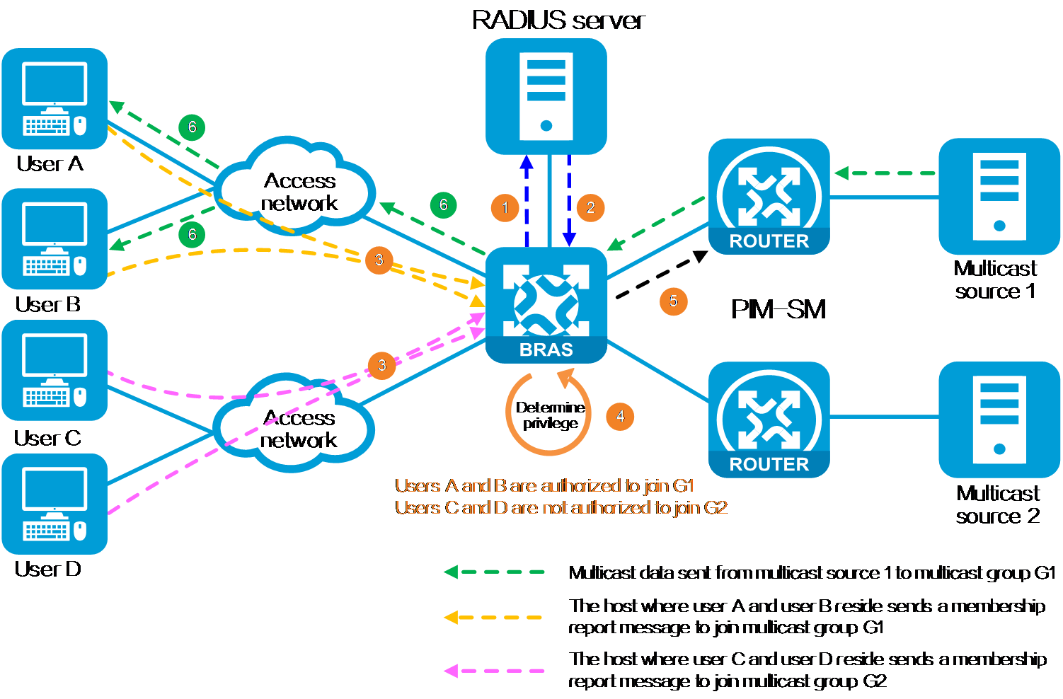
Multicast access control operates as follows:
1. After the user sends a request to connect to the device, the BRAS sends an authentication request to the RADIUS server.
2. The RADIUS server responds with an authentication success message and sends the user's multicast group authorization information to the BRAS.
3. After coming online, the user sends an IGMP membership report packet to the BRAS, requesting to join the corresponding multicast group. A multicast group is a set of receivers identified by an IP multicast address.
4. After the BRAS receives the IGMP membership report message, it determines whether the user has to join the multicast group based on the user's multicast group authorization information. If the user is not authorized, the BRAS discards the IGMP membership report message.
5. If the user is authorized, the BRAS obtains the receiver information of the multicast group, and uses a multicast routing protocol, for example, PIM-SM to build the shortest path for multicast data forwarding.
6. When the BRAS receives a multicast packet from the source, it distributes the multicast packet to the corresponding users based on the multicast replication method configured on the device.
Figure 31 Working mechanism
Multicast packet replication methods
As shown in the Table 4, in different application scenarios, the BRAS distributes received multicast packets to authorized access users based on the configured multicast replication method.
Table 4 Replication policy selection
|
Replication method |
Application scenarios |
Actions |
|
Per interface |
User packets carry VLAN tags and the downstream device supports IGMP snooping. |
The BRAS sends a copy of multicast data to the downstream Layer 2 device, which sends the data to the users in the multicast group. |
|
Per session |
The downstream Layer 2 device does not support IGMP snooping. |
The BRAS sends a separate copy of the multicast data to each receiver, with the destination MAC address replaced by the MAC address of the online users. |
|
Per VLAN |
User packets carry VLAN tags and the downstream device supports IGMP snooping. · Multicast VLAN is enabled on the Layer 2 device—Use the static mode. · Multicast VLAN is not enabled on the Layer 2 device—Use the dynamic mode. |
· Static mode—The BRAS sends one copy of multicast data with a VLAN tag encapsulated to the downstream Layer 2 device, which sends them to users in the designated VLAN based on the multicast VLAN forwarding entries. · Dynamic mode—The BRAS sends multiple copies of multicast data to the downstream Layer 2 device based on the VLAN tags. The Layer 2 device sends the packets to users. |
IPv6 address management
Overview
IPv4 supports two dynamic address assignment protocols, including IPCP and DHCPv4. In IPv6 networks, the IPv6CP protocol is used for link-local address negotiation only rather than IP address assignment. BRAS access users must use the ND protocol or DHCPv6 protocol to obtain IPv6 global unicast addresses.
ND-based stateless address autoconfiguration
About this task
Stateless address autoconfiguration uses the Neighbor Discovery (ND) protocol, which replaces the Address Resolution Protocol (ARP) and Internet Control Message Protocol (ICMP) Router Discovery messages used in IPv4 networks. This protocol also provides other features, such as Neighbor Unreachability Detection (NUD), Duplicate Address Detection (DAD), and address autoconfiguration.
IPv6 stateless address autoconfiguration requires the interaction of Router Solicitation (RS) and Router Advertisement (RA) messages, and the whole process is as follows:
1. The client sends an RS message to the Broadband Remote Access Server (BRAS).
2. After receiving the RS message, the BRAS responds with an RA message, which carries the following information:
¡ Whether to use address autoconfiguration.
¡ Flags that determine the autoconfiguration type, including the Managed Configuration flag (M flag) and the Other Configuration flag (O flag). Supported autoconfiguration types include stateless autoconfiguration and stateful autoconfiguration.
¡ One or multiple link prefixes and the lifetime of the link prefixes. Nodes on the local link can use these prefixes for address autoconfiguration.
¡ Whether the routing device that sends the RA message can be used as the default router. If yes, the RA message also provides the router lifetime of the routing device, in seconds. This setting defines how long the routing device can act as the default router.
¡ Other configuration information related to the client, such as hop limit and the maximum MTU for the client.
3. The client determines whether to perform address autoconfiguration according to the received RA message. The client will perform address autoconfiguration if the received RA message meets the following requirements:
¡ Address autoconfiguration is specified in the RA message.
¡ The M flag of the RA message is set to 0.
¡ The RA message carries correct link prefixes.
In stateless address autoconfiguration, the BRAS will send RA messages that carry new lifetime information to the client for address lease renewal. The client does not actively launch a lease renewal request.
Technical benefits
· Easy to use. IPv6-capable nodes all support the ND protocol.
· No special server is required for address autoconfiguration, and clients do not need to support the DHCPv6 client feature
DHCPv6-based stateful address autoconfiguration
About this task
The M flag and the O flag of an RA message function as follows:
· If the M flag is 0 and the O flag is 1, the client that receives the RA message will obtain configuration information (except for IPv6 address information) with the stateful autoconfiguration method.
· If the M flag is 1, the client that receives the RA message will obtain an IPv6 address and other configuration information with the stateful autoconfiguration method.
Both stateful address configuration and stateful configuration of other configuration information rely on the Dynamic Host Configuration Protocol for IPv6 (DHCPv6) protocol. The DHCPv6 client sends a configuration request to the DHCP server, and the DHCP server accordingly returns corresponding configuration information.
· IA_NA: Uses the Identity Association for Non-temporary Addresses (IA_NA) option for DHCPv6 address assignment.
· IA_PD: Uses the Identity Association for Prefix Delegation (IA_PD) option for DHCPv6 prefix assignment.
|
|
NOTE: The M flag affects only the assignment of addresses, not the assignment of prefixes. |
Technical benefits
· Flexible configuration. DHCPv6 allows clients to obtain additional information as well as desired addresses and other basic network configurations.
· Better manageability. DHCPv6 enables administrators to configure various management information on the server side, such as lease duration, address pool size, and priority. This provides better manageability of IP address assignment and maintenance in the network.
· Good scalability. DHCPv6 supports vendor-specific options.
IPv6 address assignment methods
DHCPv6 (IA_NA)
As shown in Figure 32, the CPE operates in bridge mode, and the BRAS assigns an IPv6 address to the host by using the DHCPv6 (IA_NA) protocol.
· The DHCPv6 protocol uses the IA_NA option for IPv6 address assignment. This option carries IA address information.
· The host requests an IPv6 address, the CPE transmits the request to the BRAS, and then the BRAS assigns an IPv6 address to the host by using the DHCPv6 (IA_NA) protocol.

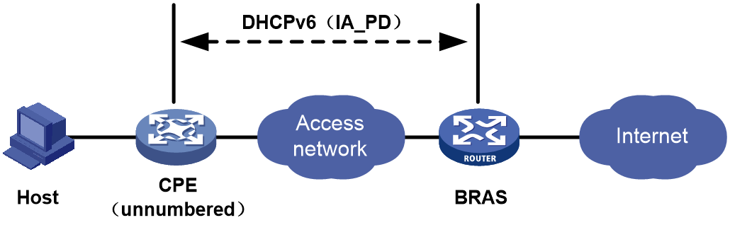
DHCPv6 (IA_PD)
As shown in Figure 33, the CPE operates in unnumbered routing mode. The BRAS device assigns a prefix to the CPE, and the CPE assigns the IPv6 prefix to the host for IPv6 address generation.
· The DHCPv6 protocol uses the IA_PD option for IPv6 prefix assignment. This option carries IA prefix information.
· The CPE a connection to the BRAS, and the BRAS device assigns a prefix to the CPE by the DHCPv6 (IA_PD) protocol. Then, the CPE assigns the obtained IPv6 prefix to the host for IPv6 address generation.
IA_NA+IA_PD
As shown in Figure 34, the CPE operates in numbered routing mode. The BRAS assigns IPv6 addresses separately to WAN port of the CPE, such as Dialer port, and assigns a prefix to the CPE for IPv6 address generation on the host.
· The BRAS uses the DHCPv6 protocol for address assignment to the WAN ports of the CPE, and assigns an IPv6 prefix to the home LAN by using the DHCPv6-PD protocol. The CPE uses the DHCPv6 protocol to assign the obtained IPv6 prefix to the host for IPv6 address generation. The CPE routes IPv6 packets when it forwards IPv6 packets.
· The CPE initiates a connection to the BRAS. The BRAS assigns IPv6 addresses to WAN ports of the CPE by using the DHCPv6 (IA_NA) protocol, and assigns a prefix to the CPE by using the DHCPv6 (IA_PD) protocol. The host can then generate an IPv6 address based on the prefix assigned to the CPE.

NDRA
As shown in Figure 35, the CPE operates in bridge mode, and the BRAS uses the ND protocol to assign an IPv6 prefix to the host for IPv6 address generation.
· NDRA address assignment is based on the Stateless Address Autoconfiguration (SLAAC) protocol.
· Although NDRA is an address assignment protocol, the BRAS device only assigns a 64-bit IPv6 prefix to the host. The host generates the remaining 64 bits, which represent the interface ID.
· The host requests an IPv6 address, the CPE transmits the request to the BRAS, and then the BRAS assigns an IPv6 prefix to the host by using the NDRA protocol.

NDRA+DHCPv6 (IA_PD)
As shown in Figure 36, the CPE operates in numbered routing mode. The BRAS assigns an IPv6 address to the WAN port of the CPE by using the ND protocol and assigns a prefix to the CPE by using DHCPv6 (IA_PD) protocol. The host generates an IPv6 address based on the prefix assigned to the CPE.
· The CPE sends a DHCPv6 packet to the BRAS to request an IPv6 prefix for the home LAN. The DHCPv6 request carries only the IA_PD option. The BRAS returns an RA message whose PIO option carries the IPv6 prefix assigned to the WAN port of the CPE. The WAN port uses the obtained IPv6 prefix to generate its IPv6 address.
· The CPE initiates a connection to the BRAS. The BRAS assigns an IPv6 prefix to the WAN port of the CPE by using the NDRA protocol, and assigns a prefix to the CPE by using the DHCPv6 (IA_PD) protocol. The host generates an IPv6 address based on the prefix assigned to the CPE.

Restrictions and guidelines
If an ND prefix pool is used to allocate prefixes to users (in the one prefix per user scenario), the following restrictions apply to these users:
· These users cannot be leased users, including interface-leased users, subnet-leased users, and L2VPN-leased users.
· The ICMPv6 detection method is not supported.
· Prefixes of these users cannot be configured for static IPoE users.
· On an access interface of these users, you cannot configure an IPv6 global unicast address.
· On an access interface of an IPoE user exclusively using a prefix, you cannot configure an IPv6 global unicast address.
In DHCPv6 (IA_PD) method, you cannot configure an IPv6 global unicast address on the access interface of a user.
IP address acquisition methods
Introduction
This chapter introduces the common methods used for IP address acquisition in IPoE, PPPoE, or L2TP networks:
· The BRAS acts as the DHCP server
· The BRAS acts as the DHCP relay agent
The IP address pools that appear in this chapter are defined as follows:
· Ordinary IP address pools: IP address pools created by the ip pool pool-name command or the ipv6 pool pool-name command. This type of IP address pools can be further divided into the following:
¡ Ordinary local IP address pools—Ordinary IP address pools that are not configured with the remote-server command.
¡ Ordinary remote IP address pools—Ordinary IP address pools that are configured with the remote-server command.
· Local BAS IP address pools: IP address pools created by the ip pool pool-name bas local command.
· Remote BAS IP address pools: IP address pools created by the ip pool pool-name bas remote command.
The BRAS acts as the DHCP server
Network configuration
As shown in Figure 37, the Layer 2 switch connects the host and the BRAS. The BRAS acts as the DHCP server for user address assignment.
Figure 37 The BRAS acts as the DHCP server

Figure 38 takes the NAS-initiated mode as an example. The remote host accesses the LNS via the LAC. An L2TP tunnel exists between the LAC and the LNS, which enables the remote host to access the company's headquarters. The LNS acts as the DHCP server for IP address assignment to the remote host.
Figure 38 The LNS acts as the DHCP server

|
|
NOTE: In this networking model, you need to create an ordinary IP address pool or local BAS IP address pool on the BRAS or LNS. For better readability, configurations of different IP address pools are introduced separately. You can see "IP address acquisition from ordinary local IP address pools" and "IP address acquisition from local BAS IP address pools". |
IP address acquisition from ordinary local IP address pools
Ordinary local IPv4 address pools
|
IP address acquisition method |
Restrictions and guidelines |
|
Authorization IPv4 address pool |
· Do not configure any IP addresses for the user-facing interface and the VT interface bound to the user-facing interface. · In the L2TP LNS scenario, do not configure any IP address for the VT interface used by the L2TP group (VT interface specified in the allow l2tp command under L2TP group view). · When you configure the gateway-list command in the authorization IPv4 address pool, you must specify the export-route keyword. |
|
Authorization IPv4 address pool group |
· Do not configure any IP addresses for the user-facing interface and the VT interface bound to the user-facing interface. · In the L2TP LNS scenario, do not configure any IP address for the VT interface used by the L2TP group (VT interface specified in the allow l2tp command under L2TP group view). · When you configure the gateway-list command in any member of the authorization IPv4 address pool group, you must specify the export-route keyword. |
Ordinary local IPv6 address pools
|
IP address acquisition method |
Restrictions and guidelines |
|
Authorization IPv6 address pool |
· You must configure the ipv6 address auto link-local command to enable automatic link-local address generation on the user-facing interface. Do not configure any IPv6 global unicast addresses for the user-facing interface and the VT interface bound to the user-facing interface. · In the L2TP LNS scenario, follow these restrictions and guidelines: ¡ You must configure the ipv6 address auto link-local command to enable automatic link-local address generation on the VT interface used by the L2TP group (VT interface specified in the allow l2tp command under L2TP group view). ¡ Do not configure any IPv6 global unicast address for the VT interface. |
|
Authorization IPv6 address pool group |
· You must configure the ipv6 address auto link-local command to enable automatic link-local address generation on the user-facing interface. Do not configure any IPv6 global unicast addresses for the user-facing interface and the VT interface bound to the user-facing interface. · In the L2TP LNS scenario, follow these restrictions and guidelines: ¡ You must configure the ipv6 address auto link-local command to enable automatic link-local address generation on the VT interface used by the L2TP group (VT interface specified in the allow l2tp command under L2TP group view). ¡ Do not configure any IPv6 global unicast address for the VT interface. |
|
Authorization ND prefix pool (Use this method when each user requires a different prefix.) |
· You must configure the ipv6 address auto link-local command to enable automatic link-local address generation on the user-facing interface. Do not configure any IPv6 global unicast addresses for the user-facing interface and the VT interface bound to the user-facing interface. · In the L2TP LNS scenario, follow these restrictions and guidelines: ¡ You must configure the ipv6 address auto link-local command to enable automatic link-local address generation on the VT interface used by the L2TP group (VT interface specified in the allow l2tp command under L2TP group view). ¡ Do not configure any IPv6 global unicast address for the VT interface. |
|
Authorization ND prefix pool group (Use this method when each user requires a different prefix.) |
· You must configure the ipv6 address auto link-local command to enable automatic link-local address generation on the user-facing interface. Do not configure any IPv6 global unicast addresses for the user-facing interface and the VT interface bound to the user-facing interface. · In the L2TP LNS scenario, follow these restrictions and guidelines: ¡ You must configure the ipv6 address auto link-local command to enable automatic link-local address generation on the VT interface used by the L2TP group (VT interface specified in the allow l2tp command under L2TP group view). ¡ Do not configure any IPv6 global unicast address for the VT interface. |
IP address acquisition from local BAS IP address pools
Local BAS IPv4 address pools
|
IP address acquisition method |
Restrictions and guidelines |
|
Authorization IPv4 address pool |
· Do not configure any IP addresses for the user-facing interface and the VT interface bound to the user-facing interface. · In the L2TP LNS scenario, do not configure any IP address for the VT interface used by the L2TP group (VT interface specified in the allow l2tp command under L2TP group view). |
|
Authorization IPv4 address pool group |
· Do not configure any IP addresses for the user-facing interface and the VT interface bound to the user-facing interface. · In the L2TP LNS scenario, do not configure any IP address for the VT interface used by the L2TP group (VT interface specified in the allow l2tp command under L2TP group view). |
Local BAS IPv6 address pools
This scenario is not supported, because BAS IPv6 address pools do not exist.
The BRAS acts as the DHCP relay agent
Network configuration
As shown in Figure 37, the Layer 2 switch connects the host and the BRAS. The BRAS acts as the DHCP relay agent to obtain user IP addresses from the remote DHCP server.
Figure 39 The BRAS acts as the DHCP relay agent
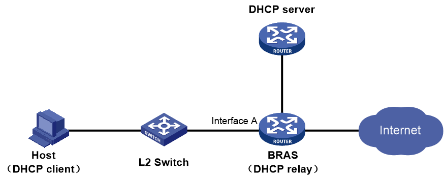
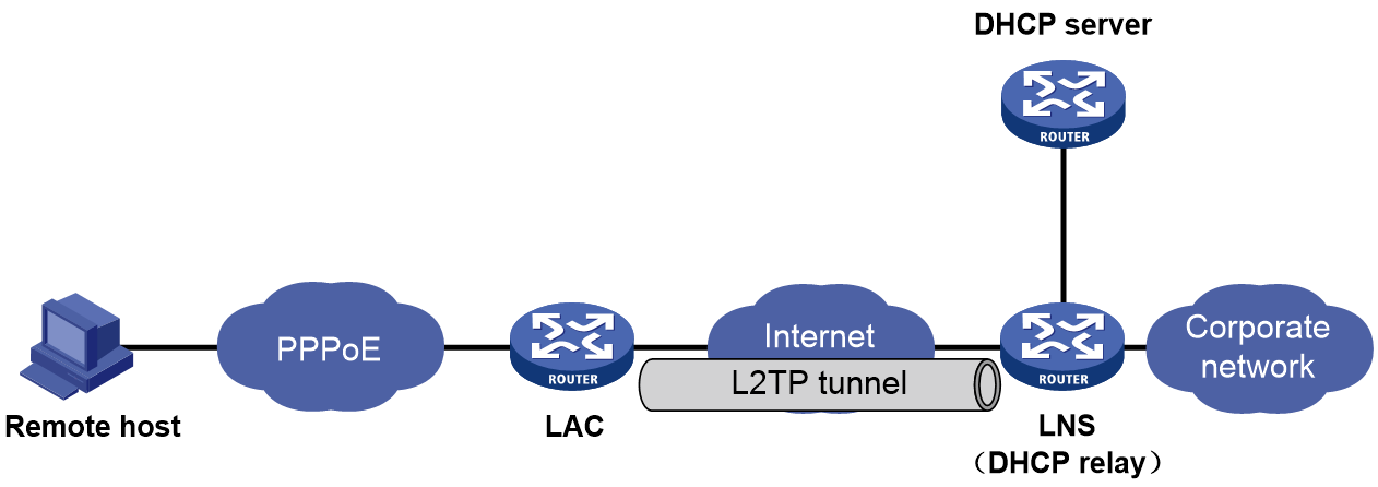
Figure 38 takes the NAS-initiated mode as an example. The remote host accesses the LNS via the LAC. An L2TP tunnel exists between the LAC and the LNS, which enables the remote host to access the company's headquarters. The LNS acts as the DHCP relay agent to obtain an IP address for the remote host from the remote DHCP server.
Figure 40 The LNS acts as the DHCP relay agent
|
|
NOTE: In this networking model, you need to create an ordinary remote IP address pool or remote BAS IP address pool on the BRAS or LNS. For better readability, configurations of different IP address pools are introduced separately. You can see "IP address acquisition from ordinary remote IP address pools" and "IP address acquisition from remote BAS IP address pools". |
IP address acquisition from ordinary remote IP address pools
Ordinary remote IPv4 address pools
|
IP address acquisition method |
Restrictions and guidelines |
|
Authorization IPv4 address pool |
· Do not configure any IP addresses for the user-facing interface and the VT interface bound to the user-facing interface. · In the L2TP LNS scenario, do not configure any IP address for the VT interface used by the L2TP group (VT interface specified in the allow l2tp command under L2TP group view). · When you configure the gateway-list command in the authorization IPv4 address pool, you must specify the export-route keyword. |
|
Authorization IPv4 address pool group |
· Do not configure any IP addresses for the user-facing interface and the VT interface bound to the user-facing interface. · In the L2TP LNS scenario, do not configure any IP address for the VT interface used by the L2TP group (VT interface specified in the allow l2tp command under L2TP group view). · When you configure the gateway-list command in any member of the authorization IPv4 address pool group, you must specify the export-route keyword. |
Ordinary remote IPv6 address pools
|
IP address acquisition method |
Restrictions and guidelines |
|
Authorization IPv6 address pool |
· You must configure the ipv6 address auto link-local command to enable automatic link-local address generation on the user-facing interface. Do not configure any IPv6 global unicast addresses for the user-facing interface and the VT interface bound to the user-facing interface. · In the L2TP LNS scenario, follow these restrictions and guidelines: ¡ You must configure the ipv6 address auto link-local command to enable automatic link-local address generation on the VT interface used by the L2TP group (VT interface specified in the allow l2tp command under L2TP group view). ¡ Do not configure any IPv6 global unicast address for the VT interface. |
|
Authorization IPv6 address pool group |
· You must configure the ipv6 address auto link-local command to enable automatic link-local address generation on the user-facing interface. Do not configure any IPv6 global unicast addresses for the user-facing interface and the VT interface bound to the user-facing interface. · In the L2TP LNS scenario, follow these restrictions and guidelines: ¡ You must configure the ipv6 address auto link-local command to enable automatic link-local address generation on the VT interface used by the L2TP group (VT interface specified in the allow l2tp command under L2TP group view). ¡ Do not configure any IPv6 global unicast address for the VT interface. |
IP address acquisition from remote BAS IP address pools
Remote BAS IPv4 address pools
|
IP address acquisition method |
Restrictions and guidelines |
|
Authorization IPv4 address pool |
· Do not configure any IP addresses for the user-facing interface and the VT interface bound to the user-facing interface. · In the L2TP LNS scenario, do not configure any IP address for the VT interface used by the L2TP group (VT interface specified in the allow l2tp command under L2TP group view). |
|
Authorization IPv4 address pool group |
· Do not configure any IP addresses for the user-facing interface and the VT interface bound to the user-facing interface. · In the L2TP LNS scenario, do not configure any IP address for the VT interface used by the L2TP group (VT interface specified in the allow l2tp command under L2TP group view). |
Remote BAS IPv6 address pools
This scenario is not supported, because BAS IPv6 address pools do not exist.
Key configurations
Configuring global static dual-stack users
Commands
Syntax 1
· Configure a dual-stack global static IPoE session:
ip subscriber session static ip start-ipv4-address [ end-ipv4-address ] ipv6 start-ipv6-address [ end-ipv6-address ] [ delegation-prefix start-ipv6-prefix [ end-ipv6-prefix ] prefix-length ] [ mac mac-address ] [ domain domain-name ] [ password mac ] [ interface interface-type interface-number [ vlan vlan-id [ second-vlan vlan-id ] ] [ request-online [ ip | ipv6 ] ] ] [ description string ] [ gateway { ip ipv4-address | ipv6 ipv6-address } * ] [ vpn-instance vpn-instance-name ] [ keep-online ]
Syntax 2
· Configure a dual-stack global static IPoE session:
ip subscriber session static ip start-ipv4-address [ end-ipv4-address ] ipv6 start-ipv6-address [ end-ipv6-address ] interface-list list-id [ delegation-prefix start-ipv6-prefix [ end-ipv6-prefix ] prefix-length ] [ mac mac-address ] [ domain domain-name ] [ password mac ] [ description string ] [ vpn-instance vpn-instance-name ] [ keep-online ]
Application scenarios
This feature is applicable in the government/enterprise leased line scenario where static users are used as static leased line users.
Usage guidelines
About this task
This type of dual-stack users come online as static users in both the IPv4 protocol stack and IPv6 protocol stack.
· For the IPv4 protocol stack, users can initiate coming online as static users through IPv4 packets or Address Resolution Protocol (ARP) packets.
· For the IPv6 protocol stack, users can initiate coming online as static users through IPv6 packets, Neighbor Solicitation (NS) packets, or Neighbor Advertisement (NA) packets.
Restrictions and guidelines
· In a global static session, the IPv4 addresses and IPv6 addresses specified for dual-stack users must correspond in one-one mode.
· IPv4 addresses are in dotted decimal notation, and IPv6 addresses are in hexadecimal notation. For example, IPv4 addresses 1.1.1.1 through 1.1.1.100 can correspond to IPv6 addresses 1::1 through 1::64 but cannot correspond to IPv6 addresses 1::1 to 1::100.
Configuration examples
# In system view, configure a dual-stack global static IPoE session.
<Sysname> system-view
[Sysname] ip subscriber session static ip 1.1.1.1 1.1.1.100 ipv6 1::1 1::64 domain dm1 interface route-aggregation 1
Configuring Web authentication fail-permit
Commands
Use ip subscriber pre-auth track track-entry-number fail-permit user-group group-name to associate a fail-permit user group with a track entry.
Application scenarios
This feature is applicable in scenarios where you configure Web authentication fail-permit for users when the device detects that the Web authentication server or AAA server is unreachable (because of server malfunctions or route unreachability.)
Usage guidelines
About this task
With this feature configured, when the device detects that the Web authentication server or AAA server is unreachable, the device allows users to access network resources without Web authentication. This process is called Web authentication fail-permit. You can implement Web authentication fail-permit by associating a fail-permit user group with a track entry.
By default, the Web authentication users that come online in the preauthentication domain belong to the user group authorized by AAA or authorized in the ISP domain when the users come online. After a fail-permit user group is associated with a track entry, the following rules apply:
· When the status of the track entry becomes Negative, the BRAS device moves all online users in the current preauthentication domain from the authorized user group to the fail-permit user group. Then, the users can access network resources according to the privilege of the fail-permit user group.
· When the status of the track entry becomes Positive, the BRAS device will move all online users in the current preauthentication domain back to the authorized user group. Then, the users can access network resources only after passing Web authentication.
Restrictions and guidelines
To monitor the status of multiple servers, you can configure the tracked object list.
This feature takes effect only on users in the preauthentication domain.
If you execute the ip subscriber pre-auth track track-entry-number fail-permit user-group group-name command multiple times, the most recent configuration takes effect.
Examples
· Configure an NQA operation with administrator name admin and operation tag test1.
<Sysname> system-view
# Create an NQA operation with administrator name admin and operation tag test1.
[Sysname] nqa entry admin test1
# Configure the NQA operation type as ICMP echo.
[Sysname-nqa-admin-test1] type icmp-echo
# Specify 4.4.4.5 as the destination IP address.
[Sysname-nqa-admin-test1-icmp-echo] destination ip 4.4.4.5
# Configure the operation to repeat every 100 milliseconds.
[Sysname-nqa-admin-test1-icmp-echo] frequency 100
# Create reaction entry 1. If the number of consecutive probe failures reaches 5, collaboration is triggered.
[Sysname-nqa-admin-test1-icmp-echo] reaction 1 checked-element probe-fail threshold-type consecutive 5 action-type trigger-only
[Sysname-nqa-admin-test1-icmp-echo] quit
# Start the ICMP echo operation.
[Sysname] nqa schedule admin test1 start-time now lifetime forever
· Configure an NQA operation with administrator name admin and operation tag test2.
# Create an NQA operation with administrator name admin and operation tag test2.
[Sysname] nqa entry admin test2
# Configure the NQA operation type as ICMP echo.
[Sysname-nqa-admin-test2] type icmp-echo
# Specify 4.4.4.6 as the destination IP address.
[Sysname-nqa-admin-test2-icmp-echo] destination ip 4.4.4.6
# Configure the operation to repeat every 100 milliseconds.
[Sysname-nqa-admin-test2-icmp-echo] frequency 100
# Create reaction entry 2. If the number of consecutive probe failures reaches 5, collaboration is triggered.
[Sysname-nqa-admin-test2-icmp-echo] reaction 2 checked-element probe-fail threshold-type consecutive 5 action-type trigger-only
[Sysname-nqa-admin-test2-icmp-echo] quit
# Start the ICMP echo operation.
[Sysname] nqa schedule admin test2 start-time now lifetime forever
· Create track entries.
# Create track entry 1, and associate it with reaction entry 1 of the NQA operation with administrator name admin and operation tag test1.
[Sysname] track 1 nqa entry admin test1 reaction 1
# Create track entry 2, and associate it with reaction entry 2 of the NQA operation with administrator name admin and operation tag test2.
[Sysname] track 2 nqa entry admin test2 reaction 2
· Configure a Boolean tracked list.
# Create Boolean AND list 100 and enter its view.
[Sysname] track 100 list boolean and
# Add track entries 1 and 2 as tracked objects to the list.
[Sysname-track-100] object 1
[Sysname-track-100] object 2
· Create a local user group named flee.
[BRAS] user-group flee
New user group added.
[BRAS-ugroup-flee] quit
· Associate fail-permit user group flee with Boolean tracked list 100 on Ten-GigabitEthernet 3/1/1.
[Sysname] interface ten-gigabitethernet 3/1/1
[Sysname-Ten-GigabitEthernet3/1/1] ip subscriber pre-auth track 100 fail-permit user-group flee
AAA fail-permit and recovery
Commands
· Use authen-radius-unavailable online domain new-isp-name to specify a critical domain for an ISP domain to accommodate users that access the ISP domain when all RADIUS servers are unavailable.
· Use authen-radius-recover { offline | online domain new-isp-name } to specify the action to take on users in the critical domain when a RADIUS server in the users' original authentication domain becomes available.
· Use radius-server authen-state-check interval interval to set the interval at which the device detects the status of RADIUS authentication servers.
Application scenarios
Suitable to scenarios where fail-permit is required for users when the AAA server is unavailable or cannot be reached.
Usage guidelines
About this task
This feature is used to resolve the issue that users that use a RADIUS scheme cannot come online when all RADIUS servers in the RADIUS scheme are unavailable. The feature contains the following settings in a user authentication domain:
In the user authentication domain, specify a critical domain (also known as fail-permit domain) to accommodate users that access the authentication domain when all RADIUS servers are unavailable. The users can come online in the critical domain without being authenticated when all RADIUS servers are unavailable.
In the user authentication domain, specify an action to take on users that have been assigned to the critical domain when a RADIUS server for the authentication domain becomes available.
· To perform authentication, authorization, and accounting for the users, log off the users.
· To assign the users back to the authentication domain, allow the users to stay online and specify the authentication domain as the recovery domain. The device does not perform authentication, authorization, or accounting for the users after the users are assigned to the recovery domain. The users can obtain the effective authorization attributes in the recovery domain. To specify the effective authorization attributes, use the dynamic-authorization effective-attribute command.
For the device to obtain the status of RADIUS authentication servers in time, it detects the status of the RADIUS authentication servers in each RADIUS scheme at intervals. In addition, the device notifies access modules to remove users that use a RADIUS scheme from the critical domain when that RADIUS scheme has reachable RADIUS servers.
Restrictions and guidelines
This feature takes effect only on IPoE and PPPoE users.
The action to take on users in the critical domain when a RADIUS server in the users' original authentication domain becomes available is online for fail-permit recovery in the IPoE Web preauthentication domain and offline for fail-permit recovery in the Web postauthentication domain.
When you specify a critical domain for an ISP domain, follow these restrictions and guidelines:
· If non-none authentication, authorization, or accounting methods are configured in the critical domain for an ISP domain, the non-none authentication or authorization methods cannot take effect on users. However, the non-none accounting methods in the critical domain can take effect on users.
· If an ISP domain has been specified as a critical domain, do not specify a critical domain for that ISP domain. If you do so, the critical domain specified for that ISP domain cannot take effect. If a critical domain has been specified for an ISP domain, do not specify that ISP domain as a critical domain. If you do so, that ISP domain cannot act as a critical domain.
· To delete an ISP domain that has been specified as the critical domain, you must first use undo authen-radius-unavailable online domain command to remove the critical domain setting from the ISP domain.
When you specify a recovery domain for an ISP domain, follow these restrictions and guidelines:
· If the none method is configured as the backup authentication method in the original authentication domain before the users are assigned to the critical domain, the users still can be assigned to the recovery domain when a RADIUS server becomes available.
· As a best practice to accurately identify whether a RADIUS authentication server is available and the recovery configuration can take effect in time, configure RADIUS server status detection.
· If you do not specify the original authentication domain as the recovery domain, users in the critical domain are assigned to the recovery domain after a RADIUS server becomes available. However, the device does not perform authentication, authorization, or accounting for the users.
· To delete an ISP domain that has been specified as the recovery domain, you must first use the undo authen-radius-recover command to remove the recovery domain setting from the ISP domain.
When you set the interval at which the device detects the status of RADIUS authentication servers, follow these restrictions and guidelines:
· A too short detection interval consumes too many system resources for access services. A too long detection interval cannot detect server status changes in time.
· As a best practice, consider the processing efficiency for access services and the accuracy for fail-permit and recovery when a large number of users come online in a short time.
Examples
# In ISP domain test, specify the critical domain as dm1, and log off users in the critical domain when a RADIUS server in the users' original authentication domain becomes available.
<Sysname> system-view
[Sysname] domain name test
[Sysname-isp-test] authen-radius-unavailable online domain dm1
[Sysname-isp-test] authen-radius-recover offline
[Sysname-isp-test] quit
# Configure the device to detect the status of RADIUS authentication servers at intervals of 2 minutes.
[Sysname] radius-server authen-state-check interval 2
Enabling the DHCPv6 relay agent to support Option 79
Commands
Use ipv6 dhcp relay client-link-address enable to enable the DHCPv6 relay agent to support Option 79.
Application scenarios
Perform this task on cross-Layer 3 networks to ensure that users need to pass authentication only once in the IPv4/IPv6 dual-stack scenario.
Usage guidelines
About this tasks
If DHCPv6 relay agents exist in the network, the DHCPv6 server needs the MAC address of a DHCPv6 client for authentication, IPv6 address assignment, prefix assignment, or assignment of other network settings. To meet the requirement, enable the DHCPv6 relay agent that the client first passes to support Option 79. This feature allows the DHCPv6 relay agent to learn the MAC address in the client request. When the relay agent generates a Relay-Forward packet for the request, it fills the MAC address of the client in Option 79. The Relay-Forward packet is then forwarded to the DHCPv6 server.
Restrictions and guidelines
You can configure this feature on cross-Layer 3 networks. To ensure that users need to pass authentication only once in the IPv4/IPv6 dual-stack scenario, perform the following tasks:
· Enable the DHCPv6 relay agent to support Option 79 by using the ipv6 dhcp relay client-link-address enable command.
· Configure Option 79 as a trusted option on the BRAS device by using the ip subscriber trust option79 command.
Examples
# On Ten-GigabitEthernet 3/1/1, enable the relay agent to support Option 79.
<Sysname> system-view
[Sysname] interface ten-gigabitethernet 3/1/1
[Sysname-Ten-GigabitEthernet3/1/1] ipv6 dhcp relay client-link-address enable
Configuring trusted DHCP options for DHCP users
Commands
Use ip subscriber trust { option12 | option60 | option77 | option82 | option16 | option17 | option18 | option37 | option79 } to configure a trusted DHCP option for DHCP users.
Application scenarios
Perform this task when a DHCP option is required for special purposes. For example, configure Option 79 as a trusted option on cross-Layer 3 networks when it is used to ensure that the IPv4/IPv6 dual-stack scenario requires each user to pass authentication only once.
Usage guidelines
About this tasks
By default, only Option 79 is trusted and other DHCP options are not trusted. To use an untrusted DHCP option, first perform this task to configure the option as a trusted option.
Restrictions and guidelines
You can configure this feature on cross-Layer 3 networks. To ensure that users need to pass authentication only once in the IPv4/IPv6 dual-stack scenario, perform the following tasks:
· Enable the DHCPv6 relay agent to support Option 79 by using the ipv6 dhcp relay client-link-address enable command.
· Configure Option 79 as a trusted option on the BRAS device by using the ip subscriber trust option79 command.
Examples
# On Ten-GigabitEthernet 3/1/1, configure Option 79 as a trusted option.
<Sysname> system-view
[Sysname] interface ten-gigabitethernet 3/1/1
[Sysname-Ten-GigabitEthernet3/1/1] ip subscriber trust option79
Enabling the DHCP server to return a DHCP-NAK message upon client notions of incorrect IP addresses
Commands
Use dhcp server request-ip-address check to enable the DHCP server to return a DHCP-NAK message if the client notions of their IP addresses are incorrect.
Application scenarios
Perform this task on networks where DHCP is used for address assignment.
Usage guidelines
About this task
A DHCP client can send a DHCP-REQUEST message directly or upon receiving a DHCP-OFFER message. Upon receiving the request, the DHCP server will check if the client notion of its IP address is correct. If the requested IP address is different from the allocated one or has no matching lease record, the DHCP server remains silent by default. After the allocated IP address lease for the client expires, the DHCP server will make response to request from the client.
This feature enables the DHCP server to return DHCP-NAK messages if the client notions of their IP addresses are incorrect. After receiving the DHCP-NAK message, the DHCP client will request an IP address again.
Recommended configurations
Configure this feature for all of the DHCP servers on the BRAS networking model.
Examples
# Enable the DHCP server to return a DHCP-NAK message if the client notions of their IP addresses are incorrect.
<Sysname> system-view
[Sysname] dhcp server request-ip-address check
Configuring L2TP LNS load sharing
Commands
· Use tunnel load-sharing to configure a LAC to operate in load sharing mode.
· Use lns-ip { ip-address [ weight lns-weight ] }&<1-5> to specify LNS IP addresses.
¡ ip-address: Specifies LNS IP addresses.
¡ weight lns-weight: Specifies the weight of an LNS, in the range of 1 to 10. The default weight is 5. The larger the weight, the higher the priority. This parameter takes effect only if the LAC is operating in load balancing mode.
¡ &<1-5> indicates that you can enter a maximum of five IP addresses.
Application scenarios
Use this feature for multiple LNSs to load share service traffic in an L2TP network.
Usage guidelines
About this task
You can specify up to five LNS IP addresses for an LAC. An LAC can operate in master/backup mode or load sharing mode.
· Master/backup mode—When the lns-ip command is executed to configure multiple LNS addresses, the LAC tries to establish a connection to an LNS in the LNS address configuration order until a connection to an LNS is successfully established. The LNS that successfully establishes a connection is called the master LNS, and the other LNSs are backup LNSs. An LAC tries to establish a connection to a backup LNS until the master LNS fails.
· Load sharing mode—When the lns-ip command is executed to configure multiple LNS addresses, the LAC distributes the L2TP services among the specified LNSs according to their weights.
Restrictions and guidelines
If you perform this task multiple times for a L2TP group, the most recent configuration takes effect.
Examples
# Configure the LAC to operate in load sharing mode. Set the weight to 6 for the LNS at 1.1.1.1 and 3 for the LNS at 2.2.2.2.
<Sysname> system-view
[Sysname] l2tp-group 1 mode lac
[Sysname-l2tp1] tunnel load-sharing
[Sysname-l2tp1] lns-ip 1.1.1.1 weight 6 2.2.2.2 weight 3
Configuring the captive-bypass feature
Commands
Use ip subscriber captive-bypass enable [ android | ios ] [ optimize ] to enable the captive-bypass feature.
· android: Specifies Android users.
· ios: Specifies iOS users.
· optimize: Enables captive-bypass optimization.
Application scenarios
This feature is applicable in scenarios where you configure the device to push the Web authentication page only when a user in the network accesses the Internet by using a browser.
Usage guidelines
About this task
By default, the device automatically pushes the Web authentication page to the iOS devices and some Android devices when they are connected to the network with IPoE Web authentication enabled. With the captive-bypass feature enabled, the device does not automatically push the Web authentication page to iOS devices and some Android devices when they are connected to the network. The device pushes the Web authentication page only when the user accesses the Internet by using a browser.
Restrictions and guidelines
The captive-bypass optimization feature takes effect only on iOS users and does not take effect on Android users.
With the captive-bypass optimization feature enabled, when an iOS user uses a browser to access the Internet, the Web authentication page automatically opens. When the user does not perform authentication and presses the home button to return to the home screen, the Wi-Fi connection is not disconnected.
When you execute this command without specifying any keyword, this command enables the captive-bypass feature for both Android users and iOS users. If you specify only the optimize keyword, this command enables the captive-bypass feature for Android users and the captive-bypass optimization feature for iOS users.
Examples
# Enable the captive-bypass feature.
<Sysname> system-view
[Sysname] interface ten-gigabitethernet 3/1/1
[Sysname-Ten-GigabitEthernet3/1/1] ip subscriber captive-bypass enable
# Enable the captive-bypass optimization feature for iOS users.
<Sysname> system-view
[Sysname] interface ten-gigabitethernet 3/1/1
[Sysname-Ten-GigabitEthernet3/1/1] ip subscriber captive-bypass enable ios optimize
# Enable the captive-bypass feature for Android users.
<Sysname> system-view
[Sysname] interface ten-gigabitethernet 3/1/1
[Sysname-Ten-GigabitEthernet3/1/1] ip subscriber captive-bypass enable android
Configuring interface-based ARP attack suppression
Commands
· Use arp attack-suppression enable per-interface to enable interface-based ARP attack suppression.
· Use arp attack-suppression check-interval interval to set the check interval for interface-based ARP attack suppression.
· Use arp attack-suppression threshold threshold-value to set the threshold for triggering interface-based ARP attack suppression.
· Use arp attack-suppression suppression-time time to set the interface-based ARP attack suppression time.
Application scenarios
This feature is applicable to scenarios configured with interface-based ARP attack protection.
Usage guidelines
About this task
Use this feature to rate limit ARP requests on each Layer 3 interface to prevent ARP spoofing attacks.
This feature monitors the number of ARP requests that each Layer 3 interface received within the check interval. If the number on an interface exceeds the ARP attack suppression threshold, the device creates an ARP attack suppression entry for the interface. Before the suppression time for the entry times out, the maximum receiving rate for ARP packets is limited on the interface.
During the suppression period, the device monitors the number of received ARP requests on the interface:
· If the number of the received ARP requests is higher than or equal to a calculated value, the device determines that the ARP attack still exists on the interface. When the suppression time expires, the device resets the suppression time for the entry and continues the ARP suppression on the interface.
The calculated value = (suppression time/check interval) × suppression threshold
· If the number of the received ARP requests is lower than the calculated value, the ARP suppression entry is deleted when the suppression time expires.
Restrictions and guidelines
This feature takes effect only on Layer 3 Ethernet interfaces and Layer 3 Ethernet subinterfaces.
Examples
# Enable interface-based ARP attack suppression.
<Sysname> system-view
[Sysname] arp attack-suppression enable per-interface
# Set the check interval for interface-based ARP attack suppression to 30 seconds.
[Sysname] arp attack-suppression check-interval 30
# Set the interface-based ARP attack suppression threshold to 1000.
[Sysname] arp attack-suppression threshold 1000
# Set the interface-based ARP attack suppression time to 60 seconds.
[Sysname] arp attack-suppression suppression-time 60
Configuring interface-based ND attack suppression
Commands
· Use ipv6 nd attack-suppression enable per-interface to enable interface-based ND attack suppression.
· Use ipv6 nd attack-suppression check-interval interval to set the check interval for interface-based ND attack suppression.
· Use ipv6 nd attack-suppression threshold threshold-value to set the threshold for triggering interface-based ND attack suppression.
· Use ipv6 nd attack-suppression suppression-time time to set the interface-based ND attack suppression time.
Application scenarios
This feature is applicable to scenarios configured with interface-based ND attack protection.
Usage guidelines
About this task
Use this feature to rate limit ND requests on each Layer 3 interface to prevent ND spoofing attacks.
This feature monitors the number of ND requests that each Layer 3 interface received within the check interval. If the number on an interface exceeds the ND attack suppression threshold, the device creates an ND attack suppression entry for the interface. Before the suppression time for the entry times out, the maximum receiving rate for ND messages is limited on the interface.
During the suppression period, the device monitors the number of received ND messages on the interface:
· If the number of the received ND messages is higher than or equal to a calculated value, the device determines that the ND attack still exists on the interface. When the suppression time expires, the device resets the suppression time for the entry and continues the ND suppression on the interface.
The calculated value = (suppression time/check interval) × suppression threshold
· If the number of the received ND messages is lower than the calculated value, the ND suppression entry is deleted when the suppression time expires.
Restrictions and guidelines
This feature takes effect only on Layer 3 Ethernet interfaces and Layer 3 Ethernet subinterfaces.
Examples
# Enable interface-based ND attack suppression.
<Sysname> system-view
[Sysname] ipv6 nd attack-suppression enable per-interface
# Set the check interval to 30 seconds for interface-based ND attack suppression.
[Sysname] ipv6 nd attack-suppression check-interval 30
# Set the threshold to 500 for triggering interface-based ND attack suppression.
[Sysname] ipv6 nd attack-suppression threshold 500
# Set the suppression time to 60 seconds for interface-based ND attack suppression.
[Sysname] ipv6 nd attack-suppression suppression-time 60
Configuring DHCP attack protection
Commands
· Use dhcp flood-protection enable to enable DHCP flood attack protection.
· Use ipv6 dhcp flood-protection enable to enable DHCPv6 flood attack protection.
Application scenarios
This configuration is applicable to Layer 2 networks configured with DHCP attack protection.
Usage guidelines
About this task
DHCP flood attack protection enables the DHCP server to detect DHCP flood attacks according to the DHCP packet rate threshold on a per-MAC basis.
When the DHCP server receives a DHCP packet from a client (MAC address), it creates a DHCP flood attack entry in check state. If the number of DHCP packets from the same MAC address reaches the upper limit in the detection duration, the server determines that the client is launching a DHCP flood attack. The DHCP flood attack entry changes to the restrain state, and the DHCP server discards the DHCP packets from that client.
Restrictions and guidelines
On a Layer 3 network, the source MAC addresses of DHCP packets received by the same access interface on a BRAS device are the same. To prevent the BRAS device from intercepting normal packets and affecting user access, do not enable this feature on user access interfaces of BRAS devices.
Examples
# Enable DHCP and DHCPv6 flood attack protection on Ten-GigabitEthernet 3/1/1.
<Sysname> system-view
[Sysname] interface ten-gigabitethernet 3/1/1
[Sysname-Ten-GigabitEthernet3/1/1] dhcp flood-protection enable
[Sysname-Ten-GigabitEthernet3/1/1] ipv6 dhcp flood-protection enable
Configuring IPoE web support for HTTP/HTTPS attack defense
Commands
Use ip subscriber http-defense destination-ip enable [ action { block [ period blocking-period ] | logging } ] command to enable destination IP-based IPoE HTTP/HTTPS attack defense.
Use ip subscriber http-defense destination-ip threshold packet-number interval interval command to configure the threshold for triggering IPoE HTTP/HTTPS attack defense.
Use ip subscriber http-defense free-destination-ip { ipv4-address | ipv6 ipv6-address } [ vpn-instance vpn-instance-name ] command to configure the allowlist addressees for IPoE HTTP/HTTP attack defense.
Application scenarios
This feature is applicable in scenarios where you configure IPoE web support for HTTP/HTTPS attack defense.
Usage guidelines
About this task
When various tool software products (for example, Baidu cloud) are installed on a client, each tool software product will periodically send HTTP/HTTPS requests to a fixed destination IP address. HTTP/HTTPS requests generated by these tool software products will result in high resource usage before users perform IPoE Web authentication. As a result, the authentication efficiency of users is affected, and the authentication might even fail. To resolve this issue, you can enable destination IP-based IPoE HTTP/HTTPS attack defense. Use the attack defense function in the following scenarios:
· To limit the HTTP/HTTPS requests frequently initiated and reduce the resource usage of these massive HTTP/HTTPS packets, use the ip subscriber http-defense destination-ip enable action block command to generate blocking entries when the blocking conditions are met and block HTTP/HTTPS requests sent to the specified destination IP addresses based on the blocking entries.
· Blocking HTTP/HTTPS requests will affect users' access to the specified destination IP addresses. To only detect the HTTP/HTTPS requests frequently initiated to the specified destination IP addresses rather than block them, use the ip subscriber http-defense destination-ip enable action logging command to output attack logs and generate attack defense blocking entries that are used to view blocked users but will not block attack packets when the blocking conditions are met. The generated attack log messages by the device will be sent to the information center. The information center configuration specifies the log message sending rule and destination. For more information about the information center, see the corresponding configuration guide of the device.
After you enable destination IP-based IPoE HTTP/HTTPS attack defense, the device will monitor and collect statistics of HTTP/HTTPS packets that IPoE Web preauthentication users send to any destination IP address. If the total number of HTTP/HTTPS packets sent to a destination IP address within a statistics collection interval exceeds the specified threshold, the device will generate blocking entries to block attack packets or output attack logs as configured by the ip subscriber http-defense destination-ip enable command.
During the packet blocking period, the device directly drops packets destined to the specified destination IP address to reduce the impact on the user onboarding speed. If the device receives packets sent to the destination IP address again after the blocking period expires, the device monitors and collects statistics of packets again.
Restrictions and guidelines
In the current software version, the IPoE HTTP/HTTPS attack defense function takes effect only on HTTP/HTTPS packets sent by IPoE Web users that have come online in the preauthentication domain.
You can use the ip subscriber http-defense free-destination-ip command to add the destination IP addresses to the allowlist when the following requirements are met:
· You do not want to collect attack defense statistics of HTTP/HTTPS packets sent by users to the specified destination IP addresses.
· You want to unconditionally push the Web authentication page to users accessing these destination IP addresses.
Examples
# Enable destination IP-based IPoE HTTP/HTTP attack defense and output attack logs when the blocking conditions are met.
<Sysname> system-view
[Sysname] ip subscriber http-defense destination-ip enable action logging
# Trigger attack defense when the total number of HTTP/HTTPS packets sent to the same destination IP address within 360 seconds reaches 5000.
[Sysname] ip subscriber http-defense destination-ip threshold 5000 interval 360
# Add IP address 1.1. 1.2 to the allowlist for IPoE HTTP/HTTPS attack defense.
[Sysname] ip subscriber http-defense free-destination-ip 1.1.1.2
ITA configuration
Specify the traffic level for accounting
Commands
Use accounting-level level { { ipv4 | ipv6 } | car { inbound cir committed-information-rate [ pir peak-information-rate ] | outbound cir committed-information-rate [ pir peak-information-rate ] } * } * to specify the traffic level for accounting.
Application scenarios
Suitable for scenarios deployed with ITA services.
Usage guidelines
About this task
By default, no traffic levels are specified for accounting.
By defining different traffic levels based on the destination addresses of users' traffic, you can use ITA to separate the traffic accounting statistics of different levels for each user.
Restrictions and guidelines
· You can execute this command multiple times to specify different traffic levels for accounting and specify different traffic monitoring parameters for different traffic levels. If you specify only the traffic monitoring parameters for a traffic level but do not specify the ipv4 or ipv6 keyword, the system does not perform accounting for traffic of the level.
· If you do not specify the level keyword when executing the undo accounting-level command, the command deletes all the specified traffic levels for the ITA policy.
· If the IP type specified by using this command is inconsistent from the actual IP type of ITA traffic, the system performs accounting on ITA traffic based on the specified IP type.
· If you do not specify the ipv4 or ipv6 keyword, the system does not perform accounting on ITA traffic.
Examples
# In ITA policy ita1, specify the traffic level 2 and 4 for IPv4 and IPv6 traffic, respectively.
<Sysname> system-view
[Sysname] ita policy ita1
[Sysname-ita-policy-ita1] accounting-level 2 ipv4
[Sysname-ita-policy-ita1] accounting-level 4 ipv6
Specify the accounting method for the ITA service
Commands
Use accounting-method { none | radius-scheme radius-scheme-name [ none ] } to specify the accounting method for an ITA policy.
Application scenarios
Suitable for scenarios where independent accounting is required for ITA service traffic.
Usage guidelines
About this task
By default, an ITA policy uses the none accounting scheme.
You can perform this task to specify an accounting scheme only for ITA traffic.
Restrictions and guidelines
You can specify a backup accounting method for the system to use when the current accounting method fails. For example, the radius-scheme radius-scheme-name none configuration indicates using the RADIUS scheme for accounting and using none scheme if the specified RADIUS scheme is invalid. Remote accounting is invalid if the specified accounting scheme does not exist, accounting packet sending fails, or the server is not responding. Local accounting is invalid if the corresponding local user configuration is not found.
Examples
# Specify accounting scheme radius1 for ITA policy ita1.
<Sysname> system-view
[Sysname] ita policy ita1
[Sysname-ita-policy-ita1] accounting-method radius-scheme radius1
Separate ITA traffic from overall accounting traffic
Commands
Use traffic-separate enable [ level level&<1-8> ] to exclude the amount of ITA traffic from the overall traffic statistics that are sent to the accounting server.
Application scenarios
Suitable for scenarios where ITA traffic is required to be separated from the overall accounting traffic.
Usage guidelines
By default, the amount of ITA traffic is included in the overall traffic statistics that are sent to the accounting server.
After you separate ITA traffic from the overall accounting traffic, the total accounting traffic reported by a BRAS device to the accounting server does not include ITA traffic of the specified level.
Examples
# In ITA policy ita1, exclude the amount of ITA traffic of level 1 from the overall traffic statistics that sent to the accounting server.
<Sysname> system-view
[Sysname] ita policy ita1
[Sysname-ita-policy-ita1] traffic-separate enable leve1 1
Configure accounting merge
Commands
Use accounting-merge enable to enable accounting merge feature.
Application scenarios
Suitable for scenarios where unified accounting is required for traffic of all accounting levels.
Usage guidelines
By default, the accounting merge feature is disabled.
When accounting merge is enabled, the device merges accounting statistics for the ITA traffic of all levels in the ITA policy. It reports the traffic as the lowest level of the policy to the accounting server.
Examples
# Enable the accounting merge feature for ITA policy ita1.
<Sysname> system-view
[Sysname] ita policy ita1
[Sysname-ita-policy-ita1] accounting-merge enable
Configure access control for users that have used up their ITA data quotas
Commands
Use traffic-quota-out { offline | online } [ no-accounting-update ] to configure access control for users that have used up their ITA data quotas.
Application scenarios
Suitable for scenarios where access control is required for users that have used up their ITA data quotas.
Usage guidelines
About this task
By default, after a user uses up its ITA data quota, the device sends accounting update requests to the server to obtain a new data quota. If the accounting response does not carry any new data quota, the user cannot access the authorized IP subnets.
Recommended configuration
If the server does not support issuing traffic quotas to online users multiple times, specify the no-accounting-update keyword when you execute this command as a best practice to reduce the burden on the server.
Examples
# In ITA policy ita1, prohibit users from accessing the authorized IP subnets after their ITA data quotas are used up.
<Sysname> system-view
[Sysname] ita policy ita1
[Sysname-ita-policy-ita1] traffic-quota-out offline
Configuring the M/O flag
Commands
· Use ipv6 nd autoconfig managed-address-flag to set the managed address configuration flag (M) to 1 in RA advertisements to be sent. Hosts receiving the advertisements use stateful autoconfiguration (for example, from a DHCPv6 server) to obtain IPv6 addresses.
· Use ipv6 nd autoconfig other-flag to set the other stateful configuration flag (O) to 1 in RA advertisements to be sent. Hosts receiving the advertisements use stateful autoconfiguration (for example, from a DHCPv6 server) to obtain configuration information other than the IPv6 addresses.
· Use undo ipv6 nd ra halt to disable RA message suppression.
Application scenarios
This feature is applicable to scenarios where hosts use stateful autoconfiguration (for example, from a DHCPv6 server) to obtain IPv6 addresses.
Usage guidelines
About this task
To simplify host configuration, IPv6 supports stateful and stateless address autoconfiguration.
· Stateful address autoconfiguration enables a host to acquire an IPv6 address and other configuration information from a server (for example, a DHCPv6 server).
· Stateless address autoconfiguration enables a host to automatically generate an IPv6 address and other configuration information by using its link-layer address and the prefix information advertised by a router.
M flag
The M flag determines whether a host uses stateful autoconfiguration to obtain an IPv6 address.
By default, the M flag is set to 0 in RA advertisements. Hosts receiving the advertisements will obtain IPv6 addresses through stateless autoconfiguration. To configure hosts to use stateful autoconfiguration (for example, from a DHCPv6 server) to obtain IPv6 addresses, set the M flag to 1.
O flag
The O flag determines whether a host uses stateful autoconfiguration to obtain configuration information other than the IPv6 address.
By default, the O flag is set to 0 in RA advertisements. Hosts receiving the advertisements will acquire other information through stateless autoconfiguration. To configure hosts to use stateful autoconfiguration (for example, from a DHCPv6 server) to obtain configuration information other than the IPv6 addresses, set the O flag to 1.
Examples
· PPPoE/L2TP:
¡ Method 1:
# Enable virtual template 1 to advertise ND RA messages, and then set both the M flag and O flag to 1 in RA advertisements to be sent.
<Sysname> system-view
[Sysname] interface virtual-template 1
[Sysname-Virtual-Template1] undo ipv6 nd ra halt
[Sysname-Virtual-Template1] ipv6 nd autoconfig managed-address-flag
[Sysname-Virtual-Template1] ipv6 nd autoconfig other-flag
¡ Method 2:
# In ISP domain test, set both the M flag and O flag to 1 in RA advertisements to be sent.
<Sysname> system-view
[Sysname] domain name test
[Sysname-isp-test] ipv6 nd autoconfig managed-address-flag
[Sysname-isp-test] ipv6 nd autoconfig other-flag
· IPoE:
# Enable Ten-GigabitEthernet 3/1/1 to advertise ND RA messages, and then set both the M flag and O flag to 1 in RA advertisements to be sent.
<Sysname> system-view
[Sysname] interface ten-gigabitethernet 3/1/1
[Sysname-Ten-GigabitEthernet3/1/1] undo ipv6 nd ra halt
[Sysname-Ten-GigabitEthernet3/1/1] ipv6 nd autoconfig managed-address-flag
[Sysname-Ten-GigabitEthernet3/1/1] ipv6 nd autoconfig other-flag
Broadcast accounting
Commands
· Use accounting ipoe broadcast radius-scheme radius-scheme-name1 radius-scheme radius-scheme-name2 to configure broadcast accounting for IPoE users.
· Use accounting ppp broadcast radius-scheme radius-scheme-name1 radius-scheme radius-scheme-name2 to configure broadcast accounting for PPP users.
¡ radius-scheme radius-scheme-name1: Specifies the primary broadcast RADIUS scheme by its name, a case-insensitive string of 1 to 32 characters.
¡ radius-scheme radius-scheme-name2: Specifies the backup broadcast RADIUS scheme by its name, a case-insensitive string of 1 to 32 characters.
Application scenarios
Suitable for scenarios in the network where multiple accounting servers need to be deployed simultaneously.
Usage guidelines
About this task
The device sends accounting requests to the primary accounting servers in the specified broadcast RADIUS schemes at the real-time accounting interval set in the primary broadcast RADIUS scheme. If the primary server is unavailable for a scheme, the device sends accounting requests to the secondary servers of the scheme in the order the servers are configured. The accounting result is determined by the primary broadcast RADIUS scheme. The accounting result from the backup scheme is used as reference only. If the primary scheme does not return any result, the device considers the accounting as a failure.
Restrictions and guidelines
When the primary and backup accounting servers in a RADIUS scheme cannot meet the requirements of the live network, you can configure broadcast accounting to use two RADIUS accounting schemes. Each scheme is configured with a primary accounting server and a backup accounting server. This expands the total number of accounting servers to four.
Examples
# In ISP domain dm1, configure IPoE users to use primary RADIUS scheme rs1 and backup RADIUS scheme rs2 for broadcast accounting.
<Sysname> system-view
[Sysname] domain name dm1
[Sysname-isp-dm1] accounting ipoe broadcast radius-scheme rs1 radius-scheme rs2
# In ISP domain dm1, configure PPP users to use primary RADIUS scheme rs1 and backup RADIUS scheme rs2 for broadcast accounting.
<Sysname> system-view
[Sysname] domain name dm1
[Sysname-isp-dm1] accounting ppp broadcast radius-scheme rs1 radius-scheme rs2
Setting the response delay for users with even or odd MAC addresses
Commands
· Use pppoe-server access-delay delay-time [ even-mac | odd-mac ] to set the response delay for PPPoE users on an interface.
· Use ip subscriber access-delay delay-time [ even-mac | odd-mac ] to set the response delay for IPoE users on an interface.
¡ delay-time: Specifies the response delay for users, in the range of 10 to 25500 milliseconds.
¡ even-mac: Specifies the response delay for users with even MAC addresses.
¡ odd-mac: Specifies the response delay for users with odd MAC addresses.
Application scenarios
This feature is applicable in the scenario where you want to deploy multiple BRASs on the network and perform load sharing and backup for users with odd MAC addresses and even MAC addresses among these BRASs.
Usage guidelines
About this task
After you set the response delay for PPPoE or IPoE users, the system will delay the response to PPPoE or IPoE users’ online requests according to the set delay. The system supports setting different response delays for users with odd MAC addresses and users with even MAC addresses.
As shown in the figure below, to implement device-level backup and load sharing, deploy two BRASs on the live network and perform the following tasks:
· On BRAS A, set the response delay for users with even MAC addresses and use the default settings (do not set the response delay) for users with odd MAC addresses.
· On BRAS B, set the response delay for users with odd MAC addresses and use the default settings (do not set the response delay) for users with even MAC addresses.
After the preceding configuration, BRAS A will respond to the online requests of users with odd MAC addresses before BRAS B in normal conditions. As a result, users with odd MAC addresses will preferentially come online through BRAS A. Similarly, BRAS B will respond to the online requests of users with even MAC addresses before BRAS A. As a result, users with even MAC addresses will preferentially come online through BRAS B. In this way, user traffic is load-balanced between BRAS A and BRAS B.
Figure 41 Schematic diagram (all BRASs are operating normally)
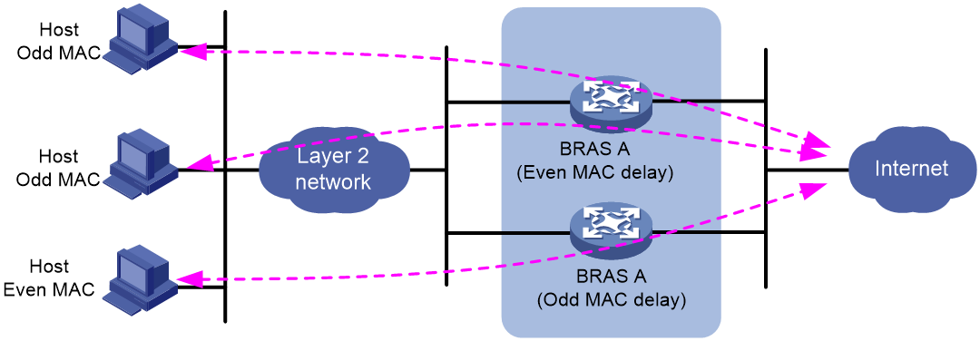
When a BRAS fails (for example, BRAS A fails) as shown in the following figure, users with odd MAC addresses can come online through BRAS B. In this case, BRAS B provides access services for all users to achieve device-level backup.
Figure 42 Schematic diagram (a BRAS fails)
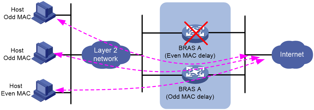
Restrictions and guidelines
This feature takes effect only on PPPoE users and IPoE DHCP users.
For IPoE DHCP users using Web authentication, this feature applies only to users in the pre-authentication domain and has no effect on users in the Web authentication phase.
If you do not specify any keyword in this command, the set response delay applies to all PPPoE users or IPoE DHCP users coming online on the current interface.
If you first execute this command with the even-mac (or odd-mac) keyword specified and then execute this command without specifying any keyword, the latter configuration takes effect, and vice versa.
The public address pool, private address pool, and NAS-IP address must be unique on all BRASs. For example, if NAS-IP address 1.1.1.1 is configured on a BRAS, the NAS-IP address cannot be configured as 1.1.1.1 on any other BRAS.
Examples
# Set the response delay for PPPoE users with even MAC addresses to 10000 milliseconds on Ten-GigabitEthernet3/1/1.
<Sysname> system-view
[Sysname] interface ten-gigabitethernet 3/1/1
[Sysname-Ten-GigabitEthernet3/1/1] pppoe-server access-delay 10000 even-mac
# Set the response delay for IPoE users with even MAC addresses to 10000 milliseconds on Ten-GigabitEthernet3/1/1.
<Sysname> system-view
[Sysname] interface ten-gigabitethernet 3/1/1
[Sysname-Ten-GigabitEthernet3/1/1] ip subscriber access-delay 10000 even-mac
Configuring the traffic permission action
Commands
Use the free account command to permit packets, without rate limiting and accounting.
Applicable scenarios
This feature is applicable in scenarios where you do not want to rate limit or count matching packets.
Usage guidelines
About this task
By default, the BRAS device processes packets as follows:
· For packets matching a QoS policy:
¡ The filter permit and filter deny commands have higher priority than the free account command.
¡ The free account command does not rate limit or count packets.
For example, if you execute both the filter deny and free account commands in traffic behavior web_deny, the device drops matching packets and does not count the dropped packets.
<Sysname> system-view
[Sysname] traffic behavior web_deny
[Sysname-behavior-web_deny] filter deny
[Sysname-behavior-web_deny] free account
· By default, the device drops packets from users that are not online. To permit matching packets without rate limiting and accounting, use the free account command.
For example, if you execute the free account command in traffic behavior web_permit, the BRAS device permits matching packets and does not rate limit or count the permitted packets.
<Sysname> system-view
[Sysname] traffic behavior web_permit
[Sysname-behavior-web_permit] free account
· The BRAS device processes packets from online users according to the configured QoS policy. To permit matching packets without rate limiting and accounting, execute both the filter permit and free account commands in a traffic behavior.
For example, if you execute both the filter permit and free account commands in traffic behavior web_permit, the device permits matching packets and does not rate limit or count the permitted packets.
<Sysname> system-view
[Sysname] traffic behavior web_permit
[Sysname-behavior-web_permit] filter permit
[Sysname-behavior-web_permit] free account
Restrictions and guidelines
For a QoS policy that matches internal traffic in an IPoE network:
· If you do not need to count internal traffic, use the free account command.
· If you need to count internal traffic, do not use the free account command.
Configuration example
In traffic behavior web_permit, permit matching packets without rate limiting and accounting.
<Sysname> system-view
[Sysname] traffic behavior web_permit
[Sysname-behavior-web_permit] free account
Configuring multicast access control
Enabling multicast access control
Commands
(IPv4)
Use igmp authorization-enable to enable the multicast access control feature.
(IPv6)
Use mld authorization-enable to enable the IPv6 multicast access control feature.
Applicable scenarios
Multicast access control.
Usage guidelines
Enable multicast access control on interfaces of the BRAS where you want to control the downstream users' access to multicast traffic.
Examples
(IPv4)
# Enable the multicast access control feature on Ten-GigabitEthernet3/1/1.
<Sysname> system-view
[Sysname] interface ten-gigabitethernet 3/1/1
[Sysname-Ten-GigabitEthernet3/1/1] igmp authorization-enable
(IPv6)
# Enable the IPv6 multicast access control feature on Ten-GigabitEthernet3/1/1.
<Sysname> system-view
[Sysname] interface ten-gigabitethernet 3/1/1
[Sysname-Ten-GigabitEthernet3/1/1] mld authorization-enable
Configuring per-session multicast forwarding
Commands
(IPv4)
Use igmp join-by-session [ mode { both | bras | non-bras } ] to configure per-session multicast forwarding.
(IPv6)
Use mld join-by-session [ mode { both | bras | non-bras } ] to configure per-session IPv6 multicast forwarding.
Applicable scenarios
This feature is applicable to scenarios where the downstream device does not support IGMP snooping and the BRAS must send a separate copy of the multicast data to each receiver.
Usage guidelines
About this task
(IPv4)
By default, the BRAS forwards multicast traffic on a per-interface basis. It sends only one copy of multicast traffic to a downstream interface, and the downstream IGMP snooping device replicates the multicast traffic to each receiver.
If the downstream device does not support IGMP snooping, you can configure the downstream interface on the BRAS to forward multicast traffic on a per-session basis. This allows the BRAS to send a separate copy of the multicast data to each receiver.
(IPv6)
By default, the BRAS forwards the IPv6 multicast traffic on a per-interface basis. It sends one copy of IPv6 multicast traffic to a downstream interface, and the downstream MLD snooping device replicates the IPv6 multicast traffic to each user.
If the downstream device does not support MLD snooping, you can configure the downstream interface on the BRAS to forward IPv6 multicast traffic on a per-session basis. This allows the BRAS to send a separate copy of the IPv6 multicast data to each user.
Restrictions and guidelines
The igmp join-by-session and igmp user-vlan-aggregation commands are mutually exclusive. You cannot configure them on the same device.
The mld join-by-session and mld user-vlan-aggregation commands are mutually exclusive. You cannot configure them on the same device.
Examples
(IPv4)
# Enable per-session multicast forwarding on Ten-GigabitEthernet3/1/1.
<Sysname> system-view
[Sysname] interface ten-gigabitethernet 3/1/1
[Sysname-Ten-GigabitEthernet3/1/1] igmp join-by-session mode bras
(IPv6)
# Enable per-session IPv6 multicast forwarding on Ten-GigabitEthernet3/1/1.
<Sysname> system-view
[Sysname] interface ten-gigabitethernet 3/1/1
[Sysname-Ten-GigabitEthernet3/1/1] mld join-by-session mode bras
Configuring VLAN tagging for multicast packets
Commands
(IPv4)
Use igmp user-vlan-aggregation { dynamic | dot1q vid vlan-id [ second-dot1q vlan-id ] } to configure VLAN tagging for multicast packets.
(IPv6)
Use mld user-vlan-aggregation { dynamic | dot1q vid vlan-id [ second-dot1q vlan-id ] } to configure VLAN tagging for IPv6 multicast packets.
Applicable scenarios
This feature is applicable to the scenario where user packets carry VLAN tags and the downstream device supports IGMP snooping.
Usage guidelines
About this task
(IPv4)
If Dot1q or QinQ VLAN termination is configured on a Layer 3 Ethernet subinterface or Layer 3 aggregate subinterface to terminate VLANs, the BRAS device cannot locate VLANs for multicast receivers.
To resolve this issue, configure VLAN tagging for multicast packets on the BRAS device. This feature enables the BRAS device to tag multicast packets with specific VLAN IDs and send them to IGMP snooping-enabled downstream devices. Then, the downstream devices forward the packets to users in the specified VLANs. This feature also saves the bandwidth on the BRAS device.
The device supports static and dynamic VLAN tagging modes for multicast packets.
· Static VLAN tagging mode—In this mode, you must specify a VLAN ID used to tag multicast packets on an interface. After a multicast user in this VLAN comes online from this interface, the BRAS device tags multicast packets with the VLAN ID and sends the tagged multicast packets to the downstream device. Then, the downstream device forwards the packets to the user in this VLAN.
· Dynamic VLAN tagging mode—In this mode, the BRAS device dynamically tags multicast packets with the IDs of the VLANs to which online multicast users belong. It duplicates multiple copies of multicast packets, tags each copy with a user VLAN ID, and sends the copies to the downstream device. Then, the downstream device forwards each copy to the users in each VLAN.
(IPv6)
If Dot1q or QinQ VLAN termination is configured on a Layer 3 Ethernet subinterface or Layer 3 aggregate subinterface to terminate VLANs, the BRAS device cannot locate VLANs for IPv6 multicast receivers.
To resolve this issue, configure VLAN tagging for IPv6 multicast packets on the BRAS device. This feature enables the BRAS device to tag multicast packets with specific VLAN IDs and send them to MLD snooping-enabled downstream devices. Then, the downstream devices forward the packets to users in the specified VLANs. This feature also saves the bandwidth on the BRAS device.
The device supports static and dynamic VLAN tagging modes for multicast packets.
· Static VLAN tagging mode—In this mode, you must specify a VLAN ID used to tag IPv6 multicast packets on an interface. After a multicast user in this VLAN comes online from this interface, the BRAS device tags IPv6 multicast packets with the VLAN ID and sends the tagged multicast packets to the downstream device. Then, the downstream device forwards the packets to the user in this VLAN.
· Dynamic VLAN tagging mode—In this mode, IPv6 the BRAS device dynamically tags multicast packets with the IDs of the VLANs to which online multicast users belong. It duplicates multiple copies of multicast packets, tags each copy with a user VLAN ID, and sends the copies to the downstream device. Then, the downstream device forwards each copy to the users in each VLAN.
Restrictions and guidelines
(IPv4)
The igmp join-by-session and igmp user-vlan-aggregation commands are mutually exclusive. You cannot configure them on the same device.
The dynamic tagging method is exclusive with the static tagging method for multicast packets. The VLANs specified in the static tagging method must be VLANs allowed by the interface.
· When users of a multicast group are in different VLANs, the device processes a multicast packet of this group as follows:
·In static tagging mode, the device tags the multicast packet with the specified VLAN ID and sends the tagged multicast packet to the downstream device.
· In dynamic tagging mode, the device first duplicates the multicast packet according to the number of VLANs of the multicast users. Then, it tags each multicast packet with a user VLAN ID and sends the tagged multicast packets to the downstream device.
For the configuration or the cancellation to take effect, first log out all online users before you configure dynamic VLAN tagging or cancel the configuration.
This feature does not take effect on PPPoE users.
(IPv6)
The mld join-by-session and mld user-vlan-aggregation commands are mutually exclusive. You cannot configure them on the same device.
The dynamic tagging method is exclusive with the static tagging method for multicast packets. The VLANs specified in the static tagging method must be VLANs allowed by the interface.
· When users of a multicast group are in different VLANs, the device processes a multicast packet of this group as follows:
·In static tagging mode, the device tags the multicast packet with the specified VLAN ID and sends the tagged multicast packet to the downstream device.
· In dynamic tagging mode, the device first duplicates the multicast packet according to the number of VLANs of the multicast users. Then, it tags each multicast packet with a user VLAN ID and sends the tagged multicast packets to the downstream device.
For the configuration or the cancellation to take effect, first log out all online users before you configure dynamic VLAN tagging or cancel the configuration.
This feature does not take effect on PPPoE users.
Examples
(IPv4)
# Configure the multicast packets to be tagged with outer VLAN ID 10 and inner VLAN ID 20 on Ten-GigabitEthernet3/1/1.
<Sysname> system-view
[Sysname] interface ten-gigabitethernet 3/1/1.1
[Sysname-Ten-GigabitEthernet3/1/1.1] vlan-type dot1q vid 10 second-dot1q 1 to 100
[Sysname-Ten-GigabitEthernet3/1/1.1] igmp user-vlan-aggregation dot1q vid 10 second-dot1q 20
# Configure dynamic VLAN tagging for multicast packets on Ten-GigabitEthernet3/1/1.
<Sysname> system-view
[Sysname] interface ten-gigabitethernet 3/1/1.1
[Sysname-Ten-GigabitEthernet3/1/1.1] igmp user-vlan-aggregation dynamic
(IPv6)
# Configure IPv6 multicast packets to be tagged with outer VLAN ID 10 and inner VLAN ID 20 on Ten-GigabitEthernet3/1/1.
<Sysname> system-view
[Sysname] interface ten-gigabitethernet 3/1/1.1
[Sysname-Ten-GigabitEthernet3/1/1.1] vlan-type dot1q vid 10 second-dot1q 1 to 100
[Sysname-Ten-GigabitEthernet3/1/1.1] mld user-vlan-aggregation dot1q vid 10 second-dot1q 20
# Configure dynamic VLAN tagging for IPv6 multicast packets on Ten-GigabitEthernet3/1/1.
<Sysname> system-view
[Sysname] interface ten-gigabitethernet 3/1/1.1
[Sysname-Ten-GigabitEthernet3/1/1.1] mld user-vlan-aggregation dynamic
Configuration examples
Introduction
The following information provides examples for configuring the BRAS feature in service provider applications.
Prerequisites
The configuration examples were created and verified in a lab environment, and all the devices were started with the factory default configuration. When you are working on a live network, make sure you understand the potential impact of every command on your network.
This document assumes that you have basic knowledge of Internet Protocol over Ethernet (IPoE), Point-to-Point Protocol over Ethernet (PPPoE), multicast, Virtual Local Area Network (VLAN) termination, and 802.1Q-in-802.1Q (QinQ).
Example: Configuring the PPPoE server to assign IP addresses to dual-stack users through local DHCP+NDRA+IA_PD
Network configuration
As shown in Figure 43, Router A and Router B are connected through Ethernet interfaces. Router A connects to Router B through PPPoE. Router B acts as a PPPoE server. Configure the PPPoE server as follows:
· IPv4:
Router B acts as a DHCP server to allocate an IPv4 address to Router A.
· IPv6:
¡ Router B uses the NDRA method to allocate an IPv6 address prefix to the WAN interface (Dialer 1 in this example) of Router A. The IPv6 address prefix is from the ND prefix pool.
¡ Router B uses the IA_PD method to allocate a PD prefix to Router A, and Router A allocates an IPv6 address to the attached host through the PD prefix.

Analysis
PPPoE server:
· Create IP address pool pool1, and configure the IP subnet, gateway address, and DNS server address for DHCP clients.
· Create DHCPv6 prefix pool 1 for IPv6 address prefix allocation.
· Create IPv6 address pool ndra, and then apply DHCPv6 prefix pool 1 to the IPv6 address pool. An IPv6 address is allocated to the attached host through the PD prefix.
· In an ISP domain, configure local AAA for users and authorize an IP address pool, ND prefix pool, IPv6 DNS server address, and address pool.
PPPoE client:
· Enable bundle DDR on interface Dialer 1, configure the PPPoE client to operate in permanent mode, and configure the auto-dial timer as 60 seconds for DDR.
· Configure interface Dialer 1 to obtain an IPv4 address through PPP negotiation. Configure interface Dialer 1 to actively request the DNS server IP address from its peer and accept the DNS server IP addresses assigned by the peer.
· Configure interface Dialer 1 to automatically generate an IPv6 global unicast address, which is used for NDRA.
· Configure interface Dialer 1 as a DHCPv6 client and to use DHCPv6 to obtain an IPv6 address and other configuration parameters. After obtaining an IPv6 prefix, the client assigns an ID to the IPv6 prefix used for IA_PD.
· Create IP address pool pool1 to allocate private IPv4 addresses to internal network users.
Procedure
Configuring the RADIUS server
# Configure the RADIUS client IP address as 4.4.4.2 and the shared key as radius.
Add the following contents to the clients.conf file:
client 4.4.4.2/24 {
secret=radius
}
# Configure the user name as user1 and password as 123456TESTplat&!.
Add the following contents to the users file:
user1 Auth-Type == CHAP,User-Password := 123456TESTplat&!
Service-Type = Framed-User,
Framed-Protocol = PPP,
Configuring Router B (PPPoE server)
# Create interface Virtual-Template 1, and enable Virtual-Template 1 to authenticate the peer by using CHAP.
<RouterB> system-view
[RouterB] interface virtual-template 1
[RouterB-Virtual-Template1] ppp authentication-mode chap domain dm1
# Disable RA message suppression.
[RouterB-Virtual-Template1] undo ipv6 nd ra halt
[RouterB-Virtual-Template1] quit
# Enable DHCP.
[RouterB] dhcp enable
# Create IP address pool pool1, and configure the IP subnet, gateway address, and DNS server address for DHCP clients.
[RouterB] ip pool pool1
[RouterB-ip-pool-pool1] network 1.1.1.0 24
[RouterB-ip-pool-pool1] gateway-list 1.1.1.1
[RouterB-ip-pool-pool1] dns-list 8.8.8.8
# Exclude IP address 1.1.1.1 from dynamic allocation.
[RouterB-ip-pool-pool1] forbidden-ip 1.1.1.1
[RouterB-ip-pool-pool1] quit
# Configure Ten-GigabitEthernet 3/1/1 to automatically generate an IPv6 link-local address.
[RouterB] interface ten-gigabitethernet 3/1/1
[RouterB-Ten-GigabitEthernet3/1/1] ipv6 address auto link-local
# Disable RA message suppression.
[RouterB-Ten-GigabitEthernet3/1/1] undo ipv6 nd ra halt
# Enable the DHCPv6 server on Ten-GigabitEthernet 3/1/1.
[RouterB-Ten-GigabitEthernet3/1/1] ipv6 dhcp select server
# Enable the PPPoE server on Ten-GigabitEthernet 3/1/1, and bind it to Virtual-Template 1.
[RouterB-Ten-GigabitEthernet3/1/1] pppoe-server bind virtual-template 1
[RouterB-Ten-GigabitEthernet3/1/1] quit
# (For NDRA.) Configure DHCPv6 prefix pool 1 that contains prefix 10::/32 and specify the assigned prefix length as 64. DHCPv6 prefix pool 1 contains 4294967296 prefixes from 10::/64 to 10:0:FFFF:FFFF::/64.
[RouterB] ipv6 dhcp prefix-pool 1 prefix 10::/32 assign-len 64
# Create IPv6 address pool ndra, and reference prefix pool 1.
[RouterB] ipv6 pool ndra
[RouterB-ipv6-pool-ndra] prefix-pool 1 export-route
[RouterB-ipv6-pool-ndra] quit
# (For IA_PD.) Configure DHCPv6 prefix pool 6 that contains prefix 20::/32 and specify the assigned prefix length as 42.
[RouterB] ipv6 dhcp prefix-pool 6 prefix 20::/32 assign-len 42
# Create IPv6 address pool iapd, and reference prefix pool 6.
[RouterB] ipv6 pool iapd
[RouterB-ipv6-pool-iapd] prefix-pool 6 export-route
[RouterB-ipv6-pool-iapd] quit
# Assign IP address 4.4.4.2/24 to Ten-GigabitEthernet 3/1/2.
[RouterB] interface ten-gigabitethernet 3/1/2
[RouterB-Ten-GigabitEthernet3/1/1] ip address 4.4.4.2 24
[RouterB-Ten-GigabitEthernet3/1/1] quit
# Create a RADIUS scheme named rs1. Configure the primary authentication and accounting servers and specify the authentication key and accounting key.
[RouterB] radius scheme rs1
[RouterB-radius-rs1] primary authentication 4.4.4.1
[RouterB-radius-rs1] primary accounting 4.4.4.1
[RouterB-radius-rs1] key authentication simple radius
[RouterB-radius-rs1] key accounting simple radius
# Exclude the ISP name from the username sent to the RADIUS server.
[RouterB-radius-rs1] user-name-format without-domain
[RouterB-radius-rs1] quit
# Create an ISP domain named dm1 and enter its view. Configure the ISP domain to use RADIUS scheme rs1 for authentication, authorization, and accounting, and authorize an IP address pool, ND prefix pool, IPv6 address of the primary DNS server, and IPv6 address pool to users.
[RouterB] domain name dm1
[RouterB-isp-dm1] authentication ppp radius-scheme rs1
[RouterB-isp-dm1] accounting ppp radius-scheme rs1
[RouterB-isp-dm1] authorization ppp radius-scheme rs1
[RouterB-isp-dm1] authorization-attribute ip-pool pool1
[RouterB-isp-dm1] authorization-attribute ipv6-nd-prefix-pool ndra
[RouterB-isp-dm1] authorization-attribute primary-dns ipv6 8::8
[RouterB-isp-dm1] authorization-attribute ipv6-pool iapd
[RouterB-isp-dm1] quit
Configuring Router A (PPPoE client)
|
|
IMPORTANT: · The device (Router B in this example) can only act as a PPPoE server, and cannot act as a PPPoE client. · The configuration for the device acting as the PPPoE client varies by version. The configuration in this section is for illustration only. For more information, see the manual for the device acting as the PPPoE client. |
# Enable bundle DDR on interface Dialer 1.
<RouterA> system-view
[RouterA] interface dialer 1
[RouterA-Dialer1] dialer bundle enable
# On Dialer 1, configure the CHAP username and password sent from Router A to Router B as user1 and 123456TESTplat&! when Router A is authenticated by Router B by using CHAP.
[RouterA-Dialer1] ppp chap user user1
[RouterA-Dialer1] ppp chap password simple 123456TESTplat&!
# Configure the PPPoE client to operate in permanent mode.
[RouterA-Dialer1] dialer timer idle 0
# Configure the auto-dial timer as 60 seconds for DDR.
[RouterA-Dialer1] dialer timer autodial 60
# (For IPv4.) Configure interface Dialer 1 to obtain an IPv4 address through PPP negotiation. Configure interface Dialer 1 to actively request the DNS server IP address from its peer and accept the DNS server IP addresses assigned by the peer.
[RouterA-Dialer1] ip address ppp-negotiate
[RouterA-Dialer1] ppp ipcp dns request
[RouterA-Dialer1] ppp ipcp dns admit-any
# (For IPv4.) Translate the source addresses of the packets from internal hosts into the IP address of interface Dialer 1.
[RouterA-Dialer1] nat outbound
# (For NDRA.) Configure interface Dialer 1 to automatically generate an IPv6 global unicast address.
[RouterA-Dialer1] ipv6 address auto
# (For IA_PD.) Configure interface Dialer 1 to use DHCPv6 to obtain an IPv6 address and other configuration parameters.
[RouterA-Dialer1] ipv6 address dhcp-alloc
# (For IA_PD.) Configure interface Dialer 1 as a DHCPv6 client for IPv6 prefix acquisition. Configure the DHCPv6 client to assign ID 1 to the obtained IPv6 prefix.
[RouterA-Dialer1] ipv6 dhcp client pd 1
[RouterA-Dialer1] quit
# Configure a PPPoE session and specify dialer bundle 1 (which corresponds to interface Dialer 1) for the session.
[RouterA] interface ten-gigabitethernet 3/1/2
[RouterA-Ten-GigabitEthernet3/1/2] pppoe-client dial-bundle-number 1
[RouterA-Ten-GigabitEthernet3/1/2] quit
# Configure the default route.
[RouterA] ip route-static 0.0.0.0 0 dialer 1
[RouterA] ipv6 route-static :: 0 dialer 1
# Enable DHCP.
[RouterA] dhcp enable
# Configure DHCP address pool pool1 to allocate private IPv4 addresses to internal network users.
[RouterA]ip-pool pool1
[RouterA-dhcp-pool-pool1] network 192.168.1.0 24
[RouterA-dhcp-pool-pool1] gateway-list 192.168.1.1
[RouterA-dhcp-pool-pool1] dns-list 8.8.8.8
# Exclude IP address 192.168.1.1 from dynamic allocation.
[RouterA-dhcp-pool-pool1] forbidden-ip 192.168.1.1
[RouterA-dhcp-pool-pool1] quit
# Assign the IPv4 gateway address of internal network users to Ten-GigabitEthernet 3/1/1.
[RouterA] interface ten-gigabitethernet 3/1/1
[RouterA-Ten-GigabitEthernet3/1/1] ip address 192.168.1.1 24
# Disable RA message suppression on Ten-GigabitEthernet 3/1/1.
[RouterA-Ten-GigabitEthernet3/1/1] undo ipv6 nd ra halt
# Configure Ten-GigabitEthernet 3/1/1 to dynamically obtain IPv6 prefix 1 (use IPv6 prefix 1 to generate IPv6 address 20::123:1:1, which must be configured as the gateway address for the user attached to Router A) and advertise IPv6 prefix 1 to endpoints through RA messages.
[RouterA-Ten-GigabitEthernet3/1/1] ipv6 address 1 123::123:1:1/64
[RouterA-Ten-GigabitEthernet3/1/1] quit
Verifying the configuration
After the configuration is completed, Router A uses username user1 and password 123456TESTplat&! to access Router B through PPPoE. Then, Router B obtains an IPv4 address through DHCPv4, and uses the assigned IPv6 prefix and the IPv6 interface ID obtained through IPv6CP negotiation to automatically generate an IPv6 global unicast address.
[RouterB] display access-user interface ten-gigabitethernet 3/1/1
UserID Interface IP address MAC address S-/C-VLAN
Username Access type
IPv6 address
0x6 XGE3/1/1 1.1.1.2 001b-21a8-0949 -/-
user1 PPPoE
10::F85B:7EE1:1410:74C9
The output shows that Router B assigns a PD prefix to Router A through DHCPv6.
# Display binding information for the assigned IPv6 prefixes.
[RouterB] display ipv6 dhcp server pd-in-use
Pool: iapd
IPv6 prefix Type Lease expiration
20::/42 Auto(C) Jul 10 19:45:01 2019
Pool: ndra
IPv6 prefix Type Lease expiration
10::/64 Auto(C) Expires after 2100
The output shows that Router B assigns a PD prefix to Router A through DHCPv6.
# Display information about IPv6 prefixes created on Router A.
[RouterA] display ipv6 prefix
Number Prefix Type
1 20::/42 Dynamic
The output shows that after Router A obtains a PD prefix from Router B, Router A creates an IPv6 prefix with ID 1 according to the ipv6 dhcp client pd 1 command.
Then, Router A can assign prefix 20::/42 to the host who uses the prefix to generate an IPv6 global unicast address.
Configuration files
· Router A (PPPoE client):
#
sysname RouterA
#
dhcp enable
#
ip pool pool1
gateway-list 192.168.1.1
network 192.168.1.0 mask 255.255.255.0
dns-list 8.8.8.8
forbidden-ip 192.168.1.1
#
interface Dialer1
ppp chap password cipher $c$3$cl/gf2/X3k2tjzq5jlCEDnRu0u07xpk4WMEmXkhrEw4edO8=
ppp chap user user1
ppp ipcp dns admit-any
ppp ipcp dns request
dialer bundle enable
dialer timer idle 0
dialer timer autodial 60
ip address ppp-negotiate
nat outbound
ipv6 address auto
ipv6 address dhcp-alloc
ipv6 dhcp client pd 1
#
interface Ten-GigabitEthernet3/1/1
port link-mode route
combo enable copper
ip address 192.168.1.1 255.255.255.0
ipv6 address 1 123::123:1:1/64
undo ipv6 nd ra halt
#
interface Ten-GigabitEthernet3/1/2
port link-mode route
combo enable copper
pppoe-client dial-bundle-number 1
#
ip route-static 0.0.0.0 0 Dialer1
ipv6 route-static :: 0 Dialer1
#
· Router B (PPPoE server):
#
sysname RouterB
#
dhcp enable
#
ipv6 dhcp prefix-pool 1 prefix 10::/32 assign-len 64
ipv6 dhcp prefix-pool 6 prefix 20::/32 assign-len 42
#
ip pool pool1
gateway-list 1.1.1.1
network 1.1.1.0 mask 255.255.255.0
dns-list 8.8.8.8
forbidden-ip 1.1.1.1
#
ipv6 pool iapd
prefix-pool 6 export-route
#
ipv6 pool ndra
prefix-pool 1 export-route
#
interface Virtual-Template1
ppp authentication-mode chap domain dm1
#
interface Ten-GigabitEthernet3/1/1
port link-mode route
combo enable copper
ipv6 dhcp select server
ipv6 address auto link-local
undo ipv6 nd ra halt
pppoe-server bind virtual-template 1
#
interface Ten-GigabitEthernet3/1/2
port link-mode route
combo enable copper
ip address 4.4.4.2 mask 255.255.255.0
#
radius scheme rs1
primary authentication 4.4.4.1
primary accounting 4.4.4.1
key authentication cipher $c$3$Op8/zHukkwxWVrqrnhlG4cX2ENppi8Flrg==
key accounting cipher $c$3$D43K/vF4D75aBIayM49pAqY2nNetyXbfmQ==
user-name-format without-domain
#
domain name dm1
authorization-attribute ip-pool pool1
authorization-attribute ipv6-pool iapd
authorization-attribute ipv6-nd-prefix-pool ndra
authorization-attribute primary-dns ipv6 8::8
authentication ppp radius-scheme rs1
authorization ppp radius-scheme rs1
accounting ppp radius-scheme rs1
#
Configuring broadband dual-stack user services (PPPoE-NAT collaboration+prefix assignment by ND prefix pool)
The broadband service is a basic service of a service provider MAN. Broadband users use the PPPoE single-stack or dual-stack method to access. The BRAS performs service control, and the AAA server performs authentication, authorization, and accounting. Additionally, the BRAS provides the green channel (also called rainbow channel) feature. This feature performs access control and URL redirection for defaulting users and redirects the defaulting users to the L2TP green channel.
Network configuration
As shown in Figure 44, Router A acts as a BRAS, and provides access services for broadband users. The network requirements are as follows:
· Overall:
¡ Broadband user Host A accesses the BRAS in PPPoE mode through a Layer 2 network.
¡ The BRAS acts as a DHCP server to allocate an IPv4 address to the user.
¡ The BRAS acts as a PPPoE server to allocate an IPv6 address to Host A through ND. In this scenario, Host A obtains an IPv6 address prefix through the ND RA packets, and obtains an IPv6 interface ID through IPv6CP negotiation. An IPv6 global unicast address is generated based on the IPv6 address prefix and IPv6 interface ID. The IPv6 address prefix in the RA packets is obtained from the ND prefix pool.
¡ NAT collaborates with the BRAS. When a broadband user passes authentication and is assigned a private IPv4 address, a public address and port block are assigned to the user. NAT is not performed for IPv6 addresses.
¡ When the charge of the user is overdue, the AAA server pushes the payment page to the defaulting user through COA messages. The push period is set to permanent.
¡ The Srun software is deployed on the server to manage authentication and accounting.
· AAA:
¡ Two RADIUS servers are deployed, one primary and one secondary.
¡ Interface LoopBack0 is used as the source interface for sending RADIUS packets on the BRAS.
¡ The function of interpreting the RADIUS class attribute (attribute 25) as CAR parameters is enabled.
¡ A user that encounters accounting-start failures stays online.
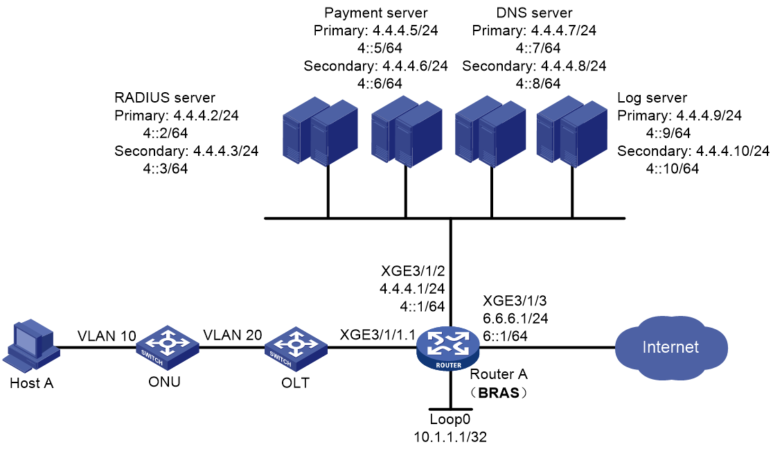
Analysis
· In the local domain, bind load balancing user groups to a NAT instance. In this way, a user can carry the user group attribute after successfully passing authentication and coming online. The AAA server does not need to separately assign user group attributes.
· Create user groups, and assign the same user group attribute to users in the same domain. Then, an ACL can recognize traffic by user group name and then the traffic can be redirected to a NAT instance.
· In an ISP domain, you must configure the user address type as private IPv4 address to trigger NAT-BRAS collaboration.
· In the environment where a CGN module is used to provide the NAT feature, for dynamic NAT or port block-based NAT, you must bind a NAT address group to a backup group with the CGN module.
· (Optional.) The green channel service opens the payment page to prompt a defaulting user to pay when the charge of the user is overdue. This feature can be implemented in one of the following two methods.
¡ Configure the device as a DAE server. The RADIUS server acts as a DAE client. COA messages are used to implement the green channel feature.
¡ Assign a new authentication domain on the RADIUS server. The new authentication domain is used to trigger L2TP tunnel setup to implement the green channel feature.
This example uses the first method. When the first method is used, you can configure the number of redirect times and effective time in the domain. The RADIUS server must assign the following attributes:
¡ User-Name (attribute 1)—Identifies a user.
¡ Framed-IP-Address (attribute 8)—User IP address.
¡ Web-URL (private attribute 250)—Web redirect URL of a user, which is used together with attribute 246.
¡ Auth-Detail-Result (private attribute 246)—User authentication result details. Possible values include:
- 0—Normal user. In this case, the server will cancel assigning attribute 250 and allow the user to access any network resources.
- 1—Defaulting user. In this case, the server will assign attribute 250 and allow the user to access network resources on the URL allowlist. If the user accesses the other network resources, the requests will be redirected to the URL defined in attribute 250.
· For a defaulting user to access the payment page, you can configure an object group-based URL allowlist and add the DNS server address and payment page address (http://4.4.4.5/xxx in this example) to the URL allowlist.
· To facilitate QoS policy-based control for users, assign users to different user groups based on their states:
¡ Defaulting users—Defaulting users need access control. Assign these users to the user group named qianfei.
¡ Normal users—These users do not need access control. Assign these users to the user group named normal.
· For users in user group qianfei and user group normal, perform the following QoS policy-based controls separately:
¡ Users in user group qianfei
- Allow them to access the payment page.
- When a user accesses an address other than the payment page address through HTTP or HTTPS, all requests are redirected to the payment page (http://4.4.4.5/xxx in this example), and the other traffic is dropped.
¡ Users in user group normal
- Allow them to access any destination address.
- When a user accesses any destination address, IPv4 traffic is redirected to the CGN module for NAT. IPv6 traffic is directly forwarded without NAT processing.
· When the charge of a user is overdue, the AAA server sends COA messages to change the user group of the defaulting user from user group normal to user group qianfei. After the user pays successfully, the AAA server sends COA messages to change the user group of the user from user group qianfei to user group normal. In the NAT collaboration scenario, COA messages cannot be directly used to change the user group attribute of users in the current software version. In this example, a new ISP domain is assigned to users and user group qianfei is bound to a NAT instance in the new ISP domain to indirectly change the user group attribute of users.
· (Optional.) On the access interface of users, configure NAS-Port-ID binding for PPPoE users, so that users always use the same interface information to fill in the NAS-Port-ID attribute.
· Use the AAA server to assign the user accounting and rate-limiting policies.
Procedure
Configuring IP addresses and routes
# Assign IPv4 address 4.4.4.1/24 and IPv6 address 4::1/64 to Ten-GigabitEthernet 3/1/2 on the BRAS.
<BRAS> system-view
[BRAS] interface ten-gigabitethernet 3/1/2
[BRAS-Ten-GigabitEthernet3/1/2] ip address 4.4.4.1 24
[BRAS-Ten-GigabitEthernet3/1/2] ipv6 address 4::1 64
[BRAS-Ten-GigabitEthernet3/1/2] quit
# Assign IPv4 address 6.6.6.1/24 and IPv6 address 6::1/64 to Ten-GigabitEthernet 3/1/3 on the BRAS.
[BRAS] interface ten-gigabitethernet 3/1/3
[BRAS-Ten-GigabitEthernet3/1/3] ip address 6.6.6.1 24
[BRAS-Ten-GigabitEthernet3/1/3] ipv6 address 6::1 64
[BRAS-Ten-GigabitEthernet3/1/3] quit
# Configure default routes to the Internet.
[BRAS] ip route-static 0.0.0.0 0 6.1.1.2
[BRAS] ipv6 route-static :: 0 6::2
Configuring the DNS servers
In this example, Windows Server 2016 is used to describe the basic DNS server configuration. The configurations for the primary and secondary DNS servers are similar. This section uses the primary DNS server as an example. For information about configuring the log servers, see the corresponding software descriptions.
To configure a DNS server:
1. Install the DNS component:
a. Log in to the server, click Windows, and select Server Manager.
b. Click Add Roles and Features, and configure DNS.
c. On the Before you begin page, click Next.
d. On the Select installation type page, use the default option (Role-based or feature-based installation), and click Next.
e. On the Select destination server page, use the default option (Select a server from the server pool), and click Next.
f. On the Select server roles page, select DNS Server. On the Add Roles and Features Wizard page that opens, click Add Features, and then click Next.
g. On the Select features page, use the default settings, and click Next.
h. On the DNS Server page, click Next.
i. Click Install on the Confirm installation selections page and wait for the installation to complete.
j. Once installation completes, click Close to complete the installation of the DNS component.
2. Create an IPv4 forward lookup zone:
a. On the Server Manager page, click Tools, and select DNS.
b. Right-click Forward Lookup Zones on the DNS Manager page and select New Zone.
c. On the New Zone Wizard page, click Next.
d. On the Zone Type page, select Primary zone, and click Next.
e. On the Zone Name page, enter zone name ipv4.test.com.
f. On the Zone File page, use the default settings and click Next.
g. On the Dynamic Update page, select Do not allow dynamic updates and click Next.
h. On the New Zone Wizard page, click Finish.
i. On the DNS Manager page, click Forward Lookup Zones, right-click ipv4.test.com, and click New Host.
j. On the New Host page, enter host name www, enter IP address 4.4.4.7, and click Add Host.
The IPv4 forward lookup zone has been successfully created.
3. Create an IPv4 reverse lookup zone:
a. Right-click Reverse Lookup Zones on the DNS Manager page and select New Zone.
b. On the New Zone Wizard page, click Next.
c. On the Zone Type page, select Primary zone, and click Next.
d. On the Reverse Lookup Zone Name page, select IPv4 Reverse Lookup Zone, and click Next.
e. On the Reverse Lookup Zone Name page, enter network ID 4.4.4, and click Next.
f. On the Zone File page, use the default settings and click Next.
g. On the Dynamic Update page, select Do not allow dynamic updates and click Next.
h. On the New Zone Wizard page, click Finish.
i. On the DNS Manager page, click Reverse Lookup Zones, right-click 4.4.4.in-addr.arpa.dns, and click New Pointer.
j. On the New Resource Record page, enter host IP address 4.4.4.7, enter host name www.ipv4.test.com, and click OK.
The IPv4 reverse lookup zone has been successfully created.
4. Create an IPv6 forward lookup zone:
a. On the Server Manager page, click Tools, and select DNS.
b. Right-click Forward Lookup Zones on the DNS Manager page and select New Zone.
c. On the New Zone Wizard page, click Next.
d. On the Zone Type page, select Primary zone, and click Next.
e. On the Zone Name page, enter zone name ipv6.test.com.
f. On the Zone File page, use the default settings and click Next.
g. On the Dynamic Update page, select Do not allow dynamic updates and click Next.
h. On the New Zone Wizard page, click Finish.
i. On the DNS Manager page, click Forward Lookup Zones, right-click ipv6.test.com, and click New Host.
j. On the New Host page, enter host name www, enter IP address 4::7, and click Add Host.
The IPv6 forward lookup zone has been successfully created.
5. Create an IPv6 reverse lookup zone:
a. Right-click Reverse Lookup Zones on the DNS Manager page and select New Zone.
b. On the New Zone Wizard page, click Next.
c. On the Zone Type page, select Primary zone, and click Next.
d. On the Reverse Lookup Zone Name page, select IPv6 Reverse Lookup Zone, and click Next.
e. On the Reverse Lookup Zone Name page, enter network ID 4000:0000:0000:0000::/64, and click Next.
f. On the Zone File page, use the default settings and click Next.
g. On the Dynamic Update page, select Do not allow dynamic updates and click Next.
h. On the New Zone Wizard page, click Finish.
i. On the DNS Manager page, click Reverse Lookup Zones, right-click 0.0.0.0.0.0.0.0.0.0.0.0.0.0.0.4.in-addr.arpa.dns, and click New Pointer.
j. On the New Resource Record page, enter host IP address 4000.0000.0000.0000.0000.0000.0000.0007, enter host name www.ipv6.test.com, and click OK.
The IPv6 reverse lookup zone has been successfully created.
Configuring the BRAS
1. Configure DHCP.
# Enable DHCP.
[BRAS] dhcp enable
# Create local BAS IP address pool pool1.
[BRAS] ip pool pool1 bas local
[BRAS-ip-pool-pool1] gateway 3.3.3.1 24
[BRAS-ip-pool-pool1] dns-list 4.4.4.7 4.4.4.8
# Exclude 3.3.3.1 from dynamic address allocation.
[BRAS-ip-pool-pool1] forbidden-ip 3.3.3.1
[BRAS-ip-pool-pool1] quit
# Create DHCPv6 prefix pool 1, specify prefix range 2003::/48 for prefix pool 1, and set the prefix length used for dynamic allocation to 64.
[BRAS] ipv6 dhcp prefix-pool 1 prefix 2003::/48 assign-len 64
# Create IPv6 address pool ndra, and then apply DHCPv6 prefix pool 1 to the IPv6 address pool.
[BRAS] ipv6 pool ndra
[BRAS-ipv6-pool-ndra] prefix-pool 1 export-route
[BRAS-ipv6-pool-ndra] quit
# Enable automatic link-local address generation on Ten-GigabitEthernet3/1/1.1.
[BRAS] interface ten-gigabitethernet 3/1/1.1
[BRAS-Ten-GigabitEthernet3/1/1.1] ipv6 address auto link-local
# Disable RA message advertisement suppression on Ten-GigabitEthernet3/1/1.1.
[BRAS-Ten-GigabitEthernet3/1/1.1] undo ipv6 nd ra halt
# Enable Ten-GigabitEthernet3/1/1.1 to operate in DHCPv6 server mode.
[BRAS-Ten-GigabitEthernet3/1/1.1] ipv6 dhcp select server
[BRAS-Ten-GigabitEthernet3/1/1.1] quit
2. Configure global NAT.
a. Configure bindings between CGN cards and a failover group.
# Create failover group failgrp and enter its view.
[BRAS] failover group failgrp id 1
b. # Bind CGN cards to failover group failgrp: Configure slot 5 as the primary node and slot 6 as the secondary node.
[BRAS-failover-group-failgrp] bind slot 5 primary//If the specified slot supports CPU, you must specify the CPU parameter following the slot parameter.
[BRAS-failover-group-failgrp] bind slot 6 secondary
[BRAS-failover-group-failgrp] quit
c. Configure a service instance group.
# Create service instance group sgrp and enter its view.
[BRAS] service-instance-group sgrp
# Associate service instance group sgrp with failover group failgrp.
[BRAS-service-instance-group-sgrp] failover-group failgrp
[BRAS-service-instance-group-sgrp] quit
d. Configure an advanced ACL.
# Create advanced IPv4 ACL 3000.
[BRAS] acl advanced 3000
# Configure a rule for advanced IPv4 ACL 3000 to permit only packets from internal subnet 3.3.3.0/24. This ensures that IP address translation is available only for packets from users in internal subnet 3.3.3.0/24.
[BRAS-acl-ipv4-adv-3000] rule permit ip source 3.3.3.0 0.0.0.255
[BRAS-acl-ipv4-adv-3000] quit
e. Configure global NAT.
# Create address group 1. Add public address range 6.6.6.2 to 6.6.6.255, set the port block size to 256, the number of extended port blocks to 3, and the number of ports in an extended port block to 1024.
[BRAS] nat address-group 1
[BRAS-address-group-1] address 6.6.6.2 6.6.6.255
[BRAS-address-group-1] port-range 1024 65535
[BRAS-address-group-1] port-block block-size 256 extended-block-number 3 extended-block-size 1024
# Create NAT instance inst.
[BRAS] nat instance inst id 1
# Associate service instance group sgrp with the NAT instance.
[BRAS-nat-instance-inst] service-instance-group sgrp
# Configure an outbound NAT rule for NAT instance inst. Use address group 1 to translate packets permitted by ACL 3000.
[BRAS-nat-instance-inst] nat outbound 3000 address-group 1
[BRAS-nat-instance-inst] quit
f. Configure the three-tuple mode. The three-tuple includes source IP address, source port number, and protocol type.
# Configure the Endpoint-Independent Mapping mode for TCP and UDP packets and create EIM entries for TCP and UDP connections.
[BRAS] nat mapping-behavior endpoint-independent tcp udp
g. Enable NAT ALG.
|
|
NOTE: This example only introduces how to enable NAT ALG for FTP and PPTP. You can enable ALG for other protocols as needed. For more information, see the NAT configuration book. |
# Enable NAT ALG for FTP and PPTP.
[BRAS] nat alg ftp (Default setting)
[BRAS] nat alg pptp
h. Configure NAT logging.
|
|
NOTE: Log export consumes system resources. To avoid overconsumption of system resources, this example only introduces how to configure basic NAT logging. You can enable logging for other events as needed. For more information, see the NAT configuration book. |
# Enable NAT logging.
[BRAS] nat log enable
# Enable logging for port usage in port blocks and set the usage threshold to 90%.
[BRAS] nat log port-block port-usage threshold 90
# Enable NAT444 user logging for port block assignment events.
[BRAS] nat log port-block-assign
# Enable NAT444 user logging for port block withdrawal events.
[BRAS] nat log port-block-withdraw
# Enable fast log output.
[BRAS] customlog format cmcc
# Configure the timestamp of fast output logs to show the system time.
[BRAS] customlog timestamp localtime
# Specify the IP address of Loopback 0 as the source IP address for fast log output.
[BRAS] interface loopback 0
[BRAS-LoopBack0] ip address 10.1.1.1 32
[BRAS-LoopBack0] quit
[BRAS] customlog host source loopback0
# Output NAT session logs and NAT444 user logs in cmcc format to log hosts 4.4.4.9 and 4.4.4.10.
[BRAS] customlog host 4.4.4.9 port 1000 export cmcc-sessionlog cmcc-userlog sysname logserver01
[BRAS] customlog host 4.4.4.10 port 1000 export cmcc-sessionlog cmcc-userlog sysname logserver02
3. Create user groups.
# Create a user group named qianfei.
[BRAS] user-group qianfei
New user group added.
[BRAS-ugroup-qianfei] quit
# Create a user group named normal.
[BRAS] user-group normal
New user group added.
[BRAS-ugroup-normal] quit
4. Configure IP address object groups to match the payment servers and DNS servers.
# Create an IPv4 address object group named freeurl_ipv4, and configure IPv4 address objects to match the payment servers and DNS servers. This object group can be considered as a URL allowlist. The BRAS will not exchange packets with users after communicating with the RADIUS server and log server, so they do not need to be added to the allowlist.
[BRAS] object-group ip address freeurl_ipv4
[BRAS-obj-grp-ip-freeurl_ipv4] network host address 4.4.4.5 //Primary payment server
[BRAS-obj-grp-ip-freeurl_ipv4] network host address 4.4.4.6 //Backup payment server
[BRAS-obj-grp-ip-freeurl_ipv4] network host address 4.4.4.7 //Primary DNS server
[BRAS-obj-grp-ip-freeurl_ipv4] network host address 4.4.4.8 //Backup DNS server
[BRAS-obj-grp-ip-freeurl_ipv4] quit
# Create an IPv6 address object group named freeurl_ipv6, and configure IPv6 address objects to match the payment servers and DNS servers.
[BRAS] object-group ipv6 address freeurl_ipv6
[BRAS-obj-grp-ipv6-freeurl_ipv6] network host address 4::5 //Primary payment server
[BRAS-obj-grp-ipv6-freeurl_ipv6] network host address 4::6 //Backup payment server
[BRAS-obj-grp-ipv6-freeurl_ipv6] network host address 4::7 //Primary DNS server
[BRAS-obj-grp-ipv6-freeurl_ipv6] network host address 4::8 //Backup DNS server
[BRAS-obj-grp-ipv6-freeurl_ipv6] quit
5. Configure QoS policies.
a. Configure ACLs to match packets matching the IP address object groups.
# Configure an IPv4 advanced ACL named qianfei_in to match the packets from a user in user group qianfei to an IPv4 address in the IPv4 address object group freeurl_ipv4. Configure an IPv6 advanced ACL named qianfei_in to match the packets from a user in user group qianfei to an IPv6 address in the IPv6 address object group freeurl_ipv6.
[BRAS] acl advanced name qianfei_in
[BRAS-acl-ipv4-adv-qianfei_in] rule 0 permit ip destination object-group freeurl_ipv4 user-group qianfei
[BRAS-acl-ipv4-adv-qianfei_in] quit
[BRAS] acl ipv6 advanced name qianfei_in
[BRAS-acl-ipv6-adv-qianfei_in] rule 0 permit ipv6 destination object-group freeurl_ipv6 user-group qianfei
[BRAS-acl-ipv6-adv-qianfei_in] quit
# Configure an IPv4 advanced ACL named qianfei_out to match the packets from an IPv4 address in the IPv4 address object group freeurl_ipv4 to a user in the user group qianfei. Configure an IPv6 advanced ACL named qianfei_out to match the packets from an IPv6 address in the IPv6 address object group freeurl_ipv6 to a user in the user group qianfei.
[BRAS] acl advanced name qianfei_out
[BRAS-acl-ipv4-adv-qianfei_out] rule 0 permit ip source object-group freeurl_ipv4 user-group qianfei
[BRAS-acl-ipv4-adv-qianfei_out] quit
[BRAS] acl ipv6 advanced name qianfei_out
[BRAS-acl-ipv6-adv-qianfei_out] rule 0 permit ipv6 source object-group freeurl_ipv6 user-group qianfei
[BRAS-acl-ipv6-adv-qianfei_out] quit
# Configure an IPv4 advanced ACL named qianfei_ip to match all IPv4 packets from and to a user in user group qianfei. Configure an IPv6 advanced ACL named qianfei_ip to match all IPv6 packets from and to a user in user group qianfei.
[BRAS] acl advanced name qianfei_ip
[BRAS-acl-ipv4-adv-qianfei_ip] rule 0 permit ip user-group qianfei
[BRAS-acl-ipv4-adv-qianfei_ip] quit
[BRAS] acl ipv6 advanced name qianfei_ip
[BRAS-acl-ipv6-adv-qianfei_ip] rule 0 permit ipv6 user-group qianfei
[BRAS-acl-ipv6-adv-qianfei_ip] quit
# Configure an IPv4 advanced ACL named normal_ip to match all IPv4 packets from and to a user in user group normal. Configure an IPv6 advanced ACL named normal_ip to match all IPv6 packets from and to a user in user group normal.
[BRAS] acl advanced name normal_ip
[BRAS-acl-ipv4-adv-normal_ip] rule 0 permit ip user-group normal
[BRAS-acl-ipv4-adv-normal_ip] quit
[BRAS] acl ipv6 advanced name normal_ip
[BRAS-acl-ipv6-adv-normal_ip] rule 0 permit ipv6 user-group normal
[BRAS-acl-ipv6-adv-normal_ip] quit
b. Configure traffic classes:
# Create a traffic class named qianfei_in_ipv4, and use IPv4 advanced ACL qianfei_in in the traffic class.
[BRAS] traffic classifier qianfei_in_ipv4 operator or
[BRAS-classifier-qianfei_in_ipv4] if-match acl name qianfei_in
[BRAS-classifier-qianfei_in_ipv4] quit
# Create a traffic class named qianfei_in_ipv6, and use IPv6 advanced ACL qianfei_in in the traffic class.
[BRAS] traffic classifier qianfei_in_ipv6 operator or
[BRAS-classifier-qianfei_in_ipv6] if-match acl ipv6 name qianfei_in
[BRAS-classifier-qianfei_in_ipv6] quit
# Create a traffic class named qianfei_out, and use IPv4 advanced ACL qianfei_out and IPv6 advanced ACL qianfei_out in the traffic class.
[BRAS] traffic classifier qianfei_out operator or
[BRAS-classifier-qianfei_out] if-match acl name qianfei_out
[BRAS-classifier-qianfei_out] if-match acl ipv6 name qianfei_out
[BRAS-classifier-qianfei_out] quit
# Create a traffic class named qianfei_ip_deny, and use IPv4 advanced ACL qianfei_ip and IPv6 advanced ACL qianfei_ip in the traffic class.
[BRAS] traffic classifier qianfei_ip_deny operator or
[BRAS-classifier-qianfei_ip_deny] if-match acl name qianfei_ip
[BRAS-classifier-qianfei_ip_deny] if-match acl ipv6 name qianfei_ip
[BRAS-classifier-qianfei_ip_deny] quit
# Create a traffic class named normal_in_ipv4, and use IPv4 advanced ACL normal_ip in the traffic class.
[BRAS] traffic classifier normal_in_ipv4 operator or
[BRAS-classifier-normal_in_ipv4] if-match acl name normal_ip
[BRAS-classifier-normal_in_ipv4] quit
# Create a traffic class named normal_in_ipv6, and use IPv4 advanced ACL normal_ip in the traffic class.
[BRAS] traffic classifier normal_in_ipv6 operator or
[BRAS-classifier-normal_in_ipv6] if-match acl ipv6 name normal_ip
[BRAS-classifier-normal_in_ipv6] quit
# Create a traffic class named normal_out_ipv4 and use IPv4 advanced ACL normal_ip in the traffic class.
[BRAS] traffic classifier normal_out_ipv4 operator or
[BRAS-classifier-normal_out_ipv4] if-match acl name normal_ip
[BRAS-classifier-normal_out_ipv4] quit
# Create a traffic class named normal_out_ipv6 and use IPv6 advanced ACL normal_ip in the traffic class.
[BRAS] traffic classifier normal_out_ipv6 operator or
[BRAS-classifier-normal_out_ipv6] if-match acl ipv6 name normal_ip
[BRAS-classifier-normal_out_ipv6] quit
c. Configure traffic behaviors:
# Create a traffic behavior named qianfei_in_ipv4, and configure an action of redirecting the following IPv4 packets to the CGN card for NAT processing:
- IPv4 packets from a user in user group qianfei to the payment server.
- IPv4 packets from a user in user group qianfei to the DNS server.
[BRAS] traffic behavior qianfei_in_ipv4
[BRAS-behavior-qianfei_in_ipv4] bind nat-instance inst
[BRAS-behavior-qianfei_in_ipv4] free account
[BRAS-behavior-qianfei_in_ipv4] quit
# Create a traffic behavior named qianfei_in_ipv6, and configure an action of permitting the following IPv6 packets without NAT processing:
- IPv6 packets from a user in user group qianfei to the payment server.
- IPv6 packets from a user in user group qianfei to the DNS server.
[BRAS] traffic behavior qianfei_in_ipv6
[BRAS-behavior-qianfei_in_ipv6] filter permit
[BRAS-behavior-qianfei_in_ipv6] free account
[BRAS-behavior-qianfei_in_ipv4] quit
# Create a traffic behavior named qianfei_out, and configure an action of permitting the IPv4 packets and IPv6 packets from the payment server and the DNS server to a user in the user group qianfei.
[BRAS] traffic behavior qianfei_out
[BRAS-behavior-qianfei_out] filter permit
[BRAS-behavior-qianfei_out] free account
[BRAS-behavior-qianfei_out] quit
# Create a traffic behavior named qianfei_ip_deny, and configure an action of denying all IPv4 packets and IPv6 packets from and to a user in user group qianfei.
[BRAS] traffic behavior qianfei_ip_deny
[BRAS-behavior-qianfei_ip_deny] filter deny
[BRAS-behavior-qianfei_ip_deny] free account
[BRAS-behavior-qianfei_ip_deny] quit
# Create a traffic behavior named normal_in_ipv4, and configure an action of redirecting all IPv4 packets from and to a user in user group normal to the CGN card for NAT processing.
[BRAS] traffic behavior normal_in_ipv4
[BRAS-behavior-normal_in_ipv4] bind nat-instance inst
[BRAS-behavior-normal_in_ipv4] quit
# Create a traffic behavior named normal_in_ipv6, and configure an action of permitting all IPv6 packets from and to a user in user group normal without NAT processing.
[BRAS] traffic behavior normal_in_ipv6
[BRAS-behavior-normal_in_ipv6] filter permit
[BRAS-behavior-normal_in_ipv6] quit
# Create a traffic behavior named normal_out_ipv4, and configure an action of permitting all IPv4 packets from and to a user in user group normal without NAT processing.
[BRAS] traffic behavior normal_out_ipv4
[BRAS-behavior-normal_out_ipv4] filter permit
[BRAS-behavior-normal_out_ipv4] quit
# Create a traffic behavior named normal_out_ipv6, and configure an action of permitting all IPv6 packets from and to a user in user group normal without NAT processing.
[BRAS] traffic behavior normal_out_ipv6
[BRAS-behavior-normal_out_ipv6] filter permit
[BRAS-behavior-normal_out_ipv6] quit
d. Configure QoS policies:
# Create a QoS policy named in, which is to be applied to the inbound direction.
[BRAS] qos policy in
# Associate traffic classes with traffic behaviors.
For user group qianfei:
- Redirect IPv4 packets from a user in user group qianfei to the payment server and the DNS server to the CGN card for NAT processing.
- Permit the IPv6 packets from a user in user group qianfei to the payment server and the DNS server without NAT processing.
- Deny all other IPv4 and IPv6 packets.
For user group normal:
- Redirect all IPv4 packets to the CGN card for NAT processing.
- Permit all IPv6 packets without NAT processing.
[BRAS-qospolicy-in] classifier qianfei_in_ipv4 behavior qianfei_in_ipv4
[BRAS-qospolicy-in] classifier qianfei_in_ipv6 behavior qianfei_in_ipv6
[BRAS-qospolicy-in] classifier qianfei_ip_deny behavior qianfei_ip_deny
[BRAS-qospolicy-in] classifier normal_in_ipv4 behavior normal_in_ipv4
[BRAS-qospolicy-in] classifier normal_in_ipv6 behavior normal_in_ipv6
[BRAS-qospolicy-in] quit
# Create a QoS policy named out, which is to be applied to the outbound direction.
[BRAS] qos policy out
# Associate traffic classes with traffic behaviors.
- For user group qianfei, permit all IPv4 and IPv6 packets from the payment server and the DNS server, and deny all other IPv4 and IPv6 packets.
- For user group normal, permit all IPv4 and IPv6 packets. You can also omit the class-behavior association configuration for user group normal, because packets that do not match any ACLs are permitted by default.
[BRAS-qospolicy-out] classifier qianfei_out behavior qianfei_out
[BRAS-qospolicy-out] classifier qianfei_ip_deny behavior qianfei_ip_deny
[BRAS-qospolicy-out] classifier normal_out_ipv4 behavior normal_out_ipv4
[BRAS-qospolicy-out] classifier normal_out_ipv6 behavior normal_out_ipv6
[BRAS-qospolicy-out] quit
e. Apply QoS policies:
# Enter the view of Ten-GigabitEthernet 3/1/1.1.
[BRAS] interface ten-gigabitethernet 3/1/1.1
# Apply the QoS policy in to the inbound direction of the interface. To check whether the QoS policy takes effect, you can use the display qos policy interface inbound command.
[BRAS-Ten-GigabitEthernet3/1/1.1] qos apply policy in inbound
# Apply the QoS policy out to the outbound direction of the interface. To check whether the QoS policy takes effect, you can use the display qos policy interface outbound command.
[BRAS-Ten-GigabitEthernet3/1/1.1] qos apply policy out outbound
[BRAS-Ten-GigabitEthernet3/1/1.1] quit
6. Configure a RADIUS scheme:
# Create a RADIUS scheme named rs1 and enter its view.
[BRAS] radius scheme rs1
# Configure the primary and secondary servers for authentication and accounting and specify the authentication key and accounting key.
[BRAS-radius-rs1] primary authentication 4.4.4.2
[BRAS-radius-rs1] primary accounting 4.4.4.2
[BRAS-radius-rs1] secondary authentication 4.4.4.3
[BRAS-radius-rs1] secondary accounting 4.4.4.3
[BRAS-radius-rs1] key authentication simple 123456
[BRAS-radius-rs1] key accounting simple 123456
# Specify the IP address of interface LoopBack0 as the IPv4 NAS-IP address carried in RADIUS packets.
[BRAS-radius-rs1] nas-ip 10.1.1.1
# Configure the device to interpret the RADIUS class attribute as CAR parameters.
[BRAS-radius-rs1] attribute 25 car
# Configure the device to remove the domain name from the usernames sent to the RADIUS servers.
[BRAS-radius-rs1] user-name-format without-domain
[BRAS-radius-rs1] quit
7. Configure the authentication domain:
# Create an ISP domain named dm1 and enter its view. The domain will be used for normal users without overdue charges.
[BRAS] domain name dm1
# Configure the ISP domain to use RADIUS scheme rs1 for authentication, authorization, and accounting, and configure the system to authorize IPv6 address pool, ND prefix pool, and IPv6 address of the primary DNS server to users.
[BRAS-isp-dm1] authentication ppp radius-scheme rs1
[BRAS-isp-dm1] authorization ppp radius-scheme rs1
[BRAS-isp-dm1] accounting ppp radius-scheme rs1
[BRAS-isp-dm1] authorization-attribute ip-pool pool1
[BRAS-isp-dm1] authorization-attribute ipv6-nd-prefix-pool ndra
[BRAS-isp-dm1] authorization-attribute primary-dns ipv6 8::8
# Configure the device to allow users that encounter accounting-start failures to stay online. This is the default setting.
[BRAS-isp-dm1] accounting start-fail online
# Specify the private IPv4 address type for users. Success authentication of users of this address type triggers NAT address allocation.
[BRAS-isp-dm1] user-address-type private-ipv4
# Bind the user group named normal to NAT instance inst.
[BRAS-isp-dm1] user-group name normal bind nat-instance inst
[BRAS-isp-dm1] quit
# Create an ISP domain named nat_coa and enter its view. The domain will be used for users with overdue charges.
|
|
NOTE: · In a PPPoE and NAT collaboration scenario, when the charge of a user is overdue, the AAA server cannot send COA messages to change the user group of the user from user group normal to user group qianfei. In this example, a new ISP domain is assigned to the user and user group qianfei is bound to a NAT instance in the new ISP domain to indirectly change the user group attribute. · If you authorize a new ISP domain to users to indirectly modify the user group, the modification takes effect after users go offline and then come online again. Online user group modification is not supported through re-authorization. |
[BRAS] domain name nat_coa
# Configure the ISP domain to use RADIUS scheme rs1 for authentication, authorization, and accounting, and configure the system to authorize IPv6 address pool, ND prefix pool, and IPv6 address of the primary DNS server to users.
[BRAS-isp-nat_coa] authentication ppp radius-scheme rs1
[BRAS-isp-nat_coa] authorization ppp radius-scheme rs1
[BRAS-isp-nat_coa] accounting ppp radius-scheme rs1
[BRAS-isp-nat_coa] authorization-attribute ip-pool pool1
[BRAS-isp-nat_coa] authorization-attribute ipv6-nd-prefix-pool ndra
[BRAS-isp-nat_coa] authorization-attribute primary-dns ipv6 8::8
# Configure the device to allow users that encounter accounting-start failures to stay online. This is the default setting.
[BRAS-isp-nat_coa] accounting start-fail online
# Specify the private IPv4 address type for users. Success authentication of users of this address type triggers NAT address allocation.
[BRAS-isp-nat_coa] user-address-type private-ipv4
# Bind the user group named qianfei to NAT instance inst.
[BRAS-isp-nat_coa] user-group name qianfei bind nat-instance inst
[BRAS-isp-nat_coa] quit
8. Configure PPPoE:
# Create virtual template 1 and configure the template to authenticate the peer by using PAP and CHAP.
[BRAS] interface virtual-template 1
[BRAS-Virtual-Template1] ppp authentication-mode pap chap domain default enable dm1
# Disable RA message suppression.
[BRAS-Virtual-Template1] undo ipv6 nd ra halt
[BRAS-Virtual-Template1] quit
# Enable PPPoE Server on Ten-GigabitEthernet 3/1/1.1 and bind the Ethernet interface to virtual template 1.
[BRAS] interface ten-gigabitethernet 3/1/1.1
[BRAS-Ten-GigabitEthernet3/1/1.1] pppoe-server bind virtual-template 1
# (Optional.) Configure the NAS-Port-ID attribute to automatically include BAS information on an interface and configure the device to use information of the specified interface to fill in the NAS-Port-ID attribute.
[BRAS-Ten-GigabitEthernet3/1/1.1] pppoe-server access-line-id bas-info cn-163
[BRAS-Ten-GigabitEthernet3/1/1.1] pppoe-server nas-port-id interface ten-gigabitethernet 3/1/1
9. Configure VLAN termination:
# Enable user VLAN QinQ termination on Ten-GigabitEthernet 3/1/1. Configure the interface to terminate VLAN-tagged packets with Layer 1 VLAN ID 20 and Layer 2 VLAN ID 10.
[BRAS-Ten-GigabitEthernet3/1/1.1] user-vlan dot1q vid 20 second-dot1q 10
# Enable an interface to transmit broadcasts and multicasts.
|
|
NOTE: This configuration is required only for ambiguous QinQ termination. This example configures unambiguous QinQ termination and does not require this configuration. |
[BRAS-Ten-GigabitEthernet3/1/1.1] vlan-termination broadcast enable
# (Optional.) Enable local proxy ARP and proxy ARP on the interface.
[BRAS-Ten-GigabitEthernet3/1/1.1] local-proxy-arp enable
[BRAS-Ten-GigabitEthernet3/1/1.1] proxy-arp enable
[BRAS-Ten-GigabitEthernet3/1/1.1] quit
10. (Optional.) Configure the RADIUS DAS feature:
# Enable the RADIUS DAS feature and enter RADIUS DAS view.
[BRAS] radius dynamic-author server
# Specify RADIUS DACs.
[BRAS-radius-da-server] client ip 4.4.4.2 key simple 123456
[BRAS-radius-da-server] client ip 4.4.4.3 key simple 123456
[BRAS-radius-da-server] quit
Configuring the RADIUS servers
The following information uses Srun Billing Management Suite 4.1.0 of Srun Software as an example to illustrate the operation procedure for configuring the primary RADIUS server. Configure the secondary RADIUS server in the same way as the primary RADIUS server is configured. The actual operation procedure for configuring a RADIUS server varies by software version. For more information about RADIUS server configuration, see the corresponding version of Srun server document. This example is for illustration only.
1. Open a web browser, type http://4.4.4.2:8081 to enter the login page of the server.
Figure 45 Login page

2. Enter the account, password, and verification code, and click Login.
Figure 46 Homepage

3. Click Device > Add Device.
Figure 47 Adding a device
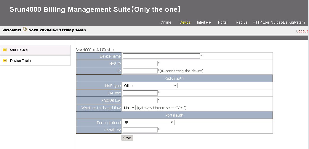
4. Configure the following parameters and then click Save to add an access device:
¡ Device name—Enter the device name of the NAS (the device name is BRAS in this example).
¡ NAS IP—Enter the IP address of the NAS (10.1.1.1, the IP address of interface LoopBack0 on the BRAS device in this example).
¡ IP—Enter the IP address of the host where the Srun software is installed (4.4.4.2 in this example).
¡ NAS type—Specify the NAS type.
¡ RADIUS key—Enter the key used for communication between the NAS and the RADIUS server (123456 in this example).
Figure 48 Adding a device

5. (Optional.) Click Radius > Add RADIUS Attributes to add RADIUS attributes. This example uses the following attributes:
¡ User-Name (RADIUS attribute 1)—Name to identify the user.
¡ Framed-IP-Address (RADIUS attribute 8)—IP address of the user.
¡ Web-URL (H3C proprietary RADIUS attribute 250)—Redirect URL for users. This attribute is used in conjunction with the Auth-Detail-Result attribute.
¡ Auth-Detail-Result (H3C proprietary RADIUS attribute 246)—Authentication result details. Supported values are:
- 0—Normal user. In this case, the server will cancel assigning attribute 250 and allow the user to access any network resources.
- 1—Defaulting user. In this case, the server will assign attribute 250 and allow the user to access network resources on the URL allowlist. If the user accesses other network resources, the requests will be redirected to the URL defined in attribute 250.
6. Click Radius Trust Setting, and click Generate on the upper right corner to generate trust settings.
7. Re-enable the RADIUS service for the trust settings to take effect.
To re-enable the RADIUS service, access the CLI of the Srun server, execute the killall radiusd command to disable the RADIUS service and then execute the /srun3/radius/sbin/radiusd & command to enable the RADIUS service.
Figure 49 Re-enabling the RADIUS service

8. Open a web browser, type https://4.4.4.2:8080 to log in to the server to configure policies and users.
9. (Optional.) Configure a control policy:
a. Click Strategy > Control, and then click Add.
b. Enter the policy name Rate-limit 100M.
c. Select the added attribute in step 5 for the self-defined attributes field.
d. Use default settings for other fields, and click Save.
10. (Optional.) Configure a billing policy:
a. Click Strategy > Billing, and click Add.
b. Enter 100 yuan each month in the Title field.
c. Use default settings for other fields, and click Save.
11. (Optional.) Configure a product policy:
a. Click Strategy > Product, and click Add.
b. Enter PPPoE user policy in the Product Name field.
c. Select 100 yuan each month for the Billing Strategy field.
d. Select Rate-limit 100M for the Control Strategy field.
12. Add user Host A:
a. Click Account > Add.
b. Specify the account name and password for Host A. In this example, account name user1 and password pass1 are used.
c. (Optional.) Select the group pppoe(ID:16), select PPPoE user policy, and enter 500 in the text box.
d. Use default settings for other fields, and click save.
Verifying the configuration
# After the PPPoE client software is installed on a host, the host can use the correct username and password to access Internet through the BRAS. After the user logs in successfully, execute the display access-user command on the BRAS to view PPP user information.
[BRAS] display access-user interface ten-gigabitethernet 3/1/1.1
UserID Interface IP address MAC address S-/C-VLAN
Username Access type
IPv6 address
0xc XGE3/1/1.1 3.3.3.2 00e0-0001-0001 20/10
user1 PPPoE
2003::F85B:7EE1:1410:74C9
To view the dynamic port block entries generated for users on the device, execute the display nat port-block dynamic command.
# When the charge of a user is overdue, the AAA server assigns the following attributes to the user:
user-name =user1, H3C-ISP-ID =nat_coa,h3c-web-url = "http://4.4.4.5/xxx",H3C-Auth_Detail_Result = 1
These attributes are explained as follows:
user-name =user1 //The username of the defaulting user is user1.
H3C-ISP-ID =nat_coa //The new ISP domain named nat_coa is assigned to the defaulting user.
H3C-Auth-Detail-Result=1 //The value 1 means the user is a defaulting user and can access only addresses on the URL allowlist. When the user accesses an address not on the URL allowlist through HTTP or HTTPS, the packets are redirected to the website specified in the H3C-WEB-URL attribute.
H3c-WEB-URL="http://4.4.4.5/xxx" //This attribute specifies the website to which packets from the defaulting user are redirected.
After coming online again, the user can access only addresses on the URL allowlist. When the user accesses an address not on the URL allowlist through HTTP, the packets are redirected to the website http://4.4.4.5/xxx. For example, when you enter http://www.163.com/ in the address bar of a browser, you are redirected to the payment page.
# After the user pays, the AAA server assigns the following attributes to the user:
user-name =user1 , H3C-ISP-ID =dm1 ,H3C-Auth_Detail_Result = 0
These attributes are explained as follows:
user-name =user1 //The username of the paying user is user1.
H3C-ISP-ID =dm1 //The ISP domain named dm1 is assigned to the user who has paid, and the user group named qianfei is removed from the user.
H3C-Auth-Detail-Result=0 //The value 0 means the redirection action is canceled for the user.
After the user comes online again, the user can access any network resources. For example, when you enter http://www.baidu.com/ in the address bar of a browser, the Baidu page can open normally.
Configuration files
#
failover group failgrp id 1
bind slot 5 primary
bind slot 6 secondary
#
dhcp enable
#
ipv6 dhcp prefix-pool 1 prefix 2003::/48 assign-len 64
#
object-group ip address freeurl_ipv4
0 network host address 4.4.4.5
10 network host address 4.4.4.6
20 network host address 4.4.4.7
30 network host address 4.4.4.8
#
object-group ipv6 address freeurl_ipv6
0 network host address 4::5
10 network host address 4::6
20 network host address 4::7
30 network host address 4::8
#
traffic classifier normal_in_ipv4 operator or
if-match acl name normal_ip
#
traffic classifier normal_in_ipv6 operator or
if-match acl ipv6 name normal_ip
#
traffic classifier normal_out_ipv4 operator or
if-match acl name normal_ip
#
traffic classifier normal_out_ipv6 operator or
if-match acl ipv6 name normal_ip
#
traffic classifier qianfei_in_ipv4 operator or
if-match acl name qianfei_in
#
traffic classifier qianfei_in_ipv6 operator or
if-match acl ipv6 name qianfei_in
#
traffic classifier qianfei_ip_deny operator or
if-match acl name qianfei_ip
if-match acl ipv6 name qianfei_ip
#
traffic classifier qianfei_out operator or
if-match acl name qianfei_out
if-match acl ipv6 name qianfei_out
#
traffic behavior normal_in_ipv4
bind nat-instance inst
#
traffic behavior normal_in_ipv6
filter permit
#
traffic behavior normal_out_ipv4
filter permit
#
traffic behavior normal_out_ipv6
filter permit
#
traffic behavior qianfei_in_ipv4
free account
bind nat-instance inst
#
traffic behavior qianfei_in_ipv6
filter permit
free account
#
traffic behavior qianfei_ip_deny
filter deny
free account
#
traffic behavior qianfei_out
filter permit
free account
#
qos policy in
classifier qianfei_in_ipv4 behavior qianfei_in_ipv4
classifier qianfei_in_ipv6 behavior qianfei_in_ipv6
classifier qianfei_ip_deny behavior qianfei_ip_deny
classifier normal_in_ipv4 behavior normal_in_ipv4
classifier normal_in_ipv6 behavior normal_in_ipv6
#
qos policy out
classifier qianfei_out behavior qianfei_out
classifier qianfei_ip_deny behavior qianfei_ip_deny
classifier normal_out_ipv4 behavior normal_out_ipv4
classifier normal_out_ipv6 behavior normal_out_ipv6
#
ip pool pool1 bas local
gateway 3.3.3.1 mask 255.255.255.0
dns-list 4.4.4.7 4.4.4.8
forbidden-ip 3.3.3.1
#
ipv6 pool ndra
prefix-pool 1 export-route
#
interface Virtual-Template1
ppp authentication-mode pap chap domain default enable dm1
undo ipv6 nd ra halt
#
interface LoopBack0
ip address 10.1.1.1 255.255.255.255
#
interface Ten-GigabitEthernet3/1/1.1
local-proxy-arp enable
proxy-arp enable
qos apply policy in inbound
qos apply policy out outbound
user-vlan dot1q vid 20 second-dot1q 10
vlan-termination broadcast enable
ipv6 dhcp select server
ipv6 address auto link-local
undo ipv6 nd ra halt
pppoe-server access-line-id bas-info cn-163
pppoe-server nas-port-id interface ten-gigabitethernet 3/1/1
pppoe-server bind virtual-template 1
#
interface Ten-GigabitEthernet3/1/2
ip address 4.4.4.1 255.255.255.0
ipv6 address 4::1 64
#
interface Ten-GigabitEthernet3/1/3
ip address 6.6.6.1 255.255.255.0
ipv6 address 6::1 64
#
customlog format cmcc
customlog host 4.4.4.9 port 1000 export cmcc-sessionlog cmcc-userlog sysname logserver01
customlog host 4.4.4.10 port 1000 export cmcc-sessionlog cmcc-userlog sysname logserver02
customlog host source LoopBack0
customlog timestamp localtime
#
ip route-static 0.0.0.0 0 6.1.1.2
ipv6 route-static :: 0 6::2
#
acl advanced 3000
rule 5 permit ip source 3.3.3.0 0.0.0.255
#
acl advanced name normal_ip
rule 0 permit ip user-group normal
#
acl advanced name qianfei_in
rule 0 permit ip destination object-group freeurl_ipv4 user-group qianfei
#
acl advanced name qianfei_ip
rule 0 permit ip user-group qianfei
#
acl advanced name qianfei_out
rule 0 permit ip source object-group freeurl_ipv4 user-group qianfei
#
acl ipv6 advanced name normal_ip
rule 0 permit ipv6 user-group normal
#
acl ipv6 advanced name qianfei_in
rule 0 permit ipv6 destination object-group freeurl_ipv6 user-group qianfei
#
acl ipv6 advanced name qianfei_ip
rule 0 permit ipv6 user-group qianfei
#
acl ipv6 advanced name qianfei_out
rule 0 permit ipv6 source object-group freeurl_ipv6 user-group qianfei
#
radius scheme rs1
primary authentication 4.4.4.2
primary accounting 4.4.4.2
secondary authentication 4.4.4.3
secondary accounting 4.4.4.3
key authentication cipher $c$3$Op8/zHukkwxWVrqrnhlG4cX2ENppi8Flrg==
key accounting cipher $c$3$D43K/vF4D75aBIayM49pAqY2nNetyXbfmQ==
user-name-format without-domain
nas-ip 10.1.1.1
attribute 25 car
#
radius dynamic-author server
client ip 4.4.4.2 key cipher $c$3$urw7L0vJRjunR+9c6H1vOWRqtselQcngOA==
client ip 4.4.4.3 key cipher $c$3$LUrPmr7bsRS0xbLPuuct/FzHatVHKROzcQ==
#
domain name dm1
authorization-attribute ip-pool pool1
authorization-attribute ipv6-nd-prefix-pool ndra
authorization-attribute primary-dns ipv6 8::8
authorization-attribute redirect-times 2
authentication ppp radius-scheme rs1
authorization ppp radius-scheme rs1
accounting ppp radius-scheme rs1
user-address-type private-ipv4
user-group name normal bind nat-instance inst
#
domain name nat_coa
authorization-attribute ip-pool pool1
authorization-attribute ipv6-nd-prefix-pool ndra
authorization-attribute primary-dns ipv6 8::8
authorization-attribute redirect-times 2
authentication ppp radius-scheme rs1
authorization ppp radius-scheme rs1
accounting ppp radius-scheme rs1
user-address-type private-ipv4
user-group name qianfei bind nat-instance inst
#
user-group normal
#
user-group qianfei
#
service-instance-group sgrp
failover-group failgrp
#
nat alg pptp
nat mapping-behavior endpoint-independent tcp udp
nat log enable
nat log port-block port-usage threshold 90
nat log port-block-assign
nat log port-block-withdraw
#
nat address-group 1
port-range 1024 65535
port-block block-size 256 extended-block-number 3 extended-block-size 1024
address 6.6.6.2 6.6.6.255
#
nat instance inst id 1
service-instance-group sgrp
nat outbound 3000 address-group 1
#
Broadband dual-stack user dynamic ITA service configuration example (PPPoE-NAT collaboration+prefix assignment by ND prefix pool)
The broadband service is a basic service of a service provider MAN. Broadband users use the PPPoE single-stack or dual-stack method to access. The BRAS performs service control, and the AAA server performs authentication, authorization, and accounting. Additionally, the BRAS performs accounting at different charge rates for user data based on destination addresses.
Network configuration
As shown in Figure 44, Router A acts as a BRAS, and provides access services for broadband users. The network requirements are as follows:
· Overall:
¡ Broadband user Host A accesses the BRAS in PPPoE mode through a Layer 2 network.
¡ The BRAS acts as a DHCP server to allocate an IPv4 address to the user.
¡ The BRAS acts as a PPPoE server to allocate an IPv6 address to Host A through ND. In this scenario, Host A obtains an IPv6 address prefix through the ND RA packets, and obtains an IPv6 interface ID through IPv6CP negotiation. An IPv6 global unicast address is generated based on the IPv6 address prefix and IPv6 interface ID. The IPv6 address prefix in the RA packets is obtained from the ND prefix pool.
¡ NAT collaborates with the BRAS. When a broadband user passes authentication and is assigned a private IPv4 address, a public address (111.8.0.200) and port block are assigned to the user. NAT is not performed for IPv6 addresses.
¡ The Srun software is deployed on the server to manage authentication and accounting.
· ITA:
¡ After a user comes online, the RADIUS server dynamically authorize different ITA policies to different services of the user.
- For Xunlei traffic, the downlink CIR is 30 Mbps, the IPv4 accounting level is level 1, and the IPv6 accounting level is level 2.
- For Tianyiyun traffic, the downlink CIR is 20 Mbps, the IPv4 accounting level is level 3, and the IPv6 accounting level is level 4.
- For both Xunlei and Tianyiyun traffic, the uplink CIR is 20 Mbps, the downlink CIR is 30 Mbps, the IPv4 accounting level is level 5, and the IPv6 accounting level is level 6.
- The RADIUS server performs separate accounting for ITA traffic and non- ITA traffic.
- All levels of traffic under the ITA policy are merged, and the lowest accounting level configured in the policy is reported to the accounting server.
¡ The RADIUS server can cancel the authorized ITA policy by issuing a specific named ITA policy (default in this example).
· AAA:
¡ Two RADIUS servers are deployed, one primary and one secondary.
¡ Interface LoopBack0 is used as the source interface for sending RADIUS packets on the BRAS.
¡ The function of interpreting the RADIUS class attribute (attribute 25) as CAR parameters is enabled.
¡ A user that encounters accounting-start failures stays online.
Figure 50 Network diagram
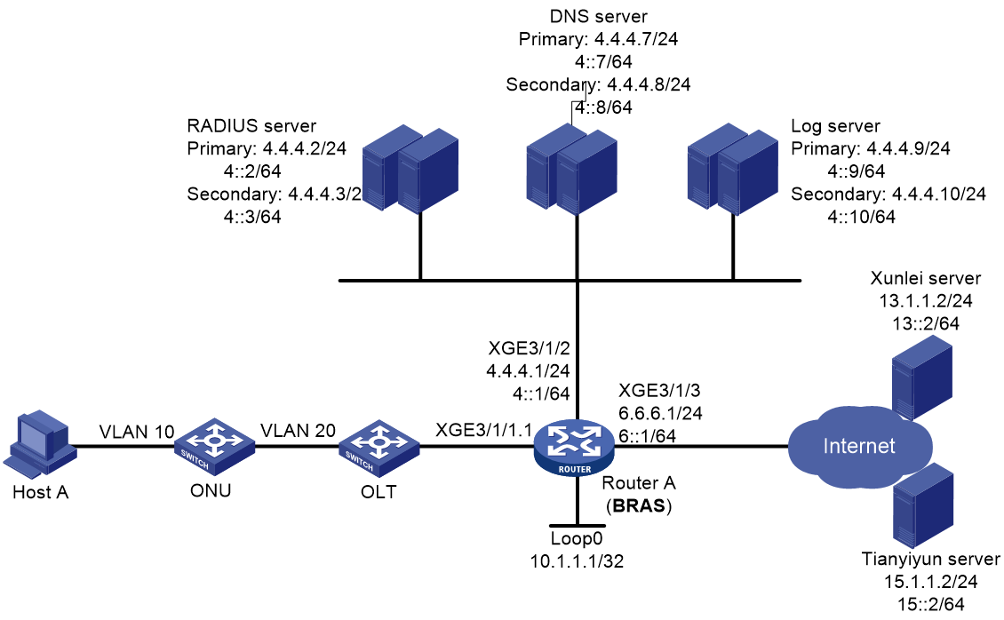
Analysis
· In the local domain, bind load balancing user groups to a NAT instance. In this way, a user can carry the user group attribute after successfully passing authentication and coming online. The AAA server does not need to separately assign user group attributes.
· Create user groups, and assign the same user group attribute to users in the same domain. Then, an ACL can recognize traffic by user group name and then the traffic can be redirected to a NAT instance.
· In an ISP domain, you must configure the user address type as private IPv4 address to trigger NAT-BRAS collaboration.
· In the environment where a CGN module is used to provide the NAT feature, for dynamic NAT or port block-based NAT, you must bind a NAT address group to a backup group with the CGN module.
· To perform separate accounting for ITA traffic and non- ITA traffic, execute the traffic-separate enable command.
· To merge all levels of traffic under an ITA policy and report the lowest accounting level to the accounting server, execute the accounting-merge enable command to enable accounting merge.
Procedure
Configuring IP addresses and routes
# Assign IPv4 address 4.4.4.1/24 and IPv6 address 4::1/64 to Ten-GigabitEthernet 3/1/2 on the BRAS.
<BRAS> system-view
[BRAS] interface ten-gigabitethernet 3/1/2
[BRAS-Ten-GigabitEthernet3/1/2] ip address 4.4.4.1 24
[BRAS-Ten-GigabitEthernet3/1/2] ipv6 address 4::1 64
[BRAS-Ten-GigabitEthernet3/1/2] quit
# Assign IPv4 address 6.6.6.1/24 and IPv6 address 6::1/64 to Ten-GigabitEthernet 3/1/3 on the BRAS.
[BRAS] interface ten-gigabitethernet 3/1/3
[BRAS-Ten-GigabitEthernet3/1/3] ip address 6.6.6.1 24
[BRAS-Ten-GigabitEthernet3/1/3] ipv6 address 6::1 64
[BRAS-Ten-GigabitEthernet3/1/3] quit
# Configure default routes to the Internet.
[BRAS] ip route-static 0.0.0.0 0 6.1.1.2
[BRAS] ipv6 route-static :: 0 6::2
Configuring the DNS servers
In this example, Windows Server 2016 is used to describe the basic DNS server configuration. The configurations for the primary and secondary DNS servers are similar. This section uses the primary DNS server as an example. For information about configuring the log servers, see the corresponding software descriptions.
To configure a DNS server:
1. Install the DNS component:
a. Log in to the server, click Windows, and select Server Manager.
b. Click Add Roles and Features, and configure DNS.
c. On the Before you begin page, click Next.
d. On the Select installation type page, use the default option (Role-based or feature-based installation), and click Next.
e. On the Select destination server page, use the default option (Select a server from the server pool), and click Next.
f. On the Select server roles page, select DNS Server. On the Add Roles and Features Wizard page that opens, click Add Features, and then click Next.
g. On the Select features page, use the default settings, and click Next.
h. On the DNS Server page, click Next.
i. Click Install on the Confirm installation selections page and wait for the installation to complete.
j. Once installation completes, click Close to complete the installation of the DNS component.
2. Create an IPv4 forward lookup zone:
a. On the Server Manager page, click Tools, and select DNS.
b. Right-click Forward Lookup Zones on the DNS Manager page and select New Zone.
c. On the New Zone Wizard page, click Next.
d. On the Zone Type page, select Primary zone, and click Next.
e. On the Zone Name page, enter zone name ipv4.test.com.
f. On the Zone File page, use the default settings and click Next.
g. On the Dynamic Update page, select Do not allow dynamic updates and click Next.
h. On the New Zone Wizard page, click Finish.
i. On the DNS Manager page, click Forward Lookup Zones, right-click ipv4.test.com, and click New Host.
j. On the New Host page, enter host name www, enter IP address 4.4.4.7, and click Add Host.
The IPv4 forward lookup zone has been successfully created.
3. Create an IPv4 reverse lookup zone:
a. Right-click Reverse Lookup Zones on the DNS Manager page and select New Zone.
b. On the New Zone Wizard page, click Next.
c. On the Zone Type page, select Primary zone, and click Next.
d. On the Reverse Lookup Zone Name page, select IPv4 Reverse Lookup Zone, and click Next.
e. On the Reverse Lookup Zone Name page, enter network ID 4.4.4, and click Next.
f. On the Zone File page, use the default settings and click Next.
g. On the Dynamic Update page, select Do not allow dynamic updates and click Next.
h. On the New Zone Wizard page, click Finish.
i. On the DNS Manager page, click Reverse Lookup Zones, right-click 4.4.4.in-addr.arpa.dns, and click New Pointer.
j. On the New Resource Record page, enter host IP address 4.4.4.7, enter host name www.ipv4.test.com, and click OK.
The IPv4 reverse lookup zone has been successfully created.
4. Create an IPv6 forward lookup zone:
a. On the Server Manager page, click Tools, and select DNS.
b. Right-click Forward Lookup Zones on the DNS Manager page and select New Zone.
c. On the New Zone Wizard page, click Next.
d. On the Zone Type page, select Primary zone, and click Next.
e. On the Zone Name page, enter zone name ipv6.test.com.
f. On the Zone File page, use the default settings and click Next.
g. On the Dynamic Update page, select Do not allow dynamic updates and click Next.
h. On the New Zone Wizard page, click Finish.
i. On the DNS Manager page, click Forward Lookup Zones, right-click ipv6.test.com, and click New Host.
j. On the New Host page, enter host name www, enter IP address 4::7, and click Add Host.
The IPv6 forward lookup zone has been successfully created.
5. Create an IPv6 reverse lookup zone:
a. Right-click Reverse Lookup Zones on the DNS Manager page and select New Zone.
b. On the New Zone Wizard page, click Next.
c. On the Zone Type page, select Primary zone, and click Next.
d. On the Reverse Lookup Zone Name page, select IPv6 Reverse Lookup Zone, and click Next.
e. On the Reverse Lookup Zone Name page, enter network ID 4000:0000:0000:0000::/64, and click Next.
f. On the Zone File page, use the default settings and click Next.
g. On the Dynamic Update page, select Do not allow dynamic updates and click Next.
h. On the New Zone Wizard page, click Finish.
i. On the DNS Manager page, click Reverse Lookup Zones, right-click 0.0.0.0.0.0.0.0.0.0.0.0.0.0.0.4.in-addr.arpa.dns, and click New Pointer.
j. On the New Resource Record page, enter host IP address 4000.0000.0000.0000.0000.0000.0000.0007, enter host name www.ipv6.test.com, and click OK.
The IPv6 reverse lookup zone has been successfully created.
Configuring the BRAS
1. Configure DHCP.
# Enable DHCP.
<BRAS> system-view
[BRAS] dhcp enable
# Create local BAS IP address pool pool1.
[BRAS] ip pool pool1 bas local
[BRAS-ip-pool-pool1] gateway 3.3.3.1 24
[BRAS-ip-pool-pool1] dns-list 4.4.4.7 4.4.4.8
# Exclude 3.3.3.1 from dynamic address allocation.
[BRAS-ip-pool-pool1] forbidden-ip 3.3.3.1
[BRAS-ip-pool-pool1] quit
# Create DHCPv6 prefix pool 1, specify prefix range 2003::/48 for prefix pool 1, and set the prefix length used for dynamic allocation to 64.
[BRAS] ipv6 dhcp prefix-pool 1 prefix 2003::/48 assign-len 64
# Create IPv6 address pool ndra, and then apply DHCPv6 prefix pool 1 to the IPv6 address pool.
[BRAS] ipv6 pool ndra
[BRAS-ipv6-pool-ndra] prefix-pool 1 export-route
[BRAS-ipv6-pool-ndra] quit
# Enable automatic link-local address generation on Ten-GigabitEthernet 3/1/1.1.
[BRAS] interface ten-gigabitethernet 3/1/1.1
[BRAS-Ten-GigabitEthernet3/1/1.1] ipv6 address auto link-local
# Disable RA message advertisement suppression on Ten-GigabitEthernet 3/1/1.1.
[BRAS-Ten-GigabitEthernet3/1/1.1] undo ipv6 nd ra halt
# Enable Ten-GigabitEthernet 3/1/1.1 to operate in DHCPv6 server mode.
[BRAS-Ten-GigabitEthernet3/1/1.1] ipv6 dhcp select server
[BRAS-Ten-GigabitEthernet3/1/1.1] quit
2. Configure global NAT.
a. Configure bindings between CGN cards and a failover group.
# Create failover group failgrp and enter its view.
[BRAS] failover group failgrp id 1
# Bind CGN cards to failover group failgrp: Configure slot 5 as the primary node and slot 6 as the secondary node.
[BRAS-failover-group-failgrp] bind slot 5 primary//If the specified slot supports CPU, you must specify the CPU parameter following the slot parameter.
[BRAS-failover-group-failgrp] bind slot 6 secondary
[BRAS-failover-group-failgrp] quit
b. Configure a service instance group.
# Create service instance group sgrp and enter its view.
[BRAS] service-instance-group sgrp
# Associate service instance group sgrp with failover group failgrp.
[BRAS-service-instance-group-sgrp] failover-group failgrp
[BRAS-service-instance-group-sgrp] quit
c. Configure an advanced ACL.
# Create advanced IPv4 ACL 3600.
[BRAS] acl advanced 3600
# Configure a rule for advanced IPv4 ACL 3600 to permit only packets from internal subnet 3.3.3.0/24. This ensures that IP address translation is available only for packets from users in internal subnet 3.3.3.0/24.
[BRAS-acl-ipv4-adv-3600] rule permit ip source 3.3.3.0 0.0.0.255
[BRAS-acl-ipv4-adv-3600] quit
d. Configure global NAT.
# Create address group 1. Add public address 111.8.0.200, set the port block size to 256, the number of extended port blocks to 3, and the number of ports in an extended port block to 1024.
[BRAS] nat address-group 1
[BRAS-address-group-1] address 111.8.0.200 111.8.0.200
[BRAS-address-group-1] port-range 1024 65535
[BRAS-address-group-1] port-block block-size 256 extended-block-number 3 extended-block-size 1024
[BRAS-address-group-1] quit
# Create NAT instance nat1.
[BRAS] nat instance nat1 id 1
# Associate service instance group sgrp with the NAT instance.
[BRAS-nat-instance-nat1] service-instance-group sgrp
# Configure an outbound NAT rule for NAT instance inst. Use address group 1 to translate packets permitted by ACL 3600.
[BRAS-nat-instance-nat1] nat outbound 3600 address-group 1
[BRAS-nat-instance-nat1] quit
e. Configure the three-tuple mode. The three-tuple includes source IP address, source port number, and protocol type.
# Configure the Endpoint-Independent Mapping mode for TCP and UDP packets and create EIM entries for TCP and UDP connections.
[BRAS] nat mapping-behavior endpoint-independent tcp udp
f. Enable NAT ALG.
|
|
NOTE: This example only introduces how to enable NAT ALG for FTP and PPTP. You can enable ALG for other protocols as needed. For more information, see the NAT configuration book. |
# Enable NAT ALG for FTP and PPTP.
[BRAS] nat alg ftp (Default setting)
[BRAS] nat alg pptp
g. Configure NAT logging.
|
|
NOTE: Log export consumes system resources. To avoid overconsumption of system resources, this example only introduces how to configure basic NAT logging. You can enable logging for other events as needed. For more information, see the NAT configuration book. |
# Enable NAT logging.
[BRAS] nat log enable
# Enable logging for port usage in port blocks and set the usage threshold to 90%.
[BRAS] nat log port-block port-usage threshold 90
# Enable NAT444 user logging for port block assignment events.
[BRAS] nat log port-block-assign
# Enable NAT444 user logging for port block withdrawal events.
[BRAS] nat log port-block-withdraw
# Enable fast log output.
[BRAS] customlog format cmcc
# Configure the timestamp of fast output logs to show the system time.
[BRAS] customlog timestamp localtime
# Specify the IP address of Loopback 0 as the source IP address for fast log output.
[BRAS] interface loopback 0
[BRAS-LoopBack0] ip address 10.1.1.1 32
[BRAS-LoopBack0] quit
[BRAS] customlog host source loopback0
# Output NAT session logs and NAT444 user logs in cmcc format to log hosts 4.4.4.9 and 4.4.4.10.
[BRAS] customlog host 4.4.4.9 port 1000 export cmcc-sessionlog cmcc-userlog sysname logserver01
[BRAS] customlog host 4.4.4.10 port 1000 export cmcc-sessionlog cmcc-userlog sysname logserver02
3. Create user groups.
# Create a user group named normal.
[BRAS] user-group normal
[BRAS-ugroup-normal] quit
# Create a user group named xunlei.
[BRAS] user-group xunlei
[BRAS-ugroup-xunlei] quit
# Create a user group named tianyiyun.
[BRAS] user-group tianyiyun
[BRAS-ugroup-tianyiyun] quit
# Create a user group named allapp.
[BRAS] user-group allapp
[BRAS-ugroup-allapp] quit
4. Configure an ITA policy for Xunlei traffic.
# Create an ITA policy named xunlei and enter its view.
[BRAS] ita policy xunlei
# Specify accounting method rs1 in the ITA policy.
[BRAS-ita-policy-xunlei] accounting-method radius-scheme rs1
# Specify traffic level 1 and count the level-1 traffic as IPv4 traffic, and set the outbound CIR to 30720 kbps (30 Mbps).
[BRAS-ita-policy-xunlei] accounting-level 1 ipv4 car outbound cir 30720
# Specify traffic level 2 and count the level-2 traffic as IPv6 traffic, and set the outbound CIR to 30720 kbps (30 Mbps).
[BRAS-ita-policy-xunlei] accounting-level 2 ipv6 car outbound cir 30720
# Specify user group xunlei for the ITA policy and bind the user group to NAT instance nat1.
[BRAS-ita-policy-xunlei] user-group name xunlei nat-instance nat1
# Enable accounting merge.
[BRAS-ita-policy-xunlei] accounting-merge enable
# Exclude the amount of ITA traffic from the overall traffic statistics that are sent to the accounting server.
[BRAS-ita-policy-xunlei] traffic-separate enable level 1 2
[BRAS-ita-policy-xunlei] quit
5. Configure an ITA policy for Tianyiyun traffic.
# Create an ITA policy named tianyiyun and enter its view.
[BRAS] ita policy tianyiyun
# Specify accounting method rs1 in the ITA policy.
[BRAS-ita-policy-tianyiyun] accounting-method radius-scheme rs1
# Specify traffic level 3 and count the level-3 traffic as IPv4 traffic, set the inbound CIR to 20480 kbps (20 Mbps), and set the outbound CIR to 30720 kbps (30 Mbps).
[BRAS-ita-policy-tianyiyun] accounting-level 3 ipv4 car inbound cir 20480 outbound cir 20480
# Specify traffic level 4 and count the level-4 traffic as IPv6 traffic, set the inbound CIR to 20480 kbps (20 Mbps), and set the outbound CIR to 30720 kbps (30 Mbps).
[BRAS-ita-policy-tianyiyun] accounting-level 4 ipv6 car inbound cir 20480 outbound cir 20480
# Specify user group tianyiyun for the ITA policy and bind the user group to NAT instance nat1.
[BRAS-ita-policy-tianyiyun] user-group name tianyiyun nat-instance nat1
# Enable accounting merge.
[BRAS-ita-policy-tianyiyun] accounting-merge enable
# Exclude the amount of ITA traffic from the overall traffic statistics that are sent to the accounting server.
[BRAS-ita-policy-tianyiyun] traffic-separate enable level 3 4
[BRAS-ita-policy-tianyiyun] quit
6. Configure an ITA policy for both Xunlei and Tianyiyun traffic.
# Create ITA policy named allapp and enter its view.
[BRAS] ita policy allapp
# Specify accounting method rs1 in the ITA policy.
[BRAS-ita-policy-allapp] accounting-method radius-scheme rs1
# Specify traffic level 5 and count the level-5 traffic as IPv4 traffic, set the inbound CIR to 20480 kbps (20 Mbps), and set the outbound CIR to 30720 kbps (30 Mbps).
[BRAS-ita-policy-allapp] accounting-level 5 ipv4 car inbound cir 20480 outbound cir 30720
# Specify traffic level 6 and count the level-5 traffic as IPv6 traffic, set the inbound CIR to 20480 kbps (20 Mbps), and set the outbound CIR to 30720 kbps (30 Mbps).
[BRAS-ita-policy-allapp] accounting-level 6 ipv6 car inbound cir 20480 outbound cir 30720
# Specify user group allapp for the ITA policy and bind the user group to NAT instance nat1.
[BRAS-ita-policy-allapp] user-group name allapp nat-instance nat1
# Enable accounting merge.
[BRAS-ita-policy-allapp] accounting-merge enable
# Exclude the amount of ITA traffic from the overall traffic statistics that are sent to the accounting server.
[BRAS-ita-policy-allapp] traffic-separate enable level 5 6
[BRAS-ita-policy-allapp] quit
7. Configure an empty ITA policy used to cancel authorized ITA policies.
# Create an ITA policy named default.
[BRAS] ita policy default
[BRAS-ita-policy-default] quit
8. Configure QoS policies for ITA traffic and non-ITA traffic.
a. Configure ACLs to match ITA Xunlei traffic.
# Configure IPv4 advanced ACL xunlei_in and IPv6 advanced ACL xunlei_in to match packets destined to the Xunlei server for users in user group xunlei.
[BRAS] acl advanced name xunlei_in
[BRAS-acl-ipv4-adv-xunlei_in] rule 0 permit ip destination 13.1.1.2 0 user-group xunlei
[BRAS-acl-ipv4-adv-xunlei_in] quit
[BRAS] acl ipv6 advanced name xunlei_in
[BRAS-acl-ipv6-adv-xunlei_in] rule 0 permit ipv6 destination 13::2 128 user-group xunlei
[BRAS-acl-ipv6-adv-xunlei_in] quit
# Configure IPv4 advanced ACL xunlei_out and IPv6 advanced ACL xunlei_out to match packets sourced from the Xunlei server for users in user group xunlei.
[BRAS] acl advanced name xunlei_out
[BRAS-acl-ipv4-adv-xunlei_out] rule 0 permit ip source 13.1.1.2 0 user-group xunlei
[BRAS-acl-ipv4-adv-xunlei_out] quit
[BRAS] acl ipv6 advanced name xunlei_out
[BRAS-acl-ipv6-adv-xunlei_out] rule 0 permit ipv6 source 13::2 128 user-group xunlei
[BRAS-acl-ipv6-adv-xunlei_out] quit
b. Configure ACLs to match ITA Tianyiyun traffic.
# Configure IPv4 advanced ACL tianyiyun_in and IPv6 advanced ACL tianyiyun_in to match packets destined to the Tianyiyun server for users in user group tianyiyun.
[BRAS] acl advanced name tianyiyun_in
[BRAS-acl-ipv4-adv-tianyiyun_in] rule 0 permit ip destination 15.1.1.2 0 user-group tianyiyun
[BRAS-acl-ipv4-adv-tianyiyun_in] quit
[BRAS] acl ipv6 advanced name tianyiyun_in
[BRAS-acl-ipv6-adv-tianyiyun_in] rule 0 permit ipv6 destination 15::2 128 user-group tianyiyun
[BRAS-acl-ipv6-adv-tianyiyun_in] quit
# Configure IPv4 advanced ACL tianyiyun_out and IPv6 advanced ACL tianyiyun_out to match packets sourced from the Tianyiyun server for users in user group tianyiyun.
[BRAS] acl advanced name tianyiyun_out
[BRAS-acl-ipv4-adv-tianyiyun_out] rule 0 permit ip source 15.1.1.2 0 user-group tianyiyun
[BRAS-acl-ipv4-adv-tianyiyun_out] quit
[BRAS] acl ipv6 advanced name tianyiyun_out
[BRAS-acl-ipv6-adv-tianyiyun_out] rule 0 permit ipv6 source 15::2 128 user-group tianyiyun
[BRAS-acl-ipv6-adv-tianyiyun_out] quit
c. Configure ACLs to match both ITA Xunlei traffic and ITA Tianyiyun traffic.
# Configure IPv4 advanced ACL allapp_in and IPv6 advanced ACL allapp_in to match packets destined to the Xunlei or Tianyiyun server for users in user group allapp.
[BRAS] acl advanced name allapp_in
[BRAS-acl-ipv4-adv-allapp_in] rule 0 permit ip destination 13.1.1.2 0 user-group allapp
[BRAS-acl-ipv4-adv-allapp_in] rule 5 permit ip destination 15.1.1.2 0 user-group allapp
[BRAS-acl-ipv4-adv-allapp_in] quit
[BRAS] acl ipv6 advanced name allapp_in
[BRAS-acl-ipv6-adv-allapp_in] rule 0 permit ipv6 destination 13::2 128 user-group allapp
[BRAS-acl-ipv6-adv-allapp_in] rule 5 permit ipv6 destination 15::2 128 user-group allapp
[BRAS-acl-ipv6-adv-allapp_in] quit
# Configure IPv4 advanced ACL allapp_out and IPv6 advanced ACL allapp_out to match packets sourced from the Xunlei or Tianyiyun server for users in user group allapp.
[BRAS] acl advanced name allapp_out
[BRAS-acl-ipv4-adv-allapp_out] rule 0 permit ip source 13.1.1.2 0 user-group allapp
[BRAS-acl-ipv4-adv-allapp_out] rule 5 permit ip source 15.1.1.2 0 user-group allapp
[BRAS-acl-ipv4-adv-allapp_out] quit
[BRAS] acl ipv6 advanced name allapp_out
[BRAS-acl-ipv6-adv-allapp_out] rule 0 permit ipv6 source 13::2 128 user-group allapp
[BRAS-acl-ipv6-adv-allapp_out] rule 5 permit ipv6 source 15::2 128 user-group allapp
[BRAS-acl-ipv6-adv-allapp_out] quit
d. Configure ACLs to match non-ITA Xunlei traffic.
# Configure IPv4 advanced ACL xunlei_normal_ip and IPv6 advanced ACL xunlei_normal_ip to match all packets of users in user group xunlei.
[BRAS] acl advanced name xunlei_normal_ip
[BRAS-acl-ipv4-adv-xunlei_normal_ip] rule 0 permit ip user-group xunlei
[BRAS-acl-ipv4-adv-xunlei_normal_ip] quit
[BRAS] acl ipv6 advanced name xunlei_normal_ip
[BRAS-acl-ipv6-adv-xunlei_normal_ip] rule 0 permit ipv6 user-group xunlei
[BRAS-acl-ipv6-adv-xunlei_normal_ip] quit
e. Configure ACLs to match non-ITA Tianyiyun traffic.
# Configure IPv4 advanced ACL tianyiyun_normal_ip and IPv6 advanced ACL tianyiyun_normal_ip to match all IP packets of users in user group tianyiyun.
[BRAS] acl advanced name tianyiyun_normal_ip
[BRAS-acl-ipv4-adv-tianyiyun_normal_ip] rule 0 permit ip user-group tianyiyun
[BRAS-acl-ipv4-adv-tianyiyun_normal_ip] quit
[BRAS] acl ipv6 advanced name tianyiyun_normal_ip
[BRAS-acl-ipv6-adv-tianyiyun_normal_ip] rule 0 permit ipv6 user-group tianyiyun
[BRAS-acl-ipv6-adv-tianyiyun_normal_ip] quit
f. Configure ACLs to match non-ITA Xunlei traffic and non-ITA Tianyiyun traffic.
# Configure IPv4 advanced ACL allapp_normal_ip and IPv6 advanced ACL allapp_normal_ip to match all IP packets of users in user group allapp.
[BRAS] acl advanced name allapp_normal_ip
[BRAS-acl-ipv4-adv-allapp_normal_ip] rule 0 permit ip user-group allapp
[BRAS-acl-ipv4-adv-allapp_normal_ip] quit
[BRAS] acl ipv6 advanced name allapp_normal_ip
[BRAS-acl-ipv6-adv-allapp_normal_ip] rule 0 permit ipv6 user-group allapp
[BRAS-acl-ipv6-adv-allapp_normal_ip] quit
g. Configure ACLs to match non-ITA common traffic.
# Configure IPv4 advanced ACL normal_ip and IPv6 advanced ACL normal_ip to match all IP packets of users in user group normal.
[BRAS] acl advanced name normal_ip
[BRAS-acl-ipv4-adv-normal_ip] rule 0 permit ip user-group normal
[BRAS-acl-ipv4-adv-normal_ip] quit
[BRAS] acl ipv6 advanced name normal_ip
[BRAS-acl-ipv6-adv-normal_ip] rule 0 permit ipv6 user-group normal
[BRAS-acl-ipv6-adv-normal_ip] quit
9. Configure traffic classes and traffic behaviors for ITA Xunlei traffic.
# Create a traffic class named xunlei_in_ipv4, and use ACL xunlei_in as the match criterion.
[BRAS] traffic classifier xunlei_in_ipv4 operator or
[BRAS-classifier-xunlei_in_ipv4] if-match acl name xunlei_in
[BRAS-classifier-xunlei_in_ipv4] quit
# Create a traffic behavior named xunlei_in_ipv4, and configure the traffic behavior to count traffic in bytes, mark traffic with accounting level 1, and bind the traffic to NAT instance 1.
[BRAS] traffic behavior xunlei_in_ipv4
[BRAS-behavior-xunlei_in_ipv4] accounting byte
[BRAS-behavior-xunlei_in_ipv4] remark account-level 1
[BRAS-behavior-xunlei_in_ipv4] bind nat-instance nat1
[BRAS-behavior-xunlei_in_ipv4] quit
# Create a traffic class named xunlei_out_ipv4, and use ACL xunlei_out as the match criterion.
[BRAS] traffic classifier xunlei_out_ipv4 operator or
[BRAS-classifier-xunlei_out_ipv4] if-match acl name xunlei_out
[BRAS-classifier-xunlei_out_ipv4] quit
# Create a traffic behavior named xunlei_out_ipv4, and configure the traffic behavior to count traffic in bytes and mark traffic with accounting level 1.
[BRAS] traffic behavior xunlei_out_ipv4
[BRAS-behavior-xunlei_out_ipv4] accounting byte
[BRAS-behavior-xunlei_out_ipv4] remark account-level 1
[BRAS-behavior-xunlei_out_ipv4] quit
# Create a traffic class named xunlei_in_ipv6, and use ACL xunlei_in as the match criterion.
[BRAS] traffic classifier xunlei_in_ipv6 operator or
[BRAS-classifier-xunlei_in_ipv6] if-match acl ipv6 name xunlei_in
[BRAS-classifier-xunlei_in_ipv6] quit
# Create a traffic behavior named xunlei_in_ipv6, and configure the traffic behavior to count traffic in bytes and mark traffic with accounting level 2.
[BRAS] traffic behavior xunlei_in_ipv6
[BRAS-behavior-xunlei_in_ipv6] accounting byte
[BRAS-behavior-xunlei_in_ipv6] remark account-level 2
[BRAS-behavior-xunlei_in_ipv6] quit
# Create a traffic class named xunlei_out_ipv6, and use ACL xunlei_out as the match criterion.
[BRAS] traffic classifier xunlei_out_ipv6 operator or
[BRAS-classifier-xunlei_out_ipv6] if-match acl ipv6 name xunlei_out
[BRAS-classifier-xunlei_out_ipv6] quit
# Create a traffic behavior named xunlei_out_ipv6, and configure the traffic behavior to count traffic in bytes and mark traffic with accounting level 2.
[BRAS] traffic behavior xunlei_out_ipv6
[BRAS-behavior-xunlei_out_ipv6] accounting byte
[BRAS-behavior-xunlei_out_ipv6] remark account-level 2
[BRAS-behavior-xunlei_out_ipv6] quit
10. Configure traffic classes and traffic behaviors for ITA Tianyiyun traffic.
# Create a traffic class named tianyiyun_in_ipv4, and use ACL tianyiyun_in as the match criterion.
[BRAS] traffic classifier tianyiyun_in_ipv4 operator or
[BRAS-classifier-tianyiyun_in_ipv4] if-match acl name tianyiyun_in
[BRAS-classifier-tianyiyun_in_ipv4] quit
# Create a traffic behavior named tianyiyun_in_ipv4, and configure the traffic behavior to count traffic in bytes, mark traffic with accounting level 3, and bind NAT instance nat1.
[BRAS] traffic behavior tianyiyun_in_ipv4
[BRAS-behavior-tianyiyun_in_ipv4] accounting byte
[BRAS-behavior-tianyiyun_in_ipv4] remark account-level 3
[BRAS-behavior-tianyiyun_in_ipv4] bind nat-instance nat1
[BRAS-behavior-tianyiyun_in_ipv4] quit
# Create a traffic class named tianyiyun_out_ipv4, and use ACL tianyiyun_out as the match criterion.
[BRAS] traffic classifier tianyiyun_out_ipv4 operator or
[BRAS-classifier-tianyiyun_out_ipv4] if-match acl name tianyiyun_out
[BRAS-classifier-tianyiyun_out_ipv4] quit
# Create a traffic behavior named tianyiyun_out_ipv4, and configure the traffic behavior to count traffic in bytes and mark traffic with accounting level 3.
[BRAS] traffic behavior tianyiyun_out_ipv4
[BRAS-behavior-tianyiyun_out_ipv4] accounting byte
[BRAS-behavior-tianyiyun_out_ipv4] remark account-level 3
[BRAS-behavior-tianyiyun_out_ipv4] quit
# Create a traffic class named tianyiyun_in_ipv6, and use ACL tianyiyun_in as the match criterion.
[BRAS] traffic classifier tianyiyun_in_ipv6 operator or
[BRAS-classifier-tianyiyun_in_ipv6] if-match acl ipv6 name tianyiyun_in
[BRAS-classifier-tianyiyun_in_ipv6] quit
# Create a traffic behavior named tianyiyun_in_ipv6, and configure the traffic behavior to count traffic in bytes and mark traffic with accounting level 4.
[BRAS] traffic behavior tianyiyun_in_ipv6
[BRAS-behavior-tianyiyun_in_ipv6] accounting byte
[BRAS-behavior-tianyiyun_in_ipv6] remark account-level 4
[BRAS-behavior-tianyiyun_in_ipv6] quit
# Create a traffic class named tianyiyun_out_ipv6, and use ACL tianyiyun_out as the match criterion.
[BRAS] traffic classifier tianyiyun_out_ipv6 operator or
[BRAS-classifier-tianyiyun_out_ipv6] if-match acl ipv6 name tianyiyun_out
[BRAS-classifier-tianyiyun_out_ipv6] quit
# Create a traffic behavior named tianyiyun_out_ipv6, and configure the traffic behavior to count traffic in bytes and mark traffic with accounting level 4.
[BRAS] traffic behavior tianyiyun_out_ipv6
[BRAS-behavior-tianyiyun_out_ipv6] accounting byte
[BRAS-behavior-tianyiyun_out_ipv6] remark account-level 4
[BRAS-behavior-tianyiyun_out_ipv6] quit
11. Configure traffic classes and traffic behaviors for both ITA Xunlei traffic and ITA Tianyiyun traffic.
# Create a traffic class named allapp_in_ipv4, and use ACL allapp_in as the match criterion.
[BRAS] traffic classifier allapp_in_ipv4 operator or
[BRAS-classifier-allapp_in_ipv4] if-match acl name allapp_in
[BRAS-classifier-allapp_in_ipv4] quit
# Create a traffic behavior named allapp_in_ipv4, and configure the traffic behavior to count traffic in bytes, mark traffic with accounting level 5, and bind NAT instance nat1.
[BRAS] traffic behavior allapp_in_ipv4
[BRAS-behavior-allapp_in_ipv4] accounting byte
[BRAS-behavior-allapp_in_ipv4] remark account-level 5
[BRAS-behavior-allapp_in_ipv4] bind nat-instance nat1
[BRAS-behavior-allapp_in_ipv4] quit
# Create a traffic class named allapp_out_ipv4, and use ACL allapp_out as the match criterion.
[BRAS] traffic classifier allapp_out_ipv4 operator or
[BRAS-classifier-allapp_out_ipv4] if-match acl name allapp_out
[BRAS-classifier-allapp_out_ipv4] quit
# Create a traffic behavior named allapp_out_ipv4, and configure the traffic behavior to count traffic in bytes and mark traffic with accounting level 5.
[BRAS] traffic behavior allapp_out_ipv4
[BRAS-behavior-allapp_out_ipv4] accounting byte
[BRAS-behavior-allapp_out_ipv4] remark account-level 5
[BRAS-behavior-allapp_out_ipv4] quit
# Create a traffic class named allapp_in_ipv6, and use ACL allapp_in as the match criterion.
[BRAS] traffic classifier allapp_in_ipv6 operator or
[BRAS-classifier-allapp_in_ipv6] if-match acl ipv6 name allapp_in
[BRAS-classifier-allapp_in_ipv6] quit
# Create a traffic behavior named allapp_in_ipv6, and configure the traffic behavior to count traffic in bytes and mark traffic with accounting level 6.
[BRAS] traffic behavior allapp_in_ipv6
[BRAS-behavior-allapp_in_ipv6] accounting byte
[BRAS-behavior-allapp_in_ipv6] remark account-level 6
[BRAS-behavior-allapp_in_ipv6] quit
# Create a traffic class named allapp_out_ipv6, and use ACL allapp_out as the match criterion.
[BRAS] traffic classifier allapp_out_ipv6 operator or
[BRAS-classifier-allapp_out_ipv6] if-match acl ipv6 name allapp_out
[BRAS-classifier-allapp_out_ipv6] quit
# Create a traffic behavior named allapp_out_ipv6, and configure the traffic behavior to count traffic in bytes and mark traffic with accounting level 6.
[BRAS] traffic behavior allapp_out_ipv6
[BRAS-behavior-allapp_out_ipv6] accounting byte
[BRAS-behavior-allapp_out_ipv6] remark account-level 6
[BRAS-behavior-allapp_out_ipv6] quit
12. Configure traffic classes and traffic behaviors for non-ITA Xunlei traffic.
# Create a traffic class named xunlei_normal_in_ipv4, and use ACL xunlei_normal_ip as the match criterion.
[BRAS] traffic classifier xunlei_normal_in_ipv4 operator or
[BRAS-classifier-xunlei_normal_in_ipv4] if-match acl name xunlei_normal_ip
[BRAS-classifier-xunlei_normal_in_ipv4] quit
# Create a traffic behavior named xunlei_normal_in_ipv4, and configure the traffic behavior to count traffic in bytes and bind NAT instance nat1.
[BRAS] traffic behavior xunlei_normal_in_ipv4
[BRAS-behavior-xunlei_normal_in_ipv4] accounting byte
[BRAS-behavior-xunlei_normal_in_ipv4] bind nat-instance nat1
[BRAS-behavior-xunlei_normal_in_ipv4] quit
# Create a traffic class named xunlei_normal_out_ipv4, and use ACL xunlei_normal_ip as the match criterion.
[BRAS] traffic classifier xunlei_normal_out_ipv4 operator or
[BRAS-classifier-xunlei_normal_out_ipv4] if-match acl name xunlei_normal_ip
[BRAS-classifier-xunlei_normal_out_ipv4] quit
# Create a traffic behavior named xunlei_normal_out_ipv4 to permit all IPv4 packets to a user in user group xunlei.
[BRAS] traffic behavior xunlei_normal_out_ipv4
[BRAS-behavior-xunlei_normal_out_ipv4] filter permit
[BRAS-behavior-xunlei_normal_out_ipv4] quit
# Create a traffic class named xunlei_normal_in_ipv6, and use ACL xunlei_normal_ip as the match criterion.
[BRAS] traffic classifier xunlei_normal_in_ipv6 operator or
[BRAS-classifier-xunlei_normal_in_ipv6] if-match acl ipv6 name xunlei_normal_ip
[BRAS-classifier-xunlei_normal_in_ipv6] quit
# Create a traffic behavior named xunlei_normal_in_ipv6 to permit all IPv6 packets from a user in user group xunlei.
[BRAS] traffic behavior xunlei_normal_in_ipv6
[BRAS-behavior-xunlei_normal_in_ipv6] filter permit
[BRAS-behavior-xunlei_normal_in_ipv6] quit
# Create a traffic class named xunlei_normal_out_ipv6, and use ACL xunlei_normal_ip as the match criterion.
[BRAS] traffic classifier xunlei_normal_out_ipv6 operator or
[BRAS-classifier-xunlei_normal_out_ipv6] if-match acl ipv6 name xunlei_normal_ip
[BRAS-classifier-xunlei_normal_out_ipv6] quit
# Create a traffic behavior named xunlei_normal_out_ipv6 to permit all IPv6 packets to a user in user group xunlei.
[BRAS] traffic behavior xunlei_normal_out_ipv6
[BRAS-behavior-xunlei_normal_out_ipv6] filter permit
[BRAS-behavior-xunlei_normal_out_ipv6] quit
13. Configure traffic classes and traffic behaviors for non-ITA Tianyiyun traffic.
# Create a traffic class named tianyiyun_normal_in_ipv4, and use ACL tianyiyun_normal_ip as the match criterion.
[BRAS] traffic classifier tianyiyun_normal_in_ipv4 operator or
[BRAS-classifier-tianyiyun_normal_in_ipv4] if-match acl name tianyiyun_normal_ip
[BRAS-classifier-tianyiyun_normal_in_ipv4] quit
# Create a traffic behavior named tianyiyun_normal_in_ipv4, and configure the traffic behavior to count traffic in bytes and bind NAT instance nat1.
[BRAS] traffic behavior tianyiyun_normal_in_ipv4
[BRAS-behavior-tianyiyun_normal_in_ipv4] accounting byte
[BRAS-behavior-tianyiyun_normal_in_ipv4] bind nat-instance nat1
[BRAS-behavior-tianyiyun_normal_in_ipv4] quit
# Create a traffic class named tianyiyun_normal_out_ipv4, and use ACL tianyiyun_normal_ip as the match criterion.
[BRAS] traffic classifier tianyiyun_normal_out_ipv4 operator or
[BRAS-classifier-tianyiyun_normal_out_ipv4] if-match acl name tianyiyun_normal_ip
[BRAS-classifier-tianyiyun_normal_out_ipv4] quit
# Create a traffic behavior named tianyiyun_normal_out_ipv4 to permit all IPv4 packets to a user in user group tianyiyun.
[BRAS] traffic behavior tianyiyun_normal_out_ipv4
[BRAS-behavior-tianyiyun_normal_out_ipv4] filter permit
[BRAS-behavior-tianyiyun_normal_out_ipv4] quit
# Create a traffic class named tianyiyun_normal_in_ipv6, and use ACL tianyiyun_normal_ip as the match criterion.
[BRAS] traffic classifier tianyiyun_normal_in_ipv6 operator or
[BRAS-classifier-tianyiyun_normal_in_ipv6] if-match acl ipv6 name tianyiyun_normal_ip
[BRAS-classifier-tianyiyun_normal_in_ipv6] quit
# Create a traffic behavior named tianyiyun_normal_in_ipv6 to permit all IPv6 packets from a user in user group tianyiyun.
[BRAS] traffic behavior tianyiyun_normal_in_ipv6
[BRAS-behavior-tianyiyun_normal_in_ipv6] filter permit
[BRAS-behavior-tianyiyun_normal_in_ipv6] quit
# Create a traffic class named tianyiyun_normal_out_ipv6, and use ACL tianyiyun_normal_ip as the match criterion.
[BRAS] traffic classifier tianyiyun_normal_out_ipv6 operator or
[BRAS-classifier-tianyiyun_normal_out_ipv6] if-match acl ipv6 name tianyiyun_normal_ip
[BRAS-classifier-tianyiyun_normal_out_ipv6] quit
# Create a traffic behavior named tianyiyun_normal_out_ipv6 to permit all IPv6 packets to a user in user group tianyiyun.
[BRAS] traffic behavior tianyiyun_normal_out_ipv6
[BRAS-behavior-tianyiyun_normal_out_ipv6] filter permit
[BRAS-behavior-tianyiyun_normal_out_ipv6] quit
14. Configure traffic classes and traffic behaviors for non-ITA Xunlei traffic and non-ITA Tianyiyun traffic.
# Create a traffic class named allapp_normal_in_ipv4, and use ACL allapp_normal_ip as the match criterion.
[BRAS] traffic classifier allapp_normal_in_ipv4 operator or
[BRAS-classifier-allapp_normal_in_ipv4] if-match acl name allapp_normal_ip
[BRAS-classifier-allapp_normal_in_ipv4] quit
# Create a traffic behavior named allapp_normal_in_ipv4, and configure the traffic behavior to count traffic in bytes and bind NAT instance nat1.
[BRAS] traffic behavior allapp_normal_in_ipv4
[BRAS-behavior-allapp_normal_in_ipv4] accounting byte
[BRAS-behavior-allapp_normal_in_ipv4] bind nat-instance nat1
[BRAS-behavior-allapp_normal_in_ipv4] quit
# Create a traffic class named allapp_normal_out_ipv4, and use ACL allapp_normal_ip as the match criterion.
[BRAS] traffic classifier allapp_normal_out_ipv4 operator or
[BRAS-classifier-allapp_normal_out_ipv4] if-match acl name allapp_normal_ip
[BRAS-classifier-allapp_normal_out_ipv4] quit
# Create a traffic behavior named allapp_normal_out_ipv4 to permit all IPv4 packets to a user in user group allapp.
[BRAS] traffic behavior allapp_normal_out_ipv4
[BRAS-behavior-allapp_normal_out_ipv4] filter permit
[BRAS-behavior-allapp_normal_out_ipv4] quit
# Create a traffic class named allapp_normal_in_ipv6, and use ACL allapp_normal_ip as the match criterion.
[BRAS] traffic classifier allapp_normal_in_ipv6 operator or
[BRAS-classifier-allapp_normal_in_ipv6] if-match acl ipv6 name allapp_normal_ip
[BRAS-classifier-allapp_normal_in_ipv6] quit
# Create a traffic behavior named allapp_normal_in_ipv6 to permit all IPv6 packets from a user in user group allapp.
[BRAS] traffic behavior allapp_normal_in_ipv6
[BRAS-behavior-allapp_normal_in_ipv6] filter permit
[BRAS-behavior-allapp_normal_in_ipv6] quit
# Create a traffic class named allapp_normal_out_ipv6, and use ACL allapp_normal_ip as the match criterion.
[BRAS] traffic classifier allapp_normal_out_ipv6 operator or
[BRAS-classifier-allapp_normal_out_ipv6] if-match acl ipv6 name allapp_normal_ip
[BRAS-classifier-allapp_normal_out_ipv6] quit
# Create a traffic behavior named allapp_normal_out_ipv6 to permit all IPv6 packets to a user in user group allapp.
[BRAS] traffic behavior allapp_normal_out_ipv6
[BRAS-behavior-allapp_normal_out_ipv6] filter permit
[BRAS-behavior-allapp_normal_out_ipv6] quit
15. Configure traffic classes and traffic behaviors for non-ITA common traffic.
# Create a traffic class named normal_in_ipv4, and use ACL normal_ip as the match criterion.
[BRAS] traffic classifier normal_in_ipv4 operator or
[BRAS-classifier-normal_in_ipv4] if-match acl name normal_ip
[BRAS-classifier-normal_in_ipv4] quit
# Create a traffic behavior named normal_in_ipv4, and configure the traffic behavior to count traffic in bytes and bind NAT instance nat1.
[BRAS] traffic behavior normal_in_ipv4
[BRAS-behavior-normal_in_ipv4] accounting byte
[BRAS-behavior-normal_in_ipv4] bind nat-instance nat1
[BRAS-behavior-normal_in_ipv4] quit
# Create a traffic class named normal_out_ipv4, and use ACL normal_ip as the match criterion.
[BRAS] traffic classifier normal_out_ipv4 operator or
[BRAS-classifier-normal_out_ipv4] if-match acl name normal_ip
[BRAS-classifier-normal_out_ipv4] quit
# Create a traffic behavior named normal_out_ipv4 to permit all IPv4 packets to a user in user group normal.
[BRAS] traffic behavior normal_out_ipv4
[BRAS-behavior-normal_out_ipv4] filter permit
[BRAS-behavior-normal_out_ipv4] quit
# Create a traffic class named normal_in_ipv6, and use ACL normal_ip as the match criterion.
[BRAS] traffic classifier normal_in_ipv6 operator or
[BRAS-classifier-normal_in_ipv6] if-match acl ipv6 name normal_ip
[BRAS-classifier-normal_in_ipv6] quit
# Create a traffic behavior named normal_in_ipv6 to permit all IPv6 packets from a user in user group normal.
[BRAS] traffic behavior normal_in_ipv6
[BRAS-behavior-normal_in_ipv6] filter permit
[BRAS-behavior-normal_in_ipv6] quit
# Create a traffic class named normal_out_ipv6, and use ACL normal_ip as the match criterion.
[BRAS] traffic classifier normal_out_ipv6 operator or
[BRAS-classifier-normal_out_ipv6] if-match acl ipv6 name normal_ip
[BRAS-classifier-normal_out_ipv6] quit
# Create a traffic behavior named normal_out_ipv6 to permit all IPv6 packets to a user in user group normal.
[BRAS] traffic behavior normal_out_ipv6
[BRAS-behavior-normal_out_ipv6] filter permit
[BRAS-behavior-normal_out_ipv6] quit
16. Configure QoS policies.
# Create a QoS policy named in_policy, and associated traffic classes with traffic behaviors to meet the following requirements:
¡ Mark accounting levels for all IPv4 packets from users in user groups xunlei, tianyiyun, and allapp to the Xunlei server and the Tianyiyun server, and redirect them to NAT instances for NAT processing.
¡ Redirect all other IPv4 packets to NAT instances, without marking them with an accounting level.
¡ Mark accounting levels for all IPv6 packets from users in user groups xunlei, tianyiyun, and allapp to the Xunlei server and the Tianyiyun server, and permitting them without performing NAT processing.
¡ Permit all other IPv6 packets, without marking them with an accounting level and performing NAT processing.
¡ Redirect all IPv4 packets from users in user group normal to all addresses to a NAT instance, without marking them with an accounting level.
¡ Permit all IPv6 packets from users in user group normal to all addresses to NAT instances, without marking them with an accounting level and performing NAT processing.
[BRAS] qos policy in_policy
[BRAS-qospolicy-in_policy] classifier xunlei_in_ipv4 behavior xunlei_in_ipv4
[BRAS-qospolicy-in_policy] classifier tianyiyun_in_ipv4 behavior tianyiyun_in_ipv4
[BRAS-qospolicy-in_policy] classifier allapp_in_ipv4 behavior allapp_in_ipv4
[BRAS-qospolicy-in_policy] classifier xunlei_normal_in_ipv4 behavior xunlei_normal_in_ipv4
[BRAS-qospolicy-in_policy] classifier tianyiyun_normal_in_ipv4 behavior tianyiyun_normal_in_ipv4
[BRAS-qospolicy-in_policy] classifier allapp_normal_in_ipv4 behavior allapp_normal_in_ipv4
[BRAS-qospolicy-in_policy] classifier xunlei_in_ipv6 behavior xunlei_in_ipv6
[BRAS-qospolicy-in_policy] classifier tianyiyun_in_ipv6 behavior tianyiyun_in_ipv6
[BRAS-qospolicy-in_policy] classifier allapp_in_ipv6 behavior allapp_in_ipv6
[BRAS-qospolicy-in_policy] classifier xunlei_normal_in_ipv6 behavior xunlei_normal_in_ipv6
[BRAS-qospolicy-in_policy] classifier tianyiyun_normal_in_ipv6 behavior tianyiyun_normal_in_ipv6
[BRAS-qospolicy-in_policy] classifier allapp_normal_in_ipv6 behavior allapp_normal_in_ipv6
[BRAS-qospolicy-in_policy] classifier normal_in_ipv4 behavior normal_in_ipv4
[BRAS-qospolicy-in_policy] classifier normal_in_ipv6 behavior normal_in_ipv6
[BRAS-qospolicy-in_policy] quit
# Create a QoS policy named out_policy, and associated traffic classes with traffic behaviors to meet the following requirements:
¡ Mark accounting levels for all IPv4 packets from the Xunlei server and the Tianyiyun server to users in user groups xunlei, tianyiyun, and allapp, and permitting them without performing NAT processing.
¡ Permit all other IPv4 packets to NAT instances, without marking them with an accounting level and without performing NAT processing.
¡ Mark accounting levels for all IPv6 packets from the Xunlei server and the Tianyiyun server to users in user groups xunlei, tianyiyun, and allapp, and permitting them without performing NAT processing.
¡ Mark accounting levels for all IPv6 packets from the Xunlei server and the Tianyiyun server to users in user groups xunlei, tianyiyun, and allapp, and permitting them without performing NAT processing.
¡ Permit all IPv4 packets from users in user group normal, without marking them with an accounting level and without performing NAT processing.
¡ Permit all IPv6 packets from users in user group normal, without marking them with an accounting level and without performing NAT processing.
[BRAS] qos policy out_policy
[BRAS-qospolicy-out_policy] classifier xunlei_out_ipv4 behavior xunlei_out_ipv4
[BRAS-qospolicy-out_policy] classifier tianyiyun_out_ipv4 behavior tianyiyun_out_ipv4
[BRAS-qospolicy-out_policy] classifier allapp_out_ipv4 behavior allapp_out_ipv4
[BRAS-qospolicy-out_policy] classifier xunlei_normal_out_ipv4 behavior xunlei_normal_out_ipv4
[BRAS-qospolicy-out_policy] classifier tianyiyun_normal_out_ipv4 behavior tianyiyun_normal_out_ipv4
[BRAS-qospolicy-out_policy] classifier allapp_normal_out_ipv4 behavior allapp_normal_out_ipv4
[BRAS-qospolicy-out_policy] classifier xunlei_out_ipv6 behavior xunlei_out_ipv6
[BRAS-qospolicy-out_policy] classifier tianyiyun_out_ipv6 behavior tianyiyun_out_ipv6
[BRAS-qospolicy-out_policy] classifier allapp_out_ipv6 behavior allapp_out_ipv6
[BRAS-qospolicy-out_policy] classifier xunlei_normal_out_ipv6 behavior xunlei_normal_out_ipv6
[BRAS-qospolicy-out_policy] classifier tianyiyun_normal_out_ipv6 behavior tianyiyun_normal_out_ipv6
[BRAS-qospolicy-out_policy] classifier allapp_normal_out_ipv6 behavior allapp_normal_out_ipv6
[BRAS-qospolicy-out_policy] classifier normal_out_ipv4 behavior normal_out_ipv4
[BRAS-qospolicy-out_policy] classifier normal_out_ipv6 behavior normal_out_ipv6
[BRAS-qospolicy-out_policy] quit
17. Apply QoS policies.
# Enter the view of subinterface Ten-GigabitEthernet 3/1/1.1.
[BRAS] interface ten-gigabitethernet 3/1/1.1
# Apply QoS policy in_policy to the inbound direction. You can use the display qos policy interface inbound command to identify whether the QoS policy is in effect.
[BRAS-Ten-GigabitEthernet3/1/1.1] qos apply policy in_policy inbound
# Apply QoS policy out_policy to the outbound direction. You can use the display qos policy interface outbound command to identify whether the QoS policy is in effect.
[BRAS-Ten-GigabitEthernet3/1/1.1] qos apply policy out_policy outbound
[BRAS-Ten-GigabitEthernet3/1/1.1] quit
18. Configure a RADIUS scheme:
# Create a RADIUS scheme named rs1 and enter its view.
[BRAS] radius scheme rs1
# Configure the primary and secondary servers for authentication and accounting and specify the authentication key and accounting key.
[BRAS-radius-rs1] primary authentication 4.4.4.2
[BRAS-radius-rs1] primary accounting 4.4.4.2
[BRAS-radius-rs1] secondary authentication 4.4.4.3
[BRAS-radius-rs1] secondary accounting 4.4.4.3
[BRAS-radius-rs1] key authentication simple 123456
[BRAS-radius-rs1] key accounting simple 123456
# Specify the IP address of interface LoopBack0 as the IPv4 NAS-IP address carried in RADIUS packets.
[BRAS-radius-rs1] nas-ip 10.1.1.1
# Configure the device to interpret the RADIUS class attribute as CAR parameters.
[BRAS-radius-rs1] attribute 25 car
# Configure the device to remove the domain name from the usernames sent to the RADIUS servers.
[BRAS-radius-rs1] user-name-format without-domain
[BRAS-radius-rs1] quit
19. Configure the authentication domain:
# Create an ISP domain named dm1 and enter its view.
[BRAS] domain name dm1
# Configure the ISP domain to use RADIUS scheme rs1 for authentication, authorization, and accounting, and configure the system to authorize IPv6 address pool, ND prefix pool, and IPv6 address of the primary DNS server to users.
[BRAS-isp-dm1] authentication ppp radius-scheme rs1
[BRAS-isp-dm1] authorization ppp radius-scheme rs1
[BRAS-isp-dm1] accounting ppp radius-scheme rs1
[BRAS-isp-dm1] authorization-attribute ip-pool pool1
[BRAS-isp-dm1] authorization-attribute ipv6-nd-prefix-pool ndra
[BRAS-isp-dm1] authorization-attribute primary-dns ipv6 8::8
# Configure the device to allow users that encounter accounting-start failures to stay online. This is the default setting.
[BRAS-isp-dm1] accounting start-fail online
# Specify the private IPv4 address type for users. Success authentication of users of this address type triggers NAT address allocation.
[BRAS-isp-dm1] user-address-type private-ipv4
# Bind the user group named normal to NAT instance nat1.
[BRAS-isp-dm1] user-group name normal bind nat-instance nat1
[BRAS-isp-dm1] quit
20. Configure PPPoE:
# Create virtual template 1 and configure the template to authenticate the peer by using PAP and CHAP.
[BRAS] interface virtual-template 1
[BRAS-Virtual-Template1] ppp authentication-mode pap chap domain default enable dm1
# Disable RA message suppression.
[BRAS-Virtual-Template1] undo ipv6 nd ra halt
[BRAS-Virtual-Template1] quit
# Enable PPPoE Server on Ten-GigabitEthernet 3/1/1.1 and bind the Ethernet interface to virtual template 1.
[BRAS] interface ten-gigabitethernet 3/1/1.1
[BRAS-Ten-GigabitEthernet3/1/1.1] pppoe-server bind virtual-template 1
# (Optional.) Configure the NAS-Port-ID attribute to automatically include BAS information on an interface and configure the device to use information of the specified interface to fill in the NAS-Port-ID attribute.
[BRAS-Ten-GigabitEthernet3/1/1.1] pppoe-server access-line-id bas-info cn-163
[BRAS-Ten-GigabitEthernet3/1/1.1] pppoe-server nas-port-id interface ten-gigabitethernet 3/1/1
# Enable user VLAN QinQ termination on Ten-GigabitEthernet 3/1/1.1. Configure the interface to terminate VLAN-tagged packets with Layer 1 VLAN ID 20 and Layer 2 VLAN ID 10.
[BRAS-Ten-GigabitEthernet3/1/1.1] user-vlan dot1q vid 20 second-dot1q 10
# Enable an interface to transmit broadcasts and multicasts.
|
|
NOTE: This configuration is required only for ambiguous QinQ termination. This example configures unambiguous QinQ termination and does not require this configuration. |
[BRAS-Ten-GigabitEthernet3/1/1.1] vlan-termination broadcast enable
# (Optional.) Enable local proxy ARP and proxy ARP on the interface.
[BRAS-Ten-GigabitEthernet3/1/1.1] local-proxy-arp enable
[BRAS-Ten-GigabitEthernet3/1/1.1] proxy-arp enable
[BRAS-Ten-GigabitEthernet3/1/1.1] quit
21. Configure the RADIUS DAS feature (RADIUS dynamic authorization):
# Enable the RADIUS DAS feature and enter RADIUS DAS view.
[BRAS] radius dynamic-author server
# Specify RADIUS DACs.
[BRAS-radius-da-server] client ip 4.4.4.2 key simple 123456
[BRAS-radius-da-server] client ip 4.4.4.3 key simple 123456
[BRAS-radius-da-server] quit
Configuring the RADIUS servers
# Configure the key used for communication between the NAS and the RADIUS server as 123456.
# Add PPP users and passwords. (Details not shown.)
Verifying the configuration
# After the PPPoE client software is installed on a host, the host can use the correct username and password to access Internet through the BRAS. After the user logs in successfully, execute the display access-user command on the BRAS to view PPP user information.
[BRAS] display access-user interface ten-gigabitethernet 3/1/1.1
UserID Interface IP address MAC address S-/C-VLAN
Username Access type
IPv6 address
0xc XGE3/1/1.1 3.3.3.2 001b-21a8-0949 20/10
user1 PPPoE
2003::F85B:7EE1:1410:74C9
To view the dynamic port block entries generated for users on the device, execute the display nat port-block dynamic command.
# After the RADIUS server issues user group xunlei and the corresponding ITA policy, view detailed information about PPP users.
<BRAS> display value-added-service user username user1 verbose
Basic:
User ID : 0xc
User name : user1
IP address : 3.3.3.2
IPv6 address : 2003::F85B:7EE1:1410:74C9
Service type : ITA
ITA:
Policy name : xunlei
Accounting merge : Enable
Traffic quota-out action : Offline
Level-1 State : Online(active)
Inbound CAR : -
Outbound CAR : CIR 30720 kbps PIR 30720 kbps
CBS -
Uplink packets/bytes : 0/0
Downlink packets/bytes : 0/0
IPv6 uplink packets/bytes : 0/0
IPv6 downlink packets/bytes : 0/0
Accounting start time : 2022-08-03 15:03:16
Online time (hh:mm:ss) : 0:01:39
Accounting state : Accounting
Session timeout : Unlimited
Time remained : Unlimited
Realtime accounting interval: -
Traffic separate : Enabled
Traffic quota : Unlimited
Traffic remained : Unlimited
Level-2 State : Online(active)
Inbound CAR : -
Outbound CAR : CIR 30720 kbps PIR 30720 kbps
CBS -
Uplink packets/bytes : 0/0
Downlink packets/bytes : 0/0
IPv6 uplink packets/bytes : 0/0
IPv6 downlink packets/bytes : 0/0
Accounting start time : 2022-08-03 15:03:16
Online time (hh:mm:ss) : 0:01:39
Accounting state : Stop //This field is displayed as Stop because accounting merge is enabled.
Session timeout : Unlimited
Time remained : Unlimited
Realtime accounting interval: -
Traffic separate : Enabled
Traffic quota : Unlimited
Traffic remained : Unlimited
Configuration files
#
failover group failgrp id 1
bind slot 5 primary
bind slot 6 secondary
#
dhcp enable
#
ipv6 dhcp prefix-pool 1 prefix 2003::/48 assign-len 64
#
traffic classifier allapp_in_ipv4 operator or
if-match acl name allapp_in
#
traffic classifier allapp_in_ipv6 operator or
if-match acl ipv6 name allapp_in
#
traffic classifier allapp_normal_in_ipv4 operator or
if-match acl name allapp_normal_ip
#
traffic classifier allapp_normal_in_ipv6 operator or
if-match acl ipv6 name allapp_normal_ip
#
traffic classifier allapp_normal_out_ipv4 operator or
if-match acl name allapp_normal_ip
#
traffic classifier allapp_normal_out_ipv6 operator or
if-match acl ipv6 name allapp_normal_ip
#
traffic classifier allapp_out_ipv4 operator or
if-match acl name allapp_out
#
traffic classifier allapp_out_ipv6 operator or
if-match acl ipv6 name allapp_out
#
traffic classifier normal_in_ipv4 operator or
if-match acl name normal_ip
#
traffic classifier normal_in_ipv6 operator or
if-match acl ipv6 name normal_ip
#
traffic classifier normal_out_ipv4 operator or
if-match acl name normal_ip
#
traffic classifier normal_out_ipv6 operator or
if-match acl ipv6 name normal_ip
#
traffic classifier tianyiyun_in_ipv4 operator or
if-match acl name tianyiyun_in
#
traffic classifier tianyiyun_in_ipv6 operator or
if-match acl ipv6 name tianyiyun_in
#
traffic classifier tianyiyun_normal_in_ipv4 operator or
if-match acl name tianyiyun_normal_ip
#
traffic classifier tianyiyun_normal_in_ipv6 operator or
if-match acl ipv6 name tianyiyun_normal_ip
#
traffic classifier tianyiyun_normal_out_ipv4 operator or
if-match acl name tianyiyun_normal_ip
#
traffic classifier tianyiyun_normal_out_ipv6 operator or
if-match acl ipv6 name tianyiyun_normal_ip
#
traffic classifier tianyiyun_out_ipv4 operator or
if-match acl name tianyiyun_out
#
traffic classifier tianyiyun_out_ipv6 operator or
if-match acl ipv6 name tianyiyun_out
#
traffic classifier xunlei_in_ipv4 operator or
if-match acl name xunlei_in
#
traffic classifier xunlei_in_ipv6 operator or
if-match acl ipv6 name xunlei_in
#
traffic classifier xunlei_normal_in_ipv4 operator or
if-match acl name xunlei_normal_ip
#
traffic classifier xunlei_normal_in_ipv6 operator or
if-match acl ipv6 name xunlei_normal_ip
#
traffic classifier xunlei_normal_out_ipv4 operator or
if-match acl name xunlei_normal_ip
#
traffic classifier xunlei_normal_out_ipv6 operator or
if-match acl ipv6 name xunlei_normal_ip
#
traffic classifier xunlei_out_ipv4 operator or
if-match acl name xunlei_out
#
traffic classifier xunlei_out_ipv6 operator or
if-match acl ipv6 name xunlei_out
#
traffic behavior allapp_in_ipv4
accounting byte
remark account-level 5
bind nat-instance nat1
#
traffic behavior allapp_in_ipv6
accounting byte
remark account-level 6
#
traffic behavior allapp_normal_in_ipv4
accounting byte
bind nat-instance nat1
#
traffic behavior allapp_normal_in_ipv6
filter permit
#
traffic behavior allapp_normal_out_ipv4
filter permit
#
traffic behavior allapp_normal_out_ipv6
filter permit
#
traffic behavior allapp_out_ipv4
accounting byte
remark account-level 5
#
traffic behavior allapp_out_ipv6
accounting byte
remark account-level 6
#
traffic behavior free
filter permit
free account
#
traffic behavior normal_in_ipv4
accounting byte
bind nat-instance nat1
#
traffic behavior normal_in_ipv6
filter permit
#
traffic behavior normal_out_ipv4
filter permit
#
traffic behavior normal_out_ipv6
filter permit
#
traffic behavior tianyiyun_in_ipv4
accounting byte
remark account-level 3
bind nat-instance nat1
#
traffic behavior tianyiyun_in_ipv6
accounting byte
remark account-level 4
#
traffic behavior tianyiyun_normal_in_ipv4
accounting byte
bind nat-instance nat1
#
traffic behavior tianyiyun_normal_in_ipv6
filter permit
#
traffic behavior tianyiyun_normal_out_ipv4
filter permit
#
traffic behavior tianyiyun_normal_out_ipv6
filter permit
#
traffic behavior tianyiyun_out_ipv4
accounting byte
remark account-level 3
#
traffic behavior tianyiyun_out_ipv6
accounting byte
remark account-level 4
#
traffic behavior xunlei_in_ipv4
accounting byte
remark account-level 1
bind nat-instance nat1
#
traffic behavior xunlei_in_ipv6
accounting byte
remark account-level 2
#
traffic behavior xunlei_normal_in_ipv4
accounting byte
bind nat-instance nat1
#
traffic behavior xunlei_normal_in_ipv6
filter permit
#
traffic behavior xunlei_normal_out_ipv4
filter permit
#
traffic behavior xunlei_normal_out_ipv6
filter permit
#
traffic behavior xunlei_out_ipv4
accounting byte
remark account-level 1
#
traffic behavior xunlei_out_ipv6
accounting byte
remark account-level 2
#
traffic behavior xxx
redirect srv6-policy 1::1 10
#
qos policy in_policy
classifier xunlei_in_ipv4 behavior xunlei_in_ipv4
classifier tianyiyun_in_ipv4 behavior tianyiyun_in_ipv4
classifier allapp_in_ipv4 behavior allapp_in_ipv4
classifier xunlei_normal_in_ipv4 behavior xunlei_normal_in_ipv4
classifier tianyiyun_normal_in_ipv4 behavior tianyiyun_normal_in_ipv4
classifier allapp_normal_in_ipv4 behavior allapp_normal_in_ipv4
classifier xunlei_in_ipv6 behavior xunlei_in_ipv6
classifier tianyiyun_in_ipv6 behavior tianyiyun_in_ipv6
classifier allapp_in_ipv6 behavior allapp_in_ipv6
classifier xunlei_normal_in_ipv6 behavior xunlei_normal_in_ipv6
classifier tianyiyun_normal_in_ipv6 behavior tianyiyun_normal_in_ipv6
classifier allapp_normal_in_ipv6 behavior allapp_normal_in_ipv6
classifier normal_in_ipv4 behavior normal_in_ipv4
classifier normal_in_ipv6 behavior normal_in_ipv6
#
qos policy out_policy
classifier xunlei_out_ipv4 behavior xunlei_out_ipv4
classifier tianyiyun_out_ipv4 behavior tianyiyun_out_ipv4
classifier allapp_out_ipv4 behavior allapp_out_ipv4
classifier xunlei_normal_out_ipv4 behavior xunlei_normal_out_ipv4
classifier tianyiyun_normal_out_ipv4 behavior tianyiyun_normal_out_ipv4
classifier allapp_normal_out_ipv4 behavior allapp_normal_out_ipv4
classifier xunlei_out_ipv6 behavior xunlei_out_ipv6
classifier tianyiyun_out_ipv6 behavior tianyiyun_out_ipv6
classifier allapp_out_ipv6 behavior allapp_out_ipv6
classifier xunlei_normal_out_ipv6 behavior xunlei_normal_out_ipv6
classifier tianyiyun_normal_out_ipv6 behavior tianyiyun_normal_out_ipv6
classifier allapp_normal_out_ipv6 behavior allapp_normal_out_ipv6
classifier normal_out_ipv4 behavior normal_out_ipv4
classifier normal_out_ipv6 behavior normal_out_ipv6
#
ip pool pool1 bas local
gateway 3.3.3.1 mask 255.255.255.0
dns-list 4.4.4.7 4.4.4.8
forbidden-ip 3.3.3.1
#
ipv6 pool ndra
prefix-pool 1 export-route
#
interface Virtual-Template1
ppp authentication-mode pap chap domain default enable dm1
undo ipv6 nd ra halt
#
interface Ten-GigabitEthernet 3/1/1.1
local-proxy-arp enable
proxy-arp enable
qos apply policy in_policy inbound
qos apply policy out_policy outbound
user-vlan dot1q vid 20 second-dot1q 10
vlan-termination broadcast enable
ipv6 dhcp select server
ipv6 address auto link-local
undo ipv6 nd ra halt
pppoe-server access-line-id bas-info cn-163
pppoe-server nas-port-id interface ten-gigabitethernet 3/1/1
pppoe-server bind virtual-template 1
#
interface LoopBack0
ip address 10.1.1.1 255.255.255.255
#
interface Ten-GigabitEthernet3/1/2
ip address 4.4.4.1 255.255.255.0
ipv6 address 4::1 64
#
interface Ten-GigabitEthernet3/1/3
ip address 6.6.6.1 255.255.255.0
ipv6 address 6::1 64
#
info-center loghost locate-info with-sn
#
customlog format cmcc
customlog host 4.4.4.9 port 1000 export cmcc-sessionlog cmcc-userlog sysname lo
gserver01
customlog host 4.4.4.10 port 1000 export cmcc-sessionlog cmcc-userlog sysname l
ogserver02
customlog host source LoopBack0
customlog timestamp localtime
#
ip route-static 0.0.0.0 0 6.1.1.2
ipv6 route-static :: 0 6::2
#
acl advanced 3600
rule 5 permit ip source 3.3.3.0 0.0.0.255
#
acl advanced name allapp_in
rule 0 permit ip destination 13.1.1.2 0 user-group allapp
rule 5 permit ip destination 15.1.1.2 0 user-group allapp
#
acl advanced name allapp_normal_ip
rule 0 permit ip user-group allapp
#
acl advanced name allapp_out
rule 0 permit ip source 13.1.1.2 0 user-group allapp
rule 5 permit ip source 15.1.1.2 0 user-group allapp
#
acl advanced name normal_ip
rule 0 permit ip user-group normal
#
acl advanced name tianyiyun_in
rule 0 permit ip destination 15.1.1.2 0 user-group tianyiyun
#
acl advanced name tianyiyun_normal_ip
rule 0 permit ip user-group tianyiyun
#
acl advanced name tianyiyun_out
rule 0 permit ip source 15.1.1.2 0 user-group tianyiyun
#
acl advanced name xunlei_in
rule 0 permit ip destination 13.1.1.2 0 user-group xunlei
#
acl advanced name xunlei_normal_ip
rule 0 permit ip user-group xunlei
#
acl advanced name xunlei_out
rule 0 permit ip source 13.1.1.2 0 user-group xunlei
#
acl ipv6 advanced name allapp_in
rule 0 permit ipv6 destination 13::2/128 user-group allapp
rule 5 permit ipv6 destination 15::2/128 user-group allapp
#
acl ipv6 advanced name allapp_normal_ip
rule 0 permit ipv6 user-group allapp
#
acl ipv6 advanced name allapp_out
rule 0 permit ipv6 source 13::2/128 user-group allapp
rule 5 permit ipv6 source 15::2/128 user-group allapp
#
acl ipv6 advanced name normal_ip
rule 0 permit ipv6 user-group normal
#
acl ipv6 advanced name tianyiyun_in
rule 0 permit ipv6 destination 15::2/128 user-group tianyiyun
#
acl ipv6 advanced name tianyiyun_normal_ip
rule 0 permit ipv6 user-group tianyiyun
#
acl ipv6 advanced name tianyiyun_out
rule 0 permit ipv6 source 15::2/128 user-group tianyiyun
#
acl ipv6 advanced name xunlei_in
rule 0 permit ipv6 destination 13::2/128 user-group xunlei
#
acl ipv6 advanced name xunlei_normal_ip
rule 0 permit ipv6 user-group xunlei
#
acl ipv6 advanced name xunlei_out
rule 0 permit ipv6 source 13::2/128 user-group xunlei
#
radius scheme rs1
primary authentication 4.4.4.2
primary accounting 4.4.4.2
secondary authentication 4.4.4.3
secondary accounting 4.4.4.3
key authentication cipher $c$3$DO+Wd5ILh1nWPtlMfJtVBzGSlwFpS/ziYA==
key accounting cipher $c$3$NKzz2rlr9AjmTZtHCqGW4fVbFfZvX+SCDg==
user-name-format without-domain
nas-ip 10.1.1.1
attribute 25 car
#
radius dynamic-author server
client ip 4.4.4.2 key cipher $c$3$qXEzN4llluLe4YGDmUgGTadOhOH68/Hetw==
client ip 4.4.4.3 key cipher $c$3$bRiJYYmo3OkHBOvHaL8YXxNl8u5xQKiztQ==
#
ita policy allapp
accounting-method radius-scheme rs1
accounting-level 5 ipv4 car inbound cir 20480 outbound cir 30720
accounting-level 6 ipv6 car inbound cir 20480 outbound cir 30720
accounting-merge enable
traffic-separate enable level 5 6
user-group name allapp nat-instance nat1
#
ita policy default
#
ita policy ita1
accounting-method radius-scheme rs1
accounting-level 2 car inbound cir 5120 outbound cir 5120
traffic-separate enable
#
ita policy tianyiyun
accounting-method radius-scheme rs1
accounting-level 3 ipv4 car inbound cir 20480 outbound cir 20480
accounting-level 4 ipv6 car inbound cir 20480 outbound cir 20480
accounting-merge enable
traffic-separate enable level 3 4
user-group name tianyiyun nat-instance nat1
#
ita policy xunlei
accounting-method radius-scheme rs1
accounting-level 1 ipv4 car outbound cir 30720
accounting-level 2 ipv6 car outbound cir 30720
accounting-merge enable
traffic-separate enable level 1 2
user-group name xunlei nat-instance nat1
#
domain name dm1
authorization-attribute ip-pool pool1
authorization-attribute ipv6-nd-prefix-pool ndra
authorization-attribute primary-dns ipv6 8::8
authentication ppp radius-scheme rs1
authorization ppp radius-scheme rs1
accounting ppp radius-scheme rs1
user-address-type private-ipv4
user-group name normal bind nat-instance nat1
#
user-group allapp
#
user-group normal
#
user-group tianyiyun
#
user-group xunlei
#
service-instance-group sgrp
failover-group failgrp
#
nat alg pptp
nat mapping-behavior endpoint-independent tcp udp
nat log enable
nat log port-block port-usage threshold 90
nat log port-block-assign
nat log port-block-withdraw
#
nat address-group 1
port-range 1024 65535
port-block block-size 256 extended-block-number 3 extended-block-size 1024
address 111.8.0.200 111.8.0.200
#
nat instance nat1 id 1
service-instance-group sgrp
nat outbound 3600 address-group 1
#
Configuring broadband dual-stack user services with VPN instances (remote DHCPv4 server+NDRA+IA_PD)
The broadband service is a basic service of a service provider metropolitan area network (MAN). Broadband users use the PPPoE single-stack or dual-stack method to access. The BRAS performs service control, and the AAA server performs authentication, authorization, and accounting.
This example describes how to configure broadband dual-stack user services with VPN instances.
Network configuration
As shown in Figure 51, Router B acts as a service provider BRAS, and Router A and Router B are connected through Ethernet interfaces. Router A belongs to VPN1, and Router D belongs to VPN2. Router A and Router D both connect to Router B through PPPoE. Router B acts as a PPPoE server, and Router C acts as a remote DHCP server. The detailed network configuration is as follows:
· Hosts:
¡ Host A is on subnet 192.168.1.0/24 and connects to Ten-GigabitEthernet 3/1/2 of Router A through a Layer 2 network.
¡ Host B is on subnet 192.168.2.0/24 and connects to Ten-GigabitEthernet 3/1/3 of Router A through a Layer 2 network.
¡ Host C is on subnet 192.168.3.0/24 and connects to Ten-GigabitEthernet 3/1/4 of Router A through a Layer 2 network.
¡ Host D is on subnet 192.168.4.0/24 and connects to Ten-GigabitEthernet 3/1/2 of Router D through a Layer 2 network.
¡ Host E is on subnet 192.168.5.0/24 and connects to Ten-GigabitEthernet 3/1/3 of Router D through a Layer 2 network.
¡ Host F is on subnet 192.168.6.0/24 and connects to Ten-GigabitEthernet 3/1/4 of Router D through a Layer 2 network.
· IPv4 address allocation:
¡ Router B acts a DHCP relay agent to request IPv4 addresses for interfaces Dialer1 of Router A and Router D from the remote DHCP server.
· IPv6 address allocation:
¡ Router B uses the Neighbor Discovery Router Advertisement (NDRA) method to allocate IPv6 address prefixes to the WAN interfaces (Dialer 1 in this example) of Router A and Router D. The IPv6 address prefixes are from the ND prefix pool.
¡ Router B uses the Identity Association for Prefix Delegation (IA_PD) method to allocate PD prefixes to Router A and Router D, and Router A and Router D allocate IPv6 addresses to attached hosts through the PD prefixes.
· IPv4 Network address translation (NAT):
¡ Directly use the IP address of interface Dialer1 to perform NAT for IP traffic from the internal network to the external network.
Figure 51 Network diagram for broadband user service VPN applications
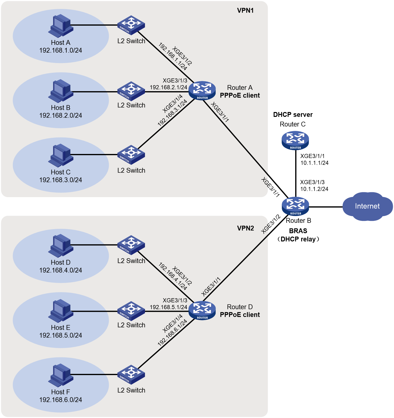
Analysis
Router A and Router D have three subnets attached as PPPoE clients. Users on each subnet are dual-stack users. Plan the IPv4 protocol stack and IPv6 protocol stack as follows:
· IPv4:
Create separate DHCP address pools for the three subnets. Configure the gateway address for a DHCP address pool of a subnet as the IP address of the interface connecting to users on the subnet. In this way, when a user on the interface comes online, the user can obtain the corresponding DHCP address pool based on the interface IP for allocating an IP address to the user.
· IPv6:
The PD prefix pool that a PPPoE client requests from the PPPoE server cannot be directly used by multiple subnets. Configure the following settings:
Ignore the PD prefixes allocated by the PPPoE server. Select the corresponding prefixes from the range of 240E:390:CDD:15B0::/64 to 240E:390:CDD:15BF::/64 according to the number of subnets. As a best practice, configure the prefixes in the ascending order. In this way, the PPPoE client can automatically allocate to each subnet the actual prefixes obtained from the service provider.
In this example, Ten-GigabitEthernet 3/1/2 through Ten-GigabitEthernet 3/1/4 of Router A are configured with the following prefixes:
¡ On Ten-GigabitEthernet 3/1/2, execute the ipv6 address 1 240E:390:CDD:15B0::1/64 command.
¡ On Ten-GigabitEthernet 3/1/3, execute the ipv6 address 1 240E:390:CDD:15B1::1/64 command.
¡ On Ten-GigabitEthernet 3/1/4, execute the ipv6 address 1 240E:390:CDD:15B2::1/64 command.
In this example, Ten-GigabitEthernet 3/1/2 through Ten-GigabitEthernet 3/1/4 of Router D are configured with the following prefixes:
¡ On Ten-GigabitEthernet 3/1/2, execute the ipv6 address 1 240E:390:CDD:15B3::1/64 command.
¡ On Ten-GigabitEthernet 3/1/3, execute the ipv6 address 1 240E:390:CDD:15B4::1/64 command.
¡ On Ten-GigabitEthernet 3/1/4, execute the ipv6 address 1 240E:390:CDD:15B5::1/64 command.
Restrictions and guidelines
This device can act only as a PPPoE server and cannot act as a PPPoE client. The PPPoE client configuration provided in this example is for illustration only. For more information about PPPoE client configuration, see the corresponding product's configuration guides.
As a best practice, configure the MTU as 1494 and TCP MSS as 1472 for interface Dialer 1. If the maximum TCP MSS supported by the device is smaller than 1472, set the TCP MSS to the maximum value supported by the device as a best practice. If the dialup access speed or network access speed is slow, you can lower the values slightly.
Procedures
Configuring Router C (DHCP server)
# Enable DHCP.
<RouterC> system-view
[RouterC] dhcp enable
# Create IP address pool vpn1_pool, and configure the IP subnet, gateway address, and DNS server address for DHCP clients.
[RouterC] ip pool vpn1_pool
[RouterC-ip-pool-vpn1_pool] network 1.1.1.0 24
[RouterC-ip-pool-vpn1_pool] gateway-list 1.1.1.1
[RouterC-ip-pool-vpn1_pool] dns-list 8.8.8.8
# Exclude IP address 1.1.1.1 from dynamic allocation.
[RouterC-ip-pool-vpn1_pool] forbidden-ip 1.1.1.1
[RouterC-ip-pool-vpn1_pool] quit
# Create IP address pool vpn2_pool, and configure the IP subnet, gateway address, and DNS server address for DHCP clients.
[RouterC] ip pool vpn2_pool
[RouterC-ip-pool-vpn2_pool] network 2.2.2.0 24
[RouterC-ip-pool-vpn2_pool] gateway-list 2.2.2.1
[RouterC-ip-pool-vpn2_pool] dns-list 8.8.8.8
# Exclude IP address 2.2.2.1 from dynamic allocation.
[RouterC-ip-pool-vpn2_pool] forbidden-ip 2.2.2.1
[RouterC-ip-pool-vpn2_pool] quit
# Configure a static route to the PPPoE server.
[RouterC] ip route-static 1.1.1.0 24 10.1.1.2
[RouterC] ip route-static 2.2.2.0 24 10.1.1.2
Configuring Router B (PPPoE server)
1. Configure VT interfaces:
# Configure Virtual-Template 1 to use CHAP for authenticating the peer.
<RouterB> system-view
[RouterB] interface virtual-template 1
[RouterB-Virtual-Template1] ppp authentication-mode chap domain default enable dm1
# Disable RA message suppression.
[RouterB-Virtual-Template1] undo ipv6 nd ra halt
[RouterB-Virtual-Template1] quit
# Configure Virtual-Template 2 to use CHAP for authenticating the peer.
<RouterB> system-view
[RouterB] interface virtual-template 2
[RouterB-Virtual-Template2] ppp authentication-mode chap domain default enable dm2
# Disable RA message suppression.
[RouterB-Virtual-Template2] undo ipv6 nd ra halt
[RouterB-Virtual-Template2] quit
2. Create VPN instances:
# Create VPN instance vpn1.
[RouterB] ip vpn-instance vpn1
[RouterB-vpn-instance-vpn1] quit
# Create VPN instance vpn2.
[RouterB] ip vpn-instance vpn2
[RouterB-vpn-instance-vpn2] quit
3. Configure the address pools:
# Enable DHCP.
[RouterB] dhcp enable
# Create remote BAS IP address pool vpn1_pool, and specify the gateway address, excluded IP address 1.1.1.1, DHCP server, and a VPN instance for the address pool.
[RouterB] ip pool vpn1_pool bas remote
[RouterB-ip-pool-vpn1_pool] gateway 1.1.1.1 24
[RouterB-ip-pool-vpn1_pool] forbidden-ip 1.1.1.1
[RouterB-ip-pool-vpn1_pool] remote-server 10.1.1.1
[RouterB-ip-pool-vpn1_pool] vpn-instance vpn1
[RouterB-ip-pool-vpn1_pool] quit
# Create remote BAS IP address pool vpn2_pool, and specify the gateway address, excluded IP address 2.2.2.1, DHCP server, and a VPN instance for the address pool.
[RouterB] ip pool vpn2_pool bas remote
[RouterB-ip-pool-vpn2_pool] gateway 2.2.2.1 24
[RouterB-ip-pool-vpn2_pool] forbidden-ip 2.2.2.1
[RouterB-ip-pool-vpn2_pool] remote-server 10.1.1.1
[RouterB-ip-pool-vpn2_pool] vpn-instance vpn2
[RouterB-ip-pool-vpn2_pool] quit
# Automatically generate a link-local address on Ten-GigabitEthernet 3/1/1.
[RouterB] interface ten-gigabitethernet 3/1/1
[RouterB-Ten-GigabitEthernet3/1/1] ipv6 address auto link-local
# Disable RA message suppression.
[RouterB-Ten-GigabitEthernet3/1/1] undo ipv6 nd ra halt
# Enable the DHCPv4 relay agent on the interface.
[RouterB-Ten-GigabitEthernet3/1/1] dhcp select relay
# Enable the DHCPv6 server on the interface.
[RouterB-Ten-GigabitEthernet3/1/1] ipv6 dhcp select server
# Enable the PPPoE server and on Ten-GigabitEthernet 3/1/1, and bind it to Virtual-Template 1.
[RouterB-Ten-GigabitEthernet3/1/1] pppoe-server bind virtual-template 1
[RouterB-Ten-GigabitEthernet3/1/1] quit
¡ Use VPN1:
# (For NDRA.) Configure DHCPv6 prefix pool 1 that contains prefix 2003::/48, specify the length of prefixes to be assigned as 64, and bind it to VPN instance vpn1.
[RouterB] ipv6 dhcp prefix-pool 1 prefix 2003::/48 assign-len 64 vpn-instance vpn1
# Create IPv6 address pool vpn1_ndra, reference prefix pool 1, and bind it to VPN instance vpn1.
[RouterB] ipv6 pool vpn1_ndra
[RouterB-ipv6-pool-vpn1_ndra] prefix-pool 1 export-route
[RouterB-ipv6-pool-vpn1_ndra] vpn-instance vpn1
[RouterB-ipv6-pool-vpn1_ndra] quit
# (For IA_PD.) Configure DHCPv6 prefix pool 6 that contains prefix 4001::/32, specify the length of prefixes to be assigned as 42, and bind it to VPN instance vpn1.
[RouterB] ipv6 dhcp prefix-pool 6 prefix 4001::/32 assign-len 42 vpn-instance vpn1
# Create IPv6 address pool vpn1_iapd, reference prefix pool 6, and bind it to VPN instance vpn1.
[RouterB] ipv6 pool vpn1_iapd
[RouterB-ipv6-pool-vpn1_iapd] prefix-pool 6 export-route
[RouterB-ipv6-pool-vpn1_iapd] vpn-instance vpn1
[RouterB-ipv6-pool-vpn1_iapd] quit
¡ Use VPN2:
# (For NDRA.) Configure DHCPv6 prefix pool 1 that contains prefix 3003::/48, specify the length of prefixes to be assigned as 64, and bind it to VPN instance vpn2.
[RouterB] ipv6 dhcp prefix-pool 1 prefix 3003::/48 assign-len 64 vpn-instance vpn2
# Create IPv6 address pool vpn2_ndra, reference prefix pool 1, and bind it to VPN instance vpn2.
[RouterB] ipv6 pool vpn2_ndra
[RouterB-ipv6-pool-vpn2_ndra] prefix-pool 1 export-route
[RouterB-ipv6-pool-vpn2_ndra] vpn-instance vpn2
[RouterB-ipv6-pool-vpn2_ndra] quit
# (For IA_PD.) Configure DHCPv6 prefix pool 6 that contains prefix 5001::/32, specify the length of prefixes to be assigned as 42, and bind it to VPN instance vpn2.
[RouterB] ipv6 dhcp prefix-pool 6 prefix 5001::/32 assign-len 42 vpn-instance vpn2
# Create IPv6 address pool vpn2_iapd, reference prefix pool 6, and bind it to VPN instance vpn2.
[RouterB] ipv6 pool vpn2_iapd
[RouterB-ipv6-pool-vpn2_iapd] prefix-pool 6 export-route
[RouterB-ipv6-pool-vpn2_iapd] vpn-instance vpn2
[RouterB-ipv6-pool-vpn2_iapd] quit
4. Configure a local user and authentication domains:
# Configure a PPPoE user.
[RouterB] local-user user1 class network
[RouterB-luser-network-user1] password simple 123456TESTplat&!
[RouterB-luser-network-user1] service-type ppp
[RouterB-luser-network-user1] quit
# (For vpn1.) In an ISP domain, configure local AAA for users and authorize an IP address pool, ND prefix pool, IPv6 DNS server address, address pool, and VPN instance.
[RouterB] domain name dm1
[RouterB-isp-dm1] authentication ppp local
[RouterB-isp-dm1] accounting ppp local
[RouterB-isp-dm1] authorization ppp local
[RouterB-isp-dm1] authorization-attribute ip-pool vpn1_pool
[RouterB-isp-dm1] authorization-attribute ipv6-nd-prefix-pool vpn1_ndra
[RouterB-isp-dm1] authorization-attribute primary-dns ipv6 8::8
[RouterB-isp-dm1] authorization-attribute ipv6-pool vpn1_iapd
[RouterB-isp-dm1] authorization-attribute vpn-instance vpn1
[RouterB-isp-dm1] quit
# (For vpn2.) In an ISP domain, configure local AAA for users and authorize an IP address pool, ND prefix pool, IPv6 DNS server address, address pool, and VPN instance.
[RouterB] domain name dm2
[RouterB-isp-dm2] authentication ppp local
[RouterB-isp-dm2] accounting ppp local
[RouterB-isp-dm2] authorization ppp local
[RouterB-isp-dm2] authorization-attribute ip-pool vpn2_pool
[RouterB-isp-dm2] authorization-attribute ipv6-nd-prefix-pool vpn2_ndra
[RouterB-isp-dm2] authorization-attribute primary-dns ipv6 8::8
[RouterB-isp-dm2] authorization-attribute ipv6-pool vpn2_iapd
[RouterB-isp-dm2] authorization-attribute vpn-instance vpn2
[RouterB-isp-dm2] quit
5. Configure PBR policies:
|
|
NOTE: To ensure traffic forwarding between VPNs, you must configure static routes and policy-based routes. |
a. Configure static routes to forward traffic in the DHCP request direction in VPN instances vpn1 and vpn2 to the DHCP server.
[RouterB] ip route-static vpn-instance vpn1 10.1.1.0 24 10.1.1.1 public
[RouterB] ip route-static vpn-instance vpn2 10.1.1.0 24 10.1.1.1 public
b. Configure PBR to forward the response traffic from the DHCP server to the VPN instances of DHCP clients:
# Create ACL 3000 to match packets destined to network segment 1.1.1.0/24.
[RouterB] acl advanced 3000
[RouterB-acl-ipv4-adv-3000] rule 0 permit ip destination 1.1.1.0 0.0.0.255
[RouterB-acl-ipv4-adv-3000] quit
# Create ACL 3010 to match packets destined to network segment 2.2.2.0/24.
[RouterB] acl advanced 3010
[RouterB-acl-ipv4-adv-3010] rule 0 permit ip destination 2.2.2.0 0.0.0.255
[RouterB-acl-ipv4-adv-3010] quit
# Create PBR policy named dhcp_to_bras, and configure permit-mode node 0 in the policy to forward packets matching ACL 3000 in VPN instance vpn1.
[RouterB] policy-based-route dhcp_to_bras permit node 0
[RouterB-pbr-dhcp_to_bras-0] if-match acl 3000
[RouterB-pbr-dhcp_to_bras-0] apply access-vpn vpn-instance vpn1
[RouterB-pbr-dhcp_to_bras-0] quit
# Create PBR policy named dhcp_to_bras, and configure permit-mode node 10 in the policy to forward packets matching ACL 3010 in VPN instance vpn2.
[RouterB] policy-based-route dhcp_to_bras permit node 10
[RouterB-pbr-dhcp_to_bras-10] if-match acl 3010
[RouterB-pbr-dhcp_to_bras-10] apply access-vpn vpn-instance vpn2
[RouterB-pbr-dhcp_to_bras-10] quit
# Apply policy dhcp_to_bras to Ten-GigabitEthernet 3/1/3, which is connected to the DHCP server.
[RouterB] interface ten-gigabitethernet 3/1/3
[RouterB–Ten-GigabitEthernet3/1/3] ip policy-based-route dhcp_to_bras
[RouterB–Ten-GigabitEthernet3/1/3] quit
Configuring Router A (PPPoE client)
# Enable bundle DDR on interface Dialer 1.
<RouterA> system-view
[RouterA] interface dialer 1
[RouterA-Dialer1] dialer bundle enable
# Configure the username and password for CHAP authentication on Router A.
[RouterA-Dialer1] ppp chap user user1
[RouterA-Dialer1] ppp chap password simple 123456TESTplat&!
# Configure the PPPoE client to operate in permanent mode.
[RouterA-Dialer1] dialer timer idle 0
# Configure the auto-dial timer as 60 seconds for DDR.
[RouterA-Dialer1] dialer timer autodial 60
# Configure the MTU and TCP MSS for interface Dialer 1. If the maximum TCP MSS supported by the device is smaller than 1472, set the TCP MSS to the maximum value supported by the device as a best practice.
[RouterA-Dialer1] mtu 1494
[RouterA-Dialer1] tcp mss 1472
(For IPv4.) Configure interface Dialer 1 to obtain an IPv4 address through PPP negotiation. Configure interface Dialer 1 to actively request the DNS server IP address from its peer and accept the DNS server IP addresses assigned by the peer.
[RouterA-Dialer1] ip address ppp-negotiate
[RouterA-Dialer1] ppp ipcp dns request
[RouterA-Dialer1] ppp ipcp dns admit-any
# (For IPv4.) Translate the source addresses of the packets from internal hosts into the IP address of interface Dialer 1.
[RouterA-Dialer1] nat outbound
# (For NDRA.) Configure interface Dialer 1 to automatically generate an IPv6 global unicast address.
[RouterA-Dialer1] ipv6 address auto
# (For IA_PD.) Configure interface Dialer 1 to use DHCPv6 to obtain an IPv6 address and other configuration parameters.
[RouterA-Dialer1] ipv6 address dhcp-alloc
# (For IA_PD.) Configure interface Dialer 1 as a DHCPv6 client for IPv6 prefix acquisition. Configure the DHCPv6 client to assign ID 1 to the obtained IPv6 prefix.
[RouterA-Dialer1] ipv6 dhcp client pd 1
[RouterA-Dialer1] quit
# Configure a PPPoE session and specify dialer bundle 1 (which corresponds to interface Dialer 1) for the session.
[RouterA] interface ten-gigabitethernet 3/1/1
[RouterA-Ten-GigabitEthernet3/1/1] pppoe-client dial-bundle-number 1
[RouterA-Ten-GigabitEthernet3/1/1] quit
# Configure the default route.
[RouterA] ip route-static 0.0.0.0 0 dialer 1
[RouterA] ipv6 route-static :: 0 dialer 1
# Enable DHCP.
[RouterA] dhcp enable
# Configure DHCP address pool pool1 to allocate private IPv4 addresses to internal network users.
[RouterA] dhcp server ip-pool pool1
[RouterA-dhcp-pool-pool1] network 192.168.1.0 24
[RouterA-dhcp-pool-pool1] gateway-list 192.168.1.1
[RouterA-dhcp-pool-pool1] dns-list 8.8.8.8
# Exclude IP address 192.168.1.1 from dynamic allocation.
[RouterA-dhcp-pool-pool1] forbidden-ip 192.168.1.1
[RouterA-dhcp-pool-pool1] quit
# Configure DHCP address pool pool2 to allocate private IPv4 addresses to internal network users.
[RouterA] dhcp server ip-pool pool2
[RouterA-dhcp-pool-pool2] network 192.168.2.0 24
[RouterA-dhcp-pool-pool2] gateway-list 192.168.2.1
[RouterA-dhcp-pool-pool2] dns-list 8.8.8.8
# Exclude IP address 192.168.2.1 from dynamic allocation.
[RouterA-dhcp-pool-pool2] forbidden-ip 192.168.2.1
[RouterA-dhcp-pool-pool2] quit
# Configure DHCP address pool pool3 to allocate private IPv4 addresses to internal network users.
[RouterA] dhcp server ip-pool pool3
[RouterA-dhcp-pool-pool3] network 192.168.3.0 24
[RouterA-dhcp-pool-pool3] gateway-list 192.168.3.1
[RouterA-dhcp-pool-pool3] dns-list 8.8.8.8
# Exclude IP address 192.168.3.1 from dynamic allocation.
[RouterA-dhcp-pool-pool3] forbidden-ip 192.168.3.1
[RouterA-dhcp-pool-pool3] quit
# Assign the IPv4 gateway address of internal network users to Ten-GigabitEthernet 3/1/2.
[RouterA] interface ten-gigabitethernet 3/1/2
[RouterA-Ten-GigabitEthernet3/1/2] ip address 192.168.1.1 24
# Disable RA message suppression on Ten-GigabitEthernet 3/1/2.
[RouterA-Ten-GigabitEthernet3/1/2] undo ipv6 nd ra halt
# Configure Ten-GigabitEthernet 3/1/2 to dynamically obtain IPv6 prefix 1 (use IPv6 prefix 1 to generate an IPv6 address) and advertise IPv6 prefix 1 to endpoints through RA messages.
[RouterA-Ten-GigabitEthernet3/1/2] ipv6 address 1 240E:390:CDD:15B0::1/64
[RouterA-Ten-GigabitEthernet3/1/2] quit
# Assign the IPv4 gateway address of internal network users to Ten-GigabitEthernet 3/1/3.
[RouterA] interface ten-gigabitethernet 3/1/3
[RouterA-Ten-GigabitEthernet3/1/3] ip address 192.168.2.1 24
# Disable RA message suppression on Ten-GigabitEthernet 3/1/3.
[RouterA-Ten-GigabitEthernet3/1/3] undo ipv6 nd ra halt
# Configure Ten-GigabitEthernet 3/1/3 to dynamically obtain IPv6 prefix 1 (use IPv6 prefix 1 to generate an IPv6 address) and advertise IPv6 prefix 1 to endpoints through RA messages.
[RouterA-Ten-GigabitEthernet3/1/3] ipv6 address 1 240E:390:CDD:15B1::1/64
[RouterA-Ten-GigabitEthernet3/1/3] quit
# Assign the IPv4 gateway address of internal network users to Ten-GigabitEthernet 3/1/4.
[RouterA] interface ten-gigabitethernet 3/1/4
[RouterA-Ten-GigabitEthernet3/1/4] ip address 192.168.3.1 24
# Disable RA message suppression on Ten-GigabitEthernet 3/1/4.
[RouterA-Ten-GigabitEthernet3/1/4] undo ipv6 nd ra halt
# Configure Ten-GigabitEthernet 3/1/4 to dynamically obtain IPv6 prefix 1 (use IPv6 prefix 1 to generate an IPv6 address) and advertise IPv6 prefix 1 to endpoints through RA messages.
[RouterA-Ten-GigabitEthernet3/1/4] ipv6 address 1 240E:390:CDD:15B2::1/64
[RouterA-Ten-GigabitEthernet3/1/4] quit
Configuring Router D (PPPoE client)
# Enable bundle DDR on interface Dialer 1.
<RouterD> system-view
[RouterD] interface dialer 1
[RouterD-Dialer1] dialer bundle enable
# Configure the username and password for CHAP authentication on Router D.
[RouterD-Dialer1] ppp chap user user1
[RouterD-Dialer1] ppp chap password simple 123456TESTplat&!
# Configure the PPPoE client to operate in permanent mode.
[RouterD-Dialer1] dialer timer idle 0
# Configure the auto-dial timer as 60 seconds for DDR.
[RouterD-Dialer1] dialer timer autodial 60
# Configure the MTU and TCP MSS for interface Dialer 1. If the maximum TCP MSS supported by the device is smaller than 1472, set the TCP MSS to the maximum value supported by the device as a best practice.
[RouterD-Dialer1] mtu 1494
[RouterD-Dialer1] tcp mss 1472
(For IPv4.) Configure interface Dialer 1 to obtain an IPv4 address through PPP negotiation. Configure interface Dialer 1 to actively request the DNS server IP address from its peer and accept the DNS server IP addresses assigned by the peer.
[RouterD-Dialer1] ip address ppp-negotiate
[RouterD-Dialer1] ppp ipcp dns request
[RouterD-Dialer1] ppp ipcp dns admit-any
# (For IPv4.) Translate the source addresses of the packets from internal hosts into the IP address of interface Dialer 1.
[RouterD-Dialer1] nat outbound
# (For NDRA.) Configure interface Dialer 1 to automatically generate an IPv6 global unicast address.
[RouterD-Dialer1] ipv6 address auto
# (For IA_PD.) Configure interface Dialer 1 to use DHCPv6 to obtain an IPv6 address and other configuration parameters.
[RouterD-Dialer1] ipv6 address dhcp-alloc
# (For IA_PD.) Configure interface Dialer 1 as a DHCPv6 client for IPv6 prefix acquisition. Configure the DHCPv6 client to assign ID 1 to the obtained IPv6 prefix.
[RouterD-Dialer1] ipv6 dhcp client pd 1
[RouterD-Dialer1] quit
# Configure a PPPoE session and specify dialer bundle 1 (which corresponds to interface Dialer 1) for the session.
[RouterD] interface ten-gigabitethernet 3/1/1
[RouterD-Ten-GigabitEthernet3/1/1] pppoe-client dial-bundle-number 1
[RouterD-Ten-GigabitEthernet3/1/1] quit
# Configure the default route.
[RouterD] ip route-static 0.0.0.0 0 dialer 1
[RouterD] ipv6 route-static :: 0 dialer 1
# Enable DHCP.
[RouterD] dhcp enable
# Configure DHCP address pool pool1 to allocate private IPv4 addresses to internal network users.
[RouterD] dhcp server ip-pool pool1
[RouterD-dhcp-pool-pool1] network 192.168.4.0 24
[RouterD-dhcp-pool-pool1] gateway-list 192.168.4.1
[RouterD-dhcp-pool-pool1] dns-list 8.8.8.8
# Exclude IP address 192.168.4.1 from dynamic allocation.
[RouterD-dhcp-pool-pool1] forbidden-ip 192.168.4.1
[RouterD-dhcp-pool-pool1] quit
# Configure DHCP address pool pool2 to allocate private IPv4 addresses to internal network users.
[RouterD] dhcp server ip-pool pool2
[RouterD-dhcp-pool-pool2] network 192.168.5.0 24
[RouterD-dhcp-pool-pool2] gateway-list 192.168.5.1
[RouterD-dhcp-pool-pool2] dns-list 8.8.8.8
# Exclude IP address 192.168.5.1 from dynamic allocation.
[RouterD-dhcp-pool-pool2] forbidden-ip 192.168.5.1
[RouterD-dhcp-pool-pool2] quit
# Configure DHCP address pool pool3 to allocate private IPv4 addresses to internal network users.
[RouterD] dhcp server ip-pool pool3
[RouterD-dhcp-pool-pool3] network 192.168.6.0 24
[RouterD-dhcp-pool-pool3] gateway-list 192.168.6.1
[RouterD-dhcp-pool-pool3] dns-list 8.8.8.8
# Exclude IP address 192.168.6.1 from dynamic allocation.
[RouterD-dhcp-pool-pool3] forbidden-ip 192.168.6.1
[RouterD-dhcp-pool-pool3] quit
# Assign the IPv4 gateway address of internal network users to Ten-GigabitEthernet 3/1/2.
[RouterD] interface ten-gigabitethernet 3/1/2
[RouterD-Ten-GigabitEthernet3/1/2] ip address 192.168.4.1 24
# Disable RA message suppression on Ten-GigabitEthernet 3/1/2.
[RouterD-Ten-GigabitEthernet3/1/2] undo ipv6 nd ra halt
# Configure Ten-GigabitEthernet 3/1/2 to dynamically obtain IPv6 prefix 1 (use IPv6 prefix 1 to generate an IPv6 address) and advertise IPv6 prefix 1 to endpoints through RA messages.
[RouterD-Ten-GigabitEthernet3/1/2] ipv6 address 1 240E:390:CDD:15B4::1/64
[RouterD-Ten-GigabitEthernet3/1/2] quit
# Assign the IPv4 gateway address of internal network users to Ten-GigabitEthernet 3/1/3.
[RouterD] interface ten-gigabitethernet 3/1/3
[RouterD-Ten-GigabitEthernet3/1/3] ip address 192.168.5.1 24
# Disable RA message suppression on Ten-GigabitEthernet 3/1/3.
[RouterD-Ten-GigabitEthernet3/1/3] undo ipv6 nd ra halt
# Configure Ten-GigabitEthernet 3/1/3 to dynamically obtain IPv6 prefix 1 (use IPv6 prefix 1 to generate an IPv6 address) and advertise IPv6 prefix 1 to endpoints through RA messages.
[RouterD-Ten-GigabitEthernet3/1/3] ipv6 address 1 240E:390:CDD:15B5::1/64
[RouterD-Ten-GigabitEthernet3/1/3] quit
# Assign the IPv4 gateway address of internal network users to Ten-GigabitEthernet 3/1/4.
[RouterD] interface ten-gigabitethernet 3/1/4
[RouterD-Ten-GigabitEthernet3/1/4] ip address 192.168.6.1 24
# Disable RA message suppression on Ten-GigabitEthernet 3/1/4.
[RouterD-Ten-GigabitEthernet3/1/4] undo ipv6 nd ra halt
# Configure Ten-GigabitEthernet 3/1/4 to dynamically obtain IPv6 prefix 1 (use IPv6 prefix 1 to generate an IPv6 address) and advertise IPv6 prefix 1 to endpoints through RA messages.
[RouterD-Ten-GigabitEthernet3/1/4] ipv6 address 1 240E:390:CDD:15B6::1/64
[RouterD-Ten-GigabitEthernet3/1/4] quit
Verifying the configuration
After the configuration is completed, Router A as an example uses username user1 and password 123456TESTplat&! to access Router B through PPPoE. Then, Router B obtains an IPv4 address through DHCPv4, and uses the assigned IPv6 prefix and the IPv6 interface ID obtained through IPv6CP negotiation to automatically generate an IPv6 global unicast address.
[RouterB] display access-user interface ten-gigabitethernet 3/1/1 vpn-instance vpn1
UserID Interface IP address MAC address S-/C-VLAN
Username Access type
IPv6 address
0x6 XGE3/1/1 1.1.1.2 2e65-0e78-0406 -/-
user1 PPPoE
2003::2E65:E78:400:8C
# Display binding information for the assigned IPv6 prefixes.
[RouterB] display ipv6 dhcp server pd-in-use vpn-instance vpn1
Pool: vpn1_iapd
IPv6 prefix Type Lease expiration DUID
4001::/42 Auto(C) Mar 10 10:22:02 2022 052e650e780406
Pool: vpn1_ndra
IPv6 prefix Type Lease expiration DUID
2003::/64 Auto(C) Expires after 2100 00326536352e30653738
2e303430362d66666666
66666666
The output shows that Router B assigns PD prefix 4001::/ 42 to Router A through DHCPv6.
# Display the DHCPv6 client information of interface Dialer 1 on Router A.
[RouterA] display ipv6 dhcp client interface Dialer 1
Dialer1:
Type: Stateless client
State: IDLE
Client DUID: 000300012e650e780400
Type: Stateful client requesting prefix
State: OPEN
Client DUID: 000300012e650e780400
Preferred server:
Reachable via address: FE80::3860:E0FF:FE34:206
Server DUID: 000300013a60e0340200
IA_PD: IAID 0x00000001, T1 302400 sec, T2 483840 sec
Prefix: 4001::/42
Preferred lifetime 604800 sec, valid lifetime 2592000 sec
Will expire on Mar 10 2022 at 10:22:03 (2590873 seconds left)
DNS server addresses:
8::8
Type: Stateful client requesting address
State: SOLICIT
Client DUID: 000300012e650e780400
The output shows that Router A obtains PD prefix 4001::/ 42 from Router B through DHCPv6.
# Display information about IPv6 prefixes created on Router A.
[RouterA] display ipv6 prefix
Number Prefix Type
1 4001::/42 Dynamic
The output shows that:
· After Router A obtains a PD prefix from Router B, Router A creates an IPv6 prefix with ID 1 according to the ipv6 dhcp client pd 1 command configuration.
· Then, Router A assigns PD prefix 4001::/42 to hosts, and hosts use the PD prefix to generate IPv6 global unicast addresses.
# Display brief IPv6 configuration for Layer 3 interfaces on Router A.
[RouterA] display ipv6 interface brief
*down: administratively down
(s): spoofing
Interface Physical Protocol IPv6 Address
Dialer1 up up 2003::2E65:E78:400:8C
Ten-GigabitEthernet3/1/1 up up Unassigned
Ten-GigabitEthernet3/1/2 up up 4001:0:1D:15B0::1
Ten-GigabitEthernet3/1/3 up up 4001:0:1D:15B1::1
Ten-GigabitEthernet3/1/4 up up 4001:0:1D:15B2::1
……
The output shows that:
· Interface Dialer 1 of Router A has obtained an IPv6 address prefix from Router B through NDRA and uses the prefix to generate an IPv6 address.
· Interfaces Ten-GigabitEthernet 3/1/2 through Ten-GigabitEthernet 3/1/4 use IPv6 prefix 1 to generate their IPv6 addresses.
# Display brief IP configuration for Layer 3 interfaces on Router A.
[RouterA] display ip interface brief
*down: administratively down
(s): spoofing (l): loopback
Interface Physical Protocol IP address/Mask VPN instance Description
Dia1 up up 1.1.1.2/32 -- --
XGE3/1/1 up up -- -- --
XGE3/1/2 up up 192.168.1.1/24 -- --
XGE3/1/3 up up 192.168.2.1/24 -- --
XGE3/1/4 up up 192.168.3.1/24 -- --
……
The output shows that interface Dialer 1 of Router A has obtained an IPv4 address from Router B through DHCP.
Configuration files
· Router C (DHCP server):
#
dhcp enable
#
ip pool vpn1_pool
gateway-list 1.1.1.1
network 1.1.1.0 mask 255.255.255.0
dns-list 8.8.8.8
forbidden-ip 1.1.1.1
#
ip pool vpn2_pool
gateway-list 2.2.2.1
network 2.2.2.0 mask 255.255.255.0
dns-list 8.8.8.8
forbidden-ip 2.2.2.1
#
interface Ten-GigabitEthernet3/1/1
ip address 10.1.1.1 255.255.255.0
#
ip route-static 1.1.1.0 24 10.1.1.2
ip route-static 2.2.2.0 24 10.1.1.2
#
· Router B (PPPoE server)
#
ip vpn-instance vpn1
#
ip vpn-instance vpn2
#
dhcp enable
#
ipv6 dhcp prefix-pool 1 prefix 2003::/48 assign-len 64 vpn-instance vpn1
ipv6 dhcp prefix-pool 1 prefix 3003::/48 assign-len 64 vpn-instance vpn2
ipv6 dhcp prefix-pool 6 prefix 4001::/32 assign-len 42 vpn-instance vpn1
ipv6 dhcp prefix-pool 6 prefix 5001::/32 assign-len 42 vpn-instance vpn2
#
ip pool vpn1_pool bas remote
vpn-instance vpn1
gateway 1.1.1.1 mask 255.255.255.0
forbidden-ip 1.1.1.1
remote-server 10.1.1.1
#
ip pool vpn2_pool bas remote
vpn-instance vpn2
gateway 2.2.2.1 mask 255.255.255.0
forbidden-ip 2.2.2.1
remote-server 10.1.1.1
#
ipv6 pool vpn1_iapd
vpn-instance vpn1
prefix-pool 6 export-route
#
ipv6 pool vpn1_ndra
vpn-instance vpn1
prefix-pool 1 export-route
#
ipv6 pool vpn2_iapd
vpn-instance vpn2
prefix-pool 6 export-route
#
ipv6 pool vpn2_ndra
vpn-instance vpn2
prefix-pool 1 export-route
#
policy-based-route dhcp_to_bras permit node 0
if-match acl 3000
apply access-vpn vpn-instance vpn1
#
policy-based-route dhcp_to_bras permit node 10
if-match acl 3010
apply access-vpn vpn-instance vpn2
#
interface Virtual-Template1
ppp authentication-mode chap domain default enable dm1
undo ipv6 nd ra halt
#
interface Virtual-Template2
ppp authentication-mode chap domain default enable dm2
undo ipv6 nd ra halt
#
interface Ten-GigabitEthernet3/1/1
dhcp select relay
ipv6 dhcp select server
ipv6 address auto link-local
undo ipv6 nd ra halt
pppoe-server bind virtual-template 1
#
interface Ten-GigabitEthernet3/1/2
dhcp select relay
ipv6 dhcp select server
ipv6 address auto link-local
undo ipv6 nd ra halt
pppoe-server bind virtual-template 2
#
interface Ten-GigabitEthernet3/1/3
ip address 10.1.1.2 255.255.255.0
ip policy-based-route dhcp_to_bras
#
ip route-static vpn-instance vpn1 10.1.1.0 24 10.1.1.1 public
ip route-static vpn-instance vpn2 10.1.1.0 24 10.1.1.1 public
#
acl advanced 3000
rule 5 permit ip destination 1.1.1.0 0.0.0.255
#
acl advanced 3010
rule 5 permit ip destination 2.2.2.0 0.0.0.255
#
domain name dm1
authorization-attribute ip-pool vpn1_pool
authorization-attribute ipv6-pool vpn1_iapd
authorization-attribute ipv6-nd-prefix-pool vpn1_ndra
authorization-attribute primary-dns ipv6 8::8
authorization-attribute vpn-instance vpn1
authentication ppp local
authorization ppp local
accounting ppp local
#
domain name dm2
authorization-attribute ip-pool vpn2_pool
authorization-attribute ipv6-pool vpn2_iapd
authorization-attribute ipv6-nd-prefix-pool vpn2_ndra
authorization-attribute primary-dns ipv6 8::8
authorization-attribute vpn-instance vpn2
authentication ppp local
authorization ppp local
accounting ppp local
#
local-user user1 class network
password cipher $c$3$YLXDDUrqn4bxLGKl6QodP07JXUCjAA==
service-type ppp
#
· Router A (PPPoE client):
#
dhcp enable
#
dhcp server ip-pool pool1
gateway-list 192.168.1.1
network 192.168.1.0 mask 255.255.255.0
dns-list 8.8.8.8
forbidden-ip 192.168.1.1
#
dhcp server ip-pool pool2
gateway-list 192.168.2.1
network 192.168.2.0 mask 255.255.255.0
dns-list 8.8.8.8
forbidden-ip 192.168.2.1
#
dhcp server ip-pool pool3
gateway-list 192.168.3.1
network 192.168.3.0 mask 255.255.255.0
dns-list 8.8.8.8
forbidden-ip 192.168.3.1
#
interface Dialer1
mtu 1494
tcp mss 1472
ppp chap password cipher $c$3$B+kybBKT3fBLJwdkjmBILOSiLSO81A==
ppp chap user spp
ppp ipcp dns admit-any
ppp ipcp dns request
dialer bundle enable
dialer timer idle 0
dialer timer autodial 60
ip address ppp-negotiate
nat outbound
ipv6 address auto
ipv6 address dhcp-alloc
ipv6 dhcp client pd 1
#
interface Ten-GigabitEthernet3/1/1
pppoe-client dial-bundle-number 1
#
interface Ten-GigabitEthernet3/1/2
ip address 192.168.1.1 255.255.255.0
ipv6 address 1 240E:390:CDD:15B0::1/64
undo ipv6 nd ra halt
#
interface Ten-GigabitEthernet3/1/3
ip address 192.168.2.1 255.255.255.0
ipv6 address 1 240E:390:CDD:15B1::1/64
undo ipv6 nd ra halt
#
interface Ten-GigabitEthernet3/1/4
ip address 192.168.3.1 255.255.255.0
ipv6 address 1 240E:390:CDD:15B2::1/64
undo ipv6 nd ra halt
#
ip route-static 0.0.0.0 0 Dialer1
ipv6 route-static :: 0 Dialer1
#
· Router D (PPPoE client):
#
dhcp enable
#
dhcp server ip-pool pool1
gateway-list 192.168.4.1
network 192.168.4.0 mask 255.255.255.0
dns-list 8.8.8.8
forbidden-ip 192.168.4.1
#
dhcp server ip-pool pool2
gateway-list 192.168.5.1
network 192.168.5.0 mask 255.255.255.0
dns-list 8.8.8.8
forbidden-ip 192.168.5.1
#
dhcp server ip-pool pool3
gateway-list 192.168.6.1
network 192.168.6.0 mask 255.255.255.0
dns-list 8.8.8.8
forbidden-ip 192.168.6.1
#
interface Dialer1
mtu 1494
tcp mss 1472
ppp chap password cipher $c$3$B+kybBKT3fBLJwdkjmBILOSiLSO81A==
ppp chap user spp
ppp ipcp dns admit-any
ppp ipcp dns request
dialer bundle enable
dialer timer idle 0
dialer timer autodial 60
ip address ppp-negotiate
nat outbound
ipv6 address auto
ipv6 address dhcp-alloc
ipv6 dhcp client pd 1
#
interface Ten-GigabitEthernet3/1/1
pppoe-client dial-bundle-number 1
#
interface Ten-GigabitEthernet3/1/2
ip address 192.168.4.1 255.255.255.0
ipv6 address 1 240E:390:CDD:15B4::1/64
undo ipv6 nd ra halt
#
interface Ten-GigabitEthernet3/1/3
ip address 192.168.5.1 255.255.255.0
ipv6 address 1 240E:390:CDD:15B5::1/64
undo ipv6 nd ra halt
#
interface Ten-GigabitEthernet3/1/4
ip address 192.168.6.1 255.255.255.0
ipv6 address 1 240E:390:CDD:15B6::1/64
undo ipv6 nd ra halt
#
ip route-static 0.0.0.0 0 Dialer1
ipv6 route-static :: 0 Dialer1
#
WLAN service configuration example (IPoE Web only, no NAT involved)
Wireless service (WLAN service) is a widely-deployed service in ISP networks, and its application scope will become more and more extensive in the IoT environment. Wireless service is mainly realized through IPoE Web, and under the premise of users accessing ISP Wi-Fi, only the authentication page pushed by the ISP is available for access before authentication. After authentication, user endpoints can go online in the Wi-Fi domain.
Network requirements
As shown in Figure 52, Router A serves as the BRAS device of the ISP to provide access services for the wireless endpoints. The wireless endpoints use IPoE Web for access. The network requirements are as follows:
· General requirements:
¡ The wireless endpoints use IPoE Web to access the BRAS device through the Layer 2 network.
¡ The BRAS device acts as a DHCP server to assign IP addresses to the wireless endpoints in the preauthentication domain.
¡ A server deployed with Srun software acts as the RADIUS server.
¡ Another server deployed with H3C iMC acts as the portal authentication server and portal Web server.
· AAA requirements:
¡ Adopt the non-authentication and non-accounting method in the preauthentication domain.
¡ Use RADIUS for authentication and accounting in the domain after authentication.
¡ Deploy a primary RADIUS server and a secondary RADIUS server for redundancy.
¡ Use interface Loopback 0 as the source interface for the BRAS device to send RADIUS packets.
¡ Enable the device to interpret the RADIUS class attribute (attribute 25) as CAR parameters.
¡ Enable the RADIUS attribute translation feature.
¡ Enable the device to allow users that encounter accounting-start failures to stay online for the post-authentication domain.
· Web server requirements:
¡ Deploy a primary Web server and a secondary Web server for redundancy.
¡ Use interface Loopback 0 as the source interface for the BRAS device to send Web authentication packets.
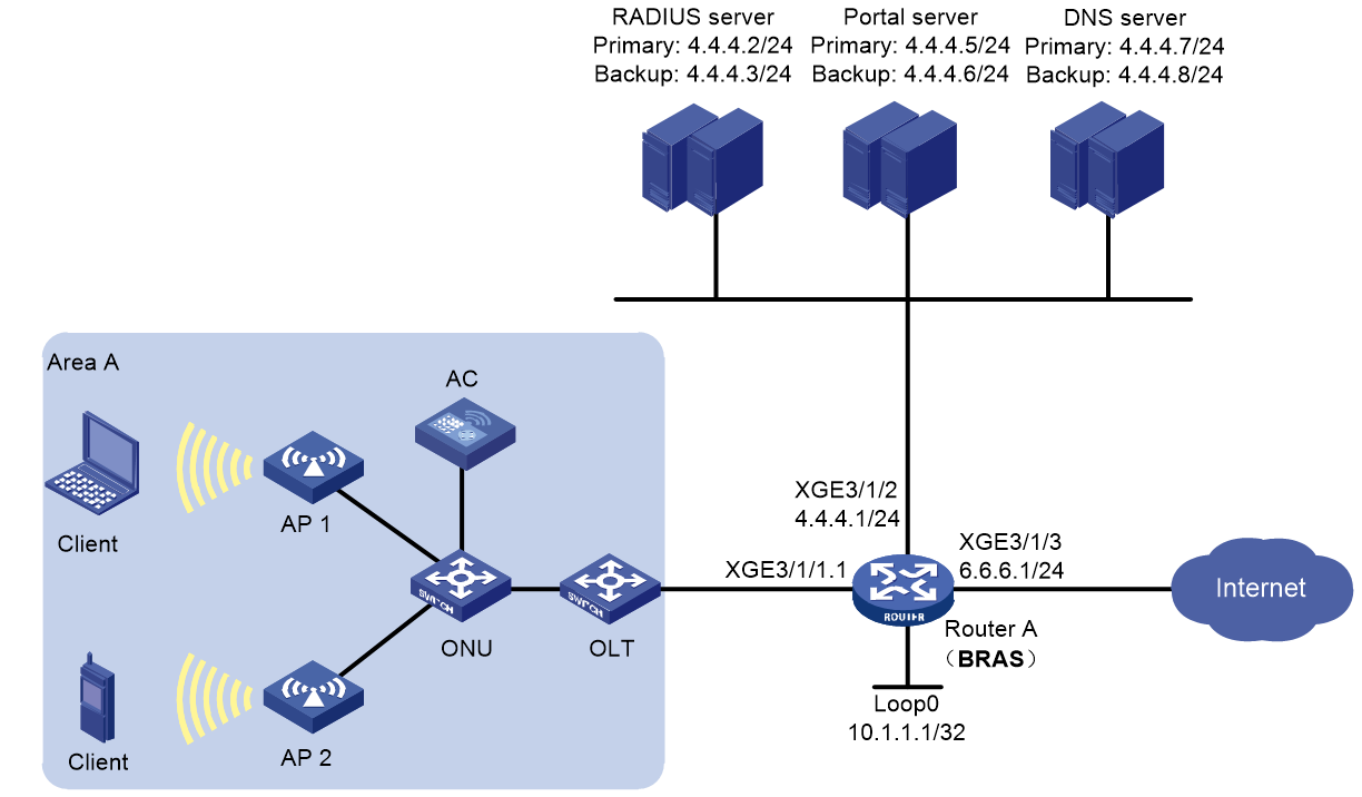
Analysis
· Configure the preauthentication domain to implement the following:
¡ After the wireless endpoint connects to the ISP's Wi-Fi, it obtains an IP address in the preauthentication domain (similar to the IPoE binding authentication process except for the configuration of direct IP address assignment without authentication in the domain).
¡ Enable the BRAS device to redirect wireless endpoint access to a specific URL to the Wi-Fi authentication page pushed by the ISP. After the user enters the account and password, the Portal server forwards the account and password to the BRAS device. The BRAS device then initiates authentication to the AAA server. After passing the authentication, the endpoint comes online in the Web authentication domain.
· Configure authorization address pool settings for the preauthentication domain. The Web authentication domain does not require authorization address pool configuration.
· Configure different user groups for the preauthentication domain and the Web authentication domain.
· For users in the preauthentication domain, configure QoS policy settings on the BRAS device to redirect the URLs accessed by the endpoints, and apply the redirection policy globally.
· (Optional.) In the wireless access scenario, you can verify SSIDs during user authentication through configuring the aaa ssid awifi command.
Procedure
Configuring IP addresses and routes
# Assign IPv4 address 4.4.4.1/24 and IPv6 address 4::1/64 to Ten-GigabitEthernet 3/1/2 on the BRAS.
<BRAS> system-view
[BRAS] interface ten-gigabitethernet 3/1/2
[BRAS-Ten-GigabitEthernet3/1/2] ip address 4.4.4.1 24
[BRAS-Ten-GigabitEthernet3/1/2] ipv6 address 4::1 64
[BRAS-Ten-GigabitEthernet3/1/2] quit
# Assign IPv4 address 6.6.6.1/24 and IPv6 address 6::1/64 to Ten-GigabitEthernet 3/1/3 on the BRAS.
[BRAS] interface ten-gigabitethernet 3/1/3
[BRAS-Ten-GigabitEthernet3/1/3] ip address 6.6.6.1 24
[BRAS-Ten-GigabitEthernet3/1/3] ipv6 address 6::1 64
[BRAS-Ten-GigabitEthernet3/1/3] quit
# Configure the static default route to the Internet.
[BRAS] ip route-static 0.0.0.0 0 6.1.1.2
[BRAS] ipv6 route-static :: 0 6::2
Configuring the DNS servers
In this example, Windows Server 2016 is used to describe the basic DNS server configuration. The configurations for the primary and secondary DNS servers are similar. This section uses the primary DNS server as an example. For information about configuring the log servers, see the corresponding software descriptions.
To configure a DNS server:
1. Install the DNS component:
a. Log in to the server, click Windows, and select Server Manager.
b. Click Add Roles and Features, and configure DNS.
c. On the Before you begin page, click Next.
d. On the Select installation type page, use the default option (Role-based or feature-based installation), and click Next.
e. On the Select destination server page, use the default option (Select a server from the server pool), and click Next.
f. On the Select server roles page, select DNS Server. On the Add Roles and Features Wizard page that opens, click Add Features, and then click Next.
g. On the Select features page, use the default settings, and click Next.
h. On the DNS Server page, click Next.
i. Click Install on the Confirm installation selections page and wait for the installation to complete.
j. Once installation completes, click Close to complete the installation of the DNS component.
2. Create an IPv4 forward lookup zone:
a. On the Server Manager page, click Tools, and select DNS.
b. Right-click Forward Lookup Zones on the DNS Manager page and select New Zone.
c. On the New Zone Wizard page, click Next.
d. On the Zone Type page, select Primary zone, and click Next.
e. On the Zone Name page, enter zone name ipv4.test.com.
f. On the Zone File page, use the default settings and click Next.
g. On the Dynamic Update page, select Do not allow dynamic updates and click Next.
h. On the New Zone Wizard page, click Finish.
i. On the DNS Manager page, click Forward Lookup Zones, right-click ipv4.test.com, and click New Host.
j. On the New Host page, enter host name www, enter IP address 4.4.4.7, and click Add Host.
The IPv4 forward lookup zone has been successfully created.
3. Create an IPv4 reverse lookup zone:
a. Right-click Reverse Lookup Zones on the DNS Manager page and select New Zone.
b. On the New Zone Wizard page, click Next.
c. On the Zone Type page, select Primary zone, and click Next.
d. On the Reverse Lookup Zone Name page, select IPv4 Reverse Lookup Zone, and click Next.
e. On the Reverse Lookup Zone Name page, enter network ID 4.4.4, and click Next.
f. On the Zone File page, use the default settings and click Next.
g. On the Dynamic Update page, select Do not allow dynamic updates and click Next.
h. On the New Zone Wizard page, click Finish.
i. On the DNS Manager page, click Reverse Lookup Zones, right-click 4.4.4.in-addr.arpa.dns, and click New Pointer.
j. On the New Resource Record page, enter host IP address 4.4.4.7, enter host name www.ipv4.test.com, and click OK.
The IPv4 reverse lookup zone has been successfully created.
4. Create an IPv6 forward lookup zone:
a. On the Server Manager page, click Tools, and select DNS.
b. Right-click Forward Lookup Zones on the DNS Manager page and select New Zone.
c. On the New Zone Wizard page, click Next.
d. On the Zone Type page, select Primary zone, and click Next.
e. On the Zone Name page, enter zone name ipv6.test.com.
f. On the Zone File page, use the default settings and click Next.
g. On the Dynamic Update page, select Do not allow dynamic updates and click Next.
h. On the New Zone Wizard page, click Finish.
i. On the DNS Manager page, click Forward Lookup Zones, right-click ipv6.test.com, and click New Host.
j. On the New Host page, enter host name www, enter IP address 4::7, and click Add Host.
The IPv6 forward lookup zone has been successfully created.
5. Create an IPv6 reverse lookup zone:
a. Right-click Reverse Lookup Zones on the DNS Manager page and select New Zone.
b. On the New Zone Wizard page, click Next.
c. On the Zone Type page, select Primary zone, and click Next.
d. On the Reverse Lookup Zone Name page, select IPv6 Reverse Lookup Zone, and click Next.
e. On the Reverse Lookup Zone Name page, enter network ID 4000:0000:0000:0000::/64, and click Next.
f. On the Zone File page, use the default settings and click Next.
g. On the Dynamic Update page, select Do not allow dynamic updates and click Next.
h. On the New Zone Wizard page, click Finish.
i. On the DNS Manager page, click Reverse Lookup Zones, right-click 0.0.0.0.0.0.0.0.0.0.0.0.0.0.0.4.in-addr.arpa.dns, and click New Pointer.
j. On the New Resource Record page, enter host IP address 4000.0000.0000.0000.0000.0000.0000.0007, enter host name www.ipv6.test.com, and click OK.
The IPv6 reverse lookup zone has been successfully created.
Configuring the BRAS device
1. Configure the DHCP server
# Enable DHCP globally.
<BRAS> system-view
[BRAS] dhcp enable
# Enable the DHCP server to return a DHCP-NAK message if the client notions of their IP addresses are incorrect.
[BRAS] dhcp server request-ip-address check
# Create a DHCP address pool named wlan_pool and enter its view.
[BRAS] ip pool wlan_pool bas local
# Specify 3.3.3.0/24 as the IP address range for dynamic allocation in the DHCP address pool.
[BRAS-ip-pool-wlan_pool] gateway 3.3.3.1 24
# Exclude IP address 3.3.3.1 from dynamic allocation in the DHCP address pool.
[BRAS-ip-pool-wlan_pool] forbidden-ip 3.3.3.1
# Specify DNS server addresses in the DHCP address pool.
[BRAS-ip-pool-wlan_pool] dns-list 4.4.4.7 4.4.4.8
[BRAS-ip-pool-wlan_pool] quit
2. Configure portal authentication servers
# Create the first portal authentication server named newpt01, specify its IP address as 4.4.4.5, and specify the key as 123456.
[BRAS] portal server newpt01
[BRAS-portal-server-newpt01] ip 4.4.4.5 key simple 123456
[BRAS-portal-server-newpt01] quit
# Create the second portal authentication server named newpt02, specify its IP address as 4.4.4.6, and specify the key as 123456.
[BRAS] portal server newpt02
[BRAS-portal-server-newpt02] ip 4.4.4.6 key simple 123456
[BRAS-portal-server-newpt02] quit
3. Specify the HTTPS redirect listening port number
# Specify the HTTPS redirect listening port number. (To avoid port conflict, do not specify a TCP port number used by any other service. To display TCP port numbers that have been used by services, use the display tcp command.)
[BRAS] http-redirect https-port 11111
4. Configure the device to get user access information from ARP entries
[BRAS] portal access-info trust arp
5. Create local user groups
# Create a preauthentication domain user group named pre.
[BRAS] user-group pre
[BRAS-ugroup-pre] quit
6. Configure a URL allowlist
# Create an IP address object group (URL allowlist) named freeurl_ipv4, and add the portal and DNS server addresses to the URL allowlist. (Because BRAS device communicates directly with the RADIUS server and users are not involved, you do not need to add them to the allowlist.)
[BRAS] object-group ip address freeurl_ipv4
BRAS-obj-grp-ip-freeurl_ipv4] network host address 4.4.4.5 //Portal server address (primary)
[BRAS-obj-grp-ip-freeurl_ipv4] network host address 4.4.4.6 //Portal server address (backup)
[BRAS-obj-grp-ip-freeurl_ipv4] network host address 4.4.4.7 //DNS server address (primary)
[BRAS-obj-grp-ip-freeurl_ipv4] network host address 4.4.4.8 //DNS server address (backup)
[BRAS-obj-grp-ip-freeurl_ipv4] quit
7. Configure redirection policies
a. Configure ACL rules for preauthentication domain users.
# Create a rule for IPv4 advanced ACL web_permit to match packets accessing the IP addresses in the allowlist for the users in user group pre.
[BRAS] acl advanced name web_permit
[BRAS-acl-ipv4-adv-web_permit] rule 0 permit ip destination object-group freeurl_ipv4 user-group pre
[BRAS-acl-ipv4-adv-web_permit] quit
# Create a rule for IPv4 advanced ACL web_out to match packets sourced from the IP addresses in the allowlist for the users in user group pre.
[BRAS] acl advanced name web_out
[BRAS-acl-ipv4-adv-web_out] rule 0 permit ip source object-group freeurl_ipv4 user-group pre
[BRAS-acl-ipv4-adv-web_out] quit
# Create a rule for IPv4 advanced ACL web_http to match TCP packets (HTTP packets) with destination port 80 for the users in user group pre.
[BRAS] acl advanced name web_http
[BRAS-acl-ipv4-adv-web_http] rule 0 permit tcp destination-port eq www user-group pre
[BRAS-acl-ipv4-adv-web_http] quit
# Create a rule for IPv4 advanced ACL web_https to match TCP packets (HTTP packets) with destination port 443 for the users in user group pre.
[BRAS] acl advanced name web_https
[BRAS-acl-ipv4-adv-web_https] rule 0 permit tcp destination-port eq 443 user-group pre
[BRAS-acl-ipv4-adv-web_https] quit
# Create a rule for IPv4 advanced ACL ip to match all IP packets for the users in user group pre.
[BRAS] acl advanced name ip
[BRAS-acl-ipv4-adv-ip] rule 0 permit ip user-group pre
[BRAS-acl-ipv4-adv-ip] quit
b. Configure traffic classes used for preauthentication domain users.
# Configure traffic class web_permit to match ACL web_permit.
[BRAS] traffic classifier web_permit operator or
[BRAS-classifier-web_permit] if-match acl name web_permit
[BRAS-classifier-web_permit] quit
# Configure traffic class web_out to match ACL web_out.
[BRAS] traffic classifier web_out operator or
[BRAS-classifier-web_out] if-match acl name web_out
[BRAS-classifier-web_out] quit
# Configure traffic class web_http to match ACL web_http.
[BRAS] traffic classifier web_http operator or
[BRAS-classifier-web_http] if-match acl name web_http
[BRAS-classifier-web_http] quit
# Configure traffic class web_https to match ACL web_https.
[BRAS] traffic classifier web_https operator or
[BRAS-classifier-web_https] if-match acl name web_https
[BRAS-classifier-web_https] quit
# Configure traffic class web_deny to match ACL ip.
[BRAS] traffic classifier web_deny operator or
[BRAS-classifier-web_deny] if-match acl name ip
[BRAS-classifier-web_deny] quit
c. Configure traffic behaviors
# Configure traffic behavior web_permit to permit packets whose destination address is the portal and DNS server IP address in user group pre to pass through:
- Packets whose destination address is the portal server address for users in user group pre.
- Packets whose destination address is the DNS server address for users in user group pre.
[BRAS] traffic behavior web_permit
[BRAS-behavior-web_permit] filter permit
[BRAS-behavior-web_permit] free account
[BRAS-behavior-web_permit] quit
# Configure traffic behavior web_out to permit packets whose source address is the portal and DNS server IP address in user group pre to pass through.
[BRAS] traffic behavior web_out
[BRAS-behavior-web_out] filter permit
[BRAS-behavior-web_out] free account
[BRAS-behavior-web_out] quit
# Configure traffic behavior web_http to redirect TCP packets (HTTP packets) with destination port 80 for the users in user group pre to the CPU.
[BRAS] traffic behavior web_http
[BRAS-behavior-web_http] redirect http-to-cpu
[BRAS-behavior-web_http] quit
# Configure traffic behavior web_https to redirect TCP packets (HTTPS packets) with destination port 443 for the users in user group pre to the CPU.
[BRAS] traffic behavior web_https
[BRAS-behavior-web_https] redirect https-to-cpu
[BRAS-behavior-web_https] quit
# Configure traffic behavior web_deny to prohibit all IP packets in user group pre from passing through.
[BRAS] traffic behavior web_deny
[BRAS-behavior-web_deny] filter deny
[BRAS-behavior-web_deny] free account
[BRAS-behavior-web_deny] quit
d. Configure QoS policies
# Configure inbound QoS policy web.
[BRAS] qos policy web
# Associate traffic behaviors with traffic classes to meet the following requirements:
For users in user group pre:
- Permit packets whose destination address is the portal and DNS server IP address to pass through.
- Redirect packets with destination port 80 (HTTP packets) or 443 (HTTPS packets) to the CPU.
- Prohibit any other packets from passing through.
[BRAS-qospolicy-web] classifier web_permit behavior web_permit
[BRAS-qospolicy-web] classifier web_http behavior web_http
[BRAS-qospolicy-web] classifier web_https behavior web_https
[BRAS-qospolicy-web] classifier web_deny behavior web_deny
[BRAS-qospolicy-web] quit
# Configure outbound QoS policy out.
[BRAS] qos policy out
# Associate traffic behaviors with traffic classes to meet the following requirements:
For users in user group pre:
- Permit packets with the portal and DNS server IP address as the source address to pass through.
- prohibit any other packets from passing through.
[BRAS-qospolicy-out] classifier web_out behavior web_out
[BRAS-qospolicy-out] classifier web_deny behavior web_deny
[BRAS-qospolicy-out] quit
e. Configure application policies
# Apply QoS policy web to received user traffic. (After applying the policy, you can execute the display qos policy global inbound command to examine whether the policy has taken effect.)
[BRAS] qos apply policy web global inbound
# Apply QoS policy out to sent online user traffic. (After applying the policy, you can execute the display qos policy global outbound command to examine whether the policy has taken effect.)
[BRAS] qos apply policy out global outbound
8. Configure a RADIUS scheme
# Create a RADIUS scheme named rs1 and enter its view.
[BRAS] radius scheme rs1
# Configure the primary and backup authentication servers and accounting servers, and the keys for the servers to communicate.
[BRAS-radius-rs1] primary authentication 4.4.4.2
[BRAS-radius-rs1] primary accounting 4.4.4.2
[BRAS-radius-rs1] secondary authentication 4.4.4.3
[BRAS-radius-rs1] secondary accounting 4.4.4.3
[BRAS-radius-rs1] key authentication simple 123456
[BRAS-radius-rs1] key accounting simple 123456
# Configure the device to interpret the RADIUS class attribute as CAR parameters.
[BRAS-radius-rs1] attribute 25 car
# Enable the RADIUS attribute translation feature.
[BRAS-radius-rs1] attribute translate
# Specify the IP address of interface Loopback 0 (10.1.1.1) as the source IP address for outgoing RADIUS packets.
[BRAS-radius-rs1] nas-ip 10.1.1.1
# Exclude the ISP domain names from the usernames sent to the RADIUS servers.
[BRAS-radius-rs1] user-name-format without-domain
[BRAS-radius-rs1] quit
# Enable the RADIUS DAS feature. Specify the DACs as 4.4.4.2 and 4.4.4.3. Set the shared key to 123456 in plaintext form for secure communication between the DAS and DACs.
[BRAS] radius dynamic-author server
[BRAS-radius-da-server] client ip 4.4.4.2 key simple 123456
[BRAS-radius-da-server] client ip 4.4.4.3 key simple 123456
[BRAS-radius-da-server] quit
9. Configure Track (typically for the primary Web authentication page URL)
a. Configure an NQA operation (with administrator admin and operation tag test1)
# Create an NQA operation with administrator name admin and operation tag test1.
[BRAS] nqa entry admin test1
# Specify HTTP as the NQA operation type.
[BRAS-nqa-admin-test1] type http
# Configure the URL that the HTTP operation visits as http://4.4.4.5:8080/portal/.
[BRAS-nqa-admin-test1-http] url http://4.4.4.5:8080/portal/
# Set the operation type to get for the HTTP operation. (This configuration is optional, because the default operation type is get.)
[BRAS-nqa-admin-test1-http] operation get
# Configure the operation to repeat every 100 milliseconds.
[BRAS-nqa-admin-test1-http] frequency 100
# Configure reaction entry 1, specifying that five consecutive probe failures trigger the Track module.
[BRAS-nqa-admin-test1-http] reaction 1 checked-element probe-fail threshold-type consecutive 5 action-type trigger-only //Note that the last keyword is trigger-only, rather than trap-only.
# Enable the saving of history records for the NQA operation, and set the maximum number of history records to 10 for the operation.
[BRAS-nqa-admin-test1-http] history-record enable
[BRAS-nqa-admin-test1-http] history-record number 10
[BRAS-nqa-admin-test1-http] quit
# Perform the operation until you stop it.
[BRAS] nqa schedule admin test1 start-time now lifetime forever
b. Configure a track entry
# Configure track entry 1, and associate it with reaction entry 1 of the NQA operation (with administrator admin and operation tag test1).
[BRAS] track 1 nqa entry admin test1 reaction 1
[BRAS-track-1] quit
10. Configure the preauthentication domain and Web authentication domain
# Configure preauthentication domain pre_wlan for IPoE users, and specify IPv4 address pool wlan_pool as the user group information and authorization address pool.
[BRAS] domain name pre_wlan
[BRAS-isp-pre_wlan] authentication ipoe none
[BRAS-isp-pre_wlan] authorization ipoe none
[BRAS-isp-pre_wlan] accounting ipoe none
[BRAS-isp-pre_wlan] authorization-attribute user-group pre
[BRAS-isp-pre_wlan] authorization-attribute ip-pool wlan_pool
# Configure the primary and backup Web authentication page URLs, and the primary and backup Web authentication server IP addresses. Associate Track 1 with the primary Web authentication page URLs.
[BRAS-isp-pre_wlan] web-server url http://4.4.4.5:8080/portal/ track 1
[BRAS-isp-pre_wlan] web-server url http://4.4.4.6:8080/portal secondary
[BRAS-isp-pre_wlan] web-server ip 4.4.4.5
[BRAS-isp-pre_wlan] web-server ip 4.4.4.6 secondary
[BRAS-isp-pre_wlan] quit
# Configure authentication domain wlan for IPoE users during Web authentication.
[BRAS] domain name wlan
[BRAS-isp-wlan] authentication ipoe radius-scheme rs1
[BRAS-isp-wlan] authorization ipoe radius-scheme rs1
[BRAS-isp-wlan] accounting ipoe radius-scheme rs1
# Configure the device to allow users that encounter accounting-start failures to stay online. (Default configuration.)
[BRAS-isp-wlan] accounting start-fail online
[BRAS-isp-wlan] quit
11. Configure IPoE
# Enter the view of subinterface Ten-GigabitEthernet 3/1/1.1.
[BRAS] interface ten-gigabitethernet 3/1/1.1
# Enable user VLAN QinQ termination on Ten-GigabitEthernet 3/1/1.1. Configure the interface to terminate VLAN-tagged packets with Layer 1 VLAN ID 20 and Layer 2 VLAN ID 10.
[BRAS-Ten-GigabitEthernet3/1/1.1] user-vlan dot1q vid 20 second-dot1q 10
# Enable Ten-GigabitEthernet 3/1/1.1 to transmit broadcast and multicast packets.
|
|
NOTE: This configuration applies to only ambiguous QinQ termination. It is used to identify QinQ termination support and is not required. |
[BRAS-Ten-GigabitEthernet3/1/1.1] vlan-termination broadcast enable
# Enable local proxy ARP and proxy ARP on Ten-GigabitEthernet 3/1/1.1. (Proxy ARP is required for inter-user access.)
[BRAS-Ten-GigabitEthernet3/1/1.1] local-proxy-arp enable
[BRAS-Ten-GigabitEthernet3/1/1.1] proxy-arp enable
[BRAS-Ten-GigabitEthernet3/1/1.1] quit
# Enable IPoE and configure the Layer 2 access mode for users on Ten-GigabitEthernet 3/1/1.1.
[BRAS–Ten-GigabitEthernet3/1/1.1] ip subscriber l2-connected enable
# Enable unclassified-IPv4 packet initiation on Ten-GigabitEthernet 3/1/1.1.
[BRAS–Ten-GigabitEthernet3/1/1.1] ip subscriber initiator unclassified-ip enable matching-user
# Enable ARP packet initiation.
[BRAS–Ten-GigabitEthernet3/1/1.1] ip subscriber initiator arp enable
# Configure the Web authentication method for IPoE users.
[BRAS–Ten-GigabitEthernet3/1/1.1] ip subscriber authentication-method web
The operation may cut all users on this interface. Continue?[Y/N] :y
# Specify ISP domain pre_wlan as the preauthentication domain and ISP domain wlan for Web authentication.
[BRAS–Ten-GigabitEthernet3/1/1.1] ip subscriber pre-auth domain pre_wlan
[BRAS–Ten-GigabitEthernet3/1/1.1] ip subscriber web-auth domain wlan
# Configure online detection for IPv4 protocol stack users on Ten-GigabitEthernet 3/1/1.1. The maximum number of detection attempts is 3 after the first failure, the detection timer is 60 seconds, and the detection packet type is ARP.
[BRAS–Ten-GigabitEthernet3/1/1.1] ip subscriber user-detect ip arp retry 3 interval 60
# Enable roaming for IPoE individual users. Configure the DHCP device to respond to DHCP request packets from online users with unchanged MAC addresses and changed physical location. Using the corresponding address lease associated with the MAC address, and refreshing the aging time of the address lease. This functionality needs to be configured only in roaming scenarios.
[BRAS–Ten-GigabitEthernet3/1/1.1] ip subscriber roaming enable
[BRAS–Ten-GigabitEthernet3/1/1.1] dhcp session-mismatch action roam
# (Optional.) Specify the NAS-Port-Type attribute as 802.11.
[BRAS–Ten-GigabitEthernet3/1/1.1] nas-port-type 802.11
# (Optional.) Set the SSID on the interface.
[BRAS–Ten-GigabitEthernet3/1/1.1] aaa ssid awifi
[BRAS–Ten-GigabitEthernet3/1/1.1] quit
Configuring the RADIUS server (primary RADIUS server in this example)
|
|
NOTE: This section takes Srun 4.1.0 server as an example to illustrate basic RADIUS server configuration. The configuration might vary by Srun software version. For more information, see the Srun server manual of the associated version. This section is for illustration only. |
1. Add access device and RADIUS attribute.
a. Open the browser and type http://4.4.4.2:8081 to enter the login page.
b. Enter the administrator account, password, and verification code, and then click Login to log in to the accounting management system.
c. Click Devices > Add Device and configure the following required parameters:
- Device name—NAS device name (BRAS in this example).
- NAS IP—NAS IP address (IP address of interface Loopback 0 on BRAS in this example).
- IP—IP address of the host where the Srun software is installed (4.4.4.2 in this example).
- NAS type—Options are Huawei, H3C, and Srun gateway.
- RADIUS key—Key used for communication between the NAS and RADIUS (123456 in this example).
d. Specify relevant information for the added device based on the content described in step 3.
e. Click Save to save your settings.
f. (Optional) Add the RADIUS attribute
# From the navigation bar, click RADIUS > Add RADIUS Attributes to add the associated attribute.
g. Set up RADIUS trust
# From the navigation bar, click RADIUS > Radius Trust Setting to enter the RADIUS trust settings page. Click Generate in the upper right corner repeatedly until the trusted device table is generated successfully.
h. Restart the RADIUS service
After the trusted device table is generated, you need to restart the radiusd service to validate the modification.
Log in to the Srun server command line interface, as shown in Figure 53. First execute the killall radiusd command to shut down the radiusd service, and then execute the /srun3/radius/sbin/radiusd & command to restart the radiusd service.
Figure 53 Restarting the RADIUS service

2. Configure the policy and user
a. Open the browser and type https://4.4.4.2:8080 to enter the Srun software login page.
b. Enter the administrator account, password, and verification code, and then click Login.
c. From the left navigation bar, click Account > Add. On the page that opens, enter username user1 and password pass1 of Host A.
d. Use default settings for other parameters, and then click Save to save the user configuration.
Configuring the portal server (primary Web server in this example)
|
|
NOTE: This example uses iMC of the PLAT 7.3 (E0705P02) version as an example to illustrate basic portal server configuration. The configuration might vary by iMC version. For more information, see the iMC server manual of the associated version. This section is for illustration only. |
1. Configure the portal home page.
Select User Access Policy > Portal Service > Server from the navigation tree to enter the server configuration page. Configure the portal home page by using the default settings, and then click OK.
2. Configure an IP address group for portal authentication
Select User Access Policy > Portal Service > IP Group from the navigation tree to enter the IP address group configuration page. Click Add to add an IPv4 address group.
¡ Enter IP address group name IPoE_Web_User.
¡ Enter start IP address 3.3.3.1 and end IP address 3.3.3.255. Specify that the user IP address must be included in the IP address group range.
¡ Use the default settings for other parameters.
¡ Click OK.
3. Add the portal access device information
Select User Access Policy > Portal Service > Device from the navigation tree to enter the device configuration page. Click Add to configure the device information.
¡ Enter device name NAS.
¡ Enter IP address 10.1.1.1 (IP address of interface Loopback 0 on the BRAS device).
¡ Enter key 123456.
¡ Select Directly Connect for access method.
¡ Use default settings for other parameters, and then click OK.
4. Configure port group information
Select User Access Policy > Portal Service > Device from the navigation tree, and click Port Group Info Management to enter the port group information configuration page.
Click Add.
¡ Enter port group name group.
¡ Select IP address group IPoE_Web_User. The IP address used upon network access of the user must belong to the selected IP address group.
¡ Use default settings for other parameters, and then click OK.
Verifying the configuration
# After the user passes preauthentication, display IPoE session information to verify that the user has obtained IP address 3.3.3.2.
[BRAS] display access-user auth-type pre-auth
UserID Interface IP address MAC address S-/C-VLAN
Username Access type
IPv6 address
0x33d XGE3/1/1.1 3.3.3.2 0015-e947-f4d4 20/10
0015e947f4d4 L2 IPoE dynamic(D/-)
-
# After the user passes preauthentication, enter the username and password on the Web log page, and then click Log In to perform Web authentication. You can use the following command display IPoE session information.
[BRAS] display access-user auth-type web-auth
UserID Interface IP address MAC address S-/C-VLAN
Username Access type
IPv6 address
0x33d XGE3/1/1.1 3.3.3.2 0015-e947-f4d4 20/10
user1 Web auth
-
Configuration files
#
dhcp enable
dhcp server request-ip-address check
#
object-group ip address freeurl_ipv4
0 network host address 4.4.4.5
10 network host address 4.4.4.6
20 network host address 4.4.4.7
30 network host address 4.4.4.8
#
traffic classifier web_deny operator or
if-match acl name ip
#
traffic classifier web_http operator or
if-match acl name web_http
#
traffic classifier web_https operator or
if-match acl name web_https
#
traffic classifier web_out operator or
if-match acl name web_out
#
traffic classifier web_permit operator or
if-match acl name web_permit
#
traffic behavior web_deny
filter deny
free account
#
traffic behavior web_http
redirect http-to-cpu
#
traffic behavior web_https
redirect https-to-cpu
#
traffic behavior web_out
filter permit
free account
#
traffic behavior web_permit
filter permit
free account
#
qos policy out
classifier web_out behavior web_out
classifier web_deny behavior web_deny
#
qos policy web
classifier web_permit behavior web_permit
classifier web_http behavior web_http
classifier web_https behavior web_https
classifier web_deny behavior web_deny
#
ip pool wlan_pool bas local
gateway 3.3.3.1 mask 255.255.255.0
dns-list 4.4.4.7 4.4.4.8
forbidden-ip 3.3.3.1
#
interface LoopBack0
ip address 10.1.1.1 255.255.255.255
#
interface Ten-GigabitEthernet3/1/1.1
local-proxy-arp enable
proxy-arp enable
ip subscriber initiator arp enable
user-vlan dot1q vid 20 second-dot1q 10
vlan-termination broadcast enable
ip subscriber l2-connected enable
ip subscriber user-detect ip arp retry 3 interval 60
ip subscriber authentication-method web
ip subscriber roaming enable
dhcp session-mismatch action roam
nas-port-type 802.11
ip subscriber pre-auth domain pre_wlan
ip subscriber web-auth domain wlan
ip subscriber initiator unclassified-ip enable matching-user
aaa ssid awifi
#
interface Ten-GigabitEthernet3/1/2
ip address 4.4.4.1 255.255.255.0
ipv6 address 4::1 64
#
interface Ten-GigabitEthernet3/1/3
ip address 6.6.6.1 255.255.255.0
ipv6 address 6::1 64
#
ip route-static 0.0.0.0 0 6.1.1.2
ipv6 route-static :: 0 6::2
#
qos apply policy web global inbound
qos apply policy out global outbound
#
nqa entry admin test1
type http
frequency 100
history-record enable
history-record number 10
reaction 1 checked-element probe-fail threshold-type consecutive 5 action-type trigger-only
url http://4.4.4.5:8080/portal/
#
nqa schedule admin test1 start-time now lifetime forever
#
acl advanced name web_http
rule 0 permit tcp destination-port eq www user-group pre
#
acl advanced name web_https
rule 0 permit tcp destination-port eq 443 user-group pre
#
acl advanced name web_out
rule 0 permit ip source object-group freeurl_ipv4 user-group pre
#
acl advanced name web_permit
rule 0 permit ip destination object-group freeurl_ipv4 user-group pre
#
radius scheme rs1
primary authentication 4.4.4.2
primary accounting 4.4.4.2
secondary authentication 4.4.4.3
secondary accounting 4.4.4.3
key authentication cipher
$c$3$bKKKef9Pt6pat3onpWSBfAqtDmnLjYFKrQ==
key accounting cipher
$c$3$IsLgeV5oa1tC3AZrXgnIlO0pBgK8gvqnBw==
user-name-format without-domain
nas-ip 10.1.1.1
attribute 25 car
attribute translate
#
radius dynamic-author server
client ip 4.4.4.2 key cipher
$c$3$d2LQaPMBJJJlBMrD1Xzk548W5MZXKZS8nQ==
client ip 4.4.4.3 key cipher
$c$3$gMnpdf3jeKAirCdD3NsBoXdE7ZMQQROH+g==
#
domain name pre_wlan
authorization-attribute user-group pre
authorization-attribute ip-pool wlan_pool
authentication ipoe none
authorization ipoe none
accounting ipoe none
web-server url http://4.4.4.5:8080/portal/
web-server url http://4.4.4.6:8080/portal secondary
web-server ip 4.4.4.5
web-server ip 4.4.4.6 secondary
#
domain name wlan
authentication ipoe radius-scheme rs1
authorization ipoe radius-scheme rs1
accounting ipoe radius-scheme rs1
#
user-group pre
#
portal access-info trust arp
#
portal server newpt01
ip 4.4.4.5 key cipher
$c$3$Ae4o+lv3NvSPjZ8QQDsfLV1PWNQq/85/QA==
#
portal server newpt02
ip 4.4.4.6 key cipher
$c$3$cmdFSRaiu6nCna2FX1ZHOAnIdzJP9LVV5Q==
#
http-redirect https-port 11111
#
WLAN service configuration example (collaboration between IPoE Web and NAT)
Wireless service (WLAN service) is a widely-deployed service in ISP networks, and its application scope will become more and more extensive in the IoT environment. Wireless service is mainly realized through IPoE Web, and under the premise of users accessing ISP Wi-Fi, only the authentication page pushed by the ISP is available for access before authentication. After authentication, user endpoints can go online in the Wi-Fi domain.
With the development of the Internet and the increasing number of network applications, the exhaustion of IPv4 addresses has become a bottleneck for network development. Although IPv6 can address the insufficient IPv4 address space issue, the use of some transition technologies is still the main method to solve this problem before IPv6 is widely used. This is because many network devices and network applications are currently based on IPv4.
Network Address Translation (NAT) is the process of converting the IP address in the IP packet header to another IP address. In actual applications, NAT is mainly used for private networks to access the external networks. By representing more private IP addresses with fewer public IP addresses, NAT helps slow down the exhaustion of available IPv4 address space.
H3C BRAS devices use the Carrier Grade NAT (CGN) module to support the NAT service. In the ISP network, you can install CGN-capable modules into devices that support other functions (such as BRAS) for translating addresses for a large number of users, significantly improving support for concurrent users, performance, and traceability.
This example will introduce the WLAN service through collaboration between IPoE Web wireless access and NAT.
Network requirements
As shown in Figure 52, Router A serves as the BRAS device of the ISP to provide access services for the wireless endpoints. The wireless endpoints use IPoE Web for access. The network requirements are as follows:
· General requirements:
¡ The wireless endpoints use IPoE Web to access the BRAS device through the Layer 2 network.
¡ The BRAS device acts as a DHCP server to assign private IP addresses to the wireless endpoints in the preauthentication domain.
¡ The DNS server, log server, AAA server, and portal server are in the public network. Install the CGN module to the BRAS device to provide address translation services.
¡ On the BRAS device, implement collaboration between NAT and BRAS to assign private network addresses to wireless endpoints that have pass the authentication, as well as a public network address and port block.
¡ A server deployed with Srun software acts as the RADIUS server.
¡ Another server deployed with H3C iMC acts as the portal authentication server and portal Web server.
· AAA requirements:
¡ Adopt the non-authentication and non-accounting method in the preauthentication domain.
¡ Use RADIUS for authentication and accounting in the domain after authentication.
¡ Deploy a primary RADIUS server and a secondary RADIUS server for redundancy.
¡ Use interface Loopback 0 as the source interface for the BRAS device to send RADIUS packets.
¡ Enable the device to interpret the RADIUS class attribute (attribute 25) as CAR parameters.
¡ Enable the RADIUS attribute translation feature.
¡ Enable the device to allow users that encounter accounting-start failures to stay online for the post-authentication domain.
· Web server requirements:
¡ Deploy a primary Web server and a secondary Web server for redundancy.
¡ Use interface Loopback 0 as the source interface for the BRAS device to send Web authentication packets.
Figure 54 Network diagram
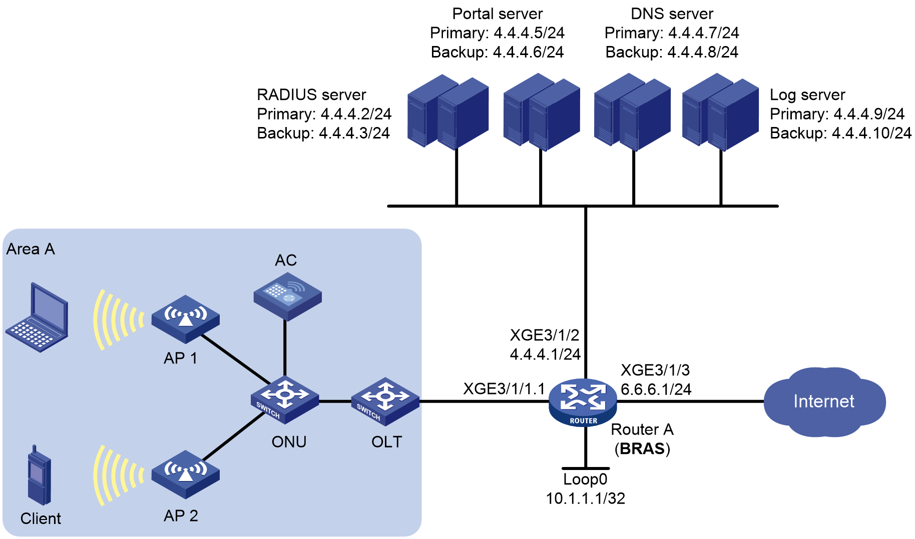
Analysis
· Configure the preauthentication domain to implement the following:
¡ After the wireless endpoint connects to the ISP's Wi-Fi, it obtains an IP address in the preauthentication domain (similar to the IPoE binding authentication process except for the configuration of direct IP address assignment without authentication in the domain).
¡ Enable the BRAS device to redirect wireless endpoint access to a specific URL to the Wi-Fi authentication page pushed by the ISP. After the user enters the account and password, the Portal server forwards the account and password to the BRAS device. The BRAS device then initiates authentication to the AAA server. After passing the authentication, the endpoint comes online in the Web authentication domain.
· Configure authorization address pool settings for the preauthentication domain. The Web authentication domain does not require authorization address pool configuration.
· Configure different user groups for the preauthentication domain and the Web authentication domain.
· For users in the preauthentication domain, configure QoS policy settings on the BRAS device to redirect the URLs accessed by the endpoints, and apply the redirection policy globally.
· (Optional.) In the wireless access scenario, you can verify SSIDs during user authentication through configuring the aaa ssid awifi command.
· In order to ensure that users can access the Web authentication page in the preauthentication domain stage, you can configure the URL whitelist feature through object group configuration, and add the portal server address and DNS server address to the URL whitelist.
· To facilitate QoS policy control, perform the following authorization operations on different user groups according to user status:
¡ Users in the preauthentication domain have not yet passed IPoE Web authentication. Assign such users to the user group named pre (preauthentication domain user group) to implement access control.
¡ Users in the post-authentication domain do not require access control. Assign such users to the user group named web_normal (Web user group).
· Implement QoS policy control for users in the preauthentication domain user group and Web user group as follows:
¡ For users in the preauthentication domain user group:
- Allow them to access the portal server and DNS server.
- Steer traffic accessing the portal server and DNS server to the CGN module for NAT address translation.
- Redirect HTTP/HTTPS access requests to the Web authentication page (http://4.4.4.5:8080/portal/ in this example), and discard all other traffic.
¡ For users in the Web user group:
- Allow them to access any destination address.
- Steer traffic accessing any destination address to the CGN module for NAT address translation.
Procedure
Configuring IP addresses and routes
# Assign IPv4 address 4.4.4.1/24 and IPv6 address 4::1/64 to Ten-GigabitEthernet 3/1/2 on the BRAS.
<BRAS> system-view
[BRAS] interface ten-gigabitethernet 3/1/2
[BRAS-Ten-GigabitEthernet3/1/2] ip address 4.4.4.1 24
[BRAS-Ten-GigabitEthernet3/1/2] ipv6 address 4::1 64
[BRAS-Ten-GigabitEthernet3/1/2] quit
# Assign IPv4 address 6.6.6.1/24 and IPv6 address 6::1/64 to Ten-GigabitEthernet 3/1/3 on the BRAS.
[BRAS] interface ten-gigabitethernet 3/1/3
[BRAS-Ten-GigabitEthernet3/1/3] ip address 6.6.6.1 24
[BRAS-Ten-GigabitEthernet3/1/3] ipv6 address 6::1 64
[BRAS-Ten-GigabitEthernet3/1/3] quit
# Configure default routes to the Internet.
[BRAS] ip route-static 0.0.0.0 0 6.1.1.2
[BRAS] ipv6 route-static :: 0 6::2
Configuring the DNS servers
In this example, Windows Server 2016 is used to describe the basic DNS server configuration. The configurations for the primary and secondary DNS servers are similar. This section uses the primary DNS server as an example. For information about configuring the log servers, see the corresponding software descriptions.
To configure a DNS server:
1. Install the DNS component:
a. Log in to the server, click Windows, and select Server Manager.
b. Click Add Roles and Features, and configure DNS.
c. On the Before you begin page, click Next.
d. On the Select installation type page, use the default option (Role-based or feature-based installation), and click Next.
e. On the Select destination server page, use the default option (Select a server from the server pool), and click Next.
f. On the Select server roles page, select DNS Server. On the Add Roles and Features Wizard page that opens, click Add Features, and then click Next.
g. On the Select features page, use the default settings, and click Next.
h. On the DNS Server page, click Next.
i. Click Install on the Confirm installation selections page and wait for the installation to complete.
j. Once installation completes, click Close to complete the installation of the DNS component.
2. Create an IPv4 forward lookup zone:
a. On the Server Manager page, click Tools, and select DNS.
b. Right-click Forward Lookup Zones on the DNS Manager page and select New Zone.
c. On the New Zone Wizard page, click Next.
d. On the Zone Type page, select Primary zone, and click Next.
e. On the Zone Name page, enter zone name ipv4.test.com.
f. On the Zone File page, use the default settings and click Next.
g. On the Dynamic Update page, select Do not allow dynamic updates and click Next.
h. On the New Zone Wizard page, click Finish.
i. On the DNS Manager page, click Forward Lookup Zones, right-click ipv4.test.com, and click New Host.
j. On the New Host page, enter host name www, enter IP address 4.4.4.7, and click Add Host.
The IPv4 forward lookup zone has been successfully created.
3. Create an IPv4 reverse lookup zone:
a. Right-click Reverse Lookup Zones on the DNS Manager page and select New Zone.
b. On the New Zone Wizard page, click Next.
c. On the Zone Type page, select Primary zone, and click Next.
d. On the Reverse Lookup Zone Name page, select IPv4 Reverse Lookup Zone, and click Next.
e. On the Reverse Lookup Zone Name page, enter network ID 4.4.4, and click Next.
f. On the Zone File page, use the default settings and click Next.
g. On the Dynamic Update page, select Do not allow dynamic updates and click Next.
h. On the New Zone Wizard page, click Finish.
i. On the DNS Manager page, click Reverse Lookup Zones, right-click 4.4.4.in-addr.arpa.dns, and click New Pointer.
j. On the New Resource Record page, enter host IP address 4.4.4.7, enter host name www.ipv4.test.com, and click OK.
The IPv4 reverse lookup zone has been successfully created.
4. Create an IPv6 forward lookup zone:
a. On the Server Manager page, click Tools, and select DNS.
b. Right-click Forward Lookup Zones on the DNS Manager page and select New Zone.
c. On the New Zone Wizard page, click Next.
d. On the Zone Type page, select Primary zone, and click Next.
e. On the Zone Name page, enter zone name ipv6.test.com.
f. On the Zone File page, use the default settings and click Next.
g. On the Dynamic Update page, select Do not allow dynamic updates and click Next.
h. On the New Zone Wizard page, click Finish.
i. On the DNS Manager page, click Forward Lookup Zones, right-click ipv6.test.com, and click New Host.
j. On the New Host page, enter host name www, enter IP address 4::7, and click Add Host.
The IPv6 forward lookup zone has been successfully created.
5. Create an IPv6 reverse lookup zone:
a. Right-click Reverse Lookup Zones on the DNS Manager page and select New Zone.
b. On the New Zone Wizard page, click Next.
c. On the Zone Type page, select Primary zone, and click Next.
d. On the Reverse Lookup Zone Name page, select IPv6 Reverse Lookup Zone, and click Next.
e. On the Reverse Lookup Zone Name page, enter network ID 4000:0000:0000:0000::/64, and click Next.
f. On the Zone File page, use the default settings and click Next.
g. On the Dynamic Update page, select Do not allow dynamic updates and click Next.
h. On the New Zone Wizard page, click Finish.
i. On the DNS Manager page, click Reverse Lookup Zones, right-click 0.0.0.0.0.0.0.0.0.0.0.0.0.0.0.4.in-addr.arpa.dns, and click New Pointer.
j. On the New Resource Record page, enter host IP address 4000.0000.0000.0000.0000.0000.0000.0007, enter host name www.ipv6.test.com, and click OK.
The IPv6 reverse lookup zone has been successfully created.
Configuring the BRAS device
1. Configure the DHCP server
# Enable DHCP globally.
<BRAS> system-view
[BRAS] dhcp enable
# Enable the DHCP server to return a DHCP-NAK message if the client notions of their IP addresses are incorrect.
[BRAS] dhcp server request-ip-address check
# Create a DHCP address pool named wlan_pool and enter its view.
[BRAS] ip pool wlan_pool bas local
# Specify 3.3.3.0/24 as the IP address range for dynamic allocation in the DHCP address pool.
[BRAS-ip-pool-wlan_pool] gateway 3.3.3.1 24
# Exclude IP address 3.3.3.1 from dynamic allocation in the DHCP address pool.
[BRAS-ip-pool-wlan_pool] forbidden-ip 3.3.3.1
# Specify DNS server addresses in the DHCP address pool.
[BRAS-ip-pool-wlan_pool] dns-list 4.4.4.7 4.4.4.8
[BRAS-ip-pool-wlan_pool] quit
2. Configure global NAT
a. Associate a failover group with the CGN modules
# Create failover group failgrp and enter its view.
[BRAS] failover group failgrp id 1
# Associate the failover group with CGN modules: Configure the node in slot 5 as the primary node in failover group failgrp and configure the node in slot 6 as the secondary node in the failover group.
[BRAS-failover-group-failgrp] bind slot 5 primary //If the module supports CPU, you must specify the CPU parameter after the slot.
[BRAS-failover-group-failgrp] bind slot 6 secondary
[BRAS-failover-group-failgrp] quit
b. Associate a service instance group with the failover group
# Create service instance group sgrp and enter its view.
[BRAS] service-instance-group sgrp
# Associate service instance group sgrp with failover group failgrp.
[BRAS-service-instance-group-sgrp] failover-group failgrp
[BRAS-service-instance-group-sgrp] quit
c. Configure an advanced ACL
# Create IPv4 advanced ACL 3000.
[BRAS] acl advanced 3000
# Create an IPv4 advanced ACL rule to translate the IP addresses of user packets of internal network 3.3.3.0/24.
[BRAS-acl-ipv4-adv-3000] rule permit ip source 3.3.3.0 0.0.0.255
[BRAS-acl-ipv4-adv-3000] quit
d. Configure global NAT
# Create a NAT address group numbered 1. Add public address range 6.6.6.2 to 6.6.6.255, specify the port range as 1024 to 65535, and set the port block size to 256 and the number of extended port blocks to 3 in NAT address group 1.
[BRAS] nat address-group 1
[BRAS-address-group-1] address 6.6.6.2 6.6.6.255
[BRAS-address-group-1] port-range 1024 65535
[BRAS-address-group-1] port-block block-size 256 extended-block-number 3 extended-block-size 1024
# Create NAT instance inst.
[BRAS] nat instance inst id 1
# Associate NAT instance inst with service instance group sgrp.
[BRAS-nat-instance-inst] service-instance-group sgrp
# Configure an outbound dynamic PAT rule to translate the IP addresses of outgoing packets of internal network 3.3.3.0/24.
[BRAS-nat-instance-inst] nat outbound 3000 address-group 1
[BRAS-nat-instance-inst] quit
e. Configure the triple mode (source address, source port number, protocol type)
# Apply the Endpoint-Independent Mapping mode to TCP and UDP packets for address translation.
[BRAS] nat mapping-behavior endpoint-independent tcp udp
f. Enable NAT ALG
|
|
NOTE: This section provides only ALG configuration for commonly-used FTP and PPTP protocols. To enable ALG for other protocols in your network, see the NAT configuration guide of the product and perform the configuration as needed. |
# Enable ALG for FTP and PPTP.
[BRAS] nat alg ftp (default configuration)
[BRAS] nat alg pptp
g. Configure NAT logging
|
|
NOTE: Log output can consume a certain amount of system resources. To avoid excessive logs consuming a large amount of system resources, this section provides the configuration for only basic NAT log in China CMCC format. If you need other types of log output in your network, see the NAT configuration guide of the product and perform the configuration as needed. |
# Enable NAT logging.
[BRAS] nat log enable
# Enable logging for port usage in port blocks and set the threshold to 90%.
[BRAS] nat log port-block port-usage threshold 90
# Enable NAT user logging for port block assignment.
[BRAS] nat log port-block-assign
# Enable NAT user logging for port block withdrawal.
[BRAS] nat log port-block-withdraw
# Enable fast log output in China CMCC format.
[BRAS] customlog format cmcc
# Configure the timestamp of fast output logs to show the system time.
[BRAS] customlog timestamp localtime
# Use the IP address of Loopback 0 as the source IP address of fast output logs.
[BRAS] interface loopback 0
[BRAS-LoopBack0] ip address 10.1.1.1 32
[BRAS-LoopBack0] quit
[BRAS] customlog host source loopback0
# Output NAT session logs and NAT444 user logs in China CMCC format to the log hosts at 4.4.4.9 and 4.4.4.10.
[BRAS] customlog host 4.4.4.9 port 1000 export cmcc-sessionlog cmcc-userlog sysname logserver01
[BRAS] customlog host 4.4.4.10 port 1000 export cmcc-sessionlog cmcc-userlog sysname logserver02
3. Configure portal authentication servers
# Create the first portal authentication server named newpt01, specify its IP address as 4.4.4.5, and specify the key as 123456.
[BRAS] portal server newpt01
[BRAS-portal-server-newpt01] ip 4.4.4.5 key simple 123456
[BRAS-portal-server-newpt01] quit
# Create the second portal authentication server named newpt02, specify its IP address as 4.4.4.6, and specify the key as 123456.
[BRAS] portal server newpt02
[BRAS-portal-server-newpt02] ip 4.4.4.6 key simple 123456
[BRAS-portal-server-newpt02] quit
4. Specify the HTTPS redirect listening port number
# Specify the HTTPS redirect listening port number. (To avoid port conflict, do not specify a TCP port number used by any other service. To display TCP port numbers that have been used by services, use the display tcp command.)
[BRAS] http-redirect https-port 11111
5. Configure the device to get user access information from ARP entries
[BRAS] portal access-info trust arp
6. Create local user groups
# Create a preauthentication domain user group named pre.
[BRAS] user-group pre
New user group added.
[BRAS-ugroup-pre] quit
# Create a post-authentication domain user group named web_normal for normal users.
[BRAS] user-group web_normal
New user group added.
[BRAS-ugroup-web_normal] quit
7. Configure a URL allowlist
# Create an IP address object group (URL allowlist) named freeurl_ipv4, and add the portal and DNS server addresses to the URL allowlist. (Because BRAS device communicates directly with the RADIUS server and log server and users are not involved, you do not need to add them to the allowlist.)
[BRAS] object-group ip address freeurl_ipv4
BRAS-obj-grp-ip-freeurl_ipv4] network host address 4.4.4.5 //Portal server address (primary)
[BRAS-obj-grp-ip-freeurl_ipv4] network host address 4.4.4.6 //Portal server address (backup)
[BRAS-obj-grp-ip-freeurl_ipv4] network host address 4.4.4.7 //DNS server address (primary)
[BRAS-obj-grp-ip-freeurl_ipv4] network host address 4.4.4.8 //DNS server address (backup)
[BRAS-obj-grp-ip-freeurl_ipv4] quit
8. Configure redirection policies
a. Configure ACL rules for preauthentication domain users.
# Create a rule for IPv4 advanced ACL web_permit to match packets accessing the IP addresses in the allowlist for the users in user group pre.
[BRAS] acl advanced name web_permit
[BRAS-acl-ipv4-adv-web_permit] rule 0 permit ip destination object-group freeurl_ipv4 user-group pre
[BRAS-acl-ipv4-adv-web_permit] quit
# Create a rule for IPv4 advanced ACL web_out to match packets sourced from the IP addresses in the allowlist for the users in user group pre.
[BRAS] acl advanced name web_out
[BRAS-acl-ipv4-adv-web_out] rule 0 permit ip source object-group freeurl_ipv4 user-group pre
[BRAS-acl-ipv4-adv-web_out] quit
# Create a rule for IPv4 advanced ACL web_http to match TCP packets (HTTP packets) with destination port 80 for the users in user group pre.
[BRAS] acl advanced name web_http
[BRAS-acl-ipv4-adv-web_http] rule 0 permit tcp destination-port eq www user-group pre
[BRAS-acl-ipv4-adv-web_http] quit
# Create a rule for IPv4 advanced ACL web_https to match TCP packets (HTTP packets) with destination port 443 for the users in user group pre.
[BRAS] acl advanced name web_https
[BRAS-acl-ipv4-adv-web_https] rule 0 permit tcp destination-port eq 443 user-group pre
[BRAS-acl-ipv4-adv-web_https] quit
# Create a rule for IPv4 advanced ACL ip to match all IP packets for the users in user group pre.
[BRAS] acl advanced name ip
[BRAS-acl-ipv4-adv-ip] rule 0 permit ip user-group pre
[BRAS-acl-ipv4-adv-ip] quit
# Create a rule for IPv4 advanced ACL web_normal to match all IP packets for the users in user group web_normal.
[BRAS] acl advanced name web_normal
[BRAS-acl-ipv4-adv-web_normal] rule 0 permit ip user-group web_normal
[BRAS-acl-ipv4-adv-web_normal] quit
b. Configure traffic classes used for user authentication
# Configure traffic class web_permit to match ACL web_permit.
[BRAS] traffic classifier web_permit operator or
[BRAS-classifier-web_permit] if-match acl name web_permit
[BRAS-classifier-web_permit] quit
# Configure traffic class web_out to match ACL web_out.
[BRAS] traffic classifier web_out operator or
[BRAS-classifier-web_out] if-match acl name web_out
[BRAS-classifier-web_out] quit
# Configure traffic class web_http to match ACL web_http.
[BRAS] traffic classifier web_http operator or
[BRAS-classifier-web_http] if-match acl name web_http
[BRAS-classifier-web_http] quit
# Configure traffic class web_https to match ACL web_https.
[BRAS] traffic classifier web_https operator or
[BRAS-classifier-web_https] if-match acl name web_https
[BRAS-classifier-web_https] quit
# Configure traffic class web_deny to match ACL ip.
[BRAS] traffic classifier web_deny operator or
[BRAS-classifier-web_deny] if-match acl name ip
[BRAS-classifier-web_deny] quit
# Configure traffic class web_normal to match ACL web_normal.
[BRAS] traffic classifier web_normal operator or
[BRAS-classifier-web_normal] if-match acl name web_normal
[BRAS-classifier-web_normal] quit
c. Configure traffic behaviors
# Configure traffic behavior web_permit, bind a NAT instance, and redirect the following packets to CGN modules for NAT processing:
- Packets whose destination address is the portal server address for users in user group pre.
- Packets whose destination address is the DNS server address for users in user group pre.
[BRAS] traffic behavior web_permit
[BRAS-behavior-web_permit] bind nat-instance inst
[BRAS-behavior-web_permit] free account
[BRAS-behavior-web_permit] quit
# Configure traffic behavior web_out to permit packets whose source address is the portal or DNS server address in user group pre to pass through.
[BRAS] traffic behavior web_out
[BRAS-behavior-web_out] filter permit
[BRAS-behavior-web_out] free account
[BRAS-behavior-web_out] quit
# Configure traffic behavior web_http to redirect TCP packets (HTTP packets) with destination port 80 for the users in user group pre to the CPU.
[BRAS] traffic behavior web_http
[BRAS-behavior-web_http] redirect http-to-cpu
[BRAS-behavior-web_http] quit
# Configure traffic behavior web_https to redirect TCP packets (HTTPS packets) with destination port 443 for the users in user group pre to the CPU.
[BRAS] traffic behavior web_https
[BRAS-behavior-web_https] redirect https-to-cpu
[BRAS-behavior-web_https] quit
# Configure traffic behavior web_deny to prohibit all IP packets in user group pre from passing through.
[BRAS] traffic behavior web_deny
[BRAS-behavior-web_deny] filter deny
[BRAS-behavior-web_deny] free account
[BRAS-behavior-web_deny] quit
# Configure traffic behavior web_normal, bind a NAT instance, and redirect all IP packets for users in user group web_normal to the CGN module for NAT processing.
[BRAS] traffic behavior web_normal
[BRAS-behavior-web_normal] bind nat-instance inst
[BRAS-behavior-web_normal] quit
d. Configure QoS policies
# Configure inbound QoS policy web.
[BRAS] qos policy web
# Associate traffic behaviors with traffic classes to meet the following requirements:
For users in user group pre:
- Redirect packets destined for the portal or DNS server to the CGN module for NAT processing.
- Redirect packets with destination port 80 (HTTP packets) or 443 (HTTPS packets) to the CPU.
- Prohibit any other packets from passing through.
For users in user group web_normal:
- Redirect all packets to the CGN module for NAT processing.
[BRAS-qospolicy-web] classifier web_permit behavior web_permit
[BRAS-qospolicy-web] classifier web_http behavior web_http
[BRAS-qospolicy-web] classifier web_https behavior web_https
[BRAS-qospolicy-web] classifier web_deny behavior web_deny
[BRAS-qospolicy-web] classifier web_normal behavior web_normal
[BRAS-qospolicy-web] quit
# Configure outbound QoS policy out.
[BRAS] qos policy out
# Associate traffic behaviors with traffic classes to meet the following requirements:
- For users in user group pre: Permit packets with the portal or DNS server address as the source address to pass through, and prohibit any other packets from passing through.
- For users in user group web_normal: Permit all packets to pass through. (No class-behavior association is required. Traffic that does not match any ACL rules will be forwarded according to routing table lookup.)
[BRAS-qospolicy-out] classifier web_out behavior web_out
[BRAS-qospolicy-out] classifier web_deny behavior web_deny
[BRAS-qospolicy-out] quit
e. Configure application policies
# Apply QoS policy web to received user traffic. (After applying the policy, you can execute the display qos policy global inbound command to examine whether the policy has taken effect.)
[BRAS] qos apply policy web global inbound
# Apply QoS policy out to sent online user traffic. (After applying the policy, you can execute the display qos policy global outbound command to examine whether the policy has taken effect.)
[BRAS] qos apply policy out global outbound
9. Configure a RADIUS scheme
# Create a RADIUS scheme named rs1 and enter its view.
[BRAS] radius scheme rs1
# Configure the primary and backup authentication servers and accounting servers, and the keys for the servers to communicate.
[BRAS-radius-rs1] primary authentication 4.4.4.2
[BRAS-radius-rs1] primary accounting 4.4.4.2
[BRAS-radius-rs1] secondary authentication 4.4.4.3
[BRAS-radius-rs1] secondary accounting 4.4.4.3
[BRAS-radius-rs1] key authentication simple 123456
[BRAS-radius-rs1] key accounting simple 123456
# Configure the device to interpret the RADIUS class attribute as CAR parameters.
[BRAS-radius-rs1] attribute 25 car
# Enable the RADIUS attribute translation feature.
[BRAS-radius-rs1] attribute translate
# Specify the IP address of interface Loopback 0 (10.1.1.1) as the source IP address for outgoing RADIUS packets.
[BRAS-radius-rs1] nas-ip 10.1.1.1
# Exclude the ISP domain names from the usernames sent to the RADIUS servers.
[BRAS-radius-rs1] user-name-format without-domain
[BRAS-radius-rs1] quit
# Enable the RADIUS DAS feature. Specify the DACs as 4.4.4.2 and 4.4.4.3. Set the shared key to 123456 in plaintext form for secure communication between the DAS and DACs.
[BRAS] radius dynamic-author server
[BRAS-radius-da-server] client ip 4.4.4.2 key simple 123456
[BRAS-radius-da-server] client ip 4.4.4.3 key simple 123456
[BRAS-radius-da-server] quit
10. Configure Track (typically for the primary Web authentication page URL)
a. Configure an NQA operation (with administrator admin and operation tag test1)
# Create an NQA operation with administrator name admin and operation tag test1.
[BRAS] nqa entry admin test1
# Specify HTTP as the NQA operation type.
[BRAS-nqa-admin-test1] type http
# Configure the URL that the HTTP operation visits as http://4.4.4.5:8080/portal/.
[BRAS-nqa-admin-test1-http] url http://4.4.4.5:8080/portal/
# Set the operation type to get for the HTTP operation. (This configuration is optional, because the default operation type is get.)
[BRAS-nqa-admin-test1-http] operation get
# Configure the operation to repeat every 100 milliseconds.
[BRAS-nqa-admin-test1-http] frequency 100
# Configure reaction entry 1, specifying that five consecutive probe failures trigger the Track module.
[BRAS-nqa-admin-test1-http] reaction 1 checked-element probe-fail threshold-type consecutive 5 action-type trigger-only //Note that the last keyword is trigger-only, rather than trap-only.
# Enable the saving of history records for the NQA operation, and set the maximum number of history records to 10 for the operation.
[BRAS-nqa-admin-test1-http] history-record enable
[BRAS-nqa-admin-test1-http] history-record number 10
[BRAS-nqa-admin-test1-http] quit
# Perform the operation until you stop it.
[BRAS] nqa schedule admin test1 start-time now lifetime forever
b. Configure a track entry
# Configure track entry 1, and associate it with reaction entry 1 of the NQA operation (with administrator admin and operation tag test1).
[BRAS] track 1 nqa entry admin test1 reaction 1
[BRAS-track-1] quit
11. Configure the preauthentication domain and Web authentication domain
# Configure preauthentication domain pre_wlan for IPoE users, and specify IPv4 address pool wlan_pool as the authorization address pool.
[BRAS] domain name pre_wlan
[BRAS-isp-pre_wlan] authentication ipoe none
[BRAS-isp-pre_wlan] authorization ipoe none
[BRAS-isp-pre_wlan] accounting ipoe none
[BRAS-isp-pre_wlan] authorization-attribute ip-pool wlan_pool
# Configure the primary and backup Web authentication page URLs, and the primary and backup Web authentication server IP addresses.
[BRAS-isp-pre_wlan] web-server url http://4.4.4.5:8080/portal/
[BRAS-isp-pre_wlan] web-server url http://4.4.4.6:8080/portal secondary
[BRAS-isp-pre_wlan] web-server ip 4.4.4.5
[BRAS-isp-pre_wlan] web-server ip 4.4.4.6 secondary
# Specify the private IPv4 address type for users in preauthentication domain pre_wlan. NAT address allocation is triggered upon successful authentication of the users of the private IPv4 address type.
[BRAS-isp-pre_wlan] user-address-type private-ipv4
# Add the user IP address to the Web server URL.
[BRAS-isp-pre_wlan] web-server url-parameter userip source-address
# Bind preauthentication domain user group pre to NAT instance inst.
[BRAS-isp-pre_wlan] user-group name pre bind nat-instance inst
[BRAS-isp-pre_wlan] quit
# Configure authentication domain wlan for IPoE users during Web authentication.
[BRAS] domain name wlan
[BRAS-isp-wlan] authentication ipoe radius-scheme rs1
[BRAS-isp-wlan] authorization ipoe radius-scheme rs1
[BRAS-isp-wlan] accounting ipoe radius-scheme rs1
# Specify the private IPv4 address type for users in post-authentication domain wlan. NAT address allocation is triggered upon successful authentication of the users of the private IPv4 address type.
[BRAS-isp-wlan] user-address-type private-ipv4
# Bind post-authentication domain user group web_normal to NAT instance inst.
|
|
NOTE: The NAT instance bound to the post-authentication domain user group must be the same as that bound to the preauthentication domain user group. |
[BRAS-isp-wlan] user-group name web_normal bind nat-instance inst
# Configure the device to allow users that encounter accounting-start failures to stay online. (Default configuration.)
[BRAS-isp-wlan] accounting start-fail online
[BRAS-isp-wlan] quit
12. Configure IPoE
# Enter the view of subinterface Ten-GigabitEthernet 3/1/1.1.
[BRAS] interface ten-gigabitethernet 3/1/1.1
# Enable user VLAN QinQ termination on Ten-GigabitEthernet 3/1/1.1. Configure the interface to terminate VLAN-tagged packets with Layer 1 VLAN ID 20 and Layer 2 VLAN ID 10.
[BRAS-Ten-GigabitEthernet3/1/1.1] user-vlan dot1q vid 20 second-dot1q 10
# Enable Ten-GigabitEthernet 3/1/1.1 to transmit broadcast and multicast packets.
|
|
NOTE: This configuration applies to only ambiguous QinQ termination. It is used to identify QinQ termination support and is not required. |
[BRAS-Ten-GigabitEthernet3/1/1.1] vlan-termination broadcast enable
# Enable local proxy ARP and proxy ARP on Ten-GigabitEthernet 3/1/1.1. (Proxy ARP is required for inter-user access.)
[BRAS-Ten-GigabitEthernet3/1/1.1] local-proxy-arp enable
[BRAS-Ten-GigabitEthernet3/1/1.1] proxy-arp enable
[BRAS-Ten-GigabitEthernet3/1/1.1] quit
# Enable IPoE and configure the Layer 2 access mode for users on Ten-GigabitEthernet 3/1/1.1.
[BRAS–Ten-GigabitEthernet3/1/1.1] ip subscriber l2-connected enable
# Enable unclassified-IPv4 packet initiation on Ten-GigabitEthernet 3/1/1.1.
[BRAS–Ten-GigabitEthernet3/1/1.1] ip subscriber initiator unclassified-ip enable matching-user
# Enable ARP packet initiation.
[BRAS–Ten-GigabitEthernet3/1/1.1] ip subscriber initiator arp enable
# Configure the Web authentication method for IPoE users.
[BRAS–Ten-GigabitEthernet3/1/1.1] ip subscriber authentication-method web
The operation may cut all users on this interface. Continue?[Y/N] :y
# Specify ISP domain pre_wlan as the preauthentication domain and ISP domain wlan for Web authentication.
[BRAS–Ten-GigabitEthernet3/1/1.1] ip subscriber pre-auth domain pre_wlan
[BRAS–Ten-GigabitEthernet3/1/1.1] ip subscriber web-auth domain wlan
# Configure online detection for IPv4 protocol stack users on Ten-GigabitEthernet 3/1/1.1. The maximum number of detection attempts is 3 after the first failure, the detection timer is 60 seconds, and the detection packet type is ARP.
[BRAS–Ten-GigabitEthernet3/1/1.1] ip subscriber user-detect ip arp retry 3 interval 60
# Enable roaming for IPoE individual users.
[BRAS–Ten-GigabitEthernet3/1/1.1] ip subscriber roaming enable
# Specify the NAS-Port-Type attribute as 802.11.
[BRAS–Ten-GigabitEthernet3/1/1.1] nas-port-type 802.11
# (Optional.) Set the SSID on the interface.
[BRAS–Ten-GigabitEthernet3/1/1.1] aaa ssid awifi
[BRAS–Ten-GigabitEthernet3/1/1.1] quit
Configuring the RADIUS server (primary RADIUS server in this example)
|
|
NOTE: This section takes Srun 4.1.0 server as an example to illustrate basic RADIUS server configuration. The configuration might vary by Srun software version. For more information, see the Srun server manual of the associated version. This section is for illustration only. |
1. Add access device and RADIUS attribute.
a. Open the browser and type http://4.4.4.2:8081 to enter the login page.
b. Enter the administrator account, password, and verification code, and then click Login to log in to the accounting management system.
c. Click Devices > Add Device and configure the following required parameters:
- Device name—NAS device name (BRAS in this example).
- NAS IP—NAS IP address (IP address of interface Loopback 0 on BRAS in this example).
- IP—IP address of the host where the Srun software is installed (4.4.4.2 in this example).
- NAS type—Options are Huawei, H3C, and Srun gateway.
- RADIUS key—Key used for communication between the NAS and RADIUS (123456 in this example).
d. Specify relevant information for the added device based on the content described in step 3.
e. Click Save to save your settings.
f. (Optional) Add the RADIUS attribute
# From the navigation bar, click RADIUS > Add RADIUS Attributes to add the associated attribute.
g. Set up RADIUS trust
# From the navigation bar, click RADIUS > Radius Trust Setting to enter the RADIUS trust settings page. Click Generate in the upper right corner repeatedly until the trusted device table is generated successfully.
h. Restart the RADIUS service
After the trusted device table is generated, you need to restart the radiusd service to validate the modification.
Log in to the Srun server command line interface, as shown in Figure 53. First execute the killall radiusd command to shut down the radiusd service, and then execute the /srun3/radius/sbin/radiusd & command to restart the radiusd service.
Figure 55 Restarting the RADIUS service
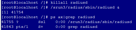
2. Configure the policy and user
a. Open the browser and type https://4.4.4.2:8080 to enter the Srun software login page.
b. Enter the administrator account, password, and verification code, and then click Login.
c. From the left navigation bar, click Account > Add. On the page that opens, enter username user1 and password pass1 of Host A.
d. Use default settings for other parameters, and then click Save to save the user configuration.
Configuring the portal server (primary Web server in this example)
|
|
NOTE: This example uses iMC of the PLAT 7.3 (E0705P02) version as an example to illustrate basic portal server configuration. The configuration might vary by iMC version. For more information, see the iMC server manual of the associated version. This section is for illustration only. |
1. Configure the portal home page.
Select User Access Policy > Portal Service > Server from the navigation tree to enter the server configuration page. Configure the portal home page by using the default settings, and then click OK.
2. Configure an IP address group for portal authentication
Select User Access Policy > Portal Service > IP Group from the navigation tree to enter the IP address group configuration page. Click Add to add an IPv4 address group.
¡ Enter IP address group name IPoE_Web_User.
¡ Enter start IP address 3.3.3.1 and end IP address 3.3.3.255. Specify that the user IP address must be included in the IP address group range.
¡ Select the NAT type. Enter start IP address 6.6.6.2 and end IP address 6.6.6.255 (consistent with the NAT address group configured for the BRAS device).
¡ Use the default settings for other parameters.
¡ Click OK.
3. Add the portal access device information
Select User Access Policy > Portal Service > Device from the navigation tree to enter the device configuration page. Click Add to configure the device information.
¡ Enter device name NAS.
¡ Enter IP address 10.1.1.1 (IP address of interface Loopback 0 on the BRAS device).
¡ Enter key 123456.
¡ Select Directly Connect for access method.
¡ Use default settings for other parameters, and then click OK.
4. Configure port group information
Select User Access Policy > Portal Service > Device from the navigation tree, and click Port Group Info Management to enter the port group information configuration page.
Click Add.
¡ Enter port group name group.
¡ Select the NAT option, and then select IP address group IPoE_Web_User. The IP address used upon network access of the user must belong to the selected IP address group.
¡ Use default settings for other parameters, and then click OK.
Verifying the configuration
# After the user passes preauthentication, display IPoE session information to verify that the user has obtained IP address 3.3.3.2.
[BRAS] display access-user auth-type pre-auth
UserID Interface IP address MAC address S-/C-VLAN
Username Access type
IPv6 address
0x33d XGE3/1/1.1 3.3.3.2 0015-e947-f4d4 20/10
0015e947f4d4 L2 IPoE dynamic(D/-)
-
# After the user passes preauthentication, enter the username and password on the Web log page, and then click Log In to perform Web authentication. You can use the following command display IPoE session information.
[BRAS] display access-user auth-type web-auth
UserID Interface IP address MAC address S-/C-VLAN
Username Access type
IPv6 address
0x33d XGE3/1/1.1 3.3.3.2 0015-e947-f4d4 20/10
user1 Web auth
-
You can execute the display nat port-block dynamic command to view dynamic port block mappings generated by the device for online users.
Configuration files
#
failover group failgrp id 1
bind slot 5 primary
bind slot 6 secondary
#
dhcp enable
dhcp server request-ip-address check
#
object-group ip address freeurl_ipv4
0 network host address 4.4.4.5
10 network host address 4.4.4.6
20 network host address 4.4.4.7
30 network host address 4.4.4.8
#
traffic classifier web_deny operator or
if-match acl name ip
#
traffic classifier web_http operator or
if-match acl name web_http
#
traffic classifier web_https operator or
if-match acl name web_https
#
traffic classifier web_normal operator or
if-match acl name web_normal
#
traffic classifier web_out operator or
if-match acl name web_out
#
traffic classifier web_permit operator or
if-match acl name web_permit
#
traffic behavior web_deny
filter deny
free account
#
traffic behavior web_http
redirect http-to-cpu
#
traffic behavior web_https
redirect https-to-cpu
#
traffic behavior web_normal
bind nat-instance inst
#
traffic behavior web_out
filter permit
free account
#
traffic behavior web_permit
free account
bind nat-instance inst
#
qos policy out
classifier web_out behavior web_out
classifier web_deny behavior web_deny
#
qos policy web
classifier web_permit behavior web_permit
classifier web_http behavior web_http
classifier web_https behavior web_https
classifier web_deny behavior web_deny
classifier web_normal behavior web_normal
#
ip pool wlan_pool bas local
gateway 3.3.3.1 mask 255.255.255.0
dns-list 4.4.4.7 4.4.4.8
forbidden-ip 3.3.3.1
#
interface LoopBack0
ip address 10.1.1.1 255.255.255.255
#
interface Ten-GigabitEthernet3/1/1.1
local-proxy-arp enable
proxy-arp enable
ip subscriber initiator arp enable
user-vlan dot1q vid 20 second-dot1q 10
vlan-termination broadcast enable
ip subscriber l2-connected enable
ip subscriber user-detect ip arp retry 3 interval 60
ip subscriber authentication-method web
ip subscriber roaming enable
nas-port-type 802.11
ip subscriber pre-auth domain pre_wlan
ip subscriber web-auth domain wlan
ip subscriber initiator unclassified-ip enable matching-user
aaa ssid awifi
#
interface Ten-GigabitEthernet3/1/2
ip address 4.4.4.1 255.255.255.0
ipv6 address 4::1 64
#
interface Ten-GigabitEthernet3/1/3
ip address 6.6.6.1 255.255.255.0
ipv6 address 6::1 64
#
customlog format cmcc
customlog host 4.4.4.9 port 1000 export cmcc-sessionlog cmcc-userlog sysname logserver01
customlog host 4.4.4.10 port 1000 export cmcc-sessionlog cmcc-userlog sysname logserver02
customlog host source LoopBack0
customlog timestamp localtime
#
ip route-static 0.0.0.0 0 6.1.1.1
ipv6 route-static :: 0 6::1
#
qos apply policy web global inbound
qos apply policy out global outbound
#
nqa entry admin test1
type http
frequency 100
history-record enable
history-record number 10
reaction 1 checked-element probe-fail threshold-type consecutive 5 action-type trigger-only
url http://4.4.4.5:8080/portal/
#
nqa schedule admin test1 start-time now lifetime forever
#
acl advanced 3000
rule 5 permit ip source 3.3.3.0 0.0.0.255
#
acl advanced name ip
rule 0 permit ip user-group pre
#
acl advanced name web_http
rule 0 permit tcp destination-port eq www user-group pre
#
acl advanced name web_https
rule 0 permit tcp destination-port eq 443 user-group pre
#
acl advanced name web_normal
rule 0 permit ip user-group web_normal
#
acl advanced name web_out
rule 0 permit ip source object-group freeurl_ipv4 user-group pre
#
acl advanced name web_permit
rule 0 permit ip destination object-group freeurl_ipv4 user-group pre
#
radius scheme rs1
primary authentication 4.4.4.2
primary accounting 4.4.4.2
secondary authentication 4.4.4.3
secondary accounting 4.4.4.3
key authentication cipher $c$3$ys2rBH4AnFEsfD9ePu059altgP35LdThnQ==
key accounting cipher $c$3$cEuypR0HRcarmNum5IcwXP3A5Cw9QwZ2lQ==
user-name-format without-domain
nas-ip 10.1.1.1
attribute 25 car
attribute translate
#
radius dynamic-author server
client ip 4.4.4.2 key cipher $c$3$eypkQU6+h6OmpkzYwh1EXVjADY3hZxH1Zg==
client ip 4.4.4.3 key cipher $c$3$LUrPmr7bsRS0xbLPuuct/FzHatVHKROzcQ==
#
domain name pre_wlan
authorization-attribute ip-pool wlan_pool
authentication ipoe none
authorization ipoe none
accounting ipoe none
user-address-type private-ipv4
web-server url http://4.4.4.5:8080/portal/
web-server url http://4.4.4.6:8080/portal secondary
web-server ip 4.4.4.5
web-server ip 4.4.4.6 secondary
web-server url-parameter userip source-address
user-group name pre bind nat-instance inst
#
domain name wlan
authentication ipoe radius-scheme rs1
authorization ipoe radius-scheme rs1
accounting ipoe radius-scheme rs1
user-address-type private-ipv4
user-group name web_normal bind nat-instance inst
#
user-group pre
#
user-group web_normal
#
service-instance-group sgrp
failover-group failgrp
#
nat alg pptp
nat mapping-behavior endpoint-independent tcp udp
nat log enable
nat log port-block port-usage threshold 90
nat log port-block-assign
nat log port-block-withdraw
#
nat address-group 1
port-range 1024 65535
port-block block-size 256 extended-block-number 3 extended-block-size 1024
address 6.6.6.2 6.6.6.255
#
nat instance inst id 1
service-instance-group sgrp
nat outbound 3000 address-group 1
#
portal access-info trust arp
#
portal server newpt01
ip 4.4.4.5 key cipher $c$3$Fi3mkp3UlCe6/8SgNoFTadHsXmx84vuPuA==
#
portal server newpt02
ip 4.4.4.6 key cipher $c$3$XdXPD8OH+5xVZnViXy+IZOWOPe4alXYI8g==
#
http-redirect https-port 11111
#
Government and enterprise VPN configuration example (dual stack+PD)
Government and enterprise VPN services are divided into common VPN and L2VPN. In the common VPN service, the BRAS device can be configured with IPoE static leased line, interface-leased line, and subnet-leased line. In an L2VPN network, an IPoE L2VPN user represents all users accessing the interface. For VPN users, authentication and billing are not required.
Network configuration
As shown in Figure 56, Router A serves as the operator's BRAS device, providing access services for government and enterprise customers. The device is a Layer 3 device for a customer. VPN users come online through IPoE static leased line by using unknown source IP packets, ARP packets, and NS/NA packets.
· Static VPN users access the BRAS in IPoE mode through a Layer 2 network.
¡ For the IPv4 protocol stack, access can be triggered by unknown source IPv4 packets and ARP packets.
¡ For the IPv6 protocol stack, access can be triggered by unknown source IPv6 packets and NS/NA packets.
· VPN users are not authenticated or billed, and rate limit policies are issued to access interfaces.
· Port 80/8080 is blocked on the BRAS device (can be activated if necessary).
· Host users are dual-stack users.
¡ For the IPv4 protocol stack: The device serves as a DHCP server to assign users private addresses within the 192.168.1.0/24 network segment.
¡ For the IPv6 protocol stack: The same IPv6 address prefix is used, and IPv6 addresses are obtained through stateless automatic configuration. The IPv6 address prefix comes from the prefix 192::/64 of the IPv6 global unicast address 192::1/64 configured on the Ten-GigabitEthernet 3/1/1 of the device.
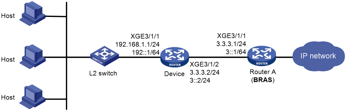
Analysis
· Configure a global static session on the BRAS device, and use static users as static leased users.
· To use IP packets to initiate IPoE static sessions, enable unclassified-IPv4 packet initiation.
· To use ARP packets to initiate IPv4 static sessions, enable ARP packet initiation and unclassified-IPv4 packet initiation. If the ARP packets match a configured IPoE static session, authentication is initiated.
· To use NS or NA packets to initiate IPv6 static sessions, enable NS/ NA packet initiation. If the NS or NA packets match a configured IPoE static session, authentication is initiated.
· To use ARP packets to initiate IPv4 static sessions, make sure the gateway address assigned to a static user is the IP address of the access interface or an IP address configured by using the gateway-list export-route command.
· For the BRAS device, Ten-GigabitEthernet 3/1/2 of the device is a static user.
¡ For IPv4: Because the BRAS device does not need to be aware of the specific users in the 192.168.1.0/24 network segment, there is only one IPv4 user, namely the IPv4 address 3.3.3.2 on Ten-GigabitEthernet 3/1/2 of the device. Therefore, the nat outbound command needs to be executed on the interface to perform NAT before user packets from the 192.168.1.0/24 network segment are sent to the BRAS device. The source IP address of the packets will be converted to the IPv4 address 3.3.3.2 on Ten-GigabitEthernet 3/1/2.
¡ Because the same IPv6 address prefix (192::/64) is used when users obtain IPv6 addresses through stateless automatic configuration, configure a PD prefix when configuring static sessions on the BRAS device. When a PD prefix is configured in the IPoE global static session, as long as the source IP address in the user's IPv6 packet can match any IPv6 address or PD prefix specified in the static session, the user can trigger the authentication process. Additionally, users on the same PD prefix network segment are considered as one user (the static user with the IPv6 address corresponding to the PD prefix) during the authentication process.
Procedure
Configuring IP addresses and routes
# Assign IPv4 address 3.3.3.2/24 to Ten-GigabitEthernet 3/1/2 on the BRAS.
<BRAS> system-view
[BRAS] interface ten-gigabitethernet 3/1/2
[BRAS-Ten-GigabitEthernet3/1/2] ip address 3.3.3.2 24
[BRAS-Ten-GigabitEthernet3/1/2] quit
# Configure static routes to the Internet.
[BRAS] ip route-static 192.168.1.0 24 3.3.3.2
[BRAS] ipv6 route-static 192:: 64 3::2
Configure the device
# Enable DHCP.
[Device] dhcp enable
# Configure IP address pool pool1 to allocate private network IPv4 addresses to internal network users.
[Device] ip pool pool1
[Device-ip-pool-pool1] network 192.168.1.0 24
[Device-ip-pool-pool1] gateway-list 192.168.1.1
[Device-ip-pool-pool1] dns-list 8.8.8.8
# Exclude IP address 192.168.1.1 from dynamic allocation.
[Device-ip-pool-pool1] forbidden-ip 192.168.1.1
[Device-ip-pool-pool1] quit
# Assign the IPv4 gateway address of internal network users to Ten-GigabitEthernet 3/1/1.
[Device] interface ten-gigabitethernet 3/1/1
[Device-Ten-GigabitEthernet3/1/1] ip address 192.168.1.1 24
# Configure an IPv6 global unicast address and disable RA message suppression on the interface.
[Device-Ten-GigabitEthernet3/1/1] ipv6 address 192::1/64
[Device-Ten-GigabitEthernet3/1/1] undo ipv6 nd ra halt
[Device-Ten-GigabitEthernet3/1/1] quit
# Enter the view of interface Ten-GigabitEthernet 3/1/2.
[Device] interface ten-gigabitethernet 3/1/2
# Configure an IPv4 address for the interface.
[Device-Ten-GigabitEthernet3/1/2] ip address 3.3.3.2 24
# (For IPv4.) Directly use the IP address of Ten-GigabitEthernet 3/1/2 to perform NAT for IP traffic from the internal network to the external network.
[Device-Ten-GigabitEthernet3/1/2] nat outbound
# Configure an IPv6 global multicast address for the interface.
[Device-Ten-GigabitEthernet3/1/2] ipv6 address 3::2/64
# Configure the default route.
[Device] ip route-static 0.0.0.0 0 3.3.3.1
[Device] ipv6 route-static :: 0 3::1
Configure the BRAS device
1. Configure the authentication domain:
# Create ISP domain dm1, and enter its view.
[BRAS] domain name dm1
# Configure AAA methods in ISP domain dm1.
[BRAS-isp-dm1] authentication ipoe none
[BRAS-isp-dm1] authorization ipoe none
[BRAS-isp-dm1] accounting ipoe none
[BRAS-isp-dm1] quit
2. Configure CAR:
# Enter the view of interface Ten-GigabitEthernet 3/1/1.
[BRAS] interface ten-gigabitethernet 3/1/1
# Configure CAR in the inbound and outbound directions to limit all packets to 112600 kbps.
[BRAS-Ten-GigabitEthernet3/1/1] qos car inbound any cir 112600
[BRAS-Ten-GigabitEthernet3/1/1] qos car outbound any cir 112600
[BRAS–Ten-GigabitEthernet3/1/1] quit
3. Deny the Web service:
¡ Configure an ACL:
# Create an IP advanced ACL named web_deny, and configure rules to match packets with destination port 80 and destination port 8080.
[BRAS] acl advanced name web_deny
[BRAS-acl-ipv4-adv-web_deny] rule 10 permit tcp destination-port eq www
[BRAS-acl-ipv4-adv-web_deny] rule 20 permit tcp destination-port eq 8080
[BRAS-acl-ipv4-adv-web_deny] quit
¡ Configure traffic classes for users in the preauthentication domain:
# Create a traffic class named web_deny, and use ACL web_deny as the match criterion.
[BRAS] traffic classifier web_deny operator or
[BRAS-classifier-web_deny] if-match acl name web_deny
[BRAS-classifier-web_deny] quit
¡ Configure a traffic behavior:
Configure traffic behavior web_deny.
[BRAS] traffic behavior web_deny
[BRAS-behavior-web_deny] filter deny
[BRAS-behavior-web_deny] free account
[BRAS-behavior-web_deny] quit
¡ Configure a QoS policy:
# Configure a QoS policy named web_deny for inbound traffic.
[BRAS] qos policy web_deny
[BRAS-qospolicy-web_deny] classifier web_deny behavior web_deny
[BRAS-qospolicy-web_deny] quit
¡ Apply the QoS policy:
# Enter the view of interface Ten-GigabitEthernet 3/1/1.
[BRAS] interface ten-gigabitethernet 3/1/1
# Apply the QoS policy to the inbound direction of the interface.
[BRAS-Ten-GigabitEthernet3/1/1] qos apply policy web_deny inbound
[BRAS–Ten-GigabitEthernet3/1/1] quit
4. Configure a user gateway:
# Enable DHCP globally.
[BRAS] dhcp enable
# Create an IPv4 address pool named pool1. Specify network segment 3.3.3.0/24 for dynamic allocation, specify gateway 3.3.3.1 for the pool, and exclude IPv4 addresses 3.3.3.1 and 3.3.3.2, which is used by the static user.
[BRAS] ip pool pool1
[BRAS-ip-pool-pool1] network 3.3.3.0 24 export-route
[BRAS-ip-pool-pool1] gateway-list 3.3.3.1 export-route //When the device actively sends online requests to users, the device preferentially uses the address as the source IPv4 address of online requests.
[BRAS-ip-pool-pool1] forbidden-ip-range 3.3.3.1 3.3.3.2
[BRAS-ip-pool-pool1] quit
# Create an IPv6 address pool named pool1. Specify a gateway for the address pool. Exclude IPv6 addresses 3::1 and 3::2 (which must be the same as the user addresses specified in the IPoE static sessions) from the address pool for dynamic allocation.
[BRAS] ipv6 pool pool1
[BRAS-ipv6-pool-pool1] network 3::/64 export-route
[BRAS-ipv6-pool-pool1] forbidden-address 3::1 3::2
[BRAS-ipv6-pool-pool1] quit
# Enter the view of interface Ten-GigabitEthernet 3/1/1.
[BRAS] interface ten-gigabitethernet 3/1/1
# Configure an IPv6 global multicast address for the interface, and disable RA message suppression.
When the device actively sends online requests to users, the device preferentially uses the address as the source IPv6 address of online requests.
[BRAS-Ten-GigabitEthernet3/1/1] ipv6 address 3::1/64
[BRAS-Ten-GigabitEthernet3/1/1] undo ipv6 nd ra halt
5. Configure IPoE:
# Enable local proxy ARP and common proxy ARP. With proxy ARP, hosts in different broadcast domains can communicate with each other as they do on the same network.
[BRAS-Ten-GigabitEthernet3/1/1] local-proxy-arp enable
[BRAS-Ten-GigabitEthernet3/1/1] proxy-arp enable
# Enable IPoE and configure Layer 2 access mode.
[BRAS–Ten-GigabitEthernet3/1/1] ip subscriber l2-connected enable
# Enable unclassified-IPv4 packet initiation.
[BRAS–Ten-GigabitEthernet3/1/1] ip subscriber initiator unclassified-ip enable matching-user
# Enable ARP packet initiation.
[BRAS–Ten-GigabitEthernet3/1/1] ip subscriber initiator arp enable
# Enable unclassified-IPv6 packet initiation.
[BRAS–Ten-GigabitEthernet3/1/1] ip subscriber initiator unclassified-ipv6 enable matching-user
# Enable NS/NA packet initiation.
[BRAS–Ten-GigabitEthernet3/1/1] ip subscriber initiator nsna enable
# Configure online detection for IPv4 and IPv6 protocol stack users. The maximum number of detection attempts is 3 after the first failure, the detection timer is 60 seconds, and the detection packet type is ARP.
[BRAS–Ten-GigabitEthernet3/1/1] ip subscriber user-detect ip arp retry 3 interval 60
[BRAS–Ten-GigabitEthernet3/1/1] ip subscriber user-detect ipv6 nd retry 3 interval 60
[BRAS–Ten-GigabitEthernet3/1/1] quit
# Configure a global IPoE static session with an IPv4 address of 1.1.1.1, an IPv6 address of 3::2, a PD prefix of 192::/64, and an ISP domain of dm1.
[BRAS] ip subscriber session static ip 3.3.3.2 ipv6 3::2 delegation-prefix 192:: 64 domain dm1 interface ten-gigabitethernet 3/1/1 request-online gateway ip 3.3.3.1 ipv6 3::1
Verifying the configuration
# After an IPoE user passes authentication, execute the following command to view the online information of the IPoE user.
[BRAS] display access-user interface ten-gigabitethernet 3/1/1
UserID Interface IP address MAC address S-/C-VLAN
Username Access type
IPv6 address
0x5c XGE3/1/1 3.3.3.2 147b-1924-0206 -/-
3.3.3.2 L2 IPoE dynamic(D/D)
3::2
Configuration files
· Device:
#
dhcp enable
#
ip pool pool1
network 192.168.1.0 24
gateway-list 192.168.1.1
dns-list 8.8.8.8
forbidden-ip 192.168.1.1
#
interface ten-gigabitethernet 3/1/1
ip address 192.168.1.1 24
ipv6 address 192::1/64
undo ipv6 nd ra halt
#
interface ten-gigabitethernet 3/1/2
ip address 3.3.3.2 24
nat outbound
ipv6 address 3::2/64
#
ip route-static 0.0.0.0 0 3.3.3.1
ipv6 route-static :: 0 3::1
#
· BRAS:
#
dhcp enable
#
traffic classifier web_deny operator or
if-match acl name web_deny
#
traffic behavior web_deny
filter deny
free account
#
qos policy web_deny
classifier web_deny behavior web_deny
#
ip pool pool1
gateway-list 3.3.3.1 export-route
network 3.3.3.0 mask 255.255.255.0 export-route
forbidden-ip-range 3.3.3.1 3.3.3.2
#
ipv6 pool pool1
network 3::/64 export-route
forbidden-address 3::1 3::2
#
ip subscriber session static ip 3.3.3.2 ipv6 3::2 delegation-prefix 192:: 64 domain dm1 interface ten-gigabitethernet 3/1/1 request-online gateway ip 3.3.3.1 ipv6 3::1
#
domain name dm1
authentication ipoe none
authorization ipoe none
accounting ipoe none
#
interface ten-gigabitethernet 3/1/1
proxy-arp enable
local-proxy-arp enable
ip subscriber initiator arp enable
qos car inbound any cir 112600 cbs 7037500 ebs 0
qos car outbound any cir 112600 cbs 7037500 ebs 0
qos apply policy web_deny inbound
ip address 3.3.3.1 24
ipv6 address 3::1/64
undo ipv6 nd ra halt
ip subscriber initiator nsna enable
ip subscriber l2-connected enable
ip subscriber user-detect ip arp retry 3 interval 60
ip subscriber user-detect ipv6 nd retry 3 interval 60
ip subscriber initiator unclassified-ip enable matching-user
ip subscriber initiator unclassified-ipv6 enable matching-user
#
interface ten-gigabitethernet 3/1/2
ip address 3.3.3.2 24
#
ip route-static 192.168.1.0 24 3.3.3.2
ipv6 route-static 192:: 64 3::2
#
acl advanced name web_deny
rule 10 permit tcp destination-port eq www
rule 20 permit tcp destination-port eq 8080
#
ITMS and VoIP service configuration example (dual stack)
Integrated Terminal Management System (ITMS) is used for device registration, automatic configuration initialization, remote troubleshooting and repair, and device monitoring for home gateways. Voice over Internet Protocol (VoIP) carries home landline services such as IP-based voice and fax.
ITMS/VoIP services use binding authentication methods, and are accessed through IPoE DHCP, typically without authentication and billing.
Network configuration
As shown in Figure 57, Router A serves as the operator's BRAS device, providing access services for ITMS/VoIP by using IPoE DHCP. The specific network requirements are as follows:
· A host accesses the BRAS in IPoE mode through a Layer 2 network.
· The BRAS device acts as a DHCP server to assign IP addresses to terminals.

Analysis
· The configuration methods for ITMS and VoIP are basically the same. This document describes only the configuration example for ITMS.
· ITMS and VoIP use MPLS VPN forwarding in the MAN, so VPN instances need to be assigned to different services.
· To use ITMS/VoIP services, set the local authorized address pool and VPN. For VoIP, the service type needs to be set as VoIP.
Procedure
Configure MPLS L3VPN
# Configure a VPN instance named ITMS.
<BRAS> system-view
[BRAS] ip vpn-instance itms
[BRAS-vpn-instance-ITMS] quit
Configure the DHCP server
# Enable DHCP globally.
[BRAS] dhcp enable
# Enable the DHCP server to return a DHCP-NAK message if the client notions of their IP addresses are incorrect.
[BRAS] dhcp server request-ip-address check
# Create address pool pool1 and enter its view.
[BRAS] ip pool pool1 bas local
# Specify primary subnet 3.3.3.0/24 for dynamic allocation in the address pool. Specify gateway address 3.3.3.1 and DNS server address 8.8.8.8 in the address pool.
[BRAS-ip-pool-pool1] gateway 3.3.3.1 24
[BRAS-ip-pool-pool1] dns-list 8.8.8.8
# Exclude IP address 3.3.3.1 from dynamic allocation.
[BRAS-ip-pool-pool1] forbidden-ip 3.3.3.1
# Apply the IP pool to VPN instance ITMS.
[BRAS-ip-pool-pool1] vpn-instance ITMS
[BRAS-ip-pool-pool1] quit
# Create IPv6 address pool pool1 and enter its view.
[BRAS-server] ipv6 pool pool1
# Specify primary subnet 3::/64 for dynamic allocation in the address pool, and specify DNS server address 8::8 in the address pool.
[BRAS-server-ipv6-pool-pool1] network 3::/64
[BRAS-server-ipv6-pool-pool1] dns-server 8::8
# Exclude IPv6 address 3::1 from dynamic allocation.
[BRAS-server-ipv6-pool-pool1] forbidden-address 3::1
# Apply the IPv6 pool to VPN instance ITMS.
[BRAS-server-ipv6-pool-pool1] vpn-instance ITMS
[BRAS-server-ipv6-pool-pool1] quit
# Enable the DHCPv6 server on GigabitEthernet 3/1/1.1.
[BRAS-server] interface gigabitethernet 3/1/1.1
[BRAS-server-GigabitEthernet3/1/1.1] ipv6 dhcp select server
# Automatically generate a link-local address. The IPv6 link-local address is to be used as the gateway of users.
[BRAS-server-GigabitEthernet3/1/1.1] ipv6 address auto link-local
# Enable the interface to advertise RA messages. Set the M flag bit to 1. When the M flag is set to 1 in RA advertisements, hosts obtain IPv6 addresses from an DHCPv6 server. Set the other stateful configuration flag (O) to 1 in RA advertisements to be sent. When the O flag is set to 1 in RA advertisements, hosts obtain configuration information other than IPv6 addresses from an DHCPv6 server.
[BRAS-server-GigabitEthernet3/1/1.1] undo ipv6 nd ra halt
[BRAS-server-GigabitEthernet3/1/1.1] ipv6 nd autoconfig managed-address-flag
[BRAS-server-GigabitEthernet3/1/1.1] ipv6 nd autoconfig other-flag
[BRAS-server-GigabitEthernet3/1/1.1] quit
Configure the authentication domain
# Create ISP domain dm1, and enter its view.
[BRAS] domain name dm1
# Perform no authentication for IPoE users in the ISP domain, authorize IP pools, and authorize a VPN instance.
[BRAS-isp-dm1] authentication ipoe none
[BRAS-isp-dm1] authorization ipoe none
[BRAS-isp-dm1] accounting ipoe none
[BRAS-isp-dm1] authorization-attribute ip-pool pool1
[BRAS-isp-dm1] authorization-attribute ipv6-pool pool1
[BRAS-isp-dm1] authorization-attribute vpn-instance ITMS
# Authorize a user priority. The device uses the specified user priority to perform QoS priority mapping on user packets, and then assigns the user packets to a queue based on the target priority. Packets in a high-priority queue are preferentially scheduled when congestion occurs. In addition, the device replaces the value of the IP Precedence field in upstream packets of users with the specified user priority.
[BRAS-isp-dm1] authorization-attribute user-priority inbound 5
[BRAS-isp-dm1] quit
Configure IPoE
# Enter the view of subinterface GigabitEthernet 3/1/1.1.
[BRAS] interface ten-gigabitethernet 3/1/1.1
# Configure the subinterface to terminate VLAN-tagged packets with Layer 1 VLAN ID as 20 and Layer 2 VLAN ID as 10.
[BRAS-Ten-GigabitEthernet3/1/1.1] user-vlan dot1q vid 20 second-dot1q 10
# Enable the subinterface to transmit broadcasts and multicasts.
[BRAS-Ten-GigabitEthernet3/1/1.1] vlan-termination broadcast enable
|
|
NOTE: This command is required only for ambiguous Dot1q termination. This example uses unambiguous Dot1q termination and does not require this command. |
# Enable local proxy ARP and common proxy ARP. This step is required for authorization VPN scenarios.
[BRAS-Ten-GigabitEthernet3/1/1.1] local-proxy-arp enable
[BRAS-Ten-GigabitEthernet3/1/1.1] proxy-arp enable
# Enable IPoE and configure Layer 2 access mode.
[BRAS–Ten-GigabitEthernet3/1/1.1] ip subscriber l2-connected enable
# Enable unclassified-IP packet initiation.
[BRAS–Ten-GigabitEthernet3/1/1.1] ip subscriber initiator unclassified-ip enable matching-user
# Enable ARP packet initiation.
[BRAS–Ten-GigabitEthernet3/1/1.1] ip subscriber initiator arp enable
# Enable unclassified-IPv6 packet initiation.
[BRAS–Ten-GigabitEthernet3/1/1.1] ip subscriber initiator unclassified-ipv6 enable matching-user
# Enable NS/NA packet initiation.
[BRAS–Ten-GigabitEthernet3/1/1.1] ip subscriber initiator nsna enable
# Specify dm1 as the ISP domain for DHCP users.
[BRAS–Ten-GigabitEthernet3/1/1.1] ip subscriber dhcp domain dm1
[BRAS–Ten-GigabitEthernet3/1/1.1] quit
Verifying the configuration
# Execute the following command to view the online information of the IPoE user.
[BRAS] display access-user interface ten-gigabitethernet 3/1/1.1
UserID Interface IP address MAC address S-/C-VLAN
Username Access type
IPv6 address
0x5c XGE3/1/1.1 3.3.3.2 000c-29a6-b656 20/10
000c29a6b656 L2 IPoE dynamic(D/D)
3::2
Configuration files
#
dhcp enable
dhcp server request-ip-address check
#
ip pool pool1 bas local
vpn-instance ITMS
gateway 3.3.3.1 mask 255.255.255.0
dns-list 8.8.8.8
forbidden-ip 3.3.3.1
#
ipv6 pool pool1
vpn-instance ITMS
network 3::/64
dns-server 8::8
forbidden-address 3::1
#
interface ten-gigabitethernet 3/1/1.1
proxy-arp enable
local-proxy-arp enable
ip subscriber initiator arp enable
user-vlan dot1q vid 20 second-dot1q 10
vlan-termination broadcast enable
ipv6 dhcp select server
ipv6 address auto link-local
ipv6 nd autoconfig managed-address-flag
ipv6 nd autoconfig other-flag
undo ipv6 nd ra halt
ip subscriber initiator nsna enable
ip subscriber l2-connected enable
ip subscriber dhcp domain dm1
ip subscriber initiator unclassified-ip enable matching-user
ip subscriber initiator unclassified-ipv6 enable matching-user
#
domain name dm1
authorization-attribute ip-pool pool1
authorization-attribute ipv6-pool pool1
authorization-attribute vpn-instance ITMS
authorization-attribute user-priority inbound 5
authentication ppp local
authorization ppp local
accounting ppp local
authentication ipoe none
authorization ipoe none
accounting ipoe none
#
IPTV service configuration example
Internet Protocol Television (IPTV) services are divided into two categories: video on demand (VoD) and live broadcasting. VoD services use unicast traffic, while live broadcasting services use multicast traffic. The set-top box (STB), which is the IPTV access terminal, can access the network through PPPoE or IPoE.
Network configuration
As shown in Figure 58, Router A is the BRAS device of the operator, Switch A is the ONU device, and Switch B is the OLT device, providing access services for IPTV users to watch live broadcasting and VoD. Users can use the STB to choose VoD or watch live broadcasting services on their home network TV.
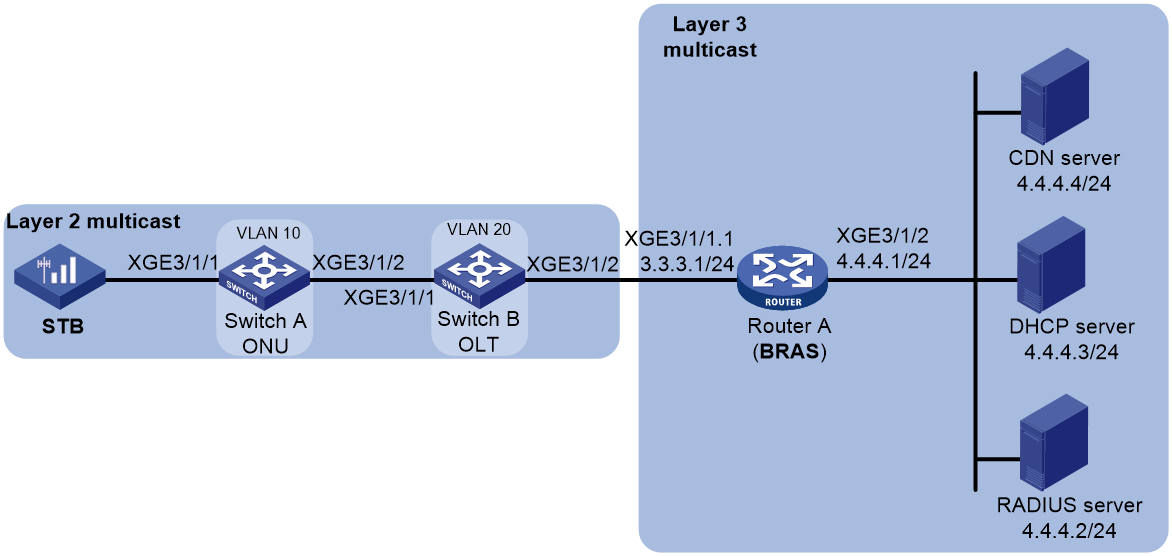
Analysis
Both IPoE and PPPoE share the following configurations:
· When using DHCP relay networking, specify the DHCP server under the relay address pool to obtain IP addresses and other network parameters.
· When a user clicks to watch a specific live TV program, the STB sends an IGMP report message to the multicast replication device (the replication device can be an OLT, aggregation switch, or BRAS device. In this example, Switch B (OLT) is the multicast replication device). The device judges whether the user can join the multicast group according to the user's multicast access policy.
· IPTV services require network access authentication and business access authentication. Network access authentication is completed by the BRAS device and RADIUS server, and business access authentication is completed by the CDN (Content Delivery Network) server system.
· When configuring multicast, configure PIM-SM on the upstream port (Ten-GigabitEthernet 3/1/2) of the BRAS device and IGMP on the downstream port (Ten-GigabitEthernet3/1/1.1); configure IGMP snooping and multicast VLAN on both the OLT and ONU.
For IPoE users, IPoE network access authentication is divided into session-level authentication and non-session level authentication.
· Session-level authentication requires the BRAS device to extract the terminal's account password, and the authentication is completed through interaction between the BRAS device and the AAA server. The DHCP server is only responsible for allocating addresses.
· Non-session-level authentication does not require the BRAS device to authenticate the account password of the terminal. The authentication is completed through interaction between the DHCP server and AAA server. After receiving the DHCP protocol message from the user, the BRAS device transparently transmits it to the DHCP server, and the DHCP server and AAA server interact to complete the authentication and allocate the address to the terminal. This example uses non-session level authentication.
For PPPoE users:
· IPTV services using PPPoE authentication are similar to broadband services, and the STB initiates authentication.
· The IPTV service traffic can only be terminated by the BRAS device.
Procedure (IPoE)
Configure IP multicast
# Enable IP multicast routing on the BRAS device.
<BRAS> system-view
[BRAS] multicast routing
[BRAS-mrib] quit
# Assign IPv4 address 3.3.3.1/24 to Ten-GigabitEthernet 3/1/1.1 on the BRAS device, and enable IGMP, multicast access control, and enable per-session multicast forwarding for BRAS users on the interface.
[BRAS] interface ten-gigabitethernet 3/1/1.1
[BRAS-Ten-GigabitEthernet3/1/1.1] ip address 3.3.3.1 24
[BRAS-Ten-GigabitEthernet3/1/1.1] igmp enable
[BRAS-Ten-GigabitEthernet3/1/1.1] igmp authorization-enable
[BRAS-Ten-GigabitEthernet3/1/1.1] igmp join-by-session mode bras
[BRAS-Ten-GigabitEthernet3/1/1.1] quit
# Assign IPv4 address 4.4.4.1/24 to Ten-GigabitEthernet 3/1/2 on the BRAS device, and enable PIM-SM on the interface.
[BRAS] interface ten-gigabitethernet 3/1/2
[BRAS-Ten-GigabitEthernet3/1/2] ip address 4.4.4.1 24
[BRAS-Ten-GigabitEthernet3/1/2] pim sm
[BRAS-Ten-GigabitEthernet3/1/2] quit
# Create loopback interface LoopBack100 on the BRAS device, assign IPv4 address 1.1.1.1/32 to the interface, and enable PIM-SM on the interface.
[BRAS] interface loopback 100
[BRAS-LoopBack100] ip address 1.1.1.1 32
[BRAS-LoopBack100] pim sm
[BRAS-LoopBack100] quit
# Configure the BRAS device as a C-BSR and C-RP.
[BRAS] pim
[BRAS-pim] c-bsr 1.1.1.1
[BRAS-pim] c-rp 1.1.1.1
[BRAS-pim] quit
# Enable IGMP snooping globally on Switch A.
<SwitchA> system-view
[SwitchA] igmp-snooping
[SwitchA-mrib] quit
# Create VLAN 10 on Switch A, add Ten-GigabitEthernet 3/1/1 and Ten-GigabitEthernet 3/1/2 to the VLAN, and enable IGMP snooping for the VLAN.
[SwitchA-vlan 10] port ten-gigabitethernet 3/1/1 to ten-gigabitethernet 3/1/2
[SwitchA-vlan 10] igmp-snooping enable
[SwitchA-vlan 10] quit
# Enable IGMP snooping globally on Switch B.
<SwitchB> system-view
[SwitchB] igmp-snooping
[SwitchB-mrib] quit
# Create VLAN 20 on Switch B, add Ten-GigabitEthernet 3/1/1 and Ten-GigabitEthernet 3/1/2 to the VLAN, and enable IGMP snooping for the VLAN.
[SwitchB] vlan 20
[SwitchB-vlan 20] port ten-gigabitethernet 3/1/1 to ten-gigabitethernet 3/1/2
[SwitchB-vlan 20] igmp-snooping enable
[SwitchB-vlan 20] quit
Configure the DHCP server
# Enable DHCP globally.
<DHCP-server> system-view
[DHCP-server] dhcp enable
# Enable the DHCP server to return a DHCP-NAK message if the client notions of their IP addresses are incorrect.
[DHCP-server] dhcp server request-ip-address check
# Create address pool iptvpool and enter its view.
[DHCP-server] ip pool iptvpool
# Specify primary subnet 3.3.3.0/24 for dynamic allocation in the address pool.
[DHCP-server-ip-pool-iptvpool] network 3.3.3.0 24
# Specify gateway address 3.3.3.1.
[DHCP-server-ip-pool-iptvpool] gateway-list 3.3.3.1
# Exclude IP address 3.3.3.1 from dynamic allocation.
[DHCP-server-ip-pool-iptvpool] forbidden-ip 3.3.3.1
[DHCP-server-ip-pool-iptvpool] quit
# Configure a static route to forward packets destined to 3.3.3.0/24 to next hop 4.4.4.1. Then, DHCP replies destined to network 3.3.3.0/24 will be forwarded to 4.4.4.1, the IP address of the interface connecting to the DHCP client network.
[DHCP-server] ip route-static 3.3.3.0 24 4.4.4.1
Configure the BRAS device
1. Configure DHCP relay:
# Enable DHCP.
[BRAS] dhcp enable
# Create DHCP relay address pool iptvpool, and specify gateway addresses and the DHCP server for the address pool.
[BRAS] ip pool iptvpool bas remote
[BRAS-ip-pool-iptvpool] gateway 3.3.3.1 24
[BRAS-ip-pool-iptvpool] forbidden-ip 3.3.3.1
[BRAS-ip-pool-iptvpool] remote-server 4.4.4.3
2. Configure a user group:
# Create local user group itv.
[BRAS] user-group itv
[BRAS-ugroup-itv] quit
3. Configure an ISP domain:
# Create ISP domain dm1, and enter its view.
[BRAS] domain name dm1
# Perform no authentication for IPoE users in ISP domain dm1.
[BRAS-isp-dm1] authentication ipoe none
[BRAS-isp-dm1] authorization ipoe none
[BRAS-isp-dm1] accounting ipoe none
# Configure IP address pool iptvpool as the authorization IP pool.
[BRAS-isp-dm1] authorization-attribute ip-pool iptvpool
# Configure local user group itv as the authorization user group.
[BRAS-isp-dm1] authorization-attribute user-group itv
# Configure a user priority. The device uses the specified user priority to perform QoS priority mapping on user packets, and then assigns the user packets to a queue based on the target priority. Packets in a high-priority queue are preferentially scheduled when congestion occurs. In addition, the device replaces the value of the IP Precedence field in upstream packets of users with the specified user priority.
[BRAS-isp-dm1] authorization-attribute user-priority inbound 5
[BRAS-isp-dm1] quit
4. Configure IPoE:
# Enter the view of subinterface Ten-GigabitEthernet 3/1/1.1.
[BRAS] interface ten-gigabitethernet 3/1/1.1
# Configure the subinterface to terminate VLAN-tagged packets with Layer 1 VLAN ID as 20 and Layer 2 VLAN ID as 10.
[BRAS-Ten-GigabitEthernet3/1/1.1] user-vlan dot1q vid 20 second-dot1q 10
# Enable the subinterface to transmit broadcasts and multicasts.
[BRAS-Ten-GigabitEthernet3/1/1.1] vlan-termination broadcast enable
|
|
NOTE: This command is required only for ambiguous Dot1q termination. This example uses unambiguous Dot1q termination and does not require this command. |
# Enable local proxy ARP and common proxy ARP. With proxy ARP, hosts in different broadcast domains can communicate with each other as they do on the same network.
[BRAS-Ten-GigabitEthernet3/1/1.1] local-proxy-arp enable
[BRAS-Ten-GigabitEthernet3/1/1.1] proxy-arp enable
# Enable IPoE and configure the Layer 2 access mode.
[BRAS–Ten-GigabitEthernet3/1/1.1] ip subscriber l2-connected enable
# Enable unclassified-IPv4 packet initiation, and enable ARP packet initiation.
[BRAS–Ten-GigabitEthernet3/1/1.1] ip subscriber initiator unclassified-ip enable matching-user
[BRAS–Ten-GigabitEthernet3/1/1.1] ip subscriber initiator arp enable
# Specify dm1 as the ISP domain for DHCP users.
[BRAS–Ten-GigabitEthernet3/1/1.1] ip subscriber dhcp domain dm1
# Enable the DHCP relay agent to support Option 82.
[BRAS–Ten-GigabitEthernet3/1/1.1] dhcp relay information enable
[BRAS–Ten-GigabitEthernet3/1/1.1] quit
Procedure (PPPoE)
Configure IP multicast
# Enable IP multicast routing on the BRAS device.
<BRAS> system-view
[BRAS] multicast routing
[BRAS-mrib] quit
# Assign IPv4 address 3.3.3.1/24 to Ten-GigabitEthernet 3/1/1.1 on the BRAS device, and enable IGMP, multicast access control, and enable per-session multicast forwarding for BRAS users on the interface.
[BRAS] interface ten-gigabitethernet 3/1/1.1
[BRAS-Ten-GigabitEthernet3/1/1.1] ip address 3.3.3.1 24
[BRAS-Ten-GigabitEthernet3/1/1.1] igmp enable
[BRAS-Ten-GigabitEthernet3/1/1.1] igmp authorization-enable
[BRAS-Ten-GigabitEthernet3/1/1.1] igmp join-by-session mode bras
[BRAS-Ten-GigabitEthernet3/1/1.1] quit
# Assign IPv4 address 4.4.4.1/24 to Ten-GigabitEthernet 3/1/2 on the BRAS device, and enable PIM-SM on the interface.
[BRAS] interface ten-gigabitethernet 3/1/2
[BRAS-Ten-GigabitEthernet3/1/2] ip address 4.4.4.1 24
[BRAS-Ten-GigabitEthernet3/1/2] pim sm
[BRAS-Ten-GigabitEthernet3/1/2] quit
# Create loopback interface LoopBack100 on the BRAS device, assign IPv4 address 1.1.1.1/32 to the interface, and enable PIM-SM on the interface.
[BRAS] interface loopback 100
[BRAS-LoopBack100] ip address 1.1.1.1 32
[BRAS-LoopBack100] pim sm
[BRAS-LoopBack100] quit
# Configure the BRAS device as a C-BSR and C-RP.
[BRAS] pim
[BRAS-pim] c-bsr 1.1.1.1
[BRAS-pim] c-rp 1.1.1.1
[BRAS-pim] quit
# Enable IGMP snooping globally on Switch A.
<SwitchA> system-view
[SwitchA] igmp-snooping
[SwitchA-mrib] quit
# Create VLAN 10 on Switch A, add Ten-GigabitEthernet 3/1/1 and Ten-GigabitEthernet 3/1/2 to the VLAN, and enable IGMP snooping for the VLAN.
[SwitchA] vlan 10
[SwitchA-vlan 10] port ten-gigabitethernet 3/1/1 to ten-gigabitethernet 3/1/2
[SwitchA-vlan 10] igmp-snooping enable
[SwitchA-vlan 10] quit
# Enable IGMP snooping globally on Switch B.
<SwitchB> system-view
[SwitchB] igmp-snooping
[SwitchB-mrib] quit
# Create VLAN 20 on Switch B, add Ten-GigabitEthernet 3/1/1 and Ten-GigabitEthernet 3/1/2 to the VLAN, and enable IGMP snooping for the VLAN.
[SwitchB] vlan 20
[SwitchB-vlan 20] port ten-gigabitethernet 3/1/1 to ten-gigabitethernet 3/1/2
[SwitchB-vlan 20] igmp-snooping enable
[SwitchB-vlan 20] quit
Configure the DHCP server
# Enable DHCP globally.
<DHCP-server> system-view
[DHCP-server] dhcp enable
# Create address pool iptvpool and enter its view.
[DHCP-server] ip pool iptvpool
# Specify primary subnet 3.3.3.0/24 for dynamic allocation in the address pool.
[DHCP-server-ip-pool-iptvpool] network 3.3.3.0 24
# Specify gateway address 3.3.3.1.
[DHCP-server-ip-pool-iptvpool] gateway-list 3.3.3.1
# Exclude IP address 3.3.3.1 from dynamic allocation.
[DHCP-server-ip-pool-iptvpool] forbidden-ip 3.3.3.1
[DHCP-server-ip-pool-iptvpool] quit
# Configure a static route to forward packets destined to 3.3.3.0 to next hop 4.4.4.1. Then, DHCP replies destined to network 3.3.3.0 will be forwarded to 4.4.4.1, the IP address of the interface connecting to the DHCP client network.
[DHCP-server] ip route-static 3.3.3.0 24 4.4.4.1
Configure the BRAS device
1. Configure the DHCP relay:
# Enable DHCP.
[BRAS] dhcp enable
# Create DHCP relay address pool iptvpool, and specify gateway addresses and the DHCP server for the address pool.
[BRAS] ip pool iptvpool bas remote
[BRAS-ip-pool-iptvpool] gateway 3.3.3.1 24
[BRAS-ip-pool-iptvpool] forbidden-ip 3.3.3.1
[BRAS-ip-pool-iptvpool] remote-server 4.4.4.3
2. Configure a RADIUS scheme:
# Create RADIUS scheme rs1, and enter its view.
<BRAS> system-view
[BRAS] radius scheme rs1
# Configure primary servers and keys for authentication and accounting.
[BRAS-radius-rs1] primary authentication 4.4.4.2
[BRAS-radius-rs1] primary accounting 4.4.4.2
[BRAS-radius-rs1] key authentication simple 123456
[BRAS-radius-rs1] key accounting simple 123456
[BRAS-radius-rs1] quit
3. Configure a user group:
Create local user group itv.
[BRAS] user-group itv
[BRAS-ugroup-itv] quit
4. Configuring an ISP domain:
# Create ISP domain dm1, and enter its view.
[BRAS] domain name dm1
# Configure users to use RADIUS scheme rs1 for authentication, authorization, and accounting in the ISP domain.
[BRAS-isp-dm1] authentication ppp radius-scheme rs1
[BRAS-isp-dm1] authorization ppp radius-scheme rs1
[BRAS-isp-dm1] accounting ppp radius-scheme rs1
# Configure IP address pool iptvpool as the authorization IP pool.
[BRAS-isp-dm1] authorization-attribute ip-pool iptvpool
# Configure local user group itv as the authorization user group.
[BRAS-isp-dm1] authorization-attribute user-group itv
# Configure a user priority. The device uses the specified user priority to perform QoS priority mapping on user packets, and then assigns the user packets to a queue based on the target priority. Packets in a high-priority queue are preferentially scheduled when congestion occurs. In addition, the device replaces the value of the IP Precedence field in upstream packets of users with the specified user priority.
[BRAS-isp-dm1] authorization-attribute user-priority inbound 5
[BRAS-isp-dm1] quit
5. Configure PPPoE:
# Enter the view of subinterface Ten-GigabitEthernet 3/1/1.1.
[BRAS] interface ten-gigabitethernet 3/1/1.1
# Configure the subinterface to terminate VLAN-tagged packets with Layer 1 VLAN ID as 20 and Layer 2 VLAN ID as 10.
[BRAS-Ten-GigabitEthernet3/1/1.1] user-vlan dot1q vid 20 second-dot1q 10
# Enable the subinterface to transmit broadcasts and multicasts.
[BRAS-Ten-GigabitEthernet3/1/1.1] vlan-termination broadcast enable
|
|
NOTE: This command is required only for ambiguous Dot1q termination. This example uses unambiguous Dot1q termination and does not require this command. |
# (Optional) Enable local proxy ARP and common proxy ARP on the subinterface.
[BRAS-Ten-GigabitEthernet3/1/1.1] local-proxy-arp enable
[BRAS-Ten-GigabitEthernet3/1/1.1] proxy-arp enable
[BRAS-Ten-GigabitEthernet3/1/1.1] quit
# Configure Virtual-Template 1 to use PAP and CHAP for authenticating the peer.
[BRAS] interface virtual-template 1
[BRAS-Virtual-Template1] ppp authentication-mode pap chap domain default enable dm1
[BRAS-Virtual-Template1] quit
# Enable the PPPoE server on Ten-GigabitEthernet 3/1/1.1, and bind it to Virtual-Template 1.
[BRAS] interface ten-gigabitethernet 3/1/1.1
[BRAS-Ten-GigabitEthernet3/1/1.1] pppoe-server bind virtual-template 1
[BRAS-Ten-GigabitEthernet3/1/1.1] quit
Configure the RADIUS server
|
|
NOTE: This section uses the Srun software of version 4.1.0 as an example to describe how to configure basic settings of the RADIUS server. The configuration might be different for Srun software of different versions. For more information, see the Srun software manual. |
1. Add access devices.
a. Open your browser, enter http://4.4.4.2:8081 in the address bar, and press Enter to access the login page.
Figure 59 Login page
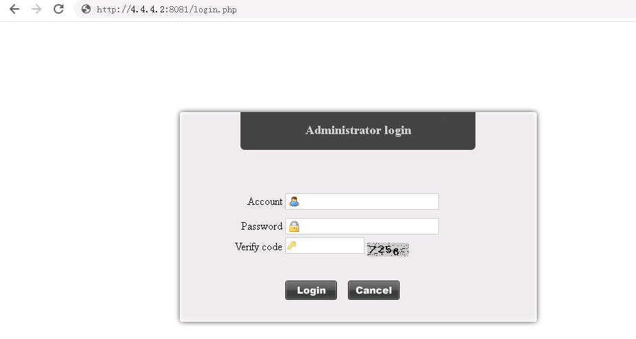
b. Enter the account, password, and verification code, and then click Login to log in to the billing management system.
Figure 60 Homepage
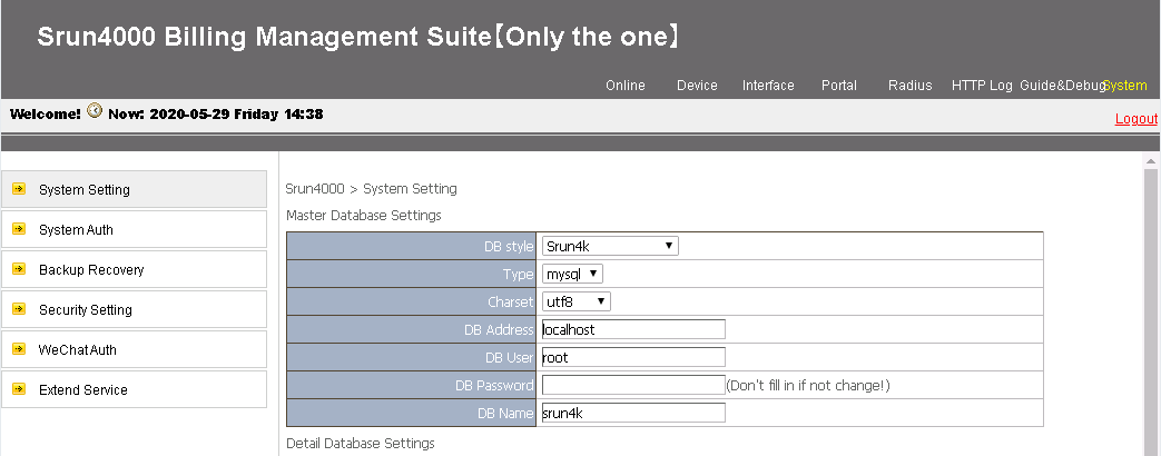
c. Select Device > Add Device. The following are required parameters:
- Device Name—Enter the device name of the NAS (the device name is BRAS in this example).
- NAS IP—Enter the IP address of the NAS (4.4.4.1, the IP address on the BRAS device in this example).
- IP—Enter the IP address of the host where the Srun software is installed (4.4.4.2 in this example).
- NAS type—Select Huawei, H3C, and Srun Gateways from the NAS type list.
- RADIUS key—Enter the key used for communication between the NAS and the RADIUS server (123456 in this example).
d. Click Save.
Figure 61 Adding a device
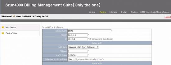
2. (Optional.) Add RADIUS attributes.
Click Radius > Add RADIUS Attributes to add RADIUS attributes.
3. Set the RADIUS trust.
Select RADIUS from the navigation tree. Click the RADIUS Trust Settings link to enter the RADIUS trust settings page. Click Generate in the upper right corner until the trust is successfully generated.
4. Re-enable the RADIUS service.
Re-enable the radiusd service to make the trust settings take effect.
To re-enable the RADIUS service, access the CLI of the Srun server, execute the killall radiusd command to disable the RADIUS service and then execute the /srun3/radius/sbin/radiusd & command to enable the RADIUS service.
Figure 62 Re-enabling the RADIUS service

5. Configure and policies and users
a. Open your browser, enter http://4.4.4.2:8080 in the address bar, and press Enter to access the login page.
b. Enter the account, password, and verification code, and then click Login to log in.
c. On the left navigation tree, select Account > Add User. Enter the account name and password for Host A. In this example, account name user1 and password pass1 are used.
d. Use default settings for other fields, and click Save.
Verifying the configuration
# After a PPPoE user passes authentication, use the display access-user command to view PPP user information.
[BRAS] display access-user interface ten-gigabitethernet 3/1/1.1
UserID Interface IP address MAC address S-/C-VLAN
Username Access type
IPv6 address
0xc XGE3/1/1.1 3.3.3.2 00e0-0001-0001 20/10
user1 PPPoE
-
# After a user passes authentication, use the following command to view online IPoE user information. The output shows that the user obtains IP address 3.3. 3.2.
[BRAS] display access-user interface ten-gigabitethernet 3/1/1.1
UserID Interface IP address MAC address S-/C-VLAN
Username Access type
IPv6 address
0x5 XGE3/1/1.1 3.3.3.2 00e0-0001-0001 20/10
00e000010001 L2 IPoE dynamic(D/-)
-
Configuration files (IPoE)
· DHCP server:
#
dhcp enable
dhcp server request-ip-address check
#
ip pool iptvpool
gateway-list 3.3.3.1
network 3.3.3.0 mask 255.255.255.0
forbidden-ip 3.3.3.1
#
interface ten-gigabitethernet3/1/2
ip address 4.4.4.3 255.255.255.0
#
ip route-static 3.3.3.0 24 4.4.4.1
#
· BRAS:
#
ip pool iptvpool bas remote
gateway 3.3.3.1 mask 255.255.255.0
forbidden-ip 3.3.3.1
remote-server 4.4.4.3
#
dhcp enable
#
multicast routing
#
interface LoopBack 100
ip address 1.1.1.1 255.255.255.255
pim sm
#
pim
c-bsr 1.1.1.1
c-rp 1.1.1.1
#
domain name dm1
service-type stb
authentication ipoe none
authorization ipoe none
accounting ipoe none
authorization-attribute ip-pool iptvpool
authorization-attribute user-group itv
authorization-attribute user-priority inbound 5
#
interface ten-gigabitethernet 3/1/1.1
ip address 3.3.3.1 255.255.255.0
igmp enable
igmp authorization-enable
igmp join-by-session mode bras
user-vlan dot1q vid 20 second-dot1q 10
vlan-termination broadcast enable
local-proxy-arp enable
proxy-arp enable
ip subscriber l2-connected enable
ip subscriber initiator unclassified-ip enable matching-user
ip subscriber initiator arp enable
ip subscriber dhcp domain dm1
dhcp relay information enable
#
interface ten-gigabitethernet 3/1/2
ip address 4.4.4.1 255.255.255.0
pim sm
#
user-group itv
Configuration files (PPPoE)
· DHCP server:
#
dhcp enable
#
ip pool iptvpool
gateway-list 3.3.3.1
network 3.3.3.0 mask 255.255.255.0
forbidden-ip 3.3.3.1
#
interface ten-gigabitethernet3/1/2
ip address 4.4.4.3 255.255.255.0
#
ip route-static 3.3.3.0 24 4.4.4.1
#
· BRAS:
#
ip pool iptvpool bas remote
gateway 3.3.3.1 mask 255.255.255.0
forbidden-ip 3.3.3.1
remote-server 4.4.4.3
#
dhcp enable
#
multicast routing
#
interface LoopBack 100
ip address 1.1.1.1 255.255.255.255
pim sm
#
pim
c-bsr 1.1.1.1
c-rp 1.1.1.1
#
domain name dm1
service-type stb
authentication ppp radius-scheme rs1
authorization ppp radius-scheme rs1
accounting ppp radius-scheme rs1
authorization-attribute ip-pool iptvpool
authorization-attribute user-group itv
authorization-attribute user-priority inbound 5
#
interface ten-gigabitethernet 3/1/1.1
ip address 3.3.3.1 255.255.255.0
igmp enable
igmp authorization-enable
igmp join-by-session mode bras
user-vlan dot1q vid 20 second-dot1q 10
vlan-termination broadcast enable
local-proxy-arp enable
proxy-arp enable
pppoe-server bind virtual-template 1
dhcp relay information enable
#
interface ten-gigabitethernet 3/1/2
ip address 4.4.4.1 255.255.255.0
pim sm
#
interface virtual-template 1
ppp authentication-mode pap chap domain default enable dm1
#
radius scheme rs1
primary authentication 4.4.4.2
primary accounting 4.4.4.2
key authentication simple 123456
key accounting simple 123456
#
user-group itv
Configuration files (Switch A)
#
igmp-snooping
#
vlan 10
igmp-snooping enable
#
interface ten-gigabitethernet 3/1/1
vlan 10
#
interface ten-gigabitethernet 3/1/2
vlan 10
#
Configuration files (Switch B)
#
igmp-snooping
#
vlan 20
igmp-snooping enable
#
interface ten-gigabitethernet 3/1/1
vlan 20
#
interface ten-gigabitethernet 3/1/2
vlan 20
#
VPDN service configuration example (dual stack+prefix assignment by ND prefix pool)
Virtual Private Dial Network (VPDN) is a dial-up based virtual private network service that is opened on the basis of broadband Internet. It uses L2TP or GRE to build a virtual private network that is isolated from the public Internet for IoT customers, allowing IoT wireless endpoints to access the internal networks of the customers. Currently, most VPDN services are implemented using the L2TP technology.
In the operator's network, a BRAS device usually acts as an LAC, and establishes an L2TP tunnel with the peer (LNS) to implement a virtual private network for remote users to access private sites.
Network configuration
As shown in Figure 63, configure the VPDN service to allow the remote user of an enterprise to access the private network of the enterprise's headquarters (HQ). Router A is the BRAS on the operator's network and acts as an LAC for the VPDN service. The LNS is deployed on the HQ's network. The remote user can set up an L2TP tunnel to access the HQ’s private network. Specifically, the network requirements are as follows:
· Overall:
¡ The remote user accesses the BRAS in PPPoE dial-up mode. The RADIUS server assigns the LNS IP to the user according to the access user type.
¡ The Srun software is deployed on the server to manage authentication and accounting.
¡ The VPDN dual-stack user accesses the LNS through the LAC. An L2TP tunnel is established between the LAC and the LNS, so the user can access the HQ of the enterprise through the L2TP tunnel. The LNS allocates IPv6 addresses to hosts through ND.
¡ In this scenario, the user host obtains an IPv6 address prefix through the ND RA packets, and obtains an IPv6 interface ID through IPv6CP negotiation. An IPv6 global unicast address is generated based on the IPv6 address prefix and IPv6 interface ID. The IPv6 address prefix in the RA packets is obtained from the ND prefix pool.
· AAA:
¡ Two RADIUS servers are deployed, one primary and one secondary.
¡ Interface Loopback 0 is used as the source interface for sending RADIUS packets on the BRAS.
¡ The function of interpreting the RADIUS class attribute (attribute 25) as CAR parameters is enabled.
¡ The user stays online if it encounters accounting-start failures.
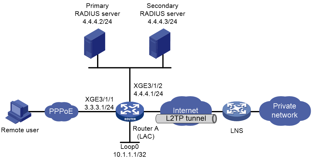
Analysis
· As an LAC, the BRAS does not need to configure DHCP. Its address will be assigned by the LNS after authentication.
· To ensure successful L2TP tunnel setup, make sure the RADIUS server assigns the following tunnel attributes:
¡ Tunnel-Type (attribute 64)—Protocol type of the tunnel. Value 3 represents L2TP.
¡ Tunnel-Medium-Type (attribute 65)—Medium type of the tunnel. Value 1 represents IPv4.
¡ Tunnel-Server-Endpoint (attribute 67)—Server endpoint IP address of the tunnel, that is, IP address of the LNS.
¡ Tunnel-Client-Auth-id (attribute 90)—Local tunnel name.
· In NAS-initiated mode, you must configure the triggering conditions for the LAC to initiate tunneling requests to the LNS.
Procedure
Configuring IP addresses and routes
# Create loopback interface LoopBack0 on the LAC, and assign IPv4 address 10.1.1.1/32 to the device.
<LAC> system-view
[LAC] interface loopback 0
[BRAS-LoopBack0] ip address 10.1.1.1 32
[BRAS-LoopBack0] quit
# Assign IPv4 address 3.3.3.1/24 to Ten-GigabitEthernet 3/1/1 on the LAC.
[LAC] interface ten-gigabitethernet 3/1/1
[LAC-Ten-GigabitEthernet3/1/1] ip address 3.3.3.1 24
[LAC-Ten-GigabitEthernet3/1/1] quit
# Assign IPv4 address 4.4.4.1/24 to Ten-GigabitEthernet 3/1/2 on the LAC.
[LAC] interface ten-gigabitethernet 3/1/2
[LAC-Ten-GigabitEthernet3/1/2] ip address 4.4.4.1 24
[LAC-Ten-GigabitEthernet3/1/2] quit
Configuring a RADIUS scheme
# Create RADIUS scheme rs1, and enter its view.
[LAC] radius scheme rs1
# Configure primary servers and keys for authentication and accounting.
[LAC-radius-rs1] primary authentication 4.4.4.2
[LAC-radius-rs1] primary accounting 4.4.4.2
[LAC-radius-rs1] secondary authentication 4.4.4.3
[LAC-radius-rs1] secondary accounting 4.4.4.3
[LAC-radius-rs1] key authentication simple 123456
[LAC-radius-rs1] key accounting simple 123456
# Enable interpreting RADIUS attribute 25 as CAR parameters.
[LAC-radius-rs1] attribute 25 car
# Configure the IPv4 NAS-IP address carried in RADIUS packets as 10.1.1.1, the IP address of interface Loopback 0.
[LAC-radius-rs1] nas-ip 10.1.1.1
# Exclude the ISP name from the username sent to the RADIUS server.
[LAC-radius-rs1] user-name-format without-domain
[LAC-radius-rs1] quit
Configuring the LAC
# Use RADIUS scheme rs1 for authentication, authorization, and accounting for PPP users in ISP domain md1.
[LAC] domain name dm1
[LAC-isp-dm1] authentication ppp radius-scheme rs1
[LAC-isp-dm1] authorization ppp radius-scheme rs1
[LAC-isp-dm1] accounting ppp radius-scheme rs1
# Enable the forcible use of RADIUS server-authorized L2TP attributes.
[LAC-isp-dm1] l2tp-user radius-force
# Allow users that encounter accounting-start failures to stay online. (The default configuration.)
[LAC-isp-dm1] accounting start-fail online
[LAC-isp-dm1] quit
# Configure Virtual-Template 1 to use PAP and CHAP for authenticating the peer.
[LAC] interface virtual-template 1
[LAC-Virtual-Template1] ppp authentication-mode pap chap domain default enable dm1
[LAC-Virtual-Template1] quit
# Enable the PPPoE server on interface Ten-GigabitEthernet 3/1/1, and bind the interface to Virtual-Template 1.
[LAC] interface ten-gigabitethernet 3/1/1
[LAC-Ten-GigabitEthernet3/1/1] pppoe-server bind virtual-template 1
[LAC-Ten-GigabitEthernet3/1/1] quit
# Enable L2TP.
[LAC] l2tp enable
# Configure L2TP group 1 in LAC mode. Configure the local tunnel name as LAC and configure the LAC to initiate an L2TP tunneling request to the LNS when the domain name of the access user matches the configured domain name.
[LAC] l2tp-group 1 mode lac
[LAC-l2tp1] tunnel name LAC
[LAC-l2tp1] user domain dm1
# Enable tunnel authentication, and set the tunnel authentication key to aabbcc.
[LAC-l2tp1] tunnel authentication
[LAC-l2tp1] tunnel password simple aabbcc
[LAC-l2tp1] quit
Configuring the LNS
|
|
IMPORTANT: The enterprise should complete the LNS configuration as required. The LNS configuration in this example is for illustration only. |
# Create a local PPP user named user1 and configure the password as pass1.
<LNS> system-view
[LNS] local-user user1 class network
[LNS-luser-network-user1] password simple pass1
[LNS-luser-network-user1] service-type ppp
[LNS-luser-network-user1] quit
# Enable DHCP.
[LNS] dhcp enable
# Configure local BAS IP address pool pool1.
[LNS] ip pool pool1 bas local
[LNS-ip-pool-pool1] gateway 192.168.0.1 24
[LNS-ip-pool-pool1] dns-list 8.8.8.8
# Exclude IP address 192.168.0.1 from dynamic address allocation in the address pool.
[LNS-ip-pool-pool1] forbidden-ip 192.168.0.1
[LNS-ip-pool-pool1] quit
# Configure DHCPv6 prefix pool 1 that contains prefix 2003::/48 and specify the length of prefixes to be assigned as 64.
[LNS] ipv6 dhcp prefix-pool 1 prefix 2003::/48 assign-len 64
# Create IPv6 address pool pool1, and reference prefix pool 1.
[LNS] ipv6 pool pool1
[LNS-ipv6-pool-pool1] prefix-pool 1 export-route
[LNS-ipv6-pool-pool1] quit
# Configure Virtual-Template 1 to use CHAP for authenticating the peer.
[LNS] interface virtual-template 1
[LNS-Virtual-Template1] ppp authentication-mode chap domain default enable dm1
# Disable RA message suppression and configure the interface to automatically generate a link-local address.
[LNS-Virtual-Template1] undo ipv6 nd ra halt
[LNS-Virtual-Template1] ipv6 address auto link-local
[LNS-Virtual-Template1] quit
# In ISP domain dm1, configure local AAA for PPP users and authorize an IPv4 address pool, ND prefix pool, and IPv6 DNS pool to the users.
[LNS] domain name dm1
[LNS-isp-dm1] authentication ppp local
[LNS-isp-dm1] accounting ppp local
[LNS-isp-dm1] authorization ppp local
[LNS-isp-dm1] authorization-attribute ip-pool pool1
[LNS-isp-dm1] authorization-attribute ipv6-nd-prefix-pool pool1
[LNS-isp-dm1] authorization-attribute primary-dns ipv6 8::8
[LNS-isp-dm1] quit
# Enable L2TP.
[LNS] l2tp enable
# Create L2TP group 1 in LNS mode. Configure the local tunnel name as LNS, and specify VT interface 1 for receiving calls from the peer (LAC) named LAC.
[LNS] l2tp-group 1 mode lns
[LNS-l2tp1] tunnel name LNS
[LNS-l2tp1] allow l2tp virtual-template 1 remote LAC
# Enable tunnel authentication, and set the tunnel authentication key to aabbcc.
[LNS-l2tp1] tunnel authentication
[LNS-l2tp1] tunnel password simple aabbcc
[LNS-l2tp1] quit
Configuring the RADIUS servers
|
|
IMPORTANT: This example uses the Srun software of version 4.1.0 to describe how to configure basic settings of the primary RADIUS server. Configure the secondary RADIUS server in the same way as the primary RADIUS server is configured. The actual configuration on a RADIUS server varies by software version. For more information about RADIUS server configuration, see the Srun server document of the corresponding version. This example is for illustration only. |
1. Add the access device:
a. Open a Web browser, and then enter http://4.4.4.2:8081 in the address bar to open the login page of the server.
b. Enter the account, password, and verification code, and click Login.
c. Click Device > Add Device.
d. Configure the following parameters and then click Save to add an access device:
- Device name—Enter the device name of the NAS (the device name is BRAS in this example).
- NAS IP—Enter the IP address of the NAS (10.1.1.1, the IP address of interface Loopback 0 on the BRAS device in this example).
- IP—Enter the IP address of the host where the Srun software is installed (4.4.4.2 in this example).
- NAS type—Specify the NAS type. Select Huawei, H3C, and Srun Gateways from the NAS type list.
- RADIUS key—Enter the key used for communication between the NAS and the RADIUS server (123456 in this example).
2. (Optional.) Add RADIUS attributes:
a. Click Radius > Add RADIUS Attributes to add RADIUS attributes.
This example adds the following attributes:
- Tunnel-Type (attribute 64)—Protocol type of the tunnel. Value 3 represents L2TP.
- Tunnel-Medium-Type (attribute 65)—Medium type of the tunnel. Value 1 represents IPv4.
- Tunnel-Server-Endpoint (attribute 67)—Server endpoint IP address of the tunnel, that is, IP address of the LNS.
- Tunnel-Client-Auth-id (attribute 90)—Local tunnel name.
b. Set the RADIUS trust.
Click Radius > Radius Trust Setting. Click Generate in the upper right corner until the trust is successfully generated.
c. Restart the RADIUS service
Restart the radiusd service to make the trust configuration take effect.
To re-enable the RADIUS service, access the CLI of the Srun server, execute the killall radiusd command to disable the RADIUS service and then execute the /srun3/radius/sbin/radiusd & command to enable the RADIUS service.
Figure 64 Restart the RADIUS service

3. Configure a user and related policies:
a. Open a Web browser, and then enter https://4.4.4.2:8080 to open the login page of the server.
b. Enter the account, password, and verification code, and click Login.
c. (Optional.) Create a control policy:
- From the left navigation pane, select Strategy > Control, and then click Add.
- Enter the policy name Custom Attributes. Select the added attributes in step 2 for the self-defined attributes field.
- Use default settings for other fields, and click Save.
d. (Optional.) Configure a product policy:
- Click Strategy > Product, and click Add.
- Enter User Policy in the Product Name field.
- Select Custom Attributes for the Control Strategy field.
e. Click Account > Add. Specify the account name and password for Host A. In this example, account name user1 and password pass1 are used.
f. (Optional.) Select the group for the user, and select User Policy.
g. Use default settings for other fields, and click Save.
Configuring the remote user
Configure PPPoE dial-up connection, and enter the username and password in the dial-up network window to initiate the dial-up process.
Verifying the configuration
After the dial-up connection is successfully established, the remote user will obtain a private IP address and will be able to ping the private IP address of the LNS.
Configuration files
· On LAC:
#
interface LoopBack 0
ip address 10.1.1.1 255.255.255.255
#
radius scheme rs1
primary authentication 4.4.4.2
primary accounting 4.4.4.2
secondary authentication 4.4.4.3
secondary accounting 4.4.4.3
key authentication cipher $c$3$RoKV2Xb9EYGE7/H939GdfTPBXc/J1DZeZg==
key accounting cipher $c$3$jw27tmAe7rB1tnuwDVQXyr8CGNK0Oovu+g==
user-name-format without-domain
nas-ip 10.1.1.1
attribute 25 car
#
domain name dm1
authentication ppp radius-scheme rs1
authorization ppp radius-scheme rs1
accounting ppp radius-scheme rs1
l2tp-user radius-force
#
interface virtual-template 1
ppp authentication-mode pap chap domain default enable dm1
#
interface ten-gigabitethernet 3/1/1
ip address 3.3.3.1 255.255.255.0
pppoe-server bind virtual-template 1
#
interface ten-gigabitethernet 3/1/2
ip address 4.4.4.1 255.255.255.0
#
l2tp enable
#
l2tp-group 1 mode lac
tunnel name LAC
user domain dm1
tunnel authentication
tunnel password simple aabbcc
· On LNS:
#
dhcp enable
#
ipv6 dhcp prefix-pool 1 prefix 2003::/48 assign-len 64
#
ip pool pool1 bas local
gateway 192.168.0.1 mask 255.255.255.0
dns-list 8.8.8.8
forbidden-ip 192.168.0.1
#
ipv6 pool pool1
prefix-pool 1 export-route
#
interface Virtual-Template1
ppp authentication-mode chap domain default enable dm1
ipv6 address auto link-local
undo ipv6 nd ra halt
#
domain name dm1
authorization-attribute ip-pool pool1
authorization-attribute ipv6-nd-prefix-pool pool1
authorization-attribute primary-dns ipv6 8::8
authentication ppp local
authorization ppp local
authentication ppp local
#
local-user user1 class network
password cipher $c$3$j72nKO8HmrgYqOyJbFTdusXraWeF/13u
service-type ppp
#
l2tp-group 1 mode lns
allow l2tp virtual-template 1 remote LAC
tunnel name LNS
tunnel password cipher $c$3$XJW2QCHxCUXHFN1tVYTLM7kn2acy434+XQ==
#
l2tp enable
#
L2TP LNS load sharing configuration example (tunnel attribute deployment by a RADIUS server)
Network configuration
A company has multiple remote devices in its offsite department that need to access the headquarters' LAN. The devices use PPPoE to connect to the LAC, and two L2TP tunnels are established between the LAC and LNSs for the following purposes:
· Users access the headquarters' LAN over the L2TP tunnels.
· For high availability and load sharing, configure the LAC to operate in load sharing mode to distribute L2TP services to the two LNSs.

Restrictions and guidelines
You can enable L2TP load balancing on the LAC by issuing tunnel attributes from a RADIUS server or executing L2TP commands at the CLI. This example uses a RADIUS server.
L2TP load balancing implemented through RADIUS server-based tunnel attribute deployment is available only to users who use the same username and password, and only 1:1 load balancing is supported.
Procedure
1. Configure IP addresses and routes:
# Assign IPv4 address 10.1.1.1/24 to Ten-GigabitEthernet 3/1/2 on the LAC.
<LAC> system-view
[LAC] interface ten-gigabitethernet 3/1/2
[LAC-Ten-GigabitEthernet3/1/2] ip address 10.1.1.1 24
[LAC-Ten-GigabitEthernet3/1/2] quit
# Assign IPv4 address 1.1.1.1/24 to Ten-GigabitEthernet 3/1/3 on the LAC.
[LAC] interface ten-gigabitethernet 3/1/3
[LAC-Ten-GigabitEthernet3/1/3] ip address 1.1.1.1 24
[LAC-Ten-GigabitEthernet3/1/3] quit
# Configure a static route to the LNS on the LAC.
[LAC] ip route-static 0.0.0.0 0 10.1.1.2
# Assign IPv4 address 20.1.1.2/24 to Ten-GigabitEthernet 3/1/1 on LNS1.
<LNS1> system-view
[LNS1] interface ten-gigabitethernet 3/1/1
[LNS1-Ten-GigabitEthernet3/1/1] ip address 20.1.1.2 24
[LNS1-Ten-GigabitEthernet3/1/1] quit
# Assign IPv4 address 10.2.2.2/24 to Ten-GigabitEthernet 3/1/2 on LNS1.
[LNS1] interface ten-gigabitethernet 3/1/2
[LNS1-Ten-GigabitEthernet3/1/2] ip address 10.2.2.2 24
[LNS1-Ten-GigabitEthernet3/1/2] quit
# Configure a static route to the LAC on LNS1.
[LNS1] ip route-static 0.0.0.0 0 20.1.1.1
# Assign IPv4 address 30.1.1.2/24 to Ten-GigabitEthernet 3/1/1 on LNS2.
<LNS2> system-view
[LNS2] interface ten-gigabitethernet 3/1/1
[LNS2-Ten-GigabitEthernet3/1/1] ip address 30.1.1.2 24
[LNS2-Ten-GigabitEthernet3/1/1] quit
# Assign IPv4 address 10.2.2.3/24 to Ten-GigabitEthernet 3/1/2 on LNS2.
[LNS2] interface ten-gigabitethernet 3/1/2
[LNS2-Ten-GigabitEthernet3/1/2] ip address 10.2.2.3 24
[LNS2-Ten-GigabitEthernet3/1/2] quit
# Configure a static route to the LAC on LNS2.
[LNS2] ip route-static 0.0.0.0 0 30.1.1.1
2. Configure the RADIUS server, Free RADIUS on Linux for example:
# Add RADIUS client information to the clients.conf file.
client 1.1.1.1/32 {
ipaddr = 1.1.1.1
netmask=32
secret = 123
}
# Add user validity information to the users file.
user1 Cleartext-Password := "pass1"
Service-Type = Framed-User,
Framed-Protocol = PPP,
Tunnel-Server-Endpoint:30 = "20.1.1.2 30.1.1.2",
Tunnel-Medium-Type:30 = IPv4,
Tunnel-Client-Auth-Id:30 = "LAC",
Tunnel-Type:30 = L2TP,
Tunnel-Password:30 = aabbcc,
When a L2TP user dials into the LAC with the username user1 and password pass1, the LAC sends the user's identity information to the RADIUS server as a RADIUS client for verification. The RADIUS server validates the L2TP user's identity and sends the verification result and corresponding L2TP tunnel attributes to the LAC. Based on the deployed tunnel attributes, the LAC creates the L2TP tunnels and session for the user. Table 5 shows the tunnel attributes.
Table 5 Tunnel attributes issued by the RADIUS server to the LAC
|
Attribute ID |
Attribute name |
Description |
|
64 |
Tunnel-Type |
Tunnel type. Only the L2TP tunnel type is supported. |
|
65 |
Tunnel-Medium-Type |
Tunnel medium type. Only IPv4 is supported. |
|
67 |
Tunnel-Server-Endpoint |
LNS IP address. 1:1 load sharing is performed if multiple IP addresses are configured. |
|
69 |
Tunnel-Password |
Tunnel password. |
|
90 |
Tunnel-Client-Auth-Id |
LAC-end tunnel name to identify a local tunnel. |
3. Configure the LAC:
# Create RADIUS scheme rs1 and enter its view.
[LAC] radius scheme rs1
# Specify the primary authentication and accounting server.
[LAC-radius-rs1] primary authentication 1.1.1.2
[LAC-radius-rs1] primary accounting 1.1.1.2
[LAC-radius-rs1] key authentication simple 123
[LAC-radius-rs1] key accounting simple 123
# Exclude domain names from the usernames sent to the RADIUS server.
[LAC-radius-rs1] user-name-format without-domain
[LAC-radius-rs1] quit
# Apply RADIUS scheme rs1 to PPP users in the ISP domain dm1.
[LAC] domain name dm1
[LAC-isp-dm1] authentication ppp radius-scheme rs1
[LAC-isp-dm1] accounting ppp radius-scheme rs1
[LAC-isp-dm1] authorization ppp radius-scheme rs1
# Configure the device to allow users that encounter accounting-start failures to stay online. (The default setting.)
[LAC-isp-dm1] accounting start-fail online
[LAC-isp-dm1] quit
# Create interface Virtual-Template 1. Configure Virtual-Template 1 to use PAP for authentication.
[LAC] interface virtual-template 1
[LAC-Virtual-Template1] ppp authentication-mode pap domain dm1
[LAC-Virtual-Template1] quit
# Enable a PPPoE server on Ten-GigabitEthernet 3/1/1 and bind Ten-GigabitEthernet 3/1/1 to interface Virtual-Template 1.
[LAC] interface ten-gigabitethernet 3/1/1
[LAC-Ten-GigabitEthernet3/1/1] pppoe-server bind virtual-template 1
[LAC-Ten-GigabitEthernet3/1/1] quit
# Enable L2TP.
[LAC] l2tp enable
4. Configure LNS1:
|
|
NOTE: Typically, the LNSs are configured by the company's administrator. The following information is only for demonstration. |
# Create local PPP user user1 and set its password to pass1.
[LNS1] local-user user1 class network
[LNS1-luser-network-user1] password simple pass1
[LNS1-luser-network-user1] service-type ppp
[LNS1-luser-network-user1] quit
# Enable the DHCP service.
[LNS1] dhcp enable
# Enable recording client information in relay entries.
[LNS1] dhcp relay client-information record
# Create remote BAS IP pool pool1. Specify a gateway for DHCPv4 clients, exclude the gateway address from IP allocation, and specify a DHCP server address.
[LNS1] ip pool pool1 bas remote
[LNS1-ip-pool-pool1] gateway 192.168.1.1 25
[LNS1-ip-pool-pool1] forbidden-ip 192.168.1.1
[LNS1-ip-pool-pool1] remote-server 10.2.2.1
[LNS1-ip-pool-pool1] quit
# Configure ISP domain dm1 to use local AAA schemes for authentication, authorization, and accounting for PPP users, and specify an authorization address pool.
[LNS1] domain name dm1
[LNS1-isp-dm1] authentication ppp local
[LNS1-isp-dm1] accounting ppp local
[LNS1-isp-dm1] authorization ppp local
[LNS1-isp-dm1] authorization-attribute ip-pool pool1
[LNS1-isp-dm1] quit
#Create interface Virtual-Template 1, and configure it to use PAP for PPP authentication.
[LNS1] interface virtual-template 1
[LNS1-virtual-template1] ppp authentication-mode pap domain dm1
[LNS1-virtual-template1] quit
# Enable L2TP.
[LNS1] l2tp enable
# Create L2TP group 1 in LNS mode, configure the local tunnel name as LNS1, and specify Virtual-Template 1 for receiving calls from the specified LAC.
[LNS1] l2tp-group 1 mode lns
[LNS1-l2tp1] tunnel name LNS1
[LNS1-l2tp1] allow l2tp virtual-template 1 remote LAC
# Enable tunnel authentication, and set the tunnel password to aabbcc.
[LNS1-l2tp1] tunnel authentication
[LNS1-l2tp1] tunnel password simple aabbcc
[LNS1-l2tp1] quit
5. Configure LNS2:
|
|
NOTE: Typically, the LNSs are configured by the company's administrator. The following information is only for demonstration. |
# Create local PPP user user1 and set its password to pass1.
[LNS2] local-user user1 class network
[LNS2-luser-network-user1] password simple pass1
[LNS2-luser-network-user1] service-type ppp
[LNS2-luser-network-user1] quit
# Enable the DHCP service.
[LNS2] dhcp enable
# Enable recording client information in relay entries.
[LNS2] dhcp relay client-information record
# Create remote BAS IP pool pool2. Specify a gateway for DHCPv4 clients, exclude the gateway address from IP allocation, and specify a DHCP server address.
[LNS2] ip pool pool2 bas remote
[LNS2-ip-pool-pool2] gateway 192.168.1.129 25
[LNS2-ip-pool-pool2] forbidden-ip 192.168.1.129
[LNS2-ip-pool-pool2] remote-server 10.2.2.1
[LNS2-ip-pool-pool2] quit
# Configure ISP domain dm1 to use local AAA schemes for authentication, authorization, and accounting for PPP users, and specify an authorization address pool.
[LNS2] domain name dm1
[LNS2-isp-dm1] authentication ppp local
[LNS2-isp-dm1] accounting ppp local
[LNS2-isp-dm1] authorization ppp local
[LNS2-isp-dm1] authorization-attribute ip-pool pool2
[LNS2-isp-dm1] quit
#Create interface Virtual-Template 1, and configure it to use PAP for PPP authentication.
[LNS2] interface virtual-template 1
[LNS2-virtual-template1] ppp authentication-mode pap domain dm1
[LNS2-virtual-template1] quit
# Enable L2TP.
[LNS2] l2tp enable
# Create L2TP group 1 in LNS mode, configure the local tunnel name as LNS2, and specify Virtual-Template 1 for receiving calls from the specified LAC.
[LNS2] l2tp-group 1 mode lns
[LNS2-l2tp1] tunnel name LNS2
[LNS2-l2tp1] allow l2tp virtual-template 1 remote LAC
# Enable tunnel authentication, and set the tunnel password to aabbcc.
[LNS2-l2tp1] tunnel authentication
[LNS2-l2tp1] tunnel password simple aabbcc
[LNS2-l2tp1] quit
6. Configure a DHCP server:
# Enable DHCP.
<DHCP> system-view
[DHCP] dhcp enable
# Create DHCP pool pool1.
[DHCP] ip pool pool1
[DHCP-ip-pool-pool1] network 192.168.1.0 25
[DHCP-ip-pool-pool1] gateway-list 192.168.1.1
[DHCP-ip-pool-pool1] dns-list 8.8.8.8
# Exclude 192.168.1.1 from IP allocation.
[DHCP-ip-pool-pool1] forbidden-ip 192.168.1.1
[DHCP-ip-pool-pool1] quit
# Create DHCP pool pool2.
[DHCP] ip pool pool2
[DHCP-ip-pool-pool2] network 192.168.1.128 25
[DHCP-ip-pool-pool2] gateway-list 192.168.1.129
[DHCP-ip-pool-pool2] dns-list 8.8.8.8
# Exclude 192.168.1.129 from IP allocation.
[DHCP-ip-pool-pool2] forbidden-ip 192.168.1.129
[DHCP-ip-pool-pool2] quit
# Configure static routes to the LAC.
[DHCP] ip route-static 192.168.1.0 255.255.255.128 10.2.2.2
[DHCP] ip route-static 192.168.1.128 255.255.255.128 10.2.2.3
7. On the remote hosts, enter user1 as the username and pass1 as the password in the dial-up network window to dial a PPPoE connection.
Verifying the configuration
# Verify that host A, host B, and host C have obtained IP addresses 192.168.1.2, 192.168.1.130, and 192.168.1.3, respectively, and they can ping the private gateway in the headquarters.
# Verify that the LNSs have established three L2TP sessions.
[LNS1] display l2tp session
LocalSID RemoteSID LocalTID State
Username
49545 10341 22365 Established
user1
24517 50848 22365 Established
user1
[LNS2] display l2tp session
LocalSID RemoteSID LocalTID State
Username
21869 45683 29701 Established
user1
# Verify that the LAC has established two L2TP tunnels.
[LAC] display l2tp tunnel
LocalTID RemoteTID State Sessions RemoteAddress RemotePort
RemoteName
2349 22365 Established 2 20.1.1.2 1701
LNS1
47731 29701 Established 1 30.1.1.2 1701
LNS2
Configuration files
· LAC:
#
interface Virtual-Template1
ppp authentication-mode pap domain dm1
#
interface ten-gigabitethernet3/1/1
pppoe-server bind virtual-template 1
pppoe-server access-line-id content all
#
interface ten-gigabitethernet3/1/2
ip address 10.1.1.1 255.255.255.0
#
interface ten-gigabitethernet3/1/3
ip address 1.1.1.1 255.255.255.0
#
ip route-static 0.0.0.0 0 10.1.1.2
#
radius scheme rs1
primary authentication 1.1.1.2
primary accounting 1.1.1.2
key authentication cipher $c$3$JWv9UgkAq9zqCA/zIgiY+2CNEa/y5w==
key accounting cipher $c$3$G+VGeU3QNguXqt2JfJhppzWUI/9S5w==
user-name-format without-domain
#
l2tp enable
· LNS1:
#
dhcp enable
#
local-user user1 class network
password simple pass1
service-type ppp
#
ip pool pool1 bas remote
gateway 192.168.1.1 mask 255.255.255.128
forbidden-ip 192.168.1.1
remote-server 10.2.2.1
#
interface Virtual-Template1
ppp authentication-mode pap domain dm1
#
interface ten-gigabitethernet3/1/1
ip address 20.1.1.2 255.255.255.0
#
interface ten-gigabitethernet3/1/2
ip address 10.2.2.2 255.255.255.0
#
ip route-static 0.0.0.0 0 20.1.1.1
#
domain name dm1
authentication ppp local
accounting ppp local
authorization ppp local
authorization-attribute ip-pool pool1
#
l2tp-group 1 mode lns
allow l2tp virtual-template 1 remote LAC
tunnel authentication
tunnel password simple aabbcc
tunnel name LNS
#
l2tp enable
· LNS2:
#
dhcp enable
#
local-user user1 class network
password simple pass1
service-type ppp
#
ip pool pool2 bas remote
gateway 192.168.1.129 mask 255.255.255.128
forbidden-ip 192.168.1.129
remote-server 10.2.2.1
#
interface Virtual-Template1
ppp authentication-mode pap domain dm1
#
interface ten-gigabitethernet3/1/1
ip address 30.1.1.2 255.255.255.0
#
interface ten-gigabitethernet3/1/2
ip address 10.2.2.3 255.255.255.0
#
ip route-static 0.0.0.0 0 30.1.1.1
#
domain name dm1
authentication ppp local
accounting ppp local
authorization ppp local
authorization-attribute ip-pool pool2
#
l2tp-group 1 mode lns
allow l2tp virtual-template 1 remote LAC
tunnel authentication
tunnel password simple aabbcc
tunnel name LNS
#
l2tp enable
· DHCP server:
#
dhcp enable
#
ip pool pool1
gateway-list 192.168.1.1
network 192.168.1.0 mask 255.255.255.128
forbidden-ip 192.168.1.1
#
ip pool pool2
gateway-list 192.168.1.128
network 192.168.1.129 mask 255.255.255.128
forbidden-ip 192.168.1.129
#
interface ten-gigabitethernet3/1/1
ip address 10.2.2.1 255.255.255.0
#
ip route-static 192.168.1.0 25 10.2.2.2
ip route-static 192.168.1.128 25 10.2.2.3
L2TP LNS load sharing configuration example (CLI configuration)
Network configuration
A company has multiple remote devices in its offsite department that need to access the headquarters' LAN. The devices use PPPoE to connect to the LAC, and two L2TP tunnels are established between the LAC and LNSs for the following purposes:
· Users access the headquarters' LAN over the L2TP tunnels.
· For high availability and load sharing, configure the LAC to operate in load sharing mode to distribute L2TP services to the two LNSs.
Figure 66 Network diagram
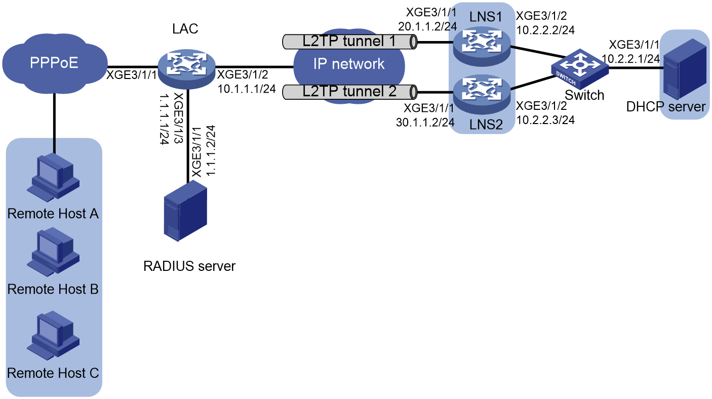
Restrictions and guidelines
You can enable L2TP load balancing on the LAC by issuing tunnel attributes from a RADIUS server or executing L2TP commands at the CLI. This example uses the CLI configuration.
Procedure
1. Configure IP addresses and routes:
# Assign IPv4 address 10.1.1.1/24 to Ten-GigabitEthernet 3/1/2 on the LAC.
<LAC> system-view
[LAC] interface ten-gigabitethernet 3/1/2
[LAC-Ten-GigabitEthernet3/1/2] ip address 10.1.1.1 24
[LAC-Ten-GigabitEthernet3/1/2] quit
# Assign IPv4 address 1.1.1.1/24 to Ten-GigabitEthernet 3/1/3 on the LAC.
[LAC] interface ten-gigabitethernet 3/1/3
[LAC-Ten-GigabitEthernet3/1/3] ip address 1.1.1.1 24
[LAC-Ten-GigabitEthernet3/1/3] quit
# Configure a static route to the LNS on the LAC.
[LAC] ip route-static 0.0.0.0 0 10.1.1.2
# Assign IPv4 address 20.1.1.2/24 to Ten-GigabitEthernet 3/1/1 on LNS1.
<LNS1> system-view
[LNS1] interface ten-gigabitethernet 3/1/1
[LNS1-Ten-GigabitEthernet3/1/1] ip address 20.1.1.2 24
[LNS1-Ten-GigabitEthernet3/1/1] quit
# Assign IPv4 address 10.2.2.2/24 to Ten-GigabitEthernet 3/1/2 on LNS1.
[LNS1] interface ten-gigabitethernet 3/1/2
[LNS1-Ten-GigabitEthernet3/1/2] ip address 10.2.2.2 24
[LNS1-Ten-GigabitEthernet3/1/2] quit
# Configure a static route to the LAC on LNS1.
[LNS1] ip route-static 0.0.0.0 0 20.1.1.1
# Assign IPv4 address 30.1.1.2/24 to Ten-GigabitEthernet 3/1/1 on LNS2.
<LNS2> system-view
[LNS2] interface ten-gigabitethernet 3/1/1
[LNS2-Ten-GigabitEthernet3/1/1] ip address 30.1.1.2 24
[LNS2-Ten-GigabitEthernet3/1/1] quit
# Assign IPv4 address 10.2.2.3/24 to Ten-GigabitEthernet 3/1/2 on LNS2.
[LNS2] interface ten-gigabitethernet 3/1/2
[LNS2-Ten-GigabitEthernet3/1/2] ip address 10.2.2.3 24
[LNS2-Ten-GigabitEthernet3/1/2] quit
# Configure a static route to the LAC on LNS2.
[LNS2] ip route-static 0.0.0.0 0 30.1.1.1
2. Configure the RADIUS server, Free RADIUS on Linux for example:
# Add RADIUS client information to the clients.conf file.
client 1.1.1.1/32 {
ipaddr = 1.1.1.1
netmask=32
secret = 123
}
# Add user validity information to the users file.
user1 Cleartext-Password := "pass1"
Service-Type = Framed-User,
Framed-Protocol = PPP,
When an L2TP user dials into the LAC with the username user1 and password pass1, the LAC sends the user's identity information to the RADIUS server as a RADIUS client for verification.
3. Configure the LAC:
# Create RADIUS scheme rs1 and enter its view.
[LAC] radius scheme rs1
# Specify the primary authentication and accounting server.
[LAC-radius-rs1] primary authentication 1.1.1.2
[LAC-radius-rs1] primary accounting 1.1.1.2
[LAC-radius-rs1] key authentication simple 123
[LAC-radius-rs1] key accounting simple 123
# Exclude domain names from the usernames sent to the RADIUS server.
[LAC-radius-rs1] user-name-format without-domain
[LAC-radius-rs1] quit
# Apply RADIUS scheme rs1 to PPP users in the ISP domain dm1.
[LAC] domain name dm1
[LAC-isp-dm1] authentication ppp radius-scheme rs1
[LAC-isp-dm1] accounting ppp radius-scheme rs1
[LAC-isp-dm1] authorization ppp radius-scheme rs1
# Configure the device to allow users that encounter accounting-start failures to stay online. (The default setting.)
[LAC-isp-dm1] accounting start-fail online
[LAC-isp-dm1] quit
# Create interface Virtual-Template 1. Configure Virtual-Template 1 to use PAP for authentication.
[LAC] interface virtual-template 1
[LAC-Virtual-Template1] ppp authentication-mode pap domain dm1
[LAC-Virtual-Template1] quit
# Enable a PPPoE server on Ten-GigabitEthernet 3/1/1 and bind Ten-GigabitEthernet 3/1/1 to interface Virtual-Template 1.
[LAC] interface ten-gigabitethernet 3/1/1
[LAC-Ten-GigabitEthernet3/1/1] pppoe-server bind virtual-template 1
[LAC-Ten-GigabitEthernet3/1/1] quit
# Enable L2TP.
[LAC] l2tp enable
# Create L2TP group 1 in LAC mode, and configure the local tunnel name as LAC. Configure the LAC to initiate tunneling requests to the LNS when the domain name of a user matches the configured domain name.
[LAC] l2tp-group 1 mode lac
[LAC-l2tp1] tunnel name LAC
[LAC-l2tp1] user domain dm1
# Configure the LAC to operate in load sharing mode, and configure LNS IP addresses 20.1.1.2 and 30.1.1.2 with a weight of 1:1.
[LAC-l2tp1] tunnel load-sharing
[LAC-l2tp1] lns-ip 20.1.1.2 weight 1 30.1.1.2 weight 1
# Enable tunnel authentication and set the tunnel password to aabbcc.
[LAC-l2tp1] tunnel authentication
[LAC-l2tp1] tunnel password simple aabbcc
4. Configure LNS1:
|
|
NOTE: Typically, the LNSs are configured by the company's administrator. The following information is only for demonstration. |
# Create local PPP user user1 and set its password to pass1.
[LNS1] local-user user1 class network
[LNS1-luser-network-user1] password simple pass1
[LNS1-luser-network-user1] service-type ppp
[LNS1-luser-network-user1] quit
# Enable the DHCP service.
[LNS1] dhcp enable
# Enable recording client information in relay entries.
[LNS1] dhcp relay client-information record
# Create remote BAS IP pool pool1. Specify a gateway for DHCPv4 clients, exclude the gateway address from IP allocation, and specify a DHCP server address.
[LNS1] ip pool pool1 bas remote
[LNS1-ip-pool-pool1] gateway 192.168.1.1 25
[LNS1-ip-pool-pool1] forbidden-ip 192.168.1.1
[LNS1-ip-pool-pool1] remote-server 10.2.2.1
[LNS1-ip-pool-pool1] quit
# Configure ISP domain dm1 to use local AAA schemes for authentication, authorization, and accounting for PPP users, and specify an authorization address pool.
[LNS1] domain name dm1
[LNS1-isp-dm1] authentication ppp local
[LNS1-isp-dm1] accounting ppp local
[LNS1-isp-dm1] authorization ppp local
[LNS1-isp-dm1] authorization-attribute ip-pool pool1
[LNS1-isp-dm1] quit
#Create interface Virtual-Template 1, and configure it to use PAP for PPP authentication.
[LNS1] interface virtual-template 1
[LNS1-virtual-template1] ppp authentication-mode pap domain dm1
[LNS1-virtual-template1] quit
# Enable L2TP.
[LNS1] l2tp enable
# Create L2TP group 1 in LNS mode, configure the local tunnel name as LNS1, and specify Virtual-Template 1 for receiving calls from the specified LAC.
[LNS1] l2tp-group 1 mode lns
[LNS1-l2tp1] tunnel name LNS1
[LNS1-l2tp1] allow l2tp virtual-template 1 remote LAC
# Enable tunnel authentication, and set the tunnel password to aabbcc.
[LNS1-l2tp1] tunnel authentication
[LNS1-l2tp1] tunnel password simple aabbcc
[LNS1-l2tp1] quit
5. Configure LNS2:
|
|
NOTE: Typically, the LNSs are configured by the company's administrator. The following information is only for demonstration. |
# Create local PPP user user1 and set its password to pass1.
[LNS2] local-user user1 class network
[LNS2-luser-network-user1] password simple pass1
[LNS2-luser-network-user1] service-type ppp
[LNS2-luser-network-user1] quit
# Enable the DHCP service.
[LNS2] dhcp enable
# Enable recording client information in relay entries.
[LNS2] dhcp relay client-information record
# Create remote BAS IP pool pool2. Specify a gateway for DHCPv4 clients, exclude the gateway address from IP allocation, and specify a DHCP server address.
[LNS2] ip pool pool2 bas remote
[LNS2-ip-pool-pool2] gateway 192.168.1.129 25
[LNS2-ip-pool-pool2] forbidden-ip 192.168.1.129
[LNS2-ip-pool-pool2] remote-server 10.2.2.1
[LNS2-ip-pool-pool2] quit
# Configure ISP domain dm1 to use local AAA schemes for authentication, authorization, and accounting for PPP users, and specify an authorization address pool.
[LNS2] domain name dm1
[LNS2-isp-dm1] authentication ppp local
[LNS2-isp-dm1] accounting ppp local
[LNS2-isp-dm1] authorization ppp local
[LNS2-isp-dm1] authorization-attribute ip-pool pool2
[LNS2-isp-dm1] quit
#Create interface Virtual-Template 1, and configure it to use PAP for PPP authentication.
[LNS2] interface virtual-template 1
[LNS2-virtual-template1] ppp authentication-mode pap domain dm1
[LNS2-virtual-template1] quit
# Enable L2TP.
[LNS2] l2tp enable
# Create L2TP group 1 in LNS mode, configure the local tunnel name as LNS2, and specify Virtual-Template 1 for receiving calls from the specified LAC.
[LNS2] l2tp-group 1 mode lns
[LNS2-l2tp1] tunnel name LNS2
[LNS2-l2tp1] allow l2tp virtual-template 1 remote LAC
# Enable tunnel authentication, and set the tunnel password to aabbcc.
[LNS2-l2tp1] tunnel authentication
[LNS2-l2tp1] tunnel password simple aabbcc
[LNS2-l2tp1] quit
6. Configure a DHCP server:
# Enable DHCP.
<DHCP> system-view
[DHCP] dhcp enable
# Create DHCP pool pool1.
[DHCP] ip pool pool1
[DHCP-ip-pool-pool1] network 192.168.1.0 25
[DHCP-ip-pool-pool1] gateway-list 192.168.1.1
[DHCP-ip-pool-pool1] dns-list 8.8.8.8
# Exclude 192.168.1.1 from IP allocation.
[DHCP-ip-pool-pool1] forbidden-ip 192.168.1.1
[DHCP-ip-pool-pool1] quit
# Create DHCP pool pool2.
[DHCP] ip pool pool2
[DHCP-ip-pool-pool2] network 192.168.1.128 25
[DHCP-ip-pool-pool2] gateway-list 192.168.1.129
[DHCP-ip-pool-pool2] dns-list 8.8.8.8
# Exclude 192.168.1.129 from IP allocation.
[DHCP-ip-pool-pool2] forbidden-ip 192.168.1.129
[DHCP-ip-pool-pool2] quit
# Configure static routes to the LAC.
[DHCP] ip route-static 192.168.1.0 255.255.255.128 10.2.2.2
[DHCP] ip route-static 192.168.1.128 255.255.255.128 10.2.2.3
7. On the remote hosts, enter user1 as the username and pass1 as the password in the dial-up network window to dial a PPPoE connection.
Verifying the configuration
# Verify that host A, host B, and host C have obtained IP addresses 192.168.1.2, 192.168.1.130, and 192.168.1.3, respectively, and they can ping the private gateway in the headquarters.
# Verify that the LNSs have established three L2TP sessions.
[LNS1] display l2tp session
LocalSID RemoteSID LocalTID State
Username
49545 10341 22365 Established
user1
24517 50848 22365 Established
user1
[LNS2] display l2tp session
LocalSID RemoteSID LocalTID State
Username
21869 45683 29701 Established
user1
# Verify that the LAC has established two L2TP tunnels.
[LAC] display l2tp tunnel
LocalTID RemoteTID State Sessions RemoteAddress RemotePort
RemoteName
2349 22365 Established 2 20.1.1.2 1701
LNS1
47731 29701 Established 1 30.1.1.2 1701
LNS2
Configuration files
· LAC:
#
interface Virtual-Template1
ppp authentication-mode pap domain dm1
#
interface ten-gigabitethernet3/1/1
pppoe-server bind virtual-template 1
pppoe-server access-line-id content all
#
interface ten-gigabitethernet3/1/2
ip address 10.1.1.1 255.255.255.0
#
interface ten-gigabitethernet3/1/3
ip address 1.1.1.1 255.255.255.0
#
ip route-static 0.0.0.0 0 10.1.1.2
#
radius scheme rs1
primary authentication 1.1.1.2
primary accounting 1.1.1.2
key authentication cipher $c$3$JWv9UgkAq9zqCA/zIgiY+2CNEa/y5w==
key accounting cipher $c$3$G+VGeU3QNguXqt2JfJhppzWUI/9S5w==
user-name-format without-domain
#
l2tp enable
#
l2tp-group 1 mode lac
lns-ip 20.1.1.2 weight 1 30.1.1.2 weight 1
user domain dm1
tunnel load-sharing
tunnel name LAC
tunnel password cipher $c$3$jrqJ35EadbdxEjRXyw4TwuUWEk6/Guc11g==
#
· LNS1:
#
dhcp enable
#
local-user user1 class network
password simple pass1
service-type ppp
#
ip pool pool1 bas remote
gateway 192.168.1.1 mask 255.255.255.128
forbidden-ip 192.168.1.1
remote-server 10.2.2.1
#
interface Virtual-Template1
ppp authentication-mode pap domain dm1
#
interface ten-gigabitethernet3/1/1
ip address 20.1.1.2 255.255.255.0
#
interface ten-gigabitethernet3/1/2
ip address 10.2.2.2 255.255.255.0
#
ip route-static 0.0.0.0 0 20.1.1.1
#
domain name dm1
authentication ppp local
accounting ppp local
authorization ppp local
authorization-attribute ip-pool pool1
#
l2tp-group 1 mode lns
allow l2tp virtual-template 1 remote LAC
tunnel authentication
tunnel password simple aabbcc
tunnel name LNS
#
l2tp enable
· LNS2:
#
dhcp enable
#
local-user user1 class network
password simple pass1
service-type ppp
#
ip pool pool2 bas remote
gateway 192.168.1.129 mask 255.255.255.128
forbidden-ip 192.168.1.129
remote-server 10.2.2.1
#
interface Virtual-Template1
ppp authentication-mode pap domain dm1
#
interface ten-gigabitethernet3/1/1
ip address 30.1.1.2 255.255.255.0
#
interface ten-gigabitethernet3/1/2
ip address 10.2.2.3 255.255.255.0
#
ip route-static 0.0.0.0 0 30.1.1.1
#
domain name dm1
authentication ppp local
accounting ppp local
authorization ppp local
authorization-attribute ip-pool pool2
#
l2tp-group 1 mode lns
allow l2tp virtual-template 1 remote LAC
tunnel authentication
tunnel password simple aabbcc
tunnel name LNS
#
l2tp enable
· DHCP server:
#
dhcp enable
#
ip pool pool1
gateway-list 192.168.1.1
network 192.168.1.0 mask 255.255.255.128
forbidden-ip 192.168.1.1
#
ip pool pool2
gateway-list 192.168.1.128
network 192.168.1.129 mask 255.255.255.128
forbidden-ip 192.168.1.129
#
interface ten-gigabitethernet3/1/1
ip address 10.2.2.1 255.255.255.0
#
ip route-static 192.168.1.0 25 10.2.2.2
ip route-static 192.168.1.128 25 10.2.2.3
Configuring IPv6 user access through PPPoE in the 6vPE scenario
6vPE indicates IPv6 MPLS L3VPN. Figure 67 shows a typical configuration example. In a 6vPE network, the service provider adopts an IPv4 network for the backbone. IPv6 is used inside each VPN and between CEs and PEs. In the backbone, IPv4 is used between PEs and Ps. The PEs are required to support both IPv4 and IPv6. A PE uses IPv6 on the interface connected to a CE, and uses IPv4 on the interface connected to the backbone.
Upon receiving an IPv6 route from a CE, the PE assigns a private network label to the route, and advertises the private network label and the IPv6 route to the remote PE through a VPNv6 route. When forwarding an IPv6 packet through the IPv4 backbone, the PE encapsulates a private network label to the packet, so that the IPv6 packet can be transparently transmitted through the IPv4 network. In this way, communication between IPv6 networks through an IPv4 network is implemented.
Figure 67 6vPE application network diagram
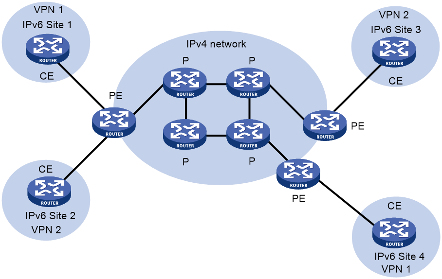
Network configuration
As shown in Figure 68:
· CE 1 and CE 3 belong to VPN 1. CE 2 and CE 4 belong to VPN 2.
· The Route Target attributes used by VPN 1 and VPN 2 are 111:1 and 222:2, respectively. Users in different VPNs cannot access each other.
· Configure EBGP to exchange VPN routing information between CEs and PEs.
Configure OSPF for communication between PEs, and configure MP-IBGP to exchange VPN routing information between them.
IPv6 user endpoint Host connects to PE 1 through CE 2. After CE 2 initiates a PPPoE connection as a PPPoE client, PE 1 acting as a PPPoE server assigns a PD prefix to CE 1 through DHCPv6. CE 1 then assigns an IPv6 address to the attached host through the PD prefix. After passing authentication, the host can access VPN devices at the same site.
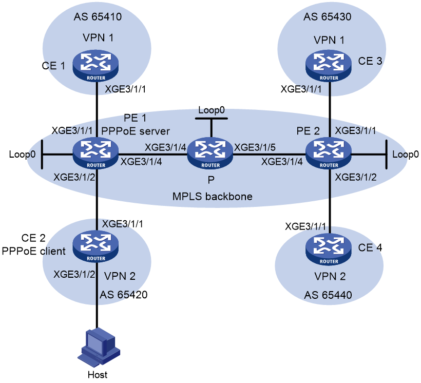
Table 6 Interface and IP address assignment
|
Device |
Interface |
IP address |
Device |
Interface |
IP address |
|
CE 1 |
XGE3/1/1 |
2001:1::1/64 |
P |
Loop0 |
2.2.2.9/32 |
|
PE 1 |
Loop0 |
1.1.1.9/32 |
|
XGE3/1/4 |
10.1.1.2/24 |
|
|
XGE3/1/1 |
2001:1::2/64 |
|
XGE3/1/5 |
10.2.1.1/24 |
|
|
XGE3/1/2 |
2001:2::2/64 |
PE 2 |
Loop0 |
3.3.3.9/32 |
|
|
XGE3/1/4 |
10.1.1.1/24 |
|
XGE3/1/1 |
2001:3::2/64 |
|
CE 2 |
XGE3/1/1 |
2001:2::1/64 |
|
XGE3/1/2 |
2001:4::2/64 |
|
CE 3 |
XGE3/1/1 |
2001:3::1/64 |
|
XGE3/1/4 |
10.2.1.2/24 |
|
CE 4 |
XGE3/1/1 |
2001:4::1/64 |
|
|
|
Analysis
· To implement user access, configure PPPoE access settings on PE 1.
· To implement communication between PEs and Ps, configure IGP for the MPLS backbone.
· For PE 1, P, and PE 2 to establish LDP sessions, enable MPLS and MPLS LDP for the MPLS backbone.
· For CE to access PE, configure IPv6 VPN instances on PEs.
· Create EBGP peers between PE and CE to import VPN routes.
· Create MP-IBGP peers between PEs to exchange routing information.
Prerequisites
Configure IPv6 addresses and IPv4 addresses for the interfaces.
Procedure
Configuring IGP for the MPLS backbone to implement communication between PEs and P
# Configure PE 1.
<PE1> system-view
[PE1] interface loopback 0
[PE1-LoopBack0] ip address 1.1.1.9 32
[PE1-LoopBack0] quit
[PE1] interface ten-gigabitethernet 3/1/4
[PE1-Ten-GigabitEthernet3/1/4] ip address 10.1.1.1 24
[PE1-Ten-GigabitEthernet3/1/4] quit
[PE1] ospf
[PE1-ospf-1] area 0
[PE1-ospf-1-area-0.0.0.0] network 10.1.1.0 0.0.0.255
[PE1-ospf-1-area-0.0.0.0] network 1.1.1.9 0.0.0.0
[PE1-ospf-1-area-0.0.0.0] quit
[PE1-ospf-1] quit
# Configure P.
<P> system-view
[P] interface loopback 0
[P-LoopBack0] ip address 2.2.2.9 32
[P-LoopBack0] quit
[P] interface ten-gigabitethernet 3/1/4
[P-Ten-GigabitEthernet3/1/4] ip address 10.1.1.2 24
[P-Ten-GigabitEthernet3/1/4] quit
[P] interface ten-gigabitethernet 3/1/5
[P-Ten-GigabitEthernet3/1/5] ip address 10.2.1.1 24
[P-Ten-GigabitEthernet3/1/5] quit
[P] ospf
[P-ospf-1] area 0
[P-ospf-1-area-0.0.0.0] network 10.1.1.0 0.0.0.255
[P-ospf-1-area-0.0.0.0] network 10.2.1.0 0.0.0.255
[P-ospf-1-area-0.0.0.0] network 2.2.2.9 0.0.0.0
[P-ospf-1-area-0.0.0.0] quit
[P-ospf-1] quit
# Configure PE 2.
<PE2> system-view
[PE2] interface loopback 0
[PE2-LoopBack0] ip address 3.3.3.9 32
[PE2-LoopBack0] quit
[PE2] interface ten-gigabitethernet 3/1/4
[PE2-Ten-GigabitEthernet3/1/4] ip address 10.2.1.2 24
[PE2-Ten-GigabitEthernet3/1/4] quit
[PE2] ospf
[PE2-ospf-1] area 0
[PE2-ospf-1-area-0.0.0.0] network 10.2.1.0 0.0.0.255
[PE2-ospf-1-area-0.0.0.0] network 3.3.3.9 0.0.0.0
[PE2-ospf-1-area-0.0.0.0] quit
[PE2-ospf-1] quit
Configuring MPLS basic capability and MPLS LDP for the MPLS backbone to establish LDP LSPs
# Configure PE 1.
[PE1] mpls lsr-id 1.1.1.9
[PE1] mpls ldp
[PE1-ldp] quit
[PE1] interface ten-gigabitethernet 3/1/4
[PE1-Ten-GigabitEthernet3/1/4] mpls enable
[PE1-Ten-GigabitEthernet3/1/4] mpls ldp enable
[PE1-Ten-GigabitEthernet3/1/4] quit
# Configure P.
[P] mpls lsr-id 2.2.2.9
[P] mpls ldp
[P-ldp] quit
[P] interface ten-gigabitethernet 3/1/4
[P-Ten-GigabitEthernet3/1/4] mpls enable
[P-Ten-GigabitEthernet3/1/4] mpls ldp enable
[P-Ten-GigabitEthernet3/1/4] quit
[P] interface ten-gigabitethernet 3/1/5
[P-Ten-GigabitEthernet3/1/5] mpls enable
[P-Ten-GigabitEthernet3/1/5] mpls ldp enable
[P-Ten-GigabitEthernet3/1/5] quit
# Configure PE 2.
[PE2] mpls lsr-id 3.3.3.9
[PE2] mpls ldp
[PE2-ldp] quit
[PE2] interface ten-gigabitethernet 3/1/4
[PE2-Ten-GigabitEthernet3/1/4] mpls enable
[PE2-Ten-GigabitEthernet3/1/4] mpls ldp enable
[PE2-Ten-GigabitEthernet3/1/4] quit
Configuring IPv6 VPN instances on PEs for CEs to access PEs, and configuring interface IP addresses for CEs
# Configure PE 1.
[PE1] ip vpn-instance vpn1
[PE1-vpn-instance-vpn1] route-distinguisher 100:1
[PE1-vpn-instance-vpn1] vpn-target 111:1
[PE1-vpn-instance-vpn1] quit
[PE1] ip vpn-instance vpn2
[PE1-vpn-instance-vpn2] route-distinguisher 100:2
[PE1-vpn-instance-vpn2] vpn-target 222:2
[PE1-vpn-instance-vpn2] quit
[PE1] interface ten-gigabitethernet 3/1/1
[PE1-Ten-GigabitEthernet3/1/1] ip binding vpn-instance vpn1
[PE1-Ten-GigabitEthernet3/1/1] ipv6 address 2001:1::2 64
[PE1-Ten-GigabitEthernet3/1/1] quit
[PE1] interface ten-gigabitethernet 3/1/2
[PE1-Ten-GigabitEthernet3/1/2] ip binding vpn-instance vpn2
[PE1-Ten-GigabitEthernet3/1/2] ipv6 address 2001:2::2 64
[PE1-Ten-GigabitEthernet3/1/2] quit
# Configure PE 2.
[PE2] ip vpn-instance vpn1
[PE2-vpn-instance-vpn1] route-distinguisher 200:1
[PE2-vpn-instance-vpn1] vpn-target 111:1
[PE2-vpn-instance-vpn1] quit
[PE2] ip vpn-instance vpn2
[PE2-vpn-instance-vpn2] route-distinguisher 200:2
[PE2-vpn-instance-vpn2] vpn-target 222:2
[PE2-vpn-instance-vpn2] quit
[PE2] interface ten-gigabitethernet 3/1/1
[PE2-Ten-GigabitEthernet3/1/1] ip binding vpn-instance vpn1
[PE2-Ten-GigabitEthernet3/1/1] ipv6 address 2001:3::2 64
[PE2-Ten-GigabitEthernet3/1/1] quit
[PE2] interface ten-gigabitethernet 3/1/2
[PE2-Ten-GigabitEthernet3/1/2] ip binding vpn-instance vpn2
[PE2-Ten-GigabitEthernet3/1/2] ipv6 address 2001:4::2 64
[PE2-Ten-GigabitEthernet3/1/2] quit
# Configure the interface IP address for CE 1.
<CE1> system
[CE1] interface ten-gigabitethernet 3/1/1
[CE1-Ten-GigabitEthernet3/1/1] ipv6 address 2001:1::1 64
[CE1-Ten-GigabitEthernet3/1/1] quit
# Configure the interface IP address for CE 2.
<CE2> system
[CE2] interface ten-gigabitethernet 3/1/1
[CE2-Ten-GigabitEthernet3/1/1] ipv6 address 2001:2::1 64
[CE2-Ten-GigabitEthernet3/1/1] quit
# Configure the interface IP address for CE 3.
<CE3> system
[CE3] interface ten-gigabitethernet 3/1/1
[CE3-Ten-GigabitEthernet3/1/1] ipv6 address 2001:3::1 64
[CE3-Ten-GigabitEthernet3/1/1] quit
# Configure the interface IP address for CE 4.
<CE4> system
[CE4] interface ten-gigabitethernet 3/1/1
[CE4-Ten-GigabitEthernet3/1/1] ipv6 address 2001:4::1 64
[CE4-Ten-GigabitEthernet3/1/1] quit
Creating EBGP peers between PEs and CEs to import VPN routes
# Configure CE 1.
[CE1] bgp 65410
[CE1-bgp-default] peer 2001:1::2 as-number 100
[CE1-bgp-default] address-family ipv6 unicast
[CE1-bgp-default-ipv6] peer 2001:1::2 enable
[CE1-bgp-default-ipv6] import-route direct
[CE1-bgp-default-ipv6] quit
[CE1-bgp-default] quit
# Configure CE 2.
[CE1] bgp 65420
[CE1-bgp-default] peer 2001:2::2 as-number 100
[CE1-bgp-default] address-family ipv6 unicast
[CE1-bgp-default-ipv6] peer 2001:2::2 enable
[CE1-bgp-default-ipv6] import-route direct
[CE1-bgp-default-ipv6] quit
[CE1-bgp-default] quit
# Configure CE 3.
[CE1] bgp 65430
[CE1-bgp-default] peer 2001:3::2 as-number 100
[CE1-bgp-default] address-family ipv6 unicast
[CE1-bgp-default-ipv6] peer 2001:3::2 enable
[CE1-bgp-default-ipv6] import-route direct
[CE1-bgp-default-ipv6] quit
[CE1-bgp-default] quit
# Configure CE 4.
[CE1] bgp 65440
[CE1-bgp-default] peer 2001:4::2 as-number 100
[CE1-bgp-default] address-family ipv6 unicast
[CE1-bgp-default-ipv6] peer 2001:4::2 enable
[CE1-bgp-default-ipv6] import-route direct
[CE1-bgp-default-ipv6] quit
[CE1-bgp-default] quit
# Configure PE 1.
[PE1] bgp 100
[PE1-bgp-default] ip vpn-instance vpn1
[PE1-bgp-default-vpn1] peer 2001:1::1 as-number 65410
[PE1-bgp-default-vpn1] address-family ipv6 unicast
[PE1-bgp-default-ipv6-vpn1] peer 2001:1::1 enable
[PE1-bgp-default-ipv6-vpn1] quit
[PE1-bgp-default-vpn1] quit
[PE1-bgp-default] ip vpn-instance vpn2
[PE1-bgp-default-vpn2] peer 2001:2::1 as-number 65420
[PE1-bgp-default-vpn2] address-family ipv6 unicast
[PE1-bgp-default-ipv6-vpn2] peer 2001:2::1 enable
[PE1-bgp-default-ipv6-vpn2] quit
[PE1-bgp-default-vpn2] quit
[PE1-bgp-default] quit
# Configure PE 2.
[PE1] bgp 100
[PE1-bgp-default] ip vpn-instance vpn1
[PE1-bgp-default-vpn1] peer 2001:3::1 as-number 65430
[PE1-bgp-default-vpn1] address-family ipv6 unicast
[PE1-bgp-default-ipv6-vpn1] peer 2001:3::1 enable
[PE1-bgp-default-ipv6-vpn1] quit
[PE1-bgp-default-vpn1] quit
[PE1-bgp-default] ip vpn-instance vpn2
[PE1-bgp-default-vpn2] peer 2001:4::1 as-number 65440
[PE1-bgp-default-vpn2] address-family ipv6 unicast
[PE1-bgp-default-ipv6-vpn2] peer 2001:4::1 enable
[PE1-bgp-default-ipv6-vpn2] quit
[PE1-bgp-default-vpn2] quit
[PE1-bgp-default] quit
Creating MP-IBGP peers between PEs
# Configure PE 1.
[PE1] bgp 100
[PE1-bgp-default] peer 3.3.3.9 as-number 100
[PE1-bgp-default] peer 3.3.3.9 connect-interface loopback 0
[PE1-bgp-default] address-family vpnv6
[PE1-bgp-default-vpnv6] peer 3.3.3.9 enable
[PE1-bgp-default-vpnv6] quit
[PE1-bgp-default] quit
# Configure PE 2.
[PE2] bgp 100
[PE2-bgp-default] peer 1.1.1.9 as-number 100
[PE2-bgp-default] peer 1.1.1.9 connect-interface loopback 0
[PE2-bgp-default] address-family vpnv6
[PE2-bgp-default-vpnv6] peer 1.1.1.9 enable
[PE2-bgp-default-vpnv6] quit
[PE2-bgp-default] quit
Configuring PPPoE server settings on PE 1
# Configure Virtual-Template 1 to use CHAP for authenticating the peer.
<PE1> system-view
[PE1] interface virtual-template 1
[PE1-Virtual-Template1] ppp authentication-mode chap domain default enable dm1
# Disable RA message suppression.
[PE1-Virtual-Template1] undo ipv6 nd ra halt
[PE1-Virtual-Template1] quit
# Configure interface Ten-GigabitEthernet 3/1/2 to automatically generate a link-local address.
[PE1] interface ten-gigabitethernet 3/1/2
[PE1-Ten-GigabitEthernet3/1/2] ipv6 address auto link-local
# Disable RA message suppression.
[PE1-Ten-GigabitEthernet3/1/2] undo ipv6 nd ra halt
# Enable the DHCPv6 server on the interface.
[PE1-Ten-GigabitEthernet3/1/2] ipv6 dhcp select server
# Enable the PPPoE server on Ten-GigabitEthernet 3/1/2, and bind it to Virtual-Template 1.
[PE1-Ten-GigabitEthernet3/1/2] pppoe-server bind virtual-template 1
# Specify ISP domain dm1 as the roaming domain on Ten-GigabitEthernet 3/1/2. The device uses the roaming domain to authenticate a user if the user is assigned to the ISP domain carried in the username but the assigned domain does not exist.
[PE1-Ten-GigabitEthernet3/1/2] aaa roam-domain dm1
[PE1-Ten-GigabitEthernet3/1/2] quit
# Configure DHCPv6 prefix pool 6 that contains prefix 2003::/32 and specify the assigned prefix length as 42.
[PE1] ipv6 dhcp prefix-pool 6 prefix 2003::/32 assign-len 42
# Create IPv6 address pool pool1, and specify prefix pool 6 for it.
[PE1] ipv6 pool pool1
[PE1-ipv6-pool-pool1] prefix-pool 6 export-route
[PE1-ipv6-pool-pool1] quit
# Configure a PPPoE user.
[PE1] local-user user1 class network
[PE1-luser-network-user1] password simple 123456TESTplat&!
[PE1-luser-network-user1] service-type ppp
[PE1-luser-network-user1] quit
# In ISP domain dm1, configure local AAA for users and authorize an IPv6 address pool.
[PE1] domain name dm1
[PE1-isp-dm1] authentication ppp local
[PE1-isp-dm1] accounting ppp local
[PE1-isp-dm1] authorization ppp local
[PE1-isp-dm1] authorization-attribute ipv6-pool pool1
[PE1-isp-dm1] quit
Configure PPPoE client settings on CE 2
|
|
NOTE: · The device (PE 1 in this example) can only act as a PPPoE server, and cannot act as a PPPoE client. · The configuration for the device acting as the PPPoE client varies by version. The configuration in this section is for illustration only. For more information, see the manual for the device acting as the PPPoE client. |
# Enable bundle DDR on interface Dialer 1.
[CE2] interface dialer 1
[CE2-Dialer1] dialer bundle enable
# On Dialer 1, configure the CHAP username and password sent from CE 2 to PE 1 as user1 and 123456TESTplat&! when CE 2 is authenticated by PE 1 by using CHAP.
[CE2-Dialer1] ppp chap user user1
[CE2-Dialer1] ppp chap password simple 123456TESTplat&!
# Configure the PPPoE client to operate in permanent mode.
[CE2-Dialer1] dialer timer idle 0
# Configure the auto-dial timer as 60 seconds for DDR.
[CE2-Dialer1] dialer timer autodial 60
# Configure interface Dialer 1 to use DHCPv6 to obtain an IPv6 address and other configuration parameters.
[CE2-Dialer1] ipv6 address dhcp-alloc
# Configure interface Dialer 1 as a DHCPv6 client for IPv6 prefix acquisition. Configure the DHCPv6 client to assign ID 1 to the obtained IPv6 prefix.
[CE2-Dialer1] ipv6 dhcp client pd 1
[CE2-Dialer1] quit
# Configure a PPPoE session and specify dialer bundle 1 (which corresponds to interface Dialer 1) for the session.
[CE2] interface ten-gigabitethernet 3/1/1
[CE2-Ten-GigabitEthernet3/1/1] pppoe-client dial-bundle-number 1
[CE2-Ten-GigabitEthernet3/1/1] quit
# Configuring a default route.
[CE2] ipv6 route-static :: 0 dialer 1
# Disable RA message suppression on Ten-GigabitEthernet 3/1/2.
[CE2] interface ten-gigabitethernet 3/1/2
[CE2-Ten-GigabitEthernet3/1/2] undo ipv6 nd ra halt
# Configure Ten-GigabitEthernet 3/1/2 to dynamically obtain IPv6 prefix 1 (use IPv6 prefix 1 to generate IPv6 address 2003::123:1:1, which must be configured as the gateway address for the user attached to CE 2) and advertise IPv6 prefix 1 to endpoints through RA messages.
[CE2-Ten-GigabitEthernet3/1/2] ipv6 address 1 123::123:1:1/64
[CE2-Ten-GigabitEthernet3/1/2] quit
Verifying the configuration
# On the PE, execute the display ipv6 routing-table vpn-instance command to view the routes to the peer CEs.
Take PE 1 as an example:
[PE1] display ipv6 routing-table vpn-instance vpn1
Destinations : 5 Routes : 5
Destination: ::1/128 Protocol : Direct
NextHop : ::1 Preference: 0
Interface : InLoop0 Cost : 0
Destination: 2001:1::/64 Protocol : Direct
NextHop : :: Preference: 0
Interface : XGE3/1/1 Cost : 0
Destination: 2001:1::2/128 Protocol : Direct
NextHop : ::1 Preference: 0
Interface : InLoop0 Cost : 0
Destination: 2001:3::/64 Protocol : BGP4+
NextHop : ::FFFF:3.3.3.9 Preference: 255
Interface : XGE3/1/4 Cost : 0
Destination: FE80::/10 Protocol : Direct
NextHop : :: Preference: 0
Interface : NULL0 Cost : 0
[PE1] display ipv6 routing-table vpn-instance vpn2
Destinations : 5 Routes : 5
Destination: ::1/128 Protocol : Direct
NextHop : ::1 Preference: 0
Interface : InLoop0 Cost : 0
Destination: 2001:2::/64 Protocol : Direct
NextHop : :: Preference: 0
Interface : XGE3/1/2 Cost : 0
Destination: 2001:2::2/128 Protocol : Direct
NextHop : ::1 Preference: 0
Interface : InLoop0 Cost : 0
Destination: 2001:4::/64 Protocol : BGP4+
NextHop : ::FFFF:3.3.3.9 Preference: 255
Interface : XGE3/1/4 Cost : 0
Destination: FE80::/10 Protocol : Direct
NextHop : :: Preference: 0
Interface : NULL0 Cost : 0
CEs in the same VPN can ping each other. CEs in different VPNs cannot ping each other. For example, CE 1 and ping CE 3 (2001:3::1), but it cannot ping CE 4 (2001:4::1).
After the configuration is completed, when CE 2 uses username user1 and password 123456TESTplat&! to access PE 1 through PPPoE, PE 1 assigns a PD prefix to CE 2 through DHCPv6.
# Display binding information for the assigned IPv6 prefixes.
[PE1] display ipv6 dhcp server pd-in-use
Pool: pool1
IPv6 prefix Type Lease expiration
2003::/42 Auto(C) Jul 10 19:45:01 2019
The output shows that PE 1 assigns a PD prefix to CE 2 through DHCPv6.
# Display information about IPv6 prefixes created on CE 2.
[CE1] display ipv6 prefix
Number Prefix Type
1 2003::/42 Dynamic
The output shows that after CE 2 obtains a PD prefix from PE 1, CE 2 creates an IPv6 prefix with ID 1 according to the ipv6 dhcp client pd 1 command.
Then, CE 2 can assign prefix 2003::/42 to the host who uses the prefix to generate an IPv6 global unicast address.
Configuration files
· CE 1:
#
sysname CE1
#
interface Ten-GigabitEthernet3/1/1
ipv6 address 2001:1::1/64
#
bgp 65410
peer 2001:1::2 as-number 100
#
address-family ipv6 unicast
import-route direct
peer 2001:1::2 enable
#
· CE 2:
#
sysname CE2
#
interface Dialer1
ppp chap password cipher $c$3$VITzjOQfYsmmIo5b+Fw9ta24zEmKC6PM2hL7X5RpWJixbQg=
ppp chap user user1
dialer bundle enable
dialer timer idle 0
dialer timer autodial 60
ipv6 address dhcp-alloc
ipv6 dhcp client pd 1
#
interface Ten-GigabitEthernet3/1/1
ipv6 address 2001:2::1/64
pppoe-client dial-bundle-number 1
#
interface Ten-GigabitEthernet3/1/2
ipv6 address 1 123::123:1:1/64
undo ipv6 nd ra halt
#
bgp 65420
peer 2001:2::2 as-number 100
#
address-family ipv6 unicast
import-route direct
peer 2001:2::2 enable
#
ipv6 route-static :: 0 Dialer1
#
· CE 3:
#
sysname CE3
#
interface Ten-GigabitEthernet3/1/1
ipv6 address 2001:3::1/64
#
bgp 65430
peer 2001:3::2 as-number 100
#
address-family ipv6 unicast
import-route direct
peer 2001:3::2 enable
#
· CE 4:
#
sysname CE4
#
system-working-mode standard
xbar load-single
password-recovery enable
lpu-type f-series
#
interface Ten-GigabitEthernet3/1/1
ipv6 address 2001:4::1/64
#
bgp 65440
peer 2001:4::2 as-number 100
#
address-family ipv6 unicast
import-route direct
peer 2001:4::2 enable
#
· PE 1:
#
sysname PE1
#
ip vpn-instance vpn1
route-distinguisher 100:1
vpn-target 111:1 import-extcommunity
vpn-target 111:1 export-extcommunity
#
ip vpn-instance vpn2
route-distinguisher 100:2
vpn-target 222:2 import-extcommunity
vpn-target 222:2 export-extcommunity
#
ospf 1
area 0.0.0.0
network 1.1.1.9 0.0.0.0
network 10.1.1.0 0.0.0.255
#
mpls lsr-id 1.1.1.9
#
ipv6 dhcp prefix-pool 6 prefix 2003::/32 assign-len 42
#
ipv6 pool pool1
prefix-pool 6 export-route
#
mpls ldp
#
interface Virtual-Template1
ppp authentication-mode chap domain default enable dm1
undo ipv6 nd ra halt
#
interface LoopBack0
ip address 1.1.1.9 255.255.255.255
#
interface Ten-GigabitEthernet3/1/1
ip binding vpn-instance vpn1
ipv6 address 2001:1::2/64
#
interface Ten-GigabitEthernet3/1/2
aaa roam-domain dm1
ip binding vpn-instance vpn2
ipv6 dhcp select server
ipv6 address 2001:2::2/64
ipv6 address auto link-local
undo ipv6 nd ra halt
pppoe-server bind virtual-template 1
#
interface Ten-GigabitEthernet3/1/4
ip address 10.1.1.1 255.255.255.0
mpls enable
mpls ldp enable
#
bgp 100
peer 3.3.3.9 as-number 100
peer 3.3.3.9 connect-interface LoopBack0
#
address-family vpnv6
peer 3.3.3.9 enable
#
ip vpn-instance vpn1
peer 2001:1::1 as-number 65410
#
address-family ipv6 unicast
peer 2001:1::1 enable
#
ip vpn-instance vpn2
peer 2001:2::1 as-number 65420
#
address-family ipv6 unicast
peer 2001:2::1 enable
#
domain name dm1
authorization-attribute ipv6-pool pool1
authentication ppp local
authorization ppp local
accounting ppp local
#
local-user user1 class network
password cipher $c$3$nFfy12Sn41nTawPtSdpUMOwx0kjvzW7r1XzvKgVXqodMz+s=
service-type ppp
#
· PE 2:
#
sysname PE2
#
ip vpn-instance vpn1
route-distinguisher 200:1
vpn-target 111:1 import-extcommunity
vpn-target 111:1 export-extcommunity
#
ip vpn-instance vpn2
route-distinguisher 200:2
vpn-target 222:2 import-extcommunity
vpn-target 222:2 export-extcommunity
#
ospf 1
area 0.0.0.0
network 3.3.3.9 0.0.0.0
network 10.2.1.0 0.0.0.255
#
mpls lsr-id 3.3.3.9
#
mpls ldp
#
interface LoopBack0
ip address 3.3.3.9 255.255.255.255
#
interface Ten-GigabitEthernet3/1/1
ip binding vpn-instance vpn1
ipv6 address 2001:3::2/64
#
interface Ten-GigabitEthernet3/1/2
ip binding vpn-instance vpn2
ipv6 address 2001:4::2/64
#
interface Ten-GigabitEthernet3/1/4
ip address 10.2.1.2 255.255.255.0
mpls enable
mpls ldp enable
#
bgp 100
peer 1.1.1.9 as-number 100
peer 1.1.1.9 connect-interface LoopBack0
#
address-family vpnv6
peer 1.1.1.9 enable
#
ip vpn-instance vpn1
peer 2001:3::1 as-number 65430
#
address-family ipv6 unicast
peer 2001:3::1 enable
#
ip vpn-instance vpn2
peer 2001:4::1 as-number 65440
#
· P:
#
sysname P
#
ospf 1
area 0.0.0.0
network 2.2.2.9 0.0.0.0
network 10.1.1.0 0.0.0.255
network 10.2.1.0 0.0.0.255
#
mpls lsr-id 2.2.2.9
#
mpls ldp
#
interface LoopBack0
ip address 2.2.2.9 255.255.255.255
#
interface Ten-GigabitEthernet3/1/4
ip address 10.1.1.2 255.255.255.0
mpls enable
mpls ldp enable
#
interface Ten-GigabitEthernet3/1/5
ip address 10.2.1.1 255.255.255.0
mpls enable
mpls ldp enable
#
Configuring IPv6 user access through PPPoE in the 6PE scenario
For an IPv4 backbone deployed with MPLS, the ISP can use the IPv6 Provider Edge (6PE) technology to provide connectivity between dispersed IPv6 user networks.
Figure 69 shows mechanism for connecting IPv6 customer sites through 6PEs.
· Upon receiving an IPv6 packet from a CE, 6PE adds a label to convert the IPv6 packet into an MPLS packet that can be forwarded in the IPv4 backbone.
· The MPLS packet is forwarded to the peer 6PE through an LSP.
· The peer 6PE removes the label, and performs an IPv6 routing table lookup based on the destination address in the original IPv6 packet.
· The packet is forwarded to the destination host in the peer IPv6 network through the peer CE.
Figure 69 6PE operating mechanism
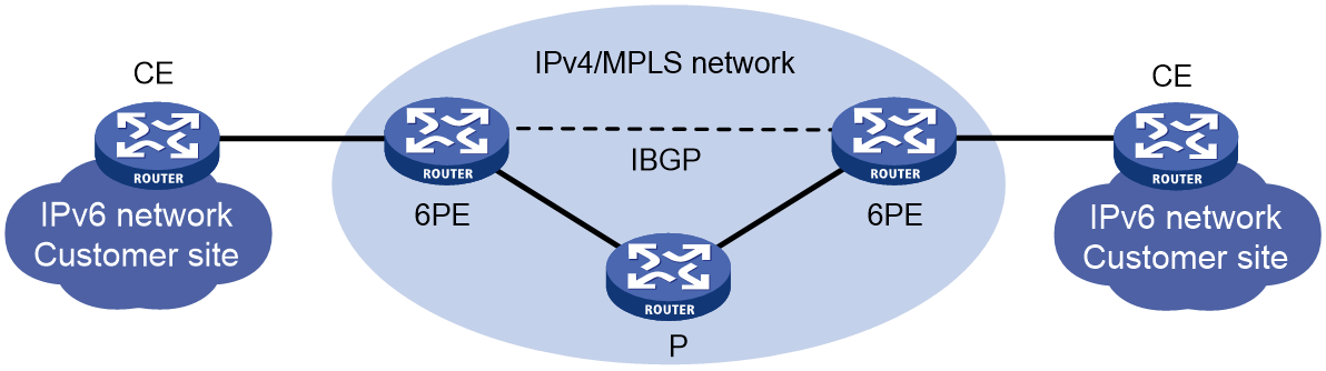
When you connect IPv6 customer sites through 6PEs, follow these guidelines:
· You need to enable IPv4, MPLS, and IPv6 on 6PEs.
· Enable MP-BGP between 6PEs, so that they can send and receive IPv6 routes from each other.
· The IGP in the ISP’s IPv4 backbone can be OSPF or IS-IS.
· You can configure static routes, IGP, or EBGP between CEs and 6PEs.
Network configuration
As shown in Figure 70, CE 1 and CE 2 reside in IPv6 networks. The PEs reside in the ISP’s IPv4/MPLS network. Use the 6PE feature to enable Host attached to CE 1 to communicate with CE 2 in a different IPv6 network across the IPv4/MPLS network.
IPv6 user endpoint Host connects to PE 1 through CE 1. After CE 1 initiates a PPPoE connection as a PPPoE client, PE 1 acting as a PPPoE server assigns a PD prefix to CE 1 through DHCPv6. CE 1 then assigns an IPv6 address to the attached host through the PD prefix. After the host passes authentication, user packets must traverse the IPv4/MPLS backbone to the reach the pure IPv6 network. PE 1 acts as a 6PE converts IPv6 packets into MPLS packets that can be transmitted on the IPv4 backbone. The packets are then forwarded to PE2 (another 6PE) through an LSP. PE 2 removes label, and performs an IPv6 routing table lookup based on the destination address in the original IPv6 packets. In this way, CE 1 and CE 2 can communicate over the IPv4 network.
· The ISP network uses OSPF as the IGP.
· PE 1 and PE 2 are edge devices of the ISP network. They establish an IPv4 IBGP connection.
· CE 1 and CE 2 are edge devices of the IPv6 user networks. They connect the IPv6 user networks to the ISP network.
· Configure IPv6 static routes between the CEs and PEs to guide IPv6 packet forwarding.
· CE 1 acts as a PPPoE client, and PE 1 acts as a PPPoE server.
· In this example, the PPPoE server adopts the local authentication mode.
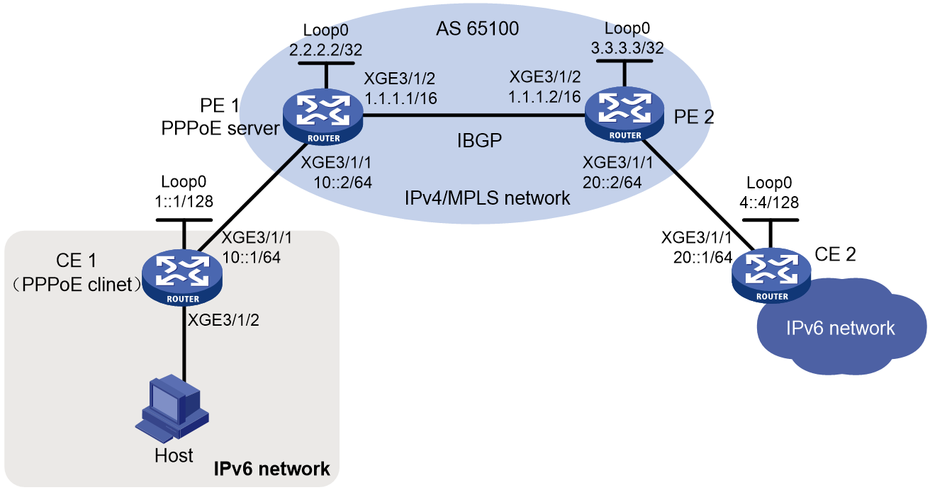
Analysis
· To implement user access, configure PPPoE user access settings on PE1.
· For PE 1 and PE 2 to learn the loopback interface `IP addresses of each other, configure OSPF on PE 1 and PE 2.
· For PE 1 and PE 2 to establish an LDP LSP, enable MPLS and MPLS LDP for the backbone.
· Create 6PE peers between PE 1 and PE 2.
· Configure static routes between PE 1 and CE 1 and between PE 2 and CE 2.
Prerequisites
Configure IPv6 addresses and IPv4 addresses for the interfaces. (Details not shown.)
Procedure
Configuring PE 1
# For PE 1 and PE 2 to establish an LDP LSP, enable MPLS and MPLS LDP for the backbone.
# Enable the LDP capability globally, and configure an LSP generation policy.
<PE1> system-view
[PE1] mpls lsr-id 2.2.2.2
[PE1] mpls ldp
[PE1-ldp] quit
# Enable MPLS and LDP capabilities for interface Ten-GigabitEthernet 3/1/2.
[PE1] interface ten-gigabitethernet 3/1/2
[PE1-Ten-GigabitEthernet3/1/2] mpls enable
[PE1-Ten-GigabitEthernet3/1/2] mpls ldp enable
[PE1-Ten-GigabitEthernet3/1/2] quit
Creating 6PE peers between PE 1 and PE 2
# Configure IBGP, enable the 6PE capabilities for the peers, and redistribute IPv6 direct route, static routes, and PPPoE users’ UNR routes.
[PE1] bgp 65100
[PE1-bgp-default] router-id 2.2.2.2
[PE1-bgp-default] peer 3.3.3.3 as-number 65100
[PE1-bgp-default] peer 3.3.3.3 connect-interface loopback 0
[PE1-bgp-default] address-family ipv6
[PE1-bgp-default-ipv6] import-route direct
[PE1-bgp-default-ipv6] import-route static
[PE1-bgp-default-ipv6] import-route unr
[PE1-bgp-default-ipv6] peer 3.3.3.3 enable
[PE1-bgp-default-ipv6] peer 3.3.3.3 label-route-capability
[PE1-bgp-default-ipv6] quit
[PE1-bgp-default] quit
Configuring static routes for communication between PE 1 and CE 1
# Configure static routes to CE 1.
[PE1] ipv6 route-static 1::1 128 10::1
[PE1] ipv6 route-static 2003:: 42 10::1
Configuring OSPF for PE 1 and PE 2 to learn the loopback interface routes of each other
# Configure OSPF for communication within the ISP network.
[PE1] ospf
[PE1-ospf-1] area 0
[PE1-ospf-1-area-0.0.0.0] network 2.2.2.2 0.0.0.0
[PE1-ospf-1-area-0.0.0.0] network 1.1.0.0 0.0.255.255
[PE1-ospf-1-area-0.0.0.0] quit
[PE1-ospf-1] quit
Configuring PPPoE server settings on PE 1
# Configure Virtual-Template 1 to use CHAP for authenticating the peer.
<PE1> system-view
[PE1] interface virtual-template 1
[PE1-Virtual-Template1] ppp authentication-mode chap domain default enable dm1
# Disable RA message suppression.
[PE1-Virtual-Template1] undo ipv6 nd ra halt
[PE1-Virtual-Template1] quit
# Configure interface Ten-GigabitEthernet 3/1/1 to automatically generate a link-local address.
[PE1] interface ten-gigabitethernet 3/1/1
[PE1-Ten-GigabitEthernet3/1/1] ipv6 address auto link-local
# Disable RA message suppression.
[PE1-Ten-GigabitEthernet3/1/1] undo ipv6 nd ra halt
# Enable the DHCPv6 server on the interface.
[PE1-Ten-GigabitEthernet3/1/1] ipv6 dhcp select server
# Enable the PPPoE server on Ten-GigabitEthernet 3/1/1, and bind it to Virtual-Template 1.
[PE1-Ten-GigabitEthernet3/1/1] pppoe-server bind virtual-template 1
# Specify ISP domain dm1 as the roaming domain on Ten-GigabitEthernet 3/1/1. The device uses the roaming domain to authenticate a user if the user is assigned to the ISP domain carried in the username but the assigned domain does not exist.
[PE1-Ten-Gigabitethernet3/1/1] aaa roam-domain dm1
[PE1-Ten-GigabitEthernet3/1/1] quit
# Configure DHCPv6 prefix pool 6 that contains prefix 2003::/32 and specify the assigned prefix length as 42.
[PE1] ipv6 dhcp prefix-pool 6 prefix 2003::/32 assign-len 42
# Create IPv6 address pool pool1, and specify prefix pool 6 for it.
[PE1] ipv6 pool pool1
[PE1-ipv6-pool-pool1] prefix-pool 6 export-route
[PE1-ipv6-pool-pool1] quit
# Configure a PPPoE user.
[PE1] local-user user1 class network
[PE1-luser-network-user1] password simple 123456TESTplat&!
[PE1-luser-network-user1] service-type ppp
[PE1-luser-network-user1] quit
# In ISP domain dm1, configure local AAA for users and authorize an IPv6 address pool.
[PE1] domain name dm1
[PE1-isp-dm1] authentication ppp local
[PE1-isp-dm1] accounting ppp local
[PE1-isp-dm1] authorization ppp local
[PE1-isp-dm1] authorization-attribute ipv6-pool pool1
[PE1-isp-dm1] quit
Configure PE 2:
# For PE 1 and PE 2 to establish an LDP LSP, enable MPLS and MPLS LDP for the backbone.
# Enable the LDP capability globally, and configure an LSP generation policy.
<PE2> system-view
[PE2] mpls lsr-id 3.3.3.3
[PE2] mpls ldp
[PE2-mpls-ldp] quit
# Enable MPLS and LDP capabilities for interface Ten-GigabitEthernet 3/1/2.
[PE2] interface ten-gigabitethernet 3/1/2
[PE2-Ten-GigabitEthernet3/1/2] mpls enable
[PE2-Ten-GigabitEthernet3/1/2] mpls ldp enable
[PE2-Ten-GigabitEthernet3/1/2] quit
Creating 6PE peers between PE 1 and PE 2
# Configure IBGP, enable the 6PE capabilities for the peers, and redistribute IPv6 direct and static routes.
[PE2] bgp 65100
[PE2-bgp-default] router-id 3.3.3.3
[PE2-bgp-default] peer 2.2.2.2 as-number 65100
[PE2-bgp-default] peer 2.2.2.2 connect-interface loopback 0
[PE2-bgp-default] address-family ipv6
[PE2-bgp-default-ipv6] import-route direct
[PE2-bgp-default-ipv6] import-route static
[PE2-bgp-default-ipv6] peer 2.2.2.2 enable
[PE2-bgp-default-ipv6] peer 2.2.2.2 label-route-capability
[PE2-bgp-default-ipv6] quit
[PE2-bgp-default] quit
Configuring a static route for communication between PE 2 and CE 2
# Configure a static route to CE 2.
[PE2] ipv6 route-static 4::4 128 20::1
Configuring OSPF for PE 1 and PE 2 to learn the loopback interface routes of each other
# Configure OSPF for communication within the ISP.
[PE2] ospf
[PE2-ospf-1] area 0
[PE2-ospf-1-area-0.0.0.0] network 3.3.3.3 0.0.0.0
[PE2-ospf-1-area-0.0.0.0] network 1.1.0.0 0.0.255.255
[PE2-ospf-1-area-0.0.0.0] quit
[PE2-ospf-1] quit
Configuring CE 1
|
|
NOTE: · The device (PE 1 in this example) can only act as a PPPoE server, and cannot act as a PPPoE client. · The configuration for the device acting as the PPPoE client varies by version. The configuration in this section is for illustration only. For more information, see the manual for the device acting as the PPPoE client. |
# Enable bundle DDR on interface Dialer 1.
<CE1> system-view
[CE1] interface dialer 1
[CE1-Dialer1] dialer bundle enable
# On Dialer 1, configure the CHAP username and password sent from CE 1 to PE 1 as user1 and 123456TESTplat&! when CE 1 is authenticated by PE 1 by using CHAP.
[CE1-Dialer1] ppp chap user user1
[CE1-Dialer1] ppp chap password simple 123456TESTplat&!
# Configure the PPPoE client to operate in permanent mode.
[CE1-Dialer1] dialer timer idle 0
# Configure the auto-dial timer as 60 seconds for DDR.
[CE1-Dialer1] dialer timer autodial 60
# Configure interface Dialer 1 to use DHCPv6 to obtain an IPv6 address and other configuration parameters.
[CE1-Dialer1] ipv6 address dhcp-alloc
# Configure interface Dialer 1 as a DHCPv6 client for IPv6 prefix acquisition. Configure the DHCPv6 client to assign ID 1 to the obtained IPv6 prefix.
[CE1-Dialer1] ipv6 dhcp client pd 1
[CE1-Dialer1] quit
# Configure a PPPoE session and specify dialer bundle 1 (which corresponds to interface Dialer 1) for the session.
[CE1] interface ten-gigabitethernet 3/1/1
[CE1-Ten-GigabitEthernet3/1/1] pppoe-client dial-bundle-number 1
[CE1-Ten-GigabitEthernet3/1/1] quit
# Configuring a default route.
[CE1] ipv6 route-static :: 0 dialer 1
# Disable RA message suppression on Ten-GigabitEthernet 3/1/2.
[CE1] interface ten-gigabitethernet 3/1/2
[CE1-Ten-GigabitEthernet3/1/2] undo ipv6 nd ra halt
# Configure Ten-GigabitEthernet 3/1/2 to dynamically obtain IPv6 prefix 1 (use IPv6 prefix 1 to generate IPv6 address 2003::123:1:1, which must be configured as the gateway address for the user attached to CE 1) and advertise IPv6 prefix 1 to endpoints through RA messages.
[CE1-Ten-GigabitEthernet3/1/2] ipv6 address 1 123::123:1:1/64
[CE1-Ten-GigabitEthernet3/1/2] quit
Configuring CE 2
# Configure a static route with PE 2 as the default next hop.
<CE2> system-view
[CE2] ipv6 route-static :: 0 20::2
Verifying the configuration
# Display IPv6 BGP route information on PE 1. You can see that PE 1 has routes to reach three IPv6 user networks.
[PE1] display bgp routing-table ipv6
Total number of routes: 8
BGP local router ID is 2.2.2.2
Status codes: * - valid, > - best, d - dampened, h - history,
s - suppressed, S - stale, i - internal, e - external
a - additional-path
Origin: i - IGP, e - EGP, ? - incomplete
* > Network : 1::1 PrefixLen : 128
NextHop : 10::1 LocPrf :
PrefVal : 32768 OutLabel : NULL
MED : 0
Path/Ogn: ?
* >i Network : 4::4 PrefixLen : 128
NextHop : ::FFFF:3.3.3.3 LocPrf : 100
PrefVal : 0 OutLabel : 1278
MED : 0
Path/Ogn: ?
* > Network : 10:: PrefixLen : 64
NextHop : :: LocPrf :
PrefVal : 32768 OutLabel : NULL
MED : 0
Path/Ogn: ?
* > Network : 10::2 PrefixLen : 128
NextHop : ::1 LocPrf :
PrefVal : 32768 OutLabel : NULL
MED : 0
Path/Ogn: ?
* > Network : 10::18FB:A397:100:0 PrefixLen : 128
NextHop : ::1 LocPrf :
PrefVal : 32768 OutLabel : NULL
MED : 0
Path/Ogn: ?
* >i Network : 20:: PrefixLen : 64
NextHop : ::FFFF:3.3.3.3 LocPrf : 100
PrefVal : 0 OutLabel : 1279
MED : 0
Path/Ogn: ?
* > Network : 2003:: PrefixLen : 32
NextHop : :: LocPrf :
PrefVal : 32768 OutLabel : NULL
MED : 0
Path/Ogn: ?
* > Network : 2003:: PrefixLen : 42
NextHop : ::1 LocPrf :
PrefVal : 32768 OutLabel : NULL
MED : 0
Path/Ogn: ?
After the configuration is completed, when CE 1 uses username user1 and password 123456TESTplat&! to access PE 1 through PPPoE, PE 1 assigns a PD prefix to CE 1 through DHCPv6.
# Display binding information for the assigned IPv6 prefixes.
[PE1] display ipv6 dhcp server pd-in-use
Pool: pool1
IPv6 prefix Type Lease expiration
2003::/42 Auto(C) Jul 10 19:45:01 2019
The output shows that PE 1 assigns a PD prefix to CE 1 through DHCPv6.
# Display information about IPv6 prefixes created on CE 1.
[CE1] display ipv6 prefix
Number Prefix Type
1 2003::/42 Dynamic
The output shows that after CE 1 obtains a PD prefix from PE 1, CE 1 creates an IPv6 prefix with ID 1 according to the ipv6 dhcp client pd 1 command.
Then, CE 1 can assign prefix 2003::/42 to the host who uses the prefix to generate an IPv6 global unicast address.
# Verify that CE 1 can ping the IPv6 address of CE 2 (IPv6 address 4::4 of the loopback interface).
Configuration files
· PE 1:
#
sysname PE1
#
ospf 1
area 0.0.0.0
network 1.1.0.0 0.0.255.255
network 2.2.2.2 0.0.0.0
#
mpls lsr-id 2.2.2.2
#
ipv6 dhcp prefix-pool 6 prefix 2003::/32 assign-len 42
#
ipv6 pool pool1
prefix-pool 6 export-route
#
mpls ldp
#
interface Virtual-Template1
ppp authentication-mode chap domain default enable dm1
undo ipv6 nd ra halt
#
interface LoopBack0
ip address 2.2.2.2 255.255.255.255
#
interface Ten-GigabitEthernet3/1/1
aaa roam-domain dm1
ipv6 dhcp select server
ipv6 address 10::2/64
undo ipv6 nd ra halt
pppoe-server bind virtual-template 1
#
interface Ten-GigabitEthernet3/1/2
ip address 1.1.1.1 255.255.0.0
mpls enable
mpls ldp enable
#
bgp 65100
router-id 2.2.2.2
peer 3.3.3.3 as-number 65100
peer 3.3.3.3 connect-interface LoopBack0
#
address-family ipv6 unicast
import-route direct
import-route static
import-route unr
peer 3.3.3.3 enable
peer 3.3.3.3 label-route-capability
#
ipv6 route-static 1::1 128 10::1
#
domain name dm1
authorization-attribute ipv6-pool pool1
authorization-attribute primary-dns ipv6 8::8
authentication ppp local
authorization ppp local
accounting ppp local
#
local-user user1 class network
password cipher $c$3$C9XQJ7+HzNVUarg5M//mQ6nXPd55mg==
service-type ppp
#
· PE 2:
#
sysname PE2
#
ospf 1
area 0.0.0.0
network 1.1.0.0 0.0.255.255
network 3.3.3.3 0.0.0.0
#
mpls lsr-id 3.3.3.3
#
mpls ldp
#
interface LoopBack0
ip address 3.3.3.3 255.255.255.255
#
interface Ten-GigabitEthernet3/1/1
ipv6 address 20::2/64
#
interface Ten-GigabitEthernet3/1/2
ip address 1.1.1.2 255.255.0.0
mpls enable
mpls ldp enable
#
bgp 65100
router-id 3.3.3.3
peer 2.2.2.2 as-number 65100
peer 2.2.2.2 connect-interface LoopBack0
#
address-family ipv6 unicast
import-route direct
import-route static
peer 2.2.2.2 enable
peer 2.2.2.2 label-route-capability
#
ipv6 route-static 4::4 128 20::1
#
· CE 1:
#
sysname CE1
#
interface Dialer1
ppp chap password cipher $c$3$HJ9G1v5LTKXywpP2i/d1nPZ676Siwg==
ppp chap user spp
dialer bundle enable
dialer timer idle 0
dialer timer autodial 60
ipv6 address dhcp-alloc
ipv6 dhcp client pd 1
#
interface LoopBack0
ipv6 address 1::1/128
#
interface Ten-GigabitEthernet3/1/1
ipv6 address 10::1/64
pppoe-client dial-bundle-number 1
#
interface Ten-GigabitEthernet3/1/2
ipv6 address 1 123::123:1:1/64
undo ipv6 nd ra halt
#
ipv6 route-static :: 0 Dialer1
#
· CE 2:
#
sysname CE2
#
interface LoopBack0
ipv6 address 4::4/128
#
interface Ten-GigabitEthernet3/1/1
ipv6 address 20::1/64
#
ipv6 route-static :: 0 20::2
#
Security hardening
If you want to improve security for the network and services after the BRAS services are deployed, you can harden security. For how to harden security, see Hardening H3C High-End Routers.
Troubleshooting
In case of any failure or issue during the BRAS service deployment process, see H3C CR16000-F Routers Troubleshooting Guide to diagnose and resolve common issues related to BRAS services.
