- Table of Contents
- Related Documents
-
| Title | Size | Download |
|---|---|---|
| 01-EtherNet IP configuration | 421.43 KB |
Contents
Restrictions: Software version compatibility with EtherNet/IP
Display and maintenance commands for EtherNet/IP
Appendix A H3C device-specific object specifications
Identity object (Class ID: 0x01)
Instance attributes (instance>0)
Message router object (Class ID: 0x02)
Instance attributes (instance>0)
Assembly object (Class ID: 0x04)
Instance attributes (instance>0)
Connection manager object (Class ID: 0x06)
Instance attributes (instance>0)
TCP/IP interface object (Class Code: 0xF5)
Instance attributes (instance>0)
Ethernet link object (Class Code: 0xF6)
Instance attributes (instance>0)
Appendix B H3C device-specific CIP data in explicit messaging
Requesting port and alarm data
ERPS ring network information (04)
ERPS instance information (05)
Appendix C H3C device-specific CIP data in implicit messaging
Port information in the input message
Alarm information in the input message
Configuring EtherNet/IP
About EtherNet/IP
Ethernet/Industrial Protocol (EtherNet/IP) is an industrial network control technology defined and maintained by the Open DeviceNet Vendor Association (ODVA). Built on standard Ethernet and TCP/IP technologies, EtherNet/IP uses Ethernet protocols at the physical and data link layers, TCP/IP protocol family at the network and transport layers, and Common Industrial Protocol (CIP) at the application layer. EtherNet/IP can meet the real-time and reliable communication requirements in high-load industrial networks, and it is widely used in industrial Ethernet networks.
Benefits
EtherNet/IP has the following technical benefits:
· Open: EtherNet/IP uses the TCP/IP protocol stack. It can use existing standard Ethernet hardware and be compatible with existing industrial Ethernet networks.
· Standardized: EtherNet/IP contains recognized standards defined by ODVA. It provides a unified communication standard for different industrial devices and systems and allows smooth communication between devices from different vendors.
· Safe and reliable: The application layer CIP protocol of EtherNet/IP has a built-in mechanism for secure and reliable data transmission.
· Scalable: The application layer CIP protocol of EtherNet/IP is an expandable protocol that can be extended and customized based on different application scenarios and requirements.
Network model
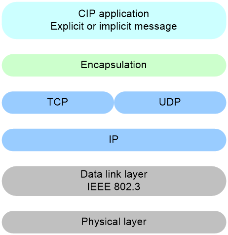
As shown in Table 1, EtherNet/IP uses the same physical layer, data link layer, and transport layer as standard Ethernet and adds an encapsulation layer above the transport layer. This encapsulation layer is used to package the CIP data coming from the application layer into a standard format.
Figure 1 EtherNet/IP network model
Communication mechanism
Messaging type
EtherNet/IP uses two types of messaging for communication between devices: explicit messaging and implicit messaging.
· Explicit messaging: Data is transmitted through TCP, suitable for scenarios that require accurate message delivery and are not time critical, such as configuring device information and uploading or downloading programs.
· Implicit messaging: Data is transmitted through UDP, suitable for transmission of time-critical data such as I/O data. A CIP connection must be established before implicit messaging. CIP connection is a CIP protocol service. After the connection is established, the two ends each hold a connection ID for subsequent information exchange.
Communication model
Explicit communication
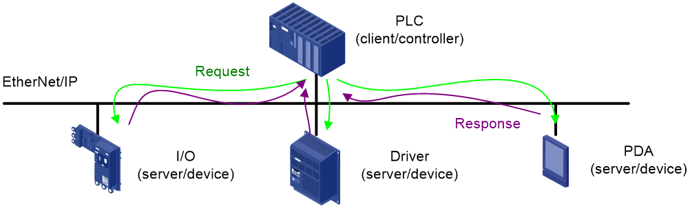
EtherNet/IP explicit communication uses a client/server model in which the industrial control device (controller) acts as the client, and peripheral I/O sensors, valves, industrial switches, or other measuring devices (devices) act as servers. The communication is initiated by the client, which sends a request to the servers. The servers respond accordingly after receiving the request.
Figure 2 EtherNet/IP explicit communication model
Implicit communication
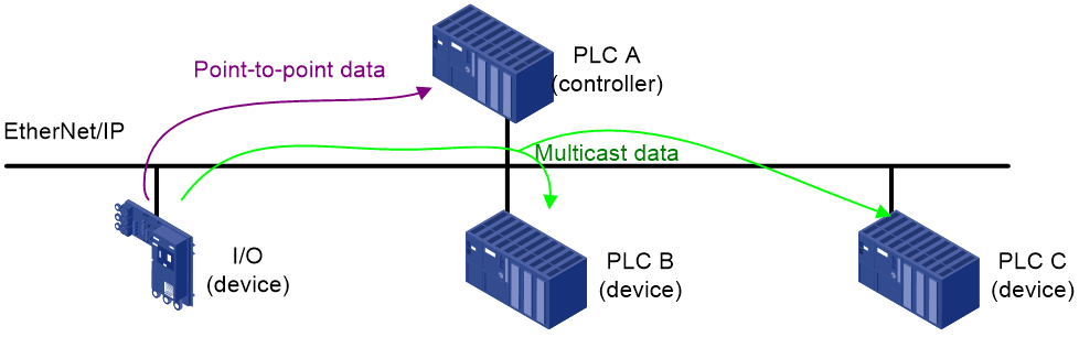
EtherNet/IP implicit communication uses a producer/consumer model. In this model, the devices act as data producers. They send their data onto the network all at once, allowing the controller to selectively read the data they require. This greatly enhances the communication efficiency of the entire EtherNet/IP network system.
Figure 3 EtherNet/IP implicit communication model
Message formats
Explicit communication message format
In explicit communication mode, EtherNet/IP encapsulates the CIP protocol data in the following format.
Figure 4 Explicit communication message format
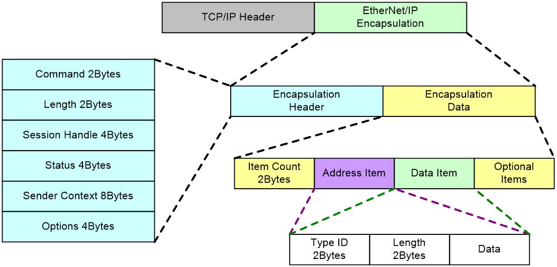
The EtherNet/IP explicit encapsulation package includes an encapsulation header and encapsulation data. The encapsulation header contains the following fields:
· Command: EtherNet/IP command that describes the function and purpose of the message, in 2 bytes.
· Length: Length of the data following the encapsulation header, in 2 bytes.
· Session Handle: TCP session handle, in 4 bytes.
· Status: Execution status of the EtherNet/IP command, in 4 bytes.
· Sender Context: Description of sender information, in 8 bytes.
· Options: Optional field, a maximum of 4 bytes.
The encapsulating data contains the following fields:
· Item Count: Total number of items in the packaged data.
· Address Item: Destination address information, including the address type, address length, and specific address.
· Data Item: CIP protocol data information, including the data type, data length, and specific data. The specific data includes the CIP command and request path.
Implicit communication message format
In implicit communication mode, EtherNet/IP encapsulates the CIP protocol data in the following format.
Figure 5 Implicit communication message format
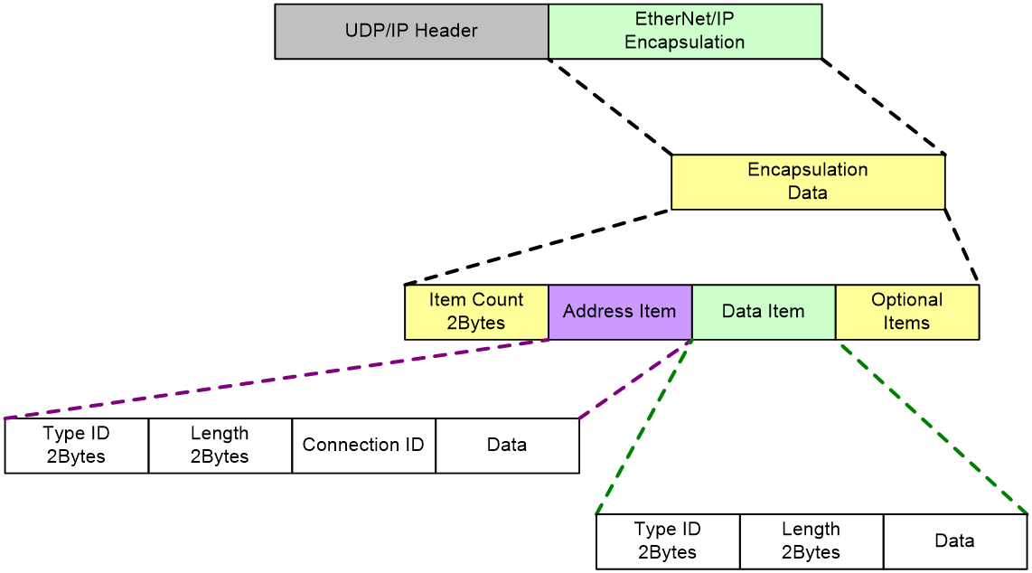
The EtherNet/IP explicit encapsulation package includes only the encapsulation data, which contains the following fields:
· Item Count: Total number of items in the packaged data.
· Address Item: Destination address information, including the address type, address length, CIP connection ID, and specific address. In implicit communication mode, EtherNet/IP determines the target by the connection ID.
· Data Item: CIP protocol data information, including the data type, data length, and specific data. The specific data includes the CIP command and request path.
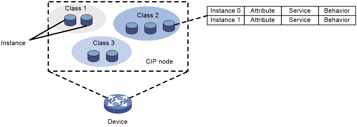
CIP object model
Each CIP node is a set of objects, and the targets of CIP communication are these specific objects. For EtherNet/IP communication, you can define specific components on a device as different objects.
Objects use a three-dimensional structure with classes, instances, and attributes. Multiple classes can exist on a CIP node, each class can have multiple instances, and each instance can have multiple attributes, as shown in Figure 6.
Figure 6 CIP object model diagram
Restrictions: Software version compatibility with EtherNet/IP
EtherNet/IP is supported only in F6355P05 and later.
Restrictions and guidelines
H3C industrial switches can act only as devices in EtherNet/IP communication. The term "device" in this configuration procedure collectively refers to H3C industrial switches.
Enabling EtherNet/IP
About this task
After EtherNet/IP is enabled on a device, the device can establish a TCP or UDP connection with the controller and perform EtherNet/IP communication over this connection. The controller can read and write the data or status of the device over EtherNet/IP. The device uses port number 44818 for establishing TCP connections and port number 2222 for establishing UDP connections.
Arbitrarily changing the status of the device might pose serious security risks to the entire network when a misoperation or malicious attack is present in the network. In such scenarios, switch the EtherNet/IP operating mode on the device to read-only mode. This ensures that the controller can only read information from the device via EtherNet/IP.
Prerequisites
The device uses VLAN 1 as the EtherNet/IP management VLAN for communication with the controller. Before enabling EtherNet/IP, first assign an IP address to VLAN interface 1.
Restrictions and guidelines
The controller can differentiate data of ports in the total data sent by the lower-level device by the port ID displayed in the display ethernet-ip information command.
Currently, the controller can read and modify the information of 128 ports on a device simultaneously.
Some CIP commands require a specific transport layer connection for EtherNet/IP communication.
Table 1 CIP command codes and required transport layer connection
|
Command code |
Name |
Connection method |
|
0x0000 |
NOP |
TCP |
|
0x0004 |
ListServices |
TCP or UDP |
|
0x0063 |
ListIdentity |
TCP or UDP |
|
0x0064 |
ListInterfaces |
TCP or UDP |
|
0x0065 |
RegisterSession |
TCP |
|
0x0066 |
UnRegisterSession |
TCP |
|
0x006F |
SendRRData |
TCP |
|
0x0070 |
SendUnitData |
TCP |
|
0x0072 |
IndicateStatus |
TCP |
|
0x0073 |
Cancel |
TCP |
Procedure
1. Enter system view.
system-view
2. Enable EtherNet/IP.
ethernet-ip enable
By default, EtherNet/IP is disabled.
3. (Optional) Set the EtherNet/IP operating mode to read-only.
ethernet-ip working-mode read-only
By default, the EtherNet/IP operating mode is read/write. In read/write mode, the device allows read/write operations from the controller over EtherNet/IP.
Display and maintenance commands for EtherNet/IP
Execute display commands in any view.
|
Task |
Command |
|
Display information required for reading port information via EtherNet/IP. |
display ethernet-ip information interface { interface-type interface-number | interface-name } |
Appendix A H3C device-specific object specifications
"instance=0" indicates a class attribute, which is shared by all objects within the same class. "instance>0" indicates an instance attribute, which is unique to an object instance.
Identity object (Class ID: 0x01)
Service codes
|
Service code |
Need in implementation |
Service name |
Description |
|
|
instance=0 |
instance>0 |
|||
|
0x0E |
Conditional (√) |
Conditional (√) |
Get_Attribute_Single |
Reads the specified attribute. |
|
0x05 |
Optional (x) |
Required (√) |
Reset |
Invokes the reset service for the device. |
|
0x01 |
Optional (√) |
Conditional (√) |
Get_Attributes_All |
Reads multiple attributes of the object. |
Class attributes (instance=0)
|
Class attribute |
Need in implementation |
Access rule |
Attribute name |
Data type |
Description |
|
0x01 |
√ |
Get |
Revision |
USHORT |
Object revision. |
|
0x02 |
√ |
Get |
Number of instances |
USHORT |
Number of object instances currently created in this class level of the device. |
|
0x06 |
√ |
Get |
Number of max attributes |
USHORT |
Maximum number of attributes in the current class. |
|
0x07 |
√ |
Get |
Number of max instance attributes |
USHORT |
Maximum number of attributes in the current instance. |
Instance attributes (instance>0)
|
Instance attribute |
Need in implementation |
Access rule |
Name |
Data type |
Description |
|
0x01 |
√ |
Get |
Vendor ID |
UINT |
Vendor ID. |
|
0x02 |
√ |
Get |
Device type |
UINT |
Device type. |
|
0x03 |
√ |
Get |
Product code |
UINT |
Product code: · 2465: H3C IE4320-28S · 2463: H3C IE4320-28P · 2464: H3C IE4320-28S-HPWR · 2479: H3C IE4320-52S · 2478: H3C IE4320-52P · 2487: H3C IE4320-28S-PS1 · 2552: H3C IE4320-12P-UPWR · 2551: H3C IE4320-28F · 2579: H3C IE4320-6P · 2576: H3C IE4320-12P · 2578: H3C IE4320-20P · 2577: H3C IE4320-6P-AC · 2604: H3C IE4320-12P-PWRM · 3470: H3C IE4320-28P-K · 3469: H3C IE4320-28P-S · 1749: H3C IE4300-28P-M · 1974: H3C IE4300-12P-PWR-M · 2225: H3C IE4300-12P-AC · 2226: H3C IE4300-12P-PWR · 25506: H3C Simware32/H3C Simware64 |
|
0x04 |
√ |
Get |
Revision |
STRUCT |
Device revision, including major and minor revisions, displayed in the major.minor format. |
|
Major revision |
USINT |
Major revision range: 0x 01 to 0x 7F. |
|||
|
Minor revision |
USINT |
Minor revision range: 0x01 to 0xFF. |
|||
|
0x05 |
√ |
Get |
Status |
WORD |
Device status. |
|
0x06 |
√ |
Get |
Serial number |
UDINT |
Serial number. |
|
0x07 |
√ |
Get |
Product name |
STRING |
Product name. |
Message router object (Class ID: 0x02)
The message router object strips the header of messages received from the Unconnected Message Manager (UCMM) or Transport, and parses the data. Then, it routes the service to the target class or attribute.
Service codes
|
Service code |
Need in implementation |
Service name |
Description |
|
|
Class attribute |
Instance attribute |
|||
|
0x0E |
Required (√) |
Required (√) |
Get_Attribute_Single |
Reads the specified attribute. |
|
0x01 |
Conditional (√) |
Conditional(√) |
Get_Attribute_All |
Reads the value of multiple attributes of the object. |
Class attributes (instance=0)
|
Class attribute |
Need in implementation |
Access rule |
Name |
Data type |
Description |
|
0x01 |
√ |
Get |
Revision |
UINT |
Object revision |
|
0x02 |
√ |
Get |
Max instance |
UINT |
Maximum instance number of an object currently created in this class level of the device. |
|
0x03 |
√ |
Get |
Number of instances |
UINT |
Number of object instances currently created at this class level of the device. |
Instance attributes (instance>0)
No instance attributes are currently available for the message router object.
Assembly object (Class ID: 0x04)
The assembly object binds attributes of multiple objects. It defines the parameters for I/O data exchange.
Service codes
|
Service code |
Need in implementation |
Service name |
Description |
|||
|
Static assembly |
Dynamic assembly (unsupported currently) |
|||||
|
|
Class attribute |
Instance attribute |
Class attribute |
Instance attribute |
|
|
|
0x0E |
Conditional (√) |
Required (√) |
Required (√) |
Required (√) |
Get_Attribute_Single |
Reads the specified attribute. |
|
0x08 |
N/A |
N/A |
Required |
N/A |
Create |
|
|
0x10 |
N/A |
Optional (√) |
N/A |
Conditional (√) |
Set_Attribute_Single |
Sets the specified attribute. |
|
0x09 |
N/A |
N/A |
Conditional |
Required |
Delete |
Deletes the assembly object and releases the resources. |
Class attributes (instance=0)
|
Class attribute |
Need in implementation |
Access rule |
Name |
Data type |
Description |
|
0x01 |
√ |
Get |
Revision |
UINT |
Object revision |
|
0x02 |
√ |
Get |
Max instance |
UINT |
Maximum instance number of an object currently created in this class level of the device. |
|
0x03 |
√ |
Get |
Number of instances |
UINT |
Number of object instances currently created at this class level of the device. |
Instance attributes (instance>0)
|
Instance attribute |
Need in implementation |
Access rule |
Name |
Data type |
Description |
|
0x03 |
Required (√) |
Get/Set |
Data |
ARRAY of BYTE |
I/O connection data. |
Connection manager object (Class ID: 0x06)
The connection manager object is responsible for establishment and termination of Common Industrial Protocol (CIP) connections.
Service codes
|
Service code |
Need in implementation |
Service name |
Description |
|
|
Class attribute |
Instance attribute |
|||
|
0x01 |
Optional (√) |
Optional (√) |
Get_Attributes_All |
Reads multiple attributes of the object. |
|
0x0E |
Conditional (√) |
Conditional (√) |
Get_Attribute_Single |
Reads the specified attribute. |
|
0x4E |
N/A |
Conditional (√) |
Forward_Close |
Closes a CIP connection. |
|
0x54 |
N/A |
Conditional (√) |
Forward_Open |
Opens a CIP connection. |
|
0x5A |
N/A |
Conditional (√) |
Get_Connection_Owner |
Determines the owner of a redundant connection. |
Class attributes (instance=0)
|
Class Attribute |
Need in implementation |
Access rule |
Name |
Data type |
Description |
|
0x01 |
√ |
Get |
Revision |
UINT |
Object revision |
|
0x02 |
√ |
Get |
Max instance |
UINT |
Maximum instance number of an object currently created in this class level of the device. |
|
0x03 |
√ |
Get |
Number of instances |
UINT |
Number of object instances currently created at this class level of the device. |
Instance attributes (instance>0)
No instance attributes are available currently for the connection manager object.
TCP/IP interface object (Class Code: 0xF5)
The TCP/IP interface object provides the mechanism to configure TCP/IP network interfaces on a device.
Service codes
|
Service code |
Need in implementation |
Service name |
Description |
|
|
Class attribute |
Instance attribute |
|||
|
0x01 |
Optional (√) |
Optional (√) |
Get_Attributes_All |
Reads multiple attributes of the object. |
|
0x0E |
Conditional (√) |
Required (√) |
Get_Attribute_Single |
Reads the specified attribute. |
|
0x10 |
N/A |
Required (√) |
Set_Attribute_Single |
Sets the specified attribute. |
Class attributes (instance=0)
|
Class Attribute |
Need in implementation |
Access rule |
Attribute name |
Data type |
Description |
|
0x01 |
√ |
Get |
Revision |
UINT |
Object revision |
|
0x02 |
√ |
Get |
Max instance |
UINT |
Maximum instance number of an object currently created in this class level of the device. |
|
0x03 |
√ |
Get |
Number of instances |
UINT |
Number of object instances currently created at this class level of the device. |
Instance attributes (instance>0)
|
Class attribute |
Need in implementation |
Access rule |
Attribute name |
Data type |
Description |
Remarks |
|
0x01 |
√ |
Get |
Status |
DWORD |
IP configuration status |
· 0—Not configured. · 1—Valid configuration obtained from Bootstrap Protocol (BOOTP), Dynamic Host Configuration Protocol (DHCP), or non-volatile storage. · 2—Configured by hardware. |
|
0x02 |
√ |
Get |
Configuration capability |
DWORD |
Configuration capability supported by the device |
· 0—BOOTP client · 1—DNS client · 2—DHCP client · 3—DHCP-DNS update · 4—Configuration settable · 5 to 31—Reserved |
|
0x03 |
√ |
Get/Set |
Configuration control |
DWORD |
Interface IP mode |
|
|
0x04 |
√ |
Get |
Physical link object |
STRUCT of: |
Path of the physical link object |
The obtained attribute is a structure composed of the following members. |
|
Path size |
UINT |
Path size |
|
|||
|
Path |
EPATH |
Specific path information |
|
|||
|
0x05 |
√ |
Get/Set |
Interface configuration |
STRUCT of: |
TCP/IP network configuration information of the device |
The obtained attribute is a structure composed of the following members. |
|
IP address |
UDINT |
IP address of the device |
|
|||
|
Network mask |
UDINT |
Subnet mask of the device |
|
|||
|
Gateway address |
UDINT |
Gateway of the device |
|
|||
|
Name server |
UDINT |
Primary name server |
|
|||
|
Name server 2 |
UDINT |
Secondary name server |
|
|||
|
Domain name |
STRING |
Default domain name |
|
|||
|
0x06 |
√ |
Get/Set |
Host name |
STRING |
Device name |
|
|
0x08 |
√ |
Get Set is conditional |
TTL value |
USINT |
TTL value of EtherNet/IP multicast packets |
|
|
0x09 |
√ |
Get Set is conditional |
Mcast config |
STRUCT of: |
Multicast IP address configuration information |
The obtained attribute is a structure composed of the following members. |
|
Alloc control |
USINT |
Multicast address allocation status |
|
|||
|
Reserved |
USINT |
|
|
|||
|
Num Mcast |
UINT |
Number of allocable multicast addresses |
|
Ethernet link object (Class Code: 0xF6)
An Ethernet link maintains link-specific counters and status information for an Ethernet interface.
Service codes
|
Service code |
Need in implementation |
Service name |
Description |
|
|
Class attribute |
Instance attribute |
|||
|
0x01 |
Optional (√) |
Optional (√) |
Get_Attributes_All |
Reads multiple attributes of the object. |
|
0x0E |
Conditional (√) |
Required (√) |
Get_Attribute_Single |
Reads the specified attribute. |
Class attributes (instance=0)
|
Class Attribute |
Need in implementation |
Access rule |
Attribute name |
Data type |
Description |
|
0x01 |
√ |
Get |
Revision |
UINT |
Object revision |
|
0x02 |
√ |
Get |
Max instance |
UINT |
Maximum instance number of an object currently created in this class level of the device. |
|
0x03 |
√ |
Get |
Number of Instances |
UINT |
Number of object instances currently created at this class level of the device. |
Instance attributes (instance>0)
|
Class attribute |
Need in implementation |
Access rule |
Attribute name |
Data type |
Description |
Remarks |
|
0x01 |
√ |
Get |
Interface speed |
DWORD |
Interface speed |
10 Mbps 100 Mbps 1 G |
|
0x02 |
√ |
Get |
Interface flags |
DWORD |
Interface flags |
|
|
0x03 |
√ |
Get |
Physical address |
ARRAY of 6 USINTS |
MAC address |
|
|
0x0A |
√ |
Get |
Interface label |
SHORT_ STRING |
Interface name |
|
Appendix B H3C device-specific CIP data in explicit messaging
To retrieve or set the status of an H3C device, the industrial control device (controller) must first send a request carrying the set attribute single command to that device. Subsequently, the controller sends a request carrying the get attribute single command to formally request the data.
|
Service |
Parameters |
|
set attribute single |
Service: 16 Class: 4 Instance: 104 Attribute: 3 |
|
Get attribute single |
Service: 14 Class: 4 Instance: 103 Attribute: 3 |
Requesting port and alarm data
To retrieve port and alarm data of an H3C device, the controller needs to send a request that carries the set attribute single command to that device. This request populates the first two bytes of the data portion with 0x0000, and the succeeding bytes as follows:
|
Third byte |
Fourth byte |
|||||||
|
00 |
01 |
02 |
03 |
04 |
05 |
… |
n |
|
|
Port status and alarms (00) |
|
|
|
|
|
|
|
|
After receiving the request packet with the get attribute single command, the H3C device replies to the controller with a response packet. The value starting at position 05 in the response message is as follows:
Port information
|
Input byte offset num |
Status item |
|
Position in the data portion of the packet (byte) |
Each byte represents the status of four ports. The port status occupies 32 bytes. The succeeding bytes are alarm information. |
|
0 |
Status of ports 1 to 4 |
|
1 |
Status of ports 5 to 8 |
|
2 |
Status of ports 9 to 12 |
|
3 |
Status of ports 13 to 16 |
|
4 |
Status of ports 17 to 20 |
|
5 |
Status of ports 21 to 24 |
|
6 |
Status of ports 25 to 28 |
|
7 |
Status of ports 29 to 32 |
|
8 |
Status of ports 33 to 36 |
|
9 |
Status of ports 37 to 40 |
|
10 |
Status of ports 41 to 44 |
|
11 |
Status of ports 45 to 48 |
|
12 |
Status of ports 49 to 52 |
|
13 |
Status of ports 53 to 56 |
|
14 |
Status of ports 57 to 60 |
|
15 |
Status of ports 61 to 64 |
|
16 |
Status of ports 65 to 68 |
|
17 |
Status of ports 69 to 72 |
|
18 |
Status of ports 73 to 76 |
|
19 |
Status of ports 77 to 80 |
|
20 |
Status of ports 81 to 84 |
|
21 |
Status of ports 85 to 88 |
|
22 |
Status of ports 89 to 92 |
|
23 |
Status of ports 93 to 96 |
|
24 |
Status of ports 97 to 100 |
|
25 |
Status of ports 101 to 104 |
|
26 |
Status of ports 105 to 108 |
|
27 |
Status of ports 109 to 112 |
|
28 |
Status of ports 113 to 116 |
|
29 |
Status of ports 117 to 120 |
|
30 |
Status of ports 121 to 124 |
|
31 |
Status of ports 125 to 128 |
|
The status of each port is represented by 2 bits. The available port status in binary are: · 00: Disabled · 01: Up · 10: Down A port is considered enabled if it is in up or down state. |
|
Alarm information
|
Position in the data portion of the message (byte) |
Name |
Value |
Data length (bytes) |
|
32 |
Port 1 alarm status |
0x00: disable 0x01: normal 0x02: alarm |
1 |
|
33 |
Port 2 alarm status |
0x00: disable 0x01: normal 0x02: alarm |
1 |
|
34 |
Ports 3 to 128 alarm status Each port occupies 1 byte |
0x01: normal 0x02: alarm |
62 |
|
160 |
Temperature alarm status |
0x01: normal 0x02: alarm |
1 |
|
161 |
CPU alarm status |
0x01: normal 0x02: alarm |
1 |
|
162 |
Memory alarm status |
0x01: normal 0x02: alarm |
1 |
|
163 |
Power supply alarm status |
0x01: normal 0x02: Power supply 1 alarm 0x03: Power supply 2 alarm |
1 |
|
164 to 255 |
Reserved |
|
|
Requesting device status data
To retrieve status data of an H3C device, the controller sends a request that carries the set attribute single command to that device. This request populates the first two bytes of the data portion with 0x0000, and the succeeding bytes as follows:
|
Third byte |
Fourth byte |
Fifth byte |
|||||||||||||||
|
Data category (Table) |
Data category (node)/index |
Data subcategory (node)/subindex |
|||||||||||||||
|
00 |
01 |
02 |
03 |
04 |
05 |
06 |
… |
n(ff) |
00 |
01 |
... |
n |
|||||
|
01 (Device information) |
|
Vendor name |
Device type |
Vendor address |
Phone number |
Product name |
Additional information |
|
|
\ |
|||||||
|
02 (Port information) |
|
First port |
Second port |
Third port |
Fourth port |
Fifth port |
Sixth port |
|
Nth port |
\ |
|||||||
|
03 (RSTP information) |
Global info |
Ring network info on the first port |
Ring network info on the second port |
Ring network info on the third port |
Ring network info on the fourth port |
Ring network info on the fifth port |
Ring network info on the sixth port |
|
Ring network info on the Nth port |
\ |
|||||||
|
04 (ERPS ring network info) |
Global info |
First ERPS ring info |
Second ERPS ring info |
Third ERPS ring info |
Fourth ERPS ring info |
Fifth ERPS ring info |
Sixth ERPS ring info |
|
Nth ERPS ring info |
\ |
|||||||
|
05 (ERPS ring instance info) |
Global info |
First ERPS ring info |
Second ERPS ring info |
Third ERPS ring info |
Fourth ERPS ring info |
Fifth ERPS ring info |
Sixth ERPS ring info |
|
Nth ERPS ring info |
\ |
First instance info |
... |
Nth instance info |
||||
|
06 (RRPP domain info) |
Global info |
First RRPP domain info |
Second RRPP domain info |
Third RRPP domain info |
Fourth RRPP domain info |
Fifth RRPP domain info |
Sixth RRPP domain info |
|
Nth RRPP domain info |
\ |
|||||||
|
07 (RRPP ring network info) |
Global info |
First RRPP domain info |
Second RRPP domain info |
Third RRPP domain info |
Fourth RRPP domain info |
Fifth RRPP domain info |
Sixth RRPP domain info |
|
Nth RRPP domain info |
\ |
First RRPP ring information |
... |
Nth RRPP ring information |
||||
After receiving the request packet with the get attribute single command, the H3C device replies to the controller with a response packet. The value starting from position 05 in the response packet is as follows:
Device information (01)
|
Position in the data portion of the message (byte) |
Name |
Value |
Data length (bytes) |
|
00 |
Whether the request is successful or failed |
0x0000: Successful. 0xFFFF: Failed |
2 |
|
02 |
Serial number |
|
33 |
|
35 |
Boot ROM version |
|
64 |
|
99 |
Current running software version |
|
64 |
|
163 |
Device IP address |
192.168.0.1 (C0 A8 00 01)
|
4 |
|
167 |
MAC address of the MPU |
|
4 |
|
171 |
Device bridge MAC address |
|
6 |
|
177 |
Power supply 1 status information |
0x00: Power off 0x01: Power on |
1 |
|
178 |
Power supply 2 status information |
0x00: Power off 0x01: Power on |
1 |
|
179 |
CPU usage in percentage (long term) |
|
4 |
|
183 |
CPU usage in percentage (short term) |
|
4 |
|
187 |
Total memory (bytes) |
|
4 |
|
191 |
Free memory (bytes) |
|
4 |
|
195 |
Device uptime (minutes) |
|
8 |
|
203 to 255 |
Reserved |
|
|
Port information (02)
|
Position in the data portion of the message (byte) |
Name |
Value |
Data length (bytes) |
|
00 |
Whether the request is successful or failed |
0x0000: Successful. 0xFFFF: Failed |
2 |
|
02 |
Port name |
|
64 |
|
66 |
Port state |
· 0x00: Disabled · 0x01: Up · 0x02: Down |
1 |
|
67 |
Port speed |
|
1 |
|
68 |
Duplex mode |
· 0x01: Half · 0x02: Full · 0x03: Auto |
1 |
|
69 |
Flow control enabling status |
· 0x00: Off · 0x01: On |
1 |
|
70 |
Received packet count |
|
8 |
|
78 |
Received byte count |
|
8 |
|
86 |
Transmitted packet count |
|
8 |
|
94 |
Transmitted byte count |
|
8 |
|
102 |
Received unicast packet count |
|
8 |
|
110 |
Received multicast packet count |
|
8 |
|
118 |
Received broadcast packet count |
|
8 |
|
126 |
Transmitted unicast packet count |
|
8 |
|
134 |
Transmitted multicast packet count |
|
8 |
|
142 |
Transmitted broadcast packet count |
|
8 |
|
150 |
Received pause frame count |
|
8 |
|
158 |
Transmitted pause frame count |
|
8 |
|
166 |
Received CRC error packet count |
|
8 |
|
174 to 255 |
Reserved |
|
|
RSTP information (03)
RSTP global information
|
Position in the data portion of the message (byte) |
Name |
Value |
Data length (bytes) |
|
00 |
Whether the request is successful or failed |
0x0000: Successful. 0xFFFF: Failed |
2 |
|
02 |
RSTP global enabling status |
· 0—Disabled · 1—Enabled |
2 |
|
04 |
Root bridge ID |
8 byes |
8 |
|
12 |
Bridge ID |
8 byes |
8 |
|
20 |
Priority |
Value range: 0 to 61440 |
4 |
|
24 |
Hello time at which the root device sends BPDUs |
Value range: 1 to10 |
4 |
|
28 |
Max age of BPDUs |
Value range: 6 to 40 |
4 |
|
32 |
Forward delay |
Value range: 4 to 30 |
4 |
RSTP port information
|
Position in the data portion of the message (byte) |
Name |
Value |
Data length (bytes) |
|
00 |
Whether the request is successful or failed |
0x0000: Successful. 0xFFFF: Failed |
2 |
|
02 |
RSTP port enabling status |
· 0—Disabled · 1—Enabled |
2 |
|
04 |
Port priority |
Value range: 0 to 240 |
4 |
|
08 |
Path cost |
Value range: 0 to 200000000 |
4 |
|
12 |
Port role |
· 0—Disabled port · 1—Alternate port · 2—Backup port · 3—Root port · 4—Designated port · 5—Master port |
4 |
|
16 |
Port state |
· 1—Discarding · 2—Learning · 3—Forwarding |
4 |
ERPS ring network information (04)
ERPS ring network global information
|
Position in the data portion of the message (byte) |
Name |
Value |
Data length (bytes) |
|
00 |
Whether the request is successful or failed |
0x0000: Successful. 0xFFFF: Failed |
2 |
|
02 |
ERPS global enabling status |
0: disable 1: enable |
2 |
ERPS ring information
|
Position in the data portion of the message (byte) |
Name |
Value |
Data length (bytes) |
|
00 |
Whether the request is successful or failed |
0x0000: Successful. 0xFFFF: Failed |
2 |
|
02 |
ERPS ring ID |
Value range: 1 to 8 |
2 |
|
04 |
ERPS ring member port 0 |
Port name |
64 |
|
68 |
RPS ring member port 1 |
Port name |
64 |
|
132 |
ERPS ring instance list |
|
64 |
|
197-255
|
Reserved
|
|
|
ERPS instance information (05)
ERPS ring network global information
|
Position in the data portion of the message (byte) |
Name |
Value |
Data length (bytes) |
|
00 |
Whether the request is successful or failed |
0x0000: Successful. 0xFFFF: Failed |
2 |
|
02 |
ERPS global enabling status |
0: disable 1: enable |
2 |
ERPS instance information
|
Position in the data portion of the message (byte) |
Name |
Value |
Length (bytes) |
|
00 |
Whether the request is successful or failed |
0x0000: Successful. 0xFFFF: Failed |
2 |
|
02 |
ERPS ring ID |
Value range: 1 to 8 |
2 |
|
04 |
ERPS instance ID |
Value range: 1 to 64 |
2 |
|
06 |
ERPS instance enabling status |
0: The instance is not enabled. 1: The instance is enabled. |
1 |
|
07 |
Control VLAN of the ERPS instance |
Value range: 2 to 4094 |
2 |
|
09 |
Node role |
String. · Owner: Owner node. · Neighbor: Neighbor · Interconnection: Interconnection node · Normal: Normal node |
32 |
|
41 |
Node state |
String. · Idle: Stable state when all non-RPL links are available · Protection: State when a non-RPL link is faulty. In this state, the RPL link is unblocked to forward traffic. All nodes enter the protection state after a node enters the protection state. · MS: State when traffic paths are manually switched. · FS: State when traffic paths are forcibly switched. · Pending: Transitional state between two states. · -: ERPS is disabled globally or for the instance. |
32 |
|
73 |
ERPS ring member port 0 |
Port name. |
64 |
|
137 |
Role of ERPS ring member port 0 |
String. · RPL · Non-RPL |
8 |
|
145 |
State of ERPS ring member port 0 |
String. · Blocked · Up · Down |
8 |
|
153 |
ERPS ring member port 1 |
Port name. |
64 |
|
217 |
Role of ERPS ring member port 1 |
Port role. String. · RPL · Non-RPL |
8 |
|
225 |
State of ERPS ring member port 1 |
Port state. String. · Blocked · Up · Down |
8 |
|
233-255 |
Reserved |
|
|
RRPP domain information (06)
RRPP ring network global information
|
Data portion position (byte) |
Name |
Value |
Data length (bytes) |
|
00 |
Whether the request is successful or failed |
0x0000: Successful. 0xFFFF: Failed |
2 |
|
02 |
RRPP global enabling status |
0: disable 1: enable |
2 |
RRPP domain information
|
Data portion position (byte) |
Name |
Value |
Data length (bytes) |
|
Position in the data portion of the message (byte) |
Data name |
Data example |
Data length (bytes) |
|
00 |
Whether the request is successful or failed |
0x0000: Successful. 0xFFFF: Failed |
2 |
|
02 |
RRPP domain ID |
Value range: 1 to 8 |
2 |
|
04 |
Control VLAN of the RRPP domain |
Value range: 2 to 4094 |
2 |
|
06 |
Ring list of the RRPP domain |
|
128 |
RRPP ring information (07)
RRPP ring network global information
|
Position in the data portion of the message (byte) |
Name |
Value |
Data length (bytes) |
|
00 |
Whether the request is successful or failed |
0x0000: Successful. 0xFFFF: Failed |
2 |
|
02 |
RRPP global enabling status |
0: Disabled 1: Enabled |
2 |
RRPP ring information
|
Position in the data portion of the message (byte) |
Name |
Value |
Data length (bytes) |
|
00 |
Whether the request is successful or failed |
0x0000: Successful. 0xFFFF: Failed |
2 |
|
02 |
RRPP domain ID |
Value range: 1 to 8 |
2 |
|
04 |
RRPP ring ID |
Value range: 1 to 64 |
2 |
|
06 |
Ring level |
· 0—Primary ring · 1—subring |
1 |
|
07 |
RRPP ring enabling status |
· 0—RRPP ring is not enabled. · 1— RRPP ring is enabled. |
1 |
|
08 |
Node role |
· 0—Transit node · 1—Master node · 2—Edge node · 3—Assistant edge node |
1 |
|
09 |
RRPP ring state |
· 0—Completed · 1—Failed · 2—LinkUp · 3—LinkDown · 4—PreForward · 5—LinkUpNotify · 6—LinkDnNotify · 7—PreForwardNotify · 8—Unknown |
1 |
|
10 |
RRPP ring primary port |
Value range: 1 to 128 |
4 |
|
14 |
RRPP ring primary port status |
Port status: · 0—down. · 1—up. · 2—blocked. |
1 |
|
15 |
RRPP ring secondary port |
Value range: 1 to 128 |
4 |
|
19 |
RRPP ring secondary port status |
Port status: · 0—down. · 1—up. · 2—blocked. |
1 |
|
20 |
RRPP ring edge port |
Value range: 1 to 128 |
4 |
|
24 |
RRPP ring edge port status |
Port status: · 0—down. · 1—up. · 2—blocked. |
1 |
Setting the device status
To set the port status of an H3C device, the controller sends a request that carries the set attribute single command to the device. This request populates the first two bytes of the data portion with 0x0100, and the succeeding bytes as follows:
|
Input byte offset num |
Status item |
|
Position in the data portion of the message (byte) |
|
|
3 |
Status for ports 1 to 4 |
|
4 |
Status of ports 5 to 8 |
|
5 |
Status of ports 9 to 12 |
|
6 |
Status of ports 13 to 16 |
|
7 |
Status of ports 17 to 20 |
|
8 |
Status of ports 21 to 24 |
|
9 |
Status of ports 25 to 28 |
|
10 |
Status of ports 29 to 32 |
|
11 |
Status of ports 33 to 36 |
|
12 |
Status of ports 37 to 40 |
|
13 |
Status of ports 41 to 44 |
|
14 |
Status of ports 45 to 48 |
|
15 |
Status of ports 49 to 52 |
|
16 |
Status of ports 53 to 56 |
|
17 |
Status of ports 57 to 60 |
|
18 |
Status of ports 61 to 64 |
|
19 |
Status of ports 65 to 68 |
|
20 |
Status of ports 69 to 72 |
|
21 |
Status of ports 73 to 76 |
|
22 |
Status of ports 77 to 80 |
|
23 |
Status of ports 81 to 84 |
|
24 |
Status of ports 85 to 88 |
|
25 |
Status of ports 89 to 92 |
|
26 |
Status of ports 93 to 96 |
|
27 |
Status of ports 97 to 100 |
|
28 |
Status of ports 101 to 104 |
|
29 |
Status of ports 105 to 108 |
|
30 |
Status of ports 109 to 112 |
|
31 |
Status of ports 113 to 116 |
|
32 |
Status of ports 117 to 120 |
|
33 |
Status of ports 121 to 124 |
|
34 |
Status of ports 125 to 128 |
|
The port status of each port is represented by 2 bits. The binary value 01 represents to enable the port, 10 represents to disable the port, and 00 and 11 represent to keep the port status unchanged. |
|
Appendix C H3C device-specific CIP data in implicit messaging
A CIP connection must be established between an H3C device and the controller to initiate implicit communication. The connection parameters need to be configured as follows:
|
Transport type |
Class ID |
Instance ID |
Connection point |
Data size |
|
Input |
4 |
3 |
101 0x65 |
200 bytes |
|
Output |
102 0x66 |
40 bytes |
The output message in implicit communication contains the desired status for each port. The Input message contains the current status and alarm information of each port.
Output message
The output message describes the desired status for each port.
|
Input byte offset num |
Status item |
|
Position in the data portion of the message (byte) |
Transaction number. The device will process the output message (2 bytes) only when the transaction number is updated. If the transaction number is not updated, the succeeding message portion will not be read and analyzed. |
|
|
Run idle buf, which is set to 0 (4bytes). The output length set in the connection point starts counting from below. The data location is also counted from below. |
|
0 |
Status of ports 1 to 4 |
|
1 |
Status of ports 5 to 8 |
|
2 |
Status of ports 9 to 12 |
|
3 |
Status of ports 13 to 16 |
|
4 |
Status of ports 17 to 20 |
|
5 |
Status of ports 21 to 24 |
|
6 |
Status of ports 25 to 28 |
|
7 |
Status of ports 29 to 32 |
|
8 |
Status of ports 33 to 36 |
|
9 |
Status of ports 37 to 40 |
|
10 |
Status of ports 41 to 44 |
|
11 |
Status of ports 45 to 48 |
|
12 |
Status of ports 49 to 52 |
|
13 |
Status of ports 53 to 56 |
|
14 |
Status of ports 57 to 60 |
|
15 |
Status of ports 61 to 64 |
|
16 |
Status of ports 65 to 68 |
|
17 |
Status of ports 69 to 72 |
|
18 |
Status of ports 73 to 76 |
|
19 |
Status of ports 77 to 80 |
|
20 |
Status of ports 81 to 84 |
|
21 |
Status of ports 85 to 88 |
|
22 |
Status of ports 89 to 92 |
|
23 |
Status of ports 93 to 96 |
|
24 |
Status of ports 97 to 100 |
|
25 |
Status of ports 101 to 104 |
|
26 |
Status of ports 105 to 108 |
|
27 |
Status of ports 109 to 112 |
|
28 |
Status of ports 113 to 116 |
|
29 |
Status of ports 117 to 120 |
|
30 |
Status of ports 121 to 124 |
|
31 |
Status of ports 125 to 128 |
|
32 to 39 |
Reserved |
|
The first 32 bytes of the message indicate the desired status for the ports, with 2 bits for each port. 01 represents to enable the port, 10 represents to disable the port, 00 and 11 represent to keep the port status unchanged. The last eight bytes are reserved. |
|
Input message
The input message describes the current status of ports.
Port information in the input message
|
Input byte offset num |
Status item |
|
Position in the data portion of the message (byte) |
Transaction number. The device will process the output message (2 bytes) only when the transaction number is updated. If the transaction number is not updated, the succeeding message portion will not be read and analyzed. The output length set in the connection point starts counting from below. The data location is also counted from below. |
|
0 |
Status of ports 1 to 4 |
|
1 |
Status of ports 5 to 8 |
|
2 |
Status of ports 9 to 12 |
|
3 |
Status of ports 13 to 16 |
|
4 |
Status of ports 17 to 20 |
|
5 |
Status of ports 21 to 24 |
|
6 |
Status of ports 25 to 28 |
|
7 |
Status of ports 29 to 32 |
|
8 |
Status of ports 33 to 36 |
|
9 |
Status of ports 37 to 40 |
|
10 |
Status of ports 41 to 44 |
|
11 |
Status of ports 45 to 48 |
|
12 |
Status of ports 49 to 52 |
|
13 |
Status of ports 53 to 56 |
|
14 |
Status of ports 57 to 60 |
|
15 |
Status of ports 61 to 64 |
|
16 |
Status of ports 65 to 68 |
|
17 |
Status of ports 69 to 72 |
|
18 |
Status of ports 73 to 76 |
|
19 |
Status of ports 77 to 80 |
|
20 |
Status of ports 81 to 84 |
|
21 |
Status of ports 85 to 88 |
|
22 |
Status of ports 89 to 92 |
|
23 |
Status of ports 93 to 96 |
|
24 |
Status of ports 97 to 100 |
|
25 |
Status of ports 101 to 104 |
|
26 |
Status of ports 105 to 108 |
|
27 |
Status of ports 109 to 112 |
|
28 |
Status of ports 113 to 116 |
|
29 |
Status of ports 117 to 120 |
|
30 |
Status of ports 121 to 124 |
|
31 |
Status of ports 125 to 128 |
|
The status of each port is represented by 2 bits: · 00: Disabled · 01: Up · 10: Down A port is considered enabled if it is in up or down state. |
|
Alarm information in the input message
|
Position in the data portion of the message (byte) |
Name |
Value |
Data length (bytes) |
|
32 |
Port 1 alarm status |
0x00: Disabled 0x01: Normal 0x02: Alarm |
|
|
33 |
Port 2 alarm status |
0x00: Disabled 0x01: Normal 0x02: Alarm |
|
|
34 |
Ports 3 to 128 alarm status Each port occupies 1 byte |
0x01: Normal 0x02: Alarm |
|
|
160 |
Temperature alarm status |
0x01: Normal 0x02: Alarm |
|
|
161 |
CPU alarm status |
0x01: Normal 0x02: Alarm |
|
|
162 |
Memory alarm status |
0x01: Normal 0x02: Alarm |
|
|
163 |
Power supply alarm status |
0x01: Normal 0x02: Power supply 1 alarm 0x03: Power supply 2 alarm |
|
|
164 to 199 |
Reserved |
|
|
