- Table of Contents
- Related Documents
-
01-Text
Hybrid copper-fiber transceiver modules
H3C iOptic 3.0 transceiver modules
Immersive liquid-cooled transceiver modules
Safety and Regulatory Compliance Information
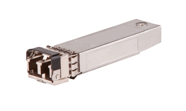
QSFP-DD optical transceiver modules (MPO interface)
QSFP-DD optical transceiver modules (LC interface)
QSFP56 optical transceiver modules (MPO interface)
QSFP56 optical transceiver modules (LC interface)
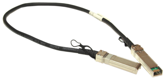
QSFP56 to QSFP56 copper cables
QSFP28 optical transceiver modules (MPO interface)
QSFP28 liquid-cooled transceiver modules (MPO interface)
QSFP28 optical transceiver modules (LC interface)
100-Gigabit CFP optical transceiver modules
40-Gigabit CFP optical transceiver modules
CFP2 optical transceiver modules (MPO interface)
CFP2 optical transceiver modules (LC interface)
CXP optical transceiver modules
QSFP+ optical transceiver modules (MPO interface)
QSFP+ optical transceiver modules (LC interface)
SFP28 optical transceiver modules
SFP+ optical transceiver modules (LC interface)
SFP+ optical transceiver modules (SC interface)
10G EPON OLT SFP+ optical transceiver modules (SC interface)
SFP+ copper transceiver modules
XFP optical transceiver modules (LC interface)
10G EPON OLT XFP optical transceiver modules (SC interface)
2.5-Gigabit SFP optical transceiver modules
SFP GPON ONU optical transceiver modules (SC interface)
SFP GPON OLT optical transceiver modules (SC interface)
Gigabit SFP optical transceiver modules
622-Megabit SFP optical transceiver modules
100-Megabit SFP optical transceiver modules
Gigabit BIDI optical transceiver modules
100-Megabit BIDI optical transceiver modules
BIDI GEPON OLT optical transceiver modules (SC interface)
Gigabit CWDM optical transceiver modules (LC interface)
Gigabit SFP copper transceiver modules
Hybrid copper-fiber transceiver modules
SFP+ hybrid copper-fiber transceiver modules (PELC interface)
SFP hybrid copper-fiber transceiver modules (PELC interface)
Hybrid copper-fiber cable jumpers
Hybrid copper-fiber cable pigtail
iOptic 3.0 dedicated transceiver modules
SFP28 iOptic 3.0 dedicated transceiver modules (LC interface)
SFP+ iOptic 3.0 dedicated transceiver modules (LC interface)
2.5G SFP iOptic 3.0 dedicated transceiver modules (LC interface)
SFP iOptic 3.0 dedicated transceiver modules (LC interface)
Overview
Table 1 describes transceiver modules and network cables available for H3C devices. All these transceiver modules and network cables are hot swappable.
Table 1 Transceiver modules and network cables available for H3C devices
|
Interface connector |
Data rate |
||
|
QSFP-DD module (transceiver) |
QSFP-DD optical transceiver module |
Dual LC |
400 Gbps |
|
QSFP-DD optical transceiver module |
MPO |
||
|
QSFP-DD copper cable |
N/A |
||
|
QSFP56 module (transceiver) |
QSFP56 optical transceiver module |
MPO |
200 Gbps |
|
QSFP56 optical transceiver module |
LC |
||
|
QSFP56 copper cable |
N/A |
||
|
QSFP56 to QSFP56 copper cable |
|||
|
QSFP56 fiber cable |
|||
|
QSFP28 module (transceiver) |
QSFP28 optical transceiver module |
MPO/dual LC |
100/50 Gbps |
|
QSPF28 BIDI optical transceiver module |
Dual LC |
100 Gbps |
|
|
QSFP28 copper cable |
N/A |
||
|
QSFP28 fiber cable |
|||
|
CFP module (transceiver) |
100-Gigabit CFP optical transceiver module |
Dual LC |
100 Gbps |
|
40-Gigabit CFP optical transceiver module |
|||
|
CFP2 module (transceiver) |
CFP2 optical transceiver module |
MPO/dual LC |
100 Gbps |
|
CXP module (transceiver) |
100-Gigabit CXP optical transceiver module |
MPO |
100 Gbps |
|
100-Gigabit CXP fiber cable |
N/A |
||
|
QSFP+ module (transceiver) |
QSFP+ optical transceiver module |
MPO/dual LC |
40 Gbps |
|
QSPF+ BIDI optical transceiver module |
Dual LC |
||
|
QSFP+ copper cable (for interconnecting QSFP+ ports) |
N/A |
||
|
QSFP+ to SFP+ copper cable (for connecting one 40-Gigabit QSFP+ port to four 10-Gigabit SFP+ ports) |
N/A |
||
|
QSFP+ fiber cable |
|||
|
SFP28 module (transceiver) |
SFP28 optical transceiver module |
Dual LC |
25 Gbps |
|
SFP28 copper cable |
N/A |
||
|
SFP28 fiber cable |
|||
|
SFP+ module (transceiver) |
SFP+ optical transceiver module |
Dual LC/SC |
10 Gbps |
|
SFP+ BIDI optical transceiver module |
Dual LC |
||
|
SFP+ copper cable (for interconnecting devices) |
N/A |
||
|
SFP+ fiber cable |
|||
|
PSFP+ module |
PSFP+ optical transceiver module |
PELC |
10/5/2.5/1 Gbps |
|
10-Gigabit small form-factor pluggable (XFP) module (transceiver) |
XFP optical transceiver module |
Dual LC |
See Table 63. |
|
10G EPON OLT optical transceiver module |
SC |
See Table 65. |
|
|
10-Gigabit CX4 cable (for interconnecting devices) |
N/A |
12 Gbps |
|
|
PSFP module |
PSFP optical transceiver module |
PELC |
1250 Mbps |
|
Small form-factor pluggable (SFP) module (transceiver) |
2.5-Gigabit SFP optical transceiver module |
Dual LC |
2.5 Gbps |
|
Gigabit SFP optical transceiver module |
1250 Mbps |
||
|
622-Megabit SFP optical transceiver module |
622 Mbps |
||
|
100-Megabit SFP optical transceiver module |
155 Mbps |
||
|
Gigabit bi-direction (BIDI) optical transceiver module |
Dual LC |
1250 Mbps |
|
|
100-Megabit bi-direction (BIDI) optical transceiver module |
155 Mbps |
||
|
BIDI GEPON OLT optical transceiver module |
SC |
1250 Mbps |
|
|
Gigabit GPON ONU optical transceiver module |
SC |
1250 Mbps |
|
|
Gigabit coarse wavelength division multiplexing (CWDM) optical transceiver module |
Dual LC |
1250 Mbps |
|
|
Gigabit SFP copper transceiver module |
RJ-45 |
1250 Mbps |
|
|
Gigabit SFP copper cable (for interconnecting devices) |
N/A |
1250 Mbps |
|
|
|
IMPORTANT: The commercial outer casing temperature range is 0°C to 70°C (32°F to 158°F) and industrial outer casing temperature range is –40°C to +85°C (–40°F to +185°F) for H3C transceiver modules. The commercial temperature range is applicable to all transceiver modules except for transceiver modules marked with * and transceiver modules with special temperature requirements specified in this document. An abnormal outer casing temperature might reduce the performance, signal transmission quality, and link status of the transceiver module, and even damage the transceiver module. |
|
|
NOTE: · The available transceiver modules and network cables vary by device models and are subject to change over time. For the most up-to-date list of transceiver modules and network cables, contact your H3C sales representative or technical support engineer. · For information about the transceiver modules and network cables available for each device model, see the installation guides. |
Optical transceiver modules
Optical modules transmit signals over optical fibers. Optical transmission features low loss and is fit for long distance transmission.
H3C devices support optical module models of different specifications. You can choose optical modules as needed for data transmission over optical fibers.
The optical modules include optical transmitters, optical receivers, transceivers, and transponders.
H3C devices support transceivers. Transceivers are mainly used for optical-to-electrical and electrical-to-optical conversions and provide the following functions: optical power control, modulation transmission, signal probe, IV conversion, and limiting amplifier and decision regeneration. In addition, transceivers provide some other functions, such as counterfeit-prevention query and TX-disable. Common form factors for transceiver modules include QSFP-DD, QSFP56, QSFP28, CFP, CFP2, CXP, QSFP+, SFP28, SFP+, and SFP.
Data rate
Transmission distance
The transmission distance of optical transceiver modules is divided into short and long-range types. A distance of 2 km (1.24 miles) and below is generally considered as short-range type. 10 km (6.21 miles) is considered as long-range type.
Transmission distances provided by optical transceiver modules are mainly limited by certain loss and dispersion suffered during the transmission of optical signals over optical fibers.
· Loss is the optical energy loss due to the absorption, dispersion and leakage over the media when light travels through optical fibers. This loss increases in direct ratio to transmission distance.
· Dispersion happens mainly because electromagnetic waves of different wavelengths travel at different rates over the same medium, causing different wave components of optical signals to reach the receiving end early or late as the transmission distance increases, which in turn causes impulse broadening, making the signal values indistinguishable.
To meet different transmission distance requirements, choose optical transceiver modules according to actual networking conditions.
Central wavelength
Central wavelength represents the wave band used for optical signal transmission. At present, there are mainly three central wavelengths for common optical transceiver modules: 850 nm, 1310 nm, and 1550 nm, respectively representing three wavebands.
· The 850 nm wave band is mainly used for short-reach transmission.
· The 1310 nm and 1550 nm wave bands are mainly used for middle- and long-reach transmission.
Fiber
Fiber types
Fibers are classified as multimode fibers and single-mode fibers.
Multimode fibers (MMFs) have thicker fiber cores and can transport light in multiple modes. However, the inter-mode dispersion is greater and worsens as the transmission distance increases.
Multimode fibers can be classified into multiple grades according to their diameters and modal bandwidth. For more information, see Table 2. The modal bandwidth of a multimode fiber is determined by the expression the modulation frequency of the maximum modulation frequency pulse that can pass a fiber × the fiber length. The modal bandwidth is a comprehensive index reflecting the optical characteristics of a multimode fiber.
International Telecommunication Union (ITU) defines multimode fiber types in its G series standards. The commonly-used multimode fiber is defined in the ITU G.651 standard. The G.651-compliant fiber transmits light at the wavelength range 800 nm to 900 nm or 1200 nm to 1350 nm.
Table 2 Multimode fiber grades
|
Fiber mode |
Fiber grade |
Fiber diameter (μm) |
Modal bandwidth at 850 nm (MHz*km) |
|
Multimode fiber |
OM1 |
62.5/125 |
200 |
|
OM2 |
50/125 |
500 |
|
|
OM3 |
50/125 |
2000 |
|
|
OM4 |
50/125 |
4700 |
Other factors that influence the transmission distance of multimode fibers include interface type, central wavelength, and fiber grade. For more information, see Table 3.
Table 3 Multimode fiber specifications
|
Interface type |
Central wavelength (nm) |
Fiber grade |
Transmission distance |
|
1000BASE-SX |
850 |
OM1 |
< 275 m (902.23 ft) |
|
OM2 |
< 550 m (1804.46 ft) |
||
|
10GBASE-SR |
850 |
OM1 |
< 33 m (108.27 ft) |
|
OM2 |
< 82 m (269.03 ft) |
||
|
OM3 |
< 300 m (984.25 ft) |
||
|
OM4 |
< 400 m (1312.34 ft) |
||
|
40GBASE-CSR4 |
850 |
OM3 |
< 300 m (984.25 ft) |
|
OM4 |
< 400 m (1312.34 ft) |
||
|
40GBASE-SR4 |
850 |
OM3 |
< 70 m (229.66 ft) |
|
OM4 |
< 100 m (328.08 ft) |
||
|
100GBASE-eSR4 |
850 |
OM4 |
< 300 m (984.25 ft) |
|
100GBASE-SR4 |
850 |
OM3 |
< 70 m (229.66 ft) |
|
OM4 |
< 100 m (328.08 ft) |
||
|
200GBASE-SR4 |
850 |
OM3 |
< 70 m (229.66 ft) |
|
OM4 |
< 100 m (328.08 ft) |
||
|
400GBASE-SR8 |
850 |
OM3 |
< 70 m (229.66 ft) |
|
OM4 |
< 100 m (328.08 ft) |
||
|
25GBASE-SR |
850 |
OM3 |
< 70 m (229.66 ft) |
|
OM4 |
< 100 m (328.08 ft) |
· Single-mode fibers
Single-mode fibers (SMFs) have a small core size, typically 9 μm or 10 μm, and can transmit light in only one mode. Single-mode fibers suffer little inter-mode dispersion and are suitable for long-reach communication. Single-mode fibers transmit light at the central wavelength of 1310 nm or 1550 nm.
Telecommunication Industries Alliance (TIA)/Electronic Industries Alliance (EIA) defines that single-mode fibers use yellow outer jackets with the mark "SM".
ITU defines single-mode fiber types in its G series standards. The mostly-commonly used single-mode fibers are defined in ITU G.652 and G.655 standards. Table 4 describes features of the G.652 and G.655-compliant fibers.
Table 4 Features of G.652 and G.655-compliant fibers
|
Single-mode fiber type |
Wavelength (nm) |
Features |
Applications |
|
G.652-compliant fiber (standard single-mode fiber) |
· 1260 to 1360 · 1530 to 1565 |
Zero dispersion at 1310 nm. |
Connecting transceiver modules with a central wavelength of 1310 nm or 1550 nm. |
|
G.655-compliant fiber (non-zero dispersion shifted fiber) |
1530 to 1565 |
Near-zero dispersion around 1550 nm. |
For 1550-nm wavelength-division multiplexing (WDM) transmissions. |
Fiber diameter
Fiber diameter is generally expressed as core diameter/cladding diameter, in μm. For example, 9/125 μm means the fiber core diameter is 9 μm and the fiber cladding diameter is 125 μm.
For the H3C devices, the following fiber diameters are recommended:
· G.652 standard single-mode fiber—9/125 μm.
· G.655 single-mode fiber—9/125 μm.
· G.651 standard multimode fiber—50/125 μm or 62.5/125 μm.
Connector
|
|
CAUTION: Cover the connector with a dust cap when it is not connected to any optical fiber. |
Connectors connect transceiver modules to the corresponding transmission media. The optical transceiver modules available for H3C devices use the following types of connectors:
· Subscriber connector standard connector (SC).
Figure 1 SC connector
· Lucent connector or local connector (LC).
Figure 2 LC connector
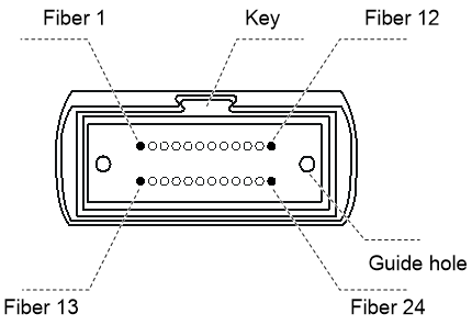
· Multi-fiber Push On connector (MPO).
H3C transceiver modules use only female MPO connectors, which have guide holes in the end face.
MPO connectors are classified as the following types based on the polish type:
¡ Physical contact (PC)—End face polished flat.
¡ Angle-polished contact (APC)—End face polished with an angle, typically 8°.
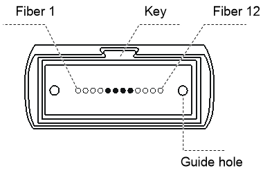
MPO connectors are available with 12 fibers, 16 fibers, or 24 fibers:
¡ 12-fiber MPO connector
Figure 4 End face of a 12-fiber connector
¡ 16-fiber MPO connector
Figure 5 End face of a 16-fiber connector

¡ 24-fiber MPO connector
Figure 6 End face of a 24-fiber connector
Optical specifications
|
|
CAUTION: The average transmit power of a long-haul optical transceiver module is greater than the saturated optical power. Be careful about the length of the optical fiber you use to make sure the actual receive power reaching the optical transceiver module is less than its saturated optical power. Otherwise, the optical transceiver module might be damaged. |
|
|
NOTE: Average transmit and receive power ranges are provided for transceiver modules in this guide. |
Transmit power
Transmit power is the power at which the transmitter of an optical transceiver module transmits optical signals, in dBm.
Receive power
Receive power is the power at which the receiver of an optical transceiver module receives optical signals, in dBm.
Receiving sensitivity
Receiving sensitivity is the minimum optical power that is needed at the receiving end for the optical module to receive optical signals at a given data rate and bit error rate, in dBm. The higher the data rate is, the worse the receiving sensitivity is, the greater the minimum receive power is. A greater receive power has higher requirements on the receiving components of the optical module.
Saturated optical power
Saturated optical power (also known as optical saturation) is the maximum receive power at a given data rate and bit error rate range (10-10 to 10-12), in dBm.
Copper transceiver modules
Copper transceiver modules, also called RJ-45 modules, transmit electrical signals over twisted pair cables and do not provide conversion between electrical and optical signals. Compared with optical fibers, twisted pair cables provide a short transmission distance, suitable only for small-scale networking environments.
You can use copper transceiver modules to connect two fiber ports over a network cable.
H3C devices support SFP and SFP+ copper transceiver modules.
Data rate
10 Gbps, 1250 Mbps, and 100 Mbps copper transceiver modules are available for H3C devices.
Transmission distance
Through UTP cables, electrical signals can be transmitted over a distance of 100 m (328.08 ft) only. This is because electrical signals attenuate during transmission through the UTP cables.
Attenuation refers to the dissipation of the power of a transmitted signal as it travels over a cable. Attenuation occurs because signal transmission suffers certain resistance from the cable, which weakens the electrical signals as they travel over the cable. When signals are transmitted over a very long distance, signal strength decreases very significantly, causing the signal-to-noise ratio to drop below the accepted level. This makes it impossible to distinguish between signals and noise, resulting in decision errors.
To transmit signals over a short distance, use copper transceiver modules only.
Connector
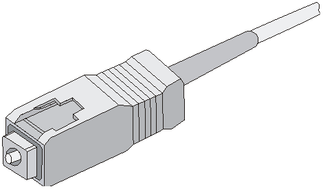
RJ-45 (Registered Jack-45) twisted pair connectors are used as the connectors for copper transceiver modules. Figure 7 shows the appearance of an RJ-45 connector.
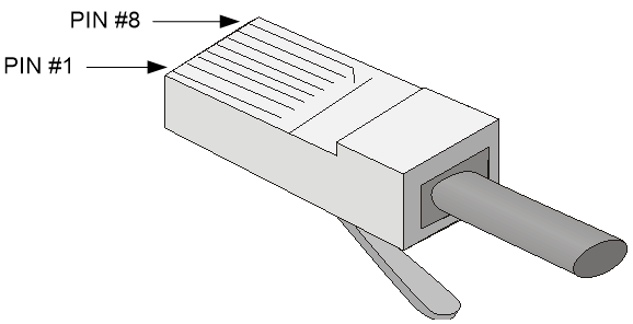
Table 5 RJ-45 GE connector pin assignment
|
Pin |
Signal |
Function |
|
|
1 |
MX_0+ |
Data transmit/receive |
|
|
2 |
MX_0- |
Data transmit/receive |
|
|
3 |
MX_1+ |
Data transmit/receive |
|
|
4 |
MX_2+ |
Data transmit/receive |
|
|
5 |
MX_2- |
Data transmit/receive |
|
|
6 |
MX_1- |
Data transmit/receive |
|
|
7 |
MX_3+ |
Data transmit/receive |
|
|
8 |
MX_3- |
Data transmit/receive |
|
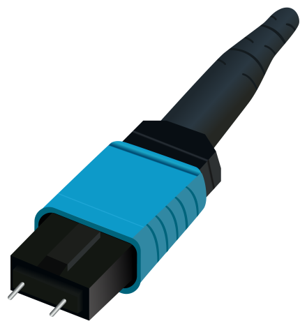
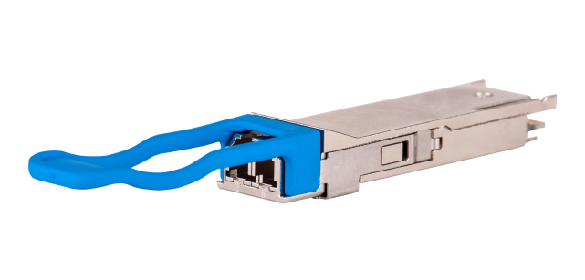
Hybrid copper-fiber transceiver modules
A hybrid copper-fiber transceiver module is typically used to connect a hybrid copper-fiber cable to an optical host in a hybrid fiber-copper deployment. Compared with common transceiver modules, a hybrid copper-fiber transceiver module can transmit data over an optical fiber and power over a copper cable. A hybrid copper-fiber transceiver module must be used together with a hybrid copper-fiber cable, hybrid fiber-copper pigtail, and hybrid copper-fiber interface (such as PSFP or PSFP+ interface) for data and power transmission. The transmission method of hybrid copper-fiber transceiver module in combination with the hybrid copper-fiber cable greatly extends the power supply and data transmission distance compared to the twisted pair transmission method, applicable for large-scale network environments.
H3C devices support SFP and SFP+ hybrid copper-fiber transceiver modules.
Data rate
Data rate refers to the number of bits transmitted per second, measured in Mbps or Gbps. The hybrid copper-fiber transceiver module supported by H3C devices mainly provide the following transmission rates: 10 Gbps, 5000 Mbps, 2500 Mbps, and 1250 Mbps.
Transmission distance
The transmission distance of hybrid copper-fiber transceiver modules is divided into short and long-range types. A distance of 2 km (1.24 miles) and below is generally considered as short-range type. 10 km (6.21 miles) is considered as long-range type.
Transmission distances provided by hybrid copper-fiber transceiver modules are limited by the following factors:
· Certain loss and dispersion suffered during the transmission of optical signals over optical fibers in hybrid copper-fiber cables.
¡ Loss is the optical energy loss due to the absorption, dispersion and leakage over the media when light travels through optical fibers. This loss increases in direct ratio to transmission distance.
¡ Dispersion happens mainly because electromagnetic waves of different wavelengths travel at different rates over the same medium, causing different wave components of optical signals to reach the receiving end early or late as the transmission distance increases, which in turn causes impulse broadening, making the signal values indistinguishable.
· Power of the power supply ports on the optical switch. A longer transmission distance indicates more power consumption for the powered devices and larger power for the power supply ports.
· Cable impedance. A longer transmission distance indicates larger cable impedance and larger power for the power supply ports.
· Total power consumption of the remote powered devices (PDs) and wireless APs and PDs that connect to the remote PDs.
Choose compatible hybrid copper-fiber transceiver modules, pigtails, and hybrid copper-fiber cables as required.
Central wavelength
Central wavelength represents the wave band used for optical signal transmission. Currently, the central wavelength used by H3C hybrid copper-fiber transceiver modules is 1310 nm.
Fiber
H3C hybrid copper-fiber transceiver modules use single-mode optical fibers (SMFs). For more information, see "Fiber."
Connector
|
|
CAUTION: · Cover the connector with a dust cap when it is not connected to any optical fiber. · You can insert only a Power Ethernet Lucent connectors (PELC) connector, not an LC connector, into a hybrid copper-fiber transceiver module. |
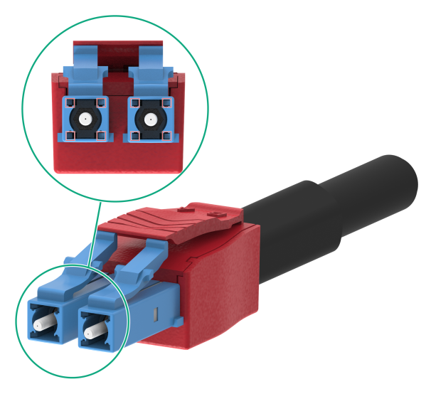
H3C hybrid copper-fiber transceiver modules use PELC connectors. With conductive terminals, a PELC connector can provide high-speed and long-range data transmission and supply power for remote devices. As shown in Figure 8, the parts marked in small red square boxes are conductive terminals.
Optical specifications
Hybrid copper-fiber transceiver modules have the same optical specifications as common optical transceiver modules. For more information, see "Optical specifications."
H3C iOptic 3.0 transceiver modules
Introduction
H3C iOptic 3.0 dedicated transceiver module, similar to the hybrid copper-fiber transceiver module, is used to connect a hybrid copper-fiber cable and an optical host for long-distance power and data transmission. However, significant differences exist between the iOptic 3.0 dedicated transceiver module, hybrid copper-fiber transceiver module, and ordinary transceiver module in terms of use method, appearance, and connector, as descripted in Table 6.
Table 6 Differences between ordinary transceiver modules, hybrid copper-fiber transceiver modules, and iOptic 3.0 transceiver modules
|
Transceiver module type |
Whether it can supply or receive power |
Connector |
Physical Identification |
Remarks |
|
Ordinary transceiver module |
No |
LC MPO |
No special identification. |
No special requirements. |
|
Hybrid copper-fiber transceiver module |
Yes |
PELC |
The metal pull handle of the transceiver module is red. |
It must be used in conjunction with a hybrid copper-fiber pigtail, hybrid copper-fiber cable, and hybrid copper-fiber interface for simultaneous transmission of power and data. |
|
iOptic 3.0 transceiver module |
Yes |
LC |
Words "All-Optical 3.0" are printed on the colored QR code label affixed to the transceiver module. |
The iOptic 3.0 transceiver module itself does not support power supply/reception. It must be used in conjunction with the combined fiber-copper pigtail, hybrid copper-fiber cable, and combined copper-fiber interface for simultaneous transmission of power and data. |
H3C devices support SFP28, SFP+, and SFP iOptic 3.0 dedicated transceiver modules.
Data rate
Data rate refers to the number of bits transmitted per second, measured in Mbps or Gbps. The iOptic 3.0 dedicated transceiver modules supported by H3C devices mainly provide the following transmission rates: 25 Gbps, 10 Gbps, 2500 Mbps, and 1250 Mbps.
Transmission distance
The transmission distance of iOptic 3.0 dedicated transceiver modules is divided into short and long-range types. A distance of 2 km (1.24 miles) and below is generally considered as short-range type. 10 km (6.21 miles) is considered as long-range type.
Transmission distances provided by iOptic 3.0 dedicated transceiver modules are limited by the following factors:
· Certain loss and dispersion suffered during the transmission of optical signals over optical fibers in hybrid copper-fiber cables.
¡ Loss is the optical energy loss due to the absorption, dispersion and leakage over the media when light travels through optical fibers. This loss increases in direct ratio to transmission distance.
¡ Dispersion happens mainly because electromagnetic waves of different wavelengths travel at different rates over the same medium, causing different wave components of optical signals to reach the receiving end early or late as the transmission distance increases, which in turn causes impulse broadening, making the signal values indistinguishable.
· Power of the power supply ports on the optical host. A longer transmission distance indicates more power consumption for the powered devices and larger power for the power supply ports.
· Cable impedance. A longer transmission distance indicates larger cable impedance and larger power for the power supply ports.
· Total power consumption of the remote powered devices (PDs) and wireless APs and PDs that connect to the remote PDs.
Choose compatible iOptic 3.0 dedicated transceiver modules, pigtails, and hybrid copper-fiber cables as required.
Central wavelength
Central wavelength represents the wave band used for optical signal transmission. Currently, the Central wavelength used by H3C iOptic 3.0 dedicated transceiver modules is 1310 nm.
Fiber
H3C iOptic 3.0 dedicated transceiver modules use single-mode optical fibers (SMFs). For more information, see "Fiber."
Connector
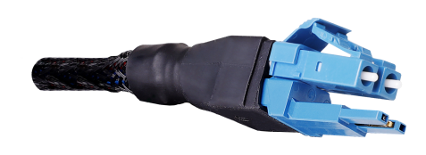
The H3C iOptic 3.0 dedicated transceiver module supports using an LC connector for data transmission. When it is used with a combined copper-fiber interface, you can use a Power over Double Lucent connector (PoDLC) connector for data transmission and power supply/reception. Compared with to an ordinary LC connector, a PoDLC connector has two parts. The upper part is an LC connector, similar to a regular LC connector, used to connect the iOptic 3.0 dedicated transceiver module. The lower part is a conductive terminal, used to connect the PoE interface (terminal block) of the iOptic host.
|
|
NOTE: An ordinary LC transceiver module does not support working in conjunction with a combined copper-fiber interface for data transmission and power supply/reception with a PoDLC connector. |
Figure 9 PoDLC connector
Optical specifications
The optical specifications of the iOptic 3.0 dedicated transceiver modules are the same as those of the ordinary transceiver modules. For more information, see "Optical specifications."
Immersive liquid-cooled transceiver modules
Introduction
The immersive liquid-cooled transceiver module, abbreviated as liquid-cooled transceiver module, is typically used to connect an immersive liquid-cooled device to another device. Differences exist between liquid-cooled transceiver modules and ordinary transceiver modules, as shown in Table 7.
Table 7 Differences between liquid-cooled transceiver modules and ordinary transceiver modules
|
Transceiver module type |
Transmission medium |
Physical identification |
Use method |
|
Ordinary transceiver module |
Optical fiber |
No special identification. |
Insert it into a fiber port and then connect a fiber optic connector to it. |
|
Liquid-cooled transceiver modules |
Optical fiber |
The transceiver module is integrated with the pigtail, and the pigtail connector is an MPO male connector. |
· It must be used in conjunction with an MPO adapter or a wiring rack that supports MPO adapters. · The transceiver module body will be completely immersed in the liquid during use. · Be careful not to immerse the MPO connector part into the liquid. |
H3C devices support multiple liquid-cooled transceiver modules that are different in specifications. You can choose the appropriate liquid-cooled transceiver module as needed and connect an optical fiber to it for data transmission.
The common packaging types of liquid-cooled transceiver modules are mainly QSFP28 and SFP28.
Data rate
Data rate refers to the number of bits transmitted per second, measured in Mbps or Gbps. The liquid-cool transceiver modules supported by H3C devices mainly provide a transmission rate of 100 Gbps.
Transmission distance
Currently, H3C liquid-cooled transceiver modules are mainly for short-distance transmission, with a transmission distance of 100 m (328.08 ft) or less.
Central wavelength
The center wavelength refers to the wave band used for optical signal transmission. Currently, the center wavelength of commonly used liquid-cooled transceiver modules is mainly 850 nm, which is often used for short-distance transmission.
Fiber
Currently, H3C liquid-cooled transceiver modules use multimode optical fibers (MMFs). For more information about optical fibers, see "Fiber."
Connector
H3C liquid-cooled transceiver module integrates the transceiver module and pigtail together, and the pigtail connector is an MPO male connector.
The MPO connector used by the H3C liquid-cooled transceiver module is a male connector with a guide pin. The MPO connector is a PC-polished, 12-core fiber MPO connector. For more information about the MPO connector, see "Connector."
Optical specifications
The optical specifications of H3C liquid-cooled transceiver modules are the same as those of the ordinary transceiver modules. For more information, see "Optical specifications."
Safety and Regulatory Compliance Information
Table 8 Safety and Regulatory Compliance Information
|
IEEE 802.3ab |
|
IEEE 802.3ah |
|
IEEE 802.3ak |
|
IEEE 802.3an |
|
IEEE 802.3av |
|
IEEE 802.3ba |
|
IEEE 802.3bj |
|
IEEE 802.3bm |
|
IEEE 802.3bs |
|
IEEE 802.3bz |
|
IEEE 802.3cd |
|
IEEE 802.3ck |
|
IEEE 802.3cn |
|
IEEE 802.3z |
|
SFF-8418 |
|
SFF-8431 |
|
SFF-8432 |
|
SFF-8472 |
|
SFF-8636 |
|
SFF-8661 |
|
SFF-8679 |
|
INF-8074 |
|
INF-8077 |
|
ITU-T G.957 |
|
ITU-T G.984 |
|
ITU-T G.988 |
|
QSFP-DD Hardware Rev 5.0 |
|
Common Management Interface Specification Rev 4.0 |
|
400G-LR4-10 Technical Specification Draft 1.0 |
|
CFP MSA Hardware Specification Revision 1.4 |
|
CFP MSA CFP2 Hardware Specification Draft Revision 0.3 |
|
CFP MSA Management Interface Specification Version 2.2 r06a |
|
IEC 61280-1-4 |
|
IEC 61754-7-2004 |
|
T-REC-G.595.1 |
|
GR-468-CORE-2004 |
|
RoHS compliant and lead-free per Directive 2011/65/EU |
|
UL |
|
CE |
|
Monitored by Digital Diadnostics Monitoring(DDM) |
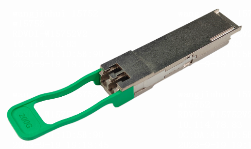
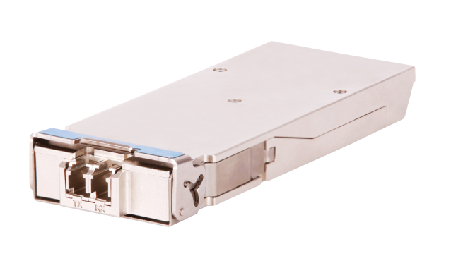
QSFP-DD modules
QSFP-DD optical transceiver modules (MPO interface)
Figure 11 QSFP-DD optical transceiver module (MPO interface)

Models and specifications
QSFP-DD optical transceiver modules (MPO) provide a transmission rate of 400 Gbps.
Table 9 Specifications for QSFP-DD optical transceiver modules (MPO) (1)
|
Model |
Central wavelength (nm) |
Fiber mode |
Fiber diameter (µm) |
Fiber cores |
Modal bandwidth (MHz*km) |
Transmission distance |
|
QSFPDD-400G-SR8-MM850 |
850 |
MMF |
50/125 |
16 |
2000 |
70 m (229.66 ft) |
|
4700 |
100 m (328.08 ft) |
Table 10 Specifications for QSFP-DD optical transceiver modules (MPO) (2)
|
Model |
Connector |
Optical parameters (dBm) |
|
|
Transmit power |
Receive power |
||
|
QSFPDD-400G-SR8-MM850 |
MPO (APC polished, 16-fiber) |
–6.5 to +4 |
–8.4 to +4 |
QSFP-DD optical transceiver modules (LC interface)
Figure 12 QSFP-DD optical transceiver module (LC interface)
Models and specifications
QSFP-DD optical transceiver modules (LC interface) provide a transmission rate of 400 Gbps.
Table 11 Specifications for QSFP-DD optical transceiver modules (LC interface) (1)
|
Model |
Central wavelength (nm) |
Fiber mode |
Fiber diameter (µm) |
Modal bandwidth (MHz*km) |
Transmission distance |
|
QSFPDD-400G-FR4-WDM1300 |
Four lanes: · 1271 · 1291 · 1311 · 1331 |
SMF |
9/125 |
N/A |
2 km (1.24 miles) |
|
QSFPDD-400G-LR4-WDM1300-DC |
Four lanes: · 1271 · 1291 · 1311 · 1331 |
SMF |
9/125 |
N/A |
6 km (3.73 miles, complying with the IEEE802.3cu standard) |
|
10 km (6.21 miles, complying with the 100G Lambda MSA standard) |
|||||
|
QSFPDD-400G-LR8-WDM1300 |
Four lanes: · 1273.54 · 1277.89 · 1282.26 · 1286.66 · 1295.56 · 1300.05 · 1304.58 · 1309.14 |
SMF |
9/125 |
N/A |
10 km (6.21 miles) |
Table 12 Specifications for QSFP-DD optical transceiver modules (LC interface) (2)
|
Model |
Optical parameters (dBm) |
|
|
Transmit power |
Receive power |
|
|
QSFPDD-400G-FR4-WDM1300 |
–3.2 to +4.4 |
–7.2 to +4.4 |
|
QSFPDD-400G-LR4-WDM1300-DC |
–2.7 to +5.1 |
–9.0 to +5.1 |
|
QSFPDD-400G-LR8-WDM1300 |
–2.8 to +5.3 |
–9.1 to +5.3 |
|
|
NOTE: The transmit power and receive power provided in Table 12 are average values of the four lanes. |
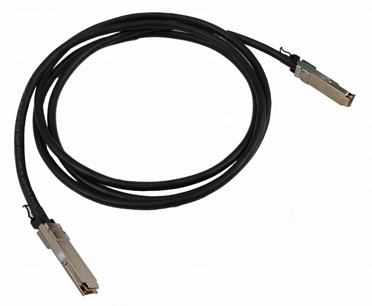
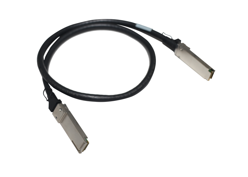
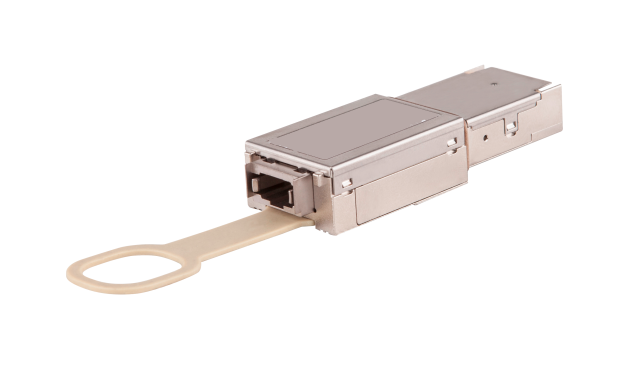
QSFP-DD copper cable
Figure 13 QSFP-DD copper cable
Models and specifications
Table 13 Specifications for QSFP-DD copper cables
|
Model |
Length |
Data rate |
|
QSFPDD-400G-D-CAB-2M |
2 m (6.56 ft) |
400 Gbps |
QSFP56 modules
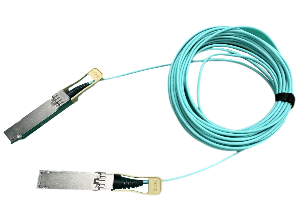
QSFP56 optical transceiver modules (MPO interface)
Figure 14 QSFP56 optical transceiver module (MPO interface)
Models and specifications
QSFP56 optical transceiver modules (MPO interface) provide a transmission rate of 200 Gbps and use an MPO connector.
Table 14 Specifications for QSFP56 optical transceiver modules (MPO interface) (1)
|
Model |
Central wavelength (nm) |
Fiber mode |
Fiber diameter (µm) |
Fiber cores |
Modal bandwidth (MHz*km) |
Transmission distance |
|
QSFP56-200G-SR4-MM850 |
850 |
MMF |
50/125 |
8 |
2000 |
70 m (229.66 ft) |
|
4700 |
100 m (328.08 ft) |
Table 15 Specifications for QSFP56 optical transceiver modules (MPO interface) (2)
|
Model |
Connector |
Optical parameters (dBm) |
|
|
Transmit power |
Receive power |
||
|
QSFP56-200G-SR4-MM850 |
MPO (PC polished, 12-fiber) |
–6.5 to +4 |
–8.4 to +4 |
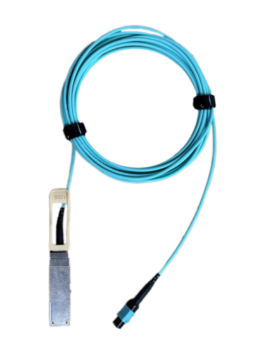
QSFP56 optical transceiver modules (LC interface)
Figure 15 QSFP56 optical transceiver module (LC interface)
Models and specifications
QSFP56 optical transceiver modules (LC interface) provide a transmission rate of 200 Gbps and use an LC connector.
Table 16 Specifications for QSFP56 optical transceiver modules (LC interface) (1)
|
Model |
Central wavelength (nm) |
Fiber mode |
Fiber diameter (µm) |
Modal bandwidth (MHz*km) |
Transmission distance |
|
QSFP56-200G-FR4-WDM1300 |
Four lanes: · 1271 · 1291 · 1311 · 1331 |
SMF |
9/125 |
N/A |
2 km (1.24 miles) |
Table 17 Specifications for QSFP56 optical transceiver modules (LC interface) (2)
|
Model |
Optical parameters (dBm) |
|
|
Transmit power |
Receive power |
|
|
QSFP56-200G-FR4-WDM1300 |
–4.2 to +4.7 |
–8.2 to +4.7 |
QSFP56 copper cables
Figure 16 QSFP56 copper cable
Models and specifications
Table 18 Specifications for QSFP56 copper cable
|
Model |
Length |
Data rate |
|
QSFP56-200G-D-DAC-1M |
1 m (3.28 ft) |
200 Gbps |
|
QSFP56-200G-D-DAC-2M |
2 m (6.56 ft) |
|
|
QSFP56-200G-D-DAC-3M |
3 m (9.84 ft) |
QSFP56 to QSFP56 copper cables
Figure 17 QSFP56 to QSFP56 copper cable
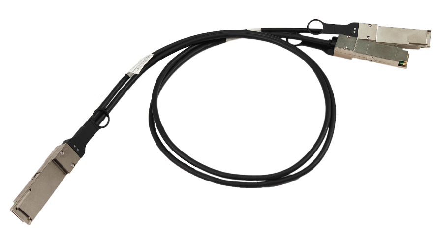
Models and specifications
Table 19 Specifications for QSFP56 to QSFP56 copper cables
|
Model |
Length |
Data rate |
Description |
|
QSFP56-200G-2QSFP56-100G-DAC-1m |
1 m (3.28 ft) |
200 Gbps |
Used for connecting a 200G QSFP56 port to two 100G QSFP56 ports. |
|
QSFP56-200G-2QSFP56-100G-DAC-2m |
2 m (6.56 ft) |
||
|
QSFP56-200G-2QSFP56-100G-DAC-3m |
3 m (9.84 ft) |
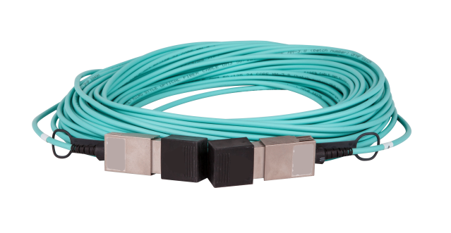
QSFP56 to QSFP56 fiber cables
Figure 18 QSFP56 to QSFP56 fiber cable
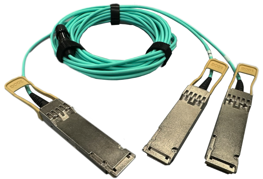
Models and specifications
Table 20 Specifications for QSFP56 to QSFP56 fiber cables
|
Model |
Length |
Data rate |
Description |
|
QSFP56-200G-2QSFP56-100G-AOC-5m |
5 m (16.40 ft) |
200 Gbps |
Used for connecting a 200G QSFP56 port to two 100G QSFP56 ports. |
|
QSFP56-200G-2QSFP56-100G-AOC-7m |
7 m (22.97 ft) |
||
|
QSFP56-200G-2QSFP56-100G-AOC-10m |
10 m (32.81 ft) |
||
|
QSFP56-200G-2QSFP56-100G-AOC-20m |
20 m (65.62 ft) |
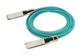
QSFP56 fiber cables
Figure 19 QSFP56 fiber cable
Models and specifications
Table 21 Specifications for QSFP56 fiber cables
|
Model |
Length |
Data rate |
|
QSFP56-200G-D-AOC-5M |
5 m (16.40 ft) |
200 Gbps |
|
QSFP56-200G-D-AOC-7M |
7 m (22.97 ft) |
|
|
QSFP56-200G-D-AOC-10M |
10 m (32.81 ft) |
|
|
QSFP56-200G-D-AOC-20M |
20 m (65.62 ft) |
QSFP28 modules
QSFP28 optical transceiver modules (MPO interface)
Figure 20 QSFP28 optical transceiver module (MPO interface)
Models and specifications
QSFP28 optical transceiver modules (MPO interface) provide a transmission rate of 100 Gbps and use an MPO connector.
Table 22 Specifications for QSFP28 optical transceiver modules (MPO interface) (1)
|
Model |
Central wavelength (nm) |
Fiber mode |
Fiber diameter (µm) |
Fiber cores |
Modal bandwidth (MHz*km) |
Transmission distance |
|
QSFP-100G-SR4-MM850 |
850 |
MMF |
50/125 |
8 |
2000 |
70 m (229.66 ft) |
|
4700 |
100 m (328.08 ft) |
|||||
|
QSFP-100G-SR4-MM850-H |
850 |
MMF |
50/125 |
8 |
2000 |
70 m (229.66 ft) |
|
4700 |
100 m (328.08 ft) |
|||||
|
QSFP-100G-SR4-MM850-B-CM |
850 |
MMF |
50/125 |
8 |
2000 |
70 m (229.66 ft) |
|
4700 |
100 m (328.08 ft) |
|||||
|
QSFP-100G-SR4-MM850-CM |
850 |
MMF |
50/125 |
8 |
2000 |
70 m (229.66 ft) |
|
4700 |
100 m (328.08 ft) |
|||||
|
QSFP-100G-SR4-MM850-A |
850 |
MMF |
50/125 |
8 |
2000 |
70 m (229.66 ft) |
|
4700 |
100 m (328.08 ft) |
|||||
|
QSFP-100G-eSR4-MM850 |
850 |
MMF |
50/125 |
8 |
4700 |
300 m (984.25 ft) |
|
QSFP-100G-PSM4-SM1310 |
1310 |
SMF |
9/125 |
8 |
N/A |
0.5 km (0.31 miles) |
Table 23 Specifications for QSFP28 optical transceiver modules (MPO interface) (2)
|
Model |
Connector |
Optical parameters (dBm) |
|
|
Transmit power |
Receive power |
||
|
QSFP-100G-SR4-MM850 |
MPO (PC polished, 12-fiber) |
–8.4 to +2.4 |
–10.3 to +2.4 |
|
QSFP-100G-SR4-MM850-H |
MPO (PC polished, 12-fiber) |
–8.4 to +2.4 |
–10.3 to +2.4 |
|
QSFP-100G-SR4-MM850-B-CM |
MPO (PC polished, 12-fiber) |
–2 to +2.4 |
–10.3 to +2.4 |
|
QSFP-100G-SR4-MM850-CM |
MPO (PC polished, 12-fiber) |
–8.4 to +2.4 |
–10.3 to +2.4 |
|
QSFP-100G-SR4-MM850-A |
MPO (PC polished, 12-fiber) |
–8.4 to +2.4 |
–10.3 to +2.4 |
|
QSFP-100G-eSR4-MM850 |
MPO (PC polished, 12-fiber) |
–8.4 to +2.4 |
–10.3 to +2.4 |
|
QSFP-100G-PSM4-SM1310 |
MPO (APC polished, 12-fiber) |
–9.4 to +2 |
–12.66 to +2 |
QSFP28 liquid-cooled transceiver modules (MPO interface)
Figure 21 QSFP28 liquid-cooled transceiver module (MPO interface)
Models and specifications
QSFP28 liquid-cooled transceiver modules (MPO interface) provide a transmission rate of 100 Gbps and use an MPO connector.
Table 24 Specifications for QSFP28 liquid-cooled transceiver modules (MPO interface) (1)
|
Model |
Central wavelength (nm) |
Fiber mode |
Fiber diameter (µm) |
Fiber cores |
Modal bandwidth (MHz*km) |
Transmission distance |
|
QSFP-100G-SR4-MM850-Y5 |
850 |
MMF |
50/125 |
8 |
2000 |
70 m (229.66 ft) |
|
4700 |
100 m (328.08 ft) |
|
|
CAUTION: The operating outer casing temperature range of liquid-cooled transceiver modules is 10°C to 60°C (50°F to 140°F). |
Table 25 Specifications for QSFP28 liquid-cooled transceiver modules (MPO interface) (2)
|
Model |
Connector |
Optical parameters (dBm) |
|
|
Transmit power |
Receive power |
||
|
QSFP-100G-SR4-MM850-Y5 |
MPO (PC polished, 12-fiber) |
–8.4 to +2.4 |
–10.3 to +2.4 |
QSFP28 optical transceiver modules (LC interface)
Figure 22 QSFP28 optical transceiver module (LC interface)
Models and specifications
QSFP28 optical transceiver modules (LC interface) in Table 26 and Table 27 provide a transmission rate of 100 Gbps and 50 Gbps, respectively. The QSFP28 optical transceiver modules use an LC connector.
Table 26 Specifications for QSFP28 optical transceiver modules (LC interface) (1)
|
Model |
Central wavelength (nm) |
Fiber mode |
Fiber diameter (µm) |
Modal bandwidth (MHz*km) |
Transmission distance |
|
QSFP-100G-ER4L-WDM1300 |
Four lanes: · 1295.56 · 1300.05 · 1304.58 · 1309.14 |
SMF |
9/125 |
N/A |
40 km (24.86 miles) |
|
QSFP-100G-ER4-WDM1300 |
Four lanes: · 1295.56 · 1300.05 · 1304.58 · 1309.14 |
SMF |
9/125 |
N/A |
40 km (24.86 miles) |
|
QSFP-100G-LR4-WDM1300 |
Four lanes: · 1295.56 · 1300.05 · 1304.58 · 1309.14 |
SMF |
9/125 |
N/A |
10 km (6.21 miles) |
|
QSFP-100G-LR4-WDM1300-A |
Four lanes: · 1295.56 · 1300.05 · 1304.58 · 1309.14 |
SMF |
9/125 |
N/A |
10 km (6.21 miles) |
|
QSFP-100G-LR4L-WDM1300 |
Four lanes: · 1271 · 1291 · 1311 · 1331 |
SMF |
9/125 |
N/A |
2 km (1.24 miles) |
|
QSFP-100G-ZR4-WDM1300 |
Four lanes: · 1295.56 · 1300.05 · 1304.58 · 1309.14 |
SMF |
9/125 |
N/A |
80 km (49.71 miles) |
|
QSFP-100G-CWDM4-SM1300-A |
Four lanes: · 1271 · 1291 · 1311 · 1331 |
SMF |
9/125 |
N/A |
2 km (1.24 miles) |
|
QSFP-100G-SWDM4-MM850 |
Four lanes: · 850 · 880 · 910 · 940 |
MMF |
50/125 |
2000 |
75 m (246.06 ft) |
|
4700 |
100 m (328.08 ft) |
||||
|
QSFP-100G-BIDI-MM850 |
Four lanes: · 855 · 908 |
MMF |
50/125 |
2000 |
70 m (229.66 ft) |
|
4700 |
100 m (328.08 ft) |
Table 27 Specifications for QSFP28 optical transceiver modules (LC interface) (2)
|
Model |
Central wavelength (nm) |
Fiber mode |
Fiber diameter (µm) |
Modal bandwidth (MHz*km) |
Transmission distance |
|
QSFP-50G-LR-SM1311 |
1311 |
SMF |
9/125 |
N/A |
10 km (6.2 miles) |
|
QSFP-50G-ER-SM1311 |
1311 |
SMF |
9/125 |
N/A |
40 km (24.86 miles) |
Table 28 Specifications for QSFP28 optical transceiver modules (LC interface) (3)
|
Model |
Optical parameters (dBm) |
|
|
Transmit power (average) |
Receive power (average) |
|
|
QSFP-100G-ER4L-WDM1300 |
+0.5 to +4.5 per lane |
–20.5 to –1.9 per lane |
|
QSFP-100G-ER4-WDM1300 |
–2.9 to +2.9 per lane |
–20.9 to –3.5 per lane |
|
QSFP-100G-LR4-WDM1300 |
–4.3 to +4.5 per lane |
–10.6 to +4.5 per lane |
|
QSFP-100G-LR4-WDM1300-A |
–4.3 to +4.5 per lane |
–10.6 to +4.5 per lane |
|
QSFP-100G-LR4L-WDM1300 |
–6.5 to +2.5 per lane |
–11.5 to +2.5 per lane |
|
QSFP-100G-ZR4-WDM1300 |
+2 to +6.5 per lane |
–28 to –7 per lane |
|
QSFP-100G-CWDM4-SM1300-A |
–6.5 to +2.5 per lane |
–11.5 to +2.5 per lane |
|
QSFP-100G-SWDM4-MM850 |
–7.5 to +2.4 per lane |
–9.5 to +2.4 per lane |
|
QSFP-100G-BIDI-MM850 |
–6 to +4 per lane |
–7.9 to +4 per lane |
|
QSFP-50G-LR-SM1311 |
–4.5 to +4.2 per lane |
–10.8 to +4.2 per lane |
|
QSFP-50G-ER-SM1311 |
+0.4 to +6.6 per lane |
–17.6 to –3.4 per lane |
|
|
NOTE: · The operating outer casing temperature of a QSFP-100G-BIDI-MM850 transceiver module is in the range of 10°C to 60°C (50°F to 140°F). The performance, signal transmitting and receiving capability, and link status of the transceiver module deteriorate when the outer casing temperature is out of this range. · To use the QSFP-100G-ER4L-WDM1300 transceiver module to transmit data over a distance of 40 km (24.86 miles), you must enable FEC on the traffic transmitting and receiving ports. If FEC is not enabled on the peer ports, the transmission distance can only reach a maximum of 30 km (18.64 miles). |
QSFP28 copper cable
Figure 23 QSFP28 copper cable
Models and specifications
Table 29 Specifications for QSFP28 copper cables
|
Model |
Length |
Data rate |
|
QSFP-100G-D-CAB-1M |
1 m (3.28 ft) |
100 Gbps |
|
QSFP-100G-D-CAB-3M |
3 m (9.84 ft) |
|
|
QSFP-100G-D-CAB-3M-CM |
3 m (9.84 ft) |
|
|
QSFP-100G-D-CAB-5M |
5 m (16.40 ft) |
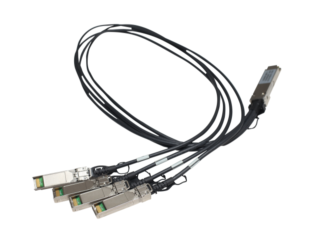
QSFP28 to SFP28 copper cables
A QSFP28 to SFP28 copper cable has a QSFP28 module at one end and four SFP28 modules at the other end.
Figure 24 QSFP28 to SFP28 copper cable

Models and specifications
Table 30 Specifications for QSFP28 to SFP28 copper cables
|
Model |
Length |
Data rate |
Remarks |
|
QSFP-100G-4SFP-25G-CAB-1M |
1 m (3.28 ft) |
100 Gbps |
Used for connecting one 100G QSFP28 port to four 25G SFP28 ports. |
|
QSFP-100G-4SFP-25G-CAB-3M |
3 m (9.84 ft) |
||
|
QSFP-100G-4SFP-25G-CAB-3M-CM |
3 m (9.84 ft) |
||
|
QSFP-100G-4SFP-25G-CAB-5M |
5 m (16.40 ft) |
||
|
QSFP-100G-4SFP-25G-CAB-5M-CM |
5 m (16.40 ft) |
QSFP28 fiber cables
Figure 25 QSFP28 fiber cable
Models and specifications
Table 31 Specifications for QSFP28 fiber cables
|
Model |
Length |
Data rate |
|
QSFP-100G-D-AOC-7M |
7 m (22.97 ft) |
100 Gbps |
|
QSFP-100G-D-AOC-7M-H |
7 m (22.97 ft) |
|
|
QSFP-100G-D-AOC-10M |
10 m (32.81 ft) |
|
|
QSFP-100G-D-AOC-10M-H |
10 m (32.81 ft) |
|
|
QSFP-100G-D-AOC-20M |
20 m (65.62 ft) |
|
|
QSFP-100G-D-AOC-20M-H |
20 m (65.62 ft) |
CFP modules
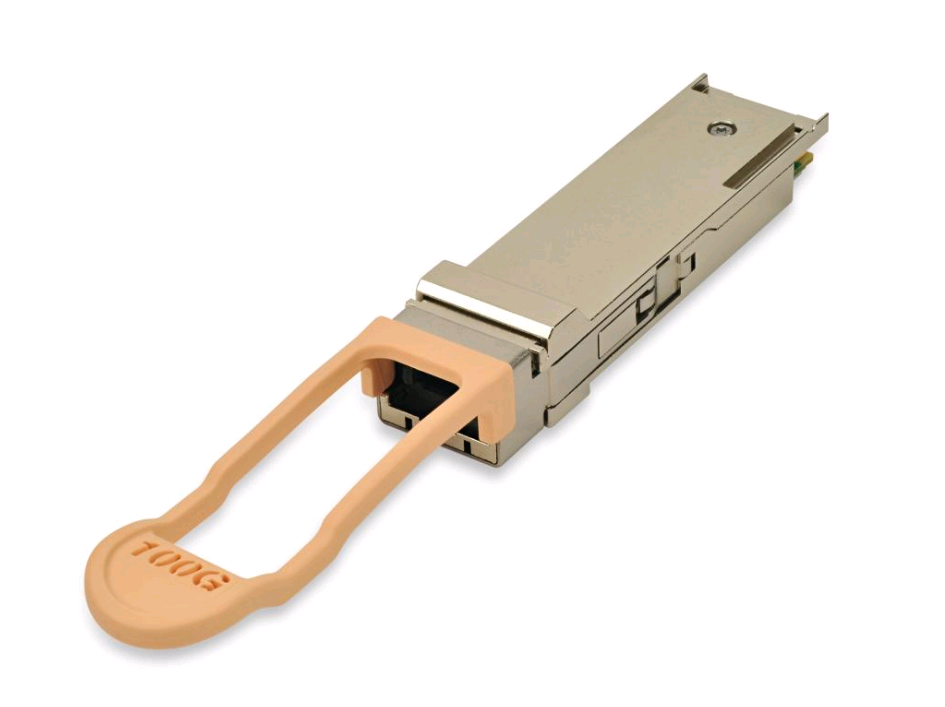
100-Gigabit CFP optical transceiver modules
Figure 26 100-Gigabit/40-Gigabit CFP optical transceiver module
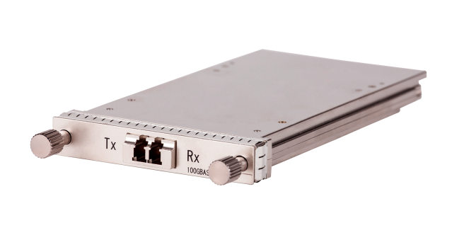
Models and specifications
100-Gigabit CFP optical transceiver modules provide a transmission rate of 100 Gbps and use LC connectors.
Table 32 Specifications for 100-Gigabit CFP optical transceiver modules (1)
|
Model |
Central wavelength (nm) |
Fiber mode |
Fiber diameter (µm) |
Transmission distance |
|
CFP-100G-LR4-WDM1300 (end of sale) |
Four lanes: · 1295.56 · 1300.05 · 1304.58 · 1309.14 |
SMF |
9/125 |
10 km (6.21 miles) |
|
CFP-100G-LR4-WDM1300-A |
Four lanes: · 1295.56 · 1300.05 · 1304.58 · 1309.14 |
SMF |
9/125 |
10 km (6.21 miles) |
|
CFP-100G-ER4-WDM1300 (end of sale) |
Four lanes: · 1295.56 · 1300.05 · 1304.58 · 1309.14 |
SMF |
9/125 |
40 km (24.86 miles) |
Table 33 Specifications for 100-Gigabit CFP optical transceiver modules (2)
|
Model |
Optical parameters (dBm) |
|
|
Transmit power (average) |
Receive power (average) |
|
|
CFP-100G-LR4-WDM1300 |
–4.3 to +4.5 |
–10.6 to +4.5 |
|
CFP-100G-LR4-WDM1300-A |
–4.3 to +4.5 |
–10.6 to +4.5 |
|
CFP-100G-ER4-WDM1300 |
–2.9 to +2.9 |
–20.9 to +4.5 |
40-Gigabit CFP optical transceiver modules
See Figure 26 for a view of the 40-Gigabit CFP optical transceiver module.
Models and specifications
40-Gigabit CFP optical transceiver modules provide a transmission rate of 40 Gbps and use a dual LC connector.
Table 34 Specifications for 40-Gigabit CFP optical transceiver modules (1)
|
Model |
Central wavelength (nm) |
Fiber mode |
Fiber diameter (µm) |
Transmission distance |
|
CFP-40G-LR4-SM1310 (end of sale) |
Four lanes: · 1271 · 1291 · 1311 · 1331 |
SMF |
9/125 |
10 km (6.21 miles) |
|
CFP-40G-ER4-WDM1300 (end of sale) |
Four lanes: · 1271 · 1291 · 1311 · 1331 |
SMF |
9/125 |
40 km (24.86 miles) |
Table 35 Specifications for 40-Gigabit CFP optical transceiver modules (2)
|
Model |
Optical parameters (dBm) |
|
|
Transmit power (average) |
Receive power (average) |
|
|
CFP-40G-LR4-SM1310 |
–4 to +3 |
–11.5 to +3 |
|
CFP-40G-ER4-WDM1300 |
–2.7 to +4.5 |
–21 to –4.5 |
CFP2 modules
CFP2 optical transceiver modules (MPO interface)
Figure 27 CFP2 optical transceiver module (MPO interface)
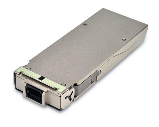
Models and specifications
CFP2 optical transceiver modules (MPO interface) provide a transmission rate of 100 Gbps and use an MPO connector.
Table 36 Specifications for CFP2 optical transceiver modules (MPO interface) (1)
|
Model |
Central wavelength (nm) |
Fiber mode |
Fiber diameter (µm) |
Fiber cores |
Modal bandwidth (MHz*km) |
Transmission distance |
|
CFP2-100G-SR10-MM850 |
850 |
MMF |
50/125 |
20 |
2000 |
100 m (328.08 ft) |
|
4700 |
150 m (492.13 ft) |
Table 37 Specifications for CFP2 optical transceiver modules (MPO interface) (2)
|
Model |
Connector |
Optical parameters (dBm) |
|
|
Transmit power |
Receive power |
||
|
CFP2-100G-SR10-MM850 |
MPO (PC polished, 24-fiber) |
–7.6 to +2.4 |
–9.5 to +2.4 |
CFP2 optical transceiver modules (LC interface)
Figure 28 CFP2 optical transceiver module (LC interface)
Models and specifications
CFP2 optical transceiver modules (LC interface) provide a transmission rate of 100 Gbps and use an LC connector.
Table 38 Specifications for CFP2 optical transceiver modules (LC interface) (1)
|
Model |
Central wavelength (nm) |
Fiber mode |
Fiber diameter (µm) |
Transmission distance |
|
CFP2-100G-LR4-WDM1300 |
Four lanes: · 1295.56 · 1300.05 · 1304.58 · 1309.14 |
SMF |
9/125 |
10 km (6.21 miles) |
|
CFP2-100G/112G-LR4-WDM1300 (end of sale) |
Four lanes: · 1295.56 · 1300.05 · 1304.58 · 1309.14 |
SMF |
9/125 |
10 km (6.21 miles) |
|
CFP2-100G-ER4-WDM1300 |
Four lanes: · 1295.56 · 1300.05 · 1304.58 · 1309.14 |
SMF |
9/125 |
40 km (24.86 miles) |
Table 39 Specifications for CFP2 optical transceiver modules (LC interface) (2)
|
Model |
Optical parameters (dBm) |
|
|
Transmit power (average) |
Receive power (average) |
|
|
CFP2-100G-LR4-WDM1300 |
–4.3 to +4.5 |
–10.6 to +4.5 |
|
CFP2-100G/112G-LR4-WDM1300 |
–4.3 to +4.5 |
–10.6 to +4.5 |
|
CFP2-100G-ER4-WDM1300 |
–2.7 to +2.9 |
–20.9 to +4.5 |
CXP modules
CXP optical transceiver modules
Figure 29 CXP optical transceiver module
Models and specifications
CXP optical transceiver modules provide a transmission rate of 100 Gbps and use an MPO connector.
Table 40 Specifications for CXP optical transceiver modules (1)
|
Model |
Central wavelength (nm) |
Fiber mode |
Fiber diameter (µm) |
Fiber cores |
Modal bandwidth (MHz*km) |
Transmission distance |
|
CXP-100G-SR10-MM850 (end of sale) |
850 |
MMF |
50/125 |
20 |
2000 |
100 m (328.08 ft) |
|
CXP-100G-SR10-MM850-A (end of sale) |
850 |
MMF |
50/125 |
20 |
2000 |
100 m (328.08 ft) |
Table 41 Specifications for CXP optical transceiver modules (2)
|
Model |
Connector |
Optical parameters (dBm) |
|
|
Transmit power |
Receive power |
||
|
CXP-100G-SR10-MM850 |
MPO (PC polished, 24-fiber) |
–7.6 to +2.4 |
–9.5 to +2.4 |
|
CXP-100G-SR10-MM850-A |
MPO (PC polished, 24-fiber) |
–7.6 to +2.4 |
–9.5 to +2.4 |
CXP fiber cables
Figure 30 CXP fiber cable
Models and specifications
Table 42 Specifications for CXP fiber cables
|
Model |
Length |
Transmission rate |
|
CXP-CXP-AOC-30M (end of sale) |
30 m (98.43 ft) |
100 Gbps |
|
CXP-CXP-AOC-10M (end of sale) |
10 m (32.81 ft) |
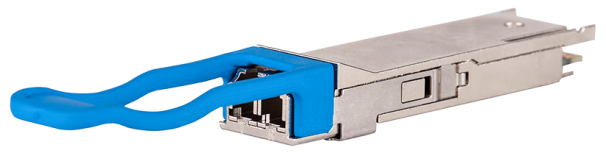
QSFP+ modules
QSFP+ optical transceiver modules (MPO interface)
Figure 31 QSFP+ optical transceiver module (MPO interface)
Models and specifications
QSFP+ optical transceiver modules (MPO interface) provide a transmission rate of 40 Gbps and use an MPO connector.
Table 43 Specifications for QSFP+ optical transceiver modules (MPO interface) (1)
|
Model |
Central wavelength (nm) |
Fiber mode |
Fiber diameter (µm) |
Fiber cores |
Modal bandwidth (MHz*km) |
Transmission distance |
|
QSFP-40G-SR4-MM850 |
850 |
MMF |
50/125 |
8 |
2000 |
100 m (328.08 ft) |
|
4700 |
150 m (492.13 ft) |
|||||
|
QSFP-40G-SR4-MM850-H |
850 |
MMF |
50/125 |
8 |
2000 |
100 m (328.08 ft) |
|
4700 |
150 m (492.13 ft) |
|||||
|
QSFP-40G-SR4-MM850-CM |
850 |
MMF |
50/125 |
8 |
2000 |
100 m (328.08 ft) |
|
4700 |
150 m (492.13 ft) |
|||||
|
QSFP-40G-SR4-MM850-NDDM (end of sale) |
850 |
MMF |
50/125 |
8 |
2000 |
100 m (328.08 ft) |
|
4700 |
150 m (492.13 ft) |
|||||
|
QSFP-40G-CSR4-MM850 |
850 |
MMF |
50/125 |
8 |
2000 |
300 m (984.25 ft) |
|
4700 |
400 m (1312.33 ft) |
|||||
|
QSFP-40G-CSR4-MM850-H |
850 |
MMF |
50/125 |
8 |
2000 |
300 m (984.25 ft) |
|
4700 |
400 m (1312.33 ft) |
|||||
|
QSFP-40G-CSR4-MM850-NDDM (end of sale) |
850 |
MMF |
50/125 |
8 |
2000 |
300 m (984.25 ft) |
|
4700 |
400 m (1312.33 ft) |
|||||
|
QSFP-40G-IR4-PSM1310 (end of sale) |
1310 |
SMF |
9/125 |
8 |
N/A |
1.4 km (0.87 miles) |
|
QSFP-40G-LR4-PSM1310 |
1310 |
SMF |
9/125 |
8 |
N/A |
10 km (6.21 miles) |
|
QSFP-40G-LR4-PSM1310-A |
1310 |
SMF |
9/125 |
8 |
N/A |
10 km (6.21 miles) |
Table 44 Specifications for QSFP+ optical transceiver modules (MPO interface) (2)
|
Model |
Connector |
Optical parameters (dBm) |
|
|
Transmit power |
Receive power |
||
|
QSFP-40G-SR4-MM850 |
MPO (PC polished, 12-fiber) |
–7.6 to 0 |
–9.5 to +2.4 |
|
QSFP-40G-SR4-MM850-H |
MPO (PC polished, 12-fiber) |
–7.6 to +2.4 |
–9.5 to +2.4 |
|
QSFP-40G-SR4-MM850-CM |
MPO (PC polished, 12-fiber) |
–7.6 to 0 |
–9.5 to +2.4 |
|
QSFP-40G-SR4-MM850-NDDM |
MPO (PC polished, 12-fiber) |
–7.6 to 0 |
–9.5 to +2.4 |
|
QSFP-40G-CSR4-MM850 |
MPO (PC polished, 12-fiber) |
–7.6 to 0 |
–9.9 to +2.4 |
|
QSFP-40G-CSR4-MM850-H |
MPO (PC polished, 12-fiber) |
–7.6 to +2.4 |
–9.9 to +2.4 |
|
QSFP-40G-CSR4-MM850-NDDM |
MPO (PC polished, 12-fiber) |
–7.6 to 0 |
–9.9 to +2.4 |
|
QSFP-40G-IR4-PSM1310 |
MPO (APC polished, 12-fiber) |
–6 to +0.5 |
–11.5 to +2.3 |
|
QSFP-40G-LR4-PSM1310 |
MPO (APC polished, 12-fiber) |
–8.2 to +1.5 |
–12.6 to +1.5 |
|
QSFP-40G-LR4-PSM1310-A |
MPO (APC polished, 12-fiber) |
–8.2 to +1.5 |
–12.6 to +1.5 |
|
|
NOTE: The 40G QSFP+ ports of the QSFP-40G-SR4-MM850, QSFP-40G-SR4-MM850-H, QSFP-40G-SR4-MM850-CM, QSFP-40G-SR4-MM850-NDDM, QSFP-40G-CSR4-MM850, QSFP-40G-CSR4-MM850-H, QSFP-40G-CSR4-MM850-NDDM, QSFP-40G-IR4-PSM1310, QSFP-40G-LR4-PSM1310, and QSFP-40G-LR4-PSM1310-A optical transceiver modules can be split into four channels. You can connect a 40G QSFP+ port to four 10G SFP+ ports. The QSFP+ optical transceiver module and SFP+ optical transceiver modules to be connected must be the same in specifications, including central wavelength and fiber type. |
QSFP+ optical transceiver modules (LC interface)
Figure 32 QSFP+ optical transceiver module (LC interface)
Models and specifications
QSFP+ optical transceiver modules (LC interface) provide a transmission rate of 40 Gbps and use a dual LC connector.
Table 45 Specifications for QSFP+ transceiver modules (LC interface) (1)
|
Model |
Central wavelength (nm) |
Fiber mode |
Fiber diameter (µm) |
Modal bandwidth (MHz*km) |
Transmission distance |
|
QSFP-40G-LR4-WDM1300 |
Four lanes: · 1271 · 1291 · 1311 · 1331 |
SMF |
9/125 |
N/A |
10 km (6.21 miles) |
|
QSFP-40G-LR4L-WDM1300 |
Four lanes: · 1271 · 1291 · 1311 · 1331 |
SMF |
9/125 |
N/A |
2 km (1.24 miles) |
|
QSFP-40G-ER4-WDM1300 |
Four lanes: · 1271 · 1291 · 1311 · 1331 |
SMF |
9/125 |
N/A |
40 km (24.86 miles) |
|
QSFP-40G-LX4-WDM1300 |
Four lanes: · 1271 · 1291 · 1311 · 1331 |
MMF |
50/125 |
2000 |
150 m (492.13 ft) |
|
4700 |
|||||
|
QSFP-40G-BIDI-SR-MM850 |
Two lanes: · 850 · 900 |
MMF |
50/125 |
2000 |
100 m (328.08 ft) |
|
4700 |
150 m (492.13 ft) |
||||
|
QSFP-40G-BIDI-WDM1310 (end of sale) |
Two lanes: · 1271 · 1291 · 1311 · 1331 |
MMF |
50/125 |
2000 |
140 m (459.32 ft) |
|
4700 |
160 m (524.93 ft) |
||||
|
QSFP-40G-BIDI-WDM850 |
Two lanes: · 850 · 880 · 910 · 940 |
MMF |
50/125 |
2000 |
240 m (787.40 ft) |
|
4700 |
350 m (1148.29 ft) |
Table 46 Specifications for QSFP+ transceiver modules (LC interface) (2)
|
Model |
Optical parameters (dBm) |
|
|
Transmit power (average) |
Receive power (average) |
|
|
QSFP-40G-LR4-WDM1300 |
–7 to +2.3 |
–13.7 to +2.3 |
|
QSFP-40G-LR4L-WDM1300 |
–10 to +2.3 |
–11.5 to +2.3 |
|
QSFP-40G-ER4-WDM1300 |
–2.7 to +4.5 |
–21.2 to –4.5 |
|
QSFP-40G-LX4-WDM1300 |
–5 to +3.5 |
–10.5 to +3.5 |
|
QSFP-40G-BIDI-SR-MM850 |
–4 to +5 |
–6 to +5 |
|
QSFP-40G-BIDI-WDM1310 |
–7 to +4.3 |
–10 to +4.3 |
|
QSFP-40G-BIDI-WDM850 |
–7.6 to +3 |
–9 to +3 |
|
|
NOTE: · The operating outer casing temperature of a QSFP-40G-BIDI-SR-MM850 transceiver module is in the range of 10°C to 70°C (50°F to 158°F). The performance, signal transmitting and receiving capability, and link status of the transceiver module deteriorate when the outer casing temperature is out of this range. · The display transceiver diagnosis command displays the current values of the digital diagnosis parameters on transceiver modules. However, if you use this command for a port in which a QSFP-40G-BIDI-SR-MM850 transceiver module is installed, the transmit and receive power of the transceiver module will not be displayed. · In the scenario where optical distribution frames (ODFs) are used, the transmission line from a QSFP-40G-LX4-WDM1300 transceiver module can pass through only one ODF if the ODFs use MPO interfaces and can pass through two ODFs if the ODFs use LC interfaces. |
QSFP+ copper cables
Figure 33 QSFP+ copper cable

Models and specifications
Table 47 Specifications for QSFP+ copper cables
|
Model |
Length |
Data rate |
Type |
Remarks |
|
LSWM1QSTK0 |
1 m (3.28 ft) |
40 Gbps |
QSFP+ copper cable |
Used for interconnecting 40-Gigabit QSFP+ ports |
|
LSWM1QSTK1 |
3 m (9.84 ft) |
|||
|
QSFP-40G-3M-CM |
3 m (9.84 ft) |
|||
|
LSWM1QSTK2 |
5 m (16.40 ft) |
|||
|
QSFP-40G-5M-CM |
5 m (16.40 ft) |
QSFP+ to SFP+ copper cables
One end of a QSFP+ to SFP+ copper cable provides a QSFP+ module, and the other end provides four SFP+ modules.
Figure 34 QSFP+ to SFP+ copper cable
Models and specifications
Table 48 Specifications for QSFP+ to SFP+ copper cables
|
Model |
Length |
Data rate |
Cable type |
Remarks |
|
LSWM1QSTK3 |
1 m (3.28 ft) |
40 Gbps |
40G QSFP+ to 4 x 10G SFP+ copper cable |
Used for connecting a 40-Gigabit QSFP+ port to four 10-Gigabit SFP+ ports |
|
LSWM1QSTK4 |
3 m (9.84 ft) |
|||
|
QSFP-40G-4SFP-10G-CAB-3M-CM |
3 m (9.84 ft) |
|||
|
LSWM1QSTK5 |
5 m (16.40 ft) |
|||
|
QSFP-40G-4SFP-10G-CAB-5M-CM |
5 m (16.40 ft) |
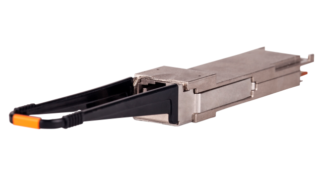
QSFP+ fiber cables
Figure 35 QSFP+ fiber cable
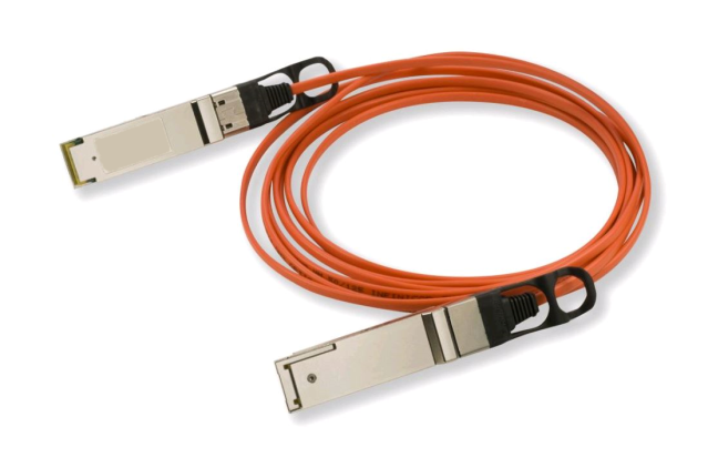
Models and specifications
Table 49 Specifications for QSFP+ fiber cables
|
Model |
Length |
Data rate |
|
QSFP-40G-D-AOC-3M |
3 m (9.84 ft) |
40 Gbps |
|
QSFP-40G-D-AOC-7M |
7 m (22.97 ft) |
|
|
QSFP-40G-D-AOC-7M-H |
7 m (22.97 ft) |
|
|
QSFP-40G-D-AOC-7M-CM |
7 m (22.97 ft) |
|
|
QSFP-40G-D-AOC-10M |
10 m (32.81 ft) |
|
|
QSFP-40G-D-AOC-10M-H |
10 m (32.81 ft) |
|
|
QSFP-40G-D-AOC-10M-CM |
10 m (32.81 ft) |
|
|
QSFP-40G-D-AOC-20M |
20 m (65.62 ft) |
|
|
QSFP-40G-D-AOC-20M-H |
20 m (65.62 ft) |
|
|
QSFP-40G-D-AOC-20M-CM |
20 m (65.62 ft) |
SFP28 modules
SFP28 optical transceiver modules
Figure 36 SFP28 optical transceiver module
Models and specifications
SFP28 optical transceiver modules provide a transmission rate of 25 Gbps and use a dual LC connector.
Table 50 Specifications for SFP28 transceiver modules (1)
|
Model |
Central wavelength (nm) |
Fiber mode |
Fiber diameter (µm) |
Modal bandwidth (MHz*km) |
Transmission distance |
|
SFP-25G-SR-MM850 |
850 |
MMF |
50/125 |
2000 |
70 m (229.66 ft) |
|
4700 |
100 m (328.08 ft) |
||||
|
SFP-25G-SR-MM850-H |
850 |
MMF |
50/125 |
2000 |
70 m (229.66 ft) |
|
4700 |
100 m (328.08 ft) |
||||
|
SFP-25G-LR-SM1310 |
1310 |
SMF |
9/125 |
N/A |
10 km (6.21 miles) |
|
*SFP-25G-LR-SM1310-I |
1310 |
SMF |
9/125 |
N/A |
10 km (6.21 miles) |
|
SFP-25G-CSR-MM850 |
850 |
MMF |
50/125 |
2000 |
200 m (656.17 ft) |
|
> 3500 |
300 m (984.25 ft) |
||||
|
> 5500 |
400 m (1312.34 ft) |
Table 51 Specifications for SFP28 transceiver modules (2)
|
Model |
Optical parameters (dBm) |
|
|
Transmit power |
Receive power |
|
|
SFP-25G-SR-MM850 |
–8.4 to +2.4 |
–10.3 to +2.4 |
|
SFP-25G-SR-MM850-H |
–8.4 to +2.4 |
–10.3 to +2.4 |
|
SFP-25G-LR-SM1310 |
–7 to +2 |
–13.3 to +2 |
|
*SFP-25G-LR-SM1310-I |
–7 to +2 |
–13.3 to +2 |
|
SFP-25G-CSR-MM850 |
–6.4 to +2.4 |
–10.3 to +2.4 |
SFP28 copper cables
Figure 37 SFP28 copper cable
Models and specifications
Table 52 Specifications for SFP28 copper cables
|
Model |
Length |
Data rate |
|
SFP-25G-D-CAB-1M |
1 m (3.28 ft) |
25 Gbps |
|
SFP-25G-D-CAB-1M-A |
1 m (3.28 ft) |
|
|
SFP-25G-D-CAB-2M-A |
2 m (6.56 ft) |
|
|
SFP-25G-D-CAB-3M |
3 m (9.84 ft) |
|
|
SFP-25G-D-CAB-3M-CM |
3 m (9.84 ft) |
|
|
SFP-25G-D-CAB-3M-A |
3 m (9.84 ft) |
|
|
SFP-25G-D-CAB-3M-Y |
3 m (9.84 ft) |
|
|
SFP-25G-D-CAB-4M-A |
4 m (13.12 ft) |
|
|
SFP-25G-D-CAB-5M |
5 m (16.40 ft) |
|
|
SFP-25G-D-CAB-5M-A |
5 m (16.40 ft) |
|
|
SFP-25G-D-CAB-5M-Y |
5 m (16.40 ft) |
|
|
SFP-25G-D-ACC-7M |
7 m (22.97 ft) |
|
|
SFP-25G-D-ACC-10M |
10 m (32.81 ft) |
|
|
CAUTION: The SFP-25G-D-CAB-3M-Y and SFP-25G-D-CAB-5M-Y are liquid-cooled copper cables. The transceiver module operating casing temperature range is 10°C to 60°C (50°F to 140°F). |
SFP28 fiber cables
Figure 38 SFP28 fiber cable

Models and specifications
Table 53 Specifications for SFP28 fiber cables
|
Model |
Length |
Data rate |
|
SFP-25G-D-AOC-3M |
3 m (9.84 ft) |
25 Gbps |
|
SFP-25G-D-AOC-5M |
5 m (16.40 ft) |
|
|
SFP-25G-D-AOC-5M-H |
5 m (16.40 ft) |
|
|
SFP-25G-D-AOC-5M-DG |
5 m (16.40 ft) |
|
|
SFP-25G-D-AOC-5M-DT (end of sale) |
5 m (16.40 ft) |
|
|
SFP-25G-D-AOC-7M |
7 m (22.97 ft) |
|
|
SFP-25G-D-AOC-7M-H |
7 m (22.97 ft) |
|
|
SFP-25G-D-AOC-7M-DG |
7 m (22.97 ft) |
|
|
SFP-25G-D-AOC-7M-DT (end of sale) |
7 m (22.97 ft) |
|
|
SFP-25G-D-AOC-10M |
10 m (32.81 ft) |
|
|
SFP-25G-D-AOC-10M-H |
10 m (32.81 ft) |
|
|
SFP-25G-D-AOC-10M-DG |
10 m (32.81 ft) |
|
|
SFP-25G-D-AOC-10M-DT (end of sale) |
10 m (32.81 ft) |
|
|
SFP-25G-D-AOC-20M |
20 m (65.62 ft) |
|
|
SFP-25G-D-AOC-20M-H |
20 m (65.62 ft) |
|
|
SFP-25G-D-AOC-20M-DG |
20 m (65.62 ft) |
|
|
SFP-25G-D-AOC-20M-DT (end of sale) |
20 m (65.62 ft) |
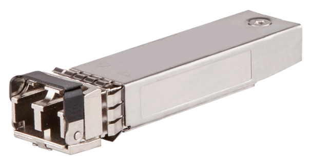
SFP+ modules
SFP+ optical transceiver modules (LC interface)
Figure 39 SFP+ optical transceiver module (LC interface)
Models and specifications
SFP+ optical transceiver modules (LC interface) use an LC connector.
Table 54 Specifications for SFP+ optical transceiver modules (LC interface) (1)
|
Model |
Central wavelength (nm) |
Fiber mode |
Fiber diameter (µm) |
Modal bandwidth (MHz*km) |
Transmission distance |
Data rate |
|
||||||
|
SFP-XG-SX-MM850-A |
850 |
MMF |
50/125 |
4700 |
400 m (1312.34 ft) |
10.31 Gbps |
|
||||||
|
2000 |
300 m (984.25 ft) |
|
|||||||||||
|
500 |
82 m (269.03 ft) |
|
|||||||||||
|
400 |
66 m (216.54 ft) |
|
|||||||||||
|
62.5/125 |
200 |
33 m (108.27 ft) |
|
||||||||||
|
160 |
26 m (85.30 ft) |
|
|||||||||||
|
SFP-XG-SX-MM850-B (end of sale) |
850 |
MMF |
50/125 |
4700 |
400 m (1312.34 ft) |
10.31 Gbps |
|
||||||
|
2000 |
100 m (328.08 ft) |
|
|||||||||||
|
500 |
25 m (82.02 ft) |
|
|||||||||||
|
400 |
20 m (65.62 ft) |
|
|||||||||||
|
62.5/125 |
200 |
10 m (32.81 ft) |
|
||||||||||
|
160 |
8 m (26.25 ft) |
|
|||||||||||
|
SFP-XG-SX-MM850-D |
850 |
MMF |
50/125 |
4700 |
400 m (1312.34 ft) |
10.31 Gbps |
|
||||||
|
2000 |
300 m (984.25 ft) |
|
|||||||||||
|
500 |
82 m (269.03 ft) |
|
|||||||||||
|
400 |
66 m (216.54 ft) |
|
|||||||||||
|
62.5/125 |
200 |
33 m (108.27 ft) |
|
||||||||||
|
160 |
26 m (85.30 ft) |
|
|||||||||||
|
SFP-XG-SX-MM850-H |
850 |
MMF |
50/125 |
4700 |
400 m (1312.34 ft) |
10.31 Gbps |
|
||||||
|
2000 |
300 m (984.25 ft) |
|
|||||||||||
|
500 |
82 m (269.03 ft) |
|
|||||||||||
|
400 |
66 m (216.54 ft) |
|
|||||||||||
|
62.5/125 |
200 |
33 m (108.27 ft) |
|
||||||||||
|
160 |
26 m (85.30 ft) |
|
|||||||||||
|
SFP-XG-SX-MM850-S |
850 |
MMF |
50/125 |
4700 |
400 m (1312.34 ft) |
10.31 Gbps |
|
||||||
|
2000 |
300 m (984.25 ft) |
|
|||||||||||
|
500 |
82 m (269.03 ft) |
|
|||||||||||
|
400 |
66 m (216.54 ft) |
|
|||||||||||
|
62.5/125 |
200 |
33 m (108.27 ft) |
|
||||||||||
|
160 |
26 m (85.30 ft) |
|
|||||||||||
|
SFP-XG-SX-MM850-E |
850 |
MMF |
50/125 |
4700 |
400 m (1312.34 ft) |
10.31 Gbps |
|
||||||
|
2000 |
300 m (984.25 ft) |
|
|||||||||||
|
500 |
82 m (269.03 ft) |
|
|||||||||||
|
400 |
66 m (216.54 ft) |
|
|||||||||||
|
62.5/125 |
200 |
33 m (108.27 ft) |
|
||||||||||
|
160 |
26 m (85.30 ft) |
|
|||||||||||
|
SFP-XG-SX-MM850-F1 (end of sale) |
850 |
MMF |
50/125 |
4700 |
400 m (1312.34 ft) |
10.31 Gbps |
|
||||||
|
2000 |
300 m (984.25 ft) |
|
|||||||||||
|
500 |
82 m (269.03 ft) |
|
|||||||||||
|
400 |
66 m (216.54 ft) |
|
|||||||||||
|
62.5/125 |
200 |
33 m (108.27 ft) |
|
||||||||||
|
160 |
26 m (85.30 ft) |
|
|||||||||||
|
SFP-XG-LX220-MM1310 (end of sale) |
1310 |
MMF |
50/125 |
1500 |
220 m (721.78 ft) |
10.31 Gbps |
|
||||||
|
500 |
220 m (721.78 ft) |
|
|||||||||||
|
400 |
100 m (328.08 ft) |
|
|||||||||||
|
62.5/125 |
200 |
220 m (721.78 ft) |
|
||||||||||
|
160 |
220 m (721.78 ft) |
|
|||||||||||
|
SFP-XG-LX-SM1310 |
1310 |
SMF |
9/125 |
N/A |
10 km (6.21 miles) |
10.31 Gbps |
|
||||||
|
SFP-XG-LX-SM1310-D |
1310 |
SMF |
9/125 |
N/A |
10 km (6.21 miles) |
10.31 Gbps |
|
||||||
|
SFP-XG-LX-SM1310-S |
1310 |
SMF |
9/125 |
N/A |
10 km (6.21 miles) |
10.31 Gbps |
|
||||||
|
SFP-XG-LX-SM1310-CM |
1310 |
SMF |
9/125 |
- |
10 km (6.21 miles) |
10.31 Gbps |
|
||||||
|
SFP-XG-LX-SM1310-E |
1310 |
SMF |
9/125 |
N/A |
10 km (6.21 miles) |
10.31 Gbps |
|
||||||
|
SFP-XG-LH40-SM1550 |
1550 |
SMF |
9/125 |
N/A |
40 km (24.86 miles) |
10.31 Gbps |
|
||||||
|
SFP-XG-LH40-SM1550-D |
1550 |
SMF |
9/125 |
N/A |
40 km (24.86 miles) |
10.31 Gbps |
|
||||||
|
SFP-XG-LH80-SM1550 |
1550 |
SMF |
9/125 |
N/A |
80 km (49.71 miles) |
10.31 Gbps |
|
||||||
|
SFP-XG-LH80-SM1550-D |
1550 |
SMF |
9/125 |
N/A |
80 km (49.71 miles) |
10.31 Gbps |
|
||||||
|
SFP-FC-8G-SW-MM850 |
850 |
MMF |
62.5/125 |
200 |
150 m (492.13 ft) |
2.125 Gbps |
|
||||||
|
70 m (229.66 ft) |
4.25 Gbps |
|
|||||||||||
|
21 m (68.90 ft) |
8.5 Gbps |
|
|||||||||||
|
50/125 |
500 |
300 m (984.25 ft) |
2.125 Gbps |
|
|||||||||
|
150 m (492.13 ft) |
4.25 Gbps |
|
|||||||||||
|
50 m (164.04 ft) |
8.5 Gbps |
|
|||||||||||
|
2000 |
500 m (1640.42 ft) |
2.125 Gbps |
|
||||||||||
|
380 m (1246.72 ft) |
4.25 Gbps |
|
|||||||||||
|
150 m (492.13 ft) |
8.5 Gbps |
|
|||||||||||
|
4700 |
N/A |
2.125 Gbps |
|
||||||||||
|
400 m (1312.34 ft) |
4.25 Gbps |
|
|||||||||||
|
190 m (623.36 ft) |
8.5 Gbps |
|
|||||||||||
|
SFP-FC-8G-SW-MM850-CM |
850 |
MMF |
62.5/125 |
200 |
150 m (492.13 ft) |
2.125 Gbps |
|
||||||
|
70 m (229.66 ft) |
4.25 Gbps |
|
|||||||||||
|
21 m (68.90 ft) |
8.5 Gbps |
|
|||||||||||
|
50/125 |
500 |
300 m (984.25 ft) |
2.125 Gbps |
|
|||||||||
|
150 m (492.13 ft) |
4.25 Gbps |
|
|||||||||||
|
50 m (164.04 ft) |
8.5 Gbps |
|
|||||||||||
|
2000 |
500 m (1640.42 ft) |
2.125 Gbps |
|
||||||||||
|
380 m (1246.72 ft) |
4.25 Gbps |
|
|||||||||||
|
150 m (492.13 ft) |
8.5 Gbps |
|
|||||||||||
|
4700 |
N/A |
2.125 Gbps |
|
||||||||||
|
400 m (1312.34 ft) |
4.25 Gbps |
|
|||||||||||
|
190 m (623.36 ft) |
8.5 Gbps |
|
|||||||||||
|
SFP-FC-8G-LW-SM1310 |
1310 |
SMF |
9/125 |
N/A |
10 km (6.21 miles) |
2.125 Gbps |
|
||||||
|
4.25 Gbps |
|
||||||||||||
|
8.5 Gbps |
|
||||||||||||
|
SFP-FC-16G-SW-MM850 |
850 |
MMF |
62.5/125 |
200 |
70 m (229.66 ft) |
4.25 Gbps |
|||||||
|
21 m (68.90 ft) |
8.5 Gbps |
||||||||||||
|
15 m (49.21 ft) |
14.025 Gbps |
||||||||||||
|
50/125 |
500 |
150 m (492.13 ft) |
4.25 Gbps |
||||||||||
|
50 m (164.04 ft) |
8.5 Gbps |
||||||||||||
|
35 m (114.83 ft) |
14.025 Gbps |
||||||||||||
|
2000 |
380 m (1246.72 ft) |
4.25 Gbps |
|||||||||||
|
150 m (492.13 ft) |
8.5 Gbps |
||||||||||||
|
100 m (328.08 ft) |
14.025 Gbps |
||||||||||||
|
4700 |
400 m (1312.33 ft) |
4.25 Gbps |
|||||||||||
|
190 m (623.36 ft) |
8.5 Gbps |
||||||||||||
|
125 m (410.11 ft) |
14.025 Gbps |
||||||||||||
|
SFP-FC-16G-SW-MM850-CM |
850 |
MMF |
62.5/125 |
200 |
70 m (229.66 ft) |
4.25 Gbps |
|||||||
|
21 m (68.90 ft) |
8.5 Gbps |
||||||||||||
|
15 m (49.21 ft) |
14.025 Gbps |
||||||||||||
|
50/125 |
500 |
150 m (492.13 ft) |
4.25 Gbps |
||||||||||
|
50 m (164.04 ft) |
8.5 Gbps |
||||||||||||
|
35 m (114.83 ft) |
14.025 Gbps |
||||||||||||
|
2000 |
380 m (1246.72 ft) |
4.25 Gbps |
|||||||||||
|
150 m (492.13 ft) |
8.5 Gbps |
||||||||||||
|
100 m (328.08 ft) |
14.025 Gbps |
||||||||||||
|
4700 |
400 m (1312.33 ft) |
4.25 Gbps |
|||||||||||
|
190 m (623.36 ft) |
8.5 Gbps |
||||||||||||
|
125 m (410.11 ft) |
14.025 Gbps |
||||||||||||
|
SFP-FC-16G-LW-SM1310 |
1310 |
SMF |
9/125 |
N/A |
10 km (6.21 miles) |
4.25 Gbps |
|||||||
|
8.5 Gbps |
|||||||||||||
|
14.025 Gbps |
|||||||||||||
|
SFP-FC-16G-LW-SM1310-CM |
1310 |
SMF |
9/125 |
N/A |
10 km (6.21 miles) |
4.25 Gbps |
|||||||
|
8.5 Gbps |
|||||||||||||
|
14.025 Gbps |
|||||||||||||
|
SFP-FC-32G-SW-MM850 |
850 |
MMF |
62.5/125 |
200 |
21 m (68.90 ft) |
8.5 Gbps |
|||||||
|
15 m (49.21 ft) |
14.025 Gbps |
||||||||||||
|
N/A |
28.05 Gbps |
||||||||||||
|
50/125 |
500 |
50 m (164.04 ft) |
8.5 Gbps |
||||||||||
|
35 m (114.83 ft) |
14.025 Gbps |
||||||||||||
|
20 m (65.62 ft) |
28.05 Gbps |
||||||||||||
|
2000 |
150 m (492.13 ft) |
8.5 Gbps |
|||||||||||
|
100 m (328.08 ft) |
14.025 Gbps |
||||||||||||
|
70 m (229.66 ft) |
28.05 Gbps |
||||||||||||
|
4700 |
190 m (623.36 ft) |
8.5 Gbps |
|||||||||||
|
125 m (410.11 ft) |
14.025 Gbps |
||||||||||||
|
100 m (328.08 ft) |
28.05 Gbps |
||||||||||||
|
SFP-FC-32G-SW-MM850-CM |
850 |
MMF |
62.5/125 |
200 |
21 m (68.90 ft) |
8.5 Gbps |
|||||||
|
15 m (49.21 ft) |
14.025 Gbps |
||||||||||||
|
N/A |
28.05 Gbps |
||||||||||||
|
50/125 |
500 |
50 m (164.04 ft) |
8.5 Gbps |
||||||||||
|
35 m (114.83 ft) |
14.025 Gbps |
||||||||||||
|
20 m (65.62 ft) |
28.05 Gbps |
||||||||||||
|
2000 |
150 m (492.13 ft) |
8.5 Gbps |
|||||||||||
|
100 m (328.08 ft) |
14.025 Gbps |
||||||||||||
|
70 m (229.66 ft) |
28.05 Gbps |
||||||||||||
|
4700 |
190 m (623.36 ft) |
8.5 Gbps |
|||||||||||
|
125 m (410.11 ft) |
14.025 Gbps |
||||||||||||
|
100 m (328.08 ft) |
28.05 Gbps |
||||||||||||
|
SFP-XG-LH80-Tunable (end of sale) |
1547.75 |
SMF |
9/125 |
N/A |
80 km (49.71 miles) |
9.95 to 11.3 Gbps |
|
||||||
|
*SFP-XG-CPRI-IR-SM1310 |
1310 |
SMF |
9/125 |
N/A |
1.4 km (0.87 miles) |
4.91 to 10.31 Gbps |
|
||||||
|
*SFP-XG-CPRI-LR-SM1310 |
1310 |
SMF |
9/125 |
N/A |
10 km (6.21 miles) |
4.91 to 10.31 Gbps |
|
||||||
|
SFP-XG-LX-SM1270-BIDI |
Transmitting end (TX): 1270 Receiving end (RX): 1330 |
SMF |
9/125 |
N/A |
10 km (6.21 miles) |
10.31Gbps |
|
||||||
|
SFP-XG-LX-SM1270-BIDI-S |
Transmitting end (TX): 1270 Receiving end (RX): 1330 |
SMF |
9/125 |
N/A |
10 km (6.21 miles) |
10.31Gbps |
|
||||||
|
SFP-XG-LX-SM1330-BIDI |
Transmitting end (TX): 1330 Receiving end (RX): 1270 |
SMF |
9/125 |
N/A |
10 km (6.21 miles) |
10.31Gbps |
|
||||||
|
SFP-XG-LX-SM1330-BIDI-S |
Transmitting end (TX): 1330 Receiving end (RX): 1270 |
SMF |
9/125 |
N/A |
10 km (6.21 miles) |
10.31Gbps |
|
||||||
|
SFP-XG-LH40-SM1270-BIDI |
Transmitting end (TX): 1270 Receiving end (RX): 1330 |
SMF |
9/125 |
N/A |
40 km (24.86 miles) |
10.31Gbps |
|
||||||
|
SFP-XG-LH40-SM1330-BIDI |
Transmitting end (TX): 1330 Receiving end (RX): 1270 |
SMF |
9/125 |
N/A |
40 km (24.86 miles) |
10.31Gbps |
|
||||||
|
SFP-XG-LH80-SM1490-BIDI |
Transmitting end (TX): 1490 Receiving end (RX): 1550 |
SMF |
9/125 |
N/A |
80 km (49.71 miles) |
10.31Gbps |
|
||||||
|
SFP-XG-LH80-SM1550-BIDI |
Transmitting end (TX): 1550 Receiving end (RX): 1490 |
SMF |
9/125 |
N/A |
80 km (49.71 miles) |
10.31Gbps |
|
||||||
|
|
NOTE: · BIDI optical transceiver modules use different central wavelengths in transmit and receive directions, in order to implement bidirectional transmission of optical signals over the same fiber. · You must use the SFP-XG-LX-SM1270-BIDI and SFP-XG-LX-SM1330-BIDI transceiver modules in pairs. |
Table 55 Specifications for SFP+ optical transceiver modules (LC interface) (2)
|
Model |
Optical parameters (dBm) |
|
|
Transmit power |
Receive power |
|
|
SFP-XG-SX-MM850-A |
–7.3 to –1 |
–9.9 to +0.5 |
|
SFP-XG-SX-MM850-B |
–7.3 to –1 |
–9.9 to +0.5 |
|
SFP-XG-SX-MM850-D |
–7.3 to –1 |
–9.9 to +0.5 |
|
SFP-XG-SX-MM850-H |
–7.3 to –1 |
–9.9 to +0.5 |
|
SFP-XG-SX-MM850-S |
–7.3 to –1 |
–9.9 to +0.5 |
|
SFP-XG-SX-MM850-E |
–7.3 to –1 |
–9.9 to +0.5 |
|
SFP-XG-SX-MM850-F1 |
–7.3 to –1 |
–9.9 to +0.5 |
|
SFP-XG-LX220-MM1310 |
–6.5 to +0.5 |
–6.5 to +1.5 |
|
SFP-XG-LX-SM1310 |
–8.2 to +0.5 |
–14.4 to +0.5 |
|
SFP-XG-LX-SM1310-D |
–8.2 to +0.5 |
–14.4 to +0.5 |
|
SFP-XG-LX-SM1310-S |
–8.2 to +0.5 |
–14.4 to +0.5 |
|
SFP-XG-LX-SM1310-CM |
–8.2 to +0.5 |
–14.4 to +0.5 |
|
SFP-XG-LX-SM1310-E |
–8.2 to +0.5 |
–14.4 to +0.5 |
|
SFP-XG-LH40-SM1550 |
–4.7 to +4 |
–15.8 to –1 |
|
SFP-XG-LH40-SM1550-D |
–4.7 to +4 |
–15.8 to –1 |
|
SFP-XG-LH80-SM1550 |
0 to +4 |
–24 to –7 |
|
SFP-XG-LH80-SM1550-D |
0 to +4 |
–24 to –7 |
|
SFP-FC-8G-SW-MM850 |
–10 to 0 (2.125 Gbps) |
–13.1 to 0 (2.125 Gbps) |
|
–9 to 0 (4.25 Gbps) |
–12.1 to 0 (4.25 Gbps) |
|
|
–8.2 to 0 (8.5 Gbps) |
–11.2 to 0 (8.5 Gbps) |
|
|
SFP-FC-8G-LW-SM1310 |
–9.5 to –3 (2.125 Gbps) |
–18.2 to –3 (2.125 Gbps) |
|
–8.4 to –1 (4.25 Gbps) |
–15.4 to –1 (4.25 Gbps) |
|
|
–8.4 to +0.5 (8.5 Gbps) |
–13.8 to +0.5 (8.5 Gbps) |
|
|
SFP-FC-16G-SW-MM850 |
–9 to 0 (4.25 Gbps) |
–12.1 to 0 (4.25 Gbps) |
|
–8.2 to 0 (8.5 Gbps) |
–11.2 to 0 (8.5 Gbps) |
|
|
–7.8 to 0 (14.025 Gbps) |
–10.5 to 0 (14.025 Gbps) |
|
|
SFP-FC-16G-SW-MM850-CM |
–9 to 0 (4.25 Gbps) |
–12.1 to 0 (4.25 Gbps) |
|
–8.2 to 0 (8.5 Gbps) |
–11.2 to 0 (8.5 Gbps) |
|
|
–7.8 to 0 (14.025 Gbps) |
–10.5 to 0 (14.025 Gbps) |
|
|
SFP-FC-16G-LW-SM1310 |
–8.4 to –1 (4.25 Gbps) |
–15.4 to –1 (4.25 Gbps) |
|
–8.4 to +0.5 (8.5 Gbps) |
–13.8 to +0.5 (8.5 Gbps) |
|
|
–5 to +2 (14.025 Gbps) |
–12 to +2 (14.025 Gbps) |
|
|
SFP-FC-16G-LW-SM1310-CM |
–8.4 to –1 (4.25 Gbps) |
–15.4 to –1 (4.25 Gbps) |
|
–8.4 to +0.5 (8.5 Gbps) |
–13.8 to +0.5 (8.5 Gbps) |
|
|
–5 to +2 (14.025 Gbps) |
–12 to +2 (14.025 Gbps) |
|
|
SFP-FC-32G-SW-MM850 |
–8.2 to 0 (8.5 Gbps) |
–11.2 to 0 (8.5 Gbps) |
|
–7.8 to 0 (14.025 Gbps) |
–10.5 to 0 (14.025 Gbps) |
|
|
–6.2 to +2 (28.05 Gbps) |
–10.2 to +2 (28.05 Gbps) |
|
|
SFP-XG-LH80-Tunable |
–1 to +3 |
–24 to –7 |
|
*SFP-XG-CPRI-IR-SM1310 |
–8.2 to +0.5 |
–14.4 to +0.5 |
|
*SFP-XG-CPRI-LR-SM1310 |
–8.2 to +0.5 |
–14.4 to +0.5 |
|
SFP-XG-LX-SM1270-BIDI |
-8.2 to -0.5 |
–14.4 to +0.5 |
|
SFP-XG-LX-SM1270-BIDI-S |
-8.2 to -0.5 |
–14.4 to +0.5 |
|
SFP-XG-LX-SM1330-BIDI |
-8.2 to -0.5 |
–14.4 to +0.5 |
|
SFP-XG-LX-SM1330-BIDI-S |
-8.2 to -0.5 |
–14.4 to +0.5 |
|
SFP-XG-LH40-SM1270-BIDI |
0 to +5 |
–15 to +0.5 |
|
SFP-XG-LH40-SM1330-BIDI |
0 to +5 |
–15 to +0.5 |
|
SFP-XG-LH80-SM1490-BIDI |
0 to +4 |
–23 to –6 |
|
SFP-XG-LH80-SM1550-BIDI |
–1 to +3 |
–23 to –6 |
|
|
NOTE: · A mode conditioning patch cord is required when you use OM1 or OM2 fiber types on an SFP-XG-LX220-MM1310. No mode conditioning patch cords are required for OM3 fiber types. For more information about mode conditioning patch cords, see the IEEE 802.3 standard. · The SFP-XG-LH80-Tunable module supports wavelength adjustment. Cold-starting of the module takes a longer time (usually not exceeding 90 seconds) than other SFP+ modules. |
SFP+ optical transceiver modules (SC interface)
Figure 40 SFP+ optical transceiver module (SC interface)
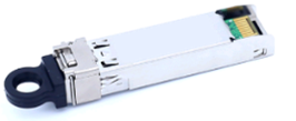
Models and specifications
Table 56 Specifications for SFP+ optical transceiver modules (SC interface) (1)
|
Model |
Central wavelength (nm) |
Fiber mode |
Fiber diameter (µm) |
Transmission distance |
|
SFP-XG-PR30-U-SM1270 |
· Transmitting end (TX): 1270 · Receiving end (RX): 1577.5 |
SMF |
9/125 |
20 km (12.43 miles) |
|
SFP-XG-PRX30-U-SM1310 |
· Transmitting end (TX): 1310 · Receiving end (RX): 1577.5 |
SMF |
9/125 |
20 km (12.43 miles) |
Table 57 Specifications for SFP+ optical transceiver modules (SC interface) (2)
|
Model |
Data rate (Gbps) |
Optical parameters (dBm) |
||
|
Transmitting end (TX) |
Receiving end (RX) |
Transmit power |
Receive power |
|
|
SFP-XG-PR30-U-SM1270 |
10.3125 |
10.3125 |
+4 to +9 |
–10 to –28.5 |
|
SFP-XG-PRX30-U-SM1310 |
1.25 |
10.3125 |
+0.62 to +5.62 |
–10 to –28.5 |
10G EPON OLT SFP+ optical transceiver modules (SC interface)
A 10G EPON OLT SFP+ optical transceiver module uses an SC connector.
Figure 41 10G EPON OLT SFP+ optical transceiver module (SC interface)
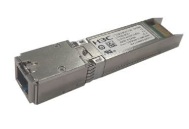
Models and specifications
Table 58 Specifications for 10G EPON OLT SFP+ optical transceiver modules (SC interface) (1)
|
Model |
Central wavelength (nm) |
Fiber mode |
Fiber diameter (µm) |
Transmission distance |
|
SFP-XG-PR30-D-SM1577-A (end of sale) |
· Tx/Rx rate—10.3125 Gbps ¡ Tx: 1577.5 ¡ Rx: 1270 · Tx/Rx rate—1.25 Gbps ¡ Tx: 1490 ¡ Rx: 1310 |
SMF |
9/125 |
20 km (12.43 miles) |
|
SFP-XG-PR30-D-SM1577-C |
· Tx/Rx rate—10.3125 Gbps ¡ Tx: 1577.5 ¡ Rx: 1270 · Tx/Rx rate—1.25 Gbps ¡ Tx: 1490 ¡ Rx: 1310 |
SMF |
9/125 |
20 km (12.43 miles) |
|
SFP-XG-PR40-D-SM1577-A (end of sale) |
· Tx/Rx rate—10.3125 Gbps ¡ Tx: 1577.5 ¡ Rx: 1270 · Tx/Rx rate—1.25 Gbps ¡ Tx: 1490 ¡ Rx: 1310 |
SMF |
9/125 |
20 km (12.43 miles) |
|
SFP-XG-PR40-D-SM1577-C |
· Tx/Rx rate—10.3125 Gbps ¡ Tx: 1577.5 ¡ Rx: 1270 · Tx/Rx rate—1.25 Gbps ¡ Tx: 1490 ¡ Rx: 1310 |
SMF |
9/125 |
20 km (12.43 miles) |
Table 59 Specifications for 10G EPON OLT SFP+ optical transceiver modules (SC interface) (2)
|
Model |
Data rate (Gbps) |
Optical parameters (dBm) |
||
|
Tx |
Rx |
Tx power |
Rx power |
|
|
SFP-XG-PR30-D-SM1577-A |
10.3125 |
10.3125 |
+2 to +5 |
–6 to –28 |
|
1.25 |
1.25 |
+3 to +7 |
–9.38 to –29.78 |
|
|
SFP-XG-PR30-D-SM1577-C |
10.3125 |
10.3125 |
+2 to +5 |
–6 to –28 |
|
1.25 |
1.25 |
+3 to +7 |
–9.38 to –29.78 |
|
|
SFP-XG-PR40-D-SM1577-A |
10.3125 |
10.3125 |
+5 to +9 |
–9 to –29 |
|
1.25 |
1.25 |
+4 to +10 |
–12 to –32 |
|
|
SFP-XG-PR40-D-SM1577-C |
10.3125 |
10.3125 |
+5 to +9 |
–9 to –29 |
|
1.25 |
1.25 |
+4 to +10 |
–12 to –31 |
|
|
|
NOTE: The optical power budget is 29 dBm for the SFP-XG-PR30-D-SM1577-A and SFP-XG-PR30-D-SM1577-C transceiver modules and 33 dBm for the SFP-XG-PR40-D-SM1577-A and SFP-XG-PR40-D-SM1577-C transceiver modules. |
SFP+ copper transceiver modules
Figure 42 SFP+ copper transceiver module
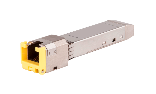
Models and specifications
Table 60 SFP+ copper transceiver module specifications
|
Model |
Transmission distance |
Data rate |
Cable type |
Connector type |
|
SFP-10GE-T |
30 m (98.43 ft) |
10 Gbps |
Category 6a STP or Category 7 STP |
RJ-45 |
|
100 m (328.08 ft) |
1000/100 Mbps |
Category 5e UTP/STP |
|
|
NOTE: Support for data rate autonegotiation of depends on the device model. |
SFP+ copper cables
Figure 43 SFP+ copper cable
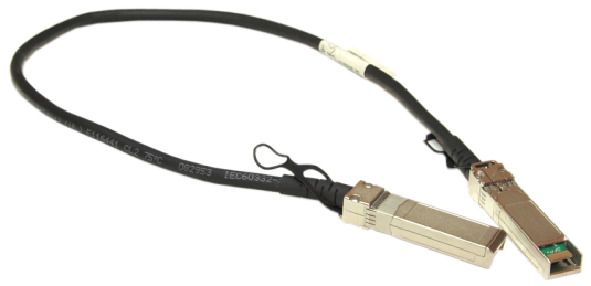
Models and specifications
Table 61 Specifications for SFP+ copper cables
|
Model |
Length |
Data rate |
|
LSWM1STK |
0.65 m (2.13 ft) |
10.31 Gbps |
|
LSWM2STK |
1.2 m (3.94 ft) |
|
|
LSWM3STK |
3 m (9.84 ft) |
|
|
SFP-XG-CAB-3M-CM |
3 m (9.84 ft) |
|
|
LSTM1STK |
5 m (16.40 ft) |
|
|
LSTM1STK-S |
5 m (16.40 ft) |
|
|
SFP-XG-CAB-5M-CM |
5 m (16.40 ft) |
|
|
LSTM2STK |
7 m (22.97 ft) |
SFP+ fiber cables
Figure 44 SFP+ fiber cable
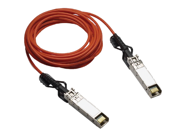
Models and specifications
Table 62 Specifications for SFP+ fiber cables
|
Model |
Length |
Data rate |
|
SFP-XG-D-AOC-7M |
7 m (22.97 ft) |
10.31 Gbps |
|
SFP-XG-D-AOC-7M-H |
7 m (22.97 ft) |
|
|
SFP-XG-D-AOC-10M |
10 m (32.81 ft) |
|
|
SFP-XG-D-AOC-10M-H |
10 m (32.81 ft) |
|
|
SFP-XG-D-AOC-20M |
20 m (65.62 ft) |
|
|
SFP-XG-D-AOC-20M-H |
20 m (65.62 ft) |
XFP modules
XFP optical transceiver modules (LC interface)
Figure 45 XFP optical transceiver module (LC interface)
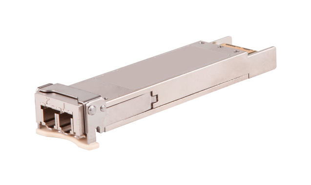
Models and specifications
Table 63 Specifications for XFP optical transceiver modules (LC interface) (1)
|
Model |
Central wavelength (nm) |
Data rate (Gbps) |
Fiber mode |
Fiber diameter (µm) |
Modal bandwidth (MHz*km) |
Transmission distance |
|
|
XFP-SX-MM850 |
850 |
9.95 to 10.31 |
MMF |
50/125 |
4700 |
400 m (1312.34 ft) |
|
|
2000 |
300 m (984.25 ft) |
||||||
|
500 |
82 m (269.03 ft) |
||||||
|
400 |
66 m (216.54 ft) |
||||||
|
62.5/125 |
200 |
33 m (108.27 ft) |
|||||
|
160 |
26 m (85.30 ft) |
||||||
|
XFP-SX-MM850-D |
850 |
9.95 to 10.31 |
MMF |
50/125 |
4700 |
400 m (1312.34 ft) |
|
|
2000 |
300 m (984.25 ft) |
||||||
|
500 |
82 m (269.03 ft) |
||||||
|
400 |
66 m (216.54 ft) |
||||||
|
62.5/125 |
200 |
33 m (108.27 ft) |
|||||
|
160 |
26 m (85.30 ft) |
||||||
|
XFP-LX-SM1310 |
1310 |
9.95 to 10.31 |
SMF |
9/125 |
N/A |
10 km (6.21 miles) |
|
|
XFP-LX-SM1310-D |
1310 |
9.95 to 10.31 |
SMF |
9/125 |
N/A |
10 km (6.21 miles) |
|
|
XFP-POS-LH10-SM1310 |
1310 |
9.95 to 11.3 |
SMF |
9/125 |
N/A |
10 km (6.21 miles) |
|
|
XFP-LH40-SM1550 (end of sale) |
1550 |
9.95 to 10.7 |
SMF |
9/125 |
N/A |
40 km (24.86 miles) |
|
|
XFP-LH40-SM1550-D |
1550 |
9.95 to 10.7 |
SMF |
9/125 |
N/A |
40 km (24.86 miles) |
|
|
XFP-LH40-SM1550-F1 |
1550 |
9.95 to 10.7 |
SMF |
9/125 |
N/A |
40 km (24.86 miles) |
|
|
XFP-LH80-SM1550 |
1550 |
9.95 to 10.31 |
SMF |
9/125 |
N/A |
80 km (49.71 miles) |
|
|
XFP-LH80-SM1550-D |
1550 |
9.95 to 10.31 |
SMF |
9/125 |
N/A |
80 km (49.71 miles) |
|
|
XFP-LX-SM1530.33 (end of sale) |
1530.33 |
9.95 to 10.31 |
SMF |
9/125 |
N/A |
80 km (49.71 miles) |
|
|
XFP-LX-SM1531.12 (end of sale) |
1531.12 |
9.95 to 10.31 |
SMF |
9/125 |
N/A |
80 km (49.71 miles) |
|
|
XFP-LX-SM1531.90 (end of sale) |
1531.90 |
9.95 to 10.31 |
SMF |
9/125 |
N/A |
80 km (49.71 miles) |
|
|
XFP-LX-SM1532.68 (end of sale) |
1532.68 |
9.95 to 10.31 |
SMF |
9/125 |
N/A |
80 km (49.71 miles) |
|
|
XFP-LX-SM1534.25 (end of sale) |
1534.25 |
9.95 to 10.31 |
SMF |
9/125 |
N/A |
80 km (49.71 miles) |
|
|
XFP-LX-SM1535.04 (end of sale) |
1535.04 |
9.95 to 10.31 |
SMF |
9/125 |
N/A |
80 km (49.71 miles) |
|
|
XFP-LX-SM1535.82 (end of sale) |
1535.82 |
9.95 to 10.31 |
SMF |
9/125 |
N/A |
80 km (49.71 miles) |
|
|
XFP-LX-SM1536.61 (end of sale) |
1536.61 |
9.95 to 10.31 |
SMF |
9/125 |
N/A |
80 km (49.71 miles) |
|
|
XFP-LX-SM1538.19 (end of sale) |
1538.19 |
9.95 to 10.31 |
SMF |
9/125 |
N/A |
80 km (49.71 miles) |
|
|
XFP-LX-SM1538.98 (end of sale) |
1538.98 |
9.95 to 10.31 |
SMF |
9/125 |
N/A |
80 km (49.71 miles) |
|
|
XFP-LX-SM1539.77 (end of sale) |
1539.77 |
9.95 to 10.31 |
SMF |
9/125 |
N/A |
80 km (49.71 miles) |
|
|
XFP-LX-SM1540.56 (end of sale) |
1540.56 |
9.95 to 10.31 |
SMF |
9/125 |
N/A |
80 km (49.71 miles) |
|
|
XFP-LX-SM1542.14 (end of sale) |
1542.14 |
9.95 to 10.31 |
SMF |
9/125 |
N/A |
80 km (49.71 miles) |
|
|
XFP-LX-SM1542.94 (end of sale) |
1542.94 |
9.95 to 10.31 |
SMF |
9/125 |
N/A |
80 km (49.71 miles) |
|
|
XFP-LX-SM1543.73 (end of sale) |
1543.73 |
9.95 to 10.31 |
SMF |
9/125 |
N/A |
80 km (49.71 miles) |
|
|
XFP-LX-SM1544.53 (end of sale) |
1544.53 |
9.95 to 10.31 |
SMF |
9/125 |
N/A |
80 km (49.71 miles) |
|
|
XFP-LX-SM1546.12 (end of sale) |
1546.12 |
9.95 to 10.31 |
SMF |
9/125 |
N/A |
80 km (49.71 miles) |
|
|
XFP-LX-SM1546.92 (end of sale) |
1546.92 |
9.95 to 10.31 |
SMF |
9/125 |
N/A |
80 km (49.71 miles) |
|
|
XFP-LX-SM1547.72 (end of sale) |
1547.72 |
9.95 to 10.31 |
SMF |
9/125 |
N/A |
80 km (49.71 miles) |
|
|
XFP-LX-SM1548.51 (end of sale) |
1548.51 |
9.95 to 10.31 |
SMF |
9/125 |
N/A |
80 km (49.71 miles) |
|
|
XFP-LX-SM1550.12 (end of sale) |
1550.12 |
9.95 to 10.31 |
SMF |
9/125 |
N/A |
80 km (49.71 miles) |
|
|
XFP-LX-SM1550.92 (end of sale) |
1550.92 |
9.95 to 10.31 |
SMF |
9/125 |
N/A |
80 km (49.71 miles) |
|
|
XFP-LX-SM1551.72 (end of sale) |
1551.72 |
9.95 to 10.31 |
SMF |
9/125 |
N/A |
80 km (49.71 miles) |
|
|
XFP-LX-SM1552.52 (end of sale) |
1552.52 |
9.95 to 10.31 |
SMF |
9/125 |
N/A |
80 km (49.71 miles) |
|
|
XFP-LX-SM1554.13 (end of sale) |
1554.13 |
9.95 to 10.31 |
SMF |
9/125 |
N/A |
80 km (49.71 miles) |
|
|
XFP-LX-SM1554.94 (end of sale) |
1554.94 |
9.95 to 10.31 |
SMF |
9/125 |
N/A |
80 km (49.71 miles) |
|
|
XFP-LX-SM1555.75 (end of sale) |
1555.75 |
9.95 to 10.31 |
SMF |
9/125 |
N/A |
80 km (49.71 miles) |
|
|
XFP-LX-SM1556.55 (end of sale) |
1556.55 |
9.95 to 10.31 |
SMF |
9/125 |
N/A |
80 km (49.71 miles) |
|
|
XFP-LX-SM1558.17 (end of sale) |
1558.17 |
9.95 to 10.31 |
SMF |
9/125 |
N/A |
80 km (49.71 miles) |
|
|
XFP-LX-SM1558.98 (end of sale) |
1558.98 |
9.95 to 10.31 |
SMF |
9/125 |
N/A |
80 km (49.71 miles) |
|
|
XFP-LX-SM1559.79 (end of sale) |
1559.79 |
9.95 to 10.31 |
SMF |
9/125 |
N/A |
80 km (49.71 miles) |
|
|
XFP-LX-SM1560.61 (end of sale) |
1560.61 |
9.95 to 10.31 |
SMF |
9/125 |
N/A |
80 km (49.71 miles) |
Table 64 Specifications for XFP optical transceiver modules (LC interface) (2)
|
Model |
Optical parameters (dBm) |
|
|
Transmit power |
Receive power |
|
|
XFP-SX-MM850 |
–7.3 to –1.08 |
–9.9 to –1 |
|
XFP-SX-MM850-D |
–7.3 to –1.08 |
–9.9 to –1 |
|
XFP-LX-SM1310 |
–8.2 to +0.5 |
–14.4 to +0.5 |
|
XFP-LX-SM1310-D |
–8.2 to +0.5 |
–14.4 to +0.5 |
|
XFP-POS-LH10-SM1310 |
–6 to –1 |
–10.3 to +0.5 |
|
XFP-LH40-SM1550 |
–1 to +2 |
–14 to –1 |
|
XFP-LH40-SM1550-D |
–1 to +2 |
–14 to –1 |
|
XFP-LH40-SM1550-F1 |
–1 to +2 |
–14.1 to –1 |
|
XFP-LH80-SM1550 |
0 to +4 |
–24 to –7 |
|
XFP-LH80-SM1550-D |
0 to +4 |
–24 to –7 |
|
XFP-LX-SM1530.33 |
–1 to +3 |
–24 to –7 |
|
XFP-LX-SM1531.12 |
–1 to +3 |
–24 to –7 |
|
XFP-LX-SM1531.90 |
–1 to +3 |
–24 to –7 |
|
XFP-LX-SM1532.68 |
–1 to +3 |
–24 to –7 |
|
XFP-LX-SM1534.25 |
–1 to +3 |
–24 to –7 |
|
XFP-LX-SM1535.04 |
–1 to +3 |
–24 to –7 |
|
XFP-LX-SM1535.82 |
–1 to +3 |
–24 to –7 |
|
XFP-LX-SM1536.61 |
–1 to +3 |
–24 to –7 |
|
XFP-LX-SM1538.19 |
–1 to +3 |
–24 to –7 |
|
XFP-LX-SM1538.98 |
–1 to +3 |
–24 to –7 |
|
XFP-LX-SM1539.77 |
–1 to +3 |
–24 to –7 |
|
XFP-LX-SM1540.56 |
–1 to +3 |
–24 to –7 |
|
XFP-LX-SM1542.14 |
–1 to +3 |
–24 to –7 |
|
XFP-LX-SM1542.94 |
–1 to +3 |
–24 to –7 |
|
XFP-LX-SM1543.73 |
–1 to +3 |
–24 to –7 |
|
XFP-LX-SM1544.53 |
–1 to +3 |
–24 to –7 |
|
XFP-LX-SM1546.12 |
–1 to +3 |
–24 to –7 |
|
XFP-LX-SM1546.92 |
–1 to +3 |
–24 to –7 |
|
XFP-LX-SM1547.72 |
–1 to +3 |
–24 to –7 |
|
XFP-LX-SM1548.51 |
–1 to +3 |
–24 to –7 |
|
XFP-LX-SM1550.12 |
–1 to +3 |
–24 to –7 |
|
XFP-LX-SM1550.92 |
–1 to +3 |
–24 to –7 |
|
XFP-LX-SM1551.72 |
–1 to +3 |
–24 to –7 |
|
XFP-LX-SM1552.52 |
–1 to +3 |
–24 to –7 |
|
XFP-LX-SM1554.13 |
–1 to +3 |
–24 to –7 |
|
XFP-LX-SM1554.94 |
–1 to +3 |
–24 to –7 |
|
XFP-LX-SM1555.75 |
–1 to +3 |
–24 to –7 |
|
XFP-LX-SM1556.55 |
–1 to +3 |
–24 to –7 |
|
XFP-LX-SM1558.17 |
–1 to +3 |
–24 to –7 |
|
XFP-LX-SM1558.98 |
–1 to +3 |
–24 to –7 |
|
XFP-LX-SM1559.79 |
–1 to +3 |
–24 to –7 |
|
XFP-LX-SM1560.61 |
–1 to +3 |
–24 to –7 |
10G EPON OLT XFP optical transceiver modules (SC interface)
Figure 46 10G EPON OLT XFP optical transceiver module (SC interface)
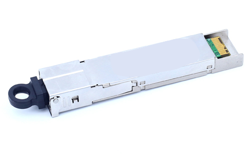
Models and specifications
Table 65 Specifications for 10G EPON OLT XFP optical transceiver modules (SC interface) (1)
|
Model |
Central wavelength (nm) |
Fiber mode |
Fiber diameter (µm) |
Transmission distance |
|
|
XFP-PR30-D-SM1577 |
· Data rate of 10.3125 Gbps at both the transmitting end (TX) and receiving end (RX) ¡ TX: 1577.5 ¡ RX: 1270 · Data rate of 1.25 Gbps at both the TX and RX ¡ TX: 1490 ¡ RX: 1310 |
SMF |
9/125 |
20 km (12.43 miles) |
|
|
XFP-PRX30-D-SM1577 |
· Data rate of 10.3125 Gbps at the TX and 1.25 Gbps at the RX ¡ TX: 1577.5 ¡ RX: 1310 · Data rate of 1.25 Gbps at both the TX and RX ¡ TX: 1490 ¡ RX: 1310 |
SMF |
9/125 |
20 km (12.43 miles) |
Table 66 Specifications for 10G EPON OLT XFP optical transceiver modules (SC interface) (2)
|
Model |
Data rate (Gbps) |
Optical parameters (dBm) |
||
|
Transmitting end (TX) |
Receiving end (RX) |
Transmit power |
Receive power |
|
|
XFP-PR30-D-SM1577 |
10.3125 |
10.3125 |
+2 to +5 |
–6 to –28 |
|
1.25 |
1.25 |
+3 to +7 |
–9.38 to –29.8 |
|
|
XFP-PRX30-D-SM1577 |
10.3125 |
1.25 |
+2 to +5 |
–9.38 to –29.8 |
|
1.25 |
+3 to +7 |
|||
|
|
NOTE: To accurately measure the optical power of 10G EPON OLT or ONU ports, use an optical power meter specially designed for 10G EPON, for example VIAVI OLP-87 used by H3C, |
CX4 cables
Figure 47 CX4 cable
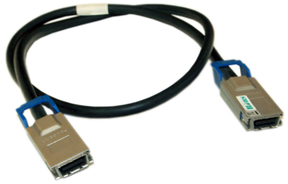
Models and specifications
Table 67 Specifications for CX4 cables
|
Model |
Length |
Data rate |
Type |
|
LSPM2STKA |
0.5 m (1.64 ft) |
12 Gbps |
CX4 cable |
|
LSPM2STKB |
1 m (3.28 ft) |
||
|
LSPM2STKC |
3 m (9.84 ft) |
SFP modules
2.5-Gigabit SFP optical transceiver modules
Figure 48 2.5-Gigabit/Gigabit/622-Megabit/100-Megabit SFP optical transceiver module
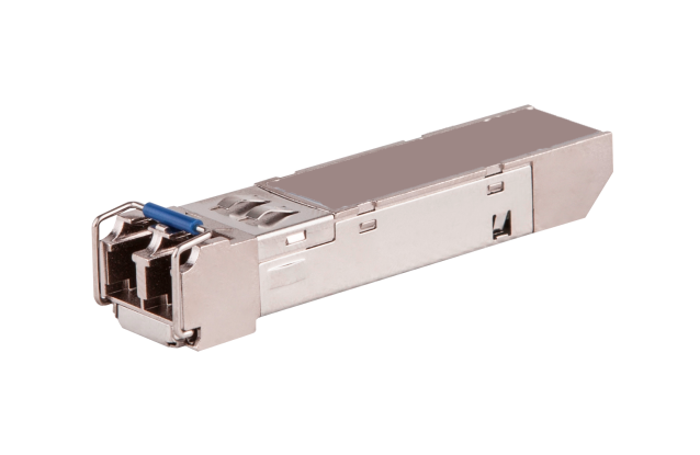
Models and specifications
2.5-Gigabit SFP optical transceiver modules use an LC connector.
Table 68 Specifications for 2.5-Gigabit SFP optical transceiver modules (1)
|
Model |
Central wavelength (nm) |
Fiber mode |
Fiber diameter (μm) |
Transmission distance |
|
SFP-2.5G-LX-SM1310 |
1310 |
SMF |
9/125 |
2 km (1.24 miles) |
|
*SFP-2.5G-LX10-SM1310-DR-I |
1310 |
SMF |
9/125 |
10 km (6.21 miles) |
|
SFP-2.5G-LH15-SM1310 |
1310 |
SMF |
9/125 |
15 km (9.32 miles) |
|
SFP-2.5G-LH40-SM1310 (end of sale) |
1310 |
SMF |
9/125 |
40 km (24.86 miles) |
|
SFP-2.5G-LH80-SM1550 (end of sale) |
1550 |
SMF |
9/125 |
80 km (49.71 miles) |
Table 69 Specifications for 2.5-Gigabit SFP optical transceiver modules (2)
|
Model |
Optical parameters (dBm) |
|
|
Transmit power |
Receive power |
|
|
SFP-2.5G-LX-SM1310 |
–10 to –3 |
–18 to –3 |
|
*SFP-2.5G-LX10-SM1310-DR-I |
–5 to –0.5 |
–14.4 to –0.5 |
|
SFP-2.5G-LH15-SM1310 |
–5 to 0 |
–18 to 0 |
|
SFP-2.5G-LH40-SM1310 |
–2 to +3 |
–27 to –9 |
|
SFP-2.5G-LH80-SM1550 |
–20 to –14 |
–31 to –12 |
SFP GPON ONU optical transceiver modules (SC interface)
Figure 49 SFP GPON ONU optical transceiver module
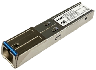
Models and specifications
Gigabit GPON ONU optical transceiver modules provide a transmission rate of 1250 Mbps and use an SC connector.
Table 70 Specifications for SFP GPON ONU optical transceiver modules (1)
|
Model |
Central wavelength (nm) |
Fiber mode |
Fiber diameter (μm) |
Transmission distance |
|
*SFP-GPON-ONU-STICK-BP-SM1310-I |
TX: 1310 RX: 1490 |
SMF |
9/125 |
20 km (12.43 miles) |
Table 71 Specifications for SFP GPON ONU optical transceiver modules (2)
|
Model |
Transmission rate (Gbps) |
Optical parameters (dBm) |
||
|
Tx |
Rx |
Transmit power |
Receive power |
|
|
*SFP-GPON-ONU-STICK-BP-SM1310-I |
1.25 |
2.5 |
+0.5 to +5 |
–27 to –8 |
|
|
IMPORTANT: · The SFP-GPON-ONU-STICK-BP-SM1310-I is a Class B+ GPON ONU optical transceiver module. As a best practice, use it in pair with a Class B+ GPON OLT transceiver module. · The optical power budget for the SFP-GPON-ONU-STICK-BP-SM1310-I transceiver module is 28 dBm. |
SFP GPON OLT optical transceiver modules (SC interface)
Figure 50 SFP GPON OLT optical transceiver module
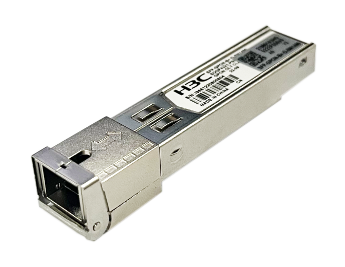
Models and specifications
Gigabit GPON OLT optical transceiver modules provide a transmission rate of 1250 Mbps and use an SC connector.
Table 72 Specifications for SFP GPON OLT optical transceiver modules (1)
|
Model |
Central wavelength (nm) |
Fiber mode |
Fiber diameter (μm) |
Transmission distance |
|
SFP-GPON-ONU-STICK-BP-SM1310-I |
TX: 1490 RX: 1310 |
SMF |
9/125 |
20 km (12.43 miles) |
|
SFP-GPON-C+-D-SM1490 |
TX: 1490 RX: 1310 |
SMF |
9/125 |
20 km (12.43 miles) |
|
SFP-GPON-C++-D-SM1490 |
TX: 1490 RX: 1310 |
SMF |
9/125 |
20 km (12.43 miles) |
Table 73 Specifications for SFP GPON OLT optical transceiver modules (2)
|
Model |
Transmission rate (Gbps) |
Optical parameters (dBm) |
||
|
Tx |
Rx |
Transmit power |
Receive power |
|
|
SFP-GPON-B+-D-SM1490 |
2.5 |
1.25 |
+1.5 to +5 |
–8 to –28 |
|
SFP-GPON-C+-D-SM1490 |
2.5 |
1.25 |
+3 to +7 |
–12 to –30 |
|
SFP-GPON-C++-D-SM1490 |
2.5 |
1.25 |
+6 to +10 |
–12 to –33 |
|
|
IMPORTANT: · The SFP-GPON-B+-D-SM1490 is a Class B+ GPON OLT optical transceiver module. As a best practice, use it in pair with a Class B+ GPON ONU transceiver module. · The SFP-GPON-C+-D-SM1490 is a Class C+ GPON OLT optical transceiver module. · The SFP-GPON-C++-D-SM1490 is a Class C++ GPON OLT optical transceiver module. · The optical power budget for an SFP-GPON-B+-D-SM1490 transceiver is 28 dBm. · The optical power budget for an SFP-GPON-C+-D-SM1490 transceiver is 32 dBm. · The optical power budget for an SFP-GPON-C++-D-SM1490 transceiver is 33 dBm. |
Gigabit SFP optical transceiver modules
See Figure 48 for a view of the Gigabit SFP optical transceiver module.
Models and specifications
Gigabit SFP optical transceiver modules provide a transmission rate of 1250 Mbps and use a dual LC connector.
Table 74 Specifications for Gigabit SFP optical transceiver modules (1)
|
Model |
Central wavelength (nm) |
Fiber mode |
Fiber diameter (μm) |
Modal bandwidth at 850 nm (MHz*km) |
Transmission distance |
|
SFP-GE-SX-MM850-A |
850 |
MMF |
50/125 |
500 |
550 m (1804.46 ft) |
|
400 |
500 m (1640.42 ft) |
||||
|
62.5/125 |
200 |
275 m (902.23 ft) |
|||
|
160 |
220 m (721.78 ft) |
||||
|
SFP-GE-SX-MM850-CM |
850 |
MMF |
50/125 |
500 |
550 m (1804.46 ft) |
|
400 |
500 m (1640.42 ft) |
||||
|
62.5/125 |
200 |
275 m (902.23 ft) |
|||
|
160 |
220 m (721.78 ft) |
||||
|
SFP-GE-SX-MM850-D |
850 |
MMF |
50/125 |
500 |
550 m (1804.46 ft) |
|
400 |
500 m (1640.42 ft) |
||||
|
62.5/125 |
200 |
275 m (902.23 ft) |
|||
|
160 |
220 m (721.78 ft) |
||||
|
SFP-GE-SX-MM850-S |
850 |
MMF |
50/125 |
500 |
550 m (1804.46 ft) |
|
400 |
500 m (1640.42 ft) |
||||
|
62.5/125 |
200 |
275 m (902.23 ft) |
|||
|
160 |
220 m (721.78 ft) |
||||
|
SFP-GE-LX-SM1310-A |
1310 |
SMF |
9/125 |
N/A |
10 km (6.21 miles) |
|
MMF |
50/125 |
500 or 400 |
550 m (1804.46 ft) |
||
|
62.5/125 |
500 |
550 m (1804.46 ft) |
|||
|
SFP-GE-LX-SM1310-C |
1310 |
SMF |
9/125 |
N/A |
10 km (6.21 miles) |
|
SFP-GE-LX-SM1310-D |
1310 |
SMF |
9/125 |
N/A |
10 km (6.21 miles) |
|
SFP-GE-LX-SM1310-S |
1310 |
SMF |
9/125 |
N/A |
10 km (6.21 miles) |
|
*SFP-GE-LX10-SM1310 |
1310 |
SMF |
9/125 |
N/A |
10 km (6.21 miles) |
|
SFP-GE/FE-LX10-SM1310 |
1310 |
SMF |
9/125 |
N/A |
10 km (6.21 miles) |
|
*SFP-GE-LH20-SM1310-I |
1310 |
SMF |
9/125 |
N/A |
20 km (12.43 miles) |
|
*SFP-GE-LH40-SM1310-I |
1310 |
SMF |
9/125 |
N/A |
40 km (24.86 miles) |
|
SFP-GE-LH40-SM1310 |
1310 |
SMF |
9/125 |
N/A |
40 km (24.86 miles) |
|
SFP-GE-LH40-SM1310-D |
1310 |
SMF |
9/125 |
N/A |
40 km (24.86 miles) |
|
SFP-GE-LH40-SM1310-S |
1310 |
SMF |
9/125 |
N/A |
40 km (24.86 miles) |
|
SFP-GE-LH40-SM1550 |
1550 |
SMF |
9/125 |
N/A |
40 km (24.86 miles) |
|
SFP-GE-LH40-SM1550-S |
1550 |
SMF |
9/125 |
N/A |
40 km (24.86 miles) |
|
SFP-GE-LH80-SM1550 |
1550 |
SMF |
9/125 |
N/A |
80 km (49.71 miles) |
|
SFP-GE-LH80-SM1550-D |
1550 |
SMF |
9/125 |
N/A |
80 km (49.71 miles) |
|
SFP-GE-LH100-SM1550 |
1550 |
SMF |
9/125 |
N/A |
100 km (62.14 miles) |
Table 75 Specifications for Gigabit SFP optical transceiver modules (2)
|
Model |
Optical parameters (dBm) |
|
|
Transmit power |
Receive power |
|
|
SFP-GE-SX-MM850-A |
–9.5 to 0 |
–17 to –3 |
|
SFP-GE-SX-MM850-CM |
-9.5 to 0 |
-17 to –3 |
|
SFP-GE-SX-MM850-D |
–9.5 to 0 |
–17 to –3 |
|
SFP-GE-SX-MM850-S |
–9.5 to 0 |
–17 to –3 |
|
SFP-GE-LX-SM1310-A |
–9.5 to –3 |
–20 to –3 |
|
SFP-GE-LX-SM1310-C |
–9.5 to –3 |
–20 to –3 |
|
SFP-GE-LX-SM1310-D |
–9.5 to –3 |
–20 to –3 |
|
SFP-GE-LX-SM1310-S |
–9.5 to –3 |
–20 to –3 |
|
*SFP-GE-LX10-SM1310 |
–11 to –3 |
–19 to –3 |
|
SFP-GE/FE-LX10-SM1310 |
–9.5 to –3 |
–22 to –3 |
|
*SFP-GE-LH20-SM1310-I |
–8 to –3 |
–23 to –3 |
|
*SFP-GE-LH40-SM1310-I |
–5 to 0 |
–23 to –3 |
|
SFP-GE-LH40-SM1310 |
–5 to +5 |
–22 to –3 |
|
SFP-GE-LH40-SM1310-D |
–5 to +5 |
–22 to –3 |
|
SFP-GE-LH40-SM1310-S |
–5 to +5 |
–22 to –3 |
|
SFP-GE-LH40-SM1550 |
–4 to +1 |
–21 to –3 |
|
SFP-GE-LH40-SM1550-S |
–4 to +1 |
–21 to –3 |
|
SFP-GE-LH80-SM1550 |
–4 to +5 |
–22 to –3 |
|
SFP-GE-LH80-SM1550-D |
–4 to +5 |
–22 to –3 |
|
SFP-GE-LH100-SM1550 |
0 to +5 |
–30 to –9 |
|
|
NOTE: The transmission distance of the SFP-GE-LH80-SM1550 and SFP-GE-LH80-SM1550-D transceiver modules might be displayed as 70 km (43.50 miles) on H3C devices with old software versions. Devices with upgraded software versions can correctly display the distance. The actual transmission distance is 80 km (49.71 miles). |
622-Megabit SFP optical transceiver modules
See Figure 48 for a view of the 622-Megabit SFP optical transceiver module.
Models and specifications
622-Megabit SFP optical transceiver modules use a dual LC connector.
Table 76 Specifications for 622-Megabit SFP optical transceiver modules (1)
|
Model |
Central wavelength (nm) |
Fiber mode |
Fiber diameter (μm) |
Transmission distance |
|
SFP-622M-LX-SM1310 |
1310 |
SMF |
9/125 |
15 km (9.32 miles) |
|
SFP-622M-LH40-SM1310 |
1310 |
SMF |
9/125 |
40 km (24.86 miles) |
|
SFP-622M-LH80-SM1550 |
1550 |
SMF |
9/125 |
80 km (49.71 miles) |
Table 77 Specifications for 622-Megabit SFP optical transceiver modules (2)
|
Model |
Optical parameters (dBm) |
|
|
Transmit power |
Receive power |
|
|
SFP-622M-LX-SM1310 |
–15 to –8 |
–28 to –8 |
|
SFP-622M-LH40-SM1310 |
–3 to +2 |
–28 to –8 |
|
SFP-622M-LH80-SM1550 |
–3 to +2 |
–28 to –8 |
100-Megabit SFP optical transceiver modules
See Figure 48 for a view of the 100-Megabit SFP optical transceiver module.
Models and specifications
100-Megabit SFP optical transceiver modules provide a maximum transmission rate of 155 Mbps and use a dual LC connector.
Table 78 Specifications for 100-Megabit SFP optical transceiver modules (1)
|
Model |
Central wavelength (nm) |
Fiber mode |
Fiber diameter (μm) |
Transmission distance |
|
SFP-FE-SX-MM1310-A |
1310 |
MMF |
50/125 |
2 km (1.24 miles) |
|
62.5/125 |
||||
|
SFP-FE-SX-MM1310-GE (end of sale) |
1310 |
MMF |
50/125 |
2 km (1.24 miles) |
|
62.5/125 |
||||
|
SFP-GE/FE-LX10-SM1310 |
1310 |
SMF |
9/125 |
10 km (6.21 miles) |
|
SFP-FE-LX-SM1310-A |
1310 |
SMF |
9/125 |
15 km (9.32 miles) |
|
SFP-FE-LX-SM1310-D |
1310 |
SMF |
9/125 |
15 km (9.32 miles) |
|
*SFP-FE-BX15-U-SM1310 |
1310 |
SMF |
9/125 |
15 km (9.32 miles) |
|
SFP-FE-LH40-SM1310 |
1310 |
SMF |
9/125 |
40 km (24.86 miles) |
|
SFP-FE-LH80-SM1550 |
1550 |
SMF |
9/125 |
80 km (49.71 miles) |
Table 79 Specifications for 100-Megabit SFP optical transceiver modules (2)
|
Model |
Optical parameters (dBm) |
|
|
Transmit power |
Receive power |
|
|
SFP-FE-SX-MM1310-A |
–19 to –14 |
–30 to –14 |
|
SFP-FE-SX-MM1310-GE |
–20 to –14 |
–31.5 to –8 |
|
SFP-GE/FE-LX10-SM1310 |
–15 to –8 |
–28 to –8 |
|
SFP-FE-LX-SM1310-A |
–15 to –8 |
–28 to –7 |
|
SFP-FE-LX-SM1310-D |
–15 to –8 |
–28 to –7 |
|
*SFP-FE-BX15-U-SM1310 |
–15 to –8 |
–28 to –8 |
|
SFP-FE-LH40-SM1310 |
–5 to 0 |
–34 to –9 |
|
SFP-FE-LH80-SM1550 |
–5 to 0 |
–34 to –10 |
Gigabit BIDI optical transceiver modules
Figure 51 Gigabit/100-Megabit BIDI optical transceiver module

Models and specifications
Gigabit BIDI optical transceiver modules provide a transmission rate of 1250 Mbps and use a dual LC connector.
Table 80 Specifications for Gigabit BIDI optical transceiver modules (1)
|
Model |
Central wavelength (nm) |
Fiber mode |
Fiber diameter (μm) |
Transmission distance |
|
SFP-GE-LX-SM1310-BIDI |
· Transmitting end (TX): 1310 · Receiving end (RX): 1490 |
SMF |
9/125 |
10 km (6.21 miles) |
|
SFP-GE-LX-SM1310-BIDI-S |
· Transmitting end (TX): 1310 · Receiving end (RX): 1490 |
SMF |
9/125 |
10 km (6.21 miles) |
|
*SFP-GE-LX-SM1310-BIDI-I |
· Transmitting end (TX): 1310 · Receiving end (RX): 1490 |
SMF |
9/125 |
10 km (6.21 miles) |
|
SFP-GE-LX-SM1490-BIDI |
· Transmitting end (TX): 1490 · Receiving end (RX): 1310 |
SMF |
9/125 |
10 km (6.21 miles) |
|
SFP-GE-LX-SM1490-BIDI-S |
· Transmitting end (TX): 1490 · Receiving end (RX): 1310 |
SMF |
9/125 |
10 km (6.21 miles) |
|
*SFP-GE-LX-SM1490-BIDI-I |
· Transmitting end (TX): 1490 · Receiving end (RX): 1310 |
SMF |
9/125 |
10 km (6.21 miles) |
|
SFP-GE-LH40-SM1310-BIDI |
· Transmitting end (TX): 1310 · Receiving end (RX): 1550 |
SMF |
9/125 |
40 km (24.86 miles) |
|
SFP-GE-LH40-SM1550-BIDI |
· Transmitting end (TX): 1550 · Receiving end (RX): 1310 |
SMF |
9/125 |
40 km (24.86 miles) |
|
SFP-GE-LH70-SM1490-BIDI |
· Transmitting end (TX): 1490 · Receiving end (RX): 1550 |
SMF |
9/125 |
70 km (43.50 miles) |
|
SFP-GE-LH70-SM1550-BIDI |
· Transmitting end (TX): 1550 · Receiving end (RX): 1490 |
SMF |
9/125 |
70 km (43.50 miles) |
Table 81 Specifications for Gigabit BIDI optical transceiver modules (2)
|
Model |
Optical parameters (dBm) |
|
|
Transmit power |
Receive power |
|
|
SFP-GE-LX-SM1310-BIDI |
–9 to –3 |
–18.7 to –3 |
|
SFP-GE-LX-SM1310-BIDI-S |
||
|
SFP-GE-LX-SM1490-BIDI |
||
|
SFP-GE-LX-SM1490-BIDI-S |
||
|
*SFP-GE-LX-SM1310-BIDI-I |
–9 to –3 |
–20 to –3 |
|
*SFP-GE-LX-SM1490-BIDI-I |
||
|
SFP-GE-LH40-SM1310-BIDI |
–5 to 0 |
–23 to –3 |
|
SFP-GE-LH40-SM1550-BIDI |
||
|
SFP-GE-LH70-SM1490-BIDI |
–3 to +5 |
–23 to –3 |
|
SFP-GE-LH70-SM1550-BIDI |
||
|
|
NOTE: · BIDI optical transceiver modules use different central wavelengths in transmit and receive directions, in order to implement bidirectional transmission of optical signals over the same fiber. · You must use the SFP-GE-LX-SM1310-BIDI and SFP-GE-LX-SM1490-BIDI transceiver modules in pairs. |
100-Megabit BIDI optical transceiver modules
See Figure 51 for a view of the 100-Megabit BIDI optical transceiver module.
Models and specifications
100-Megabit BIDI optical transceiver modules provide a transmission rate of 155 Mbps and use a dual LC connector.
Table 82 Specifications for 100-Megabit BIDI optical transceiver modules (1)
|
Model |
Central wavelength (nm) |
Fiber mode |
Fiber diameter (μm) |
Transmission distance |
|
SFP-FE-LX-SM1310-BIDI |
· Transmitting end (TX): 1310 · Receiving end (RX): 1550 |
SMF |
9/125 |
15 km (9.32 miles) |
|
SFP-FE-LX-SM1550-BIDI |
· Transmitting end (TX): 1550 · Receiving end (RX): 1310 |
SMF |
9/125 |
15 km (9.32 miles) |
Table 83 Specifications for 100-Megabit BIDI optical transceiver modules (2)
|
Model |
Optical parameters (dBm) |
|
|
Transmit power |
Receive power |
|
|
SFP-FE-LX-SM1310-BIDI |
–15 to –8 |
–31 to –3 |
|
SFP-FE-LX-SM1550-BIDI |
||
|
|
NOTE: · BIDI optical transceiver modules use different central wavelengths in transmit and receive directions, in order to implement bidirectional transmission of optical signals over the same fiber. · You must use the SFP-FE-LX-SM1310-BIDI and SFP-FE-LX-SM1550-BIDI transceiver modules in pairs. |
BIDI GEPON OLT optical transceiver modules (SC interface)
Figure 52 BIDI GEPON OLT optical transceiver module
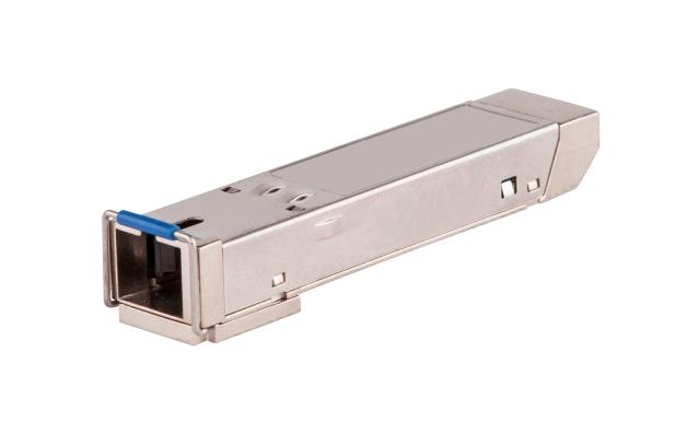
Models and specifications
BIDI GEPON OLT optical transceiver modules provide a transmission rate of 1250 Mbps and use an SC connector.
Table 84 Specifications for BIDI GEPON OLT optical transceiver modules (1)
|
External model |
Central wavelength (nm) |
Fiber mode |
Fiber diameter (µm) |
Transmission distance |
|
SFP-GE-PX10-D-SM1490-A (end of sale) |
· Transmitting end (TX): 1490 · Receiving end (RX): 1310 |
SMF |
9/125 |
10 km (6.21 miles) |
|
SFP-GE-PX20-D-SM1490-A (end of sale) |
· Transmitting end (TX): 1490 · Receiving end (RX): 1310 |
SMF |
9/125 |
20 km (12.43 miles) |
|
SFP-GE-PX20-D-SM1490-M |
· Transmitting end (TX): 1490 · Receiving end (RX): 1310 |
SMF |
9/125 |
20 km (12.43 miles) |
Table 85 Specifications for BIDI GEPON OLT optical transceiver modules (2)
|
External model |
Connector index (dBm) |
||
|
Output fiber power |
Receiving sensitivity |
Fiber saturation |
|
|
SFP-GE-PX10-D-SM1490-A |
–3 to +2 |
≤ –24 |
≤ –3 |
|
SFP-GE-PX20-D-SM1490-A |
+2 to +7 |
≤ –30 |
≤ –10 |
|
SFP-GE-PX20-D-SM1490-M |
+2 to +7 |
≤ –28 |
≤ –6 |
|
|
NOTE: · BIDI GEPON OLT optical transceiver module is a kind of Gigabit SFP module specially used for EPON OLT end devices. The fiber signals transmitted through SFP-GE-PX10-D-SM1490-A module can be used for only the ONU devices with a transmission distance of 10 km (6.2 miles). · When testing the fiber power of EPON OLT and ONU ports, please use the fiber power meter dedicated for EPON (the fiber power meter model used in H3C is JDSU OLP-57) to ensure the correctness of the test result. |
Gigabit CWDM optical transceiver modules (LC interface)
Figure 53 Gigabit CWDM optical transceiver module
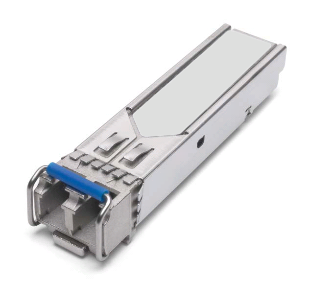
Models and specifications
Gigabit CWDM optical transceiver modules provide a transmission rate of 1250 Mbps and use a dual LC connector.
Table 86 Specifications for Gigabit CWDM optical transceiver modules (1)
|
Model |
Central wavelength (nm) |
Fiber mode |
Fiber diameter (µm) |
Transmission distance |
|
SFP-GE-LH70-SM1470-CW (end of sale) |
1470 |
SMF |
9/125 |
70 km (43.50 miles) |
|
SFP-GE-LH70-SM1490-CW (end of sale) |
1490 |
SMF |
9/125 |
70 km (43.50 miles) |
|
SFP-GE-LH70-SM1510-CW (end of sale) |
1510 |
SMF |
9/125 |
70 km (43.50 miles) |
|
SFP-GE-LH70-SM1530-CW (end of sale) |
1530 |
SMF |
9/125 |
70 km (43.50 miles) |
|
SFP-GE-LH70-SM1550-CW (end of sale) |
1550 |
SMF |
9/125 |
70 km (43.50 miles) |
|
SFP-GE-LH70-SM1570-CW (end of sale) |
1570 |
SMF |
9/125 |
70 km (43.50 miles) |
|
SFP-GE-LH70-SM1590-CW (end of sale) |
1590 |
SMF |
9/125 |
70 km (43.50 miles) |
|
SFP-GE-LH70-SM1610-CW (end of sale) |
1610 |
SMF |
9/125 |
70 km (43.50 miles) |
Table 87 Specifications for Gigabit CWDM optical transceiver modules (2)
|
Model |
Optical parameters (dBm) |
|
|
Transmit power |
Receive power |
|
|
SFP-GE-LH70-SM1470-CW |
0 to +5 |
–23 to –3 |
|
SFP-GE-LH70-SM1490-CW |
||
|
SFP-GE-LH70-SM1510-CW |
||
|
SFP-GE-LH70-SM1530-CW |
||
|
SFP-GE-LH70-SM1550-CW |
||
|
SFP-GE-LH70-SM1570-CW |
||
|
SFP-GE-LH70-SM1590-CW |
||
|
SFP-GE-LH70-SM1610-CW |
||
|
|
NOTE: · Gigabit CWDM optical transceiver modules adopt the CWDM technology that uses wavelength division multiplexers to multiplex optical signals with different wavelengths for transmission over a single optical fiber, thereby saving optical fiber resources. The receiving end uses a wavelength division demultiplexer to demultiplex the multiplexed optical signals. · The most recent software version of H3C networking devices might display the transmission distance of the Gigabit CWDM optical transceiver module as 80 km (49.71 miles). The CWDM optical transceiver module can transmit data over 80 km (49.71 miles) when the fiber link meets the budget. |
Gigabit SFP copper transceiver modules
Figure 54 Gigabit SFP copper transceiver module

Models and specifications
Table 88 Specifications for Gigabit SFP copper transceiver modules
|
Model |
Transmission distance |
Data rate |
Connector type |
|
SFP-GE-T |
100 m (328.08 ft) |
1250 Mbps |
RJ-45 |
|
SFP-GE-T-CM |
100 m (328.08 ft) |
1250 Mbps |
RJ-45 |
|
SFP-GE-T-D |
100 m (328.08 ft) |
1250 Mbps |
RJ-45 |
|
|
IMPORTANT: As a best practice, use shielded twisted pair (STP) cables for Gigabit SFP copper transceiver modules for better transmission performance. |
Gigabit SFP copper cables
Figure 55 Gigabit SFP copper cable
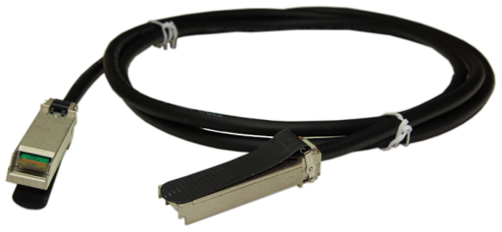
Models and specifications
Table 89 Specifications for Gigabit SFP copper cables
|
Model |
Transmission distance |
Data rate |
Cable type |
|
SFP-STACK-Kit |
1.5 m (4.92 ft) |
1250 Mbps |
UTP/STP |
|
SFP-STACK-Kit-S |
1.5 m (4.92 ft) |
1250 Mbps |
UTP/STP |
Hybrid copper-fiber transceiver modules
The hybrid copper-fiber transceiver module must be used in conjunction with the hybrid copper-fiber pigtail and hybrid copper-fiber cable for data transmission and power supply/reception.
The hybrid copper-fiber cable jumper can connect device over a short distance for data transmission and power supply/reception.
SFP+ hybrid copper-fiber transceiver modules (PELC interface)
Figure 56 SFP+ hybrid copper-fiber transceiver module (PELC interface)
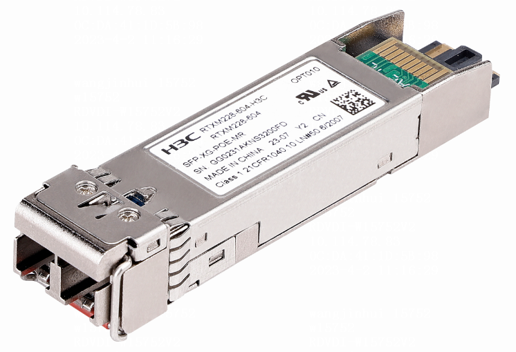
Models and specifications
SFP+ hybrid copper-fiber transceiver modules are multi-rate transceiver modules that use PELC connectors and provide a transmission rate of 10 Gbps, 5 Gbps, 2.5 Gbps, or 1 Gbps.
Table 90 Specifications for SFP+ hybrid copper-fiber transceiver modules (1)
|
Model |
Central wavelength (nm) |
Fiber mode |
Fiber diameter (μm) |
Transmission distance |
|
*SFP-XG-POE-MR |
1310 |
SMF |
9/125 |
1.4 km (0.87 miles) |
Table 91 Specifications for SFP+ hybrid copper-fiber transceiver modules (2)
|
Model |
Optical parameters (dBm) |
|
|
Transmit power |
Receive power |
|
|
*SFP-XG-POE-MR |
–8.2 to +0.5 |
–12.6 to +0.5 |
SFP hybrid copper-fiber transceiver modules (PELC interface)
Figure 57 SFP hybrid copper-fiber transceiver module (PELC interface)

Models and specifications
SFP hybrid copper-fiber transceiver modules provide a transmission rate of 1250 Mbps and use PELC connectors.
Table 92 Specifications for SFP hybrid copper-fiber transceiver modules (1)
|
Model |
Central wavelength (nm) |
Fiber mode |
Fiber diameter (μm) |
Transmission distance |
|
*SFP-GE-POE |
1310 |
SMF |
9/125 |
10 km (6.21 miles) |
Table 93 Specifications for SFP hybrid copper-fiber transceiver modules (2)
|
Model |
Optical parameters (dBm) |
|
|
Transmit power |
Receive power |
|
|
*SFP-GE-POE |
–9 to –1 |
–18.7 to –3 |
Hybrid copper-fiber cable jumpers
Figure 58 Hybrid copper-fiber cable jumpers
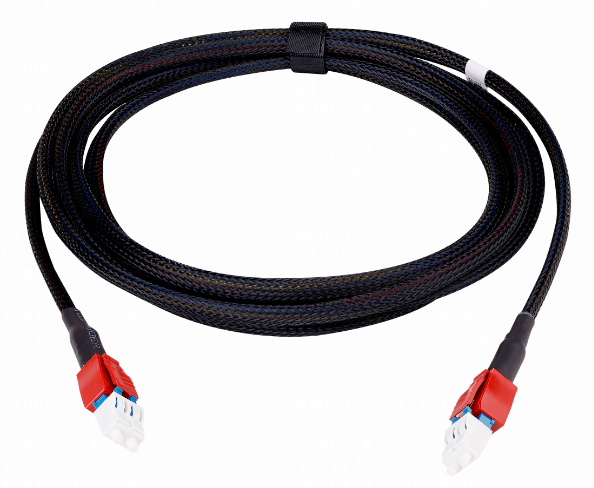
Models and specifications
Table 94 Specifications for hybrid copper-fiber cable jumpers
|
Model |
Length |
|
PoE-PELC-PELC-0.3 |
0.3 m (0.98 ft) |
|
PoE-PELC-PELC-1.5 |
1.5 m (4.92 ft) |
|
PoE-PELC-PELC-3.0 |
3.0 m (9.84 ft) |
Hybrid copper-fiber cable pigtail
Figure 59 Hybrid copper-fiber cable pigtail
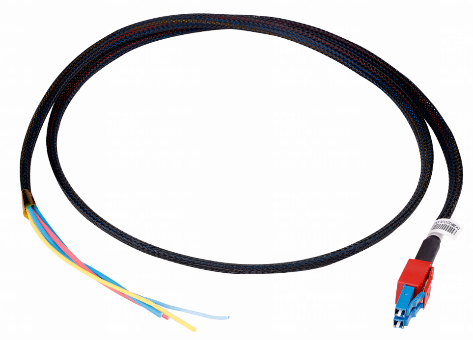
Models and specifications
Table 95 Specifications for the hybrid copper-fiber cable pigtail
|
Model |
Length |
|
PoE-PELC-ODF-0.4m |
0.4 m (1.31 ft) |
|
PoE-PELC-ODF-1.2m |
1.2 m (3.94 ft) |
iOptic 3.0 dedicated transceiver modules
The iOptic 3.0 dedicated transceiver module must be used in conjunction with the combined copper-fiber pigtail and hybrid copper-fiber cable for data transmission and power supply/reception.
SFP28 iOptic 3.0 dedicated transceiver modules (LC interface)
Figure 60 SFP28 iOptic 3.0 dedicated transceiver modules

Models and specifications
SFP28 iOptic 3.0 dedicated transceiver modules use PoDLC connectors and provide a transmission rate of 25 Gbps.
Table 96 Specifications for SFP28 iOptic 3.0 dedicated transceiver modules (1)
|
Model |
Central wavelength (nm) |
Fiber mode |
Fiber diameter (μm) |
Modal bandwidth (MHz*km) |
Transmission distance |
|
SFP-25G-LR-SM1310-F |
1310 |
SMF |
9/125 |
- |
10 km (6.21 miles) |
Table 97 Specifications for SFP28 iOptic 3.0 dedicated transceiver modules (2)
|
Model |
Optical parameters (dBm) |
|
|
Transmit power |
Receive power |
|
|
SFP-25G-LR-SM1310-F |
–7 to +2 |
–13.3 to +2 |
SFP+ iOptic 3.0 dedicated transceiver modules (LC interface)
Figure 61 SFP+ iOptic 3.0 dedicated transceiver module
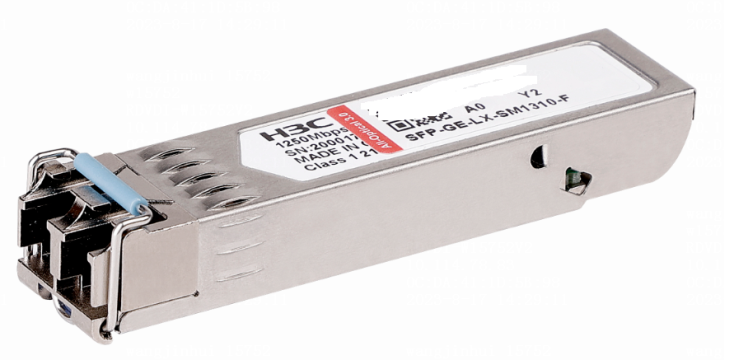
Models and specifications
SFP+ iOptic 3.0 dedicated transceiver modules provide a transmission rate of 10 Gbps and use PoDLC connectors.
Table 98 Specifications for SFP+ iOptic 3.0 dedicated transceiver modules (1)
|
Model |
Central wavelength (nm) |
Fiber mode |
Fiber diameter (μm) |
Modal bandwidth (MHz*km) |
Transmission distance |
|
SFP-XG-LX-SM1310-F |
1310 |
SMF |
9/125 |
- |
10 km (6.21 miles) |
Table 99 Specifications for SFP+ iOptic 3.0 dedicated transceiver modules (2)
|
Model |
Optical parameters (dBm) |
|
|
Transmit power |
Receive power |
|
|
SFP-XG-LX-SM1310-F |
–8.2 to +0.5 |
–14.4 to +0.5 |
2.5G SFP iOptic 3.0 dedicated transceiver modules (LC interface)
Figure 62 2.5G SFP iOptic 3.0 dedicated transceiver module

Models and specifications
The 2.5G SFP iOptic 3.0 dedicated transceiver module is a multi-rate transceiver module, providing transmission rates of 2.5 Gbps and 1 Gbps. These transceiver modules use PoDLC connectors
Table 100 Specifications for 2.5G SFP iOptic 3.0 dedicated transceiver modules (1)
|
Model |
Central wavelength (nm) |
Fiber mode |
Fiber diameter (μm) |
Modal bandwidth (MHz*km) |
Transmission distance |
|
*SFP-2.5G-LX10-SM1310-DR-I-F |
1310 |
SMF |
9/125 |
- |
10 km (6.21 miles) |
Table 101 Specifications for SFP iOptic 3.0 dedicated transceiver modules (2)
|
Model |
Optical parameters (dBm) |
|
|
Transmit power |
Receive power |
|
|
*SFP-2.5G-LX10-SM1310-DR-I-F |
–5 to –0.5 |
–14.4 to +0.5 |
SFP iOptic 3.0 dedicated transceiver modules (LC interface)
Figure 63 SFP iOptic 3.0 dedicated transceiver module

Models and specifications
The SFP iOptic 3.0 dedicated transceiver modules provide a transmission rate of 1250 Mbps and use PoDLC connectors.
Table 102 Specifications for SFP iOptic 3.0 dedicated transceiver modules (1)
|
Model |
Central wavelength (nm) |
Fiber mode |
Fiber diameter (μm) |
Modal bandwidth (MHz*km) |
Transmission distance |
|
SFP-GE-LX-SM1310-F |
1310 |
SMF |
9/125 |
- |
10 km (6.21 miles) |
Table 103 Specifications for SFP iOptic 3.0 dedicated transceiver modules (2)
|
Model |
Optical parameters (dBm) |
|
|
Transmit power |
Receive power |
|
|
SFP-GE-LX-SM1310-F |
–9.5 to –3.0 |
–20 to –3 |
Combined copper-fiber pigtail
Figure 64 Combined copper-fiber pigtail
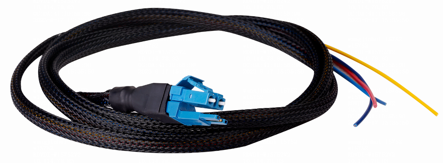
Models and specifications
Table 104 Specifications for the combined copper-fiber pigtail
|
Model |
Cable length |
Transmission rate |
Cable type |
|
PoE-PoDLCA-ODF-1.5m |
1.5 m (4.92 ft) |
- |
Combined copper-fiber pigtail |
