- Table of Contents
- Related Documents
-
| Title | Size | Download |
|---|---|---|
| 01-Hardware Information and Specifications | 1.17 MB |
1 Product models and technical specifications
Product models
The H3C S9825 & S9855 switch series include the following models:
|
Series |
Product model |
Product code |
|
H3C S9825 and S9855 switch series |
S9825-64D |
· LS-9825-64D · LS-9825-64D-H1 |
|
S9855-48CD8D |
LS-9855-48CD8D |
|
|
S9855-24B8D |
LS-9855-24B8D |
The S9825-64D, S9855-48CD8D, and S9855-24B8D switches are high-density converged 400G switch, 100G TOR switch, and 200G TOR switch, respectively, which are developed for high-performance data centers. They can provide powerful hardware forwarding capacity and abundant data center features.
The switch provides the following ports and removable components:
· 400G QSFP-DD ports, 100G DSFP ports, and 200G QSFP56 ports.
· Removable fan trays in redundancy mode.
· Removable power supplies in redundancy mode.
Technical specifications
Table1-1 Technical specifications
|
Item |
S9825-64D |
S9855-48CD8D |
S9855-24B8D |
|
Dimensions (H × W × D) |
175 × 440 × 760 mm (6.89 × 17.32 × 29.92 in) |
44 × 440 × 660 mm (1.73 × 17.32 × 25.98 in) |
44 × 440 × 660 mm (1.73 × 17.32 × 25.98 in) |
|
Weight |
LS-9825-64D: ≤ 37 kg (81.57 lb) LS-9825-64D-H1: ≤ 38.4 kg (84.66 lb) |
≤ 12.2 kg (26.90 lb) |
≤ 12.2 kg (26.90 lb) |
|
Serial console port |
1 |
1 |
1 |
|
Management Ethernet port (RJ-45) |
1 |
1 |
1 |
|
USB 2.0 port |
1 |
1 |
1 |
|
DSFP port |
N/A |
48 |
N/A |
|
QSFP56 port |
N/A |
N/A |
24 |
|
QSFP-DD |
64 |
8 |
8 |
|
Fan tray slot |
LS-9825-64D: 6 LS-9825-64D-H1: 8 |
6 |
6 |
|
Power supply slot |
4 |
2 |
2 |
|
Minimum power consumption |
LS-9825-64D: · Dual AC inputs: 243 W · Four AC inputs: 251 W LS-9825-64D-H1: · Dual AC inputs: 247 W · Four AC inputs: 256 W |
Single AC input: 125 W Dual AC inputs: 140 W |
Single AC input: 133 W Dual AC inputs: 146 W |
|
Typical power consumption |
LS-9825-64D: · Dual AC inputs: 613 W · Four AC inputs: 630 W LS-9825-64D-H1: · Dual AC inputs: 650 W · Four AC inputs: 680 W |
Single AC input: 238 W Dual AC inputs: 250 W |
Single AC input: 251 W Dual AC inputs: 263 W |
|
Maximum power consumption |
LS-9825-64D: · Dual AC inputs: 1852 W · Four AC inputs: 1855 W LS-9825-64D-H1: · Dual AC inputs: 2500 W · Four AC inputs: 2500 W |
Single AC input: 713 W Dual AC inputs: 719 W |
Single AC input: 739 W Dual AC inputs: 748 W |
|
Chassis leakage current compliance |
· UL60950-1 · EN60950-1 · IEC60950-1 · GB4943 |
||
|
Sound pressure level at 27°C (80.6°F) |
LS-9825-64D: 60.9 dB(A) LS-9825-64D-H1: 59.7 dB(A) |
59.5 dB(A) |
59.5 dB(A) |
|
Operating temperature |
0°C to 40°C (32°F to 104°F) |
||
|
Operating humidity |
5% RH to 95% RH, noncondensing |
||
|
Fire resistance compliance |
· UL60950-1 · EN60950-1 · IEC60950-1 · GB4943 |
||
Table1-2 Power consumption data collection standard
|
Item |
Static power consumption |
Typical power consumption |
Maximum power consumption |
|
Configuration |
No transceiver modules/cables installed in ports |
Fully configured with copper cables |
Fully configured with transceiver modules |
|
Load |
N/A |
50% load |
100% load |
2 Chassis views
S9825-64D
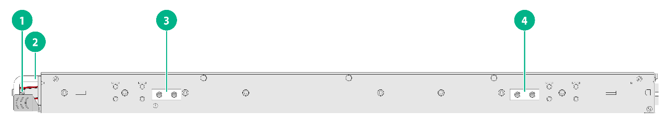
Figure2-1 S9825-64D front panel

|
(1) Management Ethernet port |
(2) Management Ethernet port LED (LINK/ACT) |
|
(3) USB port |
(4) Reset button (RESET) |
|
(5) QSFP-DD port |
(6) QSFP-DD port LED |
|
(7) System status LED (SYS) |
(8) Fan tray status LED (FAN) |
|
(9) Power supply status LED (PSU) |
(10) Console port |
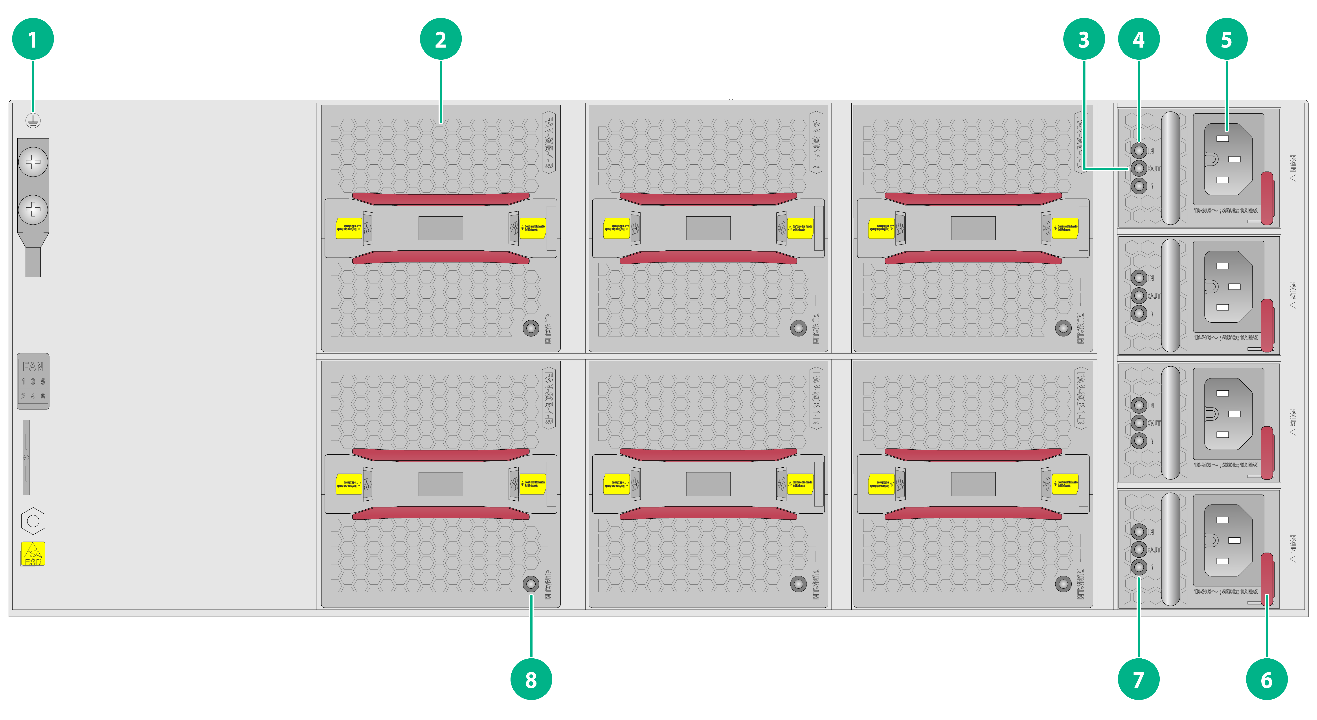
Figure2-2 S9825-64D rear panel (LS-9825-64D)
|
(1) Grounding screw |
(2) Fan tray |
|
(3) Power output status LED (OUT) |
(4) Power input status LED (IN) |
|
(5) Power input receptacle |
(6) Power supply latch |
|
(7) Power supply fault LED (!) |
(8) Fan tray alarm LED (RUN/ALM) |
The S9825-64D switch came with power supply slot PSU1 empty and power supply slots PSU2, PSU3, and PSU4 each installed with a filler panel. You can install two or multiple power supplies for the switch as needed. In Figure2-2, four PSR1600C-12A-B AC power supplies are installed in the power supply slots.
The S9825-64D switch model includes switches with the LS-9825-64D and LS-9825-64D-H1 product codes. The switch with the LS-S9825-64D product code came with the six fan tray slots empty. The switch with the LS-9825-64D-H1 product code came with the eight fan tray slots empty. You must install fan trays of the same model for the switch. In Figure2-2, six FAN-80B-1-B fan trays are installed in the fan tray slots on the switch with the LS-S9825-64D product code.
Figure2-3 S9825-64D left panel
|
(1) Fan tray handle |
(2) Power supply handle |
|
(3) Chassis handle |
|
S9855-48CD8D
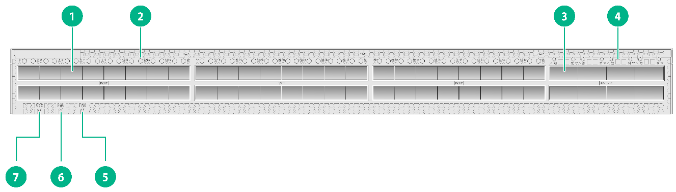
Figure2-4 S9855-48CD8D front panel
|
(1) DSFP port |
(2) DSFP port LED |
|
(3) QSFP-DD port |
(4) QSFP-DD port LED |
|
(5) Fan tray status LED (FAN) |
(6) Power supply status LED (PSU) |
|
(7) System status LED (SYS) |
|
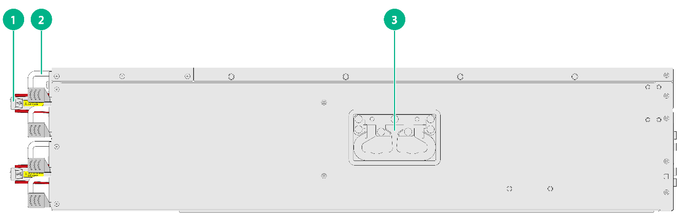
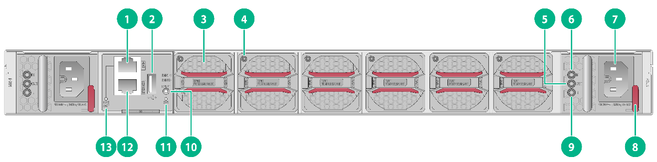
Figure2-5 S9855-48CD8D rear panel

|
(1) Management Ethernet port |
(2) USB port |
|
(3) Fan tray |
(4) Fan tray alarm LED |
|
(5) Power output status LED (OUT) |
(6) Power input status LED (IN) |
|
(7) Power input receptacle |
(8) Power supply latch |
|
(9) Power supply fault LED (!) |
(10) Reset button (RESET) |
|
(11) System status LED (SYS) |
(12) Console port |
|
(13) Management Ethernet port LED (LINK/ACT) |
|
The S9855-48CD8D switch came with power supply slot PSU1 empty and power supply slot PSU2 installed with a filler panel. You can install one or two power supplies for the switch as needed. In Figure2-5, two PSR1600C-12A-B AC power supplies are installed in the power supply slots.
The S9855-48CD8D switch came with the six fan tray slots empty. You must install six fan trays of the same model for the switch. In Figure2-5, six FAN-40B-1-C fan trays are installed in the fan tray slots.
Figure2-6 S9855-48CD8D left panel
|
(1) Fan tray handle |
(2) Power supply handle |
|
(3) Primary grounding point |
(4) Auxiliary grounding point |
S9855-24B8D
Figure2-7 S9855-24B8D front panel
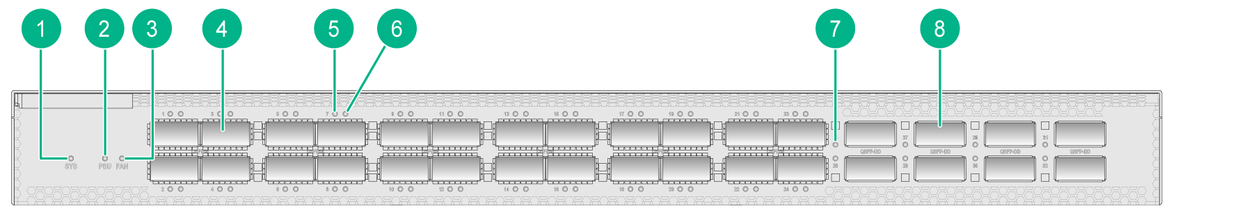
|
(1) System status LED (SYS) |
(2) Power supply status LED (PSU) |
|
(3) Fan tray status LED (FAN) |
(4) QSFP56 port |
|
(5) QSFP56 port LED 1 |
(6) QSFP56 port LED 2 |
|
(7) QSFP-DD port LED |
(8) QSFP-DD port |
Figure2-8 S9855-24B8D rear panel
|
(1) Management Ethernet port |
(2) USB port |
|
(3) Fan tray |
(4) Fan tray alarm LED |
|
(5) Power output status LED (OUT) |
(6) Power input status LED (IN) |
|
(7) Power input receptacle |
(8) Power supply latch |
|
(9) Power supply fault LED (!) |
(10) Reset button (RESET) |
|
(11) System status LED (SYS) |
(12) Console port |
|
(13) Management Ethernet port LED (LINK/ACT) |
|
The S9855-24B8D switch came with power supply slot PSU1 empty and power supply slot PSU2 installed with a filler panel. You can install one or two power supplies for the switch as needed. In Figure2-8, two PSR1600C-12A-B AC power supplies are installed in the power supply slots.
The S9855-24B8D switch came with the six fan tray slots empty. You must install six fan trays of the same model for the switch. In Figure2-8, six FAN-40B-1-C fan trays are installed in the fan tray slots.
Figure2-9 S9855-24B8D left panel

|
(1) Fan tray handle |
(2) Power supply handle |
|
(3) Primary grounding point |
(4) Auxiliary grounding point |
3 Removable components
Removable components available for the switch
The switch uses modular design. Table3-1 describes the removable components available for the switch.
Table3-1 Removable components available for the switch
|
Removable components |
BOM code |
S9825-64D |
S9855-48CD8D |
S9855-24B8D |
|
Power supplies |
||||
|
PSR1600C-12A-B |
0231AFJ7 |
Supported |
Supported |
Supported |
|
Fan trays |
||||
|
FAN-80B-1-B |
0231ABV6 |
Supported |
Not supported |
Not supported |
|
FAN-40B-1-C |
0231AFJ9 |
Not supported |
Supported |
Supported |
|
FAN-40F-1-D |
0231AKLC |
Not supported |
Not supported |
Supported |
The S9855-48CD8D or S9855-24B8D switch can operate correctly with only one power supply. You can install two power supplies for 1+1 redundancy.
The S9825-64D switch can operate correctly with two power supplies. You can install three power supplies for 2+1 redundancy or four power supplies for 2+2 redundancy.
To ensure heat dissipation, make sure all fan tray slots on the S9855-48CD8D and S9855-24B8D switches have fan trays installed and the fan trays are the same model.
The S9825-64D switch with the LS-S9825-64D product code has six fan tray slots. To ensure heat dissipation, make sure all fan tray slots on the switch have fan trays installed and the fan trays are the same model.
The S9825-64D switch with the LS-9825-64D-H1 product code has eight fan tray slots. When you install ZR or ZR+ modules in the two lower rows of ports on the switch, make sure all fan tray slots on the switch have fan trays installed. In other situations, you can install six fan trays in slots FAN3 to FAN8.
Power supplies
|
|
WARNING! When the switch has power supplies in redundancy, you can replace a power supply without powering off the switch. To avoid device damage or bodily injury, make sure the power supply is powered off before you replace it. |
Table3-2 Power supply specifications
|
Power supply model |
Specifications |
Remarks |
|
PSR1600C-12A-B |
· Rated AC input voltage: 100 VAC to 240 VAC @ 50 Hz or 60 Hz · Rated HVDC input voltage: 180 VDC to 320 VDC · Max output power: 1600 W · Melting current of the power supply fuse: 10 A/250 V |
For more information about the power supply, see H3C PSR1600C-12A-B Power Module User Manual. |
Fan trays
Table3-3 Fan tray specifications
|
Fan tray model |
Item |
Specifications |
|
FAN-80B-1-B (from the port side to the power supply side) |
Dimensions (including the handle) |
84 × 81 × 240 mm (3.31 × 3.19 × 9.45 in) |
|
Fan speed |
12800 R.P.M |
|
|
Maximum airflow |
130 CFM (3.68 m3/min) |
|
|
Input voltage |
12 V |
|
|
Maximum power consumption |
102 W |
|
|
Documentation reference |
H3C FAN-80B-1-B Fan tray User Guide |
|
|
FAN-40B-1-C (from the port side to the power supply side) |
Dimensions (including the handle) |
40 × 40 × 136 mm (1.57 × 1.57 × 5.35 in) |
|
Fan speed |
29000 R.P.M |
|
|
Maximum airflow |
38 CFM (1.08 m3/min) |
|
|
Input voltage |
12 V |
|
|
Maximum power consumption |
60 W |
|
|
Documentation reference |
H3C FAN-40B-1-C Fan Tray User Guide |
|
|
FAN-40F-1-D (from the power supply side to the port side) |
Dimensions (including the handle) |
40 × 40 × 136 mm (1.57 × 1.57 × 5.35 in) |
|
Fan speed |
29000 R.P.M |
|
|
Maximum airflow |
38 CFM (1.08 m3/min) |
|
|
Input voltage |
12 V |
|
|
Maximum power consumption |
60 W |
4 Ports and LEDs
As a best practice, use H3C transceiver modules and cables for the switch. H3C transceiver modules and cables are subject to change over time. For the most up-to-date list of H3C transceiver modules and cables, contact H3C Support or marketing staff.
For information about the specifications of H3C transceiver modules and cables, see H3C Transceiver Modules User Guide.
Ports
Console port
The switch has a serial console port.
Table4-1 Console port specifications
|
Item |
Serial console port |
|
Connector type |
RJ-45 |
|
Compliant standard |
EIA/TIA-232 |
|
Transmission baud rate |
9600 bps (default) to 115200 bps |
|
Services |
· Provides connection to an ASCII terminal. · Provides connection to the serial port of a local terminal (a PC for example) running a terminal emulation program. |
Management Ethernet port
The switch has a copper management Ethernet port. You can connect the port to a local PC for software loading and debugging or to a remote management station for remote management.
Table4-2 Management Ethernet port specifications
|
Item |
Specification |
|
Connector type |
RJ-45 |
|
Port quantity |
1 × management 10/100/1000BASE-T port |
|
Port transmission rate, duplex mode, and auto MDI/MDI-X |
· 10/100 Mbps, half/full duplex, auto MDI/MDI-X · 1000 Mbps, full duplex, auto MDI/MDI-X |
|
Transmission medium and max transmission distance |
100 m (328.08 ft) over category 5 UTP cable |
|
Functions and services |
Software upgrade and network management. |
USB port
The switch has one OHCI-compliant USB 2.0 port that can upload and download data at a rate up to 480 Mbps. You can use this USB port to access the file system on the flash of the switch, for example, to upload or download application and configuration files.
The USB port supplies power as per USB 2.0 specifications. Use only USB 2.0-compliant USB devices for the USB port. The port might not identify USB devices that are not compliant with USB 2.0.
|
|
NOTE: USB devices from different vendors vary in compatibilities and drivers. H3C does not guarantee correct operation of USB devices of all vendors on the switch. If a USB device fails to operate on the switch, replace it with one from another vendor. |
DSFP port
The S9855-48CD8D switch provides 48 DSFP ports. Purchase DSFP transceiver modules yourself as needed.
QSFP-DD port
The S9825-64D switch with the LS-9825-64D or LS-9825-64D-H1 product code provides 64 QSFP-DD ports. You can install ZR modules in the upper row of ports on the switch. For the S9825-64D switch with the LS-9825-64D-H1 product code, you can also install ZR or ZR+ modules in the two lower rows of ports. The 48 ports that support ZR modules on the switch are in pink.
The S9855-48CD8D and S9825-24B8D switches each provide eight QSFP-DD ports.
QSFP-DD ports support the following transceiver modules and cables:
· QSFP28 transceiver modules.
· QSFP28 cables.
· QSFP56 transceiver modules.
· QSFP-DD transceiver modules.
· QSFP-DD cables.
The QSFP-DD ports on the S9825-64D switch also support QSFP-DD to 2×200G QSFP56 cables. Such cables are not provided. Purchase them yourself as required.
QSFP56 port
The S9825-24B8D switch provides 24 QSFP56 ports.
QSFP56 ports support the following transceiver modules and cables:
· QSFP28 transceiver modules.
· QSFP28 cables.
· QSFP56 transceiver modules.
· QSFP56 cables and QSFP56 to 2×100G QSFP28 cables. Such cables are not provided. Purchase them yourself as required.
LEDs
Panel LEDs
System status LED
The system status LED shows the operating status of the switch.
Table4-3 System status LED description
|
LED mark |
Status |
Description |
|
SYS |
Steady green |
The switch is operating correctly. |
|
Flashing green |
The switch is performing power-on self-test (POST) or downloading software. |
|
|
Steady red |
The system has failed to pass POST, a fault has occurred, or an overtemperature condition has occurred. |
|
|
Steady yellow |
The number of fan trays or power supplies on the switch is abnormal. |
|
|
Off |
The switch is powered off or has failed to start up. |
DSFP port LED
The switch provides a DSFP port LED for each DSFP port to indicate their operating status.
Table4-4 DSFP port LED description
|
LED status |
Description |
|
Steady green |
A transceiver module or cable has been correctly installed in the port. The port is operating at its maximum speed of 100 Gbps, and a link is present on the port. |
|
Flashing green |
The port is sending or receiving data at its maximum speed of 100 Gbps. |
|
Steady yellow |
A transceiver module or cable has been correctly installed in the port. The port is operating at a speed lower than the maximum speed, and a link is present on the port. |
|
Flashing yellow |
The port is sending or receiving data at a speed lower than the maximum speed. |
|
Off |
No transceiver module or cable has been installed in the port, or no link is present on the port. |
QSFP56 port LED
Each QSFP56 port has two status LEDs to indicate port operating status and activities. Table4-5 provides the LED description for a QSFP56 port that is not split. Table4-6 provides the LED description for a QSFP56 port split into two breakout interfaces.
Table4-5 LED description for a QSFP56 port that is not split
|
LED status |
Description |
|
Steady green |
A transceiver module or cable has been correctly installed in the port. The port is operating at its maximum speed of 200 Gbps, and a link is present on the port. |
|
Flashing green |
The port is sending or receiving data at its maximum speed of 200 Gbps. |
|
Steady yellow |
A transceiver module or cable has been correctly installed in the port. The port is operating at a speed lower than the maximum speed, and a link is present on the port. |
|
Flashing yellow |
The port is sending or receiving data at a speed lower than the maximum speed. |
|
Off |
No transceiver module or cable has been installed in the port, or no link is present on the port. |
Table4-6 LED description for a QSFP56 port split into two breakout interfaces
|
LED status |
Description |
|
Steady green |
A transceiver module or cable has been correctly installed in the port. The port is operating at its maximum speed of 100 Gbps, and a link is present on the port. |
|
Flashing green |
The port is sending or receiving data at its maximum speed of 100 Gbps. |
|
Off |
No transceiver module or cable has been installed in the port, or no link is present on the port. |
|
|
NOTE: When the port is split into two breakout interfaces, QSFP56 port LED 1 indicates the operating status of the first breakout interface and QSFP56 port LED 2 indicates the operating status of the second breakout interface. For the LED description, see Table4-6. |
QSFP-DD port LED
The switch provides a QSFP-DD port LED for each QSFP-DD port to indicate their operating status.
Table4-7 QSFP-DD port LED description
|
LED status |
Description |
|
Steady green |
A transceiver module is installed in the port. The port is operating at its maximum speed of 400 Gbps, and a link is present on the port. |
|
Flashing green |
The port is sending or receiving data at its maximum speed of 400 Gbps. |
|
Steady yellow |
A transceiver module is installed in the port. The port is operating at a speed lower than the maximum speed, and a link is present on the port. |
|
Flashing yellow |
The port is sending or receiving data at a speed lower than the maximum speed. |
|
Off |
No transceiver module is installed in the port, or no link is present on the port. |
Management Ethernet port LED
The switch provides a LINK/ACT LED for the copper management Ethernet port to indicate its operating status.
Table4-8 Management Ethernet port LED description
|
LED mark |
Status |
Description |
|
LINK/ACT |
Off |
No link is present on the port. |
|
Steady green |
The port is operating at 1000 Mbps. |
|
|
Flashing green |
The port is receiving or sending data at 1000 Mbps. |
|
|
Steady yellow |
The port is operating at 10/100 Mbps. |
|
|
Flashing yellow |
The port is receiving or sending data at 10/100 Mbps. |
Fan tray status LED
The switch provides a fan tray status LED for the fan trays to indicate their operating status.
Table4-9 Fan tray status LED description
|
LED mark |
Status |
Description |
|
FAN |
Steady green |
All fan trays are operating correctly. |
|
Steady yellow |
A fan tray is faulty or not in position. |
|
|
Steady red |
More than one fan tray is faulty or not in position. |
Power supply status LED
The switch provides a power supply status LED for the power supplies to indicate their operating status.
Table4-10 Power supply status LED description
|
LED mark |
Status |
Description |
|
PSU |
Steady green |
All power supplies are operating correctly. |
|
Steady yellow |
A power supply is faulty or not in position. |
|
|
Steady red |
More than one power supply is faulty or not in position. |
Fan tray alarm LED
The switch supports FAN-80B-1-B and FAN-40B-1-C fan trays. A FAN-80B-1-B or FAN-40B-1-C fan tray provides an alarm LED to indicate its operating status.
Table4-11 Description for the alarm LED on a FAN-80B-1-B or FAN-40B-1-C fan tray
|
Status |
Description |
|
Steady green |
The fan tray is operating correctly. |
|
Steady red |
The fan tray is faulty. |
|
Off |
The fan tray is not securely installed or no power is present. |
Power supply LEDs
The switch supports the PSR1600C-12A-B power supply. A PSR1600C-12A-B power supply provides three status LEDs to indicate its operating status.
Table4-12 Description for the alarm LED on a PSR1600C-12A-B power supply
|
LED |
LED mark |
Status |
Description |
|
Power input status LED |
IN |
Steady green |
The power is being input correctly. |
|
Off |
No power is being input or the rated input voltage range has been exceeded. |
||
|
Power output status LED |
OUT |
Steady green |
The power is being output correctly. |
|
Off |
No power is being output. |
||
|
Power supply fault LED |
! |
Flashing yellow |
The power supply is faulty. |
|
Off |
The power supply is operating correctly. |
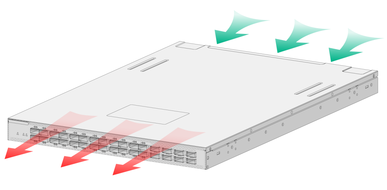
5 Cooling system
|
|
CAUTION: The chassis and power supplies use separate air aisles. Make sure the two aisles are not blocked when the switch is operating. |
The switch uses a highly efficient front-rear air aisle cooling system to ensure adequate heat dissipation and improve system reliability. Consider the ventilation design at the installation site when you plan the installation location for the switch.
Table5-1 Fan tray options for the switch
|
Switch model |
Available fan tray |
Airflow direction of the chassis |
|
S9825-64D |
FAN-80B-1-B |
From the port side to the power supply side |
|
S9855-48CD8D |
FAN-40B-1-C |
From the port side to the power supply side |
|
S9855-24B8D |
FAN-40B-1-C |
From the port side to the power supply side |
|
S9855-24B8D |
FAN-40F-1-D |
From the power supply side to the port side |
Figure5-1 Airflow from the port side to the power supply side through the S9825-64D chassis
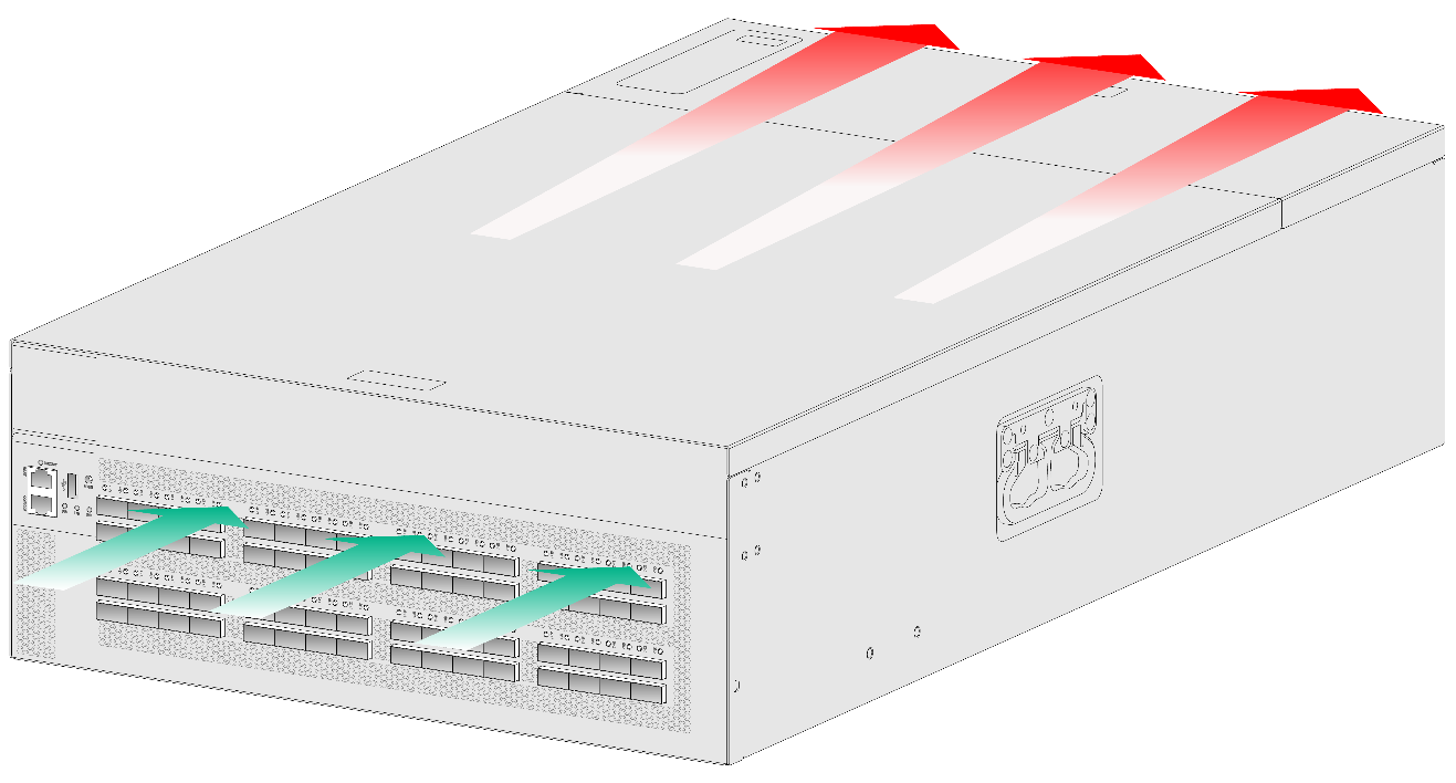
Figure5-2 Airflow from the port side to the power supply side through the S9855-48CD8D chassis
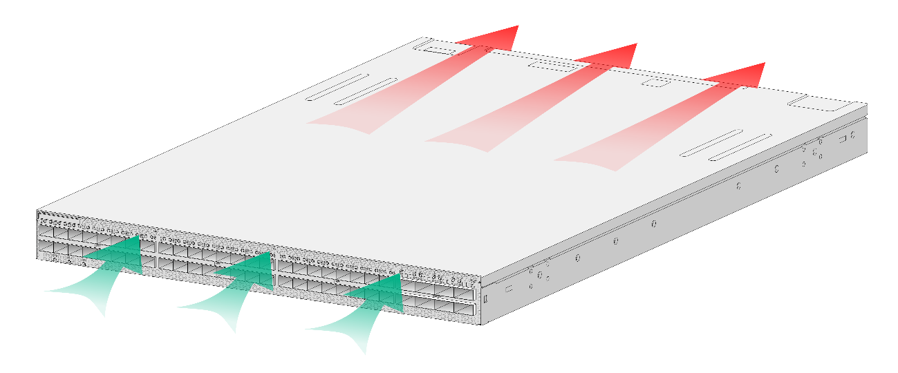
Figure5-3 Airflow from the port side to the power supply side through the S9855-24B8D chassis
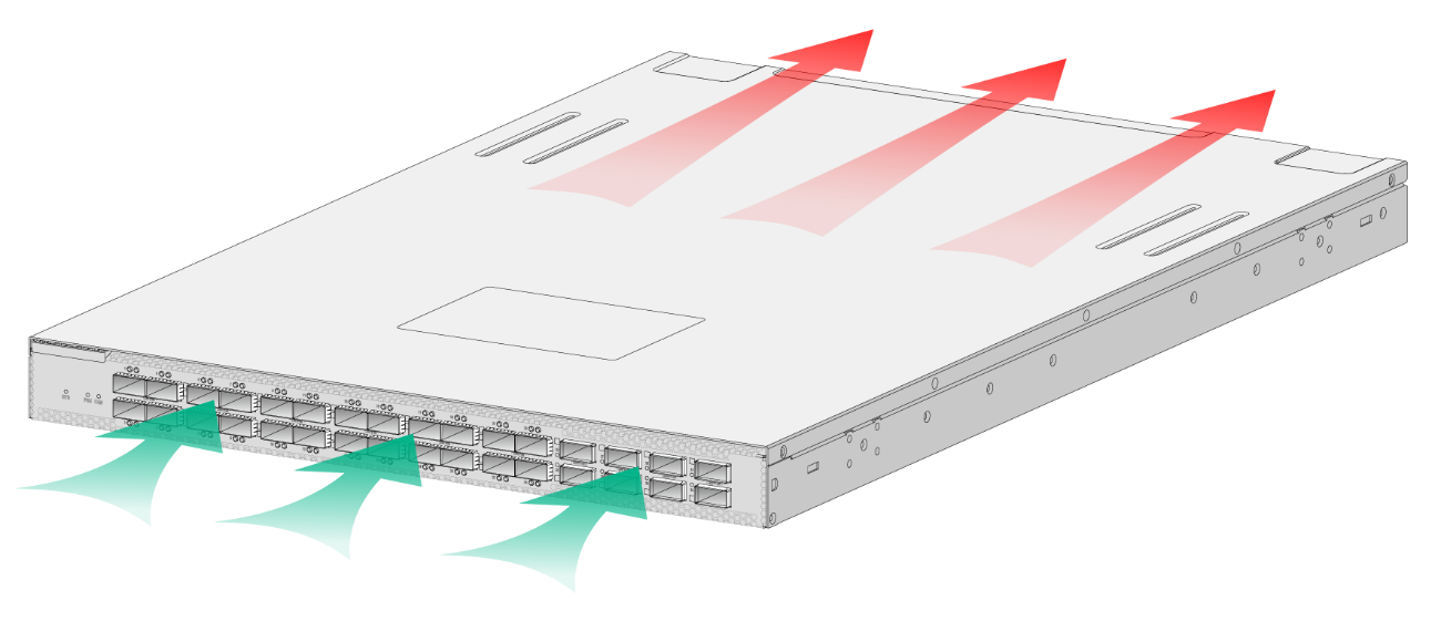
Figure5-4 Airflow from the power supply side to the port side through the S9855-24B8D chassis