- Table of Contents
- Related Documents
-
| Title | Size | Download |
|---|---|---|
| 01-Installation Guide | 2.59 MB |
Examining the installation site
Installing the switch in a 19-inch rack
Rack-mounting procedure at a glance
Mounting brackets, chassis rails, and grounding cable installation positions
Attaching mounting brackets and chassis rails to the switch
Connecting the grounding cable to the switch
Installing and removing power supplies
3 Accessing the switch for the first time
Connecting the switch to a configuration terminal
Connecting the serial console cable
4 Maintenance and troubleshooting
Configuration terminal display issues
1 Preparing for installation
The H3C S9825 & S9855 switch series include the following models:
|
Series |
Product model |
Product code |
|
H3C S9825 and S9855 switch series |
S9825-64D |
· LS-9825-64D · LS-9825-64D-H1 |
|
S9855-48CD8D |
LS-9855-48CD8D |
|
|
S9855-24B8D |
LS-9855-24B8D |
The S9825-64D is a 400G high-density aggregation switch. The S9855-48CD8D is a 100G high-density ToR switch. The S9855-24B8D is a 200G high-density ToR switch. These switches are designed for high-performance data centers and provide powerful hardware forwarding capacity and abundant data center features.
The switch series provides the following ports and removable components:
· 400G QSFP-DD ports, 100G DSFP ports, and 200G QSFP56 ports.
· Removable fan trays that can be configured in redundancy mode.
· Removable power supplies that can be configured in redundancy mode.
Safety recommendations
To avoid any equipment damage or bodily injury caused by incorrect use, read the following safety recommendations before installation. Note that the recommendations do not cover every possible hazardous condition.
· Before cleaning the switch, remove all power cords from the switch. Do not clean the switch with wet cloth or liquid.
· Do not place the switch near water or in a damp environment. Prevent water or moisture from entering the switch chassis.
· Do not place the switch on an unstable case or desk. The switch might be severely damaged in case of a fall.
· Ensure good ventilation in the equipment room and keep the air inlet and outlet vents of the switch free of obstruction.
· Make sure the operating voltage is in the required range.
· To avoid electrical shocks, do not open the chassis while the switch is operating. As a best practice, do not open the chassis even if the switch is powered off.
· To avoid ESD damage, always wear an ESD wrist strap when replacing a removable component such as a power supply or fan tray.
Examining the installation site
The switch must be used indoors. Make sure the installation site meets the following requirements:
· Adequate clearance is reserved at the air inlet and outlet vents for ventilation.
· The rack has a good ventilation system.
· Identify the hot aisle and cold aisle layout at the installation site, and make sure ambient air flows into the switch from the cold aisle and exhausts to the hot aisle.
· Identify the airflow designs of neighboring devices, and prevent hot air flowing out of the neighboring devices from entering the top device.
· The rack is sturdy enough to support the switch and its accessories.
· The rack is reliably grounded.
To ensure correct operation and long service life of your switch, install it in an environment that meets the requirements described in the following subsections.
Temperature/humidity
Maintain the temperature and humidity in the equipment room in the acceptable ranges.
· Lasting high relative humidity can cause poor insulation, electricity leakage, mechanical property change of materials, and metal corrosion.
· Lasting low relative humidity can cause washer contraction and ESD and cause problems including loose mounting screws and circuit failure.
· High temperature can accelerate the aging of insulation materials and significantly lower the reliability and lifespan of the switch.
For information about the temperature and humidity requirements, see H3C S9825 & S9855 Switch Series Hardware Information and Specifications.
Cleanliness
Dust buildup on the chassis might cause electrostatic adsorption and dust corrosion, resulting in poor contact of metal connectors and contact points. This might shorten the device's lifetime and even cause device failure in the worst case. Table1-1 describes the switch requirement for cleanliness.
Table1-1 Switch requirement for cleanliness
|
Substance |
Particle diameter |
Concentration limit |
|
Dust particles |
≥ 0.5 µm |
≤ 1.8 × 10⁷ particles/m3 |
Corrosive gas limit
Corrosive gases can accelerate corrosion and aging of metal components. Make sure the corrosive gases do not exceed the concentration limits as shown in Table1-2.
Table1-2 Corrosive gas concentration limits
|
Gas |
Average concentration (mg/m3) |
Maximum concentration (mg/m3) |
|
SO2 |
0.3 |
1.0 |
|
H2S |
0.1 |
0.5 |
|
Cl2 |
0.1 |
0.3 |
|
HCI |
0.1 |
0.5 |
|
HF |
0.01 |
0.03 |
|
NH3 |
1.0 |
3.0 |
|
O3 |
0.05 |
0.1 |
|
NOX |
0.5 |
1.0 |
EMI
All electromagnetic interference (EMI) sources, from outside or inside of the switch and application system, adversely affect the switch in the following ways:
· A conduction pattern of capacitance coupling.
· Inductance coupling.
· Electromagnetic wave radiation.
· Common impedance (including the grounding system) coupling.
To prevent EMI, use the following guidelines:
· If AC power is used, use a single-phase three-wire power receptacle with protection earth (PE) to filter interference from the power grid.
· Keep the switch far away from radio transmitting stations, radar stations, and high-frequency devices.
· Use electromagnetic shielding, for example, shielded interface cables, when necessary.
· To prevent signal ports from getting damaged by overvoltage or overcurrent caused by lightning strikes, route interface cables only indoors.
Laser safety
|
|
WARNING! Disconnected optical fibers or transceiver modules might emit invisible laser light. Do not stare into beams or view directly with optical instruments when the switch is operating. |
The switch is a Class 1M laser device.
Installation tools
No installation tools are provided with the switch. Prepare the following tools yourself:
· Phillips screwdriver.
· ESD wrist strap.
· Marker.
Installation accessories
Before installation, make sure you have all the required installation accessories. If an accessory is damaged or lost, use its part No. to purchase a new one. You can find the part No. for the accessories in Table1-3.
Table1-3 Installation accessories
|
Part No. |
Description |
Quantity |
Applicable switch models |
|
2150A0H4 |
Mounting brackets
|
1 kit, provided |
S9825-64D |
|
2150A0AN |
Mounting brackets
|
1 kit, provided |
· S9855-48CD8D · S9855-24B8D |
|
2150A05D |
1U rack-mount rail kit (short slide rails)
|
Provided |
· S9855-48CD8D · S9855-24B8D |
|
N/A |
LSVM1BSR10 bottom support rails
|
Optional |
S9825-64D |
|
N/A |
M6 screw and cage nut
|
User supplied |
· S9855-48CD8D · S9825-64D · S9855-24B8D |
|
0404A0KM |
Grounding cable
|
1, provided |
· S9855-48CD8D · S9825-64D · S9855-24B8D |
|
26010553 |
Grounding screw
|
2, provided |
· S9855-48CD8D · S9825-64D · S9855-24B8D |
|
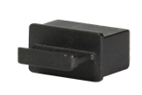
2114A0EE |
Power supply filler panel
|
1, provided |
· S9855-48CD8D · S9855-24B8D |
|
2, provided |
S9825-64D |
||
|
N/A |
Releasable cable tie
|
User supplied |
· S9855-48CD8D · S9825-64D · S9855-24B8D |
|
04042967 |
Console cable
|
User supplied |
· S9855-48CD8D · S9825-64D · S9855-24B8D |
|
14990101 |
SFP port dust plug
|
Same number as the DSFP ports |
S9855-48CD8D |
|
1499A01G |
QSFP port dust plug
|
Same number as the QSFP-DD ports |
· S9855-48CD8D · S9825-64D · S9855-24B8D |


2 Installing the switch
|
|
CAUTION: Keep the tamper-proof seal on a mounting screw on the chassis cover intact, and if you want to open the chassis, contact H3C for permission. Otherwise, H3C shall not be liable for any consequence caused thereby. |

Installing the switch in a 19-inch rack
Rack-mounting procedure at a glance
Figure2-2 Rack-mounting procedure

|
|
NOTE: If a rack shelf is available, you can put the switch on the rack shelf and slide the switch to a position so that the mounting brackets are flush against the front rack posts. Then use screws to secure the mounting brackets to the rack. |
Chassis dimensions
S9825-64D switches with the LS-9825-64D and LS-9825-64D-H1 product codes have the same chassis dimensions. Figure2-3 shows the dimensions of an S9825-64D switch with the LS-9825-64D product code that has mounting brackets installed.
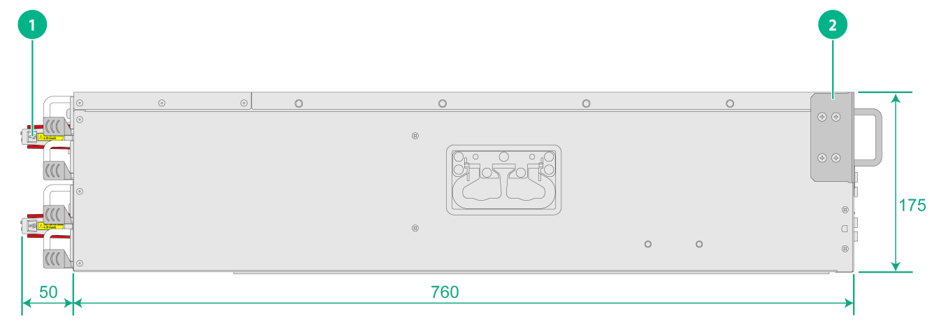
|
(1) Fan tray handle |
(2) Mounting bracket |
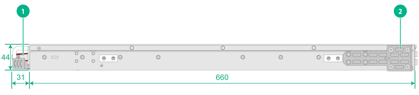
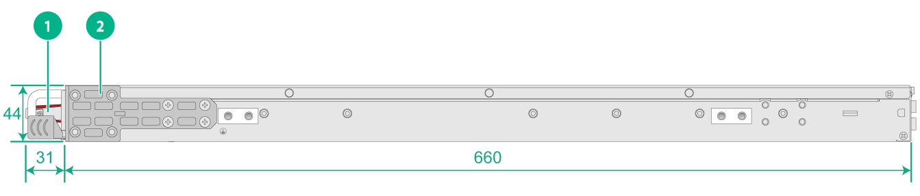
Figure2-4 and Figure2-5 shows the dimensions of the S9855-48CD8D/S9855-24B8D switch.
Figure2-4 S9855-48CD8D/S9855-24B8D switch dimensions with mounting brackets installed at the port side
|
(1) Fan tray handle |
(2) Mounting bracket |
|
(1) Fan tray handle |
(2) Mounting bracket |
Rack requirements
To mount the switch in a 19-inch rack, make sure the rack meets the requirements in Table2-1.
|
Switch model |
Installation method |
Chassis dimensions |
Requirements for the distance between the front and rear rack posts |
Rack depth requirements |
|
S9825-64D |
Bottom support rails (optional) |
· Height—175 mm (6.89 in)/4 RU · Width—440 mm (17.32 in) · Depth—810 mm (31.89 in) ¡ 760 mm (29.92 in) for the chassis ¡ 50 mm (1.97 in) for the fan tray handles |
630 to 900 mm (24.80 to 35.43 in) |
· A minimum of 1000 mm (39.37 in) in depth (recommended) · A minimum of 130 mm (5.12 in) between the front rack post and the front door. · A minimum of 850 mm (33.46 in) between the front rack post and the rear door. |
|
· S9855-48CD8D · S9855-24B8D |
Mounting brackets and short slide rails (provided) |
· Height—44 mm (1.73 in)/4 RU · Width—440 mm (17.32 in) · Depth—691 mm (27.20 in) ¡ 660 mm (25.98 in) for the chassis ¡ 31 mm (1.22 in) for the fan tray handles |
472 to 828 mm (18.58 to 32.60 in) |
· A minimum of 1000 mm (39.37 in) in depth (recommended) · A minimum of 130 mm (5.12 in) between the front rack post and the front door. · A minimum of 750 mm (29.53 in) between the front rack post and the rear door. |
|
|
IMPORTANT: To reserve enough cabling space and close the rack door easily, make sure the rack meets the depth requirements. |
Installation accessories
Table2-3 Installation accessories for rack-mounting the switch
|
Switch model |
Mounting brackets (provided) |
Rack mounting rail kit |
Rack mounting rail kit part No. |
|
S9855-48CD8D S9855-24B8D |
1U high, one pair. See Figure2-6. |
1U high, including one pair of short slide rails and one pair of chassis rails (provided). See Figure2-8 |
2150A05D |
|
S9825-64D |
2U high, one pair. See Figure2-7. |
2U high, including one pair of bottom support rails (optional). See Figure2-9. |
N/A |
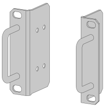
Figure2-6 Mounting brackets provided with the S9855-48CD8D and S9855-24B8D switches
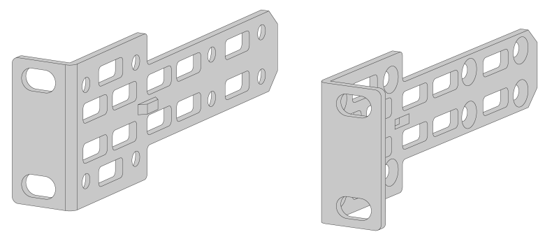
Figure2-7 Mounting brackets provided with the S9825-64D switch
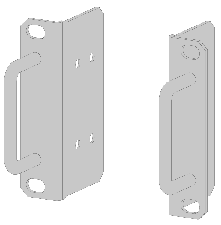
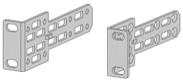
Figure2-8 1U short slide rails and chassis rails
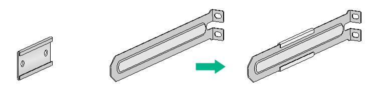
Figure2-9 2U bottom support rails
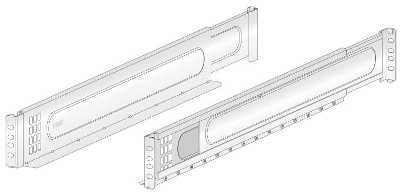
|
(1) Front end mark (FRONT) |
(2) Guide rail |
(3) Installation hole |
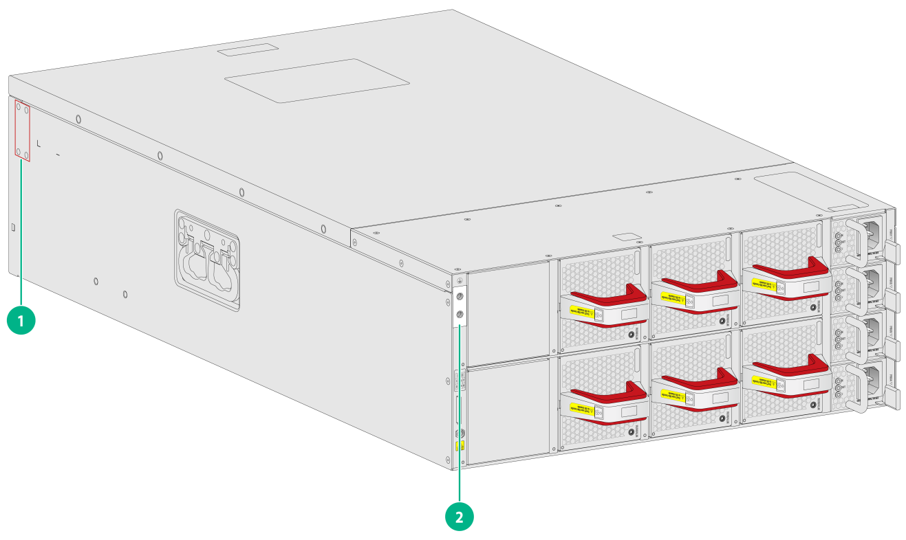
Mounting brackets, chassis rails, and grounding cable installation positions
S9825-64D switches with the LS-9825-64D and LS-9825-64D-H1 product codes have the same mounting bracket and grounding cable installation positions. The S9825-64D switch with the LS-9825-64D product code has one grounding point as shown in Figure2-10.
The S9855-48CD8D and S9855-24B8D switches each provides two grounding points: primary grounding point (with a grounding sign) and auxiliary grounding point, as shown in Figure2-11.
Select installation positions for the mounting brackets, chassis rails, and grounding cable as required.
Figure2-10 Mounting brackets and grounding cable installation positions on the S9825-64D switch
|
(1) Mounting bracket installation position |
(2) Grounding point |
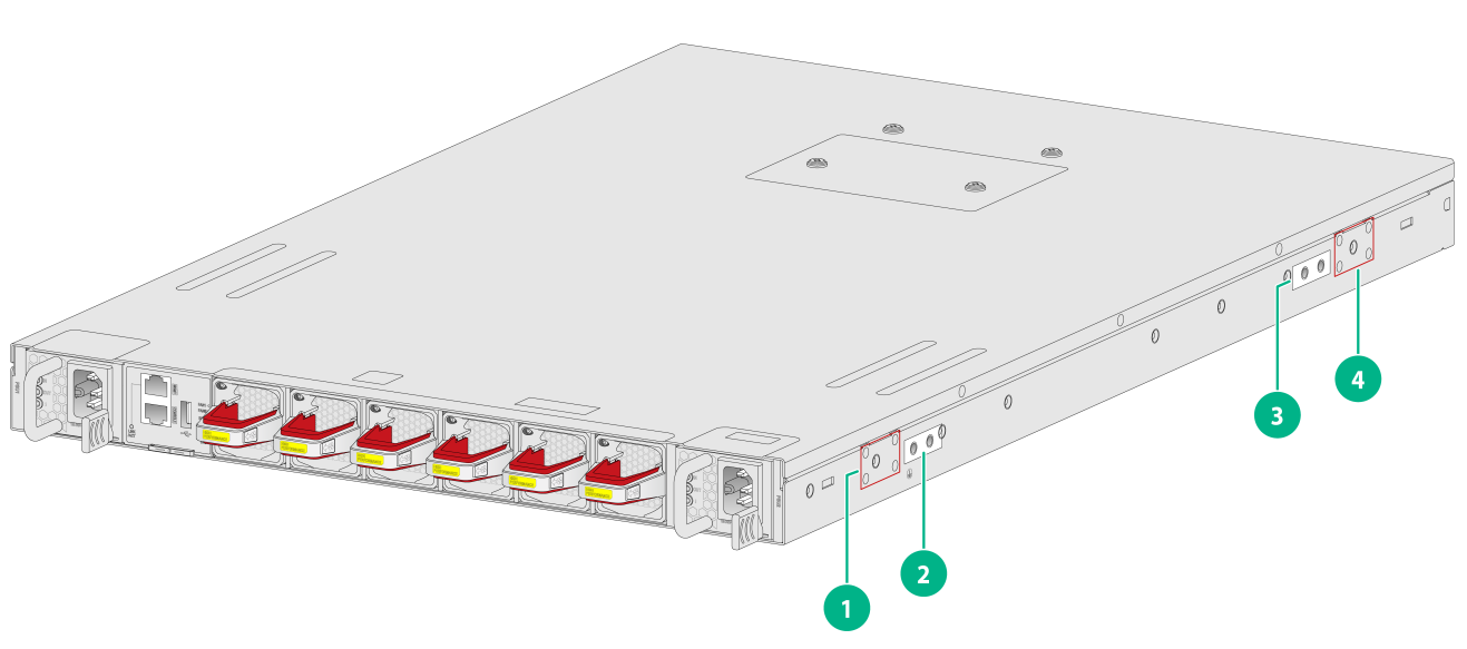
|
(1) Power supply-side installation position for the mounting bracket |
|
|
(2) Primary grounding point |
(3) Auxiliary grounding point |
|
(4) Port-side installation position for the mounting bracket |
|
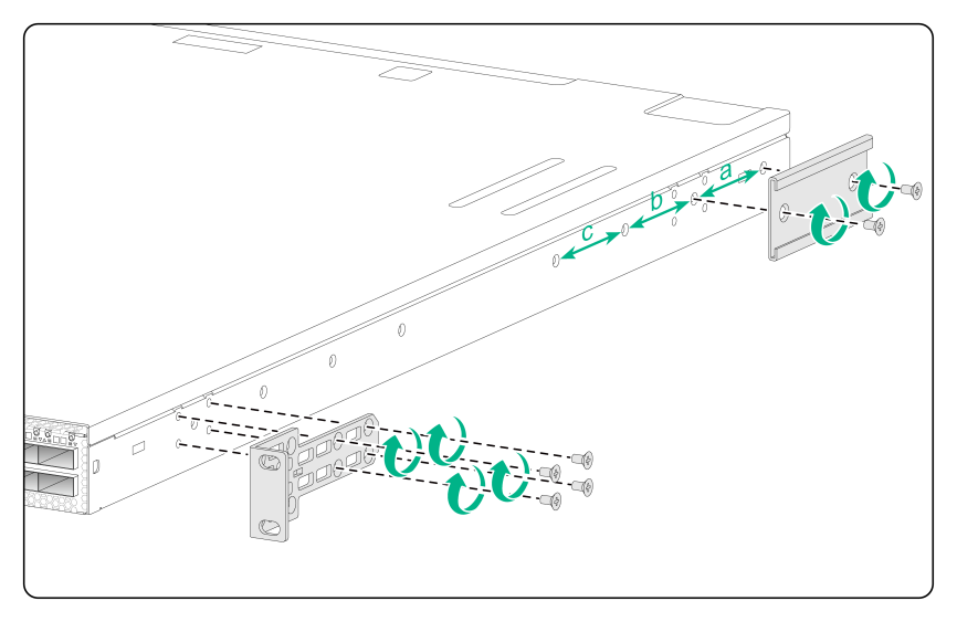
Attaching mounting brackets and chassis rails to the switch
|
|
IMPORTANT: · The S9855-64D switch uses 2U bottom support rails for rack mounting. You are not required to attach chassis rails to it. · M4 screws are used to attach mounting brackets and chassis rails to the switch. As a best practice, use a torque of 12 kgf-cm (1.18 Nm) to fasten M4 screws. |
To attach the mounting brackets and chassis rails to the chassis:
1. Place the wide flange of the mounting bracket against the chassis side panel. Align the mounting bracket installation holes with the screw holes in the side panel. Then use the provided M4 screws to attach the mounting bracket to the chassis.
¡ To install the mounting brackets at the port-side mounting position, see Figure2-12 and Figure2-13.
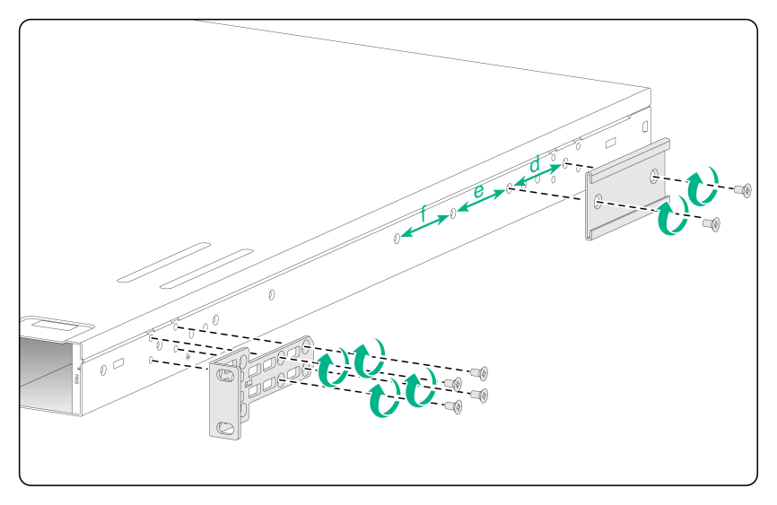
¡ To install the mounting brackets at the power supply-side mounting position, see Figure2-14.
For the S9855-48CD8D and S9855-24B8D switches, use the four installation holes at the narrow side of the mounting brackets for installation.
2. Determine the installation position of the chassis rails based on the position of mounting brackets and the distance between the front and rear rack posts.
Table2-4 Chassis rail installation position
|
Switch model |
Mounting bracket position |
Distance between the front and rear rack posts |
Chassis rail installation position |
|
S9825-64D (2U bottom support rails) |
See Figure2-12. |
630 to 900 mm (24.80 to 35.43 in) |
N/A |
|
S9855-48CD8D S9855-24B8D (short slide rails) |
Port-side installation position for mounting brackets, as shown in Figure2-13. |
650 × 828 mm (25.59 × 32.60 in) |
Position a |
|
585 × 763 mm (23.03 × 30.04 in) |
Position b |
||
|
520 × 698 mm (20.47 × 27.48 in) |
Position c |
||
|
Power supply-side installation position for mounting brackets, as shown in Figure2-14. |
580 × 758 mm (22.83 × 29.84 in) |
Position d |
|
|
515 × 693 mm (20.28 × 27.28 in) |
Position e |
||
|
472 × 628 mm (18.58 × 24.72 in) |
Position f |
3. Place the chassis rail against the chassis side panel. Align the chassis rail installation holes with the screw holes. Use the provided M4 screws to attach the chassis rail to the chassis. See Figure2-13 to Figure2-14.
Figure2-12 Attaching the mounting brackets to the S9825-64D switch
|
|
NOTE: The mounting bracket and chassis rail installation procedures are the same for the left and right chassis side panels. |
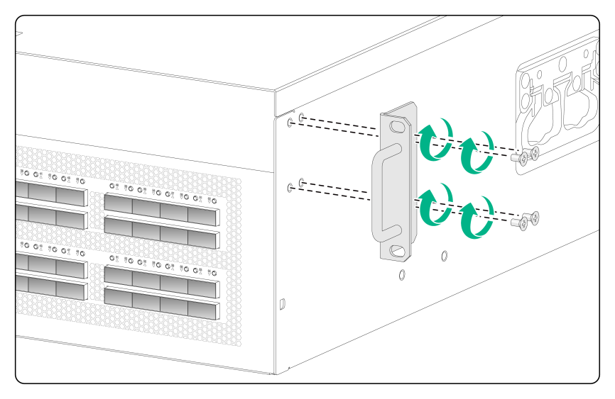
Connecting the grounding cable to the switch
|
|
IMPORTANT: As a best practice, use a torque of 20 kgf-cm (1.96 Nm) to fasten the grounding screws. |
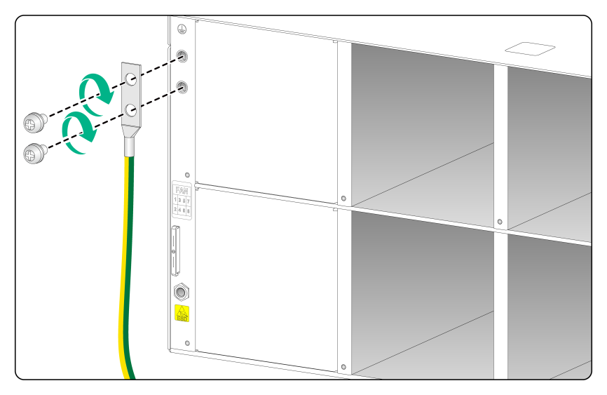
Connecting the grounding cable for the S9825-64D switch
The S9825-64D switch has one grounding point on the rear panel. S9825-64D switches with the LS-9825-64D and LS-9825-64D-H1 product codes have the same grounding cable connection method. The following uses an S9825-64D switch with the LS-9825-64D product code as an example.
To connect the grounding cable to the S9825-64D switch:
1. Unpack the grounding cable and grounding screws.
2. Use the grounding screws to attach the two-hole grounding lug of the grounding cable to the grounding holes at the grounding point. Then use a screwdriver to fasten the screws. See Figure2-15.
Figure2-15 Connecting the grounding cable to an S9825-64D switch
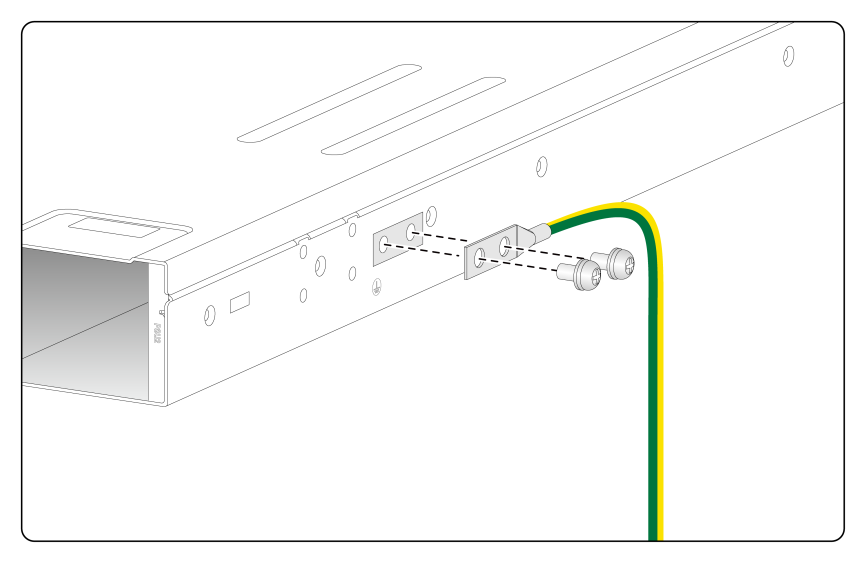
Connecting the grounding cable for the S9855-48CD8D/S9855-24B8D switch
|
|
IMPORTANT: After the switch is mounted in the rack, the grounding points on the side panel will not be reachable. Connect the grounding cable to a grounding point before installing the switch in the rack. |
The S9855-48CD8D and S9855-24B8D switches each provide two grounding points: primary grounding point (with a grounding sign) and auxiliary grounding point on the left side panel.
Select the grounding point based on the mounting bracket installation positions.
· If you install the mounting brackets at the port side, connect the grounding cable to the grounding point (auxiliary) at the port side.
· If you install the mounting brackets at the power supply side, connect the grounding cable to the grounding point (primary) at the power supply side.
The grounding cable connection procedure is similar for using the primary or auxiliary grounding point. The primary grounding point is used as an example in the following figure:
1. Unpack the grounding cable and grounding screws.
2. Use the grounding screws to attach the two-hole grounding lug of the grounding cable to the grounding holes at the grounding point. Then use a screwdriver to fasten the screws. See Figure2-16.
Figure2-16 Connecting the grounding cable to an S9855-48CD8D/S9855-24B8D switch
Rack-mounting the switch
Attaching slide rails or bottom support rails to the rack
|
|
IMPORTANT: M6 screws and cage nuts are used to attach slide rails or bottom support rails to the rack. Prepare M6 screws and cage nuts yourself. As a best practice, use a torque of 30 kgf-cm (2.94 Nm) to fasten the M6 screws. |
Before mounting the switch in the rack, you must attach slide rails or bottom support rails to the rack.
To attach slide rails or bottom support rails to the rack:
1. Identify the installation position of the slide rails and bottom support rails on the rack based on the switch installation position.
2. Attach cage nuts (user-supplied) to the mounting holes in the rack posts.
3. (Applicable to the 1U slide rails.) Align the screw holes in one slide rail with the cage nuts in a rear rack post, and then use M6 screws (user-supplied) to attach the slide rail to the rack, as shown in Figure2-17.
4. (Applicable to the bottom support rails.) Align the screw holes in the two ends of a bottom support rail with the cage nuts in the front and rear rack posts, and then use M6 screws (user-supplied) to attach the slide rail to the rack, as shown in Figure2-18.
5. Attach the other slide rail or bottom support rail to the other rear rack post.
Make sure the two slide rails or bottom support rails are at the same height.
Figure2-17 Installing the 1U slide rails
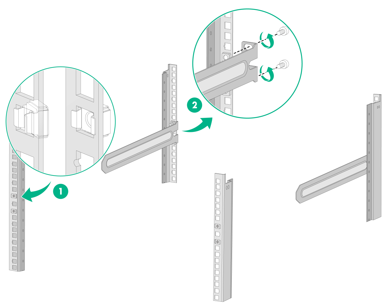
Figure2-18 Installing the bottom support rails
Mounting the switch in the rack
1. Wear an ESD wrist strap and make sure it makes good skin contact and is reliably grounded.
2. Verify that the mounting brackets and chassis rails have been securely attached to the switch chassis.
3. Verify that the slide rails or bottom support rails have been correctly attached to the rear rack posts.
4. Attach cage nuts (user-supplied) to the front rack posts and make sure they are at the same level as the slide rails or bottom support rails.
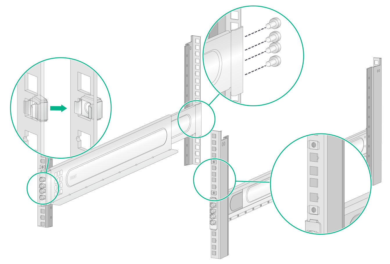
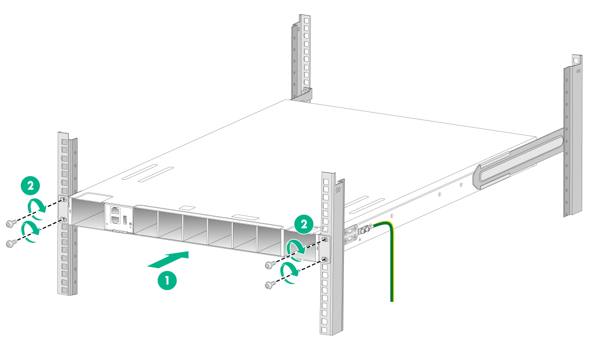
5. (Applicable to the S9855-48CD8D and S9855-24B8D switches) One person performs the following operations:
a. Supporting the bottom of the switch, aligns the chassis rails with the slide rails on the rack posts.
b. Pushes the switch slowly for the slide rails to smoothly slide into the chassis rails until the mounting brackets are flush against the front rack posts. To ensure installation security, make sure the slide rails slide out of the chassis rails a minimum of 20 mm (0.79 in).
6. (Applicable to the S9825-64D switch) One person places the switch on the bottom support rails attached to the rack. Then push the switch slowly into the rack until the mounting brackets are flush against the front rack posts.
7. The other person uses M6 screws (user-supplied, rust-proofed) to attach the mounting brackets to the rack. Make sure the switch is installed level and secure.
As a best practice, use a torque of 30 kgf-cm (2.94 Nm) to fasten the M6 screws.
Figure2-19 Mounting an S9825-64D switch in the rack
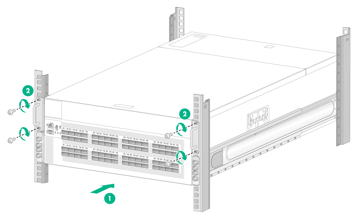
Figure2-20 Mounting an S9855-48CD8D switch in the rack (mounting brackets installed at the port side)
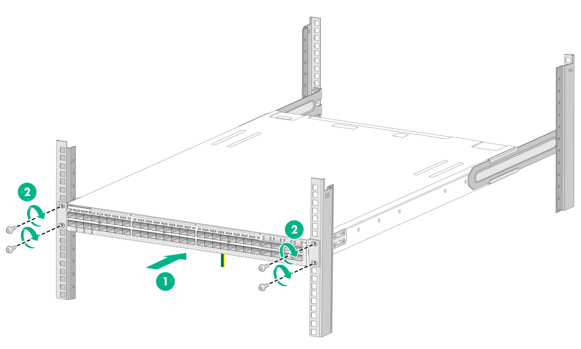
Figure2-21 Mounting an S9855-24B8D switch in the rack (mounting brackets installed at the port side)
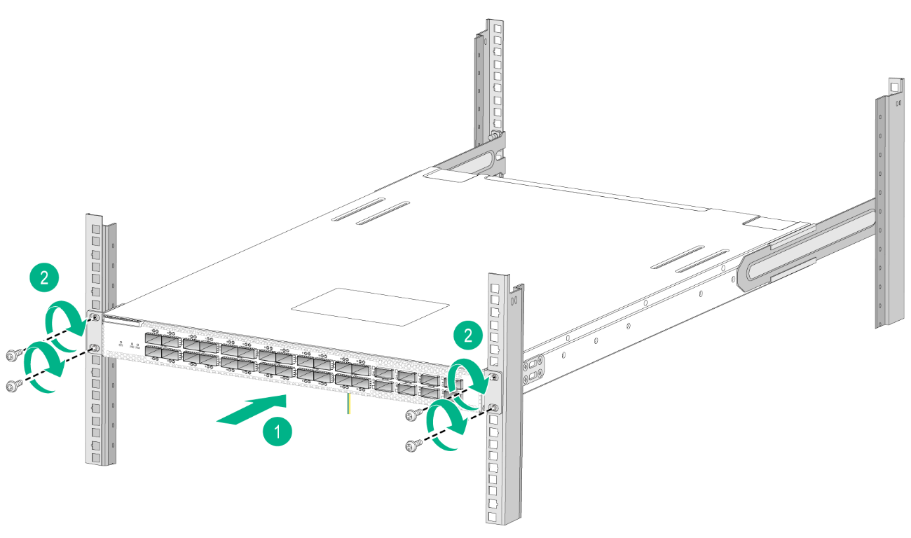
Figure2-22 Mounting an S9855-48CD8D/S9855-24B8D switch in the rack (mounting brackets installed at the power supply side)
Grounding the switch
|
|
WARNING! · Correctly connecting the grounding cable is crucial to lightning protection and EMI protection. Make sure you connect the grounding cable for the switch correctly. · Connect the grounding cable to the grounding system in the equipment room. Do not connect it to a fire main or lightning rod. |
|
|
CAUTION: · To guarantee the grounding effect, connect the switch to a grounding strip in the equipment room by using the grounding cable provided with the switch. · To protect the switch from lighting strikes, see H3C Network Devices Lighting Protection Guide. |
The power input end of the switch has a noise filter, whose central ground is directly connected to the chassis to form the chassis ground (commonly known as PGND). You must securely connect this chassis ground to the earth to minimize the potential for system damage, maximize the safety at the site, and minimize EMI susceptibility of the system.
You can ground a switch by using a grounding strip at the installation site.
To ground the switch by using a grounding strip:
1. Attach the two-hole grounding lug of the grounding cable to the grounding point on the chassis. For more information, see "Connecting the grounding cable to the switch."
2. Remove the hex nut of a grounding post on the grounding strip.
3. Attach the ring terminal at the other end of the grounding cable to the grounding post on the grounding strip, and use the hex nut to secure the ring terminal to the grounding post.
Figure2-23 Connecting the grounding cable to a grounding strip
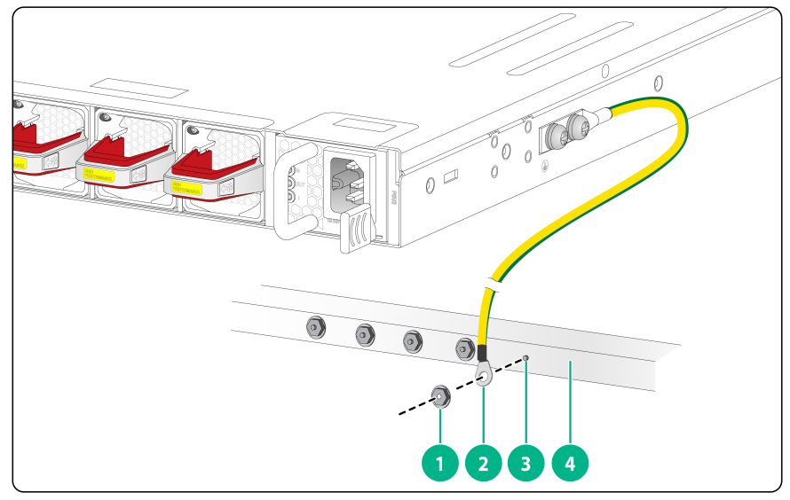
|
(1) Hex nut |
(2) Ring terminal |
|
(3) Grounding post |
(4) Grounding strip |
|
|
NOTE: The grounding terminal position in the figure is for illustration only. |
Installing/removing fan trays
|
|
CAUTION: The switch has multiple fan tray slots. For adequate heat dissipation, follow these guidelines: · The S9825-64D switch with the LS-S9825-64D product code came with the six fan tray slots empty. Before powering on the switch, make sure it fully configured with fan trays and the fan trays are the same model. · The S9825-64D switch with the LS-9825-64D-H1 product code came with the eight fan tray slots empty. When you install ZR or ZR+ modules in the two lower rows of ports on the switch, make sure all fan tray slots on the switch have fan trays installed. In other situations, you can install six fan trays in slots FAN3 to FAN8. · Make sure each slot has a module or filler panel installed when the switch is operating. · If multiple fan trays fail on the operating switch, do not remove the fan trays at the same time. Replace the fan trays one after another and finish replacing a fan tray within 3 minutes. |
Select fan trays compatible with the switch. For the optional fan trays and their specifications, see H3C S9825 & S9855 Switch Series Hardware Information and Specifications.
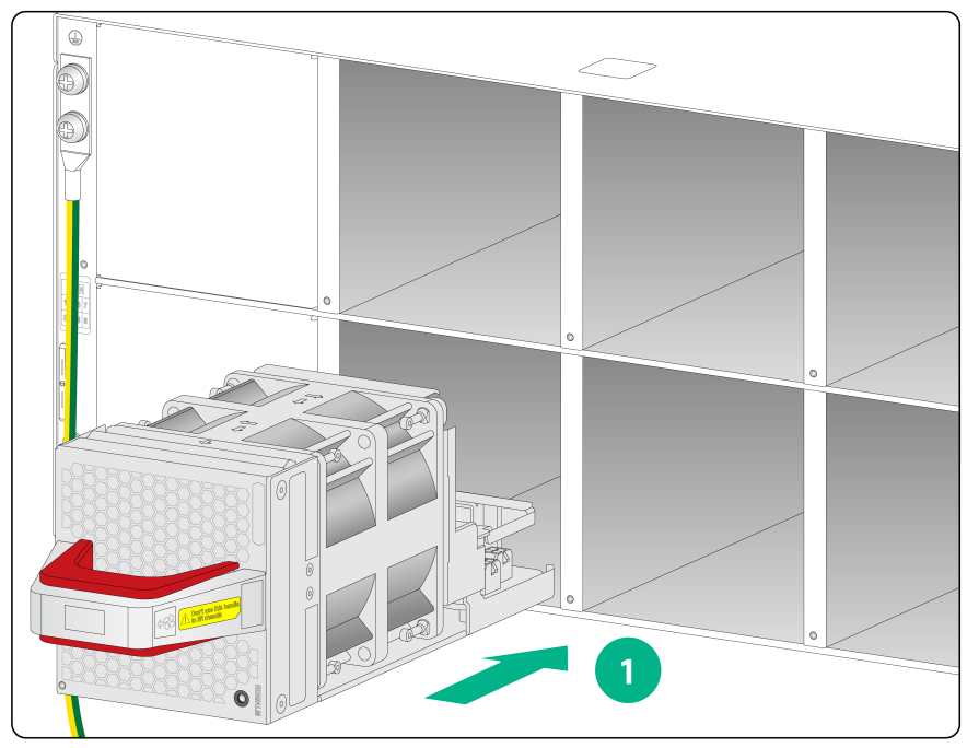
Installing a fan tray
|
|
CAUTION: To prevent damage to the fan tray or the connectors on the backplane, insert the fan tray gently. If you encounter a hard resistance while inserting the fan tray, pull out the fan tray and insert it again. |
To install a fan tray:
1. Wear an ESD wrist strap and make sure it makes good skin contact and is reliably grounded.
2. Unpack the fan tray and verify that the fan tray model is correct.
3. Orient the fan tray with the connector facing downwards. Pressing the red part of the handle with one hand and supporting the fan tray bottom with the other, slide the fan tray along the guide rails into the slot until the fan tray is fully seated in the slot and has a firm contact with the backplane.
Figure2-24 Installing a FAN-40B-1-C fan tray on an S9855-48CD8D/S9855-24B8D switch
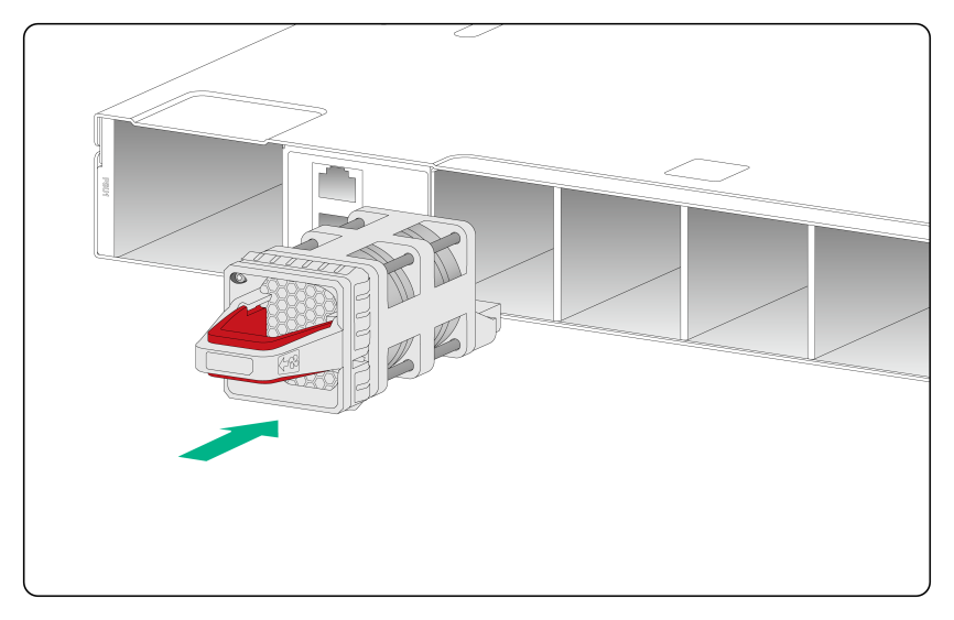
Figure2-25 Installing a FAN-80B-1-B fan tray on an S9825-64D switch
Removing a fan tray
|
|
WARNING! · Ensure electricity safety and never touch the rotating fans when you hot-swap a fan tray. · To prevent a fan from causing loud noise, do not touch the fan blades and rotation axis, even if the fan is not rotating. |
To remove a fan tray:
1. Wear an ESD wrist strap and make sure it makes good skin contact and is reliably grounded.
2. Orient the fan tray with the connector facing downwards. Pressing the red part of the handle with one hand, pull the fan tray part way out of the slot. Supporting the fan tray bottom with the other, pull the fan tray completely out of the slot along the guide rails.
3. Put the removed fan tray in an antistatic bag.
Figure2-26 Removing a FAN-40B-1-C fan tray
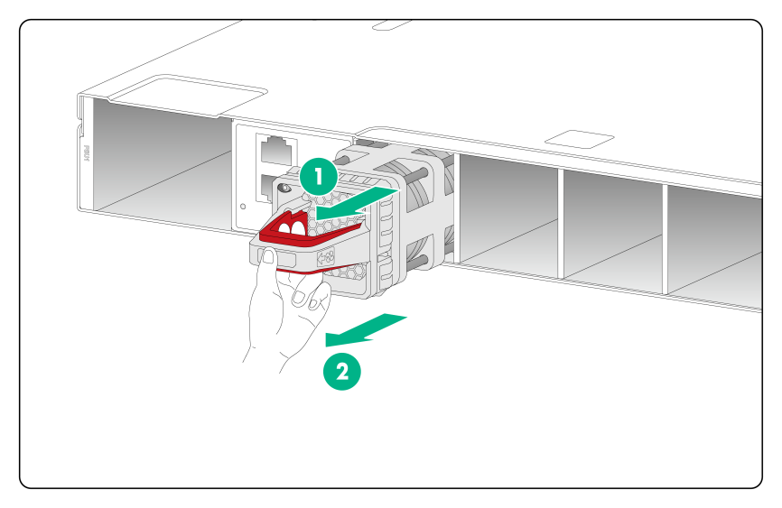
Figure2-27 Removing a FAN-80B-1-B fan tray
Installing and removing power supplies
|
|
WARNING! · To avoid bodily injury or device damage, strictly follow the procedures in Figure2-28 and Figure2-29 to install and remove a power supply. · Provide a separate circuit breaker for each power supply. |
|
|
CAUTION: Make sure each slot has a filler panel or module installed when the switch is operating. |
The S9855-48CD8D and S9855-24B8D switches each have two power supply slots. The switches came with power supply slot PSU1 empty and power supply slot PSU2 installed with a filler panel.
The S9825-64D switch has four power supply slots. It came with power supply slot PSU1 empty and power supply slots PSU2, PSU3, and PSU4 each installed with a filler panel.
The PSR1600C-12A-B power supply is available for the switch. For the specifications of the PSR1600C-12A-B power supply, see H3C S9825 & S9855 Switch Series Hardware Information and Specifications.
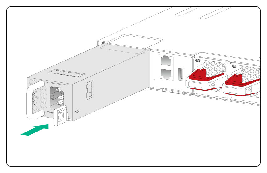
Figure2-28 Power supply installation procedure
![]()
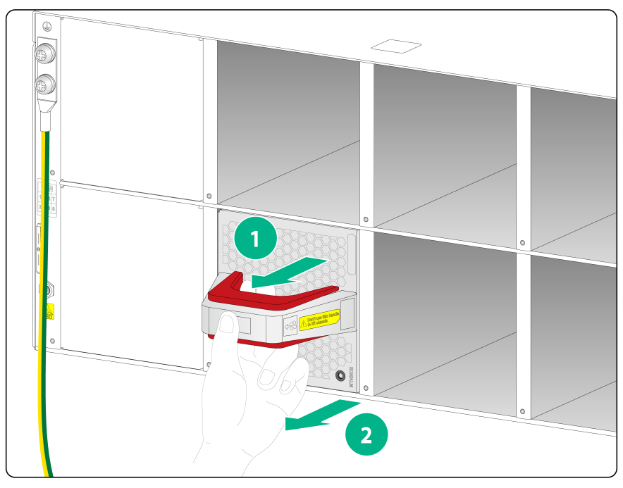
Figure2-29 Power supply removal procedure
![]()
Installing a power supply
The power supply installation procedure is the same for the switches. The S9855-48CD8D switch is used as an example in the following figures.
To install a power supply:
1. Wear an ESD wrist strap and make sure it makes good skin contact and is reliably grounded.
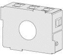
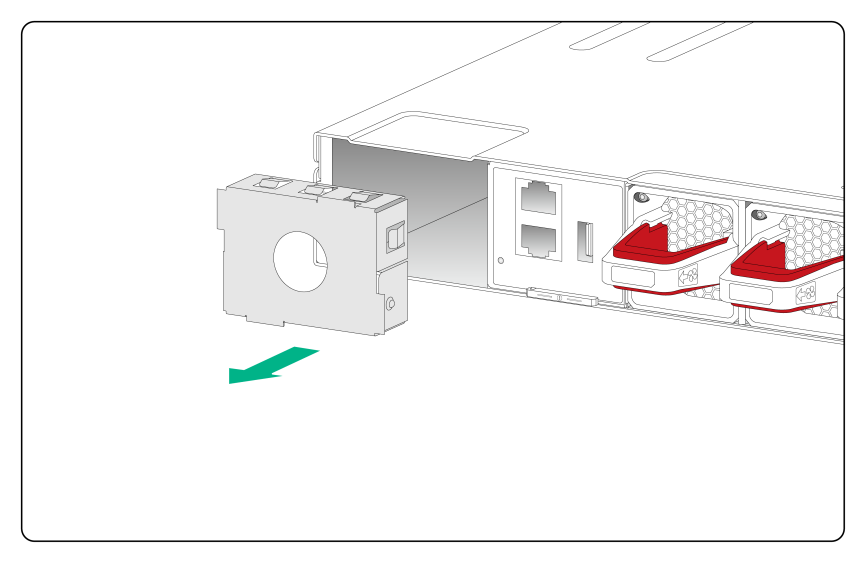
2. Remove the filler panel, if any, from the target power supply slot, as shown in Figure2-30.
Figure2-30 Removing the filler panel
3. Unpack the power supply and verify that the power supply model is correct.
4. Correctly orient the power supply with the lettering on it upward. Grasping the power supply handle with one hand and supporting the power supply bottom with the other, slide the power supply slowly into the slot along the guide rails. Make sure the power supply connectors have firm contact with the backplane.
|
|
CAUTION: The power supply and the slot form an anti-misalignment structure. If you insert the power supply into the slot upside down or the power supply is not aligned with the slot correctly, you will encounter a hard resistance. If this happens, pull out the power supply, orient it correctly, and then insert it again. Do not insert the power supply forcibly. |
Figure2-31 Installing a power supply
Removing a power supply
|
|
CAUTION: · When the S9855-48CD8D or S9855-48CD8D switch has two power supplies operating in 1+1 redundancy mode, removing one power supply does not affect the operation of the switch. When the switch has only one power supply present, removing the power supply causes power down of the switch. · When the S9825-64D switch has power supplies operating in 2+1 or 2+2 redundancy mode, removing one or two power supplies does not affect the operation of the switch. When the switch has only two power supplies present, removing power supply might cause power down of the switch or power insufficiency. |
The power supply removal procedure is the same for the switches. The S9855-48CD8D switch is used as an example in the following figures.
To remove a power supply:
1. Wear an ESD wrist strap and make sure it makes good skin contact and is reliably grounded.
2. Remove the power cord from the power supply.
3. As shown in Figure2-32, use one hand to hold the power supply handle, press the latch towards the handle, and then pull the power supply part way out of the slot. Supporting the power supply with the other hand, pull it completely out of the slot.
4. Put the removed power supply in an antistatic bag for future use.
5. If you are not to install a new power supply, install a filler panel in the slot to ensure good ventilation in the switch.
Figure2-32 Removing a power supply
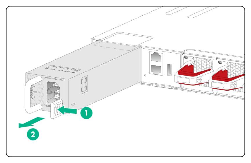
|
(1) Use the thumb to press the latch towards the handle |
(2) Pull the power supply out |
Connecting power cords
|
|
WARNING! · Make sure each power cord has a separate circuit breaker. · Before you connect a power cord, make sure the circuit breaker for the power cord is switched off. |
The switch uses PSR1600C-12A-B power supplies. To connect the AC power cord for a PSR1600C-12A-B power supply:
1. Insert the female connector of the AC power cord supplied with the power supply into the power receptacle on the power supply.
2. Use a releasable cable tie to secure the power cord to the handle of the power supply, as shown in Figure2-33.
3. Connect the other end of the power cord to an AC power source.
Figure2-33 Connecting the AC power cord for a PSR1600C-12A-B power supply
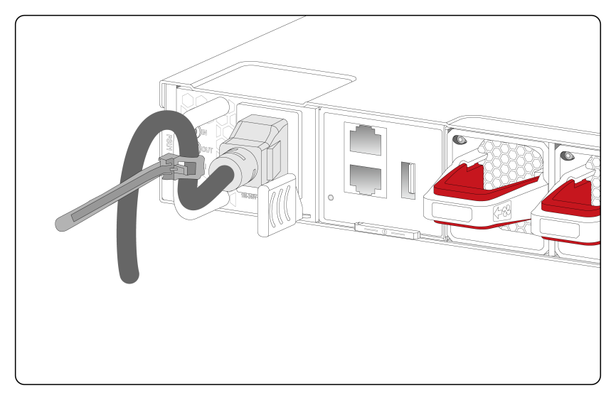
|
(1) Releasable cable tie |
|
(2) Lock the cable tie to secure the power cord to the handle of the power supply |
Verifying the installation
After you complete the installation, verify the following items:
· There is enough space around the switch for heat dissipation.
· The rack is sturdy and stable.
· The grounding cable is securely connected.
· The power supplies are as required by the switch.
· The power cords are correctly connected.
· To prevent signal ports from getting damaged by overvoltage or overcurrent caused by lightning strikes, route interface cables only indoors.
|
|
IMPORTANT: For information about how to protect the switch from lightning strikes, see H3C Network Devices Lightning Protection Guide. |
3 Accessing the switch for the first time
Connecting the switch to a configuration terminal
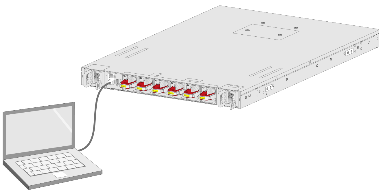
The switch came with a serial console cable. You can use the serial console cable to connect the serial console port on the switch to a configuration terminal.
In Figure3-1, the switch is connected to a configuration terminal (PC as an example) from the serial console port.
Figure3-1 Connecting the switch to a configuration terminal from the serial console port
Connecting the serial console cable
|
|
CAUTION: · Identify the mark on the serial console port and make sure you are connecting to the correct port. · The serial ports on PCs do not support hot swapping. To connect a PC to an operating switch, first connect the PC end. To disconnect a PC from an operating switch, first disconnect the switch end. |
A serial console cable is an 8-core cable, with a crimped RJ-45 connector at one end for connecting to the serial console port of the switch, and a DB-9 female connector at the other end for connecting to the serial port on the console terminal.
Figure3-2 Serial console cable
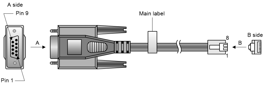
Table3-1 Console port signaling and pinout
|
RJ-45 |
Signal |
DB-9 |
Signal |
|
1 |
RTS |
8 |
CTS |
|
2 |
DTR |
6 |
DSR |
|
3 |
TXD |
2 |
RXD |
|
4 |
SG |
5 |
SG |
|
5 |
SG |
5 |
SG |
|
6 |
RXD |
3 |
TXD |
|
7 |
DSR |
4 |
DTR |
|
8 |
CTS |
7 |
RTS |
To connect the serial console port on the switch to a terminal (for example, a PC):
1. Plug the DB-9 female connector of the serial console cable to the serial port on the PC.
2. Connect the RJ-45 connector to the serial console port on the switch.
Setting terminal parameters
To configure and manage the switch through the console port, you must run a terminal emulator program, TeraTermPro or PuTTY, on your configuration terminal. You can use the emulator program to connect a network device, a Telnet site, or an SSH site. For more information about the terminal emulator programs, see the user guides for these programs
The following are the required terminal settings:
· Bits per second—9600.
· Data bits—8.
· Stop bits—1.
· Parity—None.
· Flow control—None.
Powering on the switch
1. Before powering on the switch, verify that the following conditions are met:
¡ All the fan tray slots have a fan tray installed.
¡ The power cords are connected correctly.
¡ The input power voltage is as required by the switch.
¡ The console cable is connected correctly.
¡ The configuration terminal (a PC, for example) has started, and its serial port settings are consistent with the console port settings on the switch.
2. Power on the switch.
During the startup process, you can access BootWare menus to perform tasks such as software upgrade and file management. The BootWare interface and menu options vary by software version. For more information about BootWare menu options, see the software-matching release notes for the device.
3. After the startup completes, you can access the CLI to configure the switch.
For more information about the configuration commands and CLI, see H3C S9825 & S9855 Switch Series Configuration Guides and H3C S9825 & S9855 Switch Series Command References.
4 Maintenance and troubleshooting
Power supply failure
Symptom
The status LED on a power supply is not steady green.
Solution
To resolve the issue:
1. Verify that the power cord is connected correctly.
2. Verify that the power source is as required by the switch.
3. Verify that the operating temperature of the switch is in the acceptable range and adequate ventilation is available for the power supply.
4. If the issue persists, contact H3C Support.
To replace a power supply, see "Installing and removing power supplies."
Fan tray failure
|
|
CAUTION: The switch has six fan tray slots. If multiple fan trays fail when the switch is operating, do not remove the fan trays at the same time. Replace the fan trays one after another and finish replacing a fan tray within 3 minutes. |
Symptom
The status LED on the fan tray is steady red and the system outputs a fan tray alarm message.
Solution
See "Installing/removing fan trays" to replace the fan tray. If the issue persists, contact H3C Support.
Configuration terminal display issues
No output
Symptom
The configuration terminal does not have any output when the switch is powered on.
Solution
To resolve the issue:
1. Verify that the power system is operating correctly.
2. Verify that the console cable is connected correctly.
3. Verify that the console cable does not have any problems and the terminal settings are correct.
4. If the issue persists, contact H3C Support.
Garbled output
Symptom
The output of the configuration terminal is garbled.
Solution
To resolve the issue:
1. Verify that configuration terminal settings are correct:
¡ Baud rate—9600.
¡ Data bits—8.
¡ Parity—None.
¡ Stop bits—1.
¡ Flow control—None.
