- Table of Contents
- Related Documents
-
| Title | Size | Download |
|---|---|---|
| 01-Text | 9.78 MB |
Contents
Entering the BIOS setup utility
Displaying processor information
Displaying onboard drive information
Displaying HDM network information
Setting HDM network information
Setting the system date and time
Restoring BIOS default settings
UEFI Variables Protection submenu
Serial Port Console Redirections submenu
PCI Subsystem Settings submenu
Miscellaneous Configuration submenu
AMD Mem Configuration Status submenu
About the BIOS
Introduction
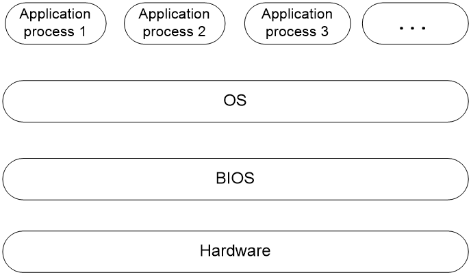
The Basic Input and Output System (BIOS) is a non-volatile firmware stored in the system ROM of a server. It is used to perform hardware initialization during server booting and provide runtime services for the operating systems. As shown in Figure 1, the BIOS interacts between the server hardware and the operating system (OS).
Figure 1 Layered architecture of a server system
Applicable products
This document is applicable to the following products:
· H3C UniServer R4950 G6
· H3C UniServer R5350 G6
Using this document
The information in this document is subject to change over time. You can access the H3C website to obtain the most recent version of the BIOS.
The information in this document might differ from your product if it contains custom configuration options or features.
The document describes the default graphic-mode BIOS.
Options on the BIOS screen vary by product or version and some options might be hidden and only used for internal debugging. To avoid impact on system operation, do not display or edit the hidden options without professional guidance.
Common BIOS tasks
This section provides procedures for the following common BIOS tasks:
· Entering the BIOS setup utility
· Displaying processor information
· Displaying memory information
· Displaying onboard drive information
· Displaying HDM network information
· Setting HDM network information
· Setting the system date and time
· Setting the server boot order
· Restoring BIOS default settings
Entering the BIOS setup utility
1. Connect a keyboard, a mouse, and a monitor to the server or enable the remote console from the HDM Web interface.
For information about enabling the remote console, see H3C Servers HDM User Guide.
2. Start or restart the server.
3. Press Del or Esc when the BIOS startup screen opens, as shown in Figure 2.

Table 1 Shortcut keys on the POST screen
|
Key |
Description |
|
Esc/Del |
Enter the BIOS setup screen. |
|
F7 |
Enter the Boot menu. |
|
F10 |
Enter the iFIST GUI. For more information, see H3C Servers iFIST User Guide. |
|
F12 |
Enter PXE boot. |
4. (Optional.) If you have set a BIOS administrator password and a user password, select the role before entering BIOS setup.
By default, no BIOS passwords are set. For information about BIOS password setup, see "Configuring BIOS passwords."
If you enter an incorrect password for three consecutive times, the server will restart automatically.
If you forget the password, use the system maintenance switch in the server to clear BIOS password settings. For more information about the system maintenance switch, see the user guide for the server.
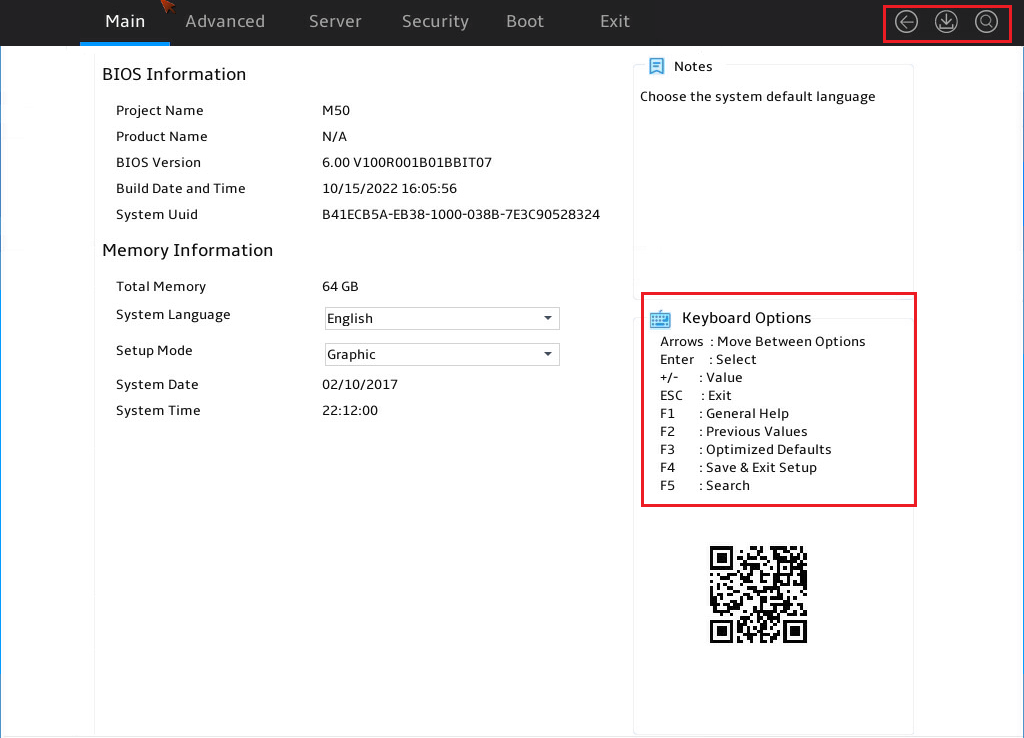
5. On the BIOS setup utility screen that opens, follow the instructions in lower right corner of the BIOS setup utility to configure BIOS settings, as shown in Figure 3.
Table 2 shows detailed information about the operation keys.
Figure 3 BIOS setup utility screen
|
Key |
Description |
|
→ ← |
Select a screen or item. |
|
↑ ↓ |
Select menu or option by navigating up or down. |
|
Enter |
Select an item to edit its value or access a submenu. |
|
+/- |
Change the field value of the selected item. |
|
ESC |
Exit the BIOS setup utility or return to the previous screen. |
|
F1 |
Display the general help window. |
|
F2 |
Load previous values in the BIOS. |
|
F3 |
Load default values in the BIOS. |
|
F4 |
Save the current configuration and exit the BIOS. |
|
F5 |
To find relevant options for a specific keyword, enter the keyword and press Enter to search for related results. |
|
<K> |
Scroll up the help information in the top-right corner of the interface. |
|
<M> |
Scroll down the help information in the top-right corner of the interface. |
|
|
Discard changes and exit. |
|
|
Save changes and exit. |
|
|
To find relevant options for a specific keyword, enter the keyword and press Enter to search for related results. |
Displaying processor information
1. Enter the BIOS setup utility. For more information, see "Entering the BIOS setup utility."
2. Select Advanced > CPU Configuration, and press Enter.
The Processor Configuration submenu opens, as shown in Figure 4.
Figure 4 CPU Configuration submenu screen

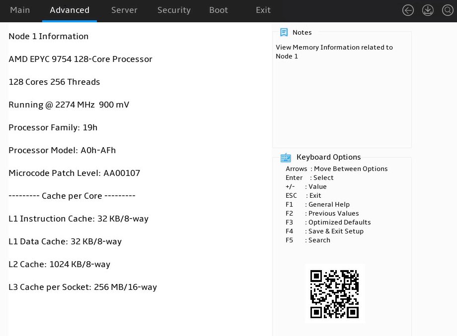
3. Select a CPU node. This example select node 1, as shown in Figure 5.
For more information, see "CPU Configuration submenu."
Figure 5 Node 1 Information submenu
Displaying memory information
1. Enter the BIOS setup utility. For more information, see "Entering the BIOS setup utility."
2. Select Advanced > North Bridge, as shown in Figure 6.
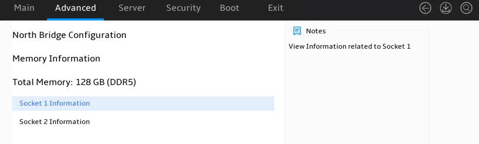
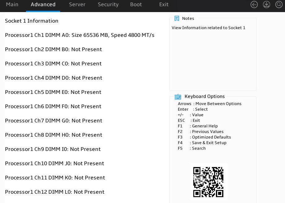
3. Select a processor, and press Enter, as shown in Figure 7. This example uses Socket 1 Information to display whether the DIMMs for the processor are installed, and the capacity and frequency information of these DIMMs.
For more information, see "North Bridge submenu."
Figure 7 Socket 1 Information submenu
Displaying onboard drive information
1. Enter the BIOS setup utility. For more information, see "Entering the BIOS setup utility."
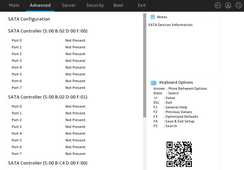
2. Select Advanced > SATA Configuration, and press Enter.
The SATA Configuration submenu that opens displays drive information, as shown in Figure 8.
Figure 8 SATA Configuration submenu
Displaying HDM network information
About this task
Perform this task to configure IP address settings of HDM dedicated and shared network ports, subnets, gateway addresses, and the method for obtaining the network information.
Procedure
1. Enter the BIOS setup utility. For more information, see "Entering the BIOS setup utility."
2. Select Server > HDM Network Configuration, and press Enter.
The HDM Network Configuration submenu opens, as shown in Figure 9.
Figure 9 HDM Network Configuration submenu

Setting HDM network information
About this task
Perform this task to configure both HDM dedicated and shared network ports, subnets, and the method for obtaining the network information.
Restrictions and guidelines
Do not disconnect the AC power within 15 seconds after you modify and save HDM IPv4 and IPv6 address settings. If you fail to do so, the IP address setting might fail.
To avoid network storms, make sure the IP address of the HDM shared network port is on a network segment different than the HDM dedicated network port.
To avoid device disconnection, make sure HDM network configurations are correct.
Procedure
1. Enter the BIOS setup utility. For more information, see "Entering the BIOS setup utility."
2. Select Server > HDM Network Configuration, and press Enter.
As shown in Figure 10, in the HDM Network Configuration submenu, both IPv4 configuration and IPv6 configuration are supported. Take IPv4 network configuration as an example.
3. Select IPv4 Network Configuration.
4. Select Configuration Address Source for HDM Dedicated Network Port, and press Enter.
5. In the dialog box that opens, select the method for obtaining HDM network information of HDM dedicated and shared network ports. Options are:
¡ Unspecified—Retains current configuration. This is the default.
¡ Static—Uses manually specified configuration.
¡ DynamicHdmDhcp—Uses network information obtained through DHCP.
6. As shown in Figure 10, perform the following steps:
¡ If you select Unspecified or DynamicHdmDhcp, press Enter.
¡ If you select Static, select the parameters, as shown in Table 3. In the dialog box that opens, configure the parameters as needed, and then press Enter.
|
|
IMPORTANT: If you select Static for configuring HDM network information, you must enter the station IP address. If you fail to do so, the IP address of HDM will be set to the default of 0.0.0.0. |
Figure 10 HDM Network Configuration submenu
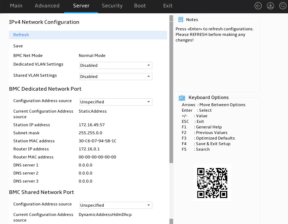
Table 3 Items on the HDM Network Configuration submenu screen
|
Item |
Description |
Remarks |
|
Station IP Address |
N/A |
Required |
|
Subnet Mask |
Subnet mask for the static IP address. |
Required |
|
Router IP Address |
IP address of the gateway. |
Optional |
7. Click Save to save the configuration, and then click Refresh. The configruation will take effect immediately.
Configuring BIOS passwords
About this task
BIOS passwords include a boot password, an administrator password, a user password, and a drive password for BIOS Setup. By default, no passwords are set.
· A boot password is required each time the server starts up.
· An administrator password or a user password is required each time you enter the BIOS Setup screen.
If only the administrator password is set, you can enter this password to obtain administrator privileges. The system prompts for the password when you use shortcut keys to enter the BIOS setup utility, iFIST, boot menu, or PXE boot interface.
If only the user password is set, you can enter this password to obtain user privileges. Table 4 shows the menu items that are accessible in the BIOS with the user privileges.
Table 4 BIOS menu items accessible with the user password
|
Level-1 menu |
Submenu items |
|
Server |
IPv4/IPv6 Network Configuration > Refresh |
|
Security |
User Password |
|
Exit |
Save Changes and Exit |
|
Discard Changes and Exit |
|
|
Save Changes and Reset |
|
|
Discard Changes and Reset |
|
|
Save Changes |
|
|
Discard Changes |
Restrictions and guidelines
When you change a BIOS password, make sure the new password is different from the most recent three passwords.
The BIOS passwords must meet the following requirements:
· A case-sensitive string of 8 to 20 characters. Valid characters are letters, digits, spaces, and special characters in Table 5.
· Contain a minimum of two character types from uppercase letters, lowercase letters, and digits.
· Contain a minimum of one space or special character.
|
Character name |
Symbol |
Character name |
Symbol |
|
Back quote |
` |
Tilde |
~ |
|
Exclamation point |
! |
At sign |
@ |
|
Pound sign |
# |
Dollar sign |
$ |
|
Percent sign |
% |
Caret |
^ |
|
Ampersand sign |
& |
Asterisk |
* |
|
Left parenthesis |
( |
Right parenthesis |
) |
|
Underscore |
_ |
Plus sign |
+ |
|
Minus sign |
- |
Equal sign |
= |
|
Left bracket |
[ |
Right bracket |
] |
|
Back slash |
\ |
Left brace |
{ |
|
Right brace |
} |
Vertical bar |
| |
|
Semi-colon |
; |
Apostrophe |
' |
|
Colon |
: |
Quotation marks |
" |
|
Comma |
, |
Dot |
. |
|
Forward slash |
/ |
Left angle bracket |
< |
|
Right angle bracket |
> |
Question mark |
? |
Setting a BIOS password
The procedure is the same for setting the administrator password and the user password. This section uses the administrator password as an example.
|
|
NOTE: As a best practice, configure the administrator password when you configure the user password. |
To set the administrator password:
1. Enter the BIOS setup utility. For more information, see "Entering the BIOS setup utility."
2. Select Security > Administrator Password, and press Enter.
3. As shown in Figure 11, in the dialog box that opens, enter an administrator password. The password must meet the requirements in "Restrictions and guidelines." Then, press Enter.
Figure 11 Setting the administrator password
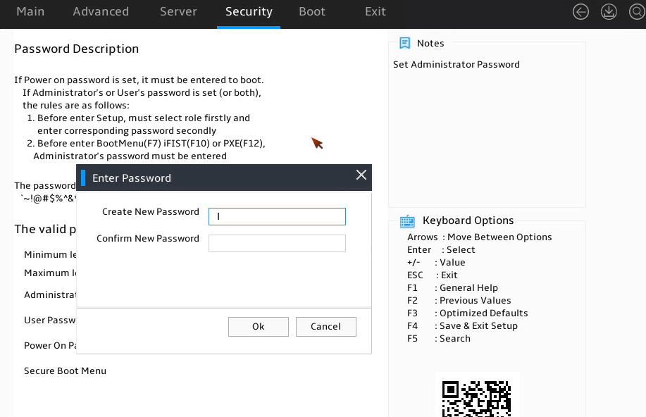
4. Confirm the password and press Enter.
5. Press F4 and Enter. The server will continue running. The BIOS password will be required upon the next startup of the server.
Deleting a BIOS password
The procedure is the same for deleting the administrator password and the user password. This section uses the administrator password as an example.
To delete the administrator password:
1. Enter the BIOS setup utility. For more information, see "Entering the BIOS setup utility."
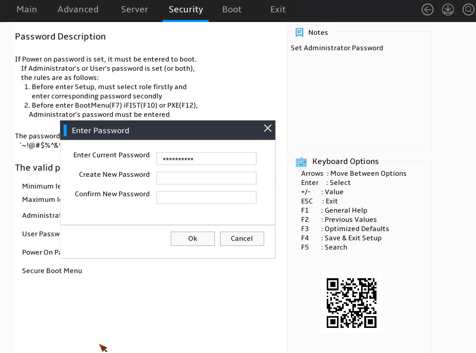
2. Select Security > Administrator Password -Installed, and press Enter, as shown in Figure 12.
3. In the Enter Password dialog box that opens, enter the current administrator password, leave the new password fields empty, select Ok, and then press Enter, as shown in Figure 12.
Figure 12 Deleting the administrator password
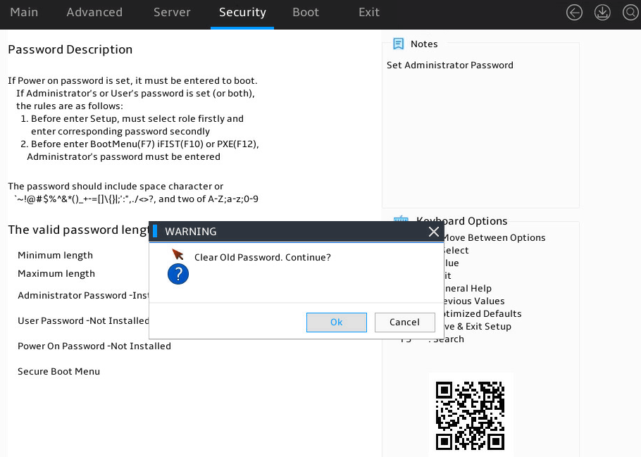
4. In the WARNING dialog box that opens, select Ok, and press Enter, as shown in Figure 13.
Figure 13 Confirming the deletion
5. Press F4. In the dialog box that opens, click Ok to save the configuration and exit the BIOS setup utility.
Setting the system date and time
1. Enter the BIOS setup utility. For more information, see "Entering the BIOS setup utility."
2. Select the Main menu.
Figure 14 Main menu
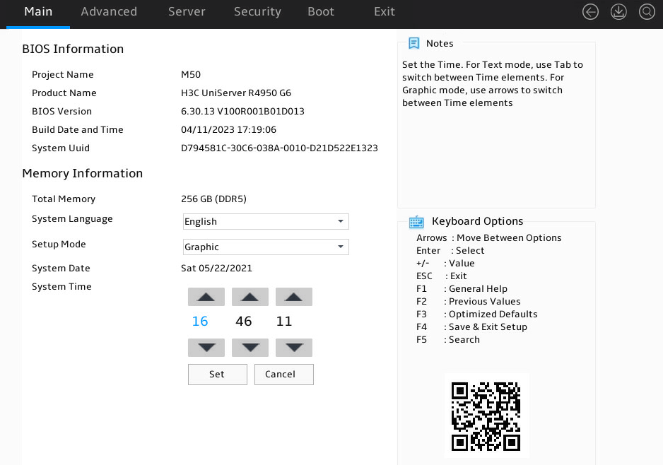
3. Set the system time, as shown in Figure 15:
a. Select System Time.
The system time uses the 24-hour time system and is in the format of hh:mm:ss.
b. Press → or ← to switch between the hour, minute, and second fields and then use the following methods to modify the value:
- Press + or ↑ to increase the value by 1.
- Press – or ↓ to decrease the value by 1.
c. To save the configuration, press → or ← to select the Set button, and then press Enter.
Figure 15 Setting the system time
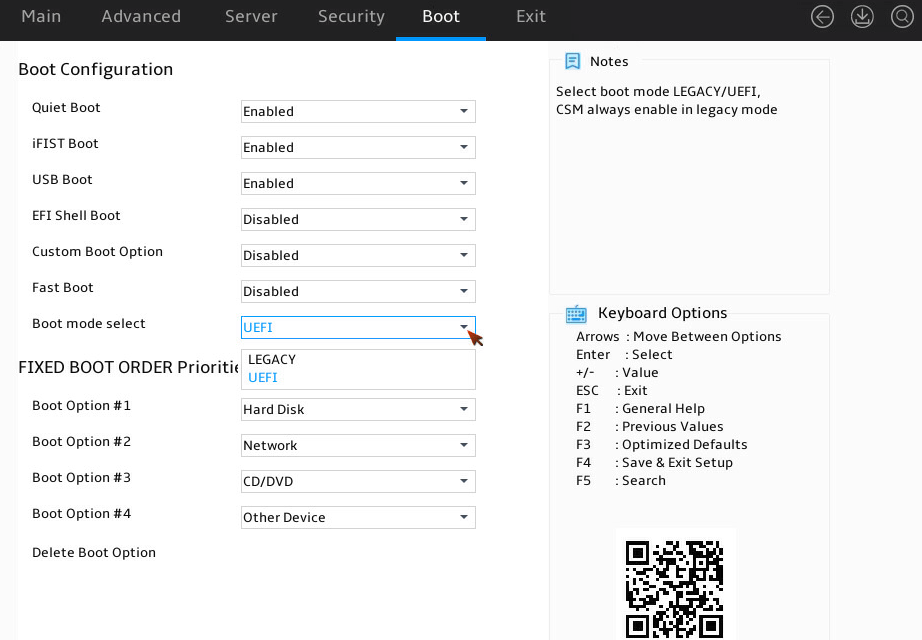
Setting the BIOS boot mode
About this task
The server supports two BIOS boot modes: legacy mode and UEFI mode.
By default, the boot mode is UEFI. For operating systems that support only the legacy mode, change the boot mode to legacy.
Restrictions and guidelines
An operating system can run only in the BIOS boot mode under which the system was installed. For example, operating systems installed in legacy mode cannot start up in UEFI mode, and operating systems installed in UEFI mode cannot start up in legacy mode.
The UEFI mode is not supported in an 32-bit operating system. You can install an operating system in Legacy mode. Only operating systems that support UEFI mode can be installed in UEFI mode.
Procedure
1. Enter the BIOS setup screen. For more information, see "Entering the BIOS setup utility."
2. As shown in Figure 16, select Boot > Boot mode select, and press Enter.
3. Select LEGACY or UEFI, and press Enter.
Figure 16 Setting the BIOS boot mode
4. Press F4 and Enter to save the configuration. The server will restart automatically.
Setting the server boot order
About this task
Perform this task to change the server boot order.
The default boot order is as shown in Figure 17. The Fixed Boot Order Priorities submenu lists the server boot order.
Restrictions and guidelines
If the server has more than one boot devices of the same type, the Fixed Boot Order Priorities list displays only the first boot device. To change the first boot device, enter the corresponding priorities submenu of the boot device, and then set the first boot option. For example, to change the first boot option for hard disks, enter the UEFI Hard Disk Drive BBS Priorities submenu as shown in Table 91Figure 109, and then set the first boot option.
Procedure
1. Enter the BIOS setup utility. For more information, see "Entering the BIOS setup utility."
2. As shown in Figure 17, select the Boot menu.
Figure 17 Boot menu

|
Item |
Example |
|
Hard Disk |
Disk (including virtual drives), SD cards, and USB-HDD. |
|
Network |
Network. |
|
CD/DVD |
CD-ROM and DVD-ROM (including virtual ones), USB-CD, and USB-DVD. |
|
Other Device |
The options include but are not limited to: · Boot option for entering UEFI Shell. This option is available only when EFI Shell Boot is set to Enabled. · USB devices whose capacity is less than 32 GB. |
|
Disabled |
The boot option is disabled. |
3. As shown in Figure 17, select the option to be modified from the Fixed Boot Order Priorities area, and press Enter.
4. Press F4 and Enter to save the configuration. The server will restart automatically.
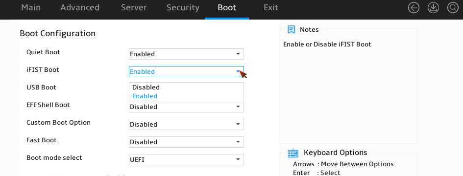
Enabling or disabling iFIST
About this task
This feature enables or disables iFIST. The integrated Fast Intelligent Scalable Toolkit (iFIST) is a standalone intelligent deployment tool embedded in the server. Users do not need to install it. For more information about the iFIST, see H3C Servers iFIST User Guide.
If iFIST is enabled, after the server is initialized, you can enter the iFIST system from the BIOS. If iFIST is disabled, the iFIST Boot shortcut will not be displayed on the BIOS set utility, and you cannot start iFIST by pressing F10.
Procedure
1. Enter the BIOS setup utility. For more information, see "Entering the BIOS setup utility."
2. Select Boot > iFIST Boot, select Enabled or Disabled, and then press Enter, as shown in Figure 18.
Figure 18 iFIST boot option
3. Press F4, and then select Ok to save the configuration and exit the BIOS utility.
The configuration takes effect after the server reboots.
Logging in to iFIST
Press F10 on the BIOS boot screen to access the iFIST GUI. iFIST login screen opens after iFIST starts up.
If the boot screen does not display the iFIST shortcut, make sure iFIST is enabled. For more information, see "Enabling or disabling iFIST."
Figure 19 BIOS boot screen

Configuring RAID
About this task
In modern data centers, servers play a crucial role in data storage. As servers evolve, they support an increasing number of hard drives. Building RAID for hard drives maximizes their advantages, making them easy to manage, providing fault tolerance, and enhancing reliability.
Procedure
For more information about configuring RAID, see H3C Servers Storage Controller User Guide.
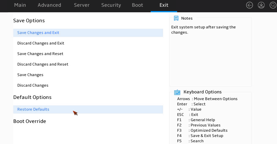
Restoring BIOS default settings
About this task
You can perform this task to restore BIOS to its default settings if unknown modifications to the BIOS cause system problems.
Procedure
1. Enter the BIOS setup utility. For more information, see "Entering the BIOS setup utility."
2. Press F3 in the BIOS, or select Exit > Restore Defaults and press Enter as shown in Figure 20.
3. Press F4 and Enter to save the settings. The configuration will take effect after the server reboots.
Figure 20 Restoring the default from the Exit submenu screen
BIOS menus
Main menu
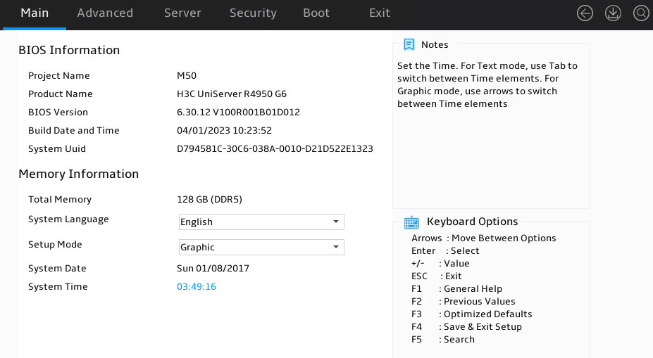
As shown in Figure 21, the Main menu contains information about the BIOS, memory, system language, and system time and date. For more information about the menu items, see Table 7.
Figure 21 Main menu screen
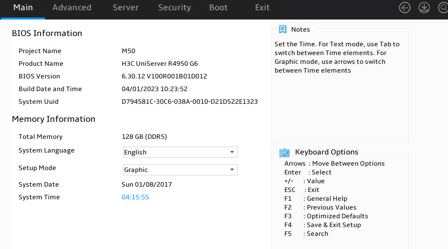
Table 7 Items on the Main menu screen
|
Item |
Description |
Default |
|
BIOS Information |
||
|
Project Name |
Displays the project name. |
N/A |
|
Product Name |
Displays the product name. |
N/A |
|
BIOS Version |
Displays the BIOS version. |
N/A |
|
Build Date and Time |
Displays the compiling date and time of the BIOS build. |
N/A |
|
System Uuid |
Displays the UUID of the system. |
N/A |
|
Memory Information |
||
|
Total Memory |
Displays the total memory capacity of DIMMs in GB and the DIMM type (for example, DRAM). |
N/A |
|
System Language |
Displays the language used in the system. The BIOS supports English and simplified Chinese. To switch between the languages, press Enter. |
English |
|
Setup Mode |
Set the BIOS setup mode. Options: · Text. · Graphic. |
Graphic |
|
System Date |
Displays the system date. You can change the system date as needed. The system date is in the format of mm/dd/yyyy. Click Date to make changes. Adjust the values using the arrows. Click Set to modify the date, or click Cancel to undo the modifications. · Press + or ↑ to increase the value by 1. · Press - or ↓ to decrease the value by 1. · Press → or ← to select other items to modify the value. |
N/A |
|
System Time |
Displays the system time. You can change the system time as needed. The system time is in the format of hh:mm:ss in 24-hour format. Click Time to make changes, adjust values using arrows, and click Set to apply modifies or Cancel to undo them. · Press + or ↑ to increase the value by 1. · Press - or ↓ to decrease the value by 1. · Press → or ← to select other items to modify the value. |
N/A |
Advanced menu
As shown in Figure 22, the Advanced menu contains advanced system features and functionalities, which are described in Table 8.
Figure 22 Advanced menu screen

Table 8 Items on the Advanced menu screen
|
Item |
Description |
|
AMD CBS |
Submenu for configuring CPU-related settings. |
|
AMD PBS |
Submenu for configuring AMD PBS settings. |
|
Trusted Computing |
Submenu for configuring trusted computing |
|
PSP Firmware Versions |
Submenu for viewing firmware version of Platform Security Processor (PSP). |
|
ACPI Settings |
Submenu for configuring Advanced Configuration and Power Interface (ACPI). |
|
UEFI Variables Protection |
Submenu for UEFI variables protection. |
|
Serial Port Console Redirection |
Submenu for configuring serial port console redirection. |
|
CPU Configuration |
Submenu for configuring CPUS. |
|
North Bridge |
Submenu for configuring north bridge. |
|
PCI Subsystem Settings |
Submenu for configuring the PCI subsystem. |
|
USB Configuration |
Submenu for configuring USB. |
|
CSM Configuration |
Submenu for configuring the compatibility support module (CSM). |
|
NVMe Configuration |
Submenu for configuring NVMe. |
|
SATA Configuration |
Submenu for configuring SATA devices. |
|
Network Configuration |
Submenu for configuring network stacks. |
|
Miscellaneous Configuration |
Other configuration. |
|
SMBIOS Configuration |
Submenu for configuring SMBIOS. |
|
AMD Mem Configuration Status |
Submenu for viewing AMD memory configuration status. |
|
Slot 16: BROADCOM<MegaRAID 9560-8i 4GB>Configuration Utility-07.21.05.00 (Example) |
Submenu for configuring the installed storage controllers. |
|
Driver Health |
Submenu for viewing the health status of the installed drivers. |
|
|
NOTE: For options like AMD CBS and AMD PBS in the BIOS, you need to have a prior understanding of their functions and impacts. Changes should be made with caution to avoid any potential effects on system startup, performance, and power consumption. |
AMD CBS submenu
Figure 23 shows the AMD CBS menu screen, on which you can configure CPU-related settings as described in Table 9.
Figure 23 AMD CBS submenu screen
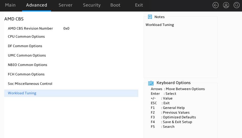
Table 9 Items on the AMD CBS submenu screen
|
Item |
Description |
|
AMD CBS Revision Number |
Revision number of AMD CBS. |
|
CPU Common Options |
Submenu for configuring common CPU settings. |
|
DF Common Options |
Submenu for configuring common Data Fabric (DF) settings. |
|
UMC Common Options |
Submenu for configuring common Unified Memory Controllers (UMC) settings. |
|
NBIO Common Options |
Submenu for configuring common NorthBridge IO (NBIO) settings. |
|
FCH Common Options |
Submenu for configuring common Server/Fusion Controller Hub (FCH) settings. |
|
Soc Miscellaneous Control |
Submenu for configuring Soc miscellaneous control settings. |
|
Workload Tuning |
Submenu for configuring workload tuning settings. |
CPU Common Options submenu
Figure 24 shows the CPU Common Options submenu screen, on which you can configure features such as hyper-threading and threading control for CPUs.
Figure 24 CPU Common Options submenu
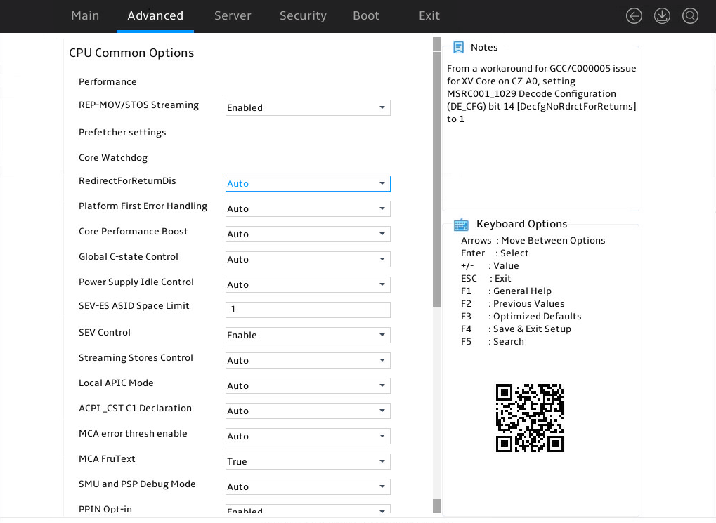
Table 10 Items on the CPU Common Options submenu screen
|
Item |
Description |
|
Performance |
Submenu for configuring CPU performance settings. |
|
REP-MOV/STOS Streaming |
Select whether to enable REP-MOV/STOS to use non-cached streaming storage to provide larger capacity. Options: · Enabled (default). · Disabled. |
|
Prefetcher settings |
Submenu for configuring CPU prefetcher settings. |
|
Core Watchdog |
Submenu for configuring core watchdog settings. |
|
RedirectForReturnDis |
Select whether to return to Dis redirection. Options: · Auto (default). · 0. · 1. |
|
Platform First Error Handling |
Select whether to enable platform first error handling (PFEH). Options: · Auto (default). · Enabled. · Disabled. |
|
Core Performance Boost |
Select whether to enable core performance boost. Options: · Auto (default). · Disabled. |
|
Global C-state Control |
Select whether to enable CPUs to operate in C-state power saving mode. This feature enables CPUs to automatically adjust its power state, voltage, frequency, and power consumption according to the actual situation. Options: · Auto (default). · Enabled—Allows a CPU to enter low-consumption state to save power. However, this can increase memory latency and frequency jitter. · Disabled. |
|
Power Supply Idle Control |
Select the option to control power supply in idle state. Options: · Auto (default). · Low Current Idle—Provides low current in idle state. · Typical Current Idle—Provides typical current in idle state. |
|
SEV-ES ASID Space Limit |
Specify the ASID space limit for Secure Encrypted Virtualization (SEV-ES). The default is 1. |
|
SEV Control |
Select whether to enable SEV control. Options: · Enabled (default). · Disabled. |
|
Streaming Stores Control |
Select whether to enable streaming stores control. Options: · Auto (default). · Enabled. · Disable. |
|
Local APIC Mode |
Select a mode for local advanced programmable interrupt controller (APIC). Options: · Auto (default)—The mode is automatically set to xAPIC. If the total number of processor cores exceeds 256, the mode automatically changes to x2APIC. · xAPIC. · x2APIC—This mode helps OSs run more efficiently on high core count configurations and optimizes interrupt distribution in a virtualized environment. · Compatibility. |
|
ACPI_CST C1 Declaration |
Select whether to make the C1 state available for OSs. Options: · Auto (default). · Enabled—Makes the C1 state available for OSs. · Disabled—Makes the C1 state unavailable for OSs. |
|
ACPI_CST C2 Latency |
Set the C2 state latency. The default is 800. |
|
MCA error thresh enable |
Select whether to enable MCA error thresholding. Options: · Auto (default)—Disables MCA error thresholding. · False—Disables MCA error thresholding. · True—Enables MCA error thresholding. |
|
MCA error thresh count |
This item is available only when MCA error thresh enable is set to True. Set the MCA error threshold in hexadecimal notation. The default is FF5. |
|
MCA FruText |
MCA text value. Options: · True (default). · False. |
|
SMU and PSP Debug Mode |
Select whether to enable SMU and PSP debug mode. Options: · Auto. · Enabled. · Disabled (default). |
|
PPIN Opt-in |
Select whether to enable Protected Processor Identification Number (PPIN). Options: · Enabled (default). · Disabled. · Auto. |
|
SNP Memory(RMP Table) Coverage |
Select whether to enable secure nested paging (SNP) memory coverage. Options: · Auto (default). · Enabled (default). · Disabled. · Custom—Customizes the SNP memory coverage mode. When this options is selected, the Amount of Memory to Cover and Split RMP Table items are available. |
|
Amount of Memory to Cover |
This item is available only when SNP Memory(RMP Table) Coverage is set to Custom. Specify the total amount of the memory to cover. The default is 2000. |
|
Split RMP Table |
Select whether to enable Reverse Map Table (RMP) Options: · Auto (default). · Enabled. · Disabled. |
|
SMEE |
Select whether to enable AMD encryption, including Secure Memory Encryption (SME) and Secure Encrypted Virtualization (SEV). Options: · Enabled. · Disabled. · Auto (default). |
|
Action on BIST Failure |
Select the action to be taken upon BIST failure. Options: · Auto (default). · Do nothing—No action is taken. · Down-CCD—Disable CCD. |
|
Fast Short REP MOVSB (FSRM) |
Select whether to enable Fast Short REP MOVSB (FSRM). Options: · Auto (default). · Enabled. · Disabled. |
|
Enhanced REP MOBSB/STOSB(ERSM) |
Select whether to enable Enhanced REP MOBSB/STOSB(ERSM). Options: · Auto (default). · Enabled. · Disabled. |
|
Log Transparent Errors |
Select whether to enable log transparent errors. Options: · Auto (default). · Enabled. · Disabled. |
|
AVX512 |
Select whether to enable Advanced Vector Extensions (lAVX512). Options: · Auto (default). · Enabled. · Disabled. |
|
MONITOR and MWAIT disable |
Select whether to enable the disabling of MONITOR and MWAIT. Enabling MONITOR and MWAIT allows you to monitor CPU status and optimize instruction execution. Enabling this option might allow certain OSs to independently adjust power-saving options. Options: · Auto (default). · Enabled—Disables MONITOR/MWAIT. · Disabled—Enables MONITOR/MWAIT. |
|
Small Hammer Configuration |
Select whether to enable Small Hammer configuration. Options: · Auto (default). · Enabled. · Disabled. |
|
Corrector Branch Predictor |
Select whether to enable corrector branch predictor. Options: · Enabled. · Disabled. |
|
PAUSE Delay |
Specify the number of cycles for pause delay. Options: · Auto (default). · Disabled—Disables · 16 cycles. · 32 cycles. · 64 cycles. · 128 cycles. |
|
CPU Speculative Stroe Modes |
Select a CPU speculative stroe mode. Opions: · Auto (default). · Balanced. · More Speculative. · Less Speculative. |
Performance submenu
Figure 25 shows Performance submenu screen. The submenu items are described in Table 11.
Figure 25 Performance submenu screen
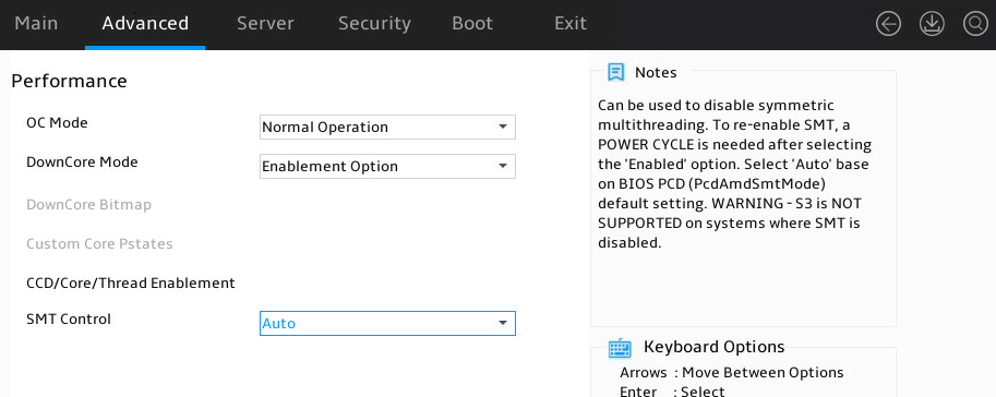
Table 11 Items on the Performance submenu screen
|
Item |
Description |
|
OC Mode |
Select the overclock settings. Options: · Normal Operation (default)—Uses common settings. · Customized—Uses custom settings. |
|
Custom Core Pstates |
Submenu for configuring custom core P-states options. |
|
CCD/Core/Thread Enablement |
Submenu for configuring CCD/core/thread enablement options. |
|
SMT Control |
Select whether to enable Symmetric Multi-Threading (SMT) control. Options: · Enabled. · Disabled. · Auto (default). |
The warning screen as shown in Figure 26 opens. The submenu items are described in Table 12.
Figure 26 Warning screen for access to Custom Core Pstates submenu
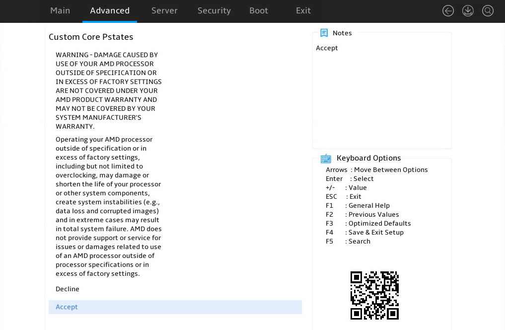
Table 12 Items on the warning screen for access to the Custom Core Pstates submenu
|
Item |
Description |
|
Accept |
Acknowledge the warning message and access the Custom Core Pstates submenu. |
Figure 27 shows Custom Core Pstates submenu screen. The submenu items are described in Table 13.
Core P-states indicate the operating performance states that feature the combination of core frequencies and voltages. Processors support a maximum of three core P-states available for OSs, including Pstate0 (basic frequency), Pstate1 (medium frequency), and Pstate2 (minimum frequency).
Figure 27 Custom Core Pstates submenu screen
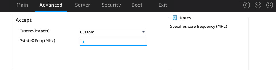
Table 13 Items on the Custom Core Pstates submenu screen
|
Item |
Description |
|
Custom Pstate0 |
Select whether to enable customizing Pstate0 settings. Options: · Custom—Allows you to customize Pstate0 settings. · Auto (default). |
|
Pstate0 Freq (MHz) |
This item is available only when Custom Pstate0 is set to Custom. Set the Pstate0 core frequency. The default varies by CPU model. |
Figure 28 shows CCD/Core/Thread Enablement submenu screen. The submenu items are described in Table 14.
Figure 28 CCD/Core/Thread Enablement submenu screen
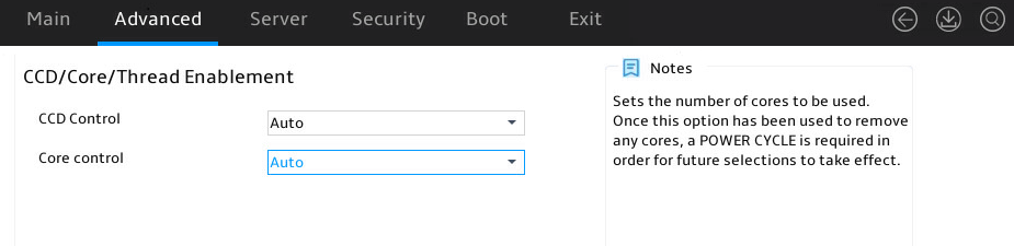
Table 14 Items on the CCD/Core/Thread Enablement submenu screen
|
Item |
Description |
|
CCD Control |
Specify the number of CCDs that are activated. Options: · Auto (default). · 2 CCDS/4 CCDS/6 CCDS/8CCDS/10CCDS—Speicfies the corresponding number of CCDs. |
|
Core Control |
Set the number of cores to be used. Options: · Auto (default). · X (X+0)—Specifies X cores. The value range for X depends on the CPU model. |
Prefetcher Settings submenu
Figure 29 shows Prefetcher Settings submenu screen. The submenu items are described in Table 15.
Figure 29 Prefetcher Settings submenu screen
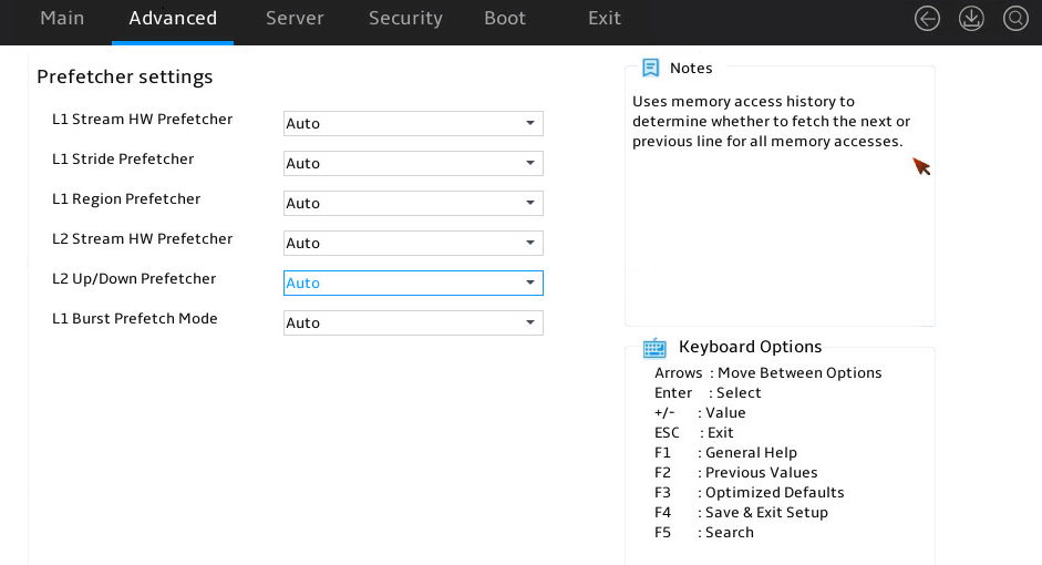
Table 15 Items on the Prefetcher Settings submenu screen
|
Description |
|
|
L1 Stream HW Prefetcher |
Select whether to enable the level-1 stream hardware prefetcher. Options: · Auto (default). · Disabled. · Enabled. |
|
L1 Stride Prefetcher |
Select whether to enable the level-1 stride prefecther, which prefetches a fixed length each time based on memory access history. Options: · Auto (default). · Disabled. · Enabled. |
|
L1 Region Prefetcher |
Select whether to enable the level-1 region prefecther, which is based on data access. Options: · Auto (default). · Disabled. · Enabled. |
|
L2 Stream HW Prefetcher |
Select whether to enable the level-2 stream hardware prefetcher. Options: · Auto (default). · Disabled. · Enabled. |
|
L2 Up/Down Prefetcher |
Select whether to enable using memory access history to determine whether to fetch the next or previous line for all memory accesses. Options: · Auto (default). · Disabled. · Enabled. |
|
L1 Burst Prefetch Mode |
Select whether to enable the level-1 burst prefetch mode. Options: · Auto (default). · Disabled. · Enabled. |
Core Watchdog submenu
The items on the Core Watchdog submenu are described in Table 16.
Table 16 Items on the Core Watchdog submenu screen
|
Item |
Description |
|
Core Watchdog Timer Enable |
Select whether to enable core watchdog timer. Options: · Auto (default). · Disabled. · Enabled. |
|
Core Watchdog Timer Severity |
Specify the severity of the core watchdog timer. · Auto (default). · No Error. · Transparent. · Corrected. · Deferred. · Uncorrected. · Fatal. |
DF Common Options submenu
Figure 30 shows the DF Common Options submenu screen, on which you can configure features such as DRAM scrub time, memory interleaving, and link speed.
The submenu items are described in Table 17.
Figure 30 DF Common Options submenu screen
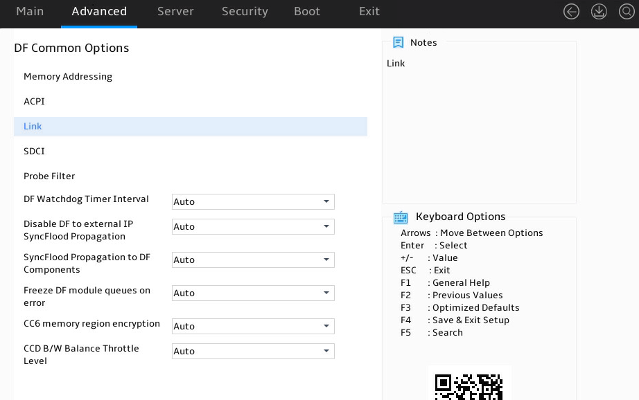
Table 17 Items on the DF Common Options submenu screen
|
Item |
Description |
|
Memory Addressing |
Submenu for memory addressing configuration. |
|
ACPI |
Submenu for configuring ACPI. |
|
Link |
Submenu for link speed configuration. |
|
SDCI |
Submenu for configuring Smart Data Cache Injection (SDCI). |
|
Probe Filter |
Submenu for configuring probe filter. |
|
DF Watchdog Timer Interval |
Specify the Data Fabric watchdog timer interval. Options: · Auto (default). · 41ms/166ms/334ms/669ms/1.34s/2.68s/5.36s—Select an interval. |
|
Disable DF to external IP SyncFlood Propagation |
Select whether to enable disable external IP synchronous flooding propagation. Options: · Auto (default). · Syncflood enabled—Enables synchronous flooding. · Syncflood disabled—Disables synchronous flooding. |
|
SyncFlood Propagation to DF Components |
Select whether to enable synchronous flooding propagation of DF components. Options: · Auto (default). · Syncflood enabled—Enables synchronous flooding. · Syncflood disabled—Disables synchronous flooding. |
|
Freeze DF module queues on error |
Select whether to freeze DF module queues upon errors. Options: · Auto (default). · Disabled—Does not freeze DF module queues upon errors. · Enabled—Freezes DF module queues upon errors. |
|
CC6 memory region encryption |
Select whether to enable CC6 memory region encryption. Data in memory cannot be read without authorization. Options: · Auto (default). · Disabled. · Enabled. |
|
CCD B/W Balance Throttle Level |
Set the CCD B/W balance throttle level. Options: · Auto (default). · level 0 to 4. |
Memory Addressing submenu
Figure 31 shows Memory Addressing submenu screen. The submenu items are described in Table 18.
Figure 31 Memory Addressing submenu screen
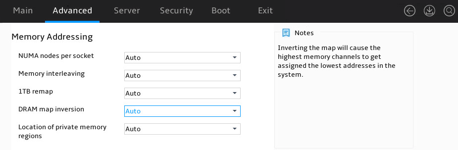
Table 18 Items on the Memory Addressing submenu screen
|
Item |
Description |
|
NUMA nodes per socket |
Specify the number of desired NUMA nodes per socket (NPS). Options: · NPS0. · NPS1. · NPS2. · NPS4. · Auto (default)—NPS1. |
|
Memory interleaving |
Select whether to enable memory interleaving. Enabling memory interleaving can map the physical addresses of DIMMs to different memory channels, improving memory access speed. However, for memory-sensitive services, memory interleaving might cause performance degradation. Options: · Auto (default). · Enabled. · Disabled—If this feature is disabled, the configuration of the NUMA nodes per socket parameter does not take effect. |
|
1TB remap |
Configure 1TB remapping. Options: · Auto (default). · Do not remap. · Attempt to remap. |
|
DRAM map inversion |
Select whether to enable DRAM map inversion to improving system parallelism. Options: · Auto (default). · Disabled. · Enabled. |
|
Location of private memory regions |
Select the distribution method of private memory regions. Options: · Auto (default). · Distributed. · Consolidated. |
ACPI submenu
Figure 32 shows the ACPI submenu screen. The submenu items are described in Table 19.
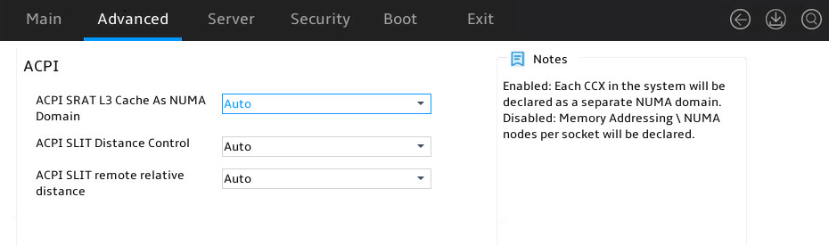
Table 19 Items on the ACPI submenu screen
|
Item |
Description |
|
ACPI SRAT L3 Cache As NUMA Domain |
Select whether to enable ACPI Static Resource Affinity Table (SRAT) to consider L3 cache as NUMA. Options: · Auto (default). · Disabled. · Enabled. |
|
ACPI SLIT Distance Control |
Set ACPI system locality info table (SLIT) distance control. Options: · Auto (default). · Manual. If you select this option, The following options and default values are displayed: ¡ ACPI SLIT same socket distance: 12 ¡ ACPI SLIT remote socket distance: 32 |
|
ACPI SLIT remote relative distance |
Set the ACPI SLIT remote relative distance. Options: · Auto (default). · Near. · Far. |
Link submenu
Figure 33 shows the Link submenu screen. The submenu items are described in Table 20.
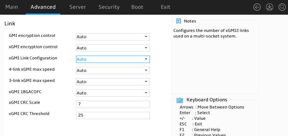
Table 20 Items on the Link submenu screen
|
Item |
Description |
|
GMI encryption control |
Select whether to enable GMI encryption control. Options: · Auto (default). · Disabled. · Enabled. |
|
xGMI encryption control |
Select whether to enable xGMI encryption control. Options: · Auto (default). · Disabled. · Enabled. |
|
xGMI Link Configuration |
Set the number of xGMI links. Options: · Auto (default). · 3 xGMI Links. · 4 xGMI Links. · 2 xGMI Links + 2 PCI Links. |
|
4-link xGMI max speed |
Set the maximum rate of 4-link xGMI Options: · 12Gbps to 32Gbps. · Auto (default). |
|
3-link xGMI max speed |
Set the maximum rate of 3-link xGMI. Options: · 12Gbps to 32Gbps. · Auto (default). |
|
xGMI 18GACOFC |
Select whether to enable xGMI 18GACOFC. Options: · Auto (default). · Disabled. · Enabled. |
|
xGMI CRC Scale |
Set the xGMI Cyclic Redundancy Check (CRC) scale. The default is 5. |
|
xGMI CRC Threshold |
Set the xGMI CRC threshold. The default is 25. |
SDCI submenu
Figure 34 shows the SDCI submenu screen. The submenu items are described in Table 21.
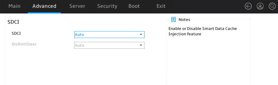
Table 21 Items on the SDCI submenu screen
|
Item |
Description |
|
SDCI |
Select whether to enable SDCI. Options: · Auto (default). · Disabled. · Enabled. |
|
DisRmtSteer |
This item is available only when SCDI is set to Enabled. Select whether to enable DisRmtSteer. Options: · Auto (default). · Disabled. · Enabled. |
Probe Filter submenu
Figure 35 shows the Probe Filter submenu screen. The submenu items are described in Table 22.
Figure 35 Probe Filter submenu screen
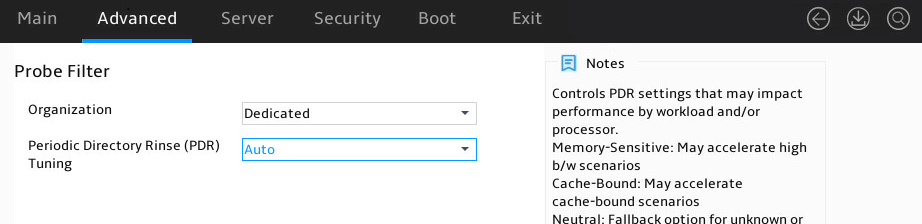
Table 22 Items on the Probe Filter submenu screen
|
Item |
Description |
|
Organization |
Select whether to allow multiple memory/CXL channels to share probes. If the memory space is over 16 TB, this item will be automatically set to Shared. Options: · Auto. · Dedicated (default)—Does not allow probe sharing. · Shared—Allows probe sharing. |
|
Periodic Directory Rinse (PDR) Tuning |
Select a PDR tuning option, which might impact performance by workload and/or processor. Options: · Auto (default). · Memory-Sensitive—Might accelerate high b/w scenarios. · Cache-Bound—Might accelerate cache-bound scenarios. · Neutral—Provides real-time response for unknown or mixed mode. |
UMC Common Options submenu
Figure 36 shows the UMC Common Options submenu screen, on which you can view and configure memory mapping information. The submenu items are described in Figure 37.
Figure 36 UMC Common Options submenu screen
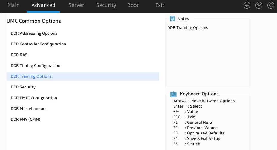
Figure 37 Items on the UMC Common Options submenu screen
|
Item |
Description |
|
DDR Addressing Options |
Submenu for configuring the DDR addressing settings. |
|
DDR Controller Configuration |
Submenu for configuring the DDR controller settings. |
|
DDR RAS |
Submenu for configuring the DDR RAS settings. |
|
DDR Timing Configuration |
Submenu for configuring the DDR timing settings. |
|
DDR Training Options |
Submenu for configuring the DDR training settings. |
|
DDR Security |
Submenu for configuring the DDR security settings. |
|
DDR PMIC Configuration |
Submenu for configuring the DDR PMIC settings. |
|
DDR Miscellaneous |
Submenu for configuring the DDR miscellaneous settings. |
|
DDR PHY(CMN) |
Submenu for configuring the DDR PHY (CMN) settings. |
DDR Addressing Options submenu
Figure 38 shows the DDR Addressing Options submenu screen. The submenu items are described in Table 23
Figure 38 DDR Addressing Options submenu screen
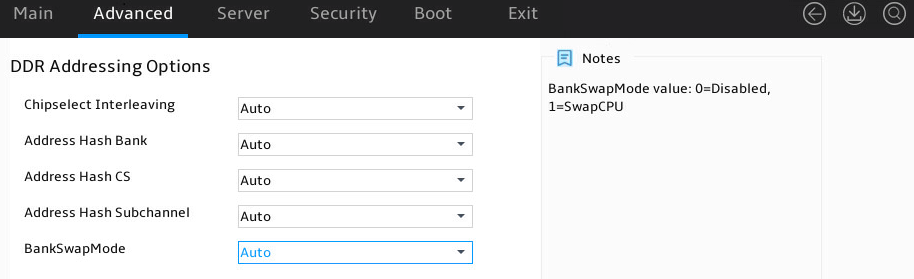
Table 23 Items on the DDR Addressing Options submenu screen
|
Item |
Description |
|
Chipselect Interleaving |
Select whether to enable chipselect interleaving. Options are: · Disabled. · Auto (default). |
|
Address Hash Bank |
Select whether to enable address hash bank. Options are: · Disabled. · Enabled. · Auto (default). |
|
Address Hash CS |
Select whether to enable address hash CS. Options are: · Auto (default). · Enabled. · Disabled. |
|
Address Hash Subchannel |
Select whether to enable address hash subchannel. Options are: · Auto (default). · Enabled. · Disabled. |
|
BankSwapMode |
Select the bank swap mode. Options are: · Auto (default). · Disabled. · Swap CPU. |
DDR Controller Configuration submenu
Figure 39 shows the DDR Controller Configuration submenu screen. The submenu items are described in Table 24.
Figure 39 DDR Controller Configuration submenu screen
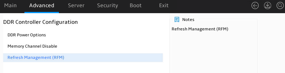
Table 24 Items on the DDR Controller Configuration submenu screen
|
Item |
Description |
|
DDR Power Options |
Submenu for configuring DDR power settings. |
|
Memory Channel Disable |
Submenu for enabling or disabling memory channels. |
|
Refresh Management(RFM) |
Submenu for configuring RFM settings. |
DDR Power Options submenu
Figure 40 shows the DDR Power Options submenu screen. The submenu items are described in Table 25.
Figure 40 DDR Power Options submenu screen

Table 25 Items on the DDR Power Options submenu screen
|
Item |
Description |
|
Power Down Enable |
Select whether to enable the power down feature. Options are: · Disabled. · Enabled. · Auto (default). |
|
Sub Urgent Refresh Lower Bound |
Set the sub-urgent refresh lower bound. The default is 1. |
|
Urgent Refresh Limit |
Set the urgent refresh limit. The default is 4. |
|
DRAM Refresh Rate |
Set the DRAM refresh rate. Options are: · 3.9 usec (default). · 1.5 usec. |
|
Self-Refresh Exit Staggering |
Set the self-refresh exit staggering. Options are: · Disabled. · n = 1 to n = 9 (default) |
Memory Channel Disable submenu
Figure 41 shows the Memory Channel Disable submenu screen. The submenu items are described in Table 26.
Figure 41 Memory Channel Disable submenu screen
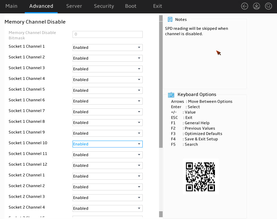
Table 26 Items on the memory Channel Disable submenu screen
|
Item |
Description |
|
Memory Channel Disable Bitmask |
Set the memory channel disable bitmask. The default is 0. |
|
Socket X Channel Y |
Select whether to enable the channel. Options are: · Disabled. · Enabled (default). |
Refresh Management(RFM) submenu
Figure 42 shows the Refresh Management(RFM) submenu screen. The submenu items are described in Table 27.
Figure 42 Refresh Management(RFM) submenu screen
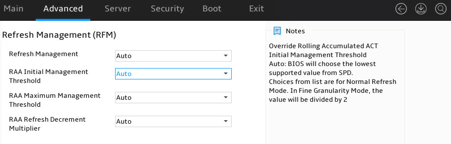
Table 27 Items on the Refresh Management(RFM) submenu screen
|
Item |
Description |
|
Refresh Management |
Select whether to enable refresh management (RFM). Options are: · Disabled. · Enabled. · Force Enabled. · Auto (default). ABL selects the optimal setting. |
|
RAA Initial Management Threshold |
Set the RAA initial management threshold. Options are: · 32. · 40. · 48. · 56. · 64. · 72. · 80. · Auto (default). ABL selects the lowest value from the DIMM SPD. |
|
RAA Maximum Management Threshold |
Set the RAA maximum management threshold. Options are: · Auto (default). ABL selects the lowest supported value from the DIMM SPD. · 3X. · 4X. · 5X. · 6X. |
|
RAA Refresh Decrement Multiplier |
Select the RAA refresh decrement multiplier. Options are: · Auto (default). ABL selects the optimal setting. · 0.5. · 1. |
DDR RAS submenu
Figure 43 shows the DDR RAS submenu screen. The submenu items are described in Table 28.
Figure 43 DDR RAS submenu screen
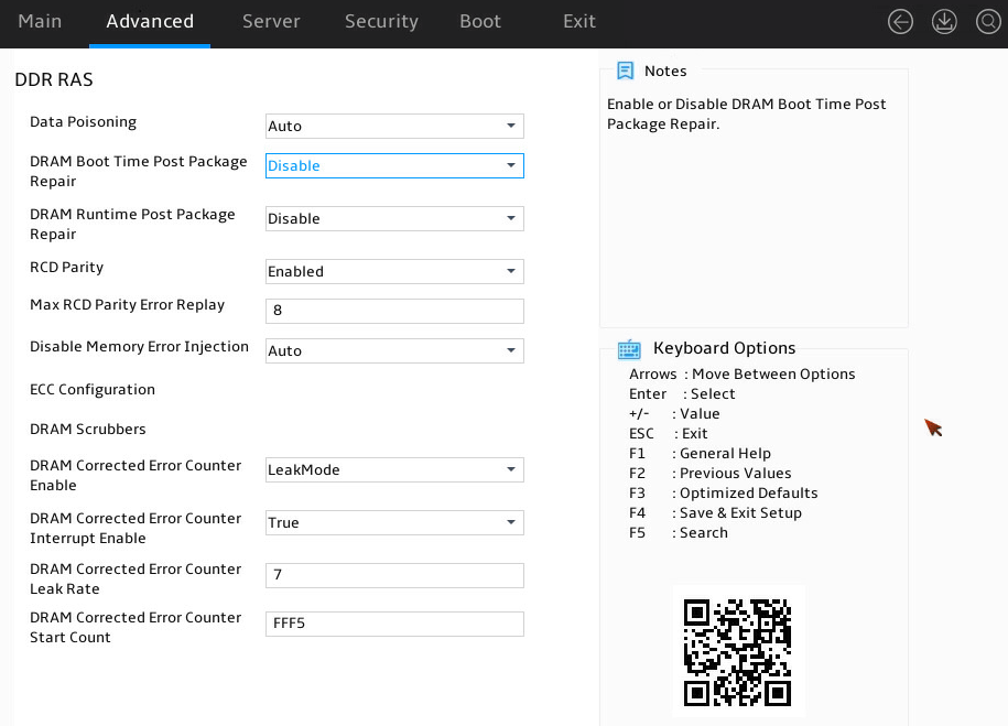
Table 28 Items on the DDR RAS submenu screen
|
Item |
Description |
|
Data Poisoning |
Select whether to label data as "bad data" when an uncorrectable error is detected in that data and then forward it to the target. Options are: · Disabled. · Enabled. · Auto (default). |
|
DRAM Boot Time Post Package Repair |
Select whether to enable DRAM post package repair at the boot time. Options are: · Disabled (default). · Enabled. |
|
DRAM Runtime Post Package Repair |
Select whether to enable DRAM runtime post package repair. Options are: · Enabled. · Disabled (default). |
|
RCD Parity |
Select whether to enable RCD parity check. Options are: · Auto. · Enabled. · Disabled. |
|
Max RCD Parity Error Replay |
Set the maximum number of RCD address parity check retries. The default is 8. |
|
Disable Memory Error Injection |
Select whether to disable memory error injection. Options are: · Auto (default). · True—Disable memory error injection. · False—Enable memory error injection. |
|
ECC Configuration |
Submenu for configuring ECC. |
|
DRAM Scrubbers |
Submenu for configuring DRAM scrubbing. |
|
DRAM Corrected Error Counter Enable |
Select whether to enable DRAM corrected error counter. Options are: · Disabled. · NoLeakMode. · LeakMode (default). |
|
DRAM Corrected Error Counter Interrupt Enable |
Select whether to enable DRAM corrected error counter interrupt. SMI is allowed during counting. Options are: · True (default)—Enable DRAM corrected error counter interrupt. · False—Disable DRAM corrected error counter interrupt. |
|
DRAM Corrected Error Counter Leak Rate |
Set the DRAM corrected error counter leak rate. The default is 7. |
|
DRAM Corrected Error Counter Start Count |
Set the DRAM corrected error counter start value. The default is FFF5. |
ECC Configuration submenu
Figure 44 shows the ECC Configuration submenu screen. The submenu items are described in Table 29.
Figure 44 ECC Configuration submenu screen
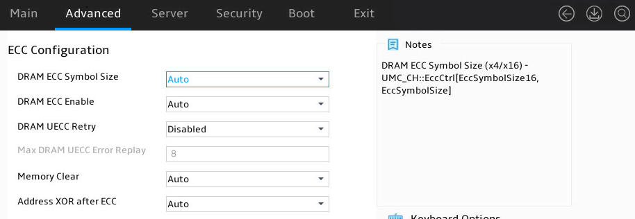
Table 29 Items on the ECC Configuration submenu screen
|
Item |
Description |
|
DRAM ECC Symbol Size |
Select the DRAM ECC symbol size. Options are: · Auto (default). · x4. · x16. |
|
DRAM ECC Enable |
Select whether to enable DRAM ECC. Options are: · Auto (default). · Disabled. · Enabled. |
|
DRAM UECC Retry |
Select whether to enable DRAM UECC retry. Options are: · Auto. · Disabled (default). · Enabled. |
|
Max DRAM UECC Error Replay |
This item is available only when the DRAM UECC Retry item is set to Enabled. Set the maximum number of UECC retries. The default is 8. |
|
Memory Clear |
Select whether to enable memory clearing. Options are: · Auto (default). · Disabled. · Enabled. |
|
Address XOR after ECC |
Select whether to enable post-ECC address XOR. Options are: · Auto (default). · Disabled. · Enabled. |
DRAM Scrubbers submenu
Figure 45 shows the DRAM Scrubbers submenu screen. The submenu items are described in Table 30.
Figure 45 DRAM Scrubbers submenu screen
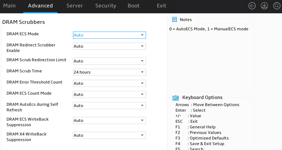
Table 30 Items on the DRAM Scrubbers submenu screen
|
Item |
Description |
|
DRAM ECS Mode |
Select a DRAM ECS mode. Options are: · AutomaticECS. · ManualECS. · Auto (default). · DisableECS. |
|
DRAM Redirect Scrubber Enable |
Select whether to enable DRAM redirection scrubbing. Options are: · Disabled. · Enabled. · Auto (default). |
|
DRAM Scrub Redirection Limit |
Select the maximum number of DRAM scrubs with redirection. Options are: · 8 Scrubs. · 4 Scrubs. · 2 Scrubs. · 1 Scrub. · Auto (default). |
|
DRAM Scrub Time |
Set the memory scrubbing duration. Options are: · Disabled. · 1 hour. · 4 hours. · 6 hours. · 8 hours. · 12 hours. · 16 hours. · 24 hours (default). · 48 hours. |
|
DRAM Error Threshold Count |
Set the DRAM error threshold count. Options are: · ETC_4. · ETC_16. · ETC_64. · ETC_256. · ETC_1024. · ETC_4096. · Auto (default). |
|
DRAM ECS Count Mode |
Select the DRAM ECS count mode. Options are: · Row Count Mode. · Code Word Count Mode. · Auto (default). |
|
DRAM AutoEcs during Self Refresh |
Select whether to enable AutoEcs during DRAM self-refreshing. Options are: · AutoEcs Disabled. · AutoEcs Enabled. · Auto (default). |
|
DRAM ECS WriteBack Suppression |
Select whether to enable DRAM ECS writeback suppression. Options are: · Disabled. · Enabled. · Auto (default). |
|
DRAM X4 WriteBack Suppression |
Select whether to enable DRAM X4 writeback suppression. Options are: · Disabled. · Enabled. · Auto (default). |
DDR Bus Configuration submenu
Figure 46 shows the DDR Bus Configuration submenu screen. The submenu items are described in Table 31.
Figure 46 DDR Bus Configuration submenu screen
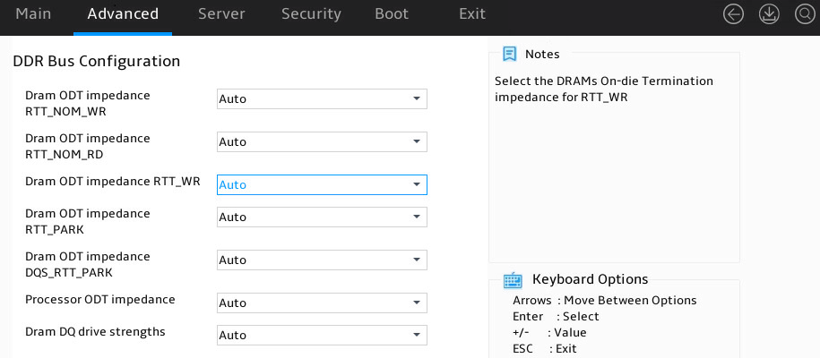
Table 31 Items on the DDR Bus Configuration submenu screen items
|
Item |
Description |
|
Dram ODT impedance RTT_NOM_WR |
Options are: · Auto (default). · RTT_OFF. · RZQ(240). · RZQ/2(120). · RZQ/3(80). · RZQ/4(60). · RZQ/5(48). · RZQ/6(40). · RZQ/7(34). |
|
Dram ODT impedance RTT_NOM_RD |
Options are: · Auto (default). · RTT_OFF. · RZQ(240). · RZQ/2(120). · RZQ/3(80). · RZQ/4(60). · RZQ/5(48). · RZQ/6(40). · RZQ/7(34). |
|
Dram ODT impedance RTT_WR |
Options are: · Auto (default). · RTT_OFF. · RZQ(240). · RZQ/2(120). · RZQ/3(80). · RZQ/4(60). · RZQ/5(48). · RZQ/6(40). · RZQ/7(34). |
|
Dram ODT impedance RTT_PARK |
Options are: · Auto (default). · RTT_OFF. · RZQ(240). · RZQ/2(120). · RZQ/3(80). · RZQ/4(60). · RZQ/5(48). · RZQ/6(40). · RZQ/7(34). |
|
Dram ODT impedance DQS_RTT_PARK |
Options are: · Auto (default). · RTT_OFF. · RZQ(240). · RZQ/2(120). · RZQ/3(80). · RZQ/4(60). · RZQ/5(48). · RZQ/6(40). · RZQ/7(34). |
|
Processor ODT impedance |
Options are: · Auto (default). · High Impedance. · 480 ohm. · 240 ohm. · 160 ohm. · 120 ohm. · 96 ohm. · 80 ohm. · 68.6 ohm. · 60 ohm. |
|
Dram DQ drive strengths |
Options are: · Auto (default). · 48 ohm. · 40 ohm. · 34 ohm. |
DDR Timing Configuration submenu
Figure 47 and Figure 48 show the DDR Timing Configuration submenu screen. The submenu items are described in Table 32.
Figure 47 DDR Timing Configuration submenu screen (1)
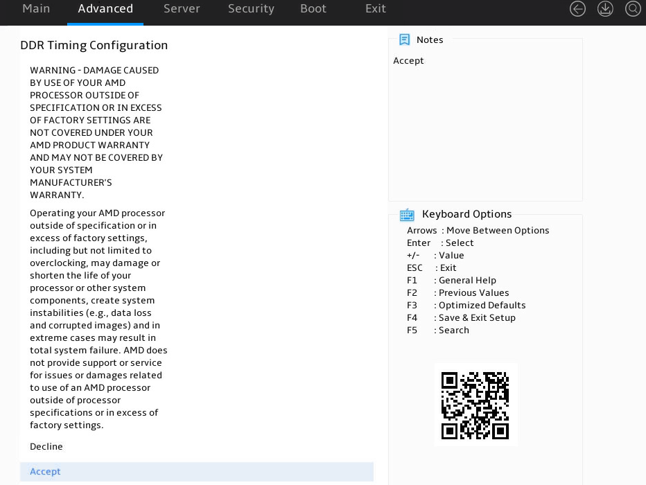
Figure 48 DDR Timing Configuration submenu screen (2)
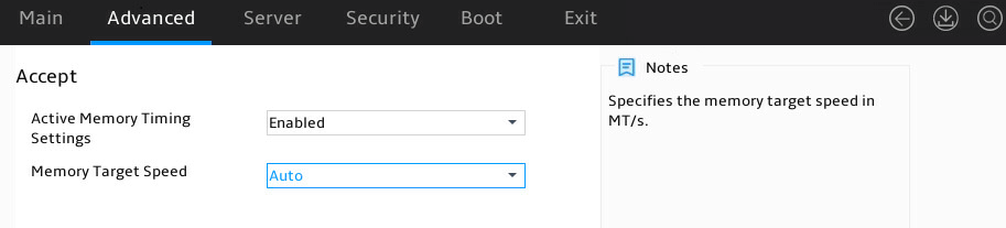
Table 32 Items on the DDR Timing Configuration submenu screen
|
Item |
Description |
|
Accept |
Click Accept on the DDR Time Configuration page to access the configuration menu. |
|
Active Memory Timing Setting |
Whether to enable memory timing. Options are: · Auto. · Enabled (default). |
|
Memory Target Speed |
Set the memory speed. Options are: · Auto (default). · DDR 3200. · DDR 3600. · DDR 4000. · DDR 4400. · DDR 4800. |
DDR Training Options submenu
Figure 49 shows the DDR Training Options submenu screen. The submenu items are described in Table 33.
Figure 49 DDR Training Options submenu screen
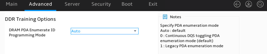
Table 33 Items on the DDR Training Options submenu screen
|
Item |
Description |
|
DRAM PDA Enumerate ID Programming Mode |
Select the DRAM PDA enumerate ID programming mode. Options are: · Auto (default). · Toggling PDA enumeration Mode. · Legacy PDA enumeration Mode. |
DDR Security submenu
Figure 50 shows the DDR Security submenu screen. The submenu items are described in Table 34.
Figure 50 DDR Security submenu screen
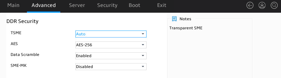
Table 34 Items on the DDR Security submenu screen
|
Item |
Description |
|
TSME |
Select whether to enable TSME. Options are: · Disabled. · Enabled. · Auto (default). |
|
AES |
Select an AES encryption algorithm. Options are: · AES-256 (default). · AES-128. |
|
Data Scramble |
Select whether to enable data scramble. Options are: · Enabled (default). · Disabled. |
|
SME-MK |
Select whether to enable SME-MK encryption. Options are: · Enabled. · Disabled (default). |
DDR PMIC Configuration submenu
Figure 51 shows the DDR PMIC Configuration submenu screen. The submenu items are described in Table 35.
Figure 51 DDR PMIC Configuration submenu screen
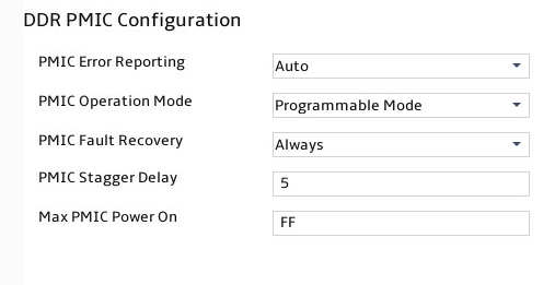
Table 35 Items on the DDR PMIC Configuration submenu screen
|
Item |
Description |
|
PMIC Error Reporting |
Select whether to enable Power Management IC (PMIC) error report. Options are: · False—Disable PMIC error report. · Ture—Enable PMIC error report. · Auto (default). |
|
PMIC Operation Mode |
Select the PMIC operation mode. Options are: · Secure Mode. · Programmable Mode (default). |
|
PMIC Fault Recovery |
Select whether to perform PMIC fault recovery. Options are: · Always (default). · Never. · Once. |
|
PMIC Stagger Delay |
Set the PMIC stagger delay. The default is 5 ms. |
|
Max PMIC Power On |
Set the maximum number of DDRs to power on. The default is FF. |
DDR Miscellaneous submenu
Figure 52 shows the DDR Miscellaneous submenu screen. The submenu items are described in Table 36.
Figure 52 DDR Miscellaneous submenu screen
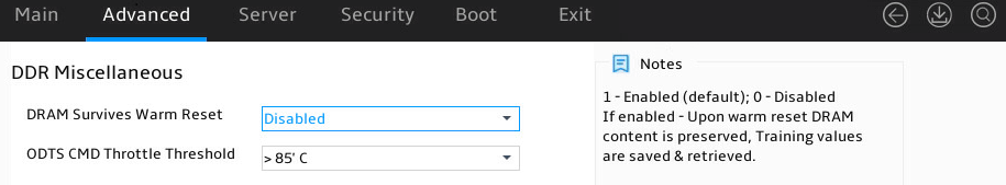
Table 36 Items on the DDR Miscellaneous submenu screen
|
Item |
Description |
|
DRAM Survives Warm Reset |
Select whether to enable DRAM to survive warm reset. Options are: · Disabled (default). · Enabled. |
|
ODTS CMD Throttle Threshold |
Set the ODTS CMD throttle threshold. Options are: · > 85°C (default). · > 90°C. · > 95°C. |
DDR PHY(CMN) submenu
Figure 53 shows the DDR PHY(CMN) submenu screen. The submenu items are described in Table 37.
Figure 53 DDR PHY(CMN) submenu screen

Table 37 Items on the DDR PHY(CMN) submenu screen
|
Item |
Description |
|
Periodic Training |
Select whether to enable periodic training. Options are: · Disabled. · Enabled. · Auto (default). |
|
Periodic Training Interval |
This item is available only when the Periodic Training item is Enabled. Set the periodic training interval. The value is in the range of 0 to 4095, in ms. The default is 1000. |
NBIO Common Options menu
Figure 54 shows the NBIO Common Options submenu screen, on which you can configure the NorthBridge IO (NBIO) settings, including RAS settings and AER settings. The submenu items are described in Table 38.
Figure 54 NBIO Common Options submenu screen
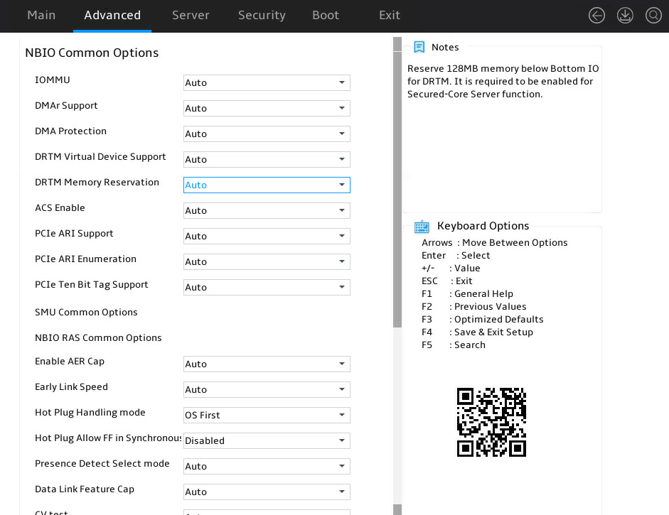
Table 38 Items on the NBIO Common Options submenu screen
|
Item |
Description |
|
IOMMU |
Select whether to enable Input-Output Memory Management Unit (IOMMU). Options are: · Auto (default). · Enabled. · Disabled. |
|
DMAr Support |
Select whether to enable Direct Memory Access (DMA) mapping. Options are: · Auto (default). · Enabled. · Disabled. |
|
DMA Protection |
Select whether to enable DMA protection. Options are: · Auto (default). · Enabled. · Disabled. |
|
DRTM Virtual Device Support |
Select whether to enable support for DRTM virtual devices. Options are: · Auto (default). · Enabled. · Disabled. |
|
DRTM Memory Reservation |
Select whether to enable DRTM memory reservation. Options are: · Auto (default). · Enabled. · Disabled. |
|
ACS Enable |
Select whether to enable Access Control Services (ACS). To enable ACS, you must first enable PCIe AER. Options are: · Auto (default). · Enabled. · Disabled. |
|
PCIe ARI Support |
Select whether to enable PCIe Alternative Routing-ID (ARI). Options are: · Auto (default). · Enabled. · Disabled. |
|
PCIe ARI Enumeration |
Select whether to enable PCIe ARI enumeration. Options are: · Auto (default). · Enabled. · Disabled. |
|
PCIe Ten Bit Tag Support |
Select whether to enable PCIe 10-bit tag. Options are: · Auto (default). · Enabled. · Disabled. |
|
SMU Common Options |
Submenu for configuring SMU common settings. |
|
NBIO RAS Common Options |
Submenu for configuring NBIO RAS common settings. |
|
Enable AER Cap |
Select whether to enable AER Cap. Options are: · Auto (default). · Enabled. · Disabled. |
|
Early Link Speed |
Set the early link speed. Options are: · Auto (default). · Gen1. · Gen2. |
|
Hot Plug Handling mode |
Select the hot-plug handling mode. Options are: · OS First (default). · Firmware First/EDR if OS supports. · Firmware First but allow OS First. · System Firmware Intermediary. · Auto. |
|
Hot Plug Allow FF in Synchronous |
Select whether to enable hot-pluggable synchronous FF. Options are: · Enabled. · Disabled (default). |
|
Presence Detect Select mode |
Select the presence detection mode. Options are: · OR—In-band or out-of-band. · AND—In-band and out-of-band. · In-Band Only. · Out-Of-Band Only. · Auto (default). |
|
Data Link Feature Cap |
Select whether to enable data link feature cap. Options are: · Auto (default). · Enabled. · Disabled. |
|
Data Link Feature Exchange |
This item is available only when the Data Link Feature Cap item is set to Enabled. Select whether to enable data link feature exchange. Options are: · Auto (default). · Enabled. · Disabled. |
|
CV test |
Select whether to enable CV test. Options are: · Auto (default). · Enabled. · Disabled. |
|
SEV-SNP Support |
Select whether to enable SEV-SNP. Options are: · Auto (default). · Enabled. · Disabled. |
|
Allow Compliance |
Select whether to enable standards compliance. Options are: · Auto (default). · Enabled. · Disabled. |
|
SRIS |
Select whether to enable SRIS. Options are: · Auto (default). · Enabled. · Disabled. |
|
Multi Upstream Auto Speed Change |
Select whether to enable multi-upstream auto speed change. Options are: · Auto (default). · Enabled. · Disabled. |
|
Multi Auto Speed Change On Last Rate |
Select whether to enable auto speed change based on the last rate. Options are: · Auto (default). · Enabled. · Disabled. |
|
PCIE Link Speed Capability |
Set the PCIe link speed. Options are: · Auto (default). · Maximum speed. · Gen 1 to Gen 5. |
|
RTM Margining Support |
Select whether to enable RTM margining. Options are: · Auto (default). · Enabled. · Disabled. |
|
EQ Bypass To Highest Rate |
Select whether to enable EQ bypass to the highest rate. Options are: · Auto (default). · Enabled. · Disabled. |
|
Non-PCIe Compliant Support |
Select whether to enable non-PCIe compliance. Options are: · Auto (default). · Enabled. · Disabled. |
|
PCIE Idle Power Setting |
Select the PCIE idle power policy. Options are: · Optimize for Latency (default). · Optimize for Perf/Power. |
|
nBif Common Options |
Submenu for configuring nBif common settings. |
|
Enable 2 SPC (Gen 4) |
Select whether to enable 2 SPC (Gen 4). At the Gen4 speed, enabling this option allows use of two symbols per clock cycle. Options are: · Auto (default). · Enabled. |
SMU Common Options submenu
Figure 55 shows the SMU Common Options submenu screen. The submenu items are described in Table 39.
Figure 55 SMU Common Options submenu screen
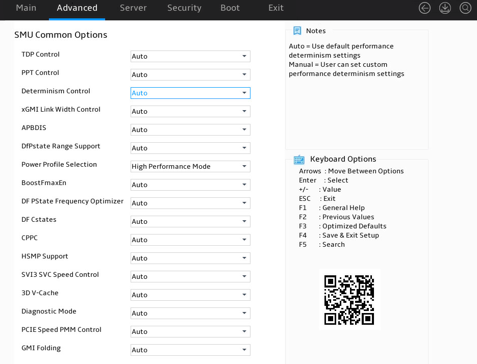
Table 39 Items on the SMU Common Options submenu screen
|
Item |
Description |
|
TDP Control |
Select the TDP configuration method. Options are: · Auto. · Manual (default). |
|
TDP |
This item is available only when the TDP Control item is set to Manual. The value is a decimal number. The default is 0. |
|
PPT Control |
Select the PPT configuration method. Options are: · Auto (default). · Manual. |
|
PPT |
This item is available only when the PPT Control item is set to Manual. The value is a decimal number. The default is 0. |
|
Determinism Control |
Select the power consumption policy configuration method. Options are: · Auto (default). · Manual. |
|
Determinism Enable |
This item is available only when the Determinism Control item is set to Manual. Select the power consumption policy. Options are: · Power (default)—Energy saving first. · Performance—Performance first. |
|
xGMI Link Width Control |
Select the xGMI link width configuration method. Options are: · Auto (default). · Manual. |
|
xGMI Force Link Width |
This item is available only when the xGMI Force Link Width Control item is set to Force. Set the xGMI forced link width. Options are: · 0. · 1. · 2. · Auto (default). |
|
xGMI Force Link Width Control |
This item is available only when the xGMI Link Width Control item is set to Manual. Select whether to force-configure the xGMI link width. Options are: · Unforce. · Force. · Auto (default). |
|
xGMI Max Link Width |
This item is available only when the xGMI Max Link Width Control item is set to Manual. Set the xGMI max link width. Options are: · Auto (default). · 1/2/3. |
|
xGMI Max Link Width Control |
This item is available only when the xGMI Link Width Control item is set to Manual. Select the xGMI max link width configuration method. Options are: · Auto (default). · Manual. |
|
APBDIS |
Set the Algorithm Performance Boost Disable (APBDIS) mode. Options are: · Auto (default)—Set the mode to 0 automatically. · 0—Non-mission mode. · 1—Mission mode. |
|
DFPstates |
This item is available only when the APBDIS item is set to 1. The value is in the range of 0 to 2. The default is 0. |
|
DfPstate Range Support |
Select whether to enable support for DF P state range. After you enable this feature, you can configure the DF P state range. Options are: · Auto (default). · Enabled. · Disabled. |
|
MaxDfPstate |
Set the maximum DF P state value. The value is in the range of 0 to 2. The default is 0. |
|
MinDfPstate |
Set the minimum DF P state value. The value is in the range of 0 to 2. The default is 0. |
|
Power Profile Selection |
Select a power profile. Options are: · High Performance Mode (default). · Efficiency Mode. · Maximum IO Performance Mode. |
|
BoostFmaxEn |
Select the Fmax configuration method. Options are: · Auto (default). · Manual. |
|
BoostFmax |
This item is available only when the BoostFmaxEn item is set to Manual. Set the BoostFmax. The value is a decimal number. The default is 0. |
|
DF PState Frequency Optimizer |
Select whether to enable DF P state frequency optimization. Options are: · Auto (default). · Enabled—Enable DF P-state CCLK effective frequency optimization. · Disabled—Disable DF P-state CCLK effective frequency optimization. |
|
DF Cstates |
Select whether to enable DF C state. Options are: · Auto. · Enabled · Disabled (default). |
|
CPPC |
Select whether to enable Collaborative Processor Performance Control (CPPC). Options are: · Auto (default). · Enabled. · Disabled. |
|
HSMP Support |
Select whether to enable HSMP. Options are: · Auto (default). · Enabled. · Disabled. |
|
SVI3 SVC Speed Control |
Select the SVI3 SVC speed configuration method. Options are: · Auto (default). · Manual. |
|
SVI3 SVC Speed |
Set the SVI3 SVC speed. Options are: · 20.00 MHz (default). · 13.33 MHz. · 5.00 MHz. |
|
3D V-Cache |
Configure the 3D V-Cache settings. AMD 3D V-Cache is a packaging technology that can be used to stack an additional cache layer to a CPU. Options are: · Auto (default). · 1 stack—Stack one additional cache layer. · Disabled—Disable 3D V-Cache. |
|
Diagnostic Mode |
Select whether to enable the diagnostic mode. Options are: · Auto (default). · Enabled. · Disabled. |
|
PCIE Speed PMM Control |
Select the PCIe speed control method to reduce the bandwidth speed when the device is idle. Options are: · Auto (default). · Dynamic link speed determined by Power Management functionality. · Static Target Link Speed (GEN4). · Static Target Link Speed (GEN5). |
NBIO RAS Common Options submenu
Figure 56 shows the NBIO RAS Common Options submenu screen. The submenu items are described in Table 40.
Figure 56 Items on the NBIO RAS Common Options submenu screen
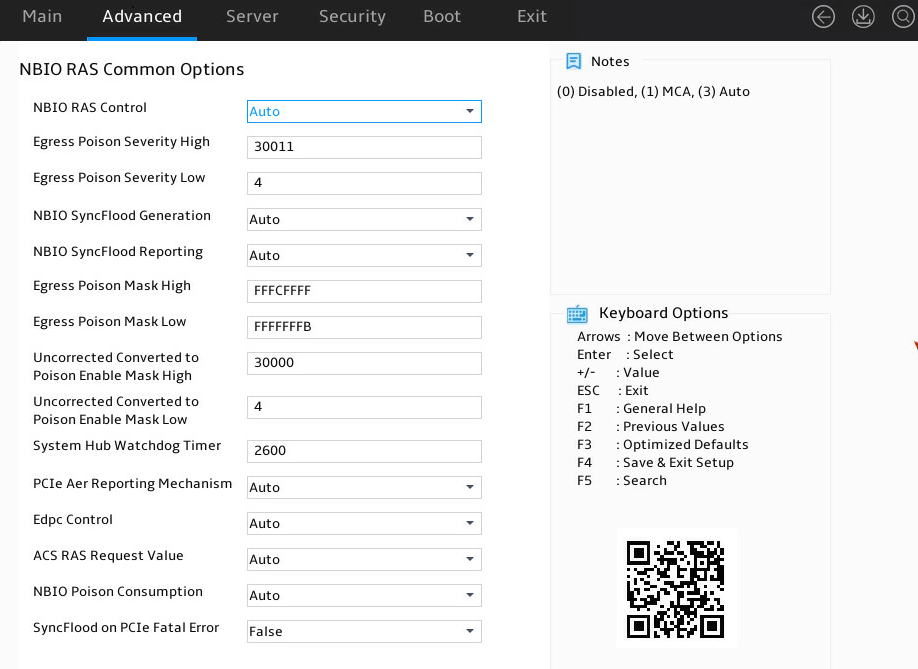
Table 40 Items on the NBIO RAS Common Options submenu screen
|
Item |
Description |
|
NBIO RAS Control |
Select whether to disable NBIO RAS or enable MCA. Options are: · Disabled—Disable NBIO RAS. · MCA—Enable MCA. · Auto (default). |
|
Egress Poison Severity High |
Set the highest error data egress severity. The default is 30011. |
|
Egress Poison Severity Low |
Set the lowest error data egress severity. The default is 4. |
|
NBIO SyncFlood Generation |
Select whether to enable Non-Blocking Input Output (NBIO) SyncFlood generation. Options are: · Disabled. · Enabled. · Auto (default). |
|
NBIO SyncFlood Reporting |
Select whether to enable NBIO SyncFlood report. Options are: · Disabled. · Enabled. · Auto (default). |
|
Egress Poison Mask High |
Set the highest error data mask. The default is FFFCFFFF. |
|
Egress Poison Mask Low |
Set the lowest error data mask. The default is FFFFFFFB. |
|
Uncorrected Converted to Poison Enable Mask High |
Set the highest data that can be converted to an error data mask. The default is 30000. |
|
Uncorrected Converted to Poison Enable Mask Low |
Set the lowest data that can be converted to an error data mask. The default is 4. |
|
System Hub Watchdog Timer |
Set the system hub watchdog timer. The default is 2600. |
|
PCIe Aer Reporting Mechanism |
Select the PCIe AER report mechanism. Options are: · Firmware First. · OS First. · Firmware First but allow OS First. · Auto (default). |
|
Edpc Control |
Select whether to enable Enhanced Downstream Port Containment (eDPC) on external-facing PCIe root ports that connect to external PCIe devices. Options are: · Disabled. · Enabled. · Auto (default). |
|
ACS RAS Request Value |
Set the Auto-Configuration Server (ACS) RAS request value. Options are: · Direct Request Access Enabled. · Request Blocking Enabled. · Request Redirect Enabled. · Auto (default). |
|
NBIO Poison Consumption |
Select whether to enable NBIO poison consumption. Options are: · Disabled—Disable NBIO poison consumption. · Enabled—Enable NBIO poison consumption. After NBIO poison consumption is enabled, NBIO will consume data that has already been marked as infected and generate an MCE exception. · Auto (default). |
|
Sync Flood on PCIe Fatal Error |
Select whether to enable SyncFlood upon a PCIe fatal error. Options are: · True—Enable SyncFlood upon a PCIe fatal error. · False (default)—Disable SyncFlood upon a PCIe fatal error. · Auto. |
nBif Common Options submenu
Figure 57 shows the nBif Common Options submenu screen. The submenu items are described in Table 41.
Figure 57 nBif Common Options submenu screen
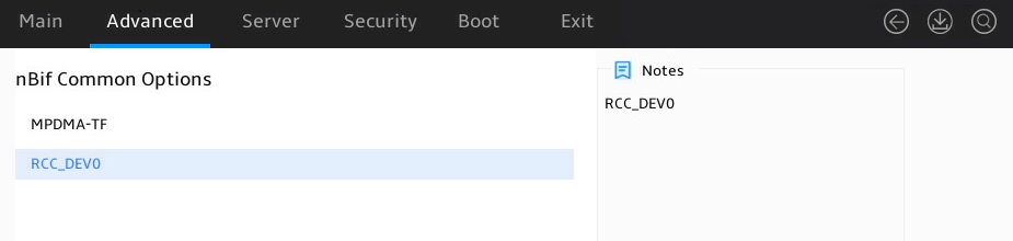
Table 41 Items on the nBif Common Options submenu screen
|
Item |
Description |
|
MPDMA-TF |
Submenu for configuring MPDMA-TF. |
|
RCC_DEV0 |
Submenu for configuring RCC_DEV0. |
FCH Common Options submenu
As shown in Figure 58, the FCH Common Options submenu contains the items described in Table 42.
Figure 58 FCH Common Options submenu screen
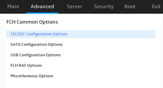
Table 42 Items on the FCH Common Options submenu screen
|
Item |
Description |
|
I3C/I2C Configuration Options |
Submenu for configuring I3C/I2C. |
|
SATA Configuration Options |
Submenu for configuring SATA. |
|
USB Configuration Options |
Submenu for configuring USB. |
|
FCH RAS Options |
Submenu for configuring FCH RAS. |
|
Miscellaneous Options |
Submenu for configuring miscellaneous settings. |
I3C/I2C Configuration Options submenu
Figure 59 shows the I3C/I2C Configuration Options submenu screen. The submenu items are described in Table 43.
Figure 59 I3C/I2C Configuration Options submenu screen
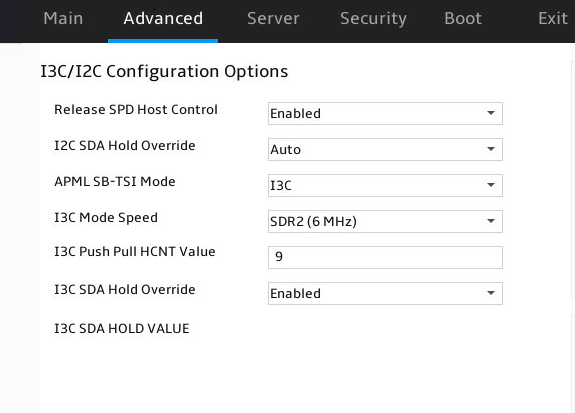
Table 43 Items on the I3C/I2C Configuration Options submenu screen
|
Item |
Description |
Default |
|
Release SPD Host Control |
Select whether to release SPD host control. With this feature enabled, BMC can take over I3C/I2C bus control. Options: · Disabled. · Enabled. · Auto. |
Enabled |
|
PMFW Poll DDR5 Telemetry |
Select whether to enable PMFW DDR5 telemetry. Options: · Disabled. · Enabled. · Auto. This item is available only when Release SPD Host Control is set to Disabled. |
Auto |
|
I2C SDA Hold Override |
This item overrides the IC_SDA_HOLD register for I2C. Options: · Disabled. · Enabled. · Auto. |
Auto |
|
I2C SDA TX HOLD VALUE |
Set the hold time for I2C SDA data transmission. |
35 |
|
I2C SDA RX HOLD VALUE |
Set the hold time for I2C SDA data reception. |
0 |
|
APML SB-TSI Mode |
Select the APML SB-TSI mode. Options: · I3C. · I2C. |
I3C |
|
I3C Mode Speed |
Set the I3C mode speed. Options: · SDR2(6 MHz). · Auto. |
N/A |
|
I3C Push Pull HCNT Value |
Set the HCNT value for I3C push-pull data transfer. |
9 |
|
I3C SDA Hold Override |
Select whether to enable I3C SDA hold override. This feature overrides the IC_SDA_HOLD register for I3C. Options: · Disabled. · Enabled. · Auto. |
Enabled |
|
I3C SDA HOLD VALUE |
Set the value for I3C SDA. |
5 |
SATA Configuration Options submenu
Figure 60 shows the SATA Configuration Options submenu screen. The submenu items are described in Table 44.
Figure 60 SATA Configuration Options submenu screen
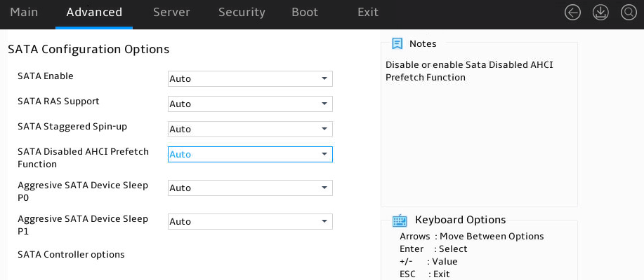
Table 44 Items on the SATA Configuration Options submenu screen
|
Item |
Description |
Default |
|
SATA Enable |
Select whether to enable the SATA controller. Options: · Auto. · Enabled. · Disabled. |
Auto |
|
SATA Mode |
Select the SATA mode. Options: · Auto. · AHCI. · AHCI as ID 0x7904. This item is available only when SATA Enable is set to Enabled. |
AHCI |
|
SATA RAS Support |
Select whether to enable SATA RAS support. Options: · Auto. · Enabled. · Disabled. |
Auto |
|
SATA Staggered Spin-up |
Select whether to enable SATA staggered spin-up. Options: · Auto. · Enabled. · Disabled. |
Auto |
|
SATA Disabled AHCI Prefetch Function |
Select whether to disable AHCI prefetch. Options: · Auto. · Enabled—To disable AHCI prefetch. · Disabled—Not to disable AHCI prefetch. |
Auto |
|
Aggresive SATA Device Sleep P0 |
Select whether to enable aggressive sleep mode for SATA devices connected to port P0. Options: · Auto. · Enabled. · Disabled. |
Auto |
|
DevSleep0 Port Number |
Set the number of DevSleep0 ports. |
0 |
|
Aggresive SATA Device Sleep P1 |
Select whether to enable aggressive sleep mode for SATA devices connected to port P1. Options: · Auto. · Enabled. · Disabled. |
Auto |
|
DevSleep1 Port Number |
Set the number of DevSleep ports. |
0 |
|
SATA Controller options |
SATA controller configuration menu. You can configure the following port parameters: · SATA Controller Enable. · SATA Controller eSATA. · SATA Controller DevSlp. · SATA Controller SGPIO. |
N/A |
USB Configuration Options submenu
Figure 61 shows the USB Configuration Options submenu screen. The submenu items are described in Table 45.
Figure 61 USB Configuration Options submenu screen
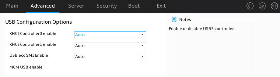
Table 45 Items on the USB Common Options submenu screen
|
Item |
Description |
Default |
|
XHCI Controller0 enable |
Select whether to enable XHCI Controller0. Options: · Auto. · Enabled. · Disabled. |
Auto |
|
XHCI Controller1 enable |
Select whether to enable XHCI Controller1. Options: · Auto. · Enabled. · Disabled. |
Auto |
|
USB ecc SMI Enable |
Select whether to enable USB ecc SMI. Options: · Auto. · Enabled. · Off. |
Auto |
|
MCM USB enable |
Submenu for configuring Multi-Chip Module (MCM) USB settings. |
N/A |
Figure 62 shows the MCM USB enable submenu screen. The submenu items are described in Table 46.
Figure 62 MCM USB enable submenu screen
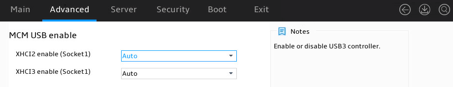
Table 46 Items on the MCM USB enable submenu screen
|
Item |
Description |
Default |
|
XHCI2 enable (Socket1) |
Select whether to enable XHCI2 for Socket1. Options: · Auto. · Enabled. · Disabled. |
Auto |
|
XHCI3 enable (Socket1) |
Select whether to enable XHCI3 for Socket1. Options: · Auto. · Enabled. · Disabled. |
Auto |
FCH RAS Options submenu
Figure 63 shows the FCH RAS Options submenu screen. The submenu items are described in Table 47.
Figure 63 FCH RAS Options submenu screen
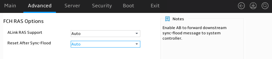
Table 47 Items on the FCH RAS Options submenu screen
|
Item |
Description |
Default |
|
ALink RAS Support |
Select whether to enable A-Link RAS support. With this feature enabled, the system can perform FCH A-Link parity error check. Options: · Auto. · Enabled. · Disabled. |
Auto |
|
Reset After Sync-Flood |
Select whether to enable reset after Sync flood. Options: · Auto. · Enabled. · Disabled. |
Auto |
Miscellaneous Options submenu
Figure 64 shows the Miscellaneous Options submenu screen. The submenu items are described in Table 48.
Figure 64 Miscellaneous Options submenu screen

Table 48 Items on the Miscellaneous Options submenu screen
|
Item |
Description |
Default |
|
Boot Timer Enable |
Select whether to enable the boot timer. Options: · Auto. · Enabled. · Disabled. |
Auto |
Soc Miscellaneous Control submenu
As shown in Figure 65, the Soc Miscellaneous Control submenu contains the items described in Table 49.
Figure 65 Soc Miscellaneous Control submenu screen
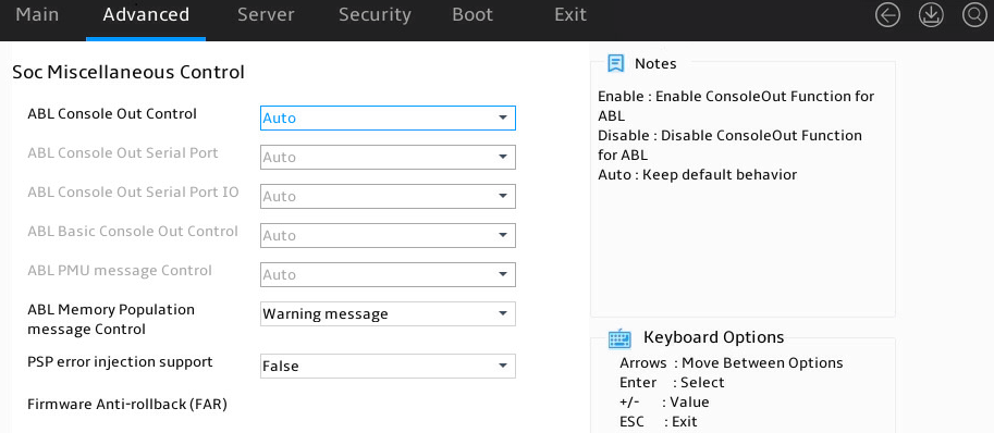
Table 49 Items on the Soc Miscellaneous Control submenu screen
|
Item |
Description |
Default |
|
ABL Console Out Control |
Select whether to enable ABL Console Out Control. Options: · Disabled. · Enabled. · Auto. |
Auto |
|
ABL Console Out Serial Port |
Select whether to enable ABL Console Out Serial Port. Options: · eSPI UART. · SOC UART0. · SOC UART1. · Auto. This item is available only when ABL Console Out Control is set to Enabled. |
Auto |
|
ABL Console Out Serial Port IO |
Select whether to enable ABL Console Out Serial Port IO. Options: · 0x3F8. · 0x2F8. · 0x3E8. · 0x2E8. · Auto. This item is available only when ABL Console Out Serial Port is set to eSPI UART. |
Auto |
|
ABL Basic Console Out Control |
Select whether to enable ABL Basic Console Out Control. Options: · Disabled. · Enabled. · Auto. This item is available only when ABL Console Out Control is set to Enabled. |
Auto |
|
ABL PMU message Control |
Select whether to enable ABL PMU message Control. Options: · Detailed debug message. · Coarse debug message. · Stage completion. · Assertion messages. · Firmware completion message only. · Auto. This item is available only when ABL Console Out Control is set to Enabled. |
Auto |
|
ABL Memory Population message Control |
Set the ABL memory population message option. Options: · Warning message. · Fatal error. |
N/A |
|
PSP error injection support |
Select whether to enable support for injecting errors into PSP. Options: · False. · True. |
False |
Workload Tuning submenu
As shown in Figure 66, the Workload Tuning submenu contains the items described in Table 50.
Figure 66 Workload Tuning submenu screen
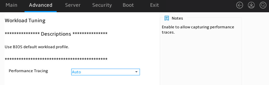
Table 50 Items on the Workload Tuning submenu screen
|
Item |
Description |
Default |
|
Performance Tracing |
Select whether to enable performance tracing. If you enable this feature, collection of performance records is allowed. Options: · Auto. · Enabled. · Disabled. |
Auto |
AMD PBS submenu
As shown in Figure 67, the AMD PBS submenu mainly contains AMD PBS-related configuration items, which are described in Table 51.
Figure 67 AMD PBS submenu screen
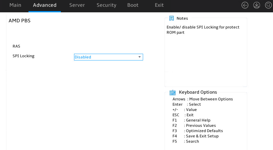
Table 51 Items on the AMD PBS submenu screen
|
Item |
Description |
Default |
|
RAS |
Submenu for configuring RAS. |
N/A |
|
SPI Locking |
Select whether to enable SPI locking to protect the ROM area. Options: · Disabled. · Enabled. |
Disabled |
RAS submenu
As shown in Figure 68, the PBS submenu mainly contains PBS-related configuration items, which are described in Table 52.
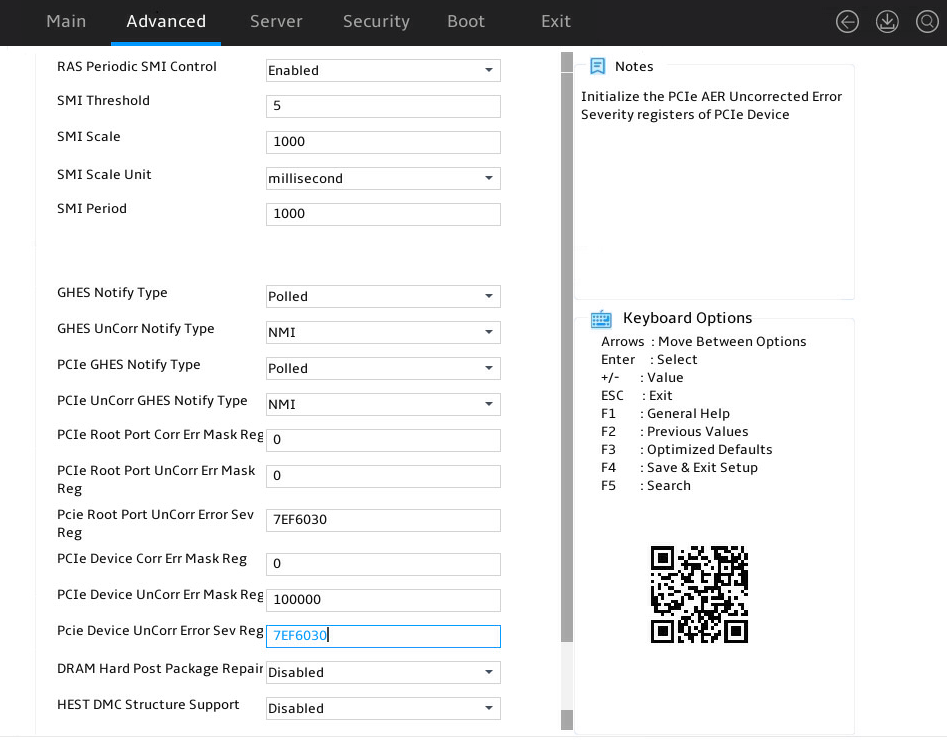
Table 52 Items on the RAS submenu screen
|
Item |
Description |
Default |
|
RAS Periodic SMI Control |
Select whether to enable RAS periodic System Management Interrupt (SMI) control. With this feature enabled, SMI can report polling errors. Options: · Enabled. · Disabled. |
Enabled |
|
SMI Threshold |
Set the SMI threshold. |
5 |
|
SMI Scale |
Set a time scale for SMI. |
1000 |
|
SMI Scale Unit |
Set a SMI scale unit. Options: · millisecond. · second. · minute. |
N/A |
|
SMI Period |
Set a polling period for SMI, in milliseconds. The maximum value is 32767. To disable SMI, set the value to 0. |
1000 |
|
GHES Notify Type |
Set the notification type for Generic Hardware Error Sources (GHESs). Options: · Polled. · SCI. |
Polled |
|
GHES UnCorr Notify Type |
Set the notification type for uncorrected GHESs. Options: · Polled. · NMI. |
NMI |
|
PCIe GHES Notify Type |
Set the notification type for PCIe GHESs. Options: · Polled. · SCI. |
Polled |
|
PCIe UnCorr GHES Notify Type |
Set the notification type for uncorrected PCIe GHESs. Options: · Polled. · NMI. |
NMI |
|
PCIe Root Port Corr Err Mask Reg |
Set a value for the corrected error mask register of the PCIe root port. |
0 |
|
PCIe Root Port UnCorr Err Mask Reg |
Set a value for the uncorrected error mask register of the PCIe root port. |
0 |
|
PCIe Root Port UnCorr Error Sev Reg |
Set a value for the uncorrected error severity register of the PCIe root port. |
7EF6030 |
|
PCIe Device Corr Err Mask Reg |
Set a value for the corrected error mask register of the PCIe device. |
0 |
|
PCIe Device UnCorr Err Mask Reg |
Set a value for uncorrected error mask register of the PCIe device. |
100000 |
|
Pcie Device UnCorr Error Sev Reg |
Set a value for uncorrected error severity register of the PCIe device. |
7EF6030 |
|
DRAM Hard Post Package Repair |
Select whether to enable DRAM hardware startup repair. Options: · Enabled. · Disabled. |
Disabled |
|
HEST DMC Structure Support |
Select whether to enable DMC structure support for hardware error source tables. Options: · Enabled. · Disabled. |
Disabled |
Trusted Computing submenu
The Trusted Computing submenu displays the information for trusted computing modules (including TPMs and TCMs) accessed by the server. You can configure related settings on this page. The displayed submenu screen might vary by the installed security module.
· A TPM is a microchip built into the system board. It has an independent processor and storage unit for storing encrypted information (such as keys), providing encryption and installation certification services for the server. A TPM is typically used in conjunction with drive encryption technology, such as Microsoft Windows BitLocker drive encryption technology. BitLocker uses TPM to help protect the Windows operating system and user data, ensuring that data tampering does not occur even when the data is unattended, lost, or stolen. For more information about BitLocker, visit the Microsoft website http://www.microsoft.com.
· A TCM is a hardware module that provides cryptographic operation functions for a trusted computing platform and has a protected storage space.
|
|
NOTE: If you press F3 to restore defaults, the TCM and TPM settings will not be restored to defaults. |
As shown in Figure 69 and Figure 70, you can configure TCM and TPM settings on the Trusted Computing submenu. The submenu items are described in Table 53.
Figure 69 Trusted Computing submenu screen (no security module installed)
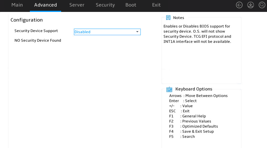
Figure 70 Trusted Computing submenu screen (TPM)
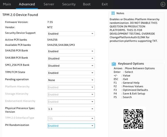
Table 53 Items on the Trusted Computing submenu screen
|
Item |
Description |
Default |
|
Security Device Support |
Select whether to enable support for the security device. Options: · Enabled. · Disabled. |
Enabled |
|
TPM/TCM State |
Select whether to enable the security device. To ensure successful change of the security device status, the system will restart after you change the setting for this item. Options: · Enabled. · Disabled. |
Enabled |
|
Pending Operation |
Set a pending operation. To ensure successful change of the security device status, the server will restart after you change the setting for this item. Options: · None—Disable this feature. · TCM Clear—Clears the TCM measurement values. |
None |
|
Current Status Information |
Current status information of the module. |
N/A |
|
TCM Enabled Status |
TCM is in enabled status. |
N/A |
|
TCM Active Status |
TCM is in active status. |
N/A |
|
TCM Owner Status |
Owner information of TCM. |
N/A |
PSP Firmware Versions submenu
As shown in Figure 71, the PSP Firmware Versions submenu displays basic PSP firmware version information. The submenut items are described in Table 54.
Figure 71 PSP Firmware Versions submenu screen
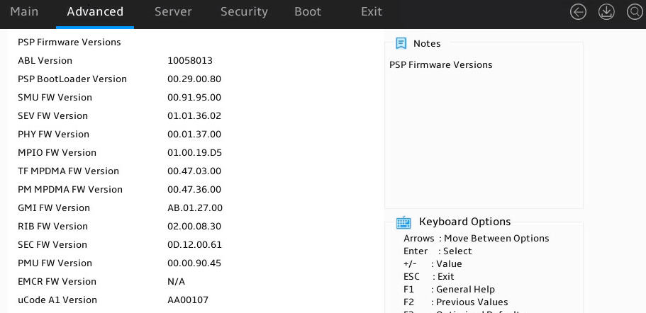
Table 54 Items on the PSP Firmware Versions submenu screen
|
Item |
Description |
|
PSP Firmware Version |
Version of the PSP firmware. |
|
ABL Version |
ABL version. |
|
PSP BootLoader Version |
Version of the PSP Bootloader. |
|
SMU FW Version |
Version of the SMU firmware. |
|
SEV FW Version |
Version of the SEV firmware. |
|
PHY FW Version |
Version of the PHY firmware. |
|
MPIO FW Version |
Version of the MPIO firmware. |
|
TF MMPDMA FW Version |
Version of the TF MMPDMA firmware. |
|
GMI FW Version |
Version of the GMI firmware. |
|
RIB FW Version |
Version of the RIB firmware. |
|
SEC FW Version |
Version of the SEC firmware. |
|
PMU FW Version |
Version of the PMU firmware. |
|
uCode B0 Version |
Version of the uCode B0 firmware. |
|
APCB Version |
APCB version. |
|
APOB Version |
APOB version. |
|
APPB Version |
APPB version. |
ACPI Settings submenu
Figure 72 shows the ACPI Settings submenu screen. The submenu items are described in Table 55.
Figure 72 ACPI Settings submenu screen
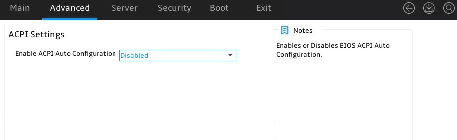
Table 55 Items on the ACPI Settings submenu screen
|
Item |
Description |
Default |
|
Enable ACPI Auto Configuration |
Select whether to enable ACPI auto configuration. Options: · Enabled. · Disabled. |
Disabled |
UEFI Variables Protection submenu
Figure 73 shows the UEFI Variables Protection submenu screen. The submenu items are described in Table 56.
Figure 73 UEFI Variables Protection submenu screen
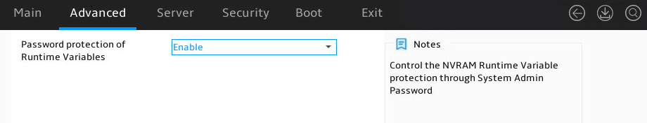
Table 56 Items on the UEFI Variables Protection submenu screen
|
Item |
Description |
Default |
|
Password protection of Runtime Variables |
Select whether to enable UEFI dynamic password protection. Options: · Enabled. · Disabled. |
Disabled |
Serial Port Console Redirections submenu
Figure 74 shows the Serial Port Console Redirections submenu screen. The submenu items are described in Table 57.
Figure 74 Serial Port Console Redirections submenu screen
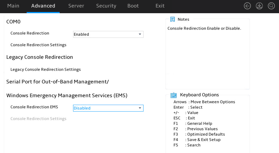
Table 57 Items on the Serial Port Console Redirections submenu screen
|
Item |
Description |
Default |
|
COM0 |
||
|
Console Redirection |
Select Enabled or Disabled to enable or disable console redirection on CMO0. If the feature is enabled, the data on a specific physical console or a virtual console will be redirected to the specified system console. |
Enabled |
|
Console Redirection Settings |
This item is available only when Console Redirection is set to Enabled on CMO0. Otherwise, it is grayed out. Configure console redirection settings. |
N/A |
|
Legacy Console Redirection |
||
|
Legacy Console Redirection Settings |
Configure console redirection settings. |
N/A |
|
Serial Port for Out-of-Band Management/Windows Emergency Management Services (EMS) |
||
|
Console Redirection EMS |
Select Enabled or Disabled to enable or disable console redirection for Windows emergency management services (EMS). |
Disabled |
|
Console Redirection Settings |
This item is available only when Console Redirection EMS is set to Enabled for Windows EMS. Otherwise, it is grayed out. Configure console redirection settings. |
N/A |
Console Redirection Settings submenu (COM0)
Figure 75 shows a Console Redirection Settings submenu screen for serial port COM0, on which you can configure the data exchange settings between the local and remote computers. The submenu items are described in Table 58.
Figure 75 Console Redirection Settings submenu screen (COM0)
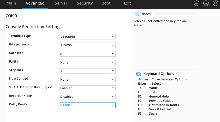
Table 58 Items on the Console Redirection Settings submenu screen (COM0)
|
Item |
Description |
Default |
|
Terminal Type |
Select the type of the terminal used for console redirection. Options: · VT100—Uses a supported VT100 video terminal with the ASCII character set. · VT100Plus—Uses a supported VT100-plus video terminal and its character set. VT100+ supports colors and function keys. · VT-UTF8—Uses a video terminal with the UTF-8 character set. · ANSI—Uses the ANSI character set, which is an extended ASCII character set. |
VT100Plus |
|
Bits Per Second |
Set the baud rate of the serial port in bits per second. Options: · 9600. · 19200. · 38400. · 57600. · 115200. This baud rate setting must match the setting on the remote terminal. As a best practice, set a low speed on a long or noisy serial line. |
115200 |
|
Data Bits |
Set the number of bits used to represent one character of data. Options: · 7. · 8. |
8 |
|
Parity |
Set the parity bit to be sent with the data bits for transmission error detection. Options: · None—Disables the transmission error detection feature. · Even—Sets the parity bit so that the number of ones in the data set is an even number. · Odd—Sets the parity bit so that the number of ones in the data set is an odd number. · Mark—Always sets the parity bit to 1. A parity bit value of 0 indicates that an error has occurred. · Space—Always sets the parity bit to 0. A non-zero parity bit indicates that an error has occurred. |
None |
|
Stop Bits |
Set the number of stop bits used to indicate the end of a serial data packet. Options: · 1. · 2. Two stop bits might be required for communications with a low-speed device. |
1 |
|
Flow Control |
Select a flow control method to prevent data loss from buffer overflow. Options: · None—No flow control is used. · Hardware RTS/CTS—Flow control that uses the ready to send/clear to send (RTS/CTS) signal. When you select this option, make sure it is supported on the serial port. If you enable hardware RTS/CTS on a serial port that does not support hardware flow control (such as a port that uses a USB-to-serial cable), or on a serial port with no cable connected, the following issues might occur: · Failure to load the option ROM of embedded and external PCIe modules. · Screen blackout. · Cursor flickering. |
None |
|
VT-UTF8 Combo Key Support |
Select Enabled or Disabled to enable or disable VT-UTF8 combination key support for ANSI/VT100 terminals. |
Enabled |
|
Putty KeyPad |
Select a mode to change the action of the function keys and keypad in PuTTY. Options: · VT100. · LINUX. · XTERMR6. · SCO. · ESCN. · VT400. |
VT100 |
Console Redirection Settings (Legacy) submenu
Figure 76 shows the Console Redirection Settings submenu screen, on which you can configure legacy console redirection settings. The submenu items are described in Table 59.
Figure 76 Console Redirection Settings (Legacy) submenu screen
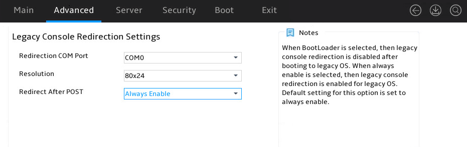
Table 59 Items on the Console Redirection Settings (Legacy) submenu screen
|
Item |
Description |
Default |
|
Redirection COM Port |
Select the redirection COM port. The only option is CMO0. |
CMO0 |
|
Resolution |
Set the resolution for legacy console redirection, in number of rows and columns. Options: · 80*24—Supports 80 rows and 24 columns. · 80*25—Supports 80 rows and 25 columns. |
80*24 |
|
Redirection After POST |
Select whether to enable or disable redirection after POST. Options: · Always Enable—Legacy console redirection is still enabled after the system boots into the OS. · BootLoader—Disables console redirection after the OS is booted. |
Always Enable |
Console Redirection Settings (EMS port) submenu
Figure 77 shows a Console Redirection Settings (EMS port) submenu screen. The submenu items are described in Table 60.
Figure 77 Console Redirection Settings (EMS port) submenu screen
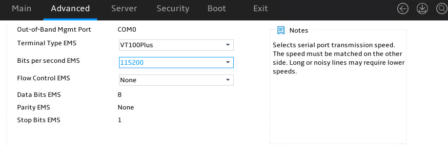
Table 60 Items on the Console Redirection Settings (EMS port) submenu screen
|
Item |
Description |
Default |
|
Out-of-Band Mgmt Port |
Indicate the EMS port. This port allows Microsoft Windows EMS to remotely access the Window OS to collect fault information. |
N/A |
|
Terminal Type EMS |
Select the type of the terminal used for console redirection. Options: · VT100—Uses a supported VT100 terminal with the ASCII character set. · VT100Plus—Uses a supported VT100plus terminal and its character set. VT100plus supports colors and function keys. · VT-UTF8—Uses a terminal with the UTF-8 character set. · ANSI—Uses the ANSI character set, which is an extended ASCII character set. |
VT100Plus |
|
Bits per second EMS |
Set the data transfer rate of the serial port in bits per second. Options: · 9600. · 19200. · 57600. · 115200. This data transfer rate setting must match the setting on the remote terminal. As a best practice, set a low speed on a long or noisy serial line. |
115200 |
|
Flow Control EMS |
Select a flow control method to prevent data loss from buffer overflow. Options: · None—No flow control is used. · Hardware RTS/CTS—Flow control that uses the ready to send/clear to send (RTS/CTS) signal. When you select this option, make sure it is supported on the serial port. · Software Xon/Xoff—Flow control that uses the XON (transmit ON) and XOFF (transmit OFF) control characters. When the data transfer rate exceeds 1200 bits per second, the receiver sends an XOFF to have the sender stop transmission. The sender will resume the transmission only when it receives an XON from the receiver. |
None |
|
Data Bits EMS |
Set the number of bits used to represent one character of data. |
N/A |
|
Parity EMS |
Set the parity bit to be sent with the data bits for transmission error detection. Options: · None—Disables the transmission error detection feature. · Even—Sets the parity bit so that the number of ones in the data set is an even number. · Odd—Sets the parity bit so that the number of ones in the data set is an odd number. · Mark—Always sets the parity bit to 1. A parity bit value of 0 indicates that an error has occurred. · Space—Always sets the parity bit to 0. A non-zero parity bit indicates that an error has occurred. The options displayed might vary according to the actual situation. |
None |
|
Stop Bits EMS |
Set the number of stop bits used to indicate the end of a serial data packet. |
N/A |
CPU Configuration submenu
Figure 78 shows the CPU Configuration submenu, on which you can view and configure CPU settings. The submenu items are described in Table 61.
Figure 78 CPU Configuration submenu screen
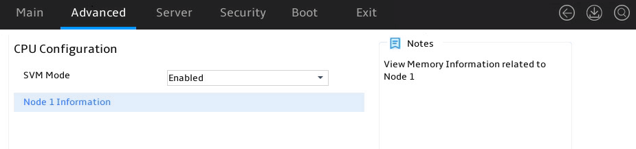
Table 61 Items on the CPU Configuration submenu screen
|
Item |
Description |
Default |
|
SVM Mode |
Select whether to enable the SVM mode. Options: · Enabled—Enables the SVM mode. If you enable the SVM mode, Virtual Machine Monitor (VMM) can use the additional hardware resources provided by CPUs. · Disabled—Disables the SVM mode. |
Enabled |
|
Node 1 Information |
Information for Node 1. |
N/A |
|
Node 2 Information |
Information for Node 2. |
N/A |
|
|
NOTE: The items on the Node 1 Information and Node 2 Information screens are the same. The following uses the Node 1 Information screen as an example. |
Node 1 Information subscreen
Figure 79 shows the Node 1 Information submenu screen. The submenu items are described in Table 62.
Figure 79 Node 1 Information submenu screen

Table 62 Items on the Node 1 Information submenu screen
|
Item |
Description |
|
AMD Eng Sample |
Displays the CPU manufacturer, CPU model, number of processor cores. |
|
32 Cores 64 Threads |
Displays the number of cores and threads. |
|
Running @ 2581 MHz 900 mV |
Displays available PCR banks. |
|
Processor Family |
Displays the processor family. |
|
Processor Model |
Displays the processor working mode. |
|
Microcode Patch Level |
Displays the microcode patch level. |
|
L1 Instruction Cache |
Displays the size and associativity of the L1 instruction cache. |
|
L1 Data Cache |
Displays the size and associativity of the L1 data cache. |
|
L2 Cache |
Displays the size and associativity of the L2 cache. |
|
L3 Cache per Socket |
Displays the size of the L3 cache for each processor. |
North Bridge submenu
Figure 80 shows the North Bridge submenu, on which you can view the total memory, memory presence, and other information. The submenu items are described in Table 63.
Figure 80 North Bridge submenu screen
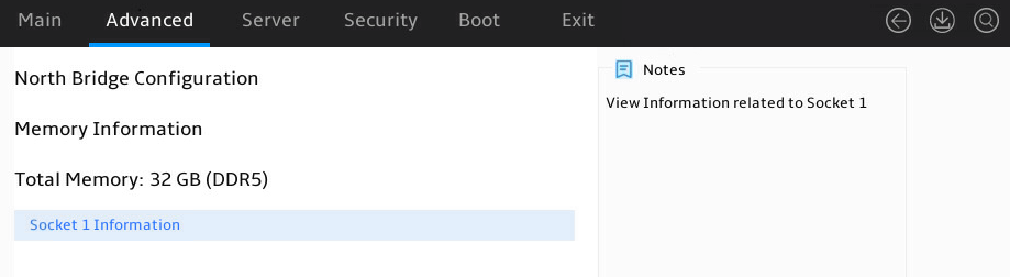
Table 63 Items on the North Bridge submenu screen
|
Item |
Description |
|
Memory Information |
Displays the memory information. |
|
Total Memory |
Displays the total memory, in GB. |
|
Socket 1 Information |
Memory information submenu for CPU Socket 1. |
|
Socket 2 Information |
Memory information submenu for CPU Socket 2. |
|
|
NOTE: Both Socket 1 Information and Socket 2 Information submenus display the memory presence and other information. The following uses the Socket 1 Information submenu as an example. |
Socket 1 Information submenu
As shown in Figure 81, the Socket 1 Information submenu contains items described in Table 64.
Figure 81 Socket 1 Information submenu screen
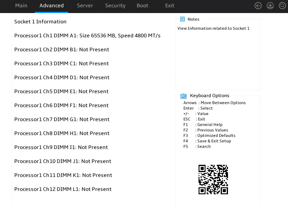
Table 64 Items on the Socket 1 Information submenu screen
|
Item |
Description |
|
Socket 1 Information |
Memory information of CPU Socket 1. |
|
Processor1 Ch1 DIMM A0:Size 32768 MB,Speed 2666 MT/s |
Memory information for slot Processor1 Ch1 DIMM A0: a memory capacity of 32768 MB and a memory speed of 2666 MT/s. |
PCI Subsystem Settings submenu
Figure 82 shows the PCI Subsystem Settings submenu screen, on which you can configure PCI subsystem settings as described Table 65.
Figure 82 PCI Subsystem Settings submenu screen
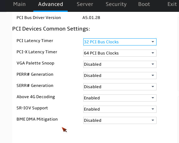
Table 65 Items on the PCI Subsystem Settings submenu screen
|
Item |
Description |
Default |
|
PCI Bus Driver Version |
Displays the PCI bus driver version. |
N/A |
|
PCI Devices Common Settings |
||
|
Above 4G Decoding |
Select Enabled or Disabled to enable or disable decoding of 64-bit PCIe modules in a 4 GB or greater address space. As a best practice, enable this option if the PCIe module has a 4 GB or higher-capacity VRAM. For example, disabling this option can cause an M60 or K80 GPU to get stuck in the EarlyPOST 100% phase, preventing you from accessing the BIOS setup menu or the OS. |
Enabled |
|
SR-IOV Support |
Select Enabled or Disabled to enable or disable support for PCIe single-root I/O virtualization (SR-IOV). SR-IOV virtualizes one physical PCIe module into multiple virtual PCIe modules, each of which can be bound to a virtual machine, thus allowing multiple accesses to the physical PCIe module. With SR-IOV support enabled, the BIOS allocates I/O resources if a PCIe module supports SR-IOV. With SR-IOV support disabled, the OS allocates I/O resources if a PCIe module supports SR-IOV. |
Enabled |
|
BME DMA Mitigation |
Select whether to enable Bus Master Enable (BME) DMA mitigation. This feature can prevent DMA side-channel attacks. Options: · Enabled—Enables the DMA access operation for PCIe channels. With this feature enabled, DMA side-channel attacks cannot be prevented but the performance of PCIe devices is normal. · Disabled—Disables the DMA access operation for PCIe channels, which will block DMA access and cause performance degradation of PCIe devices. |
Disabled |
USB Configuration submenu
Figure 83 shows the USB Configuration submenu screen, on which you can view connected USB devices and configure USB settings as described in Table 66.
Figure 83 USB Configuration submenu screen
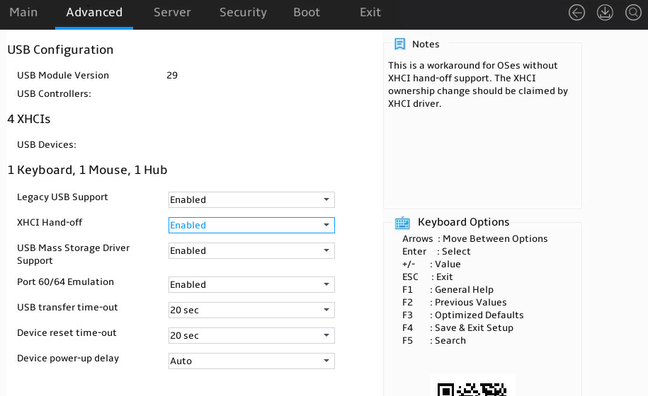
Table 66 Items on the USB Configuration submenu screen
|
Item |
Description |
Default |
|
USB Module Version |
Displays the USB module version. |
N/A |
|
USB Controllers |
Displays the detected USB controllers. The system supports eXtensible Host Controller (XHCI) controllers that support USB 3.0. |
N/A |
|
USB Devices |
Displays the numbers of connected USB devices, including drives, keyboards, mouses, and hubs. |
N/A |
|
Legacy USB Support |
Select whether to enable support for legacy USB devices. Options: · Enabled—Legacy USB support is always enabled. · Disabled—USB devices are available only for UEFI applications. · Auto—The system automatically disables legacy USB support if no USB devices are connected. |
Enabled |
|
XHCI Hand-off |
Select Enabled or Disabled to enable or disable the eXtensible Host Controller Interface (xHCI) hand-off feature. This feature is applicable to USB 3.0 and is used to manage the control rights for USB 3.0 XHCI. |
Enabled |
|
USB Mass Storage Driver Support |
Select Enabled or Disabled to enable or disable the support for USB mass storage drivers. |
Enabled |
CSM Configuration submenu
The configuration support module (CSM) provides UEFI compatibility with OSs that do not support UEFI boot mode.
Figure 84 shows the CSM Configuration submenu screen, on which you can configure CMS settings as described in Table 67.
Figure 84 CSM Configuration submenu screen
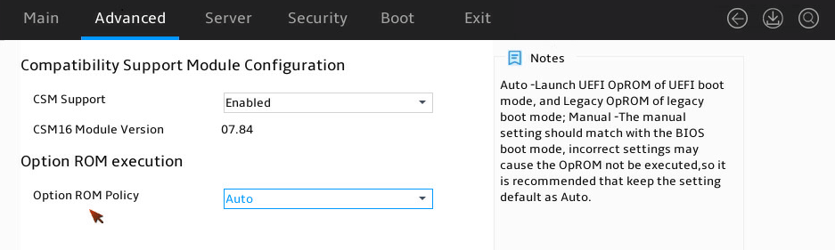
Table 67 Items on the CSM Configuration submenu screen
|
Item |
Description |
Default |
|
CSM Support |
Select Enabled or Disabled to enable or disable support for UEFI-incapable operating systems. You must enable CSM support in legacy boot mode. |
Enabled |
|
CSM16 Module Version |
Displays the version of the CSM 16 module. |
N/A |
|
GateA20 Active |
Gate20 activation settings. Options: · Upon Request. · Always. |
N/A |
|
INT19 Trap Response |
INT19 trap response settings. Options: · Immediate. · Postponed. |
N/A |
|
Option ROM execution |
Displays ROM execution settings. |
N/A |
|
Option ROM Policy |
Select the option ROM load method for each type of devices. Options: · Auto—The system automatically loads the option ROMs. · Manual—Manually configure the load method for option ROMs. Incorrect settings might result in load failures. |
Auto |
|
Network |
Select the option ROM load method for network adapters. This option is available when Option ROM Policy is set to Manual. Options: · Do not launch—Do not load. · UEFI—Loads the option ROM for network adapters in UEFI boot mode. · Legacy—Loads the option ROM for network adapters in legacy boot mode. |
· In UEFI boot mode: UEFI. · In legacy boot mode: Legacy. |
|
Storage |
Select the option ROM load method for storage devices. This option is available when Option ROM Policy is set to Manual. Options: · Do not launch—Do not load. · UEFI—Loads the option ROM for storage devices in UEFI boot mode. · Legacy—Loads the option ROM for storage devices in legacy boot mode. |
· In UEFI boot mode: UEFI. · In legacy boot mode: Legacy. |
|
Video |
Select the option ROM load method for video devices. This option is available when Option ROM Policy is set to Manual. Options: · Do not launch—Do not load. · UEFI—Loads the option ROM for video cards in UEFI boot mode. · Legacy—Loads the option ROM for video cards in legacy boot mode. |
· In UEFI boot mode: UEFI. · In legacy boot mode: Legacy. |
|
Other PCI devices |
Select the option ROM load method for other PCI devices such as input devices. This option is available when Option ROM Policy is set to Manual. Options: · Do not launch—Do not load. · UEFI—Loads the option ROM for other PCI devices in UEFI boot mode. · Legacy—Loads the option ROM for other PCI devices in legacy boot mode. |
· In UEFI boot mode: UEFI. · In legacy boot mode: Legacy. |
NVMe Configuration submenu
Figure 85 shows the NVMe Configuration submenu screen, on which all installed NVMe devices are displayed. You can select an NVMe device to view its information as shown in Table 68.
Figure 85 NVMe Configuration submenu screen
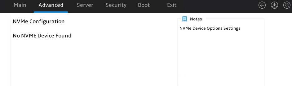
Table 68 Items on the NVMe Configuration submenu screen
|
Item |
Description |
|
Slot 61: INTEL SSDPE2KX010T7 |
Submenu for the selected installed NVMe device. |
SATA Configuration submenu
Figure 86 shows the SATA Configuration submenu screen, on which you can view information for connected SATA devices. The submenu items are described in Table 69.
Figure 86 SATA Configuration submenu screen

Table 69 Items on the SATA Configuration submenu screen
|
Item |
Description |
|
SATA Controller |
Displays the segment ID, bus ID, device ID, and function ID of the SATA controller to identify it. |
|
Port x |
Displays the name of the connected SATA port x, which is dynamically obtained based on the hard disk connection status. If the port is not present, Not Present is displayed. |
Network Configuration submenu
Figure 87 shows the Network Configuration submenu screen, on which you can configure the PXE settings for network ports. The submenu items are described in Table 70.
Figure 87 Network Configuration submenu screen
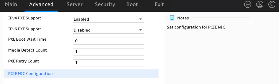
Table 70 Items on the Network Configuration submenu screen
|
Item |
Description |
Default |
|
IPv4 PXE Support |
Select Enabled or Disabled to enable or disable loading the OS over an IPv4 network using PXE. If Disabled is selected, the IPv4 PXE boot option will not be created. |
Enabled |
|
IPv4 HTTP Support |
Select Enabled or Disabled to enable or disable loading the OS over an IPv4 network using HTTP. If Disabled is selected, the IPv4 HTTP boot option will not be created. |
Disabled |
|
IPv6 PXE Support |
Select Enabled or Disabled to enable or disable loading the OS over an IPv6 network using PXE. If Disabled is selected, the IPv6 PXE boot option will not be created. |
Disabled |
|
IPv6 HTTP Support |
Select Enabled or Disabled to enable or disable loading the OS over an IPv6 network using HTTP. If Disabled is selected, the IPv6 HTTP boot option will not be created. |
Disabled |
|
IPv6 DUID Type |
Select the IPv6 DUID type. Options: · DUID-LLT. · DUID-UUID. |
DUID-LLT |
|
IPSEC Certificate |
Select whether to enable IPsec certificate. Options: · Enabled. · Disabled. |
Disabled |
|
PXE Boot Wait Time |
Set the wait time to press ESC key to abort the PXE boot. Value range: 0 to 5, in seconds. |
0 |
|
Media Detect Count |
This item is not available in Legacy mode. Set the maximum number of media presence detections. Value range: 1 to 50. |
1 |
|
PXE Retry Count |
Set the maximum number of PXE retries. Value range: 0 to 50. A value of 0 indicates that the number of PXE retries is not limited. |
1 |
|
UEFI PXE Disable Type |
Set the UEFI PXE type to be disabled. Options: · Skip Action. · Skip Driver. |
Skip Action |
|
PCIE NIC Configuration |
Submenu for configuring PCIe NIC settings, as shown in Figure 88. The submenu items are described in Table 71. |
N/A |
PCIE NIC Configuration submenu
Figure 88 shows the PCIE NIC Configuration submenu screen, on which you can configure the items described in Table 71.
Figure 88 PCIE NIC Configuration submenu screen
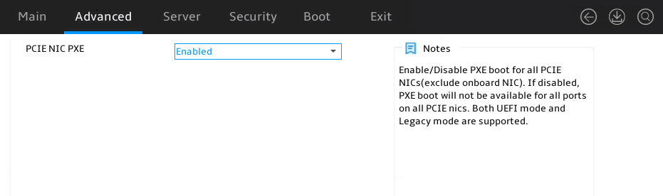
Table 71 Items on the PCIE NIC Configuration submenu screen
|
Item |
Description |
Default |
|
PCIE NIC PXE |
Select Enabled or Disabled to enable or disable PCIe NIC PXE. |
Enabled |
|
NIC X Port Y PXE |
Select Enabled or Disabled to enable or disable PXE on a specific NIC port. |
Enabled |
Miscellaneous Configuration submenu
Figure 89 shows the Miscellaneous Configuration submenu screen. The submenu items are described in Table 72.
Figure 89 Miscellaneous Configuration submenu screen
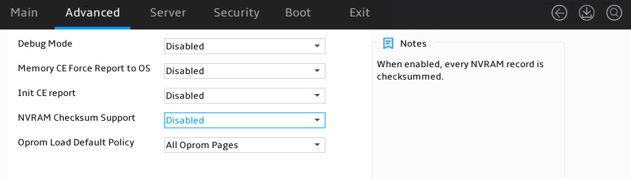
Table 72 Items on the Miscellaneous Configuration submenu screen
|
Item |
Description |
Default |
|
Debug Mode |
Select Enabled or Disabled to enable or disable the server to output BIOS console log messages. |
Disabled |
|
Memory CE Force Report to OS |
Select Enabled or Disabled to enable or disable forcible report of memory CE to the OS. |
Disabled |
|
Init CE report |
Select Enabled or Disabled to enable or disable the report of correctable errors at the initialization stage. |
Disabled |
|
NVRAM Checksum Support |
Select Enabled or Disabled to enable or disable NVRAM checksum. If Enabled is selected, each NVRAM data will be checked. |
Disabled |
SMBIOS Configuration submenu
As shown in Figure 90, you can configure SMBIOS settings on the SMBIOS Configuration submenu. The submenu items are described in Table 73.
Figure 90 SMBIOS Configuration submenu screen
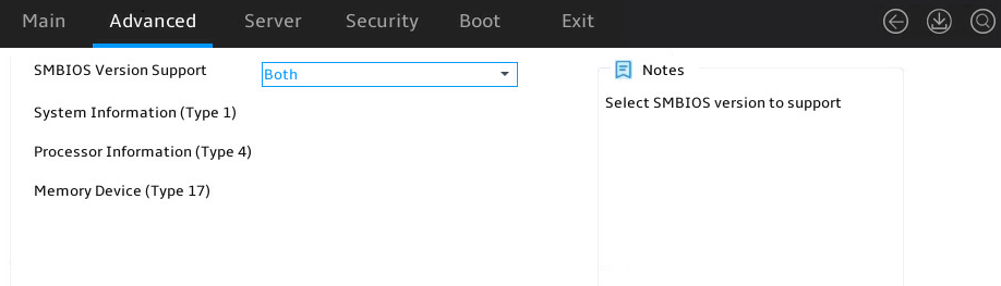
Table 73 Items on the SMBIOS Configuration submenu screen
|
Item |
Description |
Default |
|
SMBIOS Version Support |
Select the versions supported by SMBIOS. Options: · Both. · 2.X. · 3.X. |
Both |
|
System Information (Type 1) |
Submenu for configuring the system information. |
N/A |
|
Processor Information (Type 4) |
Submenu for configuring the processor information. |
N/A |
|
Memory Device (Type 17) |
Submenu for configuring the memory driver. |
N/A |
System Information submenu
As shown in Figure 91, the System Information submenu contains the items described in Table 74.
Figure 91 SMBIOS Configuration submenu screen
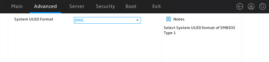
Table 74 Items on the SMBIOS Configuration submenu screen
|
Item |
Description |
Default |
|
System UUID Format |
Select the system UUID format. Options: · IPMI. · SMBIOS. |
IPMI |
Processor Information submenu
As shown in Figure 92, the Processor Information submenu contains the items described in Table 75.
Figure 92 Processor Information submenu screen
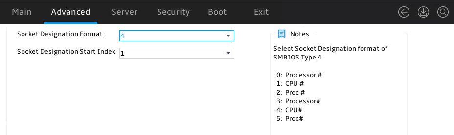
Table 75 Items on the Processor Information submenu screen
|
Item |
Description |
Default |
|
Socket Designation Format |
Select a socket designation format. Options: · 0. · 1. · 2. · 3. · 4. · 5. |
4 |
|
Socket Designation Start Index |
Select a socket designation start index. Options include: · 0. · 1. |
1 |
Memory Device submenu
As shown in Figure 93, the Memory Device submenu contains the items described in Table 76.
Figure 93 Memory Device submenu screen
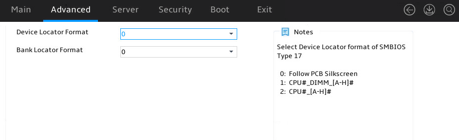
Table 76 Items on the Memory Device submenu screen
|
Item |
Description |
Default |
|
Device Locator Format |
Select the device locator format. Options: · 0. · 1. · 2. |
0 |
|
Socket Start Index |
Select the socket start index. Options: · 0. · 1. This item is available only when Device Locator Format is set to 1. |
0 |
|
DIMM Start Index |
Select the DIMM start index. Options: · 0. · 1. This item is available only when Device Locator Format is set to 1. |
0 |
|
Bank Locator Format |
Select the memory bank locator format. Options: · 0. · 1. · 2. |
0 |
AMD Mem Configuration Status submenu
As shown in Figure 94, you can view the health status of drives or controllers on the AMD Mem Configuration Status submenu screen. The submenu items are described in Table 77.
Figure 94 AMD Mem Configuration Status submenu screen
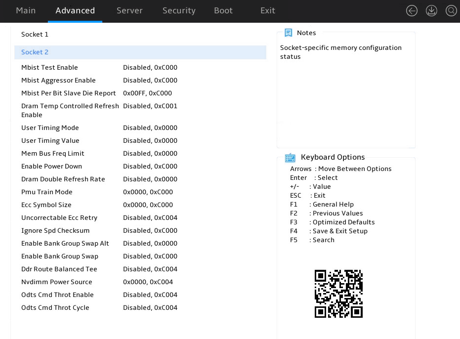
Table 77 Items on the AMD Mem Configuration Status submenu screen
|
Item |
Description |
|
socket X |
Submenu for configuring socket X. |
|
Mbist Test Enable |
Displays the enabling status for MBIST test. |
|
Mbist Aggressor Enable |
Displays the enabling status for MBIST Aggressor test. |
|
Mbist Per Bit Slave Die Report |
Displays the report for each bit of the slave dies in MBIST. |
|
Dram Temp Controlled Refresh Enable |
Displays the enabling status for the temperature-controlled refresh function in DRAM. |
|
User Timing Mode |
Displays the user timing mode. |
|
User Timing Value |
Displays the user timing value. |
|
Mem Bus Freq Limit |
Displays the memory bus frequency limit. |
|
Enable Power Down |
Displays the enabling status for Enable Power Down. |
|
Dram Double Refresh Rate |
Displays the DRAM double refresh rate. |
|
Pmu Train Mode |
Displays the PMU training mode. |
|
Ecc Symbol Size |
Displays the size of the error correction symbol. |
|
Uncorrectable Ecc Retry |
Displays the uncorrectable error correction retry settings. |
|
Ignore Spd Checksum |
Displays the SPD checksum ignoring settings. |
|
Enable Bank Group Swap Alt |
Displays the Enable Bank Group Swap Alt settings. |
|
Enable Bank Group Swap |
Displays the Enable Bank Group Swap settings. |
|
Ddr Route Balanced Tee |
Displays the Ddr Route Balanced Tee settings. |
|
Nvdimm Power Source |
Displays the NVDIMM power source. |
|
Odts Cmd Throt Enable |
Displays the Odts Cmd Throt Enable settings. |
|
Odts Cmd Throt Cycle |
Displays the Odts Cmd Throt Cycle settings. |
As shown in Figure 95, the Socket 1 submenu contains the items described in Table 78.
Figure 95 Socket 1 submenu screen
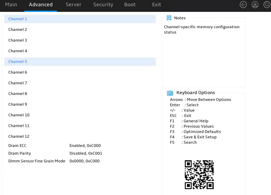
Table 78 Items on the Socket 1 submenu screen
|
Item |
Description |
|
Channel X |
Submenu for configuring Channel X. |
|
Dram ECC |
Displays the DRAM ECC information. |
|
Dram Parity |
Displays the DRAM parity information. |
|
Dimm Sensor Fine Grain Mode |
Displays the DRAM sensor fine grain mode. |
As shown in Figure 96, the Channel 1 submenu contains the items described in Table 79.
Figure 96 Channel 1 submenu screen
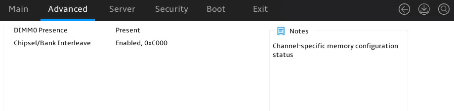
Table 79 Items on the Channel 1 submenu screen
|
Item |
Description |
|
DIMM0 Presence |
Displays the DIMM0 presence information. |
|
Chipsel/Bank Interleave |
Displays the enabling status for chipsel/bank interleaving. |
Server menu
Figure 97 shows the Server menu. From the menu, you can access the firmware information menu, and configure server management features such as the FRB-2 timer, OS watchdog timer, firmware information, HDM network configuration, and HDM user settings.
The menu items are described in Table 80.
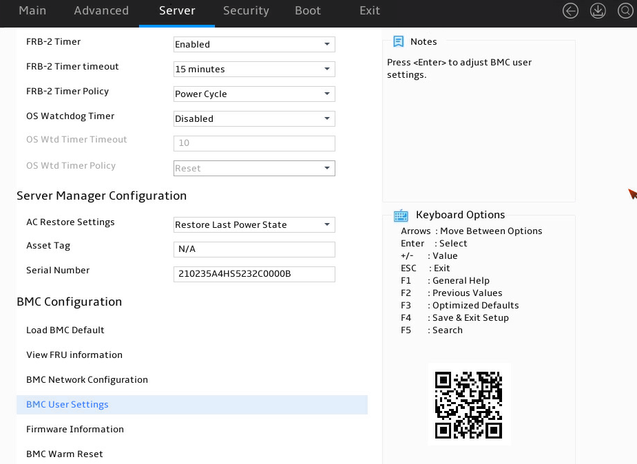
Table 80 Items on the Server menu screen
|
Item |
Description |
Default |
|
FRB-2 Timer |
Select Enabled or Disabled to enable or disable the FRB-2 timer. |
Enabled |
|
FRB-2 Timer Timeout |
Set the timeout for the FRB-2 timer. Options: · 3 Minutes. · 4 Minutes. · 5 Minutes. · 6 Minutes. · 10 Minutes. · 15 Minutes. · 20 Minutes. This item is available only when FRB-2 Timer is set to Enabled. Otherwise, it is grayed out. |
15 Minutes |
|
FRB-2 Timer Policy |
Select the action to take when the FRB-2 timer expires. Options: · Do Nothing—No action is taken. · Reset—Reboots the system. · Power Down—Removes the main power from the system. · Power Cycle—Power cycles the system. This item is available only when FRB-2 Timer is set to Enabled. Otherwise, it is grayed out. |
Power Cycle |
|
OS Watchdog Timer |
Select Enabled or Disabled to enable or disable the OS Watchdog timer. With this feature enabled, the timer is started when the system enters the OS. This timer can help resume operation of the operating system if the system becomes unresponsive. |
Disabled |
|
OS Wtd Timer Timeout |
Set the timeout for the OS Watchdog timer, in the range of 5 to 30 minutes. This item is available only when OS Watchdog Timer is set to Enabled. |
10 minutes |
|
OS Wtd Timer Policy |
Select the action to take when the OS Watchdog timer expires. Options: · Do Nothing—No action is taken. · Reset—Reboots the system. · Power Down—Removes the main power from the system. · Power Cycle—Power cycles the system. This item is available only when OS Watchdog Timer is set to Enabled. |
Reset |
|
Server Manager Configuration The following are server management setting options: |
||
|
Restore On AC Power Loss |
Select the state to which the system is restored when the system AC power is restored. Options: · Always Remain Off—The system always returns to the power-off state. · Restore Last Power State—The system returns to the power state when AC power was lost. · Always Power On—The system always returns to the power-on state. The default state also depends on HDM settings. |
Restore Last Power State |
|
Asset Tag |
Enter an asses tag for the server, 0 to 48 bytes in length. The format must meet the HDM requirements. |
N/A |
|
Serial Number |
Enter a serial number for the server, 2 to 20 bytes in length. The format must meet the HDM requirements. |
N/A |
|
HDM Configuration The following are Hardware Device Management (HDM) software setting options: |
||
|
Load HDM Factory Reset |
To restore the factory default settings for HDM, select this item, and then press Enter. It takes one minute to restore the factory default HDM settings. After the restoration finishes, the server restarts automatically.
Do not configure HDM-related items before the server restarts. |
N/A |
|
FRU Information |
Access the submenu for viewing FRU information, as shown in Figure 98. The submenu items are described in Table 81. |
N/A |
|
HDM Network Configuration |
Access the network configuration submenu for HDM access, as shown in Figure 99. The submenu items are described in Table 82. |
N/A |
|
HDM User Settings |
Access the submenu for managing HDM user accounts, as shown in Figure 103. The submenu items are described in Table 86. |
N/A |
|
Firmware Information |
Displays firmware information submenu. |
N/A |
|
HDM Warm Reset |
Displays HDM warm reset information. |
N/A |
FRU Information submenu
Figure 98 shows the FRU Information submenu screen. The submenu items are described in Table 81.
Figure 98 FRU Information submenu screen
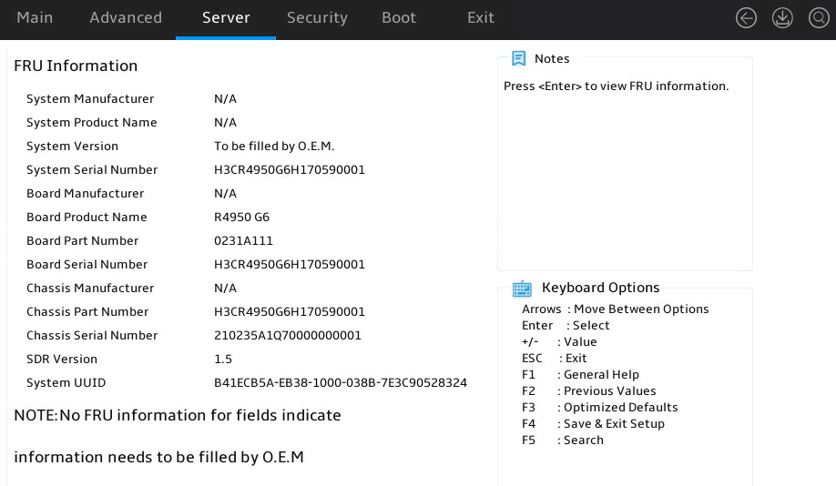
Table 81 Items on the FRU Information submenu screen
|
Item |
Description |
|
System Manufacturer |
Displays the manufacturer of the system. |
|
System Product Name |
Displays the name of the system product. |
|
System Version |
Displays the version of the system. |
|
System Serial Number |
Displays the serial number of the system. |
|
Board Manufacturer |
Displays the manufacturer of the system board. |
|
Board Product Name |
Displays the product name of the system board. |
|
Board Part Number |
Displays the part number of the system board. |
|
Board Serial Number |
Displays the serial number of the system board. |
|
Chassis Manufacturer |
Displays the manufacturer of the chassis. |
|
Chassis Version |
Displays the version of the chassis. |
|
Chassis Part Number |
Displays the part number of the chassis. |
|
Chassis Serial Number |
Displays the serial number of the system product. |
|
SDR Version |
Displays the SDR version. |
|
System Uuid |
Displays the UUID of the system. |
HDM Network Configuration submenu
Figure 99 shows the HDM Network Configuration submenu screen. The submenu items are described in Table 82.
Figure 99 HDM Network Configuration submenu screen
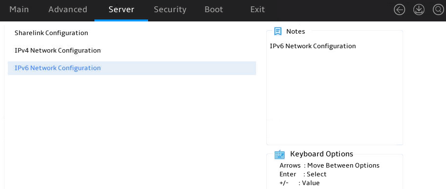
Table 82 Items on the HDM Network Configuration submenu screen
|
Item |
Description |
|
Sharelink Configuration |
Access the submenu for configuring the HDM sharelink. |
|
IPv4 Network Configuration |
Access the submenu for configuring the IPv4 network. |
|
IPv6 Network Configuration |
Access the submenu for configuring the IPv6 network. |
Sharelink Configuration submenu
Figure 100 shows the Sharelink Configuration submenu screen. Sharelink can be used for remote server management. You can log in to the HDM via the network for server information collection and management. The submenu items are described in Table 83.
Figure 100 Sharelink Configuration submenu screen

Table 83 Items on the Sharelink Configuration submenu screen
|
Item |
Description |
|
NCSI Network Setting |
Select HDM NCSI network port. This item is available when an NCSI-capable network adapter is installed on the server. You can select any network port of the present NCSI-capable network adapter. |
IPv4 Network Configuration submenu
The HDM shared network port and the HDM dedicated network port have the same parameters. The IP addresses of these ports cannot be in the same segment. The following takes the HDM dedicated network port for example.
Figure 101 shows the IPv4 Network Configuration submenu screen, on which you can view IPv4 network configuration information. The menu items are described in Table 84.
Figure 101 IPv4 Network Configuration submenu screen
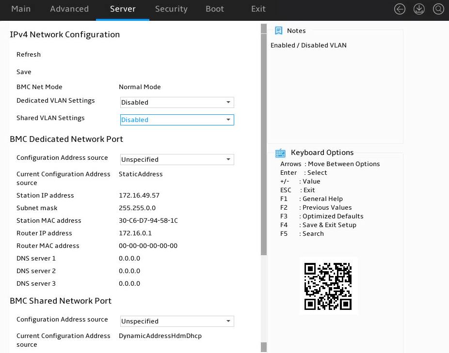
Table 84 Items on the IPv4 Network Configuration submenu screen
|
Item |
Description |
Default |
|
Refresh |
Refresh the HDM network configuration information. Press Enter to refresh configuration before making any changes. |
N/A |
|
Save |
Save settings. The saved settings takes effect immediately and you do not need to reboot. |
N/A |
|
HDM Net Mode |
Displays the HDM network mode dynamically. Options: · Normal Mode—In this mode, the HDM can be accessed through the HDM shared network port or the HDM dedicated network port. · Active/standby Mode—In this mode, the HDM dedicated port is used as the first choice to access the HDM. · Bonding Mode—In this mode, the HDM shared network port and the HDM dedicated network port are used as one logical network port. |
N/A |
|
Dedicated VLAN Setting |
Select Enabled or Disabled to enable or disable VLAN on the HDM dedicated network port. |
Disabled |
|
Dedicated VLAN id |
This item is available only when Dedicated VLAN Setting is set to Enabled. Configures the VLAN ID, in the range of 0 to 4094. |
0 |
|
Dedicated VLAN priority |
This item is available only when Dedicated VLAN Setting is set to Enabled. Specify the priority of a dedicated VLAN, in the range of 0 to 7. The larger the number, the higher the priority. When traffic congestion occurs, frames with the highest priority will be sent first. |
0 |
|
Shared VLAN Settings |
Select Enabled or Disabled to enable or disable VLAN on the HDM shared network port. |
Disabled |
|
Shared VLAN id |
This item is available only when Shared VLAN Setting is set to Enabled. Configures the VLAN ID, in the range of 0 to 4094. |
0 |
|
Shared VLAN priority |
This item is available only when Shared VLAN Setting is set to Enabled. Specify the priority of a shared VLAN, in the range of 0 to 7. The larger the number, the higher the priority. When traffic congestion occurs, frames with the highest priority will be sent first. |
0 |
|
HDM Dedicated / Shared Network Port |
||
|
Configuration Address source |
Configure the HDM network status parameters. Options: · Unspecified—Retains the current configuration. · Static—Uses manually specified configuration. · DynamicHdmDhcp—Uses network information obtained through DHCP. |
Unspecified |
|
Current Configuration Address source |
Displays the current address source. |
N/A |
|
Station IP Address |
This item is available only when Configuration Address source is set to Static. The configured HDM static IPv4 address takes effect only after both the Station IP Address and Subnet Mask are configured. Specify the station IP address for the port. |
N/A |
|
Subnet Mask |
This item is available only when Configuration Address source is set to Static. This item must be specified before you set the HDM static IPv4 address. Specify the subnet mask. |
0.0.0.0 |
|
Station MAC Address |
Displays the MAC address of the port. |
N/A |
|
Router IP Address |
This item is available only when Configuration Address source is set to Static. Specify the gateway IP address. |
N/A |
|
Router MAC Address |
Displays the gateway MAC address. |
N/A |
IPv6 Network Configuration submenu
The HDM shared network port and the HDM dedicated network port have the same parameters. The IP addresses of these ports cannot be in the same segment. The following takes the HDM dedicated network port for example.
Figure 102 shows the IPv6 Network Configuration submenu screen, on which you can view IPv4 network configuration information. The menu items are described in Table 85.
Figure 102 IPv6 Network Configuration submenu screen
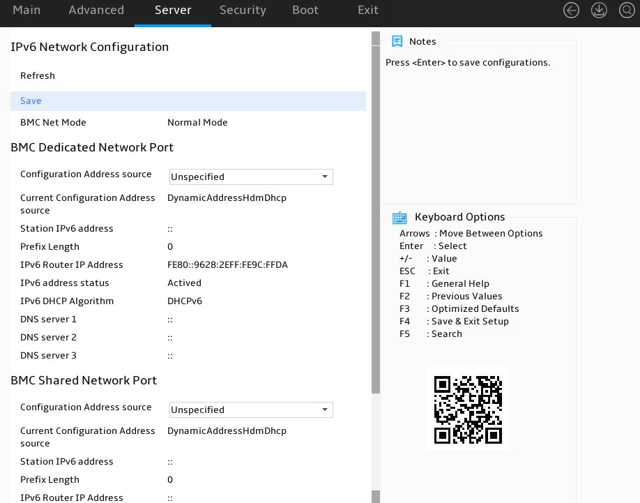
Table 85 Items on the IPv6 Network Configuration submenu screen
|
Item |
Description |
Default |
|
Refresh |
Refresh HDM network configuration information. Press Enter to refresh configuration before making any changes. |
N/A |
|
Save |
Save settings. The saved settings takes effect immediately and you do not need to reboot. |
N/A |
|
HDM Net Mode |
Displays the HDM network mode dynamically. Options: · Normal Mode—In this mode, the HDM can be accessed through the HDM shared network port or the HDM dedicated network port. · Active/standby Mode—In this mode, the HDM dedicated port is used as the first choice to access the HDM. |
N/A |
|
HDM Dedicated / Shared Network Port |
||
|
Configuration Address source |
Configure the HDM network status parameters. Options: · Unspecified—Retains the current configuration. · Static—Uses manually specified configuration. · DynamicHdmDhcp—Uses network information obtained through DHCP. |
Unspecified |
|
Current Configuration Address source |
Displays the current address source. |
N/A |
|
Station IP Address |
This item is available only when Configuration Address source is set to Static. The configured HDM static IPv6 address takes effect only after both the Station IPv6 Address and Prefix Length are configured. Specify the IPv6 address for the port. |
N/A |
|
Prefix Length |
This item is available only when Configuration Address source is set to Static. This item must be specified before you set the HDM static IPv6 address. Specify the prefix length, in the range of 0 to 127. 0 indicates that no prefix length is specified. |
0 |
|
IPv6 Router IP Address |
This item is available only when Configuration Address source is set to Static. The IPv6 gateway IPv6 address and the port IPv6 address must be in the same segment. Specify the IPv6 gateway IP address. |
N/A |
|
IPv6 address status |
Displays the status of the IPv6 address. |
N/A |
|
IPv6 DHCP Algorithm |
Displays the IPv6 DHCP algorithm. |
N/A |
HDM User Settings submenu
Figure 103 shows the HDM User Settings menu screen, on which you can configure HDM users. The menu items are described in Table 86.
Figure 103 HDM User Settings submenu screen
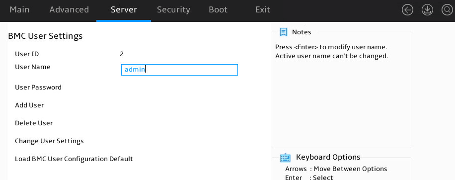
Table 86 Items on the HDM User Settings submenu screen
|
Item |
Description |
Default |
|
User ID |
Displays the HDM user ID. |
N/A |
|
User Name |
Press Enter to modify the HDM username. A username is a case-sensitive string of 1 to 16 characters and supports only letters, digits, and underscores (_). The name of the login user cannot be modified. |
N/A |
|
User Password |
Set the HDM user password. The password must follow these HDM password complexity check rules: · When password complexity check is enabled: ¡ The password must be a case-sensitive string of 8 to 20 characters and can contain only letters, digits, spaces, and special characters: `~!@#$%^&*()_+-=[]\{}|;':",./<>? ¡ It must contain at least two kinds of characters: uppercase letters, lowercase letters or numbers. ¡ It must contain at least one space or special character. ¡ It cannot be the same as the username or the reverse order of the username. · When password complexity check is disabled, the password must be a case-sensitive string of 2 to 20 characters and can contain only letters, digits, spaces, and the following special characters: `~!@#$%^&*()_+-=[]\{}|;':",./<>? By default, password complexity check is enabled. For more information about how to enable or disable password complexity check, see HDM online help. |
N/A |
|
Add User |
Add users. |
|
|
Delete User |
Delete users. |
|
|
Change User Settings |
Change user settings, including user permissions, username, and user password. |
|
|
Load HDM User Configuration Default |
Restore the default HDM user configuration. If the default HDM user is online, this feature is not available. |
N/A |
Firmware Information submenu
Figure 104 shows the Firmware Information submenu screen. The menu items are described in Table 87.
Figure 104 Firmware Information submenu screen
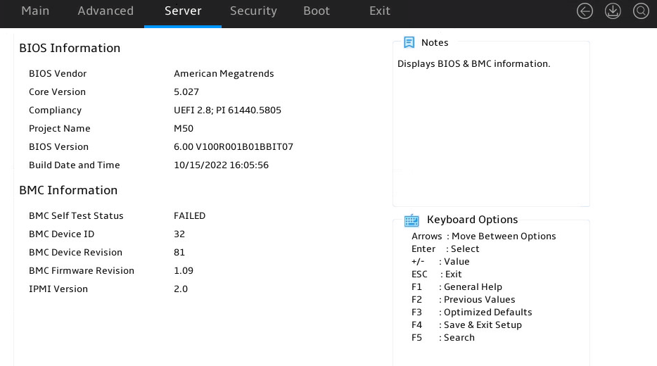
Table 87 Items on the Firmware Information submenu screen
|
Item |
Description |
|
BIOS Information |
|
|
BIOS Vendor |
Displays the BIOS vendor. |
|
Core Version |
Displays the core version. |
|
Compliancy |
Displays the BIOS compliance standard. |
|
Project Name |
Displays the project name. |
|
BIOS Version |
Displays the BIOS version. |
|
Build Date and Time |
Displays the BIOS build date and time. |
|
HDM Information |
|
|
HDM Self Test Status |
Displays the HDM self test status. |
|
HDM Device ID |
Displays the HDM device ID. |
|
HDM Device Revision |
Displays the HDM device revision. |
|
HDM Firmware Revision |
Displays the HDM firmware revision. |
|
IPMI Version |
Display the IPMI version. |
Security menu
Figure 105 shows the Security menu, on which you can configure security features such as setting the BIOS administrator and user passwords.
The menu items are described in Table 88.
|
|
NOTE: If you press F3 to restore defaults, the BIOS passwords do not change. |
Figure 105 Security menu screen
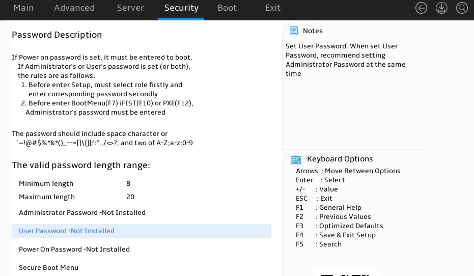
Table 88 Items on the Security menu screen
|
Item |
Description |
|
Password Description |
Displays the password description. |
|
Administrator Password |
Set the administrator password. For more information about restrictions for setting the administrator password, see "Restrictions and guidelines." |
|
User Password |
Set the user password. As a best practice, set the administrator password together with the user password. For more information about restrictions for setting the user password, see "Restrictions and guidelines." |
|
Power On Password |
Set the power-on password. For more information about restrictions for setting the power-on password, see "Restrictions and guidelines." |
|
HDD Security Configuration |
Displays hard disk drives that support security configuration, for example, P2:TS256GMTS800. To configure security settings for a hard disk drive, select the disk drive and press Enter. |
|
P2:TS256GMTS800 |
Security configuration page for hard disk drive P2:TS256GMTS800. |
|
Secure Boot Menu |
This item is available only in UEFI boot mode. Access the submenu for configuring secure boot, as shown in Figure 106. The submenu items are described in Table 89. |
Figure 106 shows the Secure Boot submenu screen. The submenu items are described in Table 89.
Secure boot is available only in UEFI mode. With this feature enabled, key authentication is required when you load any operating system or hardware driver program. This prevents intrusion of malware. The servers come with a secure boot key and you can import keys as needed. Secure boot does not require any hardware such as TPMs.
|
|
NOTE: If you press F3 to restore defaults, the setting in the Secure Boot Mode field will be restored to default and other settings will not change. |
Figure 106 Secure Boot submenu screen
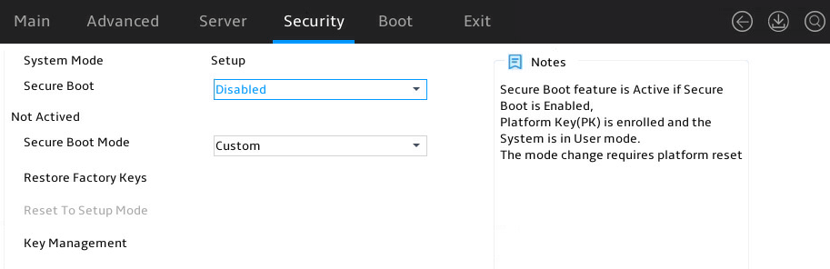
Table 89 Items on the Secure Boot menu screen
|
Item |
Description |
Default |
|
System Mode |
Displays the system mode. |
N/A |
|
Secure Boot |
Select Enabled or Disabled to enable or display secure boot. With this feature enabled, key authentication is required to load any operating system or hardware driver. Options: · Disabled—Disables the Secure Boot. · Enabled—Enables the Secure Boot. To enable Secure Boot, you must meet the following conditions: ¡ Platform Key (PK) has been registered. ¡ Secure Boot Mode is set to Custom mode. |
Disabled |
|
Secure Boot Mode |
Select a secure boot mode. Options: · Standard—Uses the preset secure boot key and certificate. In standard boot mode, you can select whether to install the factory default secure boot key. · Custom—In custom boot mode, you can configure the image execution policy and manage secure boot keys. |
Custom |
|
Restore Factory Keys |
Restore the factory default secure boot keys. |
N/A |
|
Reset To Setup Mode |
Reset the system mode to setup mode. |
N/A |
|
Key Management |
Access the submenu for key management, as shown in Figure 107. The submenu items are described in Table 90. |
N/A |
Figure 107 shows the Key Management submenu. The submenu items are described in Table 90.
Figure 107 Key Management submenu screen
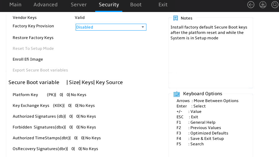
Table 90 Items on the Key Management submenu screen
|
Item |
Description |
Default |
|
Vendor Keys |
Displays whether the vendor keys have been modified. Options: · Valid—The vendor keys have not been modified and are valid. · Modified—The vendor keys have been modified or deleted. |
N/A |
|
Factory Key Provision |
Select Enabled or Disabled to enable or disable provisioning the factory default keys when the system is in setup mode. |
Disabled |
|
Restore Factory Keys |
Access the submenu for restoring factory default keys. This operation forces the system to enter user mode and installs factory default secure boot keys. |
N/A |
|
Reset To Setup Mode |
Access the submenu for resetting the system mode to setup mode. |
N/A |
|
Export Secure Boot Variables |
Access the submenu for exporting all secure boot variables. |
N/A |
|
Enroll Efi Image |
Access the submenu for enrolling the EFI image. This operation enables secure boot for the image and enrolls a SHA256 hash of the PE image in the Authorized Signature Database (DB). |
N/A |
|
Platform Key(PK) |
Access the submenu for managing the platform key. Option is Update. |
N/A |
|
Key Exchange Keys |
Access the submenu for managing key exchange keys. Options: · Update. · Append. |
N/A |
|
Authorized Signatures |
Access the submenu for configuring authorized signatures. Options: · Update. · Append. |
N/A |
|
Forbidden Signatures |
Access the submenu for managing forbidden signatures. Options: · Update. · Append. |
N/A |
|
Authorized TimeStamps |
Access the submenu for managing authorized timestamps. Options: · Update. · Append. |
N/A |
|
OsRecovery Signatures |
Access the submenu for configuring operating system recovery signatures. Options: · Update. · Append. |
N/A |
Boot menu
Figure 108 shows the Boot menu, on which you can configure boot settings such as the boot type and boot sequence.
The menu items are described in Table 91.
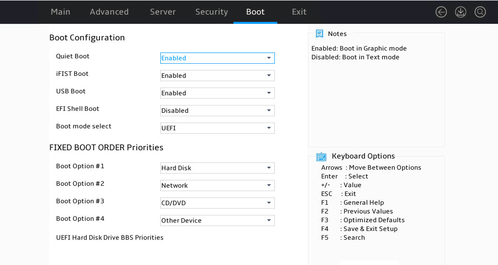
Table 91 Items on the Boot menu screen
|
Item |
Description |
Default |
|
Quiet Boot |
Select Enabled or Disabled to enable or disable quiet boot mode. Options: · Disabled—Enables the boot screen to display POST information during boot process, such as detailed version information and hardware information. · Enabled—Enables the boot screen to display the product logo instead of POST information during boot process. |
Enabled |
|
iFIST Boot |
Select Enabled or Disabled to enable or disable iFIST boot. If iFIST boot is disabled, the iFist item is not displayed on the BIOS startup screen as shown in Figure 2, and pressing F10 cannot boot iFIST. |
Enabled |
|
USB Boot |
Select Enabled or Disabled to enable or disable USB boot. |
Enabled |
|
EFI Shell Boot |
Select Enabled or Disabled to enable or disable shell boot. This item is not displayed if Boot Mode Select is set to LEGACY. |
Disabled |
|
Boot Mode Select |
Set the Boot mode selection options. Options: · LEGACY—Legacy boot mode. · UEFI—UEFI boot mode. Caution: If the OS is not installed in the target boot mode, switching the boot mode might cause the OS to fail to boot normally |
UEFI |
|
Fixed Boot Order Priorities The following options are for configuring the boot priority: |
||
|
Boot Option #1 |
Set the first boot option, select Disabled to disable boot items. |
N/A |
|
Boot Option #2 |
Set the second boot option, select Disabled to disable boot items. |
|
|
Boot Option #3 |
Set the third boot option, select Disabled to disable boot items. |
|
|
Boot Option #4 |
Set the fourth boot option, select Disabled to disable boot items. |
|
|
UEFI Hard Disk Drive BBS Priorities |
Access the submenu for configuring the boot priorities of hard disk drive, SD card, and USB-HDD, as shown in Figure 109. The submenu items are described in Table 92. This item is displayed in UEFI boot mode. |
N/A |
|
Hard Disk Drive BBS Priorities |
Access the submenu for configuring the boot priorities of hard disk drive, SD card, and USB-HDD. This item is displayed in legacy boot mode. |
N/A |
|
UEFI CDROM/DVD Drive BBS Priorities |
This item is displayed when one or more CD- or DVD-ROM drives are connected in UEFI boot mode. Access the submenu for configuring the boot priorities of connected CD- or DVD-ROM drives. |
N/A |
|
CDROM/DVD Drive BBS Priorities |
This item is displayed when one or more CD- or DVD-ROM drives are connected in legacy boot mode. Access the submenu for configuring the boot priorities of connected CD- or DVD-ROM drives. |
N/A |
|
UEFI Network Drive BBS Priorities |
Access the submenu for configuring the boot priorities of available network drives. This item is displayed in UEFI boot mode. |
N/A |
|
Network Drive BBS Priorities |
Access the submenu for configuring the boot priorities of available network drives. This item is displayed in legacy boot mode. |
N/A |
|
UEFI Other Drive BBS Priorities |
Set the boot device priority sequence from the available UEFI other drives. The options include but are not limited to: · Embedded UEFI shell. This option is available only when EFI Shell Boot is set to Enabled. · Other unidentified boot devices. |
N/A |
|
|
NOTE: The Fixed Boot Order Priorities list supports configuring only the overall boot order of different boot devices. If the server has more than one boot devices of the same type, to change the first boot device, enter the corresponding priorities submenu of the boot device, and then set the first boot option. The procedure is similar to that in "Setting the server boot order." For example, to change the first boot option for hard disks, enter the UEFI Hard Disk Drive BBS Priorities submenu, and then set the first boot option. |
UEFI Hard Disk Drive BBS Priorities submenu
As shown in Figure 109, the UEFI Hard Disk Drive BBS Priorities submenu displays the boot priority settings for UEFI Hard Disk Drive BBS. The displayed submenu items vary according to the configuration. Table 92 shows an example.
Figure 109 UEFI Hard Disk Drive BBS Priorities submenu screen
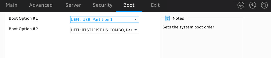
Table 92 Items on the UEFI Hard Disk Drive BBS Priorities submenu screen
|
Item |
Description |
|
Boot Option #X |
Select a hard disk as the X boot option. To disable this boot option, select Disabled. |
Exit menu
Figure 110 shows the Exit menu, on which you can modify BIOS parameter settings and exit the BIOS.
The menu items are described in Table 93.
Figure 110 Exit menu screen
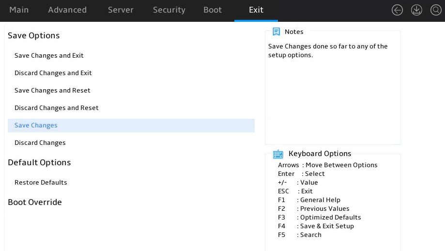
Table 93 Items on the Exit menu screen
|
Item |
Description |
|
Save Options |
|
|
Save Changes and Exit |
Exit with changes saved. |
|
Discard Changes and Exit |
Exit without saving changes. |
|
Save Changes and Reset |
Restart the server with changes saved. (Recommended) |
|
Discard Changes and Reset |
Restart the server without saving changes. |
|
Save Changes |
Save changes without exiting the BIOS. |
|
Discard Changes |
Discard changes without exiting the BIOS. |
|
Default Options |
|
|
Restore Defaults |
Restore the factory-default settings. |
|
Boot Override |
Select a boot device option and press Enter to boot from that device. This field displays all available boot options. This setting is a one-time setting that takes effect only at the next boot. Subsequent boots will use the boot order configured on the Boot menu screen. If you modify the BIOS Setup parameters without saving and then choose any boot option in the Boot Override field, a Save & Reset dialog box will open. In this dialog box, you can select either of the following options as needed: · Yes—The system will save the changes and reboot. However, it will not boot from the chosen option. · No—Cancel the modification. The dialog box will close automatically, and the system will not boot from the chosen option. For the system to immediately boot from a specific option, select Discard Changes in Figure 110 or pressing F2) and then choose any boot option in the Boot Override field. |
|
Windows Boot Manager(P2:Embedded:VK0240GDJXU) |
Operating system boot manager, displayed according to the actual situation. This item name is only an example. |
Acronyms and abbreviations
|
Term |
Definition |
|
A |
|
|
ACPI |
Advanced Configuration and Power Interface |
|
AHCI |
Advanced Host Controller Interface |
|
ARI |
Alternative Routing-ID |
|
ASPM |
Active State Power Management |
|
B |
|
|
BIOS |
Basic Input Output System |
|
C |
|
|
CCX |
Core Complex |
|
CSM |
Compatibility Support Module |
|
CRC |
Cyclic Redundancy Check |
|
D |
|
|
DF |
Data Fabric |
|
DMA |
Direct Memory Access |
|
DRAM |
Dynamic Random Access Memory |
|
E |
|
|
ECC |
Error Checking and Correcting |
|
EFI |
Extensible Firmware Interface |
|
EMS |
Emergency Management Services |
|
F |
|
|
FCH |
Server Controller Hub (SCH, also called FCH) |
|
G |
|
|
GPU |
Graphics Processing Unit |
|
H |
|
|
HBA |
Host Bus Adapter |
|
HDM |
Hardware Device Management |
|
IIO |
Integrated I/O Module |
|
L |
|
|
LTR |
Latency Tolerance Reporting |
|
M |
|
|
MAC |
Media Access Control |
|
MBIST |
Memory built-in self-test |
|
MMIO |
Memory mapping I/O |
|
N |
|
|
NBIO |
NorthBridge IO |
|
NIC |
Network Interface Controller |
|
NMI |
Non Maskable Interrupt |
|
NTB |
Non-Transparent Bridging |
|
NUMA |
Non Uniform Memory Access |
|
O |
|
|
ODT |
On-Die Termination |
|
OS |
Operating System |
|
PCI |
Peripheral Component Interface |
|
PCIe |
Peripheral Component Interconnect Express |
|
PECI |
Platform Environment Control Interface |
|
PK |
Platform Key |
|
POR |
Plan Of Record |
|
POST |
|
|
PSP |
Platform Security Processor |
|
PWM |
Pulse Width Modulation |
|
PXE |
Preboot Execute Environment |
|
R |
|
|
RAID |
Redundant Arrays of Independent Disks |
|
RAS |
Reliability, Availability, Serviceability |
|
ROM |
Read-Only Memory |
|
RTS/CTS |
Request To Send/Clear To Send |
|
S |
|
|
SAS |
Serial Attached SCSI |
|
SATA |
Serial Advanced Technology Attachment |
|
SCSI |
Small Computer System Interface |
|
SEL |
System Event Log |
|
SEV |
Secure Encrypted Virtualization |
|
SLIT |
System Locality Information Table |
|
SMI |
System Management Interrupt |
|
SMM |
System Management Mode |
|
SMT |
Simultaneous multithreading. |
|
SMU |
System Management Unit |
|
SRAT |
ACPI Static Resource Affinity Table |
|
SR-IOV |
Single-Root I/O Virtualization |
|
SMBIOS |
System Management BIOS |
|
SVM |
Secure virtual machine |
|
T |
|
|
TPM |
Trusted Platform Module |
|
TCM |
Trusted Computing Platform |
|
TDP |
Thermal Design Power |
|
TLP |
Transaction Layer Packet |
|
U |
|
|
UEFI |
Unified Extensible Firmware Interface |
|
UMC |
Unified Memory Controllers |
|
UID |
Unit Identification |
|
V |
|
|
VGA |
Video Graphics Array |
|
X |
|
|
eXtensible Host Controller Interface |
|
