- Table of Contents
- Related Documents
-
| Title | Size | Download |
|---|---|---|
| 01-Text | 10.96 MB |
Contents
General safety recommendations
Examining the installation site
Mounting the router on a workbench
Rack-mounting the router by using front mounting brackets
Rack-mounting the router by using front and rear mounting brackets
Rack-mounting the router by using front mounting brackets and slide rails
Grounding the router through the grounding terminal on the rack
Grounding the router with a grounding strip
Grounding the router with a grounding conductor buried in the earth ground
Installing an interface module
Connecting the router to the network
Logging in from the console port
Accessing the router for the first time
No response from the serial port
Interface module, cable, and connection failure
Restoring the factory settings
1 Preparing for installation
The MSR3600 router series includes the models in Table1-1.
Table1-1 MSR3600 router series models
|
Model (marked on the front panel) |
Product code |
|
H3C MSR 36-10 |
RT-MSR3610 |
|
RT-MSR3610-DC |
|
|
H3C MSR 36-20 |
RT-MSR3620 |
|
RT-MSR3620-DC |
|
|
RT-MSR3620-PoE |
|
|
H3C MSR3610 Series |
RT-MSR3610-G |
|
RT-MSR3610-X1 |
|
|
RT-MSR3610-XS |
|
|
RT-MSR3610-X1-DP |
|
|
RT-MSR3610-X1-DC |
|
|
RT-MSR3610-X1-DP-DC |
|
|
RT-MSR3610E-X1 |
|
|
RT-MSR3610E-X1-DP |
|
|
H3C MSR3620 Series |
RT-MSR3620-G |
|
RT-MSR3620-XS |
|
|
RT-MSR3620-X1 |
|
|
RT-MSR3620-X1-XS |
|
|
H3C MSR3620-DP |
RT-MSR3620-DP |
|
H3C MSR 36-40 |
RT-MSR3640 |
|
H3C MSR 36-60 |
RT-MSR3660 |
|
H3C MSR3640 Series |
RT-MSR3640-G |
|
RT-MSR3640-X1 |
|
|
RT-MSR3640-XS |
|
|
RT-MSR3640-X1-HI |
|
|
H3C MSR3660 Series |
RT-MSR3660-XS |
|
H3C MSR3600 |
RT-MSR3600-28 |
|
RT-MSR3600-51 |
|
|
H3C MSR3600 Series |
RT-MSR3600-28-SI |
|
RT-MSR3600-51-SI |
|
|
RT-MSR3600-28-SI-GL |
|
|
RT-MSR3600-28-X1 |
|
|
RT-MSR3600-51-X1 |
|
|
RT-MSR3600-28-X1-DP |
|
|
RT-MSR3600-51-X1-DP |
|
|
RT-MSR3600-28-XS |
|
|
RT-MSR3600-28-G-DP |
|
|
RT-MSR3600-51-G-DP |
Safety recommendations
Safety symbols
When reading this document, note the following symbols:
![]() WARNING means an alert that calls attention to important information that if
not understood or followed can result in personal injury.
WARNING means an alert that calls attention to important information that if
not understood or followed can result in personal injury.
![]() CAUTION means an alert that calls attention to important information that if
not understood or followed can result in data loss, data corruption, or damage
to hardware or software.
CAUTION means an alert that calls attention to important information that if
not understood or followed can result in data loss, data corruption, or damage
to hardware or software.
General safety recommendations
· Keep the chassis and installation tools away from walk areas.
· Make sure the ground is dry and flat and anti-slip measures are in place.
· Unplug all the external cables (including power cords) before moving the chassis.
Electricity safety
· Locate the emergency power-off switch in the room before installation. Shut the power off at once in case accident occurs. Disconnect the power cord of the router if necessary.
· Make sure the router is correctly grounded.
· Do not open or close the chassis cover when the router is powered on.
· Correctly connect the interface cables of the router.
· If there are two power inputs, disconnect the two power inputs to power off the router.
· Always make sure the power has been disconnected during the installation and replacement procedures.
Laser safety
· Do not stare into any fiber port when the router has power. The laser light emitted from the optical fiber might hurt your eyes.
· Install the dust cover if the fiber port is not connected to a fiber connector to prevent damage to the fiber port.
Examining the installation site
The router can only be used indoors. To make sure the router operates correctly and to prolong its service lifetime, the installation site must meet the following requirements.
Temperature and humidity
Maintain temperature and humidity in the equipment room at acceptable levels.
· Lasting high relative humidity tends to cause poor insulation, electricity leakage, mechanical property change of materials, and corrosion of metal parts.
· Lasting low relative humidity is likely to result in loose screws due to washer contraction, and even ESD, which causes the circuits to fail.
· A high temperature is the most undesirable condition, because it accelerates the aging of insulation materials and significantly lowers reliability and service life of the router.
For the temperature and humidity requirements of the router, see Table1-2.
Table1-2 Temperature and humidity requirements
|
Temperature |
Humidity |
|
0°C to 45°C (32°F to 113°F) (without disks) 5°C to 40°C (41°F to 104°F) (with disks) |
5% RH to 95% RH (noncondensing) |
Cleanliness
Dust buildup on the chassis might result in electrostatic adsorption, which causes poor contact of metal components and contact points, especially when indoor relative humidity is low. In the worst case, electrostatic adsorption can cause communication failure. Table1-3 describes the router requirement for cleanliness.
Table1-3 Router requirement for cleanliness
|
Substance |
Particle diameter |
Concentration limit |
|
Dust particles |
≥ 0.5 µm |
≤ 1.8 × 10⁷ particles/m3 |
Corrosive gases can accelerate corrosion and aging of metal components. Make sure the corrosive gases do not exceed the concentration limits as shown in Table1-4.
Table1-4 Corrosive gas concentration limits
|
Gas |
Average concentration (mg/m3) |
Maximum concentration (mg/m3) |
|
SO2 |
0.3 |
1.0 |
|
H2S |
0.1 |
0.5 |
|
Cl2 |
0.1 |
0.3 |
|
HCI |
0.1 |
0.5 |
|
HF |
0.01 |
0.03 |
|
NH3 |
1.0 |
3.0 |
|
O3 |
0.05 |
0.1 |
|
NOX |
0.5 |
1.0 |
Cooling system
The following routers use left to right airflow for heat dissipation:
· MSR 36-10
· MSR 36-20
· MSR3610-G
· MSR3610-X1
· MSR3610-XS
· MSR3610-X1-DP
· MSR3610-X1-DC
· MSR3610-X1-DP-DC
· MSR3610E-X1
· MSR3610E-X1-DP
· MSR3620-G
· MSR3620-X1
· MSR3620-X1-XS
· MSR3620-DP
· MSR3620-XS
· MSR3600-28
· MSR3600-28-SI
· MSR3600-28-SI-GL
· MSR3600-28-X1
· MSR3600-28-X1-DP
· MSR3600-28-XS
· MSR3600-51
· MSR3600-51-SI
· MSR3600-51-X1
· MSR3600-51-X1-DP
· MSR3600-28-G-DP
· MSR3600-51-G-DP
The following routers use left to rear airflow for heat dissipation:
· MSR 36-40
· MSR 36-60
· MSR3640-X1
· MSR3640-XS
· MSR3640-X1-HI
· MSR3660-XS
The MSR3640-G router uses left and front to rear airflow for heat dissipation.
Figure1-1 Airflow through the chassis (all routers except for MSR 36-40/MSR 36-60/MSR3640-X1/MSR3640-XS/MSR3640-X1-HI/MSR3640-G/MSR3660-XS routers)
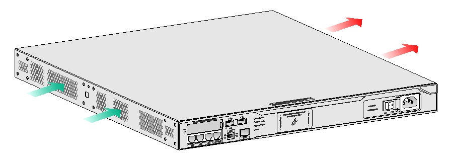
Figure1-2 Airflow through the chassis (MSR 36-40/MSR 36-60/MSR3640-X1/MSR3640-XS/MSR3640-X1-HI/MSR3660-XS routers)
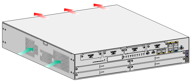
Figure1-3 Airflow through the chassis (MSR3640-G router)
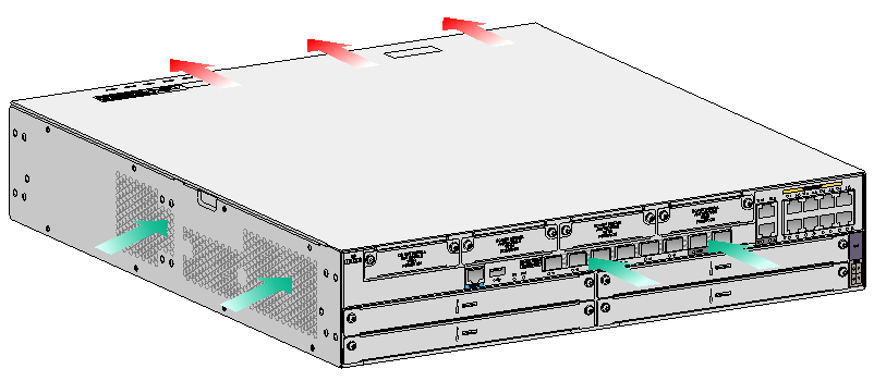
To ensure good ventilation, the following requirements must be met:
· The air inlet and outlet vents are not blocked, and leave at least 100 mm (3.94 in) of clearance.
· The installation site has a good cooling system.
ESD prevention
|
|
CAUTION: Check the resistance of the ESD wrist strap for safety. The resistance reading must be in the range of 1 to 10 megohm (Mohm) between human body and the ground. |
To prevent electrostatic discharge (ESD), follow these guidelines:
· Make sure the router and the floor are correctly grounded.
· Take dust-proof measures for the equipment room.
· Maintain the humidity and temperature at acceptable levels.
· Always wear an ESD wrist strap and ESD clothing when touching a circuit board or transceiver module.
The router does not supply an ESD wrist strap. Prepare an ESD wrist strap yourself.
· Place the removed CF card or interface module on an antistatic workbench, with the face upward, or put it into an antistatic bag.
· Touch only the edges, instead of electronic components when you observe or move a removed CF card or interface module.
To attach an ESD wrist strap:
1. Wear the wrist strap on your wrist.
2. Lock the wrist strap tight around your wrist to keep good contact with the skin.
3. Secure the wrist strap lock and the alligator clip lock together.
4. Attach the alligator clip to the rack or workbench where the router is installed.
5. Make sure the rack is correctly grounded.
EMI
Electromagnetic interference (EMI) might be coupled from the source to the router through the following coupling mechanisms:
· Capacitive coupling
· Inductive coupling
· Radiative coupling
· Common impedance coupling
· Conductive coupling
To prevent EMI, take the following actions:
· Take measures against interference from the power grid.
· Do not use the protection ground of the router together with the grounding equipment or lightning-prevention equipment of power equipment, and keep the router far away from them.
· Keep the router far away from high-power radio launchers, radars, and equipment with high frequency or high current.
· Use electromagnetic shielding when necessary.
Lightning protection
To better protect the router from lightning, do as follows:
· Make sure the grounding cable of the chassis is correctly grounded.
· Make sure the grounding terminal of the AC power receptacle is correctly grounded.
· Install a lightning arrester at the input end of the power supply to enhance the lightning protection capability of the power supply.
· Install a special lightning arrester at the input end of outdoor signal lines (for example, E1/T1 line) to which interface modules of the router are connected to enhance the lightning protection capability.
Rack-mounting
Before mounting the router in a standard 19-inch rack, adhere to the following requirements:
· The rack is equipped with a good ventilation system.
· The rack is sturdy enough to support the router and its accessories.
· For heat dissipation and device maintenance, make sure the front and rear of the rack are at least 0.8 m (2.62 ft) away from walls or other devices, and the headroom in the equipment room is no less than 3 m (9.84 ft).
Installation tools
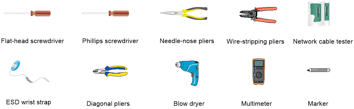
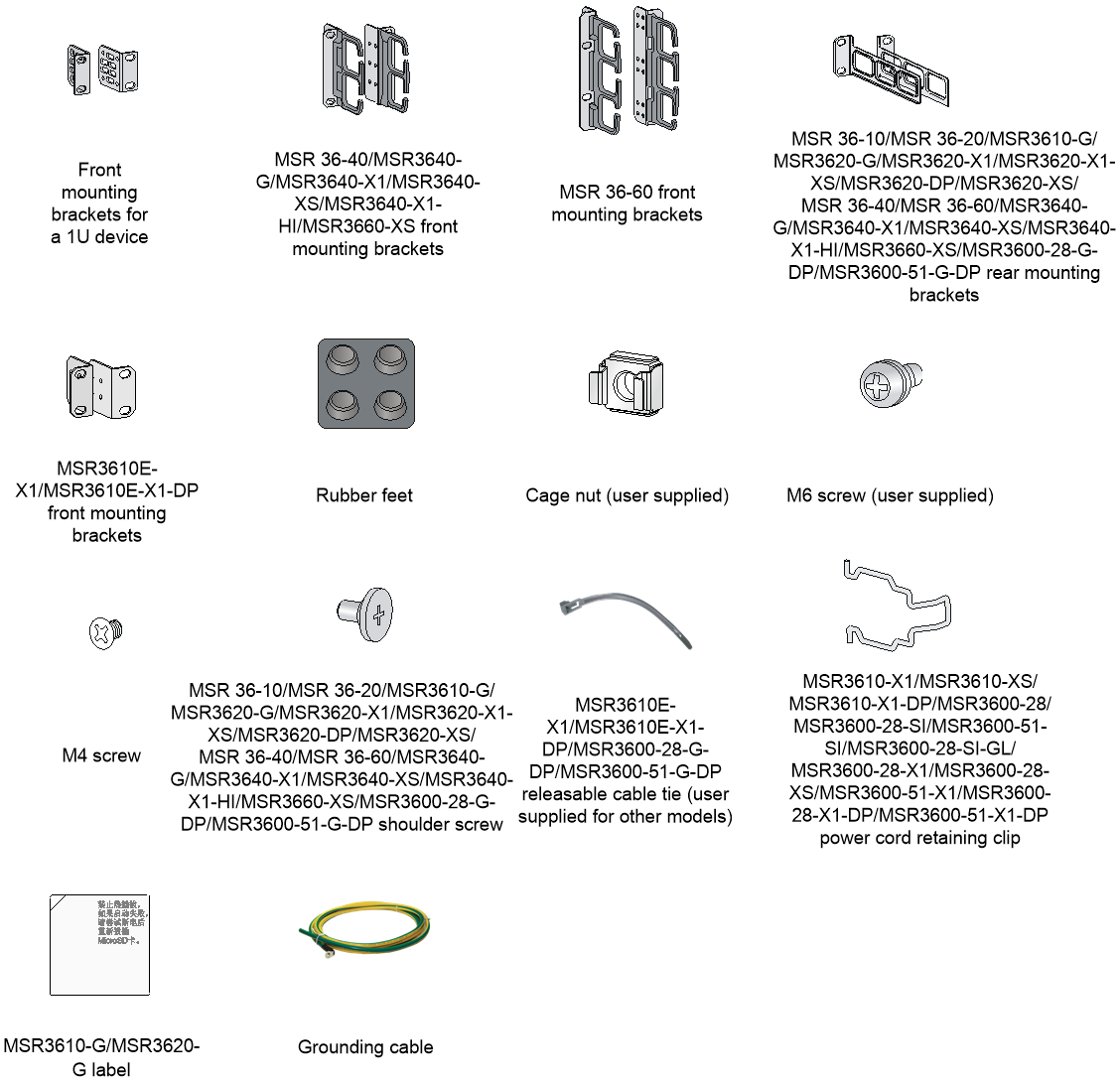
Installation accessories
Figure1-4 Installation accessories
Pre-installation checklist
Table1-5 Pre-installation checklist
|
Item |
Requirements |
Result |
|
|
Installation site |
Ventilation |
· There is a minimum clearance of 100 mm (3.94 in) around the inlet and outlet vents for heat dissipation of the router chassis. · A good ventilation system is available at the installation site. |
|
|
Temperature |
· 0°C to 45°C (32°F to 113°F) (without disks) · 5°C to 40°C (41°F to 104°F) (with disks) |
|
|
|
Relative humidity |
5% RH to 95% RH (noncondensing). |
|
|
|
Cleanliness |
· Dust concentration ≤ 1.8 × 10⁷ particles/m3. · No visible dust on desk within three days. |
|
|
|
ESD prevention |
· The equipment and floor are correctly grounded. · The equipment room is dust-proof. · The humidity and temperature are at acceptable levels, respectively. · Wear an ESD wrist strap and uniform when touching a circuit board. · Place the CF card or interface module on an antistatic workbench, with the face upward, or put it into an antistatic bag. · Touch only the edges, instead of electronic components when observing or moving a removed CF card or interface module. |
|
|
|
EMI prevention |
· Take effective measures to protect the power system from the power grid system. · Separate the protection ground of the router from the grounding device or lightning protection grounding device as far as possible. · Keep the router far away from radio stations, radar and high-frequency devices working in high current. · Use electromagnetic shielding when necessary. |
|
|
|
Lightning protection |
· The grounding cable of the chassis is correctly grounded. · The grounding terminal of the AC power receptacle is correctly grounded. · A port lightning arrester is installed. (Optional.) · A power lightning arrester is installed. (Optional.) · A signal lightning arrester is installed at the input end of an external signal cable. (Optional.) |
|
|
|
Electricity safety |
In case of emergency during operation, switch off the external power switch. |
|
|
|
Workbench |
· The workbench is stable enough. · The workbench is correctly grounded. |
|
|
|
Rack-mounting requirements |
· The rack is equipped with a good ventilation system. · The rack is sturdy enough to support the weight of the router and installation accessories. · The size of the rack is appropriate for the router. · The front and rear of the rack are at least 0.8 m (2.62 ft) away from walls or other devices. |
|
|
|
Safety precautions |
· The router is far away from any moist area and heat source. · The emergency power switch in the equipment room is located. |
|
|
|
Tools |
· Installation accessories supplied with the router. · User supplied tools. |
|
|
|
Reference |
· Documents shipped with the router. · Online documents. |
|
|
2 Installing the router
|
WARNING! To avoid injury, do not touch bare wires, terminals, or parts with high-voltage hazard signs. |
|
|
IMPORTANT: · The barcode on the router chassis contains product information that must be provided to local sales agent when you return a faulty router for service. · Keep the tamper-proof seal on a mounting screw on the chassis cover intact, and if you want to open the chassis, contact H3C for permission. Otherwise, H3C shall not be liable for any consequence. |
Installation prerequisites
· You have read "Preparing for installation" carefully.
· All requirements in "Preparing for installation" are met.
Installation flow
You can install the router on a workbench or in a rack. Select an installation method according to the installation environment, and follow the installation flowchart shown in Figure2-1.

Installing an air filter
No air filter is provided with the router. Purchase one yourself. Only the MSR 36-40, MSR 36-60, MSR3640-G, MSR3640-X1, MSR3640-XS, MSR3640-X1-H1, and MSR3660-XS routers support air filters.
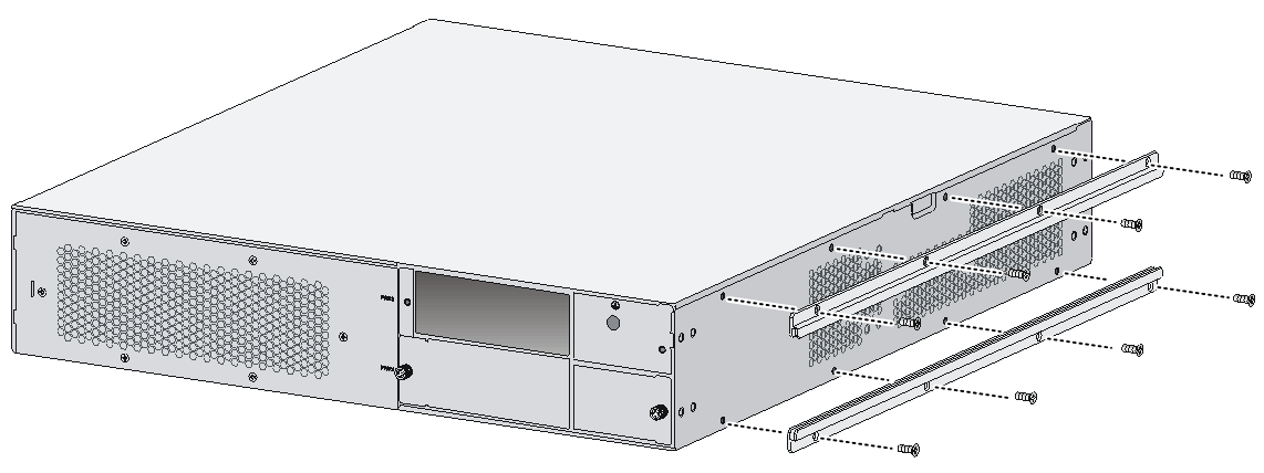
1. Face the left side (side of the inlet vents) of the router.
2. Install the upper and lower guide rails of the air filter to the chassis. Fasten the fastening screws on the guide rails with a Phillips screwdriver. See Figure2-2.
Figure2-2 Installing the upper and lower guide rails
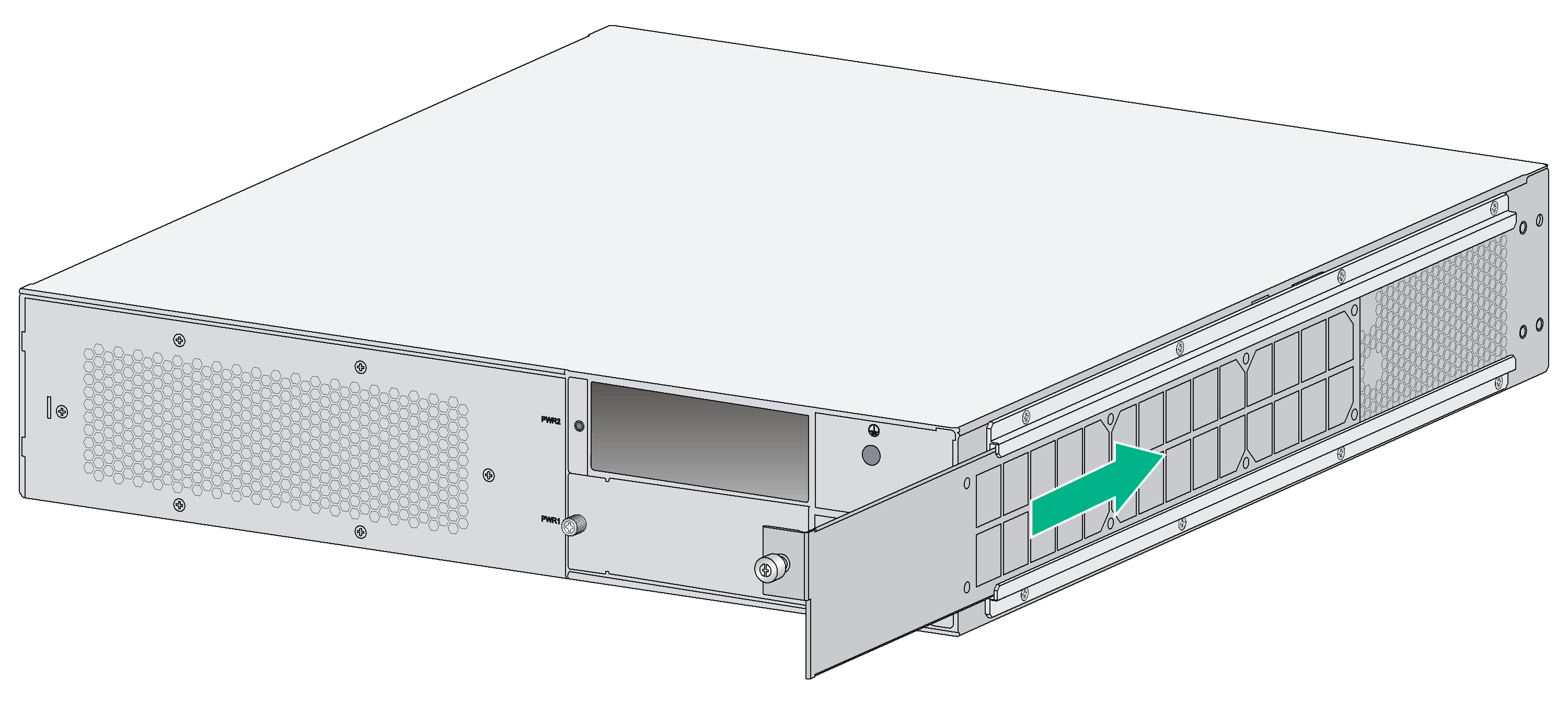
3. Push the air filter along the guide rails from the rear side of the chassis to the front.
Figure2-3 Pushing the air filter along the guide rails
4. Use a Phillips screwdriver to fasten the captive screw on the air filter.
Mounting the router on a workbench
|
|
IMPORTANT: · Ensure good ventilation and 100 mm (3.94 in) of clearance around the chassis for heat dissipation. · Do not place heavy objects on the router. |
To mount the router on a workbench:
1. Make sure the workbench is clean, stable, and correctly grounded.
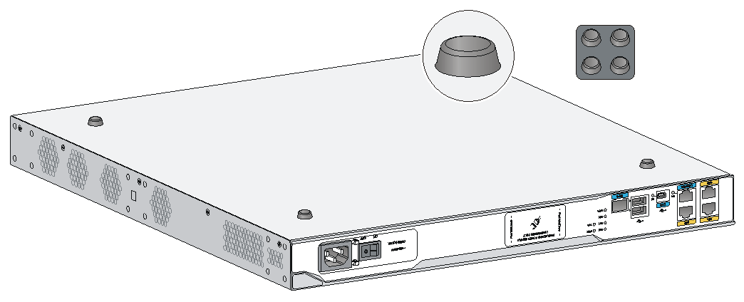
2. Place the router upside down on the workbench and attach the rubber feet to the four round holes in the chassis bottom.
Figure2-4 Attaching the rubber feet (MSR 36-10 AC)
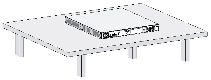
3. Place the router on the workbench with the upside up.
Figure2-5 Mounting the router on a workbench (MSR 36-10 AC)
Mounting the router in a rack
Router dimensions
Figure2-6 MSR 36-10/MSR 36-20 router dimensions
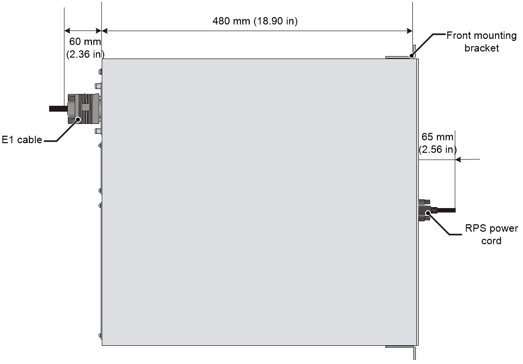
Figure2-7 MSR3610-G/MSR3620-G router dimensions
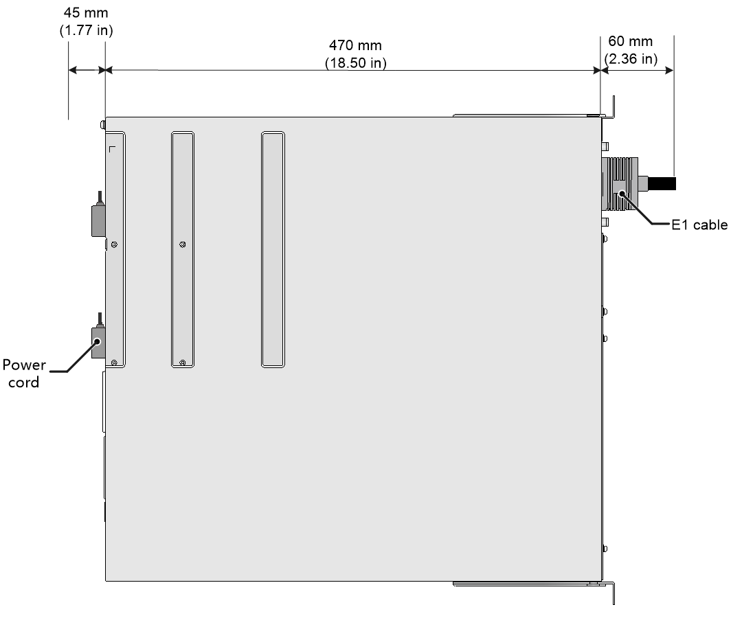
Figure2-8 MSR3620-X1/MSR3620-X1-XS/MSR3620-DP/MSR3620-XS router dimensions
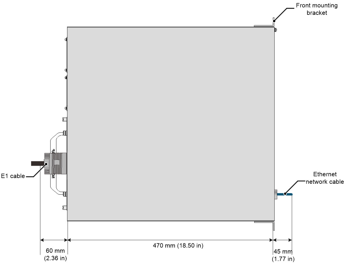
Figure2-9 MSR 36-40/MSR 36-60/MSR3640-G/MSR3640-X1/MSR3640-XS/MSR3640-X1-H1/MSR3660-XS router dimensions

Figure2-10 MSR3600-28/MSR3610-X1/MSR3610-XS/MSR3610-X1-DP/MSR3610-X1-DC/MSR3610-X1-DP-DC router dimensions
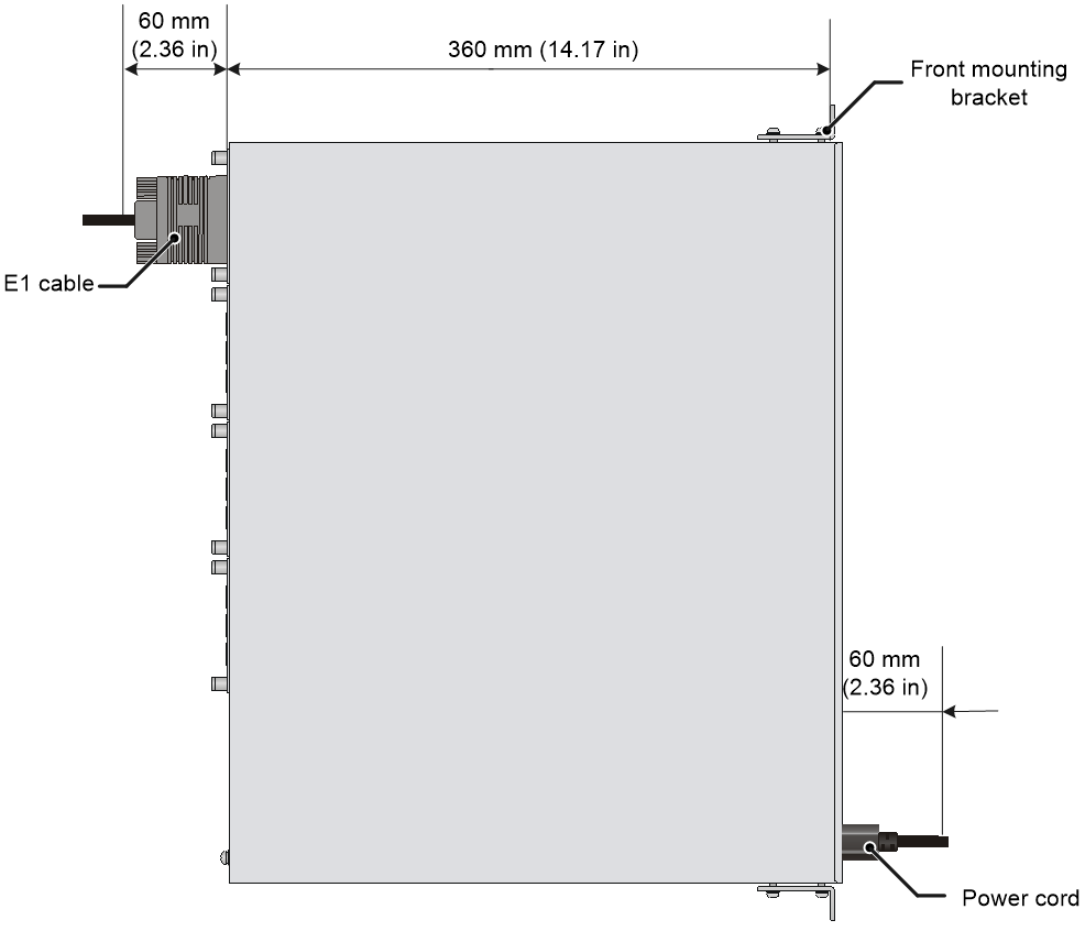
Figure2-11 MSR3610E-X1/MSR3610E-X1-DP router dimensions
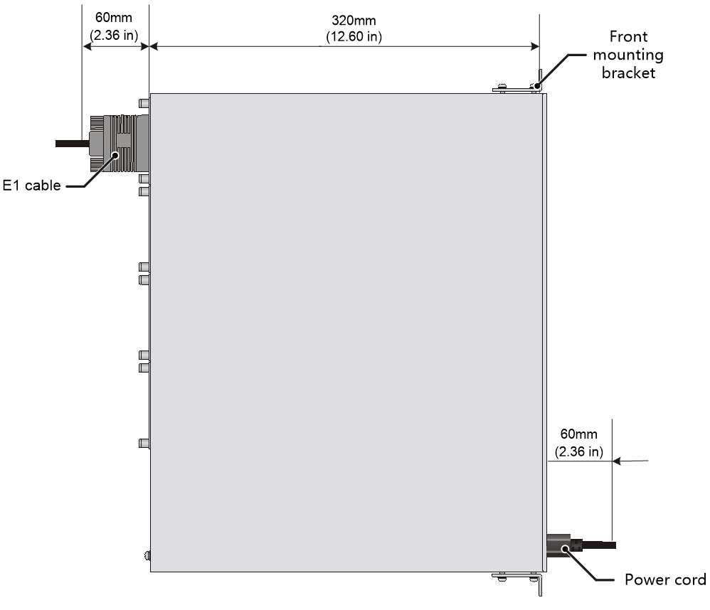
Figure2-12 MSR3600-28-SI/MSR3600-28-SI-GL router dimensions
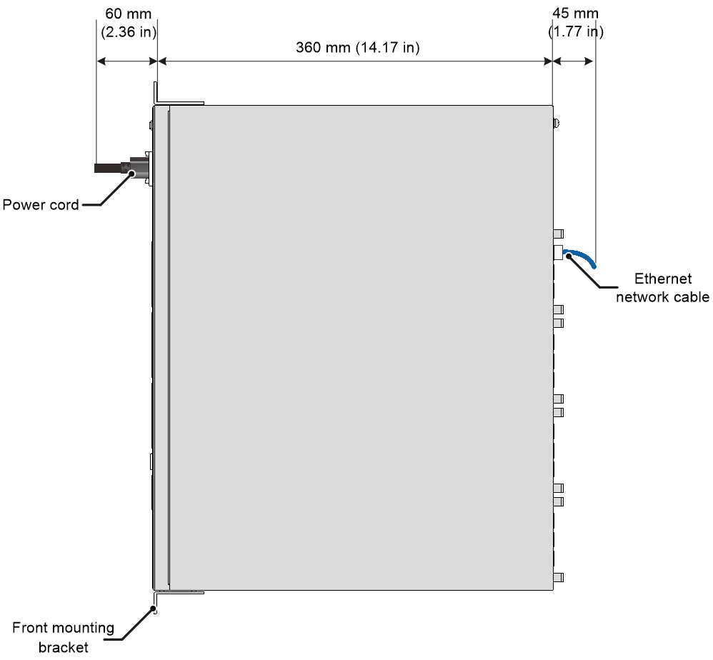
Figure2-13 MSR3600-28-X1/MSR3600-28-XS router dimensions
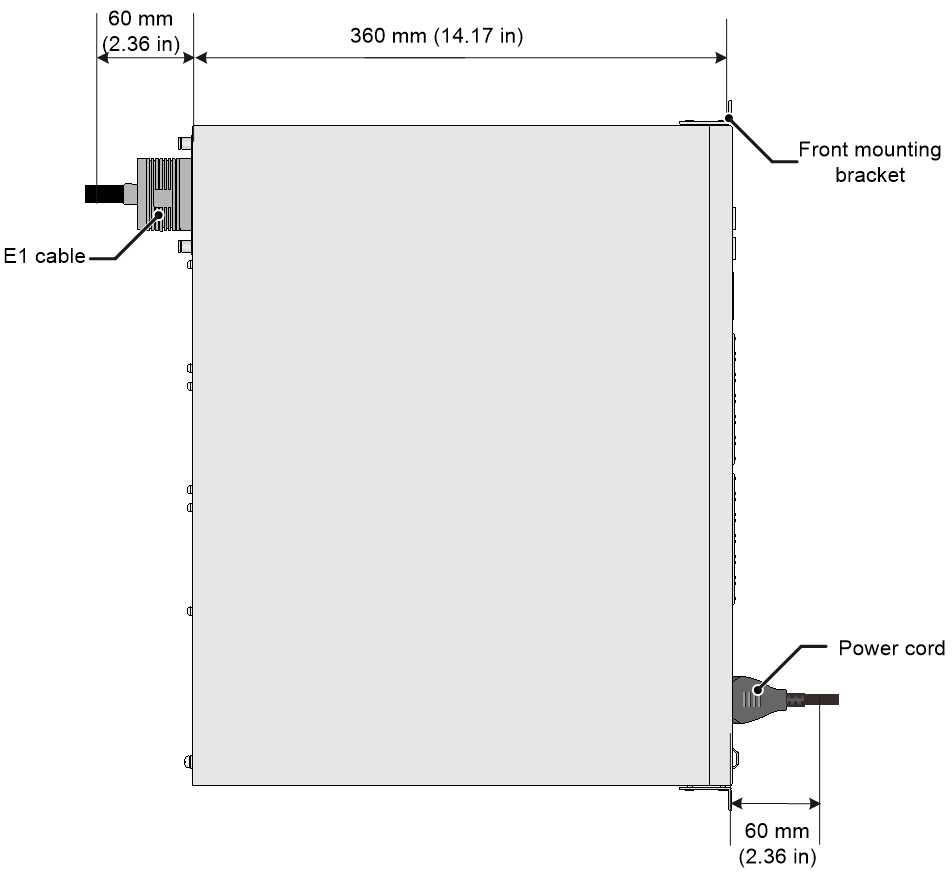
Figure2-14 MSR3600-28-X1-DP router dimensions

Figure2-15 MSR3600-51 router dimensions
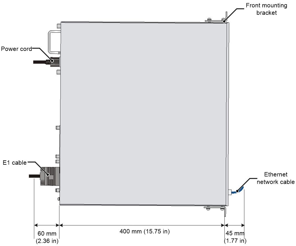
Figure2-16 MSR3600-51-SI router dimensions
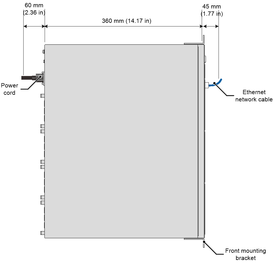
Figure2-17 MSR3600-51-X1 router dimensions
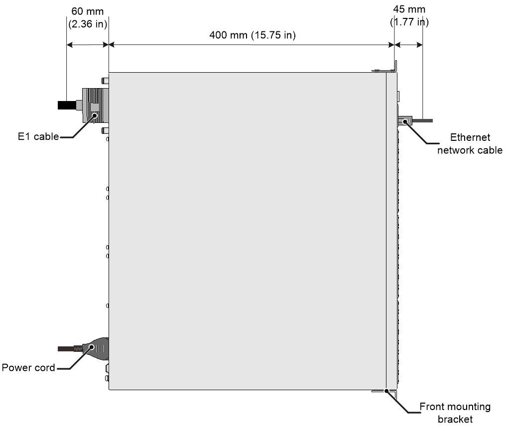
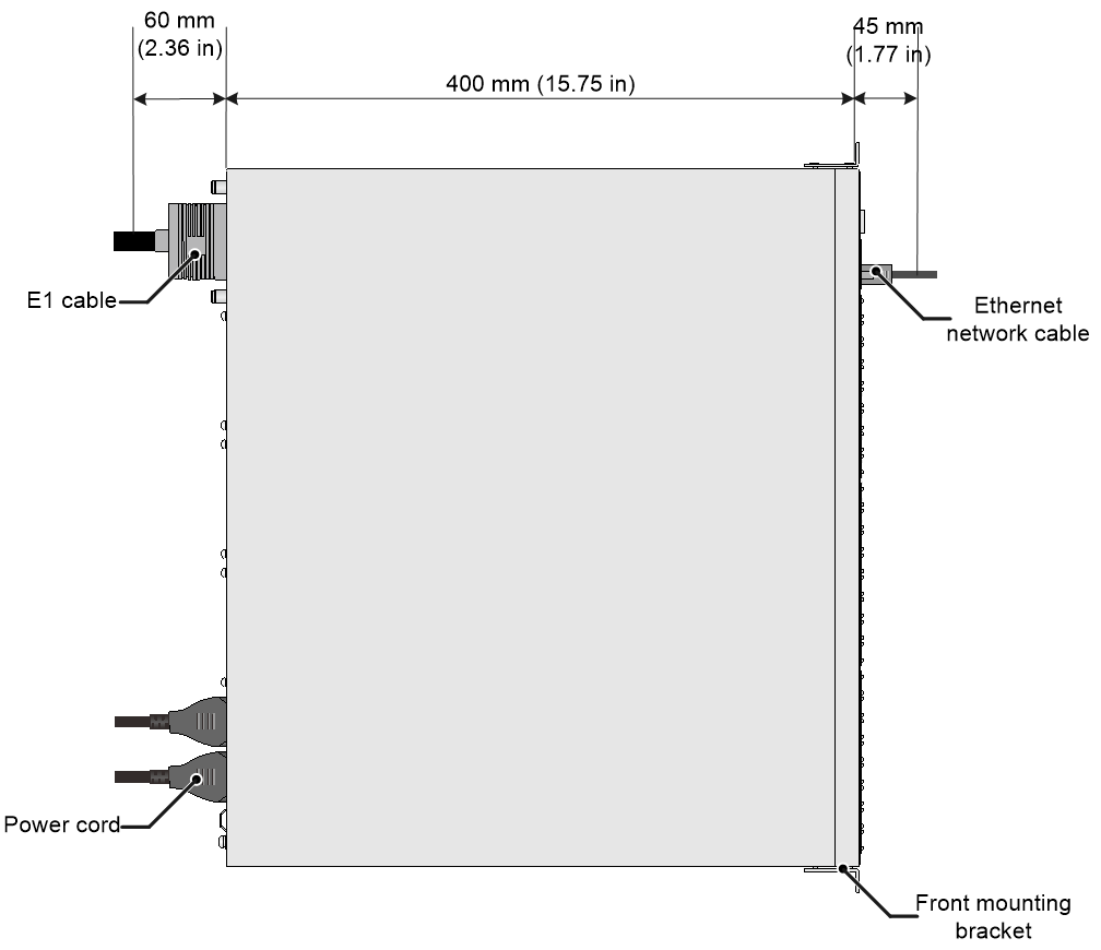
Figure2-18 MSR3600-51-X1-DP/MSR3600-28-G-DP/MSR3600-51-G-DP router dimensions
To house the router, the rack must meet the requirements described in Table2-1.
Table2-1 Router dimensions and requirements for the rack
|
Router model |
Dimensions |
Requirements for the rack |
|
MSR 36-10 |
· Height—44.2 mm (1.74 in), 1 RU · Width—440 mm (17.32 in) · Total depth—605 mm (23.82 in) ¡ Chassis depth—480 mm (18.90 in) ¡ Space for connecting an RPS power cord—65 mm (2.56 in) ¡ Space for connecting an E1 cable—60 mm (2.36 in) |
· Depth—A minimum of 800 mm (31.50 in) · Distance from the front post to the front door—A minimum of 80 mm (3.15 in) · Distance from the front post to the rear door—A minimum of 550 mm (21.65 in) · Distance from the front post to the rear post ¡ 290 mm (11.42 in)
to 430 mm (16.93 in) ¡ 450 mm (17.72 in) to 610 mm (24.02 in) |
|
MSR 36-20 |
· Height—44.2 mm (1.74 in), 1 RU · Width—440 mm (17.32 in) · Total depth—605 mm (23.82 in) ¡ Chassis depth—480 mm (18.90 in) ¡ Space for connecting an RPS power cord—65 mm (2.56 in) ¡ Space for connecting an E1 cable—60 mm (2.36 in) |
· Depth—A minimum of 800 mm (31.50 in) · Distance from the front post to the front door—A minimum of 80 mm (3.15 in) · Distance from the front post to the rear door—A minimum of 550 mm (21.65 in) · Distance from the front post to the rear post ¡ 290 mm (11.42 in) to 430 mm (16.93 in) ¡ 450 mm (17.72 in) to 610 mm (24.02 in) |
|
MSR3610-G MSR3620-G |
· Height—44.2 mm (1.74 in), 1 RU · Width—440 mm (17.32 in) · Total depth—575 mm (22.64 in) ¡ Chassis depth—470 mm (18.50 in) ¡ Space for connecting an E1 cable—60 mm (2.36 in) ¡ Space for connecting a power cord—45 mm (1.77 in) |
· Depth—A minimum of 800 mm (31.50 in) · Distance from the front post to the front door—A minimum of 80 mm (3.15 in) · Distance from the front post to the rear door—A minimum of 550 mm (21.65 in) |
|
MSR3620-X1 MSR3620-X1-XS MSR3620-DP MSR3620-XS |
· Height—44.2 mm (1.74 in), 1 RU · Width—440 mm (17.32 in) · Total depth—575 mm (22.64 in) ¡ Chassis depth—470 mm (18.50 in) ¡ Space for connecting an Ethernet cable—45 mm (1.77 in) ¡ Space for connecting an E1 cable—60 mm (2.36 in) |
· Depth—A minimum of 800 mm (31.50 in) · Distance from the front post to the front door—A minimum of 70 mm (2.76 in) · Distance from the front post to the rear door—A minimum of 500 mm (19.69 in) · Distance from the front post to the rear post—286 to 608 mm (11.26 to 23.94 in) |
|
MSR 36-40 MSR3640-G MSR3640-X1 MSR3640-XS MSR3640-X1-H1 MSR3660-XS |
· Height—88.1 mm (3.47 in), 2 RU · Width—440 mm (17.32 in) · Total depth—600 mm (23.62 in) ¡ Chassis depth—480 mm (18.90 in) ¡ Space for connecting an E1 cable—60 mm (2.36 in) ¡ Space for connecting a power cord—60 mm (2.36 in) |
· Depth—A minimum of 800 mm (31.50 in) · Distance from the front post to the front door—A minimum of 80 mm (3.15 in) · Distance from the front post to the rear door—A minimum of 550 mm (21.65 in) · Distance from the front post to the rear post ¡ 310 mm (12.20 in) to 440 mm (17.32 in) ¡ 465 mm (18.31 in) to 595 mm (23.43 in) (As a best practice, use a rack shelf to mount the router in a rack.) |
|
MSR 36-60 |
· Height—135 mm (5.32 in), 3 RU · Width—440 mm (17.32 in) · Total depth—600 mm (23.62 in) ¡ Chassis depth—480 mm (18.90 in) ¡ Space for connecting an E1 cable—60 mm (2.36 in) ¡ Space for connecting a power cord—60 mm (2.36 in) |
· Depth—A minimum of 800 mm (31.50 in) · Distance from the front post to the front door—A minimum of 80 mm (3.15 in) · Distance from the front post to the rear door—A minimum of 550 mm (21.65 in) · Distance from the front post to the rear post ¡ 310 mm (12.20 in) to 440 mm (17.32 in) ¡ 465 mm (18.31 in) to 595 mm (23.43 in) (As a best practice, use a rack shelf to mount the router in a rack.) |
|
MSR3600-28 |
· Height—44.2 mm (1.74 in), 1 RU · Width—440 mm (17.32 in) · Total depth—480 mm (18.90 in) ¡ Chassis depth—360 mm (14.17 in) ¡ Space for connecting an AC power cord—60 mm (2.36 in) ¡ Space for connecting an E1 cable—60 mm (2.36 in) |
· Depth—A minimum of 600 mm (23.62 in) · Distance from the front post to the front door—A minimum of 80 mm (3.15 in) · Distance from the front post to the rear door—A minimum of 420 mm (16.54 in) |
|
MSR3610-X1 MSR3610-XS MSR3610-X1-DP MSR3610-X1-DC MSR3610-X1-DP-DC |
· Height—43.6 mm (1.72 in), 1 RU · Width—440 mm (17.32 in) · Depth—480 mm (18.90 in) ¡ 360 mm (14.17 in) for the chassis ¡ 60 mm (2.36 in) for connecting AC or DC power cord at the front ¡ 60 mm (2.36 in) for connecting the E1 cable at the rear |
· A minimum of 600 mm (1.97 ft) in depth (recommended) · A minimum of 80 mm (3.15 in) between the front rack post and the front door. · A minimum of 420 mm (16.54 in) between the front rack post and the rear door. |
|
MSR3610E-X1 MSR3610E-X1-DP |
· Height—44.2 mm (1.74 in), 1 RU · Width—440 mm (17.32 in). · Depth—440 mm (17.32 in). ¡ 320 mm (12.60 in) for the chassis. ¡ 60 mm (2.36 in) for connecting AC power cords at the front. ¡ 60 mm (2.36 in) for connecting the E1 cable at the rear. |
· A minimum of 600 mm (23.62 in) in depth (recommended). · A minimum of 80 mm (3.15 in) between the front rack post and the front door. · A minimum of 550 mm (21.65 in) between the front rack post and the rear door. |
|
MSR3600-28-SI |
· Height—43.6 mm (1.72 in), 1 RU · Width—440 mm (17.32 in) · Total depth—465 mm (18.31 in) ¡ Chassis depth—360 mm (14.17 in) ¡ Space for connecting an AC power cord—60 mm (2.36 in) ¡ Space for connecting an Ethernet cable—45 mm (1.77 in) |
· Depth—A minimum of 600 mm (23.62 in) · Distance from the front post to the front door—A minimum of 80 mm (3.15 in) · Distance from the front post to the rear door—A minimum of 420 mm (16.54 in) |
|
MSR3600-28-X1 MSR3600-28-XS MSR3600-28-X1-DP |
· Height—43.6 mm (1.72 in), 1 RU · Width—440 mm (17.32 in) · Total depth—480 mm (18.90 in) ¡ Chassis depth—360 mm (14.17 in) ¡ Space for connecting an AC power cord—60 mm (2.36 in) · Space for connecting an Ethernet cable—60 mm (2.36 in) |
· Depth—A minimum of 600 mm (23.62 in) · Distance from the front post to the front door—A minimum of 80 mm (3.15 in) · Distance from the front post to the rear door—A minimum of 420 mm (16.54 in) |
|
MSR3600-51 |
· Height—44.2 mm (1.74 in), 1 RU · Width—440 mm (17.32 in) · Total depth—505 mm (19.88 in) ¡ Chassis depth—400 mm (15.75 in) ¡ Space for connecting an Ethernet cable—45 mm (1.77 in) ¡ Space for connecting an E1 cable—60 mm (2.36 in) |
· Depth—A minimum of 600 mm (23.62 in) · Distance from the front post to the front door—A minimum of 80 mm (3.15 in) · Distance from the front post to the rear door—A minimum of 460 mm (18.11 in) |
|
MSR3600-51-SI |
· Height—43.6 mm (1.72 in), 1 RU · Width—440 mm (17.32 in) · Total depth—465 mm (18.31 in) ¡ Chassis depth—360 mm (14.17 in) ¡ Space for connecting an Ethernet cable—45 mm (1.77 in) ¡ Space for connecting an AC power cord—60 mm (2.36 in) |
· Depth—A minimum of 600 mm (23.62 in) · Distance from the front post to the front door—A minimum of 80 mm (3.15 in) · Distance from the front post to the rear door—A minimum of 420 mm (16.54 in) |
|
MSR3600-51-X1 MSR3600-51-X1-DP MSR3600-28-G-DP MSR3600-51-G-DP |
· Height—43.6 mm (1.72 in), 1 RU · Width—440 mm (17.32 in) · Total depth—505 mm (19.88 in) ¡ Chassis depth—400 mm (15.75 in) ¡ Space for connecting an Ethernet cable—45 mm (1.77 in) · Space for connecting an E1 cable—60 mm (2.36 in) |
· Depth—A minimum of 600 mm (23.62 in) · Distance from the front post to the front door—A minimum of 80 mm (3.15 in) · Distance from the front post to the rear door—A minimum of 460 mm (18.11 in) |
Rack-mounting methods
The MSR3600-28-SI-GL router supports rack-mounting by using front mounting brackets or using front mounting brackets and slide rails.
The following routers support rack-mounting by using front mounting brackets:
· MSR3610-X1
· MSR3610-XS
· MSR3610-X1-DP
· MSR3610-X1-DC
· MSR3610-X1-DP-DC
· MSR3610E-X1
· MSR3610E-X1-DP
· MSR3600-28
· MSR3600-51
· MSR3600-28-SI
· MSR3600-51-SI
· MSR3600-28-X1
· MSR3600-28-XS
· MSR3600-51-X1
· MSR3600-28-X1-DP
· MSR3600-51-X1-DP
The following routers support rack-mounting by using front and rear mounting brackets:
· MSR 36-10
· MSR 36-20
· MSR3610-G
· MSR3620-G
· MSR3620-X1
· MSR3620-X1-XS
· MSR3620-DP
· MSR3620-XS
· MSR 36-40
· MSR 36-60
· MSR3640-G
· MSR3640-X1
· MSR3640-XS
· MSR3640-X1-HI
· MSR3660-XS
· MSR3600-28-G-DP
· MSR3600-51-G-DP
Table2-2 Rack-mounting methods
|
Rack-mounting method |
Installation accessories |
Installation procedure |
|
Rack-mounting the router with front mounting brackets |
· Front mounting brackets · M4 mounting bracket screws · M6 rack screws (user supplied) · Cage nuts (user supplied) |
See "Rack-mounting the router by using front mounting brackets." |
|
Rack-mounting with front and rear mounting brackets |
· Front mounting brackets · Rear mounting brackets · M4 mounting bracket screws · M6 rack screws (user supplied) · Cage nuts (user supplied) |
See "Rack-mounting the router by using front and rear mounting brackets." |
|
Rack-mounting the router with front mounting brackets and slide rails |
· Front mounting brackets · Slide rails · M4 mounting bracket screws · M6 rack screws (user supplied) · Cage nuts (user supplied) |
See "Rack-mounting the router by using front mounting brackets and slide rails." |
|
|
CAUTION: The mounting brackets can support only the weight of the router itself. To avoid damages, do not add additional load to the router. |
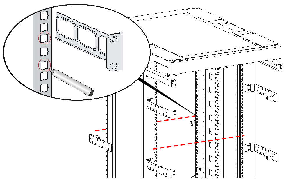
Rack-mounting the router by using front mounting brackets
1. Use a front mounting bracket to mark the positions of cage nuts on the front rack posts, making sure they are at the same level.
Figure2-19 Marking the positions of cage nuts on the front rack posts
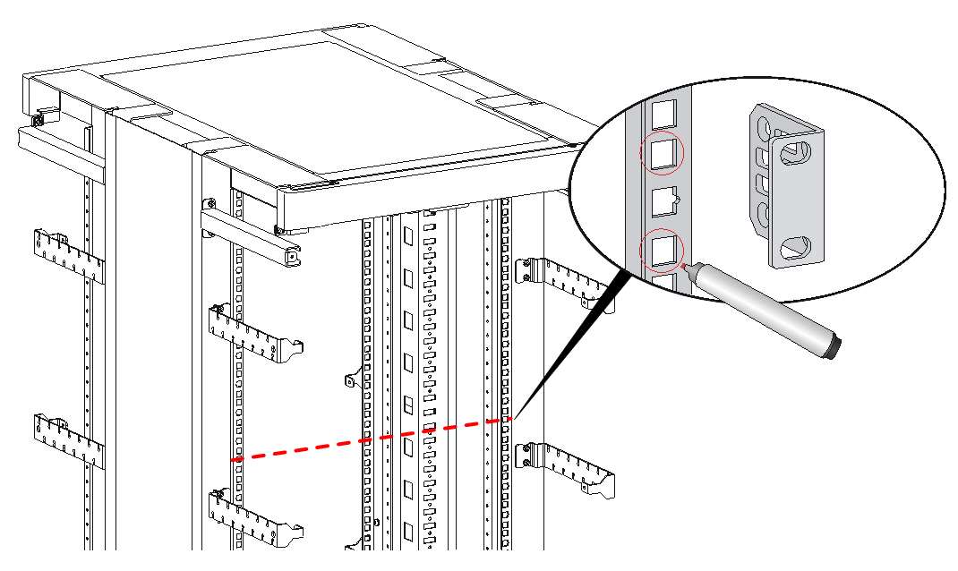
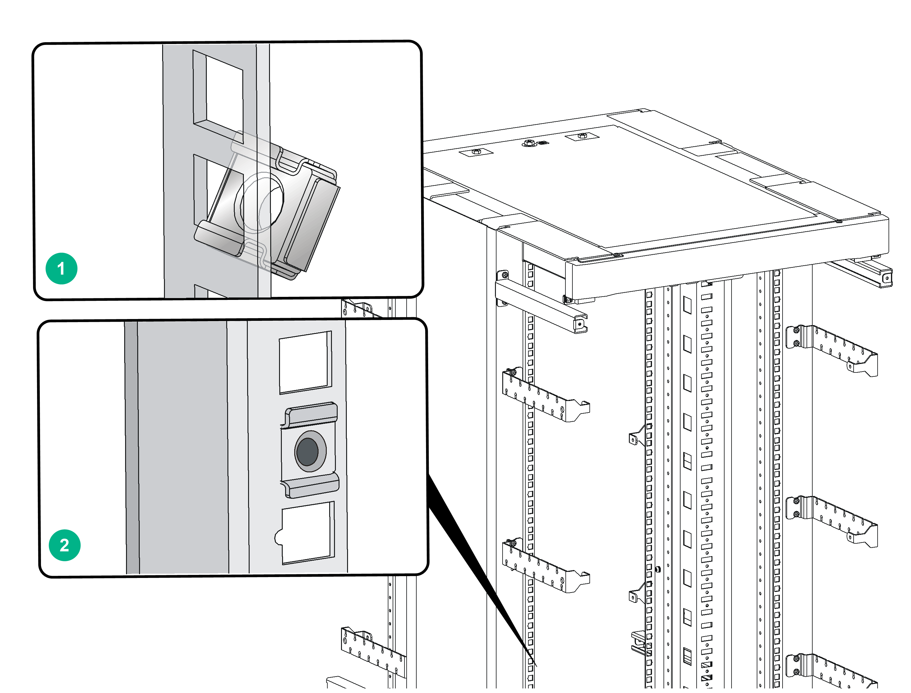
2. Insert one edge of a cage nut into the square hole on a rack post. Use a flat-blade screwdriver to compress the other edge of the cage nut, and then push the cage nut fully into the hole.
3. Repeat step 2 to install other cage nuts to all the marked positions on the rack posts.
Figure2-20 Installing cage nuts
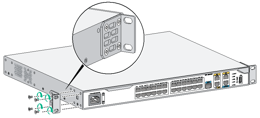
4. Attach the front mounting brackets to the chassis and fasten the screws.
Figure2-21 Attaching the front mounting brackets to the chassis
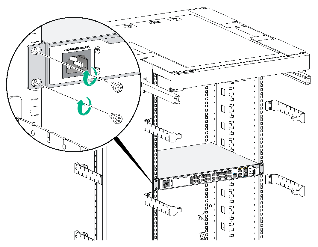
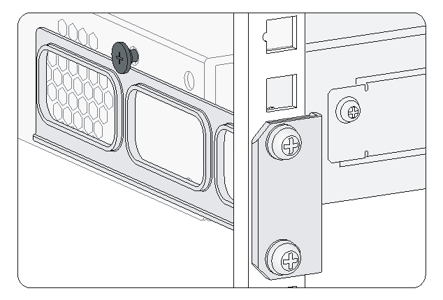
5. Place the router on the rack, and secure the chassis in the rack by attaching the front mounting brackets with pan head screws onto the back.
Figure2-22 Installing the router in the rack
Rack-mounting the router by using front and rear mounting brackets
1. Use a front mounting bracket to mark the positions of cage nuts on the front rack posts, making sure they are at the same level.
Figure2-23 Marking the positions of cage nuts for the front mounting brackets
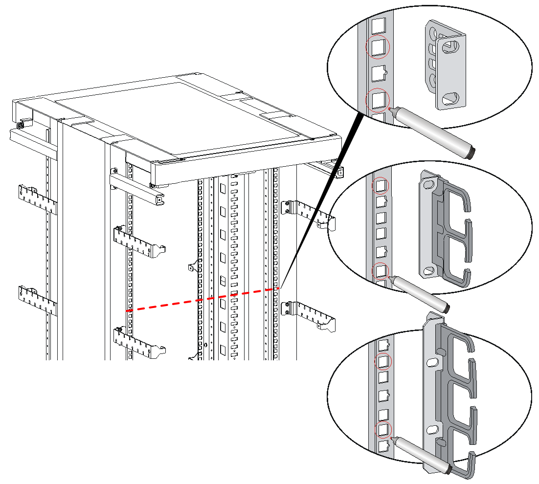
2. Use a rear mounting bracket to mark the positions of cage nuts on the rear rack posts, making sure the front and rear mounting brackets are at the same level.
Figure2-24 Marking the positions of cage nuts for the rear mounting brackets
3. Insert one edge of a cage nut into the square hole on a rack post. Use a flat-blade screwdriver to compress the other edge of the cage nut, and then push the cage nut fully into the hole.
4. Repeat step 3 to install other cage nuts to all the marked positions on the rack posts.
Figure2-25 Installing cage nuts

5. Attach the rear mounting brackets to the rack and fasten the screws.
The depth of the router might be greater or smaller than the depth of the rack, depending on the rack model. If the depth of the router is greater than the depth of the rack, follow Figure2-26 to attach the rear mounting brackets. If smaller, follow Figure2-27 to attach the rear mounting brackets.
Figure2-26 Attaching the rear mounting brackets (router depth greater than rack depth)
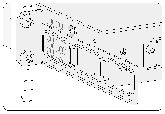
Figure2-27 Attaching the rear mounting brackets (router depth smaller than rack depth)
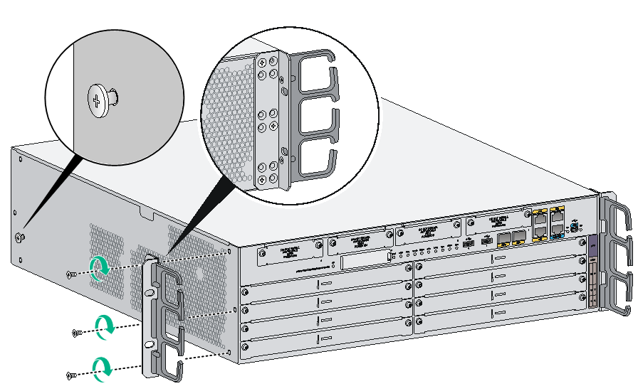
6. Attach the front mounting brackets to the chassis and fasten the screws.
7. Attach shoulder screws to the rear of the chassis.
Figure2-28 Attaching the front mounting brackets and shoulder screws to the MSR 36-10/MSR 36-20/MSR3610-G/MSR3620-G/MSR3620-X1/MSR3620-X1-XS/MSR3620-DP/MSR3620-XS/MSR3600-28-G-DP/MSR3600-51-G-DP router
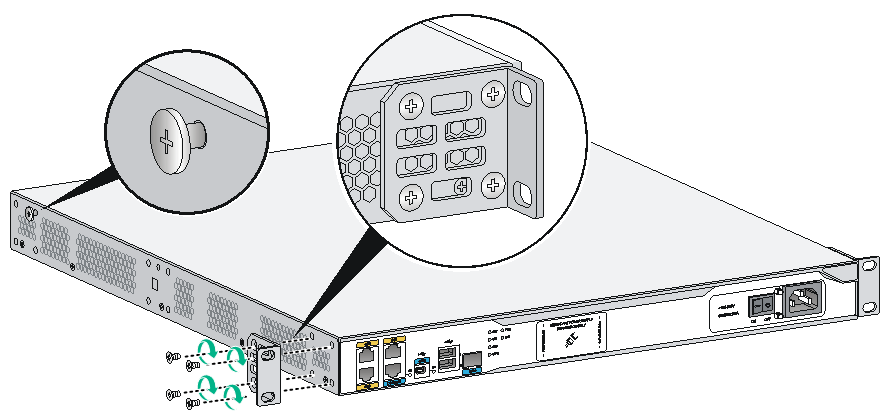
Figure2-29 Attaching the front mounting brackets and shoulder screws to the MSR 36-40/MSR3640-G/MSR3640-X1/MSR3640-XS/MSR3640-X1-HI/MSR3660-XS router
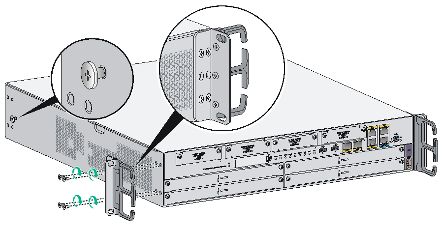
Figure2-30 Attaching the front mounting brackets and shoulder screws to the MSR 36-60 router
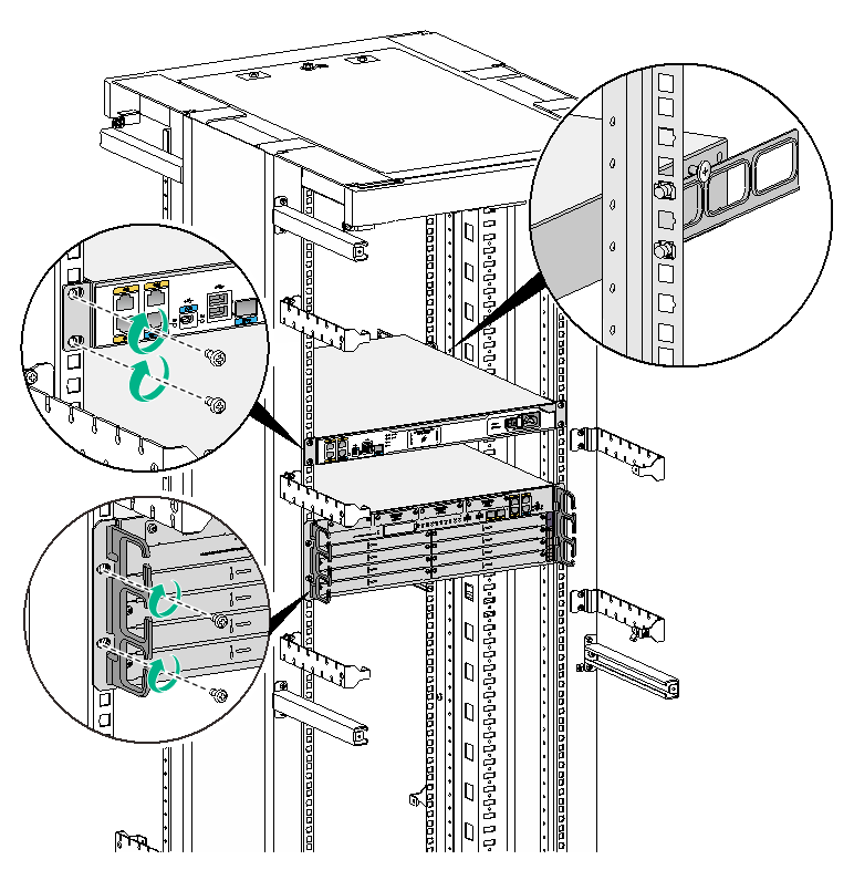
8. Place the router on the rack, making sure the shoulder screws hang on the rear mounting brackets. Secure the chassis in the rack by attaching the front mounting brackets with pan head screws onto the back.
Figure2-31 Mounting the router in the rack
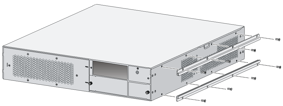
Rack-mounting the router by using front mounting brackets and slide rails
No slide rails are provided with the router. Prepare them yourself as required.
To rack-mount the router by using front mounting brackets and slide rails.
1. Attach slide rails to the rack. As a best practice, use H3C slide rails for the router. Table2-3 describes the H3C slide rails recommended for the router. For the slide rail installation method, see H3C LSXM1BSR 1U Bottom-Support Rails Installation Guide.
|
Slide rail model |
Adjustable range |
Occupied rack space |
|
LSXM1BSR |
630 to 900 mm (24.80 to 35.43 in) |
1 RU |
2. Attach mounting brackets to the router. For the attachment method, see "Rack-mounting the router by using front mounting brackets."
3. Install the router in the rack.
a. Orient the router for the rear of the router to face the front of the rack.
b. Hold the router at two sides and lift it until the bottom of the router is slightly above the slide rails on the rack. Place the router on the slide rails from the front of the rack.
c. Slide the router smoothly into the rack until the router mounting brackets are flush against the rack.
d. Use the M6 rack screws to secure the router mounting brackets to the rack.
Figure2-32 Installing the router in a rack
Grounding the router
|
|
WARNING! Correctly connecting the router grounding cable is crucial to lightning protection and EMI protection. |
|
|
IMPORTANT: The resistance reading must be smaller than 5 ohms between the chassis and the ground. |
Grounding the router through the grounding terminal on the rack
|
|
IMPORTANT: Make sure the rack is correctly grounded before grounding the router. |
To connect the grounding cable:
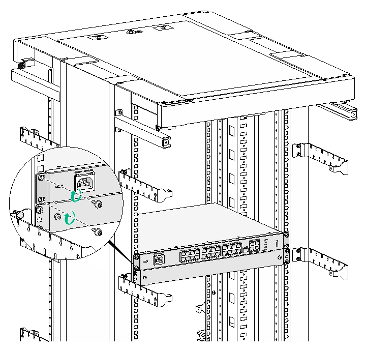
1. Remove the grounding screw from the grounding hole on the rear panel of the chassis.
2. Use the grounding screw to attach the ring terminal of the grounding cable to the chassis. See Figure2-33.
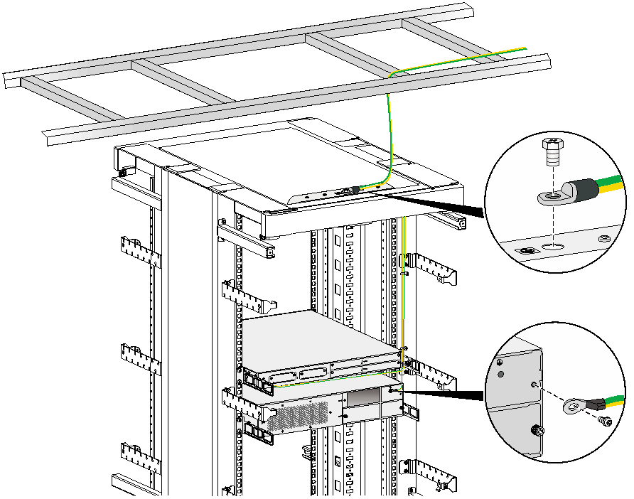
3. Remove the hex nut on the grounding post of the grounding strip on the rack.
4. Use needle-nose pliers to bend a hook at the other end of the grounding cable, attach it to the grounding post, and secure it with the hex nut. See Figure2-34.
Figure2-33 Connecting the grounding cable to the router
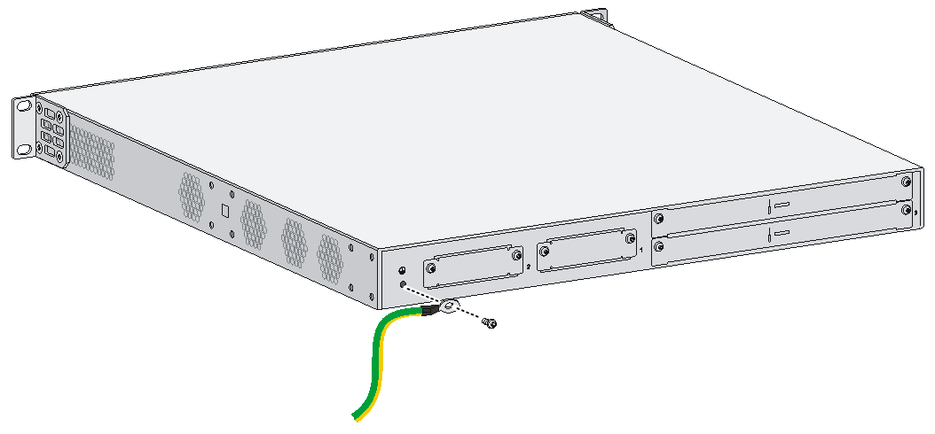
Figure2-34 Grounding the router through the grounding terminal on the rack
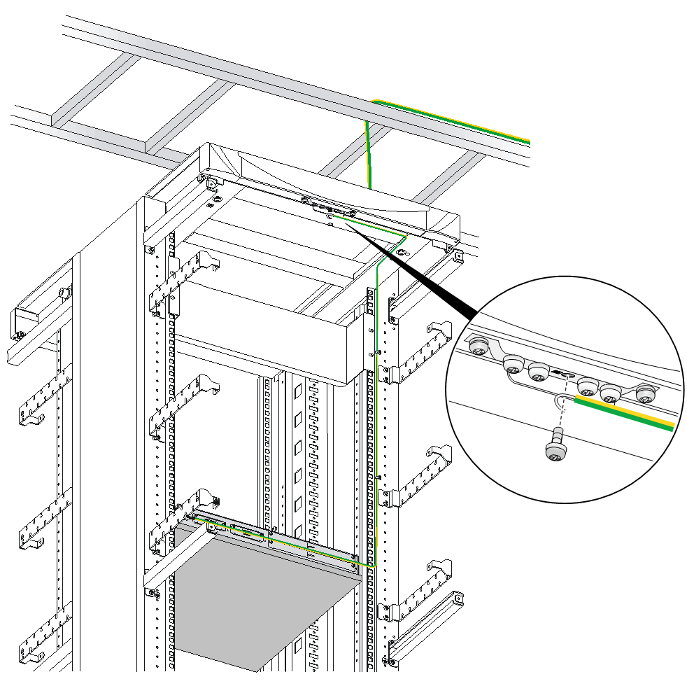
Grounding the router with a grounding strip
If a grounding strip is available at the installation site, connect the grounding cable to the grounding strip.
Follow the same procedures in "Grounding the router through the grounding terminal on the rack" to connect the grounding cable.
Figure2-35 Grounding the router with a grounding strip
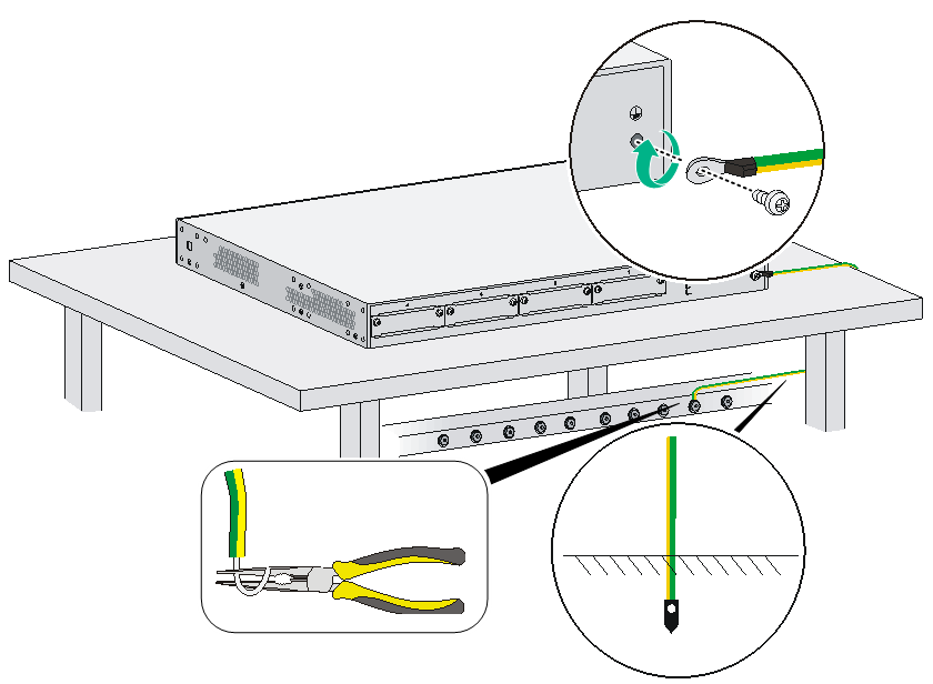
Grounding the router with a grounding conductor buried in the earth ground
If the installation site has no grounding strips, but earth ground is available, hammer a 0.5 m (1.64 ft) or longer angle iron or steel tube into the earth ground to serve as a grounding conductor. The steel tube must be zinc-coated. Weld the yellow-green grounding cable to the angel iron or steel tube and treat the joint for corrosion protection.
Installing an interface module
|
|
CAUTION: Cross-slot Layer 2 communication is not supported between any two SIC Ethernet switching modules and between a SIC Ethernet switching module and an HMIM Ethernet switching module. |
Installing a SIC
|
|
CAUTION: Only SIC modules with remove buttons are hot swappable. To avoid unexpected reboots of the device and unavailability of the interface modules, make sure the router is powered off before installing other SIC modules that are not hot swappable. |
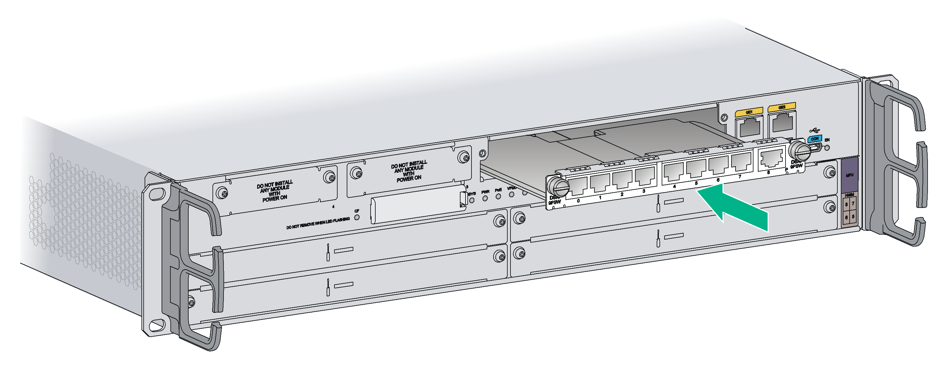
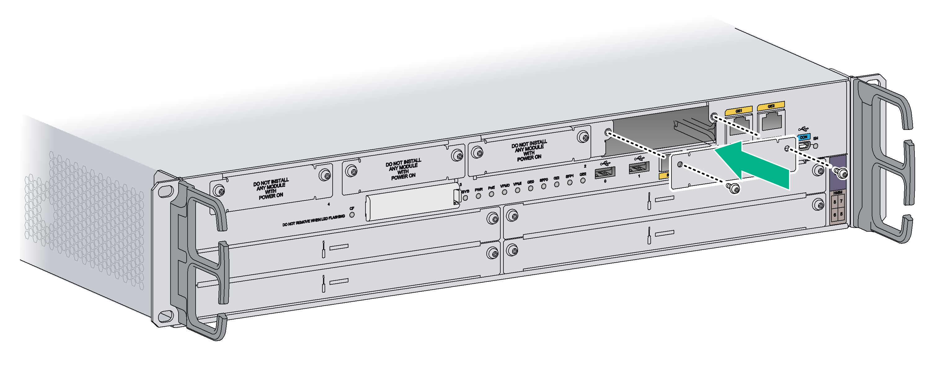
To install a SIC:
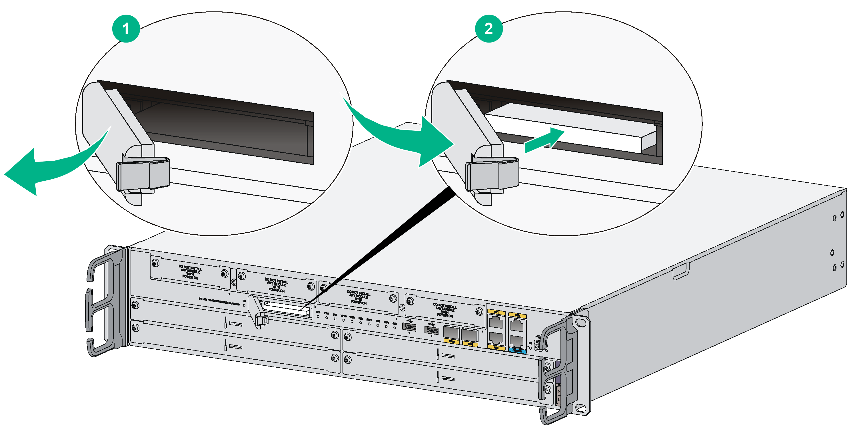
1. Remove the fastening screws with a Phillips screwdriver to remove the filler panel.
Keep the removed filler panel for future use.
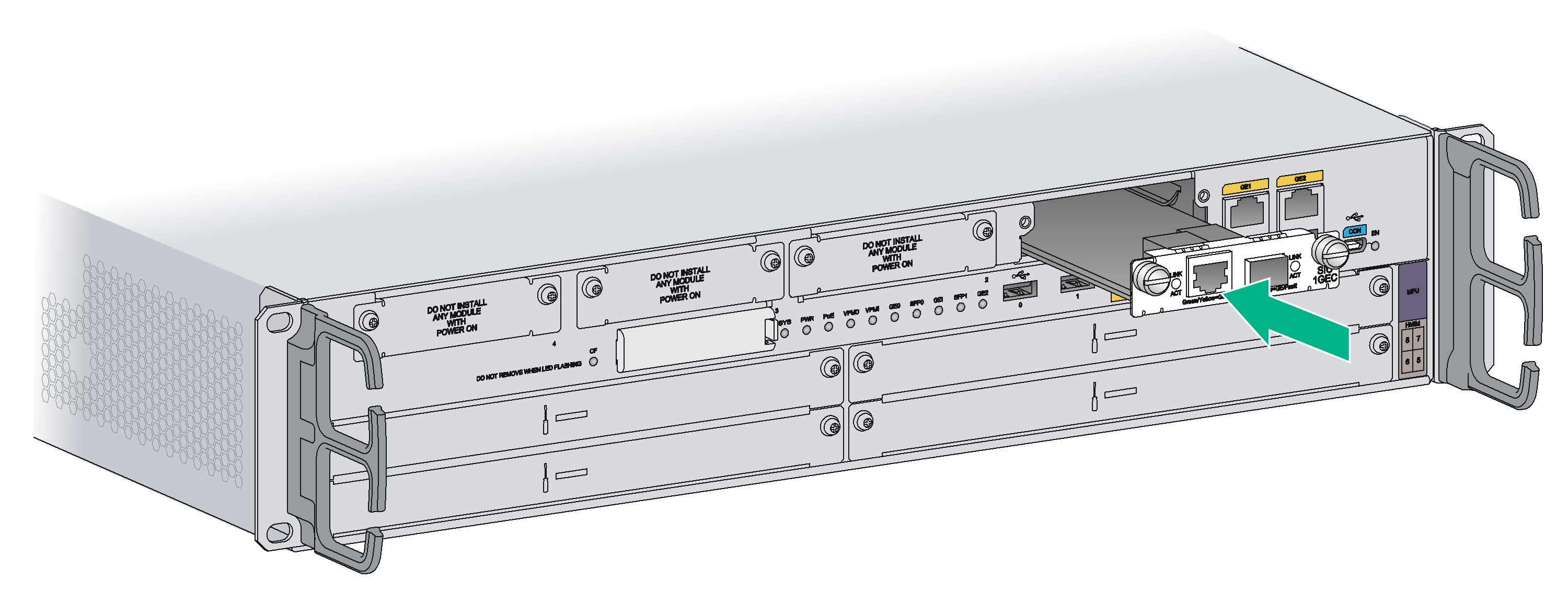
2. Push the SIC slowly along the slide rails into the slot until it makes close contact with the backplane of the router.
3. Use a Phillips screwdriver to fasten the captive screws on the SIC.
Figure2-36 Removing the filler panel
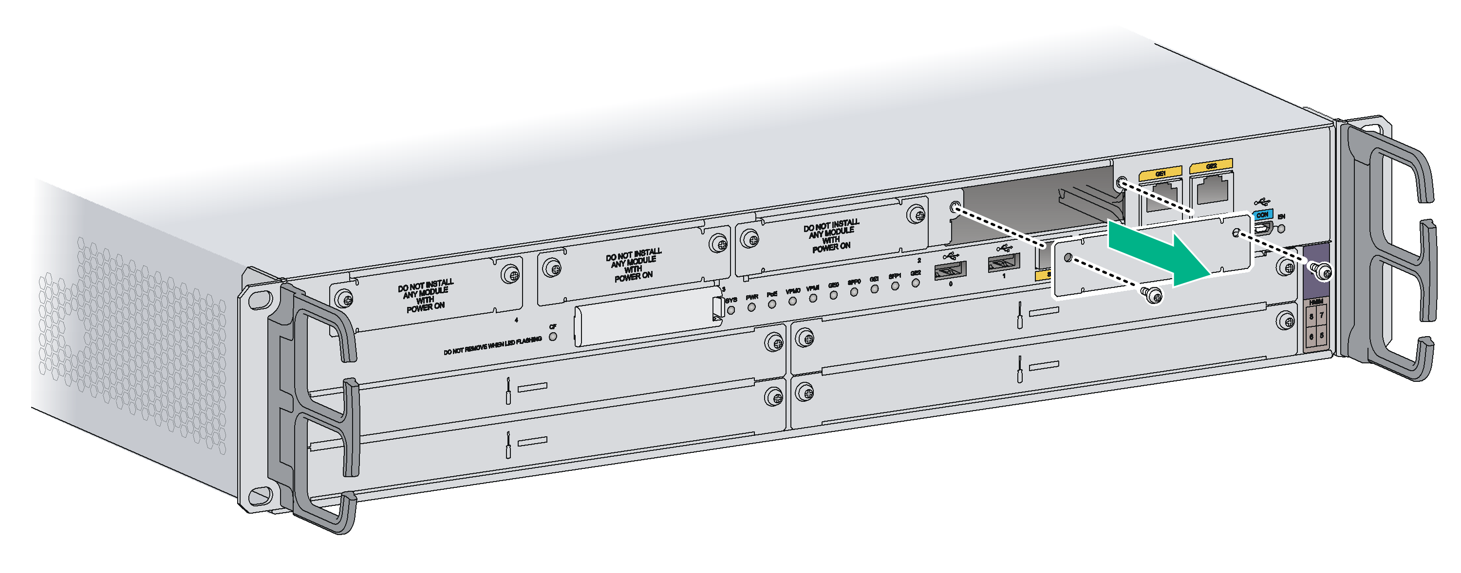
Figure2-37 Installing the SIC
Installing a DSIC
|
|
CAUTION: DSICs are not hot swappable. Make sure the router is powered off before installing a DSIC. |
Only the MSR 36-20/MSR 36-40/MSR 36-60 router supports DSICs. You must remove the slot divider between slot 1 and slot 2 or between slot 3 and slot 4 before you install a DSIC.
To install a DSIC:
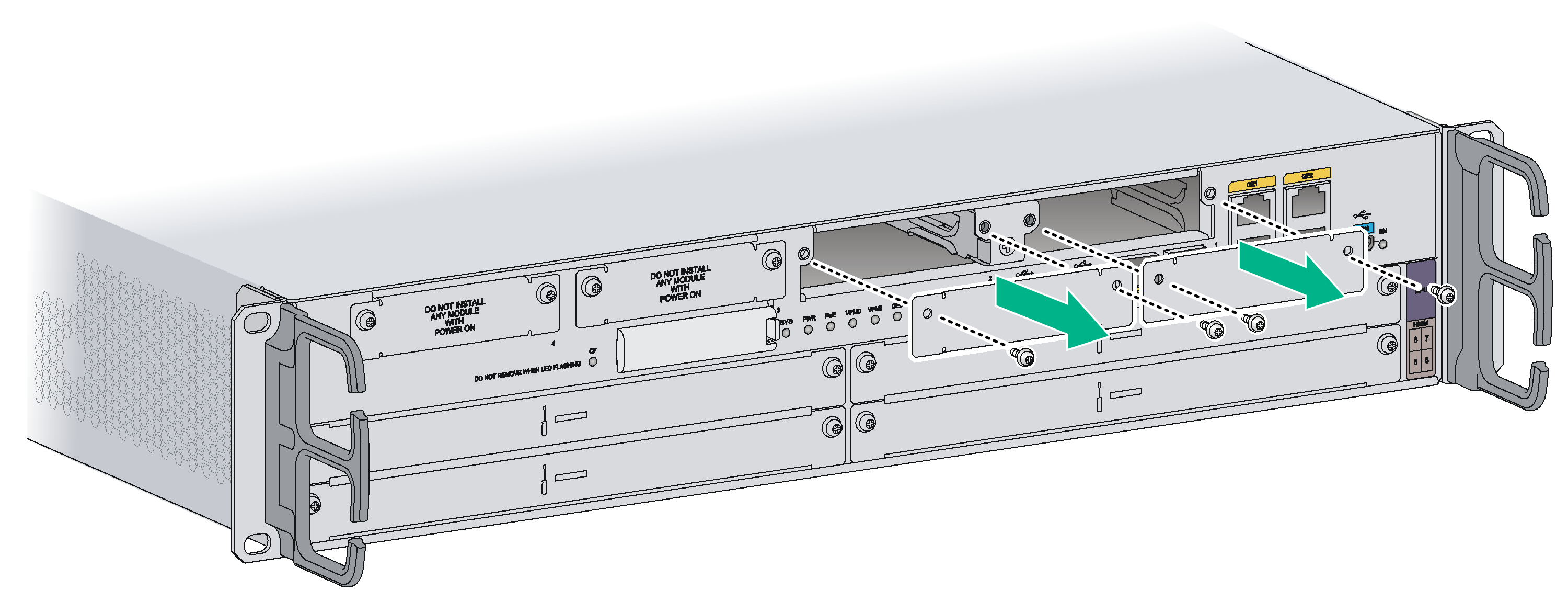
1. Remove the screws on the filler panels in SIC slots 1 and 2, or slots 3 and 4 of an MSR 36-20, MSR 36-40, or MSR 36-60 to remove the filler panel.
Figure2-38 Removing the filler panel
2. Loosen the captive screws on the slot divider and pull out the slot divider.
Figure2-39 Removing the slot divider
3. Insert the DSIC into the slot and push it along the slide rails until it makes close contact with the backplane of the router.
Figure2-40 Installing a DSIC
4. Fasten the captive screws to secure the DSIC.
Installing an HMIM
|
|
IMPORTANT: · You can install an HMIM when the router is operating. To hot-remove an HMIM, you must first execute the remove command or press the remove button on the HMIM. · If you install HMIMs on both of the HMIM slots on an MSR 36-20, when you insert an HMIM to the upper slot, slightly press down the HMIM, and then push it into the slot. · To install a 0.5 U HMIM into HMIM slot 3 on an MSR 36-10 or HMIM slot 9 or 10 on an MSR 36-60, install the HMIM in the lower part of the slot. Make sure the HMIM has good contact with the connectors in the slot. |
The following routers do not support HMIMs:
· MSR3610-X1
· MSR3610-XS
· MSR3610-X1-DP
· MSR3610-X1-DC
· MSR3610-X1-DP-DC
· MSR3610E-X1
· MSR3610E-X1-DP
· MSR3600-28
· MSR3600-28-SI
· MSR3600-28-SI-GL
· MSR3600-28-X1
· MSR3600-28-X1-DP
· MSR3600-28-XS
· MSR3600-51
· MSR3600-51-SI
· MSR3600-51-X1
· MSR3600-51-X1-DP
· MSR3600-28-G-DP
· MSR3600-51-G-DP
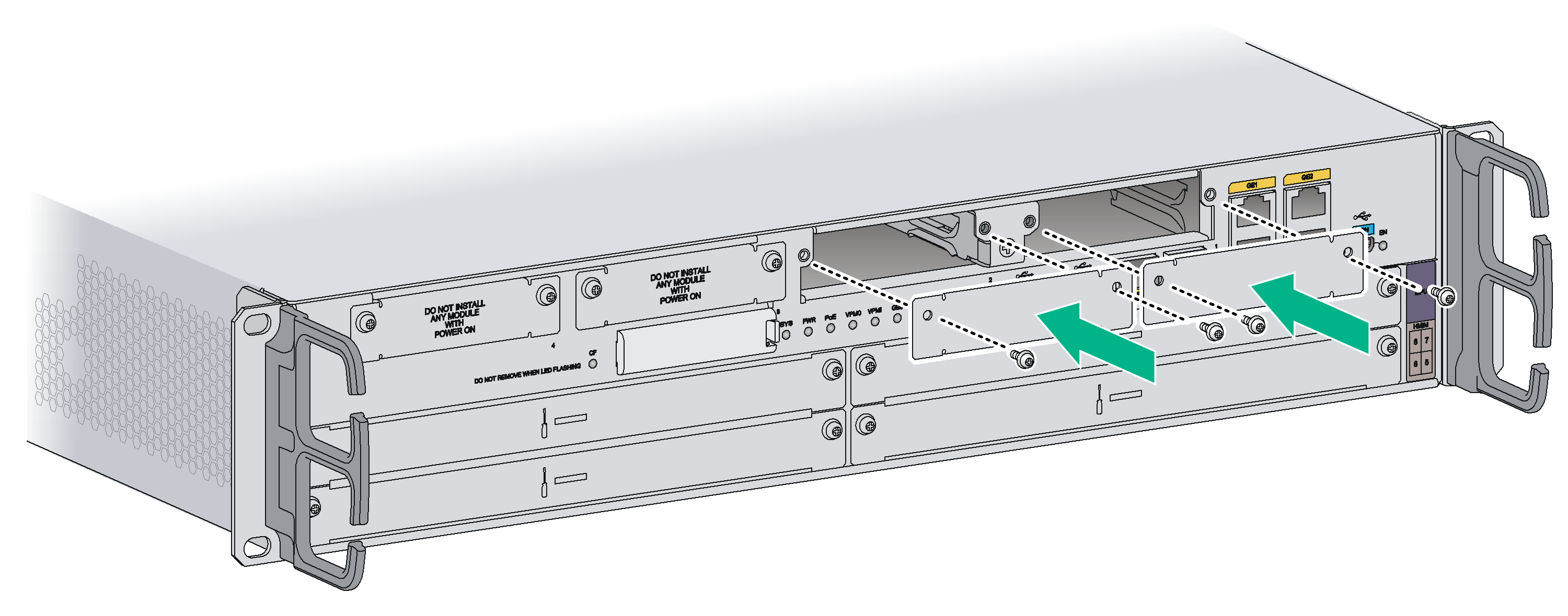
An HMIM can be 1 U or 0.5 U. When you install a 1U HMIM to an MSR router, remove the filler panels of the target slot and the neighboring slot above. This section uses a 0.5 U HMIM as an example.
To install an HMIM:
1. Remove the fastening screws with a Phillips screwdriver to remove the filler panel.
Keep the removed filler panel for future use.
Figure2-41 Removing the filler panel
2. Push the HMIM slowly along the slide rails into the slot until it makes close contact with the backplane of the router.
Figure2-42 Installing an HMIM
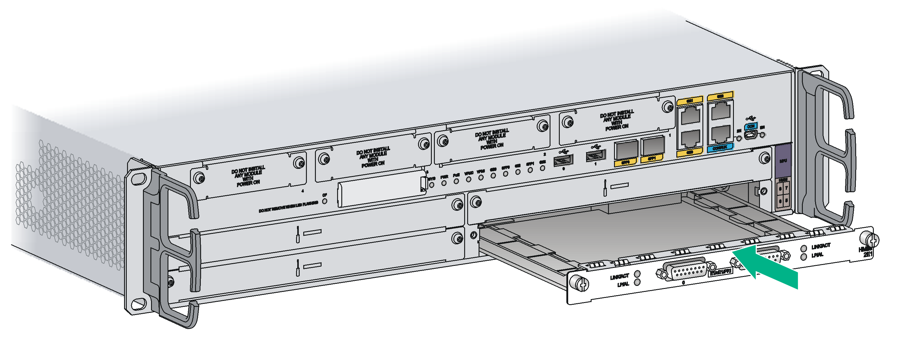
3. Fasten the captive screws on the HMIM to secure it to the router.
Installing a MIM
|
|
IMPORTANT: · To install a MIM, install it to the HMIM adapter and then insert it into the HMIM slot. · You can install a MIM when the router is operating. To hot-remove a MIM , you must first execute the remove command. · If you install MIMs on both of the HMIM slots on an MSR 36-20, when you insert a MIM to the upper slot, slightly press down the MIM, and then push it into the slot. · To install a 0.5 U MIM into HMIM slot 3 on an MSR 36-10 or HMIM slot 9 or 10 on an MSR 36-60, install the MIM in the lower part of the slot. Make sure the MIM has good contact with the connectors in the slot. |
The following routers do not support MIMs:
· MSR3610-X1
· MSR3610-XS
· MSR3610-X1-DP
· MSR3610-X1-DC
· MSR3610-X1-DP-DC
· MSR3610E-X1
· MSR3610E-X1-DP
· MSR3620-X1
· MSR3620-X1-XS
· MSR3640-G
· MSR3640-X1
· MSR3640-XS
· MSR3640-X1-H1
· MSR3660-XS
· MSR3600-28
· MSR3600-28-SI
· MSR3600-28-SI-GL
· MSR3600-28-X1
· MSR3600-28-X1-DP
· MSR3600-28-XS
· MSR3600-51
· MSR3600-51-SI
· MSR3600-51-X1
· MSR3600-51-X1-DP
· MSR3610-G
· MSR3620-G
· MSR3600-28-G-DP
· MSR3600-51-G-DP
A MIM can be 1 U or 0.5 U. When you install a 1 U MIM to an MSR router, remove the filler panels of the target slot and the neighboring slot above, and use the 1 U HMIM adapter. This section uses a 0.5 U MIM as an example.
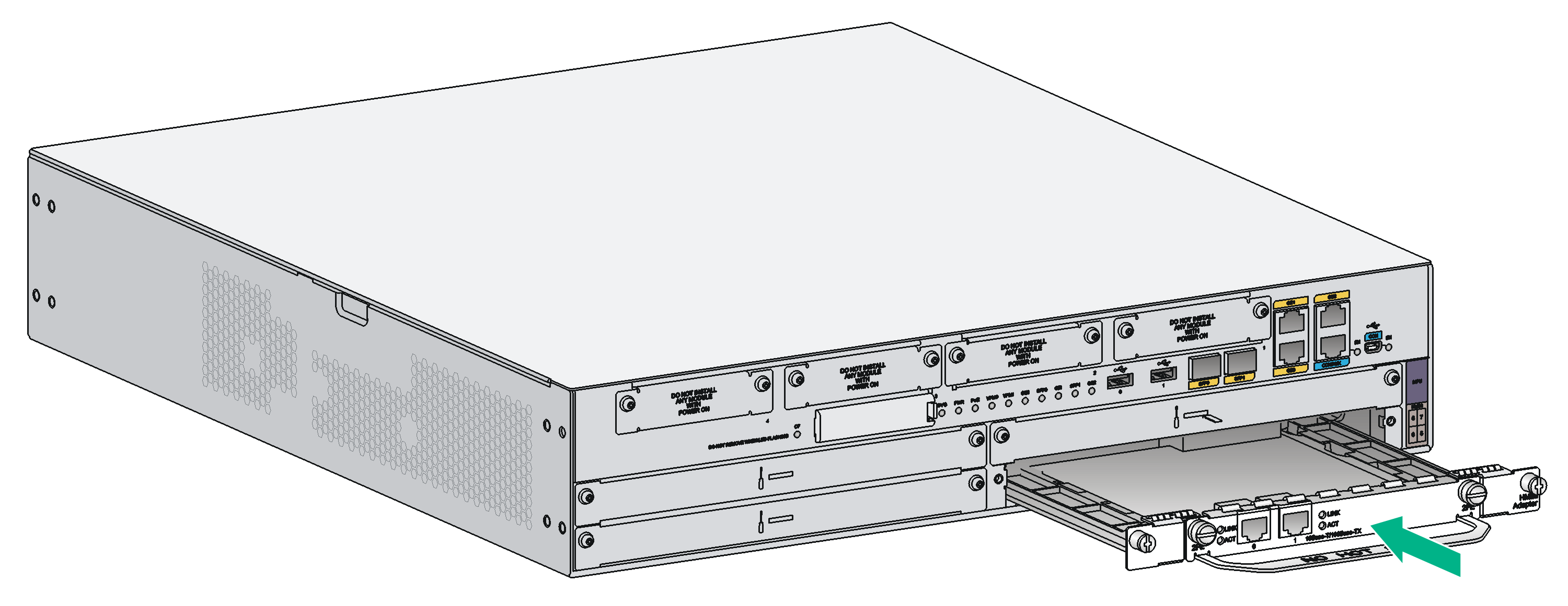
To install a MIM:
1. Remove the fastening screws on the filler panel in the HMIM slot with a Phillips screwdriver to remove the filler panel.
2. Push the MIM slowly along the slide rails of the HMIM adapter until it makes close contact with the backplane of the HMIM adapter.
3. Fasten the fastening screws.
4. Fasten the captive screws on the MIM to secure it to the HMIM adapter.
5. Push the MIM into the HMIM slot along the slide rails until it makes close contact with the backplane of the router.
6. Fasten the captive screws to secure the MIM to the router.
Figure2-43 Attaching a MIM to an HMIM adapter
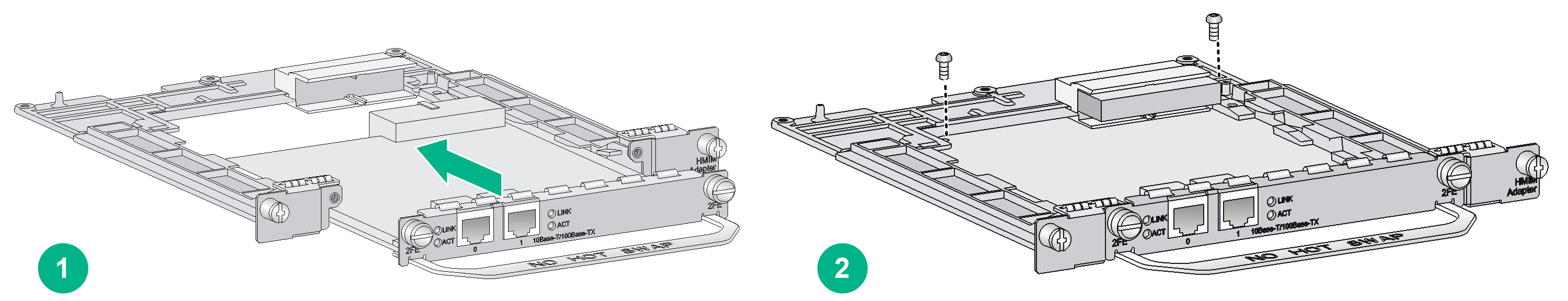
Figure2-44 Installing the MIM to the router
Connecting the router to the network
Connect the router to the network before powering on the router. This section describes how to connect the router to the network through Ethernet cables.
Connecting an Ethernet cable
1. Plug one end of an Ethernet twisted pair cable into the copper Ethernet port (RJ-45 port) on the router.
2. Plug the other end of the cable into the RJ-45 port of the peer device.
Figure2-45 Connecting the Ethernet cable
Connecting an optical fiber
|
|
WARNING! Do not stare into any fiber port when you connect an optical fiber. The laser light emitted from the optical fiber might hurt your eyes. |
The MSR3600-51 router does not support transceiver modules.
Follow these guidelines when you connect a fiber cable:
· Never bend or curve a fiber when connecting it.
· Make sure the Tx and Rx ends are correctly connected.
· Keep the fiber end clean.
· Be sure to install the dust cover if the fiber port is not connected to a fiber connector.
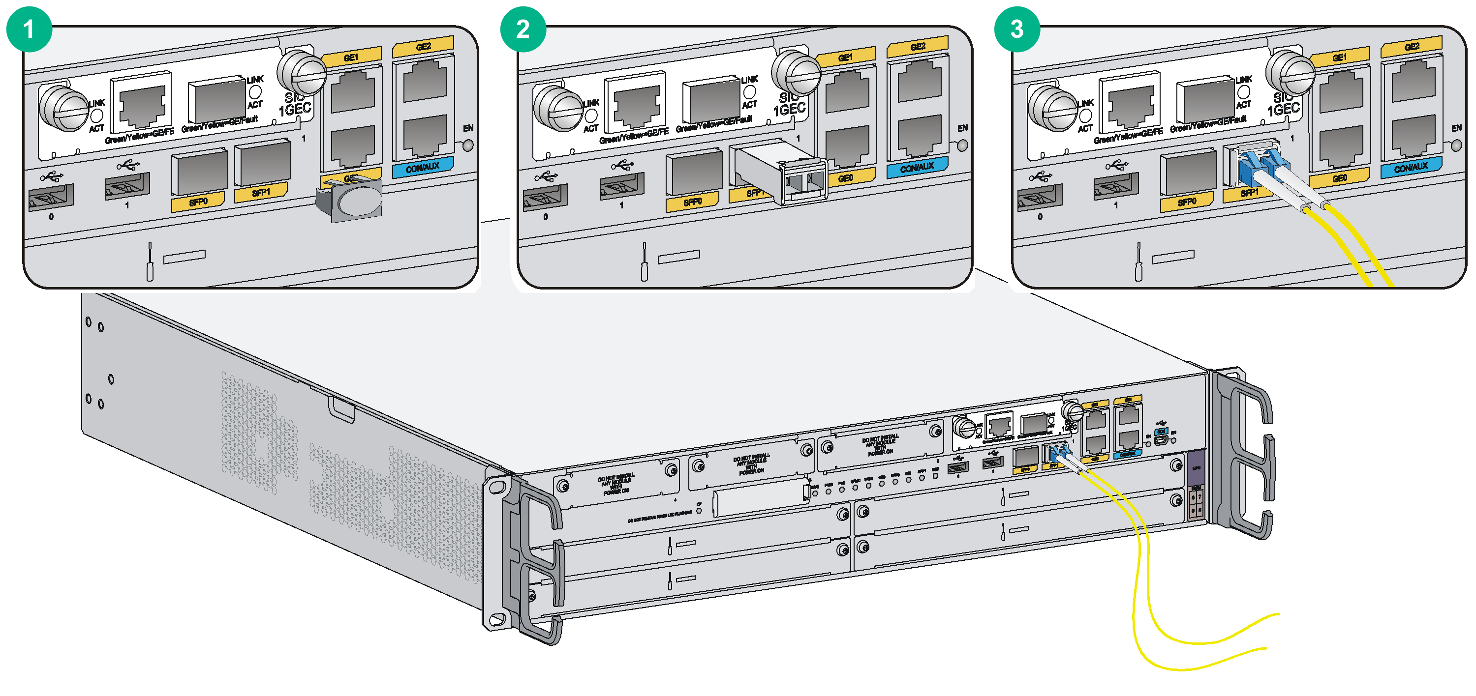
To connect an optical fiber:
1. Remove the dust plug from a fiber port of the router.
2. Remove the dust cover from the transceiver module, and plug the end without a pull latch into the fiber port.
3. Remove the dust cover from the fiber connector.
4. Identify the Rx and Tx ports. Plug the LC connector at one end of one fiber cable into the Rx port of the router and the LC connector at the other end into the Tx port of the peer device. Plug the LC connector at one end of another fiber cable into the Tx port of the router and the LC connector at the other end to the Rx port of the peer device.
5. Examine the Ethernet port LED after connection. For more information, see "LEDs" in hardware information and specifications.
Figure2-46 Connecting an optical fiber
Installing a CF card
The following routers do not support external CF cards:
· MSR 36-10
· MSR3610-G
· MSR3610-X1
· MSR3610-XS
· MSR3610-X1-DP
· MSR3610-X1-DC
· MSR3610-X1-DP-DC
· MSR3610E-X1
· MSR3610E-X1-DP
· MSR3620-G
· MSR3620-X1
· MSR3620-X1-XS
· MSR3620-DP
· MSR3620-XS
· MSR3640-G
· MSR3640-X1
· MSR3640-XS
· MSR3640-X1-H1
· MSR3660-XS
· MSR3600-28
· MSR3600-28-SI
· MSR3600-28-SI-GL
· MSR3600-28-X1
· MSR3600-28-X1-DP
· MSR3600-28-XS
· MSR3600-51
· MSR3600-51-SI
· MSR3600-51-X1
· MSR3600-51-X1-DP
· MSR3600-28-G-DP
· MSR3600-51-G-DP
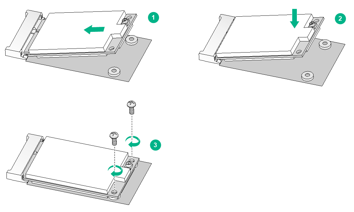
To install a CF card:
1. Open the CF card cover by pressing the spring clip.
2. Push the CF card eject button all the way into the slot, and make sure the button does not project from the panel.
3. Insert the CF card into the slot following the direction shown in Figure2-47, and make sure it does not project from the slot.
4. Close the CF card cover.
Figure2-47 Installing a CF card
Installing a Micro SD card
|
|
CAUTION: · To avoid startup failure of the router, do not replace the Micro SD card on an MSR3610-G or MSR3620-G router yourself. If the Micro SD card is damaged, please contact the local sales agent. · Micro SD cards on the MSR3610-G and MSR3620-G routers are not hot swappable. · Make sure a Micro SD card is installed with the metal pin side facing down. |
Micro SD cards are only supported on the following routers:
· MSR3610-G
· MSR3610-X1
· MSR3610-XS
· MSR3610-X1-DP
· MSR3610-X1-DC
· MSR3610-X1-DP-DC
· MSR3620-G
· MSR3620-DP
· MSR3620-XS.
For the following routers, you order Micro SD cards as required, because no Micro SD cards are provided with them:
· MSR3610-X1
· MSR3610-XS
· MSR3610-X1-DP
· MSR3610-X1-DC
· MSR3610-X1-DP-DC
· MSR3620-DP
· MSR3620-XS
Micro SD cards on the following routers are hot swappable:
· MSR3610-X1
· MSR3610-XS
· MSR3610-X1-DP
· MSR3610-X1-DC
· MSR3610-X1-DP-DC
· MSR3620-DP
· MSR3620-XS
To prevent Micro SD card damage and data loss, execute the umount command before you hot swap a Micro SD card.
To install a Micro SD card, push the Micro SD card slowly along the guide rails into the slot. To prevent card damage, do not use extra force.
Figure2-48 Installing the Micro SD card
Installing a SATA drive
Only the MSR3610-X1, MSR3610-XS, and MSR3610-X1-DP support a SATA drive. No SATA drive is provided with the device. To user a SATA drive, purchase one from H3C.
To install a SATA drive:
1. Remove the filler panel from the SATA drive slot, as shown in Figure2-49.
2. Push the SATA drive slowly into the slot along the guide rails, as shown in Figure2-50.
Figure2-49 Removing the filler panel from the SATA drive slot
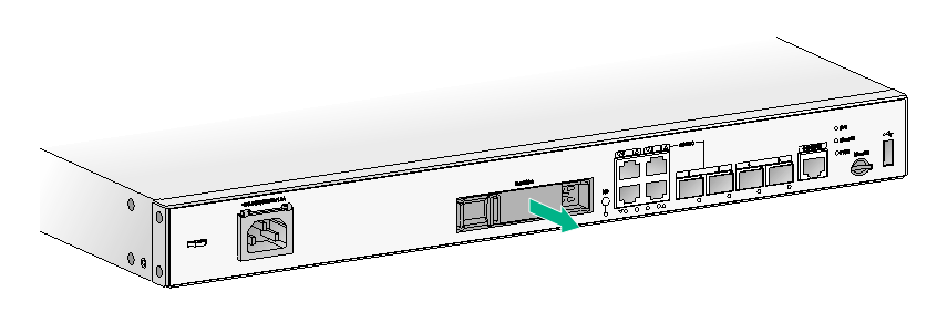
Figure2-50 Installing the SATA drive
Installing an SSD drive
Only the MSR3620-DP and MSR3620-XS routers support mSATA SSD drives. SSD drives are not provided. Prepare one yourself as needed.
Before installing an SSD drive, remove the chassis cover. See "Removing chassis covers."
To install an SSD drive:
1. Locate the SSD drive slot on the MSR3620-DP or MSR3620-XS router. See "Locating internal modules."
2. Align the golden plating on the SSD drive with the mSATA connector in the slot.
3. Slightly press the SSD drive until it is level with the surface of the connector.
4. Use a Phillips screwdriver to screw the SSD drive into place.
Figure2-51 Installing an SSD drive
Logging in from the console port
You can log in to the following routers from the console port only by using a console cable:
· MSR3610-G
· MSR3610-X1
· MSR3610-XS
· MSR3610-X1-DP
· MSR3610-X1-DC
· MSR3610-X1-DP-DC
· MSR3610E-X1
· MSR3610E-X1-DP
· MSR3620-G
· MSR3620-X1
· MSR3620-X1-XS
· MSR3620-DP
· MSR3620-XS
· MSR3640-G
· MSR3640-X1
· MSR3640-XS
· MSR3640-X1-H1
· MSR3660-XS
· MSR3600-28
· MSR3600-28-SI
· MSR3600-28-SI-GL
· MSR3600-28-X1
· MSR3600-28-X1-DP
· MSR3600-28-XS
· MSR3600-51
· MSR3600-51-SI
· MSR3600-51-X1
· MSR3600-51-X1-DP
· MSR3600-28-G-DP
· MSR3600-51-G-DP
You can log in the other routers through the console port by using a console or USB console cable at the first login.
Connecting a console cable
Console cable
No console cables are provided with the router. Prepare a console cable yourself as needed.
As shown in Table2-4, two types of console cables can be used for connecting a configuration terminal to the console port on the router.
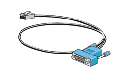
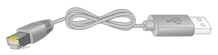
Table2-4 Console cables for connecting the console port
|
Console cable type |
Console cable view |
Router-side connector |
Configuration terminal-side connector |
Connection method |
|
DB9-to-RJ45 console cable |
|
DB-9 female connector |
RJ-45 |
|
|
USB-to-RJ45 console cable |
|
USB |
RJ-45 |
Connecting a DB9-to-RJ45 console cable
|
|
IMPORTANT: · The serial ports on PCs do not support hot swapping. To connect a PC to an operating router, first connect the PC end. To disconnect a PC from an operating router, first disconnect the router end. · If the PC does not have an RS-232 port but has a USB port, install a USB-to-RS-232 converter on the USB port and install the required USB console driver program. |
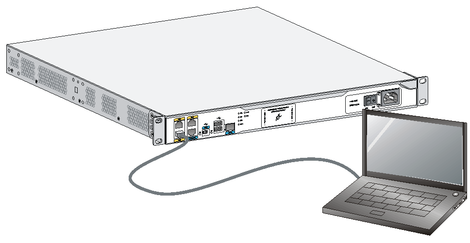
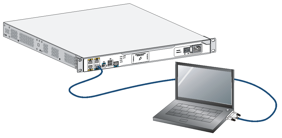
To connect the router to a configuration terminal by using a DB9-to-RJ45 console cable:
1. Plug the DB-9 female connector to the RS-232 port on the configuration terminal.
2. Connect the RJ-45 connector to the console port on the router.
Figure2-52 Connecting the serial port console cable
Connecting a USB-to-RJ45 console cable
|
|
IMPORTANT: · To use a USB-to-RJ45 console cable to connect the router to a configuration terminal, first download and install the USB-to-RJ45 console driver on the configuration terminal, and then connect the USB-to-RJ45 console cable to the configuration terminal. To download the USB-to-RJ45 console driver, access the H3C official website or scan the QR code on the cable package. · If you have connected a USB-to-RJ45 console cable to the configuration terminal before installing the driver, remove and reconnect the USB-to-RJ45 console cable to the configuration terminal after driver installation. |
The following installs the driver on the Windows system. To install the driver on other operating systems, see the installation guide in the driver compression package named by using the corresponding operating system.
To connect the router to a configuration terminal by using a USB-to-RJ45 console cable:
1. Click the following link, or copy it to the address bar on your browser and download the USB-to-RJ45 console driver.
http://www.h3c.com/en/home/USB_to_RJ45_Console/
2. View the TXT file Read me in the Windows folder to check whether the Windows system of the configuration terminal supports the driver.
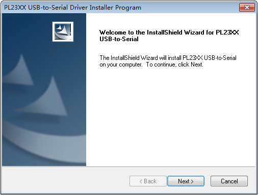
3. If the Windows system supports the driver, install PL23XX-M_LogoDriver_Setup_v200_20190815.exe.
4. Click Next on the welcome page of the driver installation wizard.
Figure2-53 Driver installation wizard
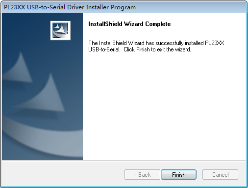
5. Click Finish after the drive installation is completed.
Figure2-54 Finishing the driver installation
6. Connect the standard USB connector of the cable to the USB port on the configuration terminal.
7. Connect the RJ-45 connector of the cable to the console port on the router.
Connecting a USB console cable
|
|
IMPORTANT: Download and install the USB console driver program before configuring the device when you connect the device through a USB console cable. |
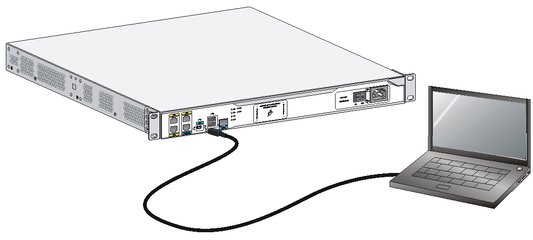
To connect a USB console cable:
1. Connect the USB port to the PC.
2. Connect the other end to the USB console port of the router.
Figure2-55 Connecting the USB console cable
3. Click the following link, or copy it to the address bar on the browser to log in to download page of the USB console driver, and download the driver.
http://www.h3c.com/en/support/resource_center/hk/routers/usb_console/usb_console/?tbox=Software
4. Select a driver program according to the operating system you use:
¡ XR21V1410_XR21B1411_Windows_Ver1840_x86_Installer.EXE—Applicable to 32-bit operating systems.
¡ XR21V1410_XR21B1411_Windows_Ver1840_x64_Installer.EXE—Applicable to 64-bit operating systems.
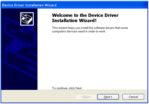
5. Click Next on the installation wizard.
Figure2-56 Device Driver Installation Wizard
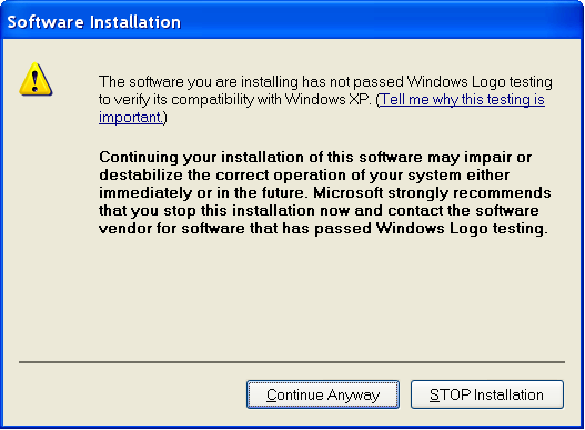
6. Click Continue Anyway if the following dialog box appears.
Figure2-57 Software Installation
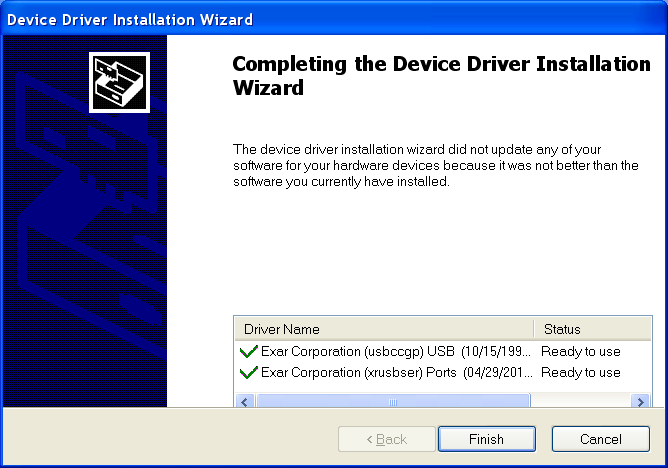
7. Click Finish.
Figure2-58 Completing the device driver installation wizard
Setting terminal parameters
To access the device through the console port, you must run a terminal emulator program (HyperTerminal, PuTTY, or Tera Term) on the configuration terminal. For information about using a terminal emulator program, see the program's user guide.
The following are the required terminal settings:
· Baud rate—9600.
· Data bits—8.
· Stop bits—1.
· Parity—none.
· Flow control—none.
Installing a power supply
|
|
IMPORTANT: · The MSR 36-40 and MSR 36-60 routers support AC power supplies, DC power supplies, and PoE power supplies. · The MSR3610-G, MSR3620-G, MSR3600-51, MSR3620-X1, MSR3620-X1-XS, MSR3620-DP, MSR3620-XS, MSR3640-G, MSR3640-X1, MSR3640-XS, MSR3640-X1-H1, and MSR3660-XS routers support AC and DC power supplies. · You cannot install AC and DC power supplies on the same router. · The MSR 3600 routers support hot swapping of power supplies. |
Installing an AC/DC power supply
1. Face the front of the router and locate the slot to be used.
2. Loosen the captive screws with a Phillips screwdriver to remove the filler panel from the slot.
Keep the removed filler panel for future use.
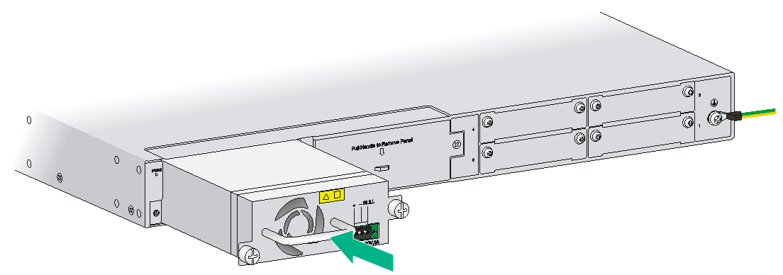
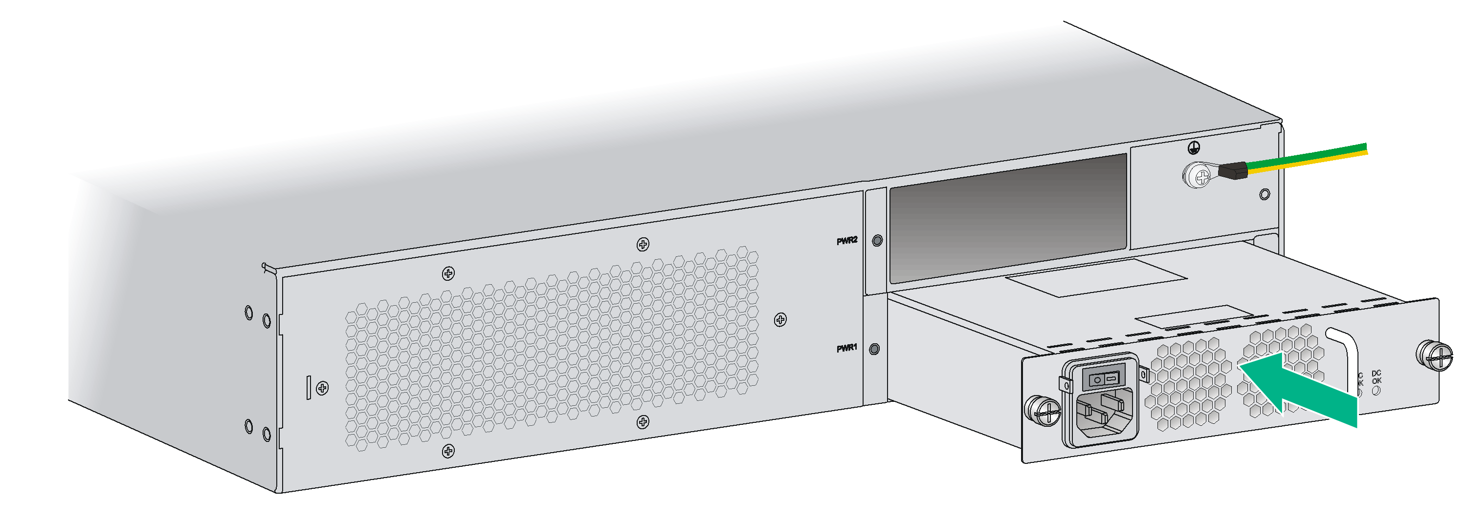
Skip this step if the router is shipped with this slot empty.
3. Holding the handle of the power supply with one hand and supporting the bottom of the power supply with the other hand, insert the power supply slowly along the slide rails until it makes close contact with the backplane.
4. Use a Phillips screwdriver to fasten the captive screws on the two sides of the power supply.
Figure2-59 Installing an AC power supply (MSR 36-40/MSR 36-60/MSR3640-G/MSR3640-X1/MSR3640-XS/MSR3640-X1-H1/MSR3660-XS)

Figure2-60 Installing an AC power supply (MSR3610-G/MSR3620-G/MSR3620-DP/MSR3600-51/MSR3620-XS/MSR3620-X1/MSR3620-X1-XS)
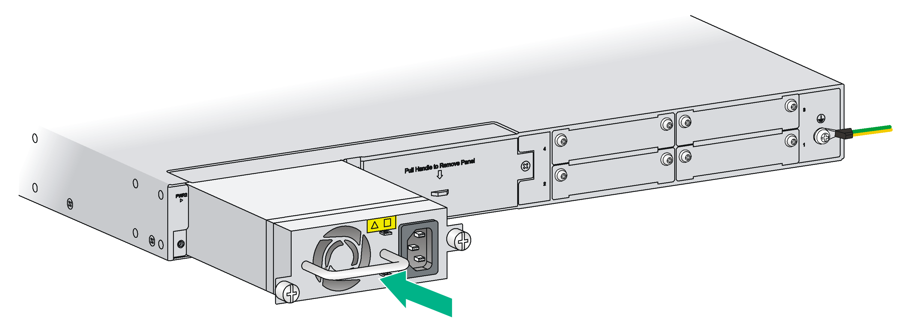
Figure2-61 Installing a DC power supply (MSR 36-40/MSR 36-60/MSR3640-G/MSR3640-X1/MSR3640-XS/MSR3640-X1-H1/MSR3660-XS)
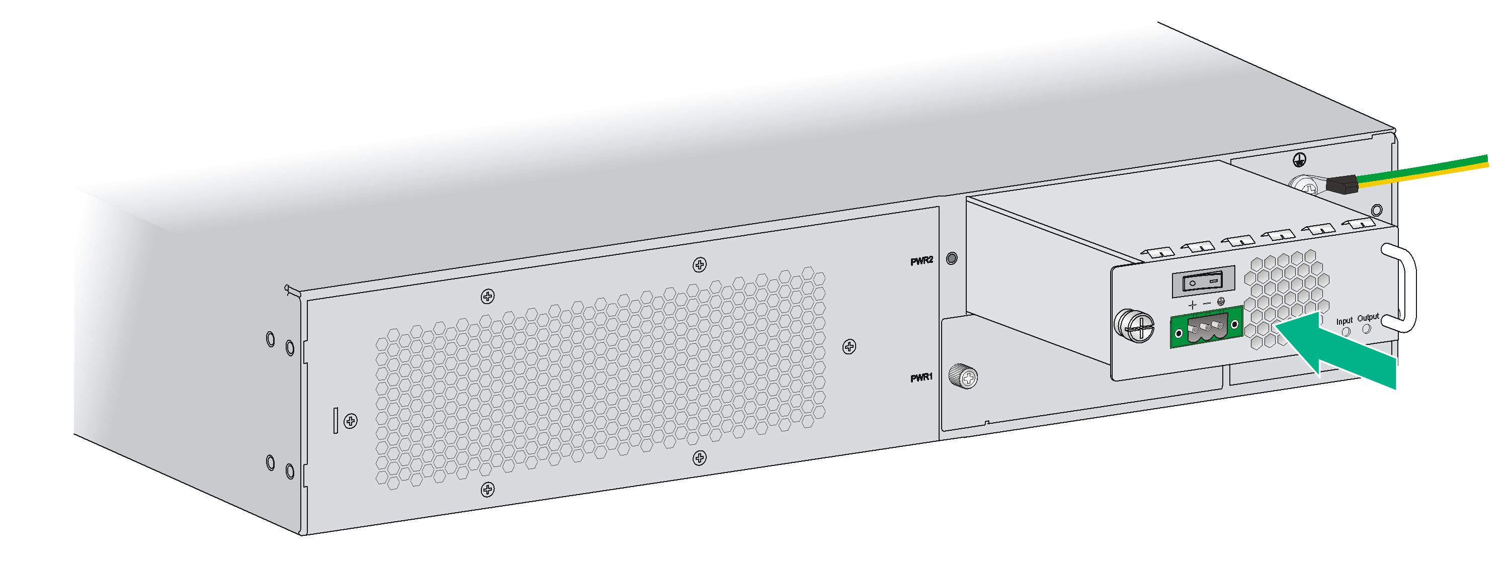
Figure2-62 Installing a DC power supply (MSR3610-G/MSR3620-G/MSR3620-X1/MSR3620-X1-XS/MSR3620-DP/MSR3620-XS/MSR3600-51)
Installing a PoE power supply
1. Face the front of the router and locate the slot to be used.
2. Loosen the captive screws with a Phillips screwdriver to remove the filler panel from the slot.
Keep the removed filler panel for future use.
Skip this step if you install the power supply to the PWR1 slot.
3. Holding the handle of the power supply with one hand and supporting the bottom of the power supply with the other hand, insert the power supply slowly along the slide rails until it makes close contact with the backplane.
4. Use a Phillips screwdriver to fasten the captive screws on the two sides of the power supply.
Figure2-63 Installing a PoE power supply
Connecting the power cord
The power cords in these figures are for illustration only. For routers that have two power receptacles, you can connect two power cords for 1+1 redundancy.
Connecting an AC power cord
1. Make sure the router is correctly grounded, and the power switch on the router is in the OFF position.
2. Connect one end of the AC power cord to the AC receptacle on the router, and the other end to the AC power source.
Figure2-64 Connecting an AC power cord to an MSR 36-10/MSR 36-20/MSR 36-40/MSR 36-60/MSR3640-G/MSR3640-X1/MSR3640-XS/MSR3640-X1-H1/MSR3660-XS router
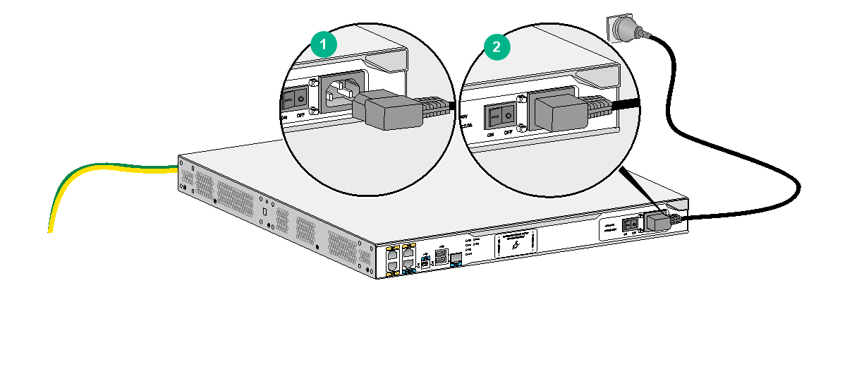
Figure2-65 Connecting an AC power cord to an MSR3600-28 router
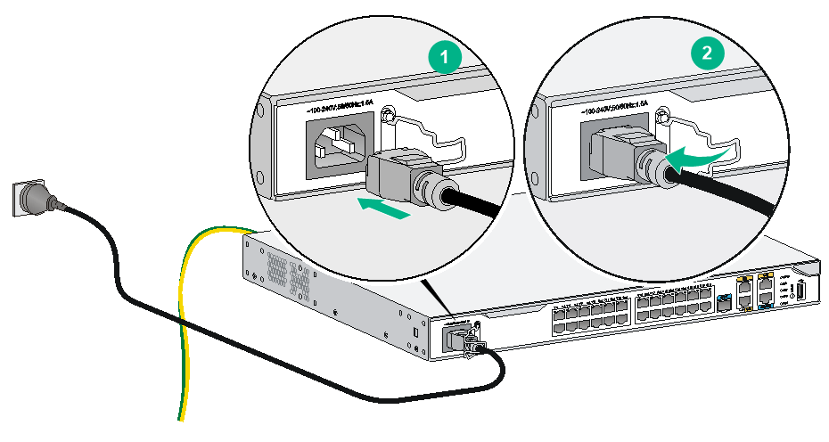
Figure2-66 Connecting an AC power cord to an MSR3610-G/MSR3620-G/MSR3620-X1/MSR3620-X1-XS/MSR3620-DP/MSR3620-XS/MSR3600-51 router
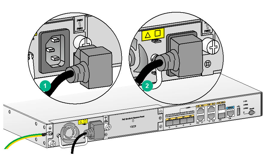
Figure2-67 Connecting an AC power cord to an MSR3610-X1/MSR3610-XS/MSR3600-28-SI/MSR3600-28-SI-GL/MSR3600-28-X1/MSR3600-51-SI/MSR3600-28-XS/MSR3600-51-X1 router
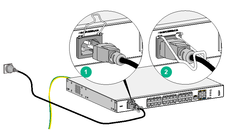
Figure2-68 Connecting an AC power cord to an MSR3610-X1-DP/MSR3600-28-X1-DP/MSR3600-51-X1-DP router
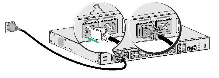
Figure2-69 Connecting an AC power cord to an MSR3610E-X1/MSR3610E-X1-DP/MSR3600-28-G-DP/MSR3600-51-G-DP router
Connecting a DC power cord
|
|
WARNING! Pay attention to the mark on a power cord to avoid connection errors. |
The following routers do not support DC input:
· MSR3610-X1
· MSR3610-XS
· MSR3610-X1-DP
· MSR3610E-X1
· MSR3610E-X1-DP
· MSR3600-28
· MSR3600-28-SI
· MSR3600-28-SI-GL
· MSR3600-28-X1
· MSR3600-28-X1-DP
· MSR3600-28-XS
· MSR3600-51-SI
· MSR3600-28-G-DP
· MSR3600-51-G-DP
The MSR 36-10, MSR 36-20, MSR3610-G, MSR3610-X1-DC, MSR3610-X1-DP-DC, MSR3620-G, MSR3620-X1, MSR3620-X1-XS, MSR 3620-DP, MSR3620-XS, MSR 36-40, MSR 36-60, MSR3640-G, MSR3640-X1, MSR3640-XS, MSR3640-X1-H1, MSR3660-XS, and MSR3600-51 routers support DC input and use similar DC power cord connection procedures. As a best practice, use the DC power cord provided with the router.
To connect the DC power cord for an MSR 36-10, MSR 36-20, MSR3610-G, MSR3610-X1-DC, MSR3610-X1-DP-DC, MSR3620-G, MSR3620-X1, MSR3620-X1-XS, MSR3620-DP, MSR3620-XS, MSR 36-40, MSR 36-60, MSR3640-G, MSR3640-X1, MSR3640-XS, MSR3640-X1-H1, MSR3660-XS, or MSR3600-51 router:
1. Make sure the router is correctly grounded, and the power switch on the router, if any, is in the OFF position.
Only the power supplies applicable to an MSR 36-10/MSR 36-20 router or MSR 36-40/MSR 36-60 router provide a power switch.
2. Loosen the captive screws on the power supply with a Phillips screwdriver to remove the power supply connector.
3. Connect one end of the DC power cord supplied with the router to the DC receptacle on the router, and the other end to a DC power source.
Figure2-70 Connecting a DC power cord for an MSR 36-10/MSR 36-20 router
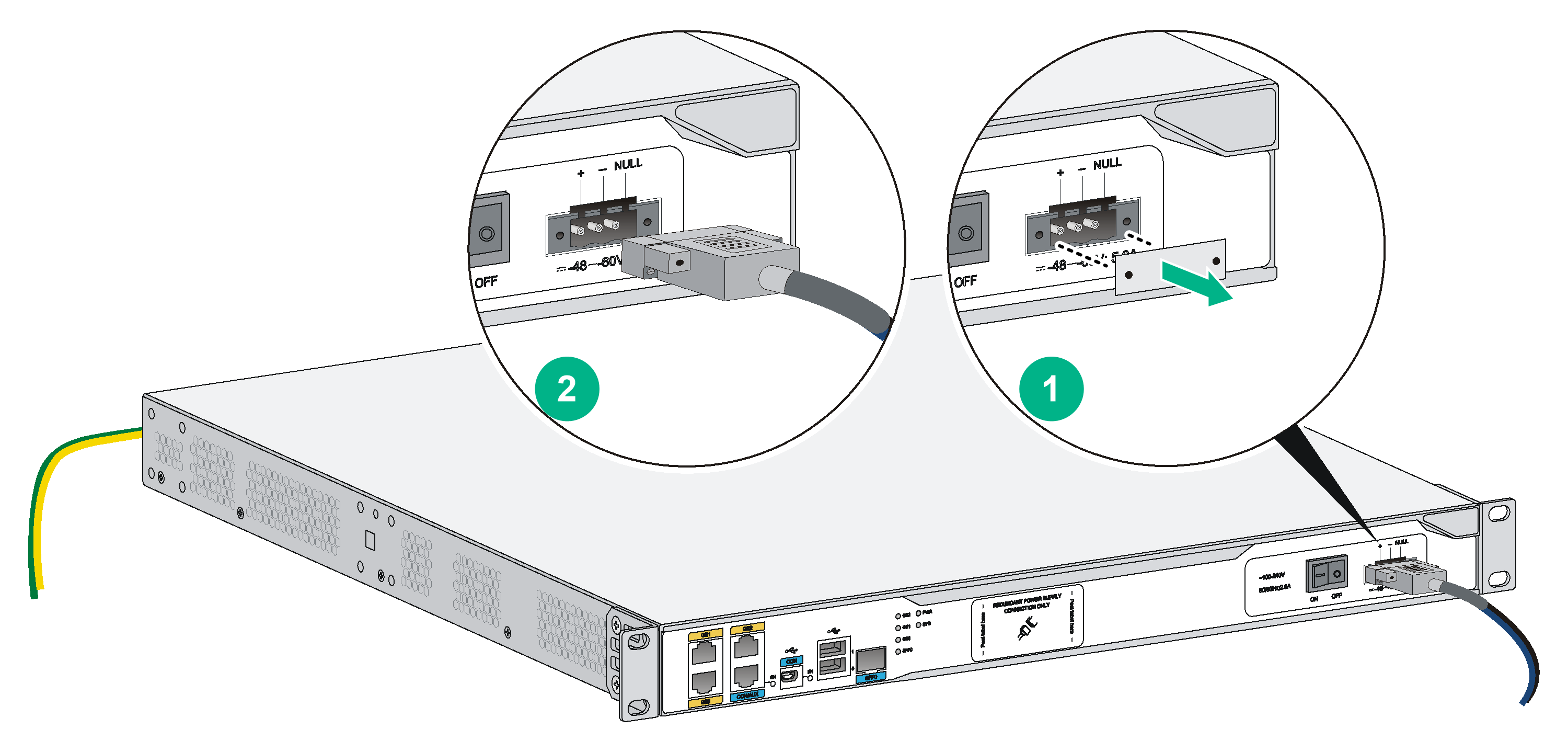
Figure2-71 Connecting a DC power cord for an MSR 36-40/MSR 36-60/MSR3640-G/MSR3640-X1/MSR3640-XS/MSR3640-X1-HI/MSR3660-XS router
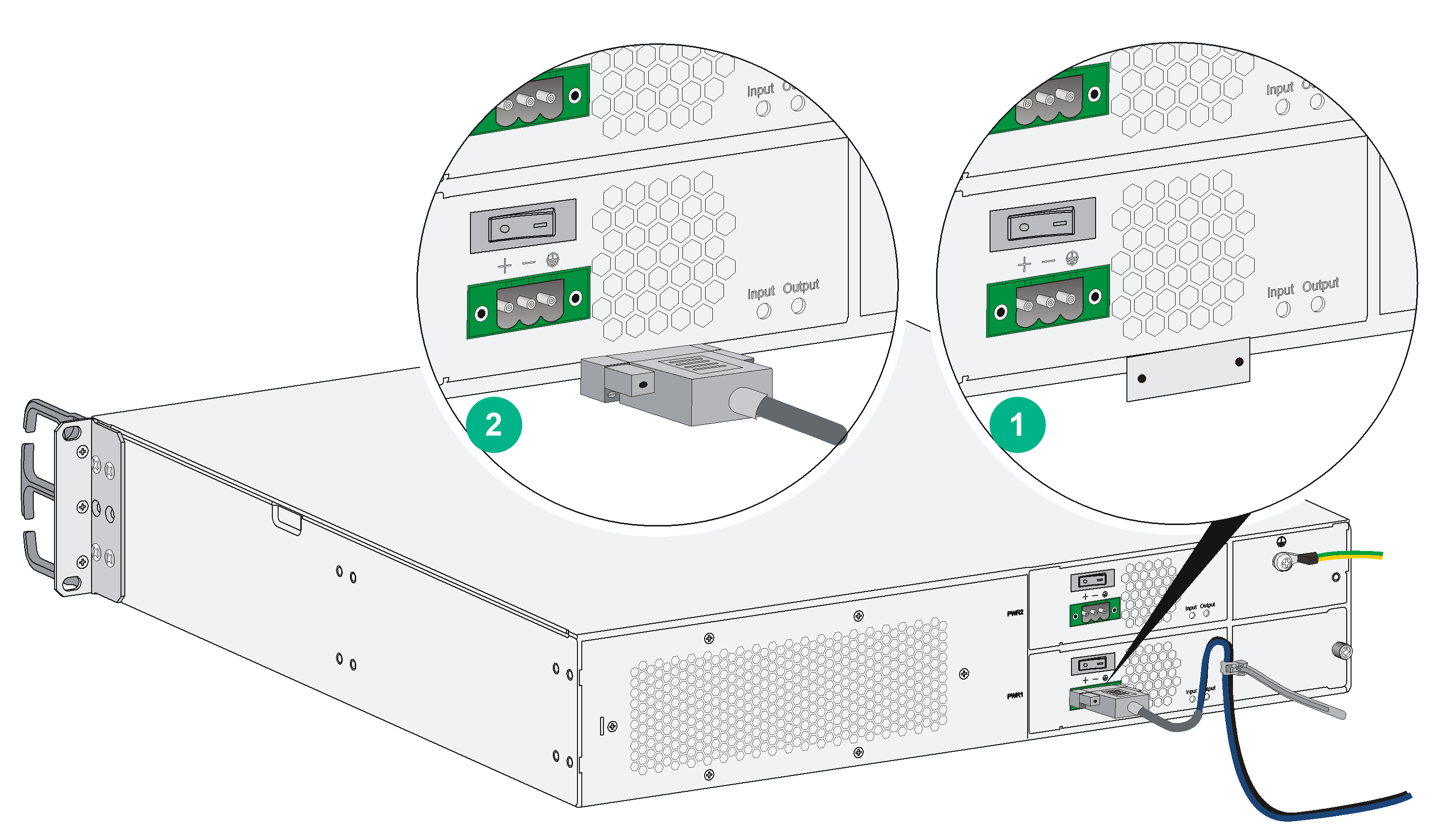
Figure2-72 Connecting a DC power cord for an MSR3610-X1-DC/MSR3610-X1-DP-DC router
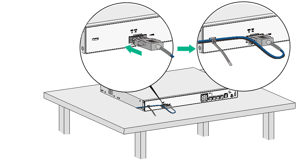
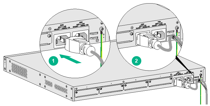
Figure2-73 Connecting a DC power cord for an MSR3610-G/MSR3620-G/MSR3600-51/MSR3620-X1/MSR3620-X1-XS/MSR3620-DP/MSR3620-XS router
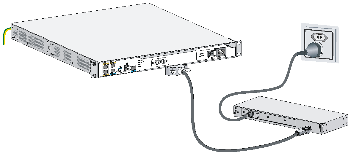
Connecting an RPS power cord
The MSR 36-10 and MSR 36-20 routers support remote power supply (RPS). As an external power supply, RPS can provide power supply for the device in case of power supply abnormality. It enhances the reliability of the device.
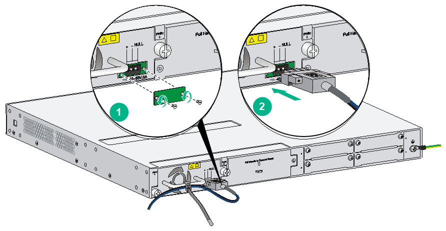
The router has a sticky label and a protective cover when shipped to protect the RPS receptacle.
To connect an RPS power cord:
1. Remove the sticky label.
2. Remove the screws on the protective cover with a screw driver to remove the protective cover, as shown in Figure2-74.
3. Insert one end of the RPS power cord to the RPS receptacle on the router and fasten the screws on the RPS power cord plug.
4. Make sure the RPS power is OFF and connect the other end of the power cord to the RPS power source.
Figure2-74 Removing the sticky label and protective cover
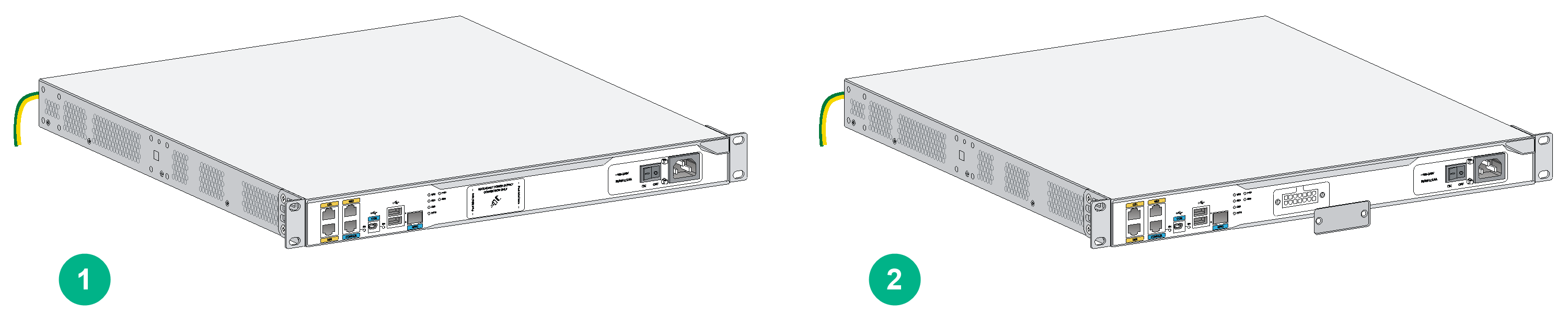
Figure2-75 Connecting the RPS power cord
Verifying the installation
After you complete the installation, verify the following information:
· There is enough space for heat dissipation around the router, and the rack or workbench is stable.
· USB devices and interface modules are correctly installed.
· The router, rack, and power cords are correctly grounded.
· The correct power source is used.
· The router is connected correctly to the console terminal and other devices.
Accessing the router for the first time
|
WARNING! Before powering on the router, locate the switch for the power source so that you can cut off power promptly in case of an emergency. |
|
|
CAUTION: To avoid device damage, you must perform the following steps if you fail to start the MSR3610-G or MSR3620-G router: 1. Power off the router. 2. Remove the label from the Micro SD card slot. 3. Reinstall the Micro SD card. 4. Restart the router. |
For a router starting with empty configuration, you must press Ctrl+D to access the CLI.
To access the router for the first time:
1. Verify that the installation and configuration environment is as described in "Verifying the installation."
2. Power on the router.
3. During the booting process, verify the following items:
¡ The LEDs on the front panel are in the states as described in Table2-5.
Table2-5 LED states when the router is operating correctly
|
LED |
State |
Description |
|
PWR |
Steady green |
The power supply is supplying power correctly. |
|
SYS |
Slow flashing green |
The router is operating correctly. |
¡ The configuration terminal displays information correctly.
The router first initializes its memory at startup and then runs BootWare.
System is starting...
Press Ctrl+D to access BASIC-BOOTWARE MENU...
Press Ctrl+T to start heavy memory test
Booting Normal Extended BootWare........
The Extended BootWare is self-decompressing....Done.
****************************************************************************
* *
* H3C MSR36-40 BootWare, Version 1.60 *
* *
****************************************************************************
Copyright (c) 2004-2018 New H3C Technologies Co., Ltd.
Compiled Date : Dec 23 2015
CPU ID : 0x2
Memory Type : DDR3 SDRAM
Memory Size : 2048MB
BootWare Size : 1024KB
Flash Size : 8MB
cfa0 Size : 247MB
CPLD Version : 2.0
PCB Version : 2.0
BootWare Validating...
Press Ctrl+B to access EXTENDED-BOOTWARE MENU...
Loading the main image files...
Loading file cfa0:/msr36-cmw710-system-e0006p05.bin.........................
.............Done.
Loading file cfa0:/msr36-cmw710-security-e0006p05.bin...Done.
Loading file cfa0:/msr36-cmw710-voice-e0006p05.bin......Done.
Loading file cfa0:/msr36-cmw710-data-e0006p05.bin.....Done.
Loading file cfa0:/msr36-cmw710-boot-e0006p05.bin...............Done.
Image file cfa0:/msr36-cmw710-boot-e0006p05.bin is self-decompressing.......
.......Done.
System image is starting...
Line aux0 is available.
Press ENTER to get started.
4. Press Enter. The router is ready to configure when you see the following prompt:
<H3C>
5. Configure basic settings for the router. For more information, see the configuration guide for the router.
3 Replacement procedure
|
IMPORTANT: · The barcode on the router chassis contains product information that must be provided to local sales agent when you return a faulty router for service. · Keep the tamper-proof seal on a mounting screw on the chassis cover intact, and if you want to open the chassis, contact H3C for permission. Otherwise, H3C shall not be liable for any consequence. |
Replacing a power supply
Power supplies are hot swappable.
The replacement procedure of an AC power supply and a DC power supply is the same. This section uses an AC power supply on the MSR 36-40/MSR 36-60 router as an example.
To replace a power supply:
1. Locate the power supply to be removed and use a Phillips screwdriver to completely loosen the captive screws of the power supply.
2. Holding the handle of the power supply with one hand and supporting the bottom of the power supply with the other hand, gently pull the power supply out of the slot along the slide rails.
Put the removed power supply on an antistatic workbench or into an antistatic bag.
Figure3-1 Pulling a power supply out of the slot
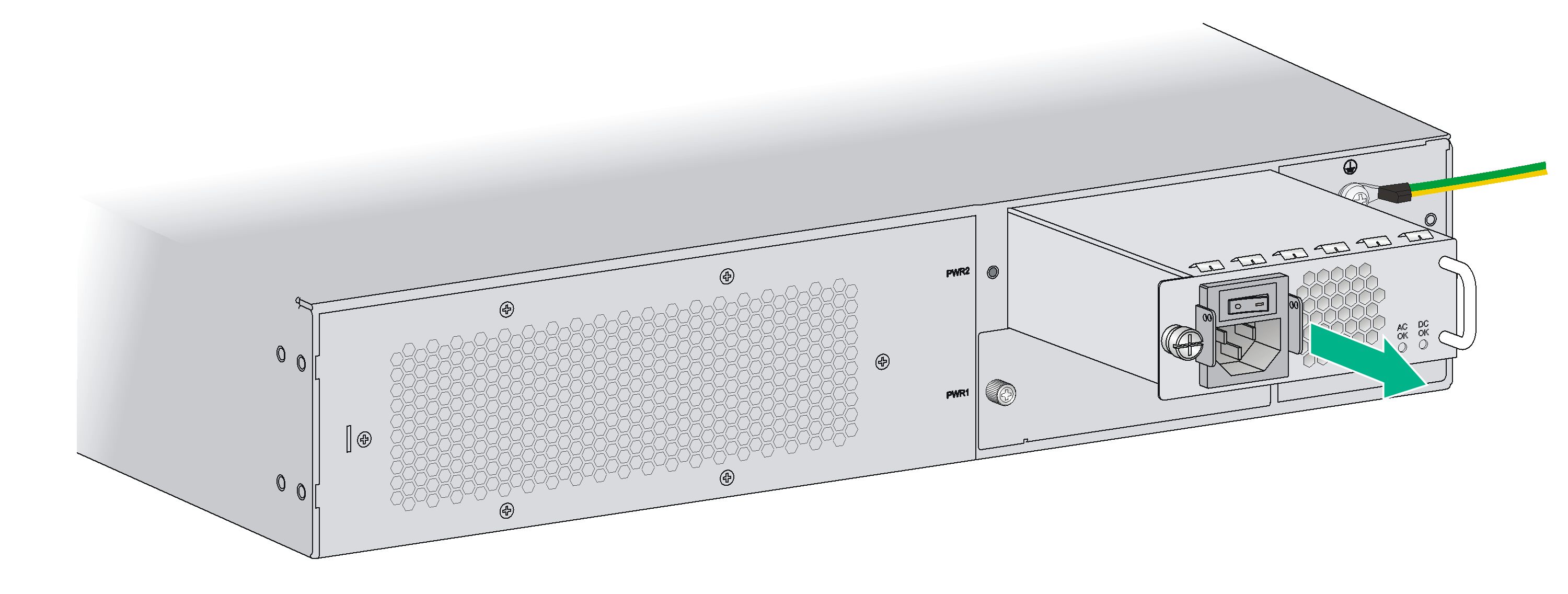
3. Install a new power supply. For the installation procedure, see "Installing a power supply."
Install a filler panel if you do not install a new power supply.
Locating internal modules
Removing chassis covers
|
|
WARNING! · To avoid bodily injury and equipment damage, make sure all power supplies connected to the router are powered off, all power cords and interface cables are removed before you maintain the hardware. · Wear an ESD wrist and make sure it makes good skin contact and is correctly grounded. · After you maintain the hardware, reinstall the chassis cover. |
The hardware components of the following router chassis are not replaceable:
· MSR3610-G
· MSR3610-X1
· MSR3610-XS
· MSR3610-X1-DP
· MSR3610-X1-DC
· MSR3610-X1-DP-DC
· MSR3610E-X1
· MSR3610E-X1-DP
· MSR3620-G
· MSR3620-X1
· MSR3620-X1-XS
· MSR3600-28
· MSR3600-28-SI
· MSR3600-28-SI-GL
· MSR3600-28-X1
· MSR3600-28-X1-DP
· MSR3600-28-XS
· MSR3600-51
· MSR3600-51-SI
· MSR3600-51-X1
· MSR3600-51-X1-DP
· MSR3640-G
· MSR3640-X1
· MSR3640-XS
· MSR3640-X1-H1
· MSR3660-XS
· MSR3600-28-G-DP
· MSR3600-51-G-DP
As a best practice, do not open the chassis cover of the above routers.
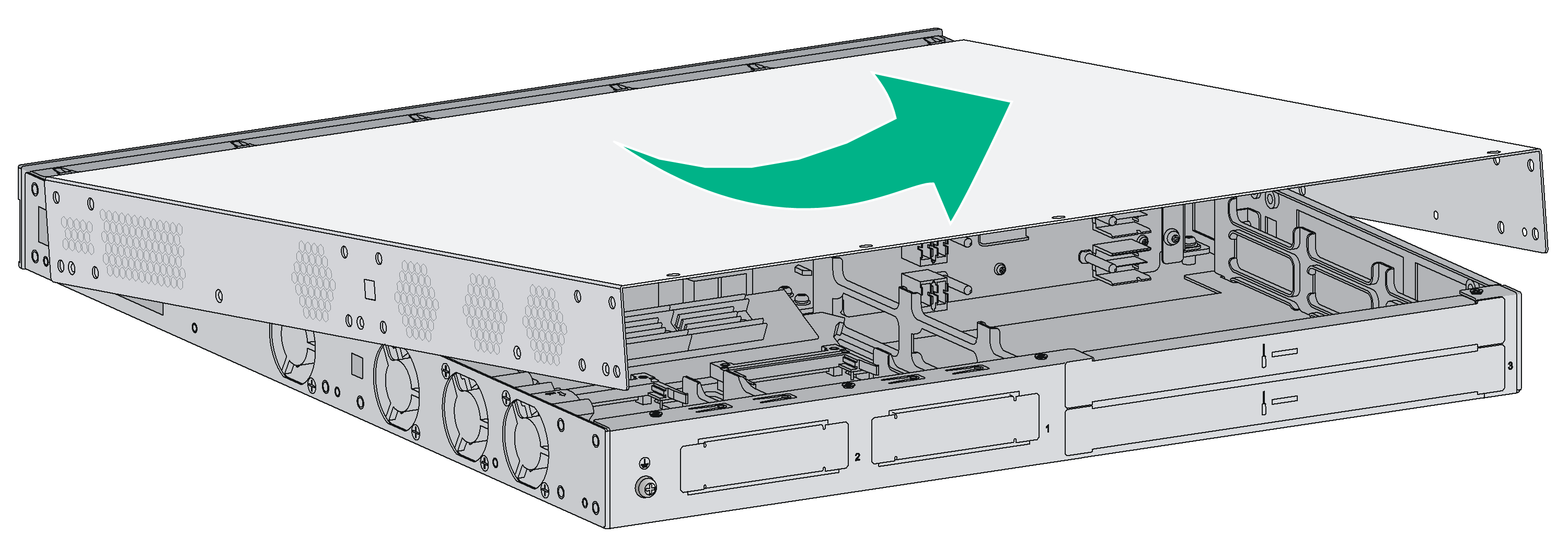
Removing the chassis cover from an MSR 36-10/MSR 36-20/MSR3620-DP/MSR 3620-XS
1. Place the router on a flat surface and have the rear panel face you.
2. Use a Phillips screwdriver to remove the cover screws on the chassis sides and on the rear panel top.
3. Rotate a flat-blade screwdriver to separate the chassis and the cover as shown in Figure3-3.
4. Raise the chassis cover until its front edge is separated from the chassis bottom completely.
5. Pull the chassis cover towards you until the tab on the back edge is disengaged from the front panel.
Figure3-2 Removing the screws from the chassis cover
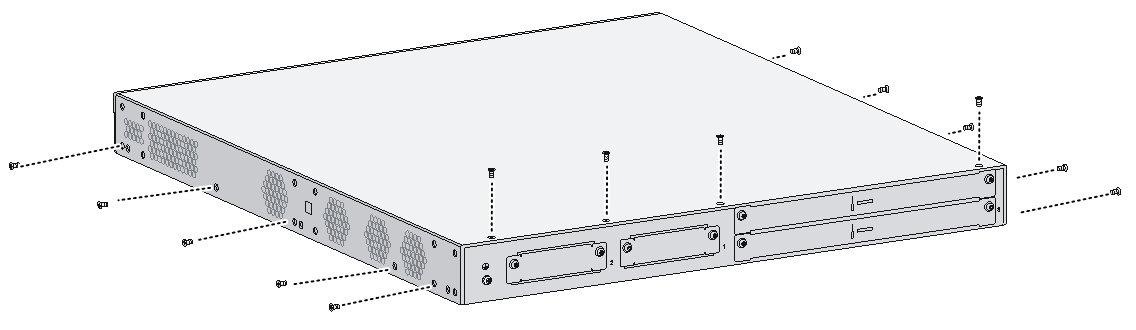
Figure3-3 Rotating the flat-blade screwdriver
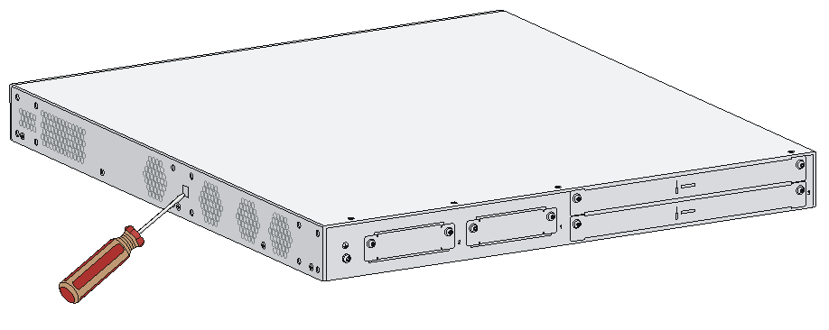
Figure3-4 Lifting the chassis cover
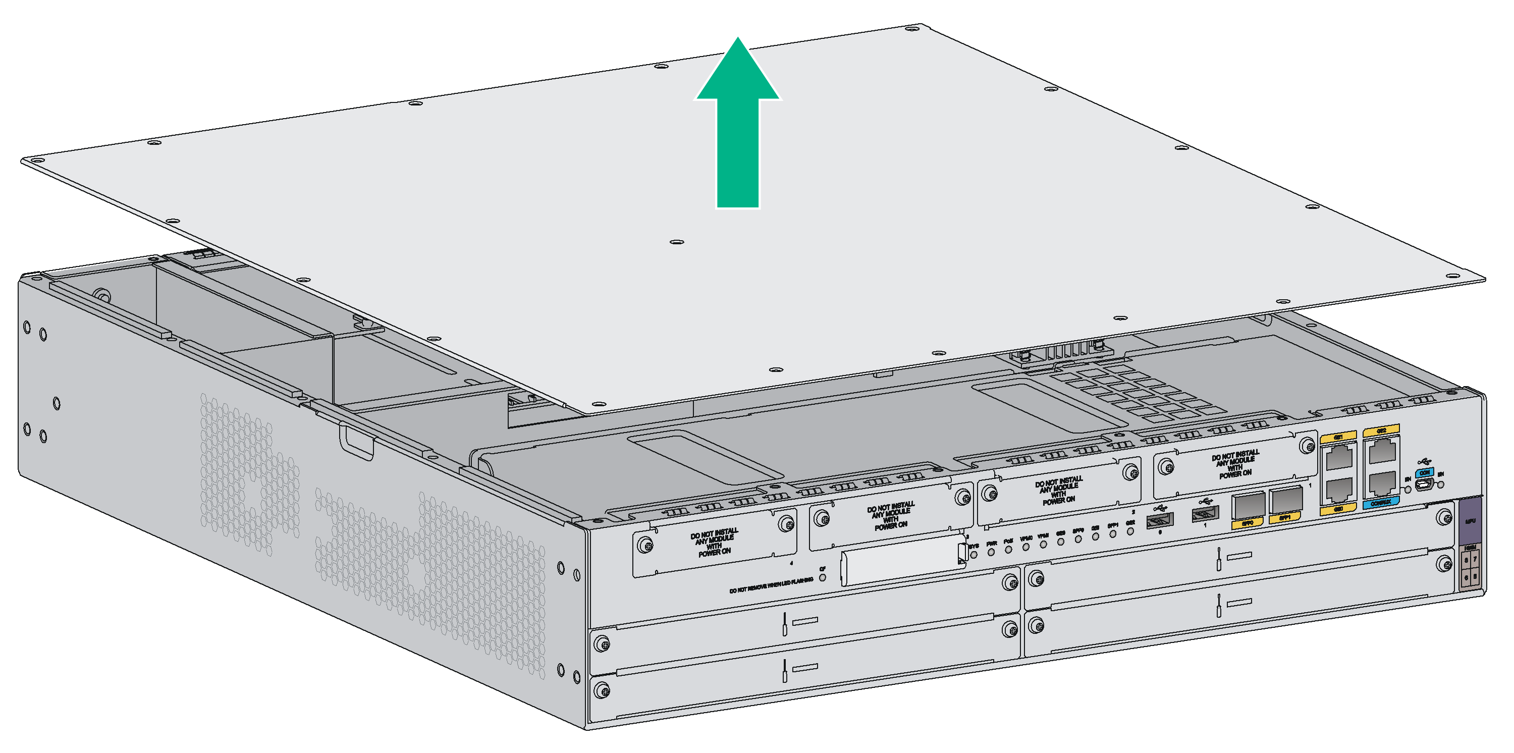
Removing the chassis cover from the MSR 36-40/MSR 36-60
1. Place the router on a flat surface.
2. Use a Phillips screwdriver to remove the fastening screws at the top of the router from chassis cover.
3. Lift the chassis cover and put it away.
Figure3-5 Removing the screws from the chassis cover
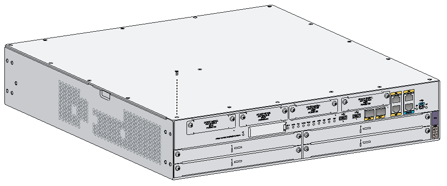
Figure3-6 Lifting the chassis cover
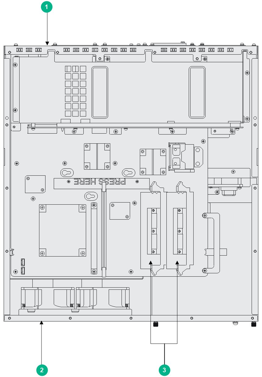
Locating internal modules
Figure3-7 MSR 36-10 internal module locations
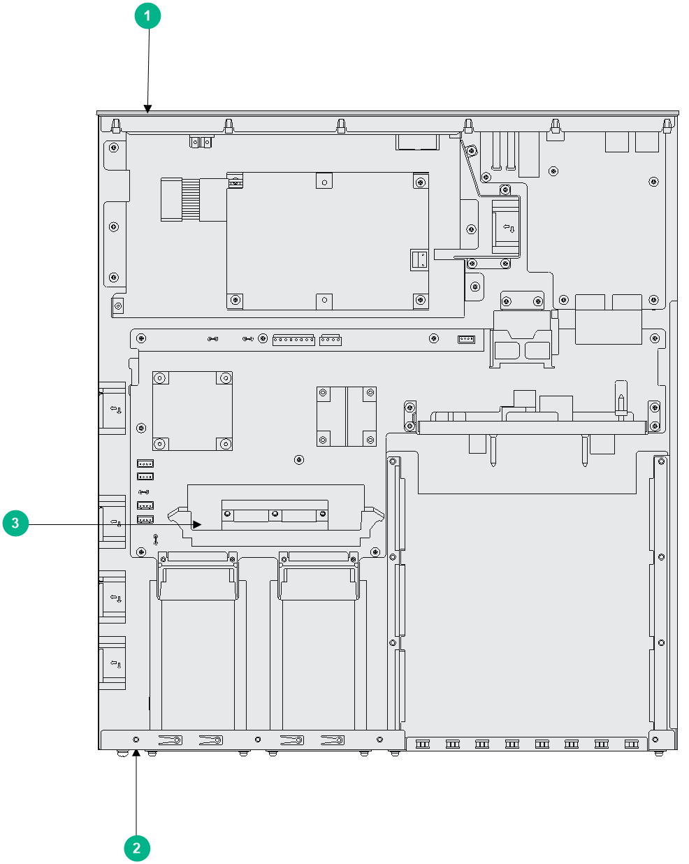
|
(1) Front panel |
(2) Rear panel |
(3) VPM |
Figure3-8 MSR 36-20 internal module locations
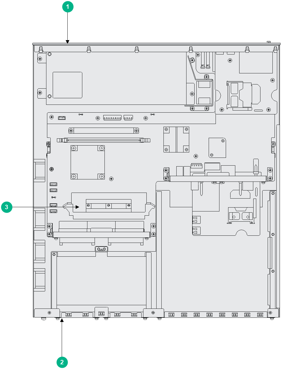
|
(1) Front panel |
(2) Rear panel |
(3) VPM |
Figure3-9 MSR3620-DP/MSR3620-XS internal module locations
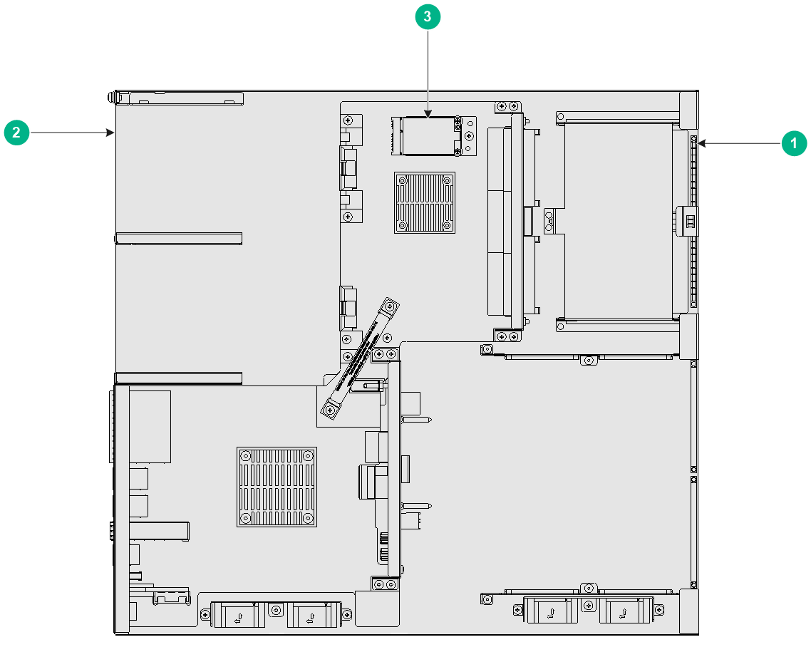
|
(1) Front panel |
(2) Rear panel |
(3) SSD drive slot |
Figure3-10 MSR 36-40 internal module locations
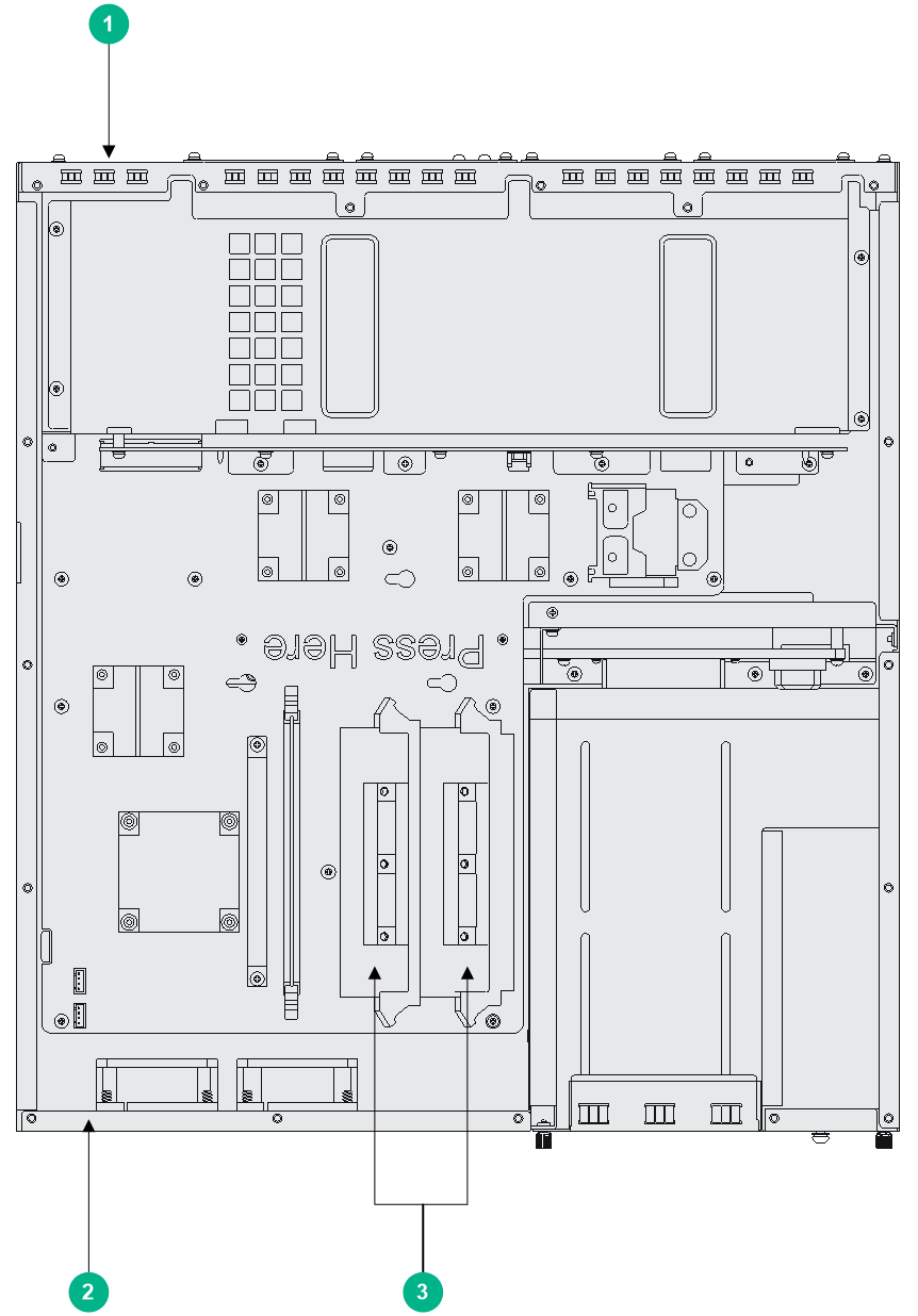
|
(1) Front panel |
(2) Rear panel |
(3) VPMs |
Figure3-11 MSR 36-60 internal module locations
|
(1) Front panel |
(2) Rear panel |
(3) VPMs |
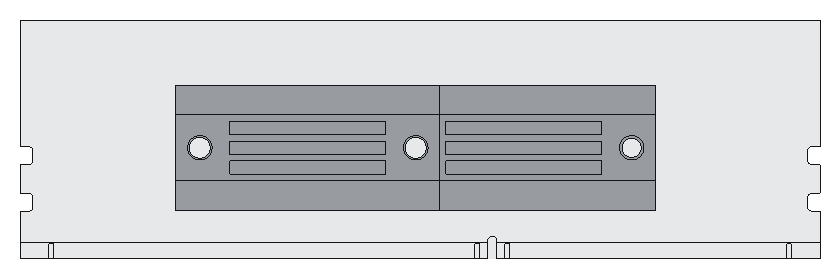
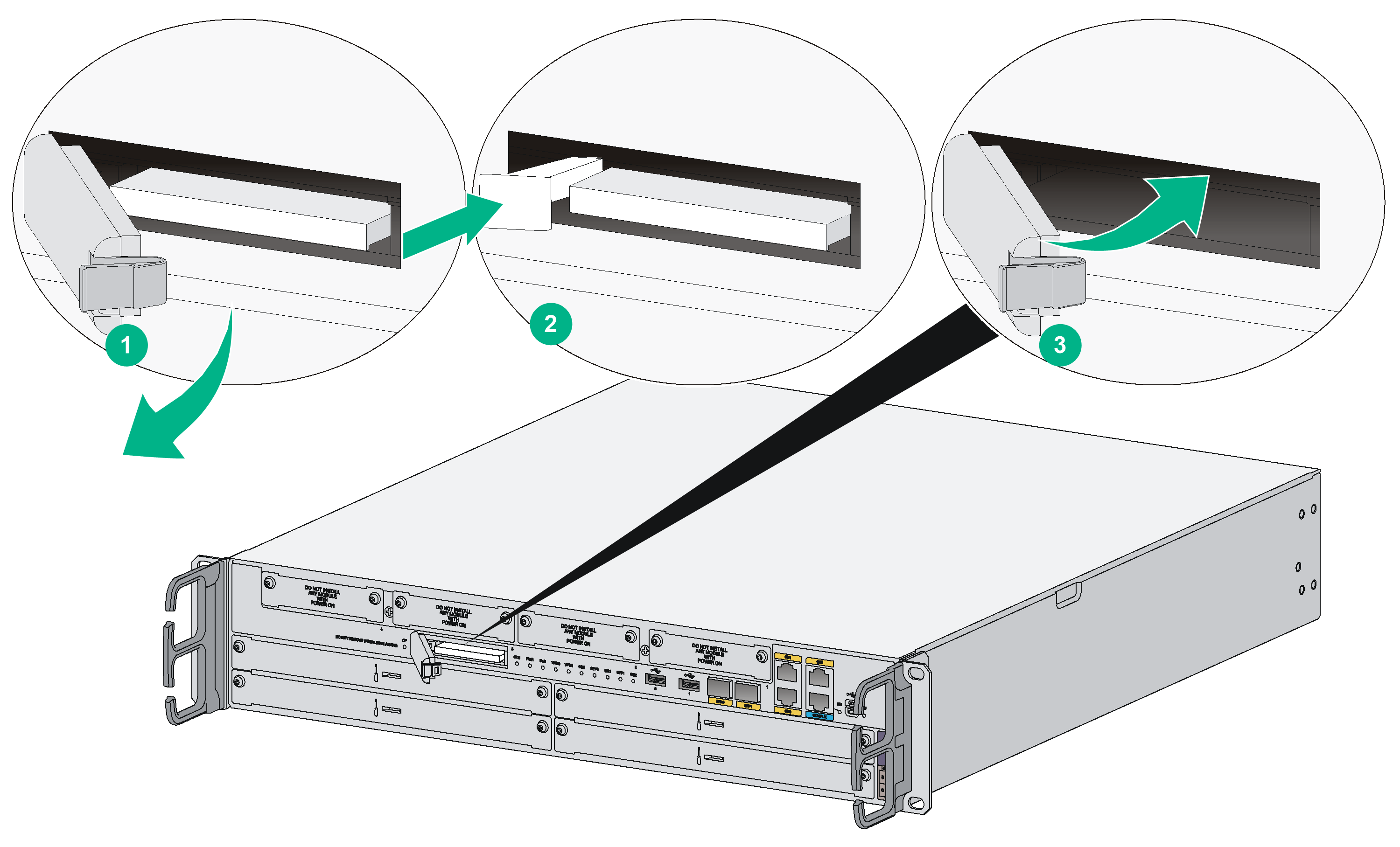
Replacing a VPM
VPM (Voice Processing Module) functions to implement the encryption/decryption, EC and CNG of voices. The following types of VPM modules are available on the MSR 36 routers:
· 256-channel voice processing module (256-VPM)
· 512-channel voice processing module (512-VPM)
1. Pull the release latches away from the VPM at both ends so that the VPM springs up from the slot.
2. Holding the non-conductive edge, remove the VPM.
Keep the removed VPM for future use.
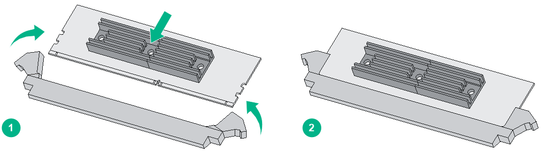
3. Align the polarization notch of a new VPM with the VPM slot on the main board and insert it into the slot along the slide rails.
4. Carefully and firmly press the VPM at both ends until you hear a click. This indicates the VPM is seated in the slot.
5. Verify that the release latches have firmly locked the VPM in position.
Figure3-13 Removing a VPM
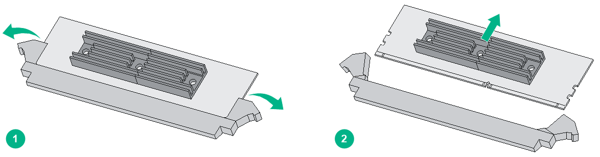
Figure3-14 Installing a VPM
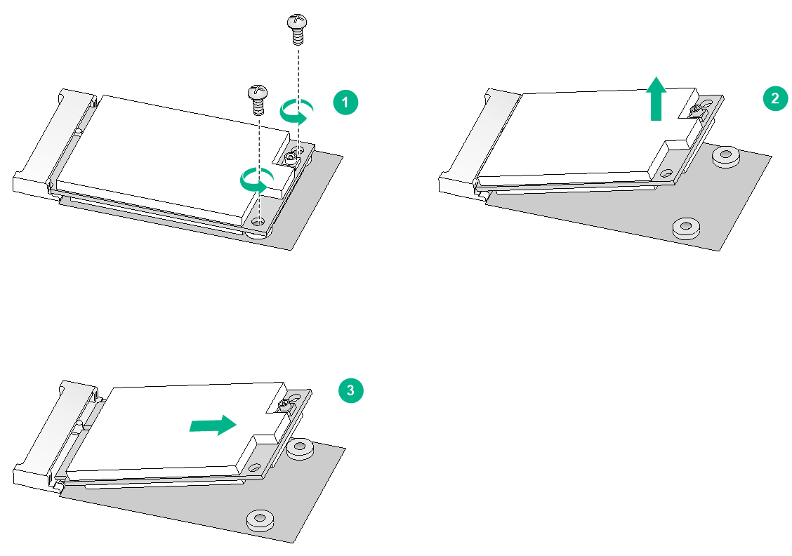
Replacing an SSD drive
1. Use a Phillips screwdriver to remove the fastening screws on the SSD drive.
2. Gently lift the SSD drive free from the connector.
Keep the removed SSD drive safe for future use.
3. To install a new SSD drive, see "Installing an SSD drive."
Figure3-15 Removing an SSD drive
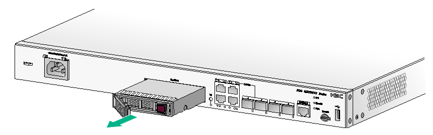
Replacing a SATA drive
|
|
CAUTION: · To remove the SATA drive when the device is operating, press the HD button for over five seconds. When the LED for the SATA drive turns off, you can remove the SATA drive. You can also use the umount command to unmount the file system and remove the SATA drive after the unmount operation succeeds. · After you remove the SATA drive, wait 10 seconds or more before installing a new one to avoid file system corruption. If the file system is corrupted, use the mount command to mount the file system. |
To replace a SATA drive:
1. Press the button on the right side of the SATA drive tray panel to release the ejector lever of the tray.
2. Hold the ejector lever to pull the disk out of the slot.
3. Install a new SATA drive in the slot. For information about the installation procedure, see "Installing a SATA drive."
4. If you are not to install a new SATA drive, install a filler panel in the slot.
Figure3-16 Removing the SATA drive
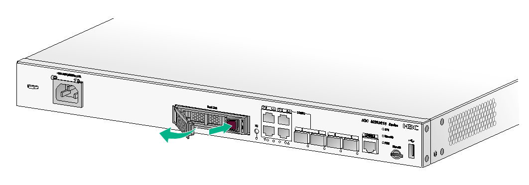
Figure3-17 Installing the SATA drive
Replacing an air filter
1. Use a Phillips screwdriver to completely loosen the captive screws of the air filter.
2. Gently pull the air filter out along the slide rails.
Figure3-18 Removing an air filter
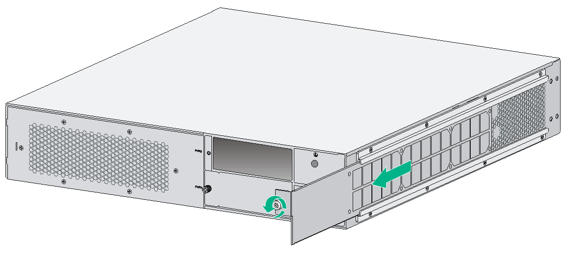
3. Install a new air filter. For the installation procedure, see "Installing an air filter."
To remove the slide rails, completely loosen the fastening screws of the slide rails.
To install new slide rails, see "Installing an air filter."
Figure3-19 Removing slide rails
Replacing a CF card
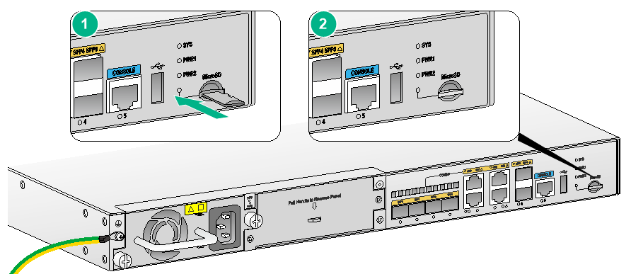
1. Execute the umount cfb0: command and make sure the execution is successful. Skip this step if the router is powered off.
2. Press down the spring clip of the CF card cover and open the cover.
Keep the removed CF card for future use.
Figure3-20 Removing the CF card
4. Install a new CF card. For the installation procedure, see "Installing a CF card."
If you do not install a new CF card, close the CF card cover.
Replacing a label
1. Peel off the label as shown in Figure3-21.
Figure3-21 Peeling off the label
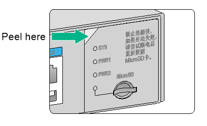
2. Apply a new label in the original position.
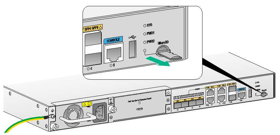
Replacing a Micro SD card
|
|
CAUTION: · To avoid startup failure of the router, do not replace the Micro SD card on an MSR3610-G or MSR3620-G router yourself. If the Micro SD card is damaged, please contact the local sales agent. · The Micro SD card shipped with the MSR3610-G or MSR3620-G router has a system software image file. Do not replace the Micro SD card yourself. Please contact H3C Support. · Micro SD cards on the MSR3610-G and MSR3620-G routers are not hot swappable. · Micro SD cards on the MSR3610-X1, MSR3610-XS, MSR3610-X1-DP, MSR3610-X1-DC, MSR3610-X1-DP-DC, MSR3620-DP, and MSR3620-XS routers are hot swappable. To prevent Micro SD card damage and data loss, execute the umount command before you hot swap a Micro SD card. · To avoid Micro SD card damage, do not use extra force when you replace a Micro SD card. |
To replace a Micro SD card:
1. Execute the umount sdb0: command and make sure the execution is successful. Skip this step if the router is powered off.
2. Pull out the Micro SD card along the guide rails from the slot.
Keep the removed Micro SD card for future use.
3. Install a new Micro SD card. For the installation procedure, see "Installing a Micro SD card."
Figure3-22 Removing the Micro SD card
Replacing a SIC
|
|
CAUTION: · Only SIC modules with remove buttons are hot swappable. To avoid unexpected reboots of the device and unavailability of the interface modules, make sure the router is powered off before installing other SIC modules that are not hot swappable. · To avoid unexpected reboot of the system when you remove a SIC module with a remove button, first execute the remove command or use the remove button. The method of removing a SIC module by using the remove button varies by SIC module model. For more information, see H3C MSR Router Series Interface Module Guide. |
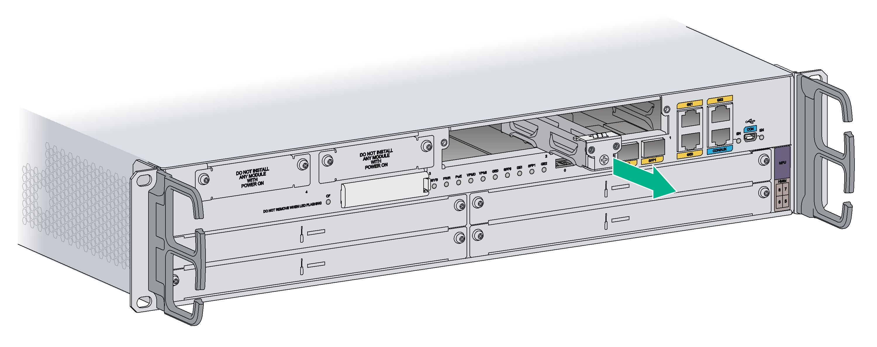
To replace a SIC:
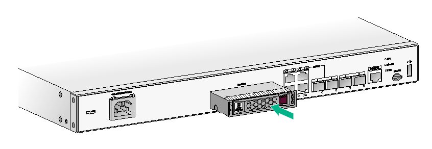
1. Completely loosen the captive screws of the SIC.
2. Gently pull the SIC out along the slide rails.
3. Install a new SIC. For the installation procedure, see "Installing an interface module."
If you do not install a SIC, install a filler panel and tighten the screws.
Figure3-23 Pulling a SIC out
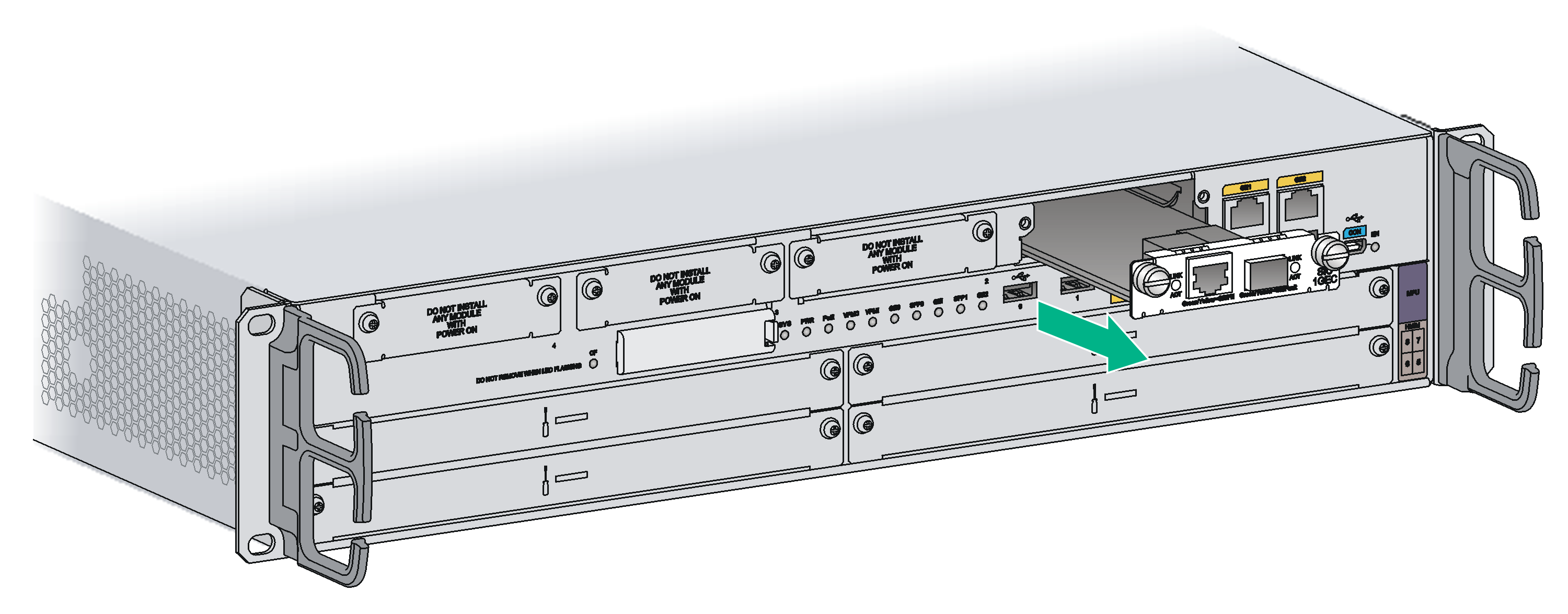
Figure3-24 Installing a filler panel
Replacing a DSIC
|
|
CAUTION: DSIC interface modules are not hot swappable. Make sure the router is powered off before installing a DSIC. |
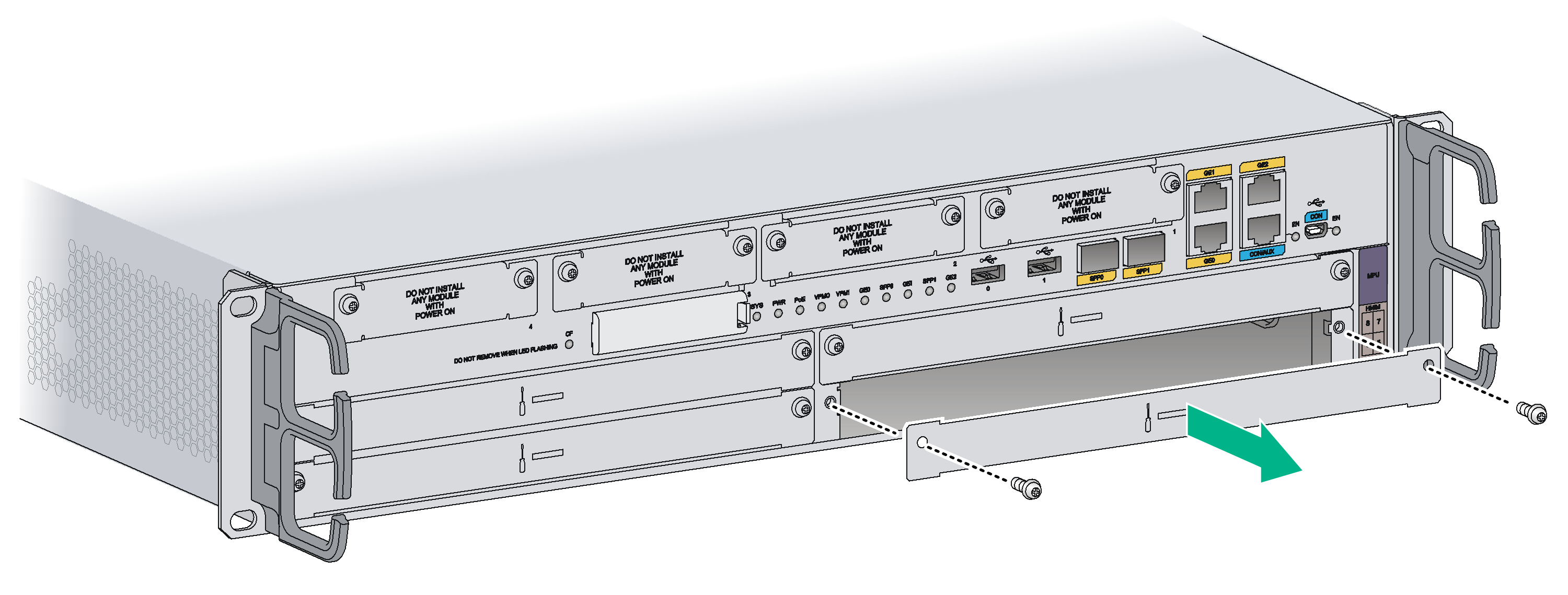
To replace a DSIC:
1. Completely loosen the captive screws of the DSIC.
2. Gently pull the DSIC out along the slide rails.
If you need to install SIC or DSIC interface modules, see "Installing an interface module" for the installation procedure.
To install filler panels, proceed to steps 3 and 4.
3. Gently push the slot divider into the DSIC slot along the slide rails and tighten the screws.
4. Install filler panels and tighten the screws.
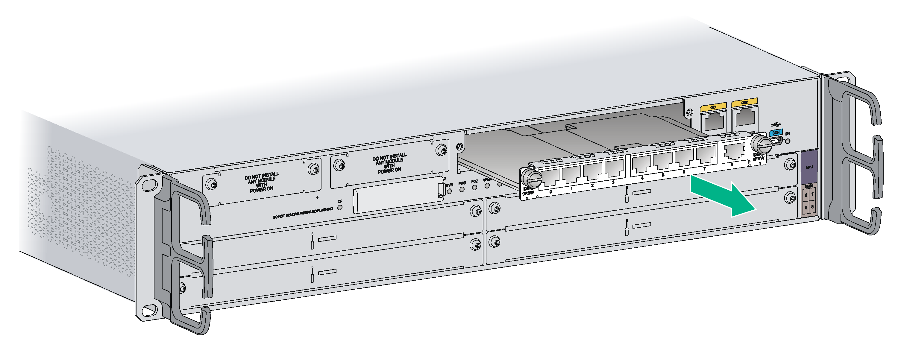
Figure3-26 Installing a slot divider
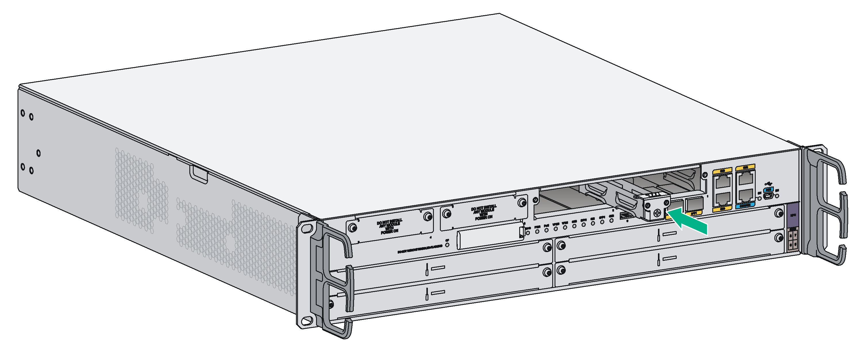
Figure3-27 Installing filler panels
Replacing an HMIM
|
|
IMPORTANT: To hot-remove an HMIM, you must first execute the remove command or press the remove button on the HMIM. For information about how to use the remove command, see the related command reference. The remove button use method varies by HMIM interface module. For the specific use method, see H3C MSR Router Series Interface Module Guide. An HMIM interface module with a remove button supports also using the remove command. You cannot use the remove command and remove button simultaneously when hot swapping a HMIM module. If the two methods are used simultaneously, the HMIM interface module might fail to operate correctly. |
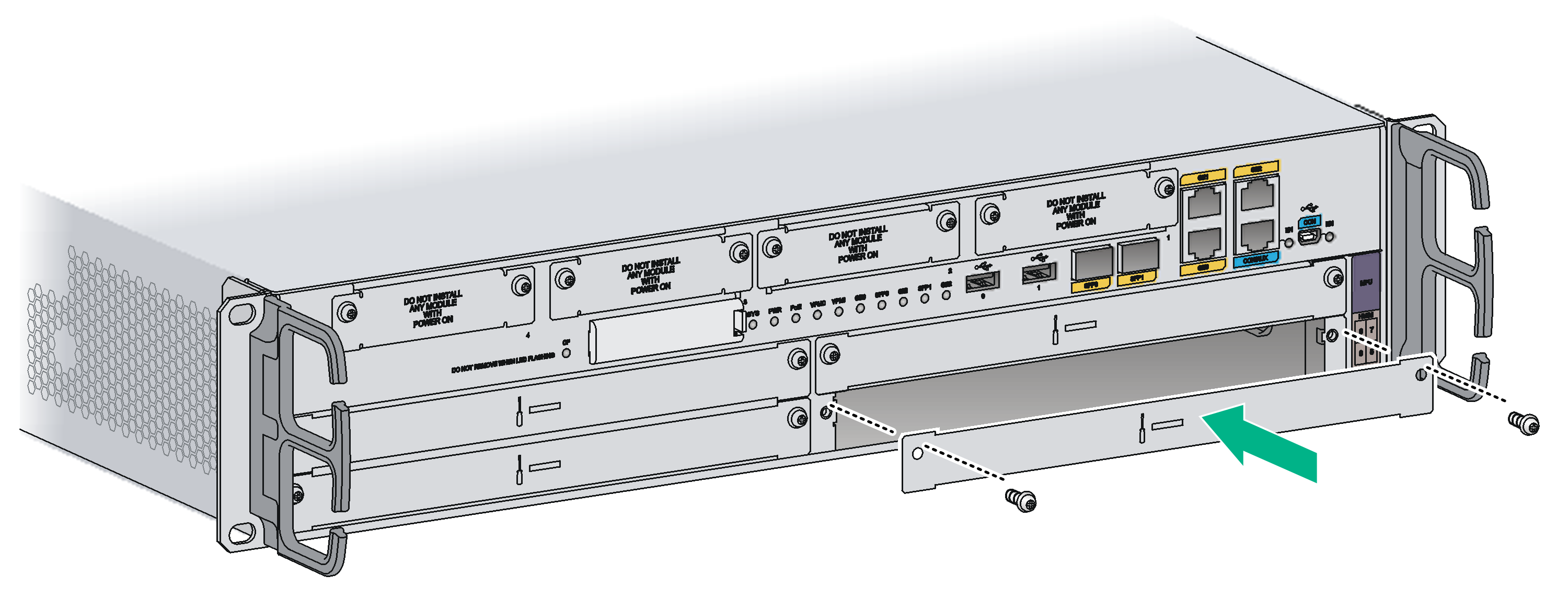
To replace an HMIM:
1. Completely loosen the captive screws of the HMIM.
2. Gently pull the HMIM out of the slot along the slide rails.
3. Install a new HMIM. For the installation procedure, see "Installing an interface module."
If you do not install a new HMIM, install a filler panel and tighten the screws.
Figure3-28 Pulling the HMIM out of the slot
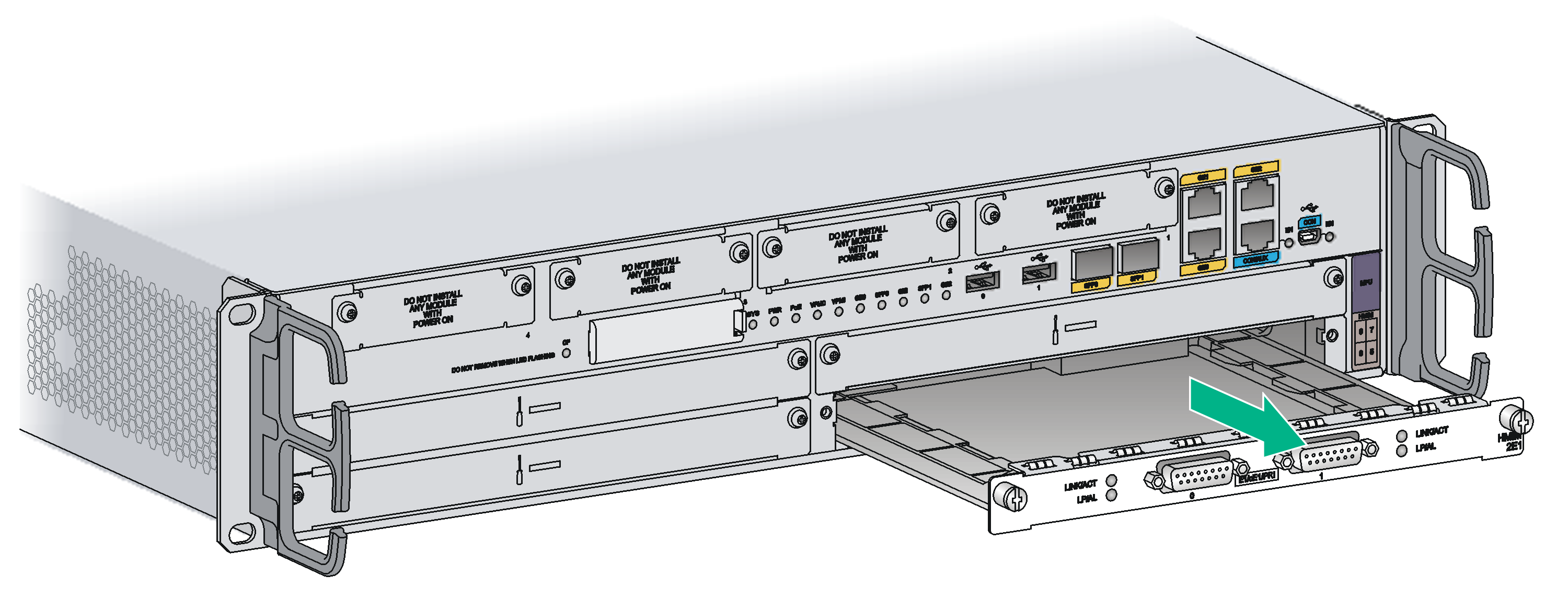
Figure3-29 Installing a filler panel
Replacing a MIM
|
|
WARNING! You can replace a MIM when the router is operating. To hot-remove a MIM, you must execute the remove command. |
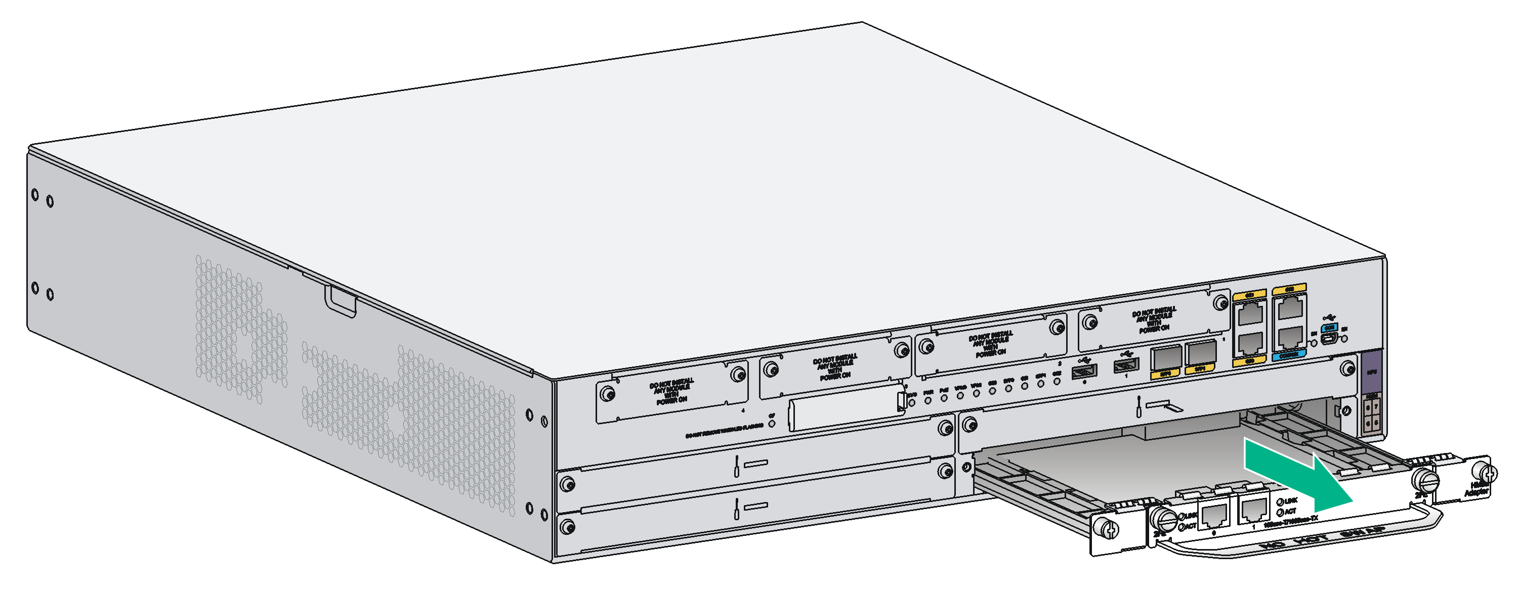
To replace a MIM:
1. Completely loosen the captive screws of the HMIM adapter.
2. Gently pull the MIM and the HMIM adapter out of the slot along the slide rails.
Figure3-30 Removing a MIM and the HMIM adapter
3. Completely loosen the captive screws of the MIM, remove the screws that secure the MIM to the HMIM adapter, and pull the MIM out of the HMIM adapter along the slide rails.
Keep the removed MIM for future use.
4. Install a new MIM. For the installation procedure, see "Installing an interface module."
If you do not install a new MIM in the slot, install a filler panel and tighten the screws.
Figure3-31 Removing a MIM
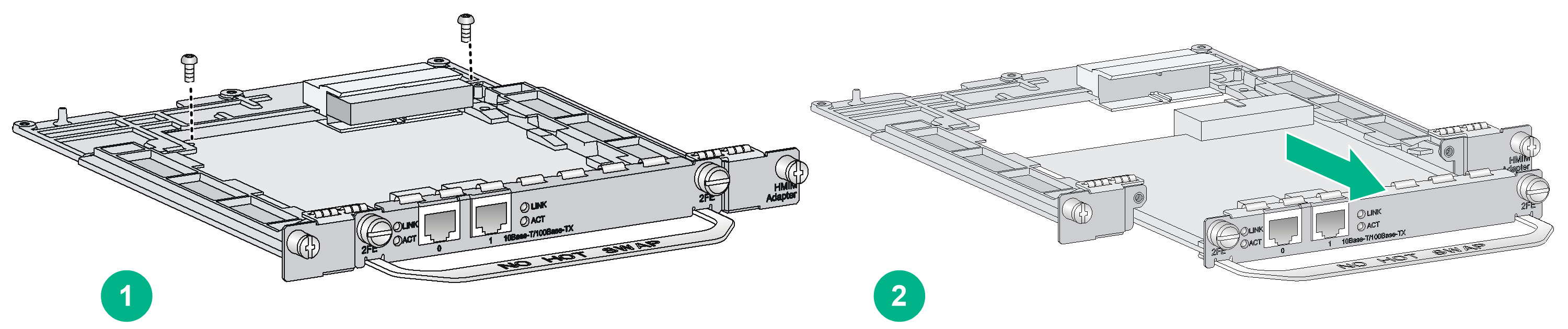
Figure3-32 Installing a filler panel

4 Troubleshooting
|
|
IMPORTANT: · The barcode on the router chassis contains product information that must be provided to local sales agent when you return a faulty router for service. · Keep the tamper-proof seal on a mounting screw on the chassis cover intact, and if you want to open the chassis, contact H3C for permission. Otherwise, H3C shall not be liable for any consequence. |
Power supply system failure
Symptom
The router cannot be powered on. The power LED is off.
Solution
To resolve the issue:
1. Turn off the power switch of the power source.
2. Verify that the power cord of the router is correctly connected to the router and the power source.
3. Verify that the power source is operating correctly.
4. Verify that the power cord is in good condition.
5. If the issue persists, contact H3C Support.
Fan failures
Symptom
After the router starts up, the following error message appears on the configuration terminal:
%Jun 22 16:11:37:485 2018 H3C DEV/4/FAN FAILED:
Fan 1 failed.
Solution
1. Verify that the fans are correctly installed.
2. Verify that no obstacle enters the chassis and blocks the fans.
3. Verify that no fan stops rotating. If a fan stops rotating, replace the fan.
4. If the issue persists, contact H3C Support.
Configuration terminal issues
If the configuration environment setup is correct, the configuration terminal displays boot information when the router is powered on. If the setup is incorrect, the configuration terminal displays nothing or garbled text.
No terminal display
Symptom
The configuration terminal displays nothing when the router is powered on.
Solution
To resolve the issue:
1. Verify that the power supply system is operating correctly.
2. Verify that the console cable is correctly connected to the console port.
3. Verify that the console cable is connected to the serial port that is configured for the configuration terminal.
4. Verify that the configuration terminal parameters are configured as follows:
¡ Baud rate—9600
¡ Data bits—8
¡ Parity—none
¡ Stop bits—1
¡ Flow control—none
¡ Terminal emulation—VT100
5. Verify that the console cable is in good condition.
6. If the issue persists, contact H3C Support.
Garbled terminal display
Symptom
The configuration terminal displays garbled characters when the router is powered on.
Solution
Verify that the Data bits field is set to 8 for the configuration terminal. If the Data bits field is set to 5 or 6, the configuration terminal displays garbled characters.
No response from the serial port
Symptom
No boot information is displayed on the configuration terminal when the router starts up or restarts up.
Solution
Verify that the serial cable is in good condition and the serial port settings are correct.
Interface module, cable, and connection failure
Symptom
After an interface module is installed and the router is powered on, the LEDs on the interface module panel indicate that the interface module is operating incorrectly.
Solution
To resolve the issue:
1. Verify that the interface module makes good contact with the rear panel of the router slot.
2. Verify that the router supports the interface module.
3. Verify that the interface module is installed in the specified router slot.
4. Verify that a correct cable is used.
5. Verify that the cable is correctly connected.
6. If the issue persists, contact H3C Support.
Restoring the factory settings
Only the MSR3600-28/MSR3600-51 router provides a RESET button.
Scenario 1
Symptom
When you replace the router, the router password is lost. As a result, you cannot log in to the router and do not know the router configuration.
Solution
Because the router is replaced, you do not need to save the configuration of the router. In this case, you can press the RESET button for more than 4 seconds to reboot the router and restore the factory settings. Then, you can use the username and password shipped with the router to log in to the router.
When the router configuration must be saved and you have a console cable, you can log in to the router through the BootWare menu.
Scenario 2
Symptom
After the configuration is modified, the network connectivity is lost. When you check the configuration, the configuration is very complicated and it is hard to locate the errors. In this case, you must configure the router again.
Solution
If you have not saved any configuration, you can reboot the router by pressing the RESET button for a short time or power off the router.
If you have saved some configurations, you can use the CLI to delete the configuration file or press the RESET button to restore the factory settings.
Scenario 3
Symptom
The router crashes.
Solution
Press the RESET button for a short time to reboot the router.
Reset button usage guidelines
You can use the button to reboot the system or restore the factory settings.
· Press the RESET button for a short time to reboot the router.
· Press the RESET button for more than 4 seconds to reboot the router and restore the factory settings.
