- Table of Contents
- Related Documents
-
| Title | Size | Download |
|---|---|---|
| 01-Hardware Information and Specifications | 2.07 MB |
1 Product models and technical specifications
10/100/1000BASE-T autosensing Ethernet port
10/100/1000BASE-T autosensing Ethernet port LEDs
1 Product models and technical specifications
Product models
This document is applicable to the following Ethernet switches.
|
Product series |
Product model |
Product code (PID) |
|
S1850-X switch series |
S1850-28X |
LS-1850-28X |
|
S1850-52X |
LS-1850-52X |
|
|
S1850-28X-PWR |
LS-1850-28X-PWR |
|
|
S1850-52X-PWR |
LS-1850-52X-PWR |
|
|
S1850V2-X switch series |
S1850V2-28X |
LS-1850V2-28X LS-1850V2-28X-GL |
|
S1850V2-52X |
LS-1850V2-52X LS-1850V2-52X-GL |
|
|
S1850V2-28X-HPWR |
LS-1850V2-28X-HPWR LS-1850V2-28X-HPWR-GL |
|
|
S1850V2-52X-PWR |
LS-1850V2-52X-PWR LS-1850V2-52X-PWR-GL |
|
|
S1850V2-EI switch series |
S1850V2-52P-EI |
LS-1850V2-52P-EI LS-1850V2-52P-EI-GL |
|
S1850V2-28P-EI |
LS-1850V2-28P-EI LS-1850V2-28P-EI-GL |
|
|
S1850V2-28P-HPWR-EI |
LS-1850V2-28P-HPWR-EI LS-1850V2-28P-HPWR-EI-GL |
|
|
S1850V2-9P-EI |
LS-1850V2-9P-EI |
|
|
S1850V2-10P-EI |
LS-1850V2-10P-EI LS-1850V2-10P-EI-GL |
|
|
S1850V2-10P-PWR-EI |
LS-1850V2-10P-PWR-EI |
|
|
S1850V2-10P-HPWR-EI |
LS-1850V2-10P-HPWR-EI-GL |
|
|
NOTE: Switches of the same model but different PIDs might differ in hardware and software features. You can view the PID of a switch on the label located on its rear panel or top panel. |
Technical specifications
S1850-X switch series
Table1-1 Technical specifications of S1850-X non-PoE switch models
|
Item |
S1850-28X |
S1850-52X |
|
Dimensions (H × W × D) |
43.6 × 440 × 160 mm (1.72 × 17.32 × 6.30 in) |
43.6 × 440 × 230 mm (1.72 × 17.32 × 9.06 in) |
|
Weight |
≤ 2.5 kg (5.51 lb) |
≤ 3.5 kg (7.72 lb) |
|
Console port |
· 1 × serial console port · 1 × micro USB console port If you connect each of the console ports to a configuration terminal, only the micro USB console port takes effect. |
|
|
10/100/1000BASE-T autosensing Ethernet port |
24 |
48 |
|
SFP port |
2 |
2 |
|
SFP+ port |
2 |
2 |
|
Input voltage |
· Rated voltage range: 100 VAC to 240 VAC @ 50 or 60 Hz · Max voltage range: 90 VAC to 264 VAC @ 47 to 63 Hz |
|
|
Power consumption (static) |
9 W |
19 W |
|
Power consumption (fully loaded) |
24 W |
44 W |
|
Chassis leakage current compliance |
UL 62368-1/EN 62368-1/IEC 62368-1/UL 60950-1/IEC 60950-1/GB4943.1 |
|
|
Melting current of power supply fuse |
2 A/250 V |
3.15 A/250 V |
|
Cooling system |
The device uses fixed fan trays. It draws cool air from the chassis left side, right side, and port side and exhausts heated air from the power supply side. |
The device uses fixed fan trays. It draws cool air from the chassis left side and right side and exhausts heated air from the power supply side. |
|
Operating temperature |
–5°C to +45°C (23°F to 113°F) |
|
|
Operating humidity |
5% to 95%, noncondensing |
|
|
Fire resistance compliance |
UL 62368-1/EN 62368-1/IEC 62368-1/UL 60950-1/IEC 60950-1/GB4943.1 |
|
Table1-2 Technical specifications of S1850-X PoE switch models
|
Item |
S1850-28X-PWR |
S1850-52X-PWR |
|
Dimensions (H × W × D) |
43.6 × 440 × 260 mm (1.72 × 17.32 × 10.24 in) |
43.6 × 440 × 400 mm (1.72 × 17.32 × 15.75 in) |
|
Weight |
≤ 4 kg (8.82 lb) |
≤ 6 kg (13.23 lb) |
|
Console port |
· 1 × serial console port · 1 × micro USB console port If you connect each of the console ports to a configuration terminal, only the micro USB console port takes effect. |
|
|
10/100/1000BASE-T autosensing Ethernet port |
24 |
48 |
|
SFP port |
2 |
2 |
|
SFP+ port |
2 |
2 |
|
Input voltage |
· AC ¡ Rated voltage range: 100 VAC to 240 VAC @ 50 or 60 Hz ¡ Max voltage range: 90 VAC to 264 VAC @ 47 to 63 Hz · DC (supported only on the S1850-52X-PWR switch) ¡ Rated voltage range: –54 to –57 VDC ¡ Max voltage range: Single DC input: –44 to –60 VDC AC+DC input: –54 to –57 VDC You can only use an H3C RPS1600-A power supply to supply DC power to the device. |
|
|
Max PoE power per port |
30 W |
30 W |
|
Total PoE power |
185 W |
AC: 370 W DC: 740 W |
|
Static power consumption |
15 W |
AC: 32 W DC: 26 W |
|
Max power consumption (including PoE power output ) |
219 W |
AC: 473 W DC: 820 W |
|
Chassis leakage current compliance |
UL 62368-1/EN 62368-1/IEC 62368-1/UL 60950-1/IEC 60950-1/GB4943.1 |
|
|
Melting current of power supply fuse |
10 A/250 V |
15 A/250 V |
|
Cooling system |
The device uses fixed fan trays. It draws cool air from the chassis left side and port side and exhausts heated air from the right side. |
The device uses fixed fan trays. It draws cool air from the chassis left side and exhausts heated air from the chassis right side. |
|
Operating temperature |
–5°C to +45°C (23°F to 113°F) |
|
|
Operating humidity |
5% to 95%, noncondensing |
|
|
Fire resistance compliance |
UL 62368-1/EN 62368-1/IEC 62368-1/UL 60950-1/IEC 60950-1/GB4943.1 |
|
S1850V2-X switch series
Table1-3 Technical specifications of S1850V2-X non-PoE switch models
|
Item |
S1850V2-28X |
S1850V2-52X |
|
Dimensions (H × W × D) |
43.6 × 440 × 160 mm (1.72 × 17.32 × 6.30 in) |
43.6 × 440 × 230 mm (1.72 × 17.32 × 9.06 in) |
|
Weight |
≤ 2.5 kg (5.5115 lb) |
≤ 3.5 kg (7.716 lb) |
|
Console port |
1 × serial console port |
|
|
10/100/1000BASE-T autosensing Ethernet port |
24 |
48 |
|
SFP+ port |
4 |
4 |
|
Input voltage |
· Rated voltage range: 100 VAC to 240 VAC @ 50 or 60 Hz · Max voltage range: 90 VAC to 264 VAC @ 47 to 63 Hz |
|
|
Power consumption (static) |
10 W |
19 W |
|
Power consumption (fully loaded) |
24 W |
44 W |
|
Chassis leakage current compliance |
UL 62368-1/EN 62368-1/IEC 62368-1/UL 60950-1/IEC 60950-1/GB4943.1 |
|
|
Melting current of power supply fuse |
2 A/250 V |
3.15 A/250 V |
|
Cooling system |
Natural cooling without fan trays |
The device uses fixed fan trays. It draws cool air from the chassis left side and right side and exhausts heated air from the power supply side. |
|
Operating temperature |
–5°C to +45°C (23°F to 113°F) |
|
|
Operating humidity |
5% to 95%, noncondensing |
|
|
Fire resistance compliance |
UL 62368-1/EN 62368-1/IEC 62368-1/UL 60950-1/IEC 60950-1/GB4943.1 |
|
Table1-4 Technical specifications of S1850V2-X PoE switch models
|
Item |
S1850V2-28X-HPWR |
S1850V2-52X-PWR |
|
Dimensions (H × W × D) |
43.6 × 440 × 260 mm (1.72 × 17.32 × 10.24 in) |
43.6 × 440 × 400 mm (1.72 × 17.32 × 15.75 in) |
|
Weight |
≤ 4.5 kg (9.92 lb) |
≤ 6 kg (13.23 lb) |
|
Console port |
1 × serial console port |
|
|
10/100/1000BASE-T autosensing Ethernet port |
24 |
48 |
|
SFP+ port |
4 |
4 |
|
Input voltage |
· Rated voltage range: 100 VAC to 240 VAC @ 50 or 60 Hz · Max voltage range: 90 VAC to 264 VAC @ 47 to 63 Hz |
|
|
Max PoE power per port |
30 W |
30 W |
|
Total PoE power |
370 W |
370 W |
|
Static power consumption |
19 W |
36 W |
|
Max power consumption (including PoE power output ) |
448 W |
467 W |
|
Chassis leakage current compliance |
UL 62368-1/EN 62368-1/IEC 62368-1/UL 60950-1/IEC 60950-1/GB4943.1 |
|
|
Melting current of power supply fuse |
10 A/250 V |
15 A/250 V |
|
Cooling system |
The device uses fixed fan trays. It draws cool air from the chassis left side and port side and exhausts heated air from the chassis right side. |
The device uses fixed fan trays. It draws cool air from the chassis left side and exhausts heated air from the chassis right side. |
|
Operating temperature |
–5°C to +45°C (23°F to 113°F) |
|
|
Operating humidity |
5% to 95%, noncondensing |
|
|
Fire resistance compliance |
UL 62368-1/EN 62368-1/IEC 62368-1/UL 60950-1/IEC 60950-1/GB4943.1 |
|
S1850V2-EI switch series
Table1-5 Technical specifications of S1850V2-EI non-PoE switch models (1)
|
Item |
S1850V2-10P-EI |
S1850V2-9P-EI |
|
Dimensions (H × W × D) |
43.6 × 266 × 161 mm (1.72 × 10.47 × 6.34 in) |
43.6 × 266 × 161 mm (1.72 × 10.47 × 6.34 in) |
|
Weight |
≤ 1.5 kg (3.31 lb) |
≤ 1.5 kg (3.31 lb) |
|
Console port |
1 × serial console port |
1 × serial console port |
|
10/100/1000BASE-T autosensing Ethernet port |
8 |
8 |
|
SFP port |
2 |
1 |
|
Input voltage |
· Rated voltage range: 100 VAC to 240 VAC @ 50 or 60 Hz · Max voltage range: 90 VAC to 264 VAC @ 47 to 63 Hz |
|
|
Power consumption (static) |
8 W |
8 W |
|
Power consumption (fully loaded) |
14 W |
14 W |
|
Chassis leakage current compliance |
UL 62368-1/EN 62368-1/IEC 62368-1/UL 60950-1/IEC 60950-1/GB4943.1 |
|
|
Melting current of power supply fuse |
2 A/250 V |
2 A/250 V |
|
Cooling system |
Natural cooling without fan trays |
Natural cooling without fan trays |
|
Operating temperature |
–5°C to +45°C (23°F to 113°F) |
|
|
Operating humidity |
5% to 95%, noncondensing |
|
|
Fire resistance compliance |
UL 62368-1/EN 62368-1/IEC 62368-1/UL 60950-1/IEC 60950-1/GB4943.1 |
|
Table1-6 Technical specifications of S1850V2-EI non-PoE switch models (2)
|
Item |
S1850V2-28P-EI |
S1850V2-52P-EI |
|
Dimensions (H × W × D) |
43.6 × 440 × 160 mm (1.72 × 17.32 × 6.30 in) |
43.6 × 440 × 230 mm (1.72 × 17.32 × 9.06 in) |
|
Weight |
≤ 2.5 kg (5.51 lb) |
≤ 3.5 kg (7.72 lb) |
|
Console port |
1 × serial console port |
1 × serial console port |
|
10/100/1000BASE-T autosensing Ethernet port |
24 |
48 |
|
SFP port |
4 |
4 |
|
Input voltage |
· Rated voltage range: 100 VAC to 240 VAC @ 50 or 60 Hz · Max voltage range: 90 VAC to 264 VAC @ 47 to 63 Hz |
|
|
Power consumption (static) |
9 W |
18 W |
|
Power consumption (fully loaded) |
23 W |
41 W |
|
Chassis leakage current compliance |
UL 62368-1/EN 62368-1/IEC 62368-1/UL 60950-1/IEC 60950-1/GB4943.1 |
|
|
Melting current of power supply fuse |
2 A/250 V |
3.15 A/250 V |
|
Cooling system |
Natural cooling without fan trays |
Using fixed fan trays to draw ambient air in from the left side and right side and exhaust heated air from the power supply side. |
|
Operating temperature |
–5°C to +45°C (23°F to 113°F) |
|
|
Operating humidity |
5% to 95%, noncondensing |
|
|
Fire resistance compliance |
UL 62368-1/EN 62368-1/IEC 62368-1/UL 60950-1/IEC 60950-1/GB4943.1 |
|
Table1-7 Technical specifications of S1850V2-EI PoE switch models
|
Item |
S1850V2-10P-HPWR-EI |
S1850V2-28P-HPWR-EI |
S1850V2-10P-PWR-EI |
|
Dimensions (H × W × D) |
43.6 × 330 × 230 mm (1.72 × 12.99 × 9.06 in) |
43.6 × 440 × 260 mm (1.72 × 17.32 ×10.24 in) |
43.6 × 330 × 230 mm (1.72 × 12.99 × 9.06 in) |
|
Weight |
≤ 3 kg (6.61 lb) |
≤ 4.5 kg (9.92 lb) |
≤ 3 kg (6.61 lb) |
|
Console port |
1 × serial console port |
1 × serial console port |
1 × serial console port |
|
10/100/1000BASE-T autosensing Ethernet port |
8 |
24 |
8 |
|
SFP port |
2 |
4 |
2 |
|
Input voltage |
· Rated voltage range: 100 VAC to 240 VAC @ 50 or 60 Hz · Max voltage range: 90 VAC to 264 VAC @ 47 to 63 Hz |
||
|
Maximum PoE power per port |
30 W |
30 W |
30 W |
|
Total PoE power |
125 W |
370 W |
65 W |
|
Power consumption (static) |
10 W |
19 W |
8 W |
|
Power consumption (fully loaded, including PoE output) |
155 W |
448 W |
90 W |
|
Chassis leakage current compliance |
UL 62368-1/EN 62368-1/IEC 62368-1/UL 60950-1/IEC 60950-1/GB4943.1 |
||
|
Melting current of power supply fuse |
6.3 A/250 V |
10 A/250 V |
6.3 A/250 V |
|
Cooling system |
Natural cooling without fan trays |
The device uses fixed fan trays. It draws cool air in from the chassis left side and port side and exhaust heated air from the chassis right side. |
Natural cooling without fan trays |
|
Operating temperature |
–5°C to +45°C (23°F to 113°F) NOTE: The maximum allowed temperature is decreased by 0.33°C (32.59°F) for every increase of 100 m (328.08 ft) above 0 m (0 ft) in altitude. |
||
|
Operating humidity |
5% to 95%, noncondensing |
||
|
Fire resistance compliance |
UL 62368-1/EN 62368-1/IEC 62368-1/UL 60950-1/IEC 60950-1/GB4943.1 |
||
2 Chassis views
S1850-X switch series
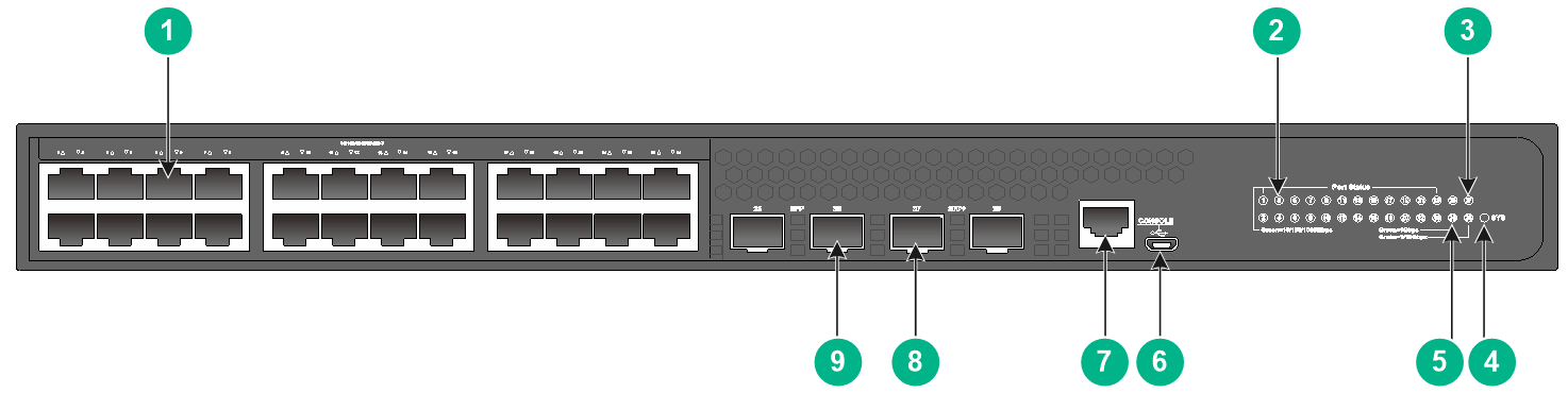
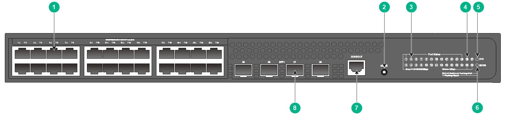
S1850-28X
Figure2-1 Front panel
|
(1) 10/100/1000BASE-T autosensing Ethernet port |
|
|
(2) 10/100/1000BASE-T autosensing Ethernet port LED |
|
|
(3) SFP+ port LED |
(4) System status LED (SYS) |
|
(5) SFP port LED |
(6) Micro USB console port |
|
(7) Console port (CONSOLE) |
(8) SFP+ port |
|
(9) SFP port |
|
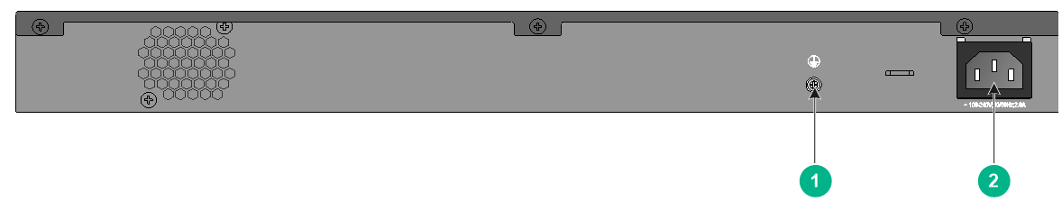
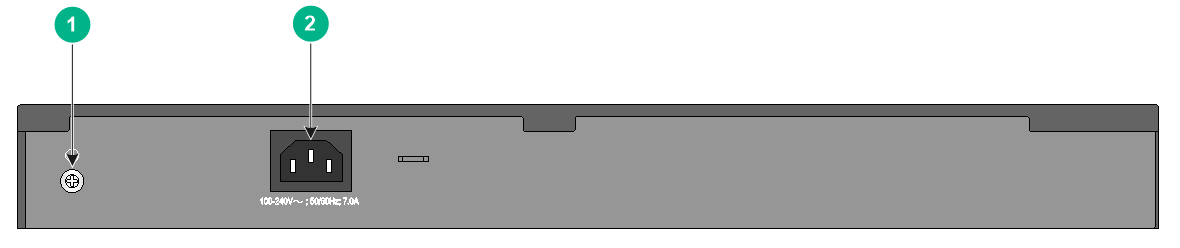
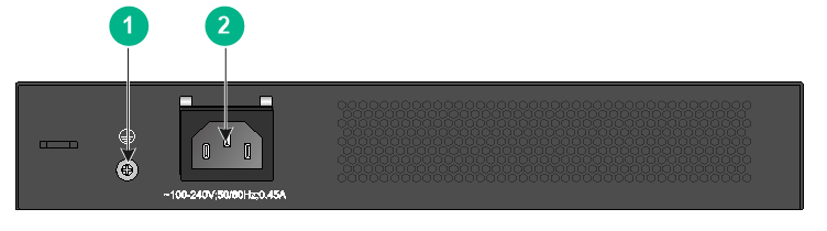
Figure2-2 Rear panel

|
(1) Grounding screw |
(2) AC-input power receptacle |
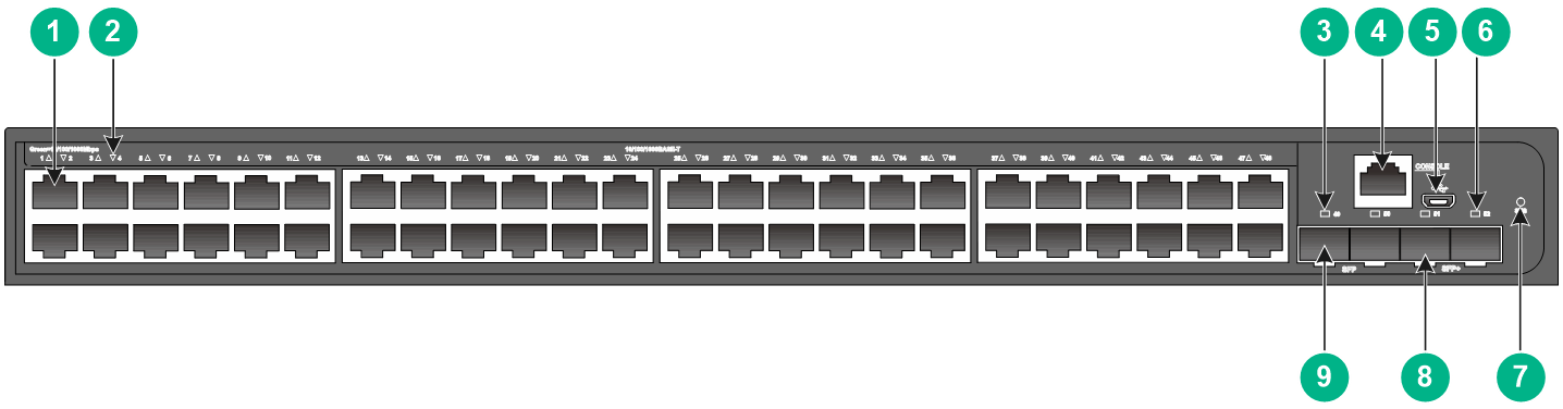
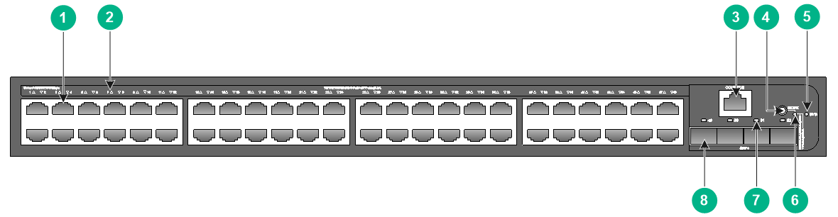
S1850-52X
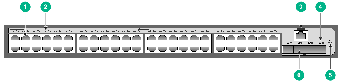
Figure2-3 Front panel
|
(1) 10/100/1000BASE-T autosensing Ethernet port |
|
|
(2) 10/100/1000BASE-T autosensing Ethernet port LED |
|
|
(3) SFP port LED |
(4) Console port (CONSOLE) |
|
(5) Micro USB console port |
(6) SFP+ port LED |
|
(7) System status LED (SYS) |
(8) SFP+ port |
|
(9) SFP port |
|
Figure2-4 Rear panel
|
(1) Grounding screw |
(2) AC-input power receptacle |
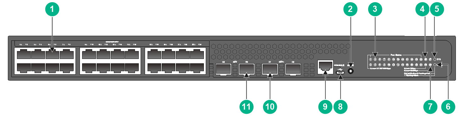
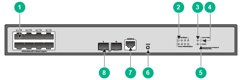
S1850-28X-PWR
Figure2-5 Front panel
|
(1) 10/100/1000BASE-T autosensing Ethernet port |
(2) Port LED mode switching button |
|
(3) 10/100/1000BASE-T autosensing Ethernet port LED |
(4) SFP port LED |
|
(5) System status LED (SYS) |
(6) Mode LED (MODE) |
|
(7) SFP+ port LED |
(8) Micro USB console port |
|
(9) Console port (CONSOLE) |
(10) SFP+ port |
|
(11) SFP port |
|
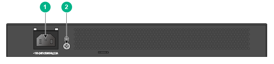
Figure2-6 Rear panel
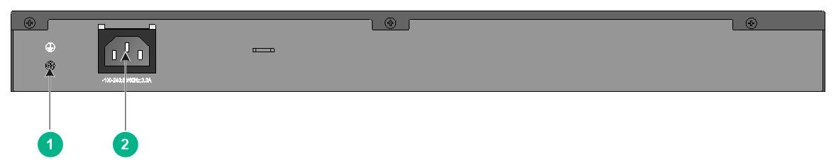
|
(1) Grounding screw |
(2) AC-input power receptacle |
S1850-52X-PWR
Figure2-7 Front panel
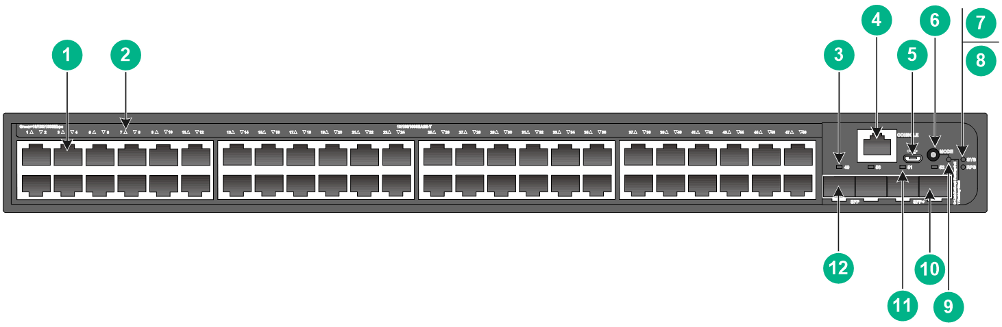
|
(1) 10/100/1000BASE-T autosensing Ethernet port |
|
|
(2) 10/100/1000BASE-T autosensing Ethernet port LED |
|
|
(3) SFP port LED |
(4) Console port (CONSOLE) |
|
(5) Micro USB console port |
(6) Port LED mode switching button |
|
(7) System status LED (SYS) |
(8) RPS power supply status LED (RPS) |
|
(9) Mode LED (MODE) |
(10) SFP+ port |
|
(11) SFP+ port LED |
(12) SFP port |
Figure2-8 Rear panel
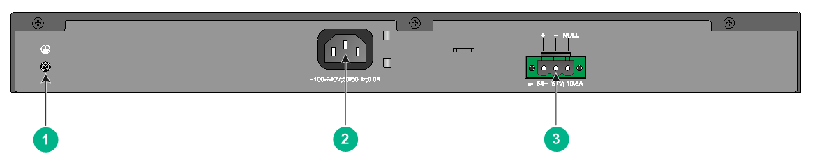
|
(1) Grounding screw |
(2) AC-input power receptacle |
|
(3) DC-input power receptacle |
|
S1850V2-X switch series
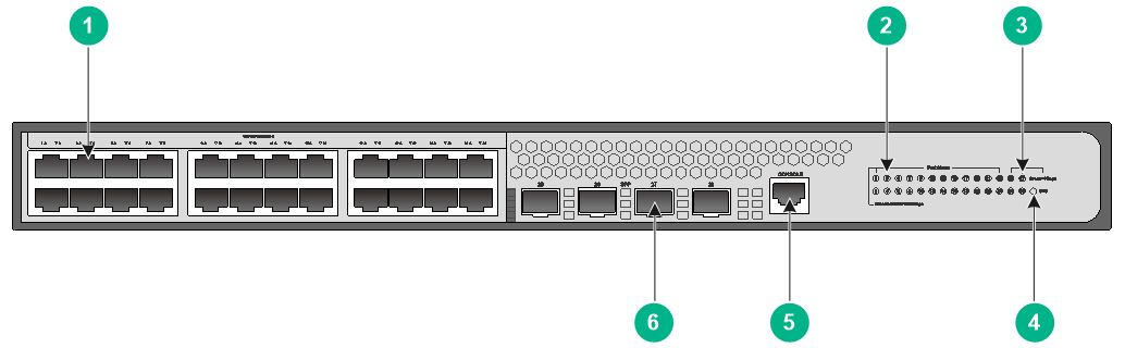
S1850V2-28X
Figure2-9 Front panel

|
(1) 10/100/1000BASE-T autosensing Ethernet port |
|
|
(2) 10/100/1000BASE-T autosensing Ethernet port LED |
|
|
(3) SFP+ port LED |
(4) System status LED (SYS) |
|
(5) Console port (CONSOLE) |
(6) SFP+ port |
Figure2-10 Rear panel
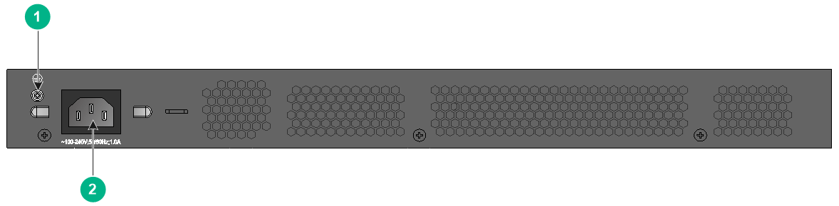
|
(1) Grounding screw |
(2) AC-input power receptacle |
S1850V2-52X
Figure2-11 Front panel

|
(1) 10/100/1000BASE-T autosensing Ethernet port |
|
|
(2) 10/100/1000BASE-T autosensing Ethernet port LED |
|
|
(3) Console port (CONSOLE) |
(4) SFP+ port LED |
|
(5) System status LED (SYS) |
(6) SFP+ port |
Figure2-12 Rear panel

|
(1) Grounding screw |
(2) AC-input power receptacle |
S1850V2-28X-HPWR
Figure2-13 Front panel
|
(1) 10/100/1000BASE-T autosensing Ethernet port |
(2) Port LED mode switching button |
|
(3) 10/100/1000BASE-T autosensing Ethernet port LED |
(4) SFP+ port LED |
|
(5) System status LED (SYS) |
(6) Mode LED (MODE) |
|
(7) Console port (CONSOLE) |
(8) SFP+ port |
Figure2-14 Rear panel

|
(1) Grounding screw |
(2) AC-input power receptacle |
S1850V2-52X-PWR
Figure2-15 Front panel
|
(1) 10/100/1000BASE-T autosensing Ethernet port |
|
|
(2) 10/100/1000BASE-T autosensing Ethernet port LED |
|
|
(3) Console port (CONSOLE) |
(4) Port LED mode switching button |
|
(5) System status LED (SYS) |
(6) Mode LED (MODE) |
|
(7) SFP+ port LED |
(8) SFP+ port |
Figure2-16 Rear panel
|
(1) Grounding screw |
(2) AC-input power receptacle |
S1850V2-EI switch series
S1850V2-28P-EI
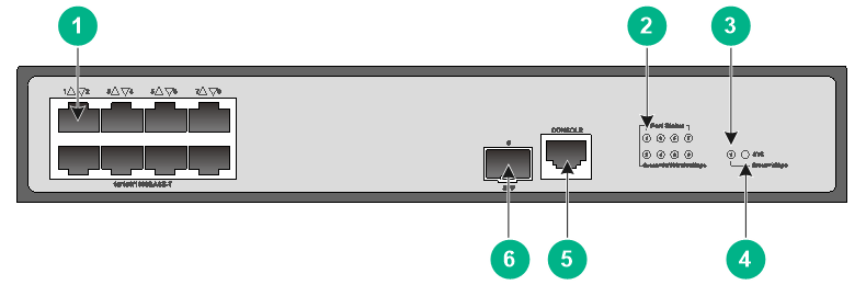
Figure2-17 Front panel
|
(1) 10/100/1000BASE-T autosensing Ethernet port |
|
|
(2) 10/100/1000BASE-T autosensing Ethernet port LED |
|
|
(3) SFP port LED |
(4) System status LED (SYS) |
|
(5) Console port (CONSOLE) |
(6) SFP port |
Figure2-18 Rear panel

|
(1) Grounding screw |
(2) AC-input power receptacle |
S1850V2-52P-EI
Figure2-19 Front panel
|
(1) 10/100/1000BASE-T autosensing Ethernet port |
|
|
(2) 10/100/1000BASE-T autosensing Ethernet port LED |
|
|
(3) Console port (CONSOLE) |
(4) SFP port LED |
|
(5) System status LED (SYS) |
(6) SFP port |
Figure2-20 Rear panel

|
(1) Grounding screw |
(2) AC-input power receptacle |
S1850V2-9P-EI
Figure2-21 Front panel
|
(1) 10/100/1000BASE-T autosensing Ethernet port |
|
|
(2) 10/100/1000BASE-T autosensing Ethernet port LED |
|
|
(3) SFP port LED |
(4) System status LED (SYS) |
|
(5) Console port (CONSOLE) |
(6) SFP port |
Figure2-22 Rear panel

|
(1) Grounding screw |
(2) AC-input power receptacle |
S1850V2-10P-EI
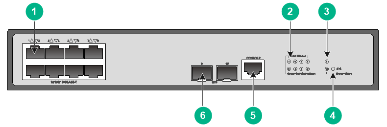
Figure2-23 Front panel
|
(1) 10/100/1000BASE-T autosensing Ethernet port |
|
|
(2) 10/100/1000BASE-T autosensing Ethernet port LED |
|
|
(3) SFP port LED |
(4) System status LED (SYS) |
|
(5) Console port (CONSOLE) |
(6) SFP port |
Figure2-24 Rear panel
|
(1) Grounding screw |
(2) AC-input power receptacle |
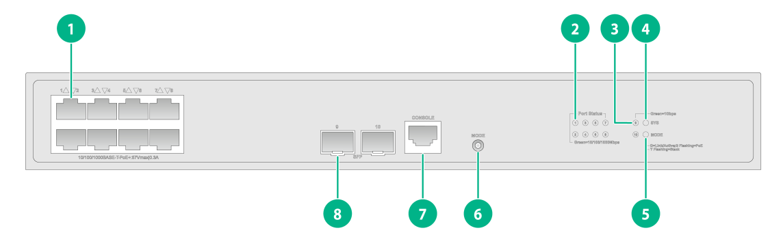
S1850V2-10P-HPWR-EI
Figure2-25 Front panel
|
(1) 10/100/1000BASE-T autosensing Ethernet port |
|
|
(2) 10/100/1000BASE-T autosensing Ethernet port LED |
|
|
(3) SFP port LED |
(4) System status LED (SYS) |
|
(5) Mode LED (MODE) |
(6) Port LED mode switching button |
|
(7) Console port (CONSOLE) |
(8) SFP port |
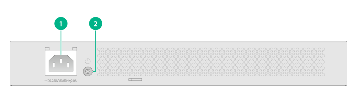
Figure2-26 Rear panel
|
(1) AC-input power receptacle |
(2) Grounding screw |
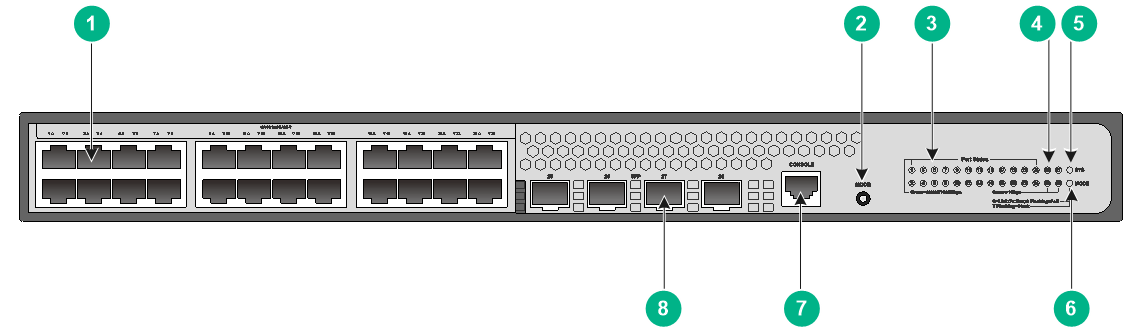
S1850V2-28P-HPWR-EI
Figure2-27 Front panel
|
(1) 10/100/1000BASE-T autosensing Ethernet port |
(2) Port LED mode switching button |
|
(3) 10/100/1000BASE-T autosensing Ethernet port LED |
(4) SFP port LED |
|
(5) System status LED (SYS) |
(6) Mode LED (MODE) |
|
(7) Console port (CONSOLE) |
(8) SFP port |
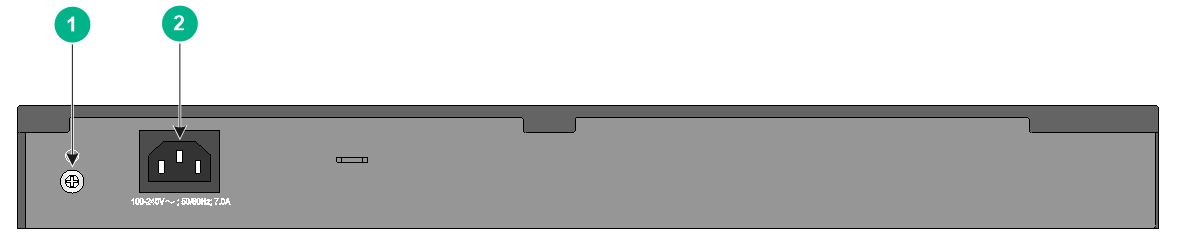
Figure2-28 Rear panel
|
(1) Grounding screw |
(2) AC-input power receptacle |
S1850V2-10P-PWR-EI
Figure2-29 Front panel
|
(1) 10/100/1000BASE-T autosensing Ethernet port |
|
|
(2) 10/100/1000BASE-T autosensing Ethernet port LED |
|
|
(3) SFP port LED |
(4) System status LED (SYS) |
|
(5) Mode LED (MODE) |
(6) Port LED mode switching button |
|
(7) Console port (CONSOLE) |
(8) SFP port |
Figure2-30 Rear panel
|
(1) AC-input power receptacle |
(2) Grounding screw |
3 Ports and LEDs
Ports
Console port
Table3-1 Console port specifications
|
Item |
Serial console port |
Micro USB console port |
|
Connector type |
RJ-45 |
USB micro-type B |
|
Compliant standard |
EIA/TIA-232 |
USB 2.0 |
|
Transmission baud rate |
9600 bps (default) to 115200 bps |
9600 bps (default) to 115200 bps |
|
Services |
· Provides connection to an ASCII terminal. · Provides connection to a serial port of a local PC running terminal emulation program. |
· Provides connection to an ASCII terminal. · Provides connection to a USB port of a local PC running terminal emulation program. |
|
Available switch models |
All switches |
S1850-X switch series |
|
|
IMPORTANT: If you connect both the serial console port and micro USB console port to a configuration terminal, only the micro USB console port takes effect. |
10/100/1000BASE-T autosensing Ethernet port
Table3-2 10/100/1000BASE-T autosensing Ethernet port specifications
|
Item |
Specification |
|
Connector type |
RJ-45 |
|
Transmission rate, duplex mode, and auto MDI/MDI-X |
· 10 Mbps, half/full duplex · 100 Mbps, half/full duplex · 1000 Mbps, full duplex · MDI/MDI-X autosensing |
|
Max transmission distance |
100 m (328.08 ft) |
|
Transmission medium |
Category-5 (or above) twisted pair cable |
|
Compatible standards |
· IEEE 802.3i · IEEE 802.3u · IEEE 802.3ab |
|
Available switch models |
All switches |
SFP port
Table3-3 SFP port specifications
|
Item |
Specification |
|
Compatible transceiver modules and cables |
GE SFP transceiver modules and cables in Table3-4. |
|
Compatible device models |
S1850-X switch series and S1850V2-EI switch series. |
|
Restrictions and guidelines |
· To use transceiver modules with a maximum transmission distance greater than or equal to 80 km (49.71 miles) on an S1850V2-9P-EI, S1850V2-10P-EI, S1850V2-10P-PWR-EI, S1850V2-10P-HPWR-EI, or S1850V2-28P-EI switch, make sure the ambient temperature does not exceed 40°C (104°F). · Only the S1850V2-10P-HPWR-EI switch supports the SFP-GE/FE-LX10-SM1310 transceiver module. · The S1850V2-10P-HPWR-EI switch does not support the SFP-GE-SX-MM850-S or SFP-GE-LX-SM1310-S transceiver module. |
Table3-4 GE SFP transceiver modules and cables
|
GE SFP transceiver module/cable |
Central wavelength |
Connector |
Cable specifications |
Modal bandwidth (MHz*km) |
Max transmission distance |
|
Copper SFP transceiver module |
|||||
|
SFP-GE-T |
N/A |
RJ-45 |
Twisted pair cable |
N/A |
100 m (328.09 ft) |
|
SFP-GE-T-D |
N/A |
RJ-45 |
Twisted pair cable |
N/A |
100 m (328.09 ft) |
|
Fiber SFP transceiver module |
|||||
|
SFP-GE-SX-MM850-A |
850 nm |
LC |
50/125 µm multi-mode optical fiber |
500 |
550 m (1804.46 ft) |
|
400 |
500 m (1640.42 ft) |
||||
|
62.5/125 µm multi-mode optical fiber |
200 |
275 m (902.23 ft) |
|||
|
160 |
220 m (721.78 ft) |
||||
|
SFP-GE-SX-MM850-D |
850 nm |
LC |
50/125 µm multi-mode optical fiber |
500 |
550 m (1804.46 ft) |
|
400 |
500 m (1640.42 ft) |
||||
|
62.5/125 µm multi-mode optical fiber |
200 |
275 m (902.23 ft) |
|||
|
160 |
220 m (721.78 ft) |
||||
|
SFP-GE-SX-MM850-S |
850 |
LC |
Multi-mode, 50/125 |
500 |
550 m (1804.46 ft) |
|
400 |
500 m (1640.42 ft) |
||||
|
Multi-mode, 62.5/125 |
200 |
275 m (902.23 ft) |
|||
|
160 |
220 m (721.78 ft) |
||||
|
SFP-GE-LX-SM1310-A |
1310 nm |
LC |
9/125 µm single-mode optical fiber |
N/A |
10 km (6.21 miles) |
|
50/125 µm multi-mode optical fiber |
500/400 |
550 m (1804.46 ft) |
|||
|
62.5/125 µm multi-mode optical fiber |
500 |
550 m (1804.46 ft) |
|||
|
SFP-GE-LX-SM1310-D |
1310 nm |
LC |
9/125 µm single-mode optical fiber |
N/A |
10 km (6.21 miles) |
|
SFP-GE/FE-LX10-SM1310 |
1310 nm |
LC |
9/125 µm single-mode optical fiber |
N/A |
10 km (6.21 miles) |
|
SFP-GE-LX-SM1310-S |
1310 nm |
LC |
9/125 µm single-mode optical fiber |
N/A |
10 km (6.21 miles) |
|
SFP-GE-LH40-SM1310 |
1310 nm |
LC |
9/125 µm single-mode optical fiber |
N/A |
40 km (24.86 miles) |
|
SFP-GE-LH40-SM1310-D |
1310 nm |
LC |
9/125 µm single-mode optical fiber |
N/A |
40 km (24.86 miles) |
|
SFP-GE-LH40-SM1550 |
1550 nm |
LC |
9/125 µm single-mode optical fiber |
N/A |
40 km (24.86 miles) |
|
SFP-GE-LH80-SM1550 |
1550 nm |
LC |
9/125 µm single-mode optical fiber |
N/A |
80 km (49.71 miles) |
|
SFP-GE-LH80-SM1550-D |
1550 nm |
LC |
9/125 µm single-mode optical fiber |
N/A |
80 km (49.71 miles) |
|
SFP-GE-LH100-SM1550 |
1550 nm |
LC |
9/125 µm single-mode optical fiber |
N/A |
100 km (62.14 miles) |
|
SFP-GE-LX-SM1310-BIDI |
TX: 1310 nm RX: 1490 nm |
LC |
Single-mode, 9/125 |
N/A |
10 km (6.21 miles) |
|
SFP-GE-LX-SM1490-BIDI |
TX: 1490 nm RX: 1310 nm |
LC |
Single-mode, 9/125 |
N/A |
10 km (6.21 miles) |
|
SFP-GE-LH40-SM1310-BIDI |
TX: 1310 nm RX: 1550 nm |
LC |
Single-mode, 9/125 |
N/A |
40 km (24.86 miles) |
|
SFP-GE-LH40-SM1550-BIDI |
TX: 1550 nm RX: 1310 nm |
LC |
Single-mode, 9/125 |
N/A |
40 km (24.86 miles) |
|
SFP-GE-LH70-SM1490-BIDI |
TX: 1490 nm RX: 1550 nm |
LC |
Single-mode, 9/125 |
N/A |
70 mm (2.76 in) |
|
SFP-GE-LH70-SM1550-BIDI |
TX: 1550 nm RX: 1490 nm |
LC |
Single-mode, 9/125 |
N/A |
70 mm (2.76 in) |
|
SFP cable |
|||||
|
SFP-STACK-Kit |
N/A |
N/A |
SFP cable |
N/A |
1.5 m (4.92 ft) |
|
|
IMPORTANT: The SFP-GE-LX-SM1310-BIDI and SFP-GE-LX-SM1490-BIDI transceiver modules, the SFP-GE-LH40-SM1310-BIDI and SFP-GE-LH40-SM1550-BIDI transceiver modules, and the SFP-GE-LH70-SM1490-BIDI and SFP-GE-LH70-SM1550-BIDI transceiver modules must be used in pairs. For example, if one end uses an SFP-GE-LX-SM1310-BIDI transceiver module, the other end must use an SFP-GE-LX-SM1490-BIDI transceiver module. |
|
|
NOTE: · As a best practice, use H3C SFP transceiver modules and cables for the switch. · The H3C SFP transceiver modules and cables available for the SFP ports are subject to change over time. For the most up-to-date list of H3C SFP transceiver modules and cables available for the SFP ports, contact your H3C sales representative or technical support engineer. · For the specifications of the H3C SFP transceiver modules and cables, see H3C Transceiver Modules User Guide. |
SFP+ port
Table3-5 SFP+ port specifications
|
Item |
Specification |
|
Compatible transceiver modules and cables |
· GE SFP transceiver modules and cables in Table3-4 · 10-GE SFP+ transceiver modules and cables in Table3-6, Table3-7, and Table3-8 |
|
Compatible devices |
S1850-X switch series and S1850V2-EI switch series. |
Table3-6 10-GE SFP+ transceiver modules available for the SFP+ ports
|
10-GE SFP+ transceiver module |
Central wavelength (nm) |
Connector |
Fiber diameter (µm) |
Modal bandwidth (MHz × km) |
Max transmission distance |
|
SFP-XG-SX-MM850-D |
850 |
LC |
Multi-mode, 50/125 |
2000 |
300 m (984.25 ft) |
|
500 |
82 m (269.03 ft) |
||||
|
400 |
66 m (216.54 ft) |
||||
|
Multi-mode, 62.5/125 |
200 |
33 m (108.27 ft) |
|||
|
160 |
26 m (85.30 ft) |
||||
|
SFP-XG-SX-MM850-E |
850 nm |
LC |
Multi-mode, 50/125 |
2000 |
300 m (984.25 ft) |
|
500 |
82 m (269.03 ft) |
||||
|
400 |
66 m (216.54 ft) |
||||
|
Multi-mode, 62.5/125 |
200 |
33 m (108.27 ft) |
|||
|
160 |
26 m (85.30 ft) |
||||
|
SFP-XG-SX-MM850-S |
850 nm |
LC |
Multi-mode, 50/125 |
2000 |
300 m (984.25 ft) |
|
500 |
82 m (269.03 ft) |
||||
|
400 |
66 m (216.54 ft) |
||||
|
Multi-mode, 62.5/125 |
200 |
33 m (108.27 ft) |
|||
|
160 |
26 m (85.30 ft) |
||||
|
SFP-XG-LX-SM1310-D |
1310 |
LC |
Single-mode, 9/125 |
N/A |
10 km (6.21 miles) |
|
SFP-XG-LX-SM1310-E |
1310 |
LC |
Single-mode, 9/125 |
N/A |
10 km (6.21 miles) |
|
SFP-XG-LX-SM1310-S |
1310 |
LC |
Single-mode, 9/125 |
N/A |
10 km (6.21 miles) |
|
SFP-XG-LH40-SM1550 |
1550 |
LC |
Single-mode, 9/125 |
N/A |
40 km (24.86 miles) |
|
SFP-XG-LH40-SM1550-D |
1550 |
LC |
Single-mode, 9/125 |
N/A |
40 km (24.86 miles) |
|
SFP-XG-LH80-SM1550 |
1550 |
LC |
Single-mode, 9/125 |
N/A |
80 km (49.71 miles) |
|
SFP-XG-LH80-SM1550-D |
1550 |
LC |
Single-mode, 9/125 |
N/A |
80 km (49.71 miles) |
|
SFP-XG-LX-SM1270-BIDI |
TX: 1270 RX: 1330 |
LC |
Single-mode, 9/125 |
N/A |
10 km (6.21 miles) |
|
SFP-XG-LX-SM1330-BIDI |
TX: 1330 RX: 1270 |
LC |
Single-mode, 9/125 |
N/A |
10 km (6.21 miles) |
|
SFP-XG-LH40-SM1270-BIDI |
TX: 1270 RX: 1330 |
LC |
Single-mode, 9/125 |
N/A |
40 km (24.86 miles) |
|
SFP-XG-LH40-SM1330-BIDI |
TX: 1330 RX: 1270 |
LC |
Single-mode, 9/125 |
N/A |
40 km (24.86 miles) |
Table3-7 SFP+ copper cables available for the SFP+ ports
|
SFP+ copper cable |
Cable length |
|
LSWM1STK |
0.65 m (2.13 ft) |
|
LSWM2STK |
1.2 m (3.94 ft) |
|
LSWM3STK |
3 m (9.84 ft) |
|
LSTM1STK |
5 m (16.40 ft) |
Table3-8 SFP+ fiber cables available for the SFP+ ports
|
SFP+ fiber cable |
Cable length |
|
SFP-XG-D-AOC-7M |
7 m (22.97 ft) |
|
SFP-XG-D-AOC-10M |
10 m (32.81 ft) |
|
SFP-XG-D-AOC-20M |
20 m (65.62 ft) |
|
|
NOTE: · As a best practice, use H3C transceiver modules and network cables for the switch. · The H3C transceiver modules and network cables are subject to change over time. For the most recent list of H3C transceiver modules and cables, contact H3C Support or marketing staff. · For the specifications of H3C transceiver modules and network cables, see H3C Transceiver Modules User Guide. |
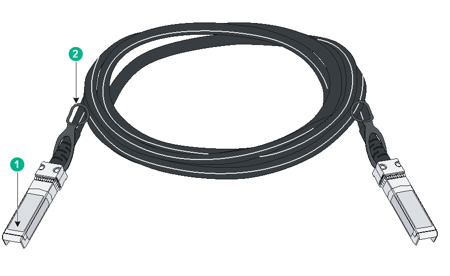
Figure3-1 SFP+ cable
|
(1) Connector |
(2) Pull latch |
LEDs
System status LED
The system status LED shows the operating status of the switch.
Table3-9 System status LED description
|
LED mark |
Status |
Description |
|
SYS |
Steady green |
The switch has started up correctly. |
|
Flashing green |
POST in progress. |
|
|
Steady red |
The switch has failed POST or the switch is faulty. |
|
|
Off |
The switch is powered off or has not started up correctly. |
RPS power supply status LED
The S1850-52X-PWR switch supports power input from an RPS power supply. You can determine the RPS power supply operating status by observing the RPS power supply status LED.
Table3-10 RPS power supply status LED description
|
LED mark |
Status |
Description |
|
RPS |
Steady green |
Normal AC power input and normal DC power input |
|
Steady yellow |
Normal DC power input, abnormal or no AC power input. |
|
|
Off |
Abnormal or no DC power input. |
Mode LED (MODE)
Each PoE switch provides a mode LED (MODE). The mode LED works in conjunction with the Ethernet port LEDs to indicate the operating state of the Ethernet ports and the switch.
You can use the LED mode switching button to change the indication of the mode LED.
Table3-11 Description for the mode LED
|
LED mark |
Status |
Description |
|
Mode LED (MODE) |
Steady green |
The Ethernet port LEDs are showing link state of the ports. |
|
Flashing green |
The Ethernet port LEDs are showing the PoE status of the ports. |
SFP/SFP+ port LED
Table3-12 SFP/SFP+ port LED description
|
Status |
Description |
|
Steady green |
A link is present on the port. |
|
Flashing green |
The port is sending or receiving data. |
|
Off |
· No link is present on the port. · The mode LED is operating in PoE mode (available only for PoE switch models) |
10/100/1000BASE-T autosensing Ethernet port LEDs
On a PoE switch, 10/100/1000BASE-T autosensing Ethernet port LEDs work in conjunction with the mode LED to indicate the operating state of the Ethernet ports and the switch from different aspects. Table3-13 describes the Ethernet port LEDs on a PoE switch.
Table3-14 describes the Ethernet port LEDs on a non-PoE switch.
Table3-13 Ethernet port LED description for PoE switch models
|
Mode LED status |
Ethernet port LED status |
Description |
|
Steady green (Link/Active mode) |
Steady green |
A link is present on the port. |
|
Flashing green |
The port is sending or receiving data. |
|
|
Off |
No link is present on the port. |
|
|
Flashing green (PoE mode) |
Steady green |
PoE power supply is normal. |
|
Flashing green (1 Hz) |
· The maximum PoE power provided by the port fails to meet the power requirement of the PD. · PoE power supply overcurrent, overvoltage, or short-circuit occurs. · The remaining power of the switch fails to meet the power supply requirement of the port. |
|
|
Off |
The port is not connected to a PD or PoE is not enabled on the port. |
Table3-14 Ethernet port LED description for non-PoE switch models
|
LED status |
Description |
|
Steady green |
A link is present on the port. |
|
Flashing green |
The port is sending or receiving data. |
|
Off |
No link is present on the port. |
