- Table of Contents
- Related Documents
-
| Title | Size | Download |
|---|---|---|
| 02-VXLAN IP gateway configuration | 544.13 KB |
VXLAN IP gateways separated from VTEPs
Centralized VXLAN IP gateway deployment
Centralized VXLAN gateway group deployment
Distributed VXLAN IP gateway deployment
Restrictions and guidelines: VXLAN IP gateway configuration
VXLAN IP gateway tasks at a glance
Prerequisites for VXLAN IP gateway configuration
Configuring a centralized VXLAN IP gateway
Configuring a gateway interface on a centralized VXLAN IP gateway
Configuring a centralized VXLAN IP gateway group
Specifying a VTEP group as the gateway for an access layer VTEP
Configuring a distributed VXLAN IP gateway
Restrictions and guidelines for distributed VXLAN IP gateway configuration
Configuring a gateway interface on a distributed VXLAN IP gateway
Enabling dynamic ARP or ND entry synchronization for distributed VXLAN IP gateways
Managing ARP entries and ND entries
Disabling remote ARP or ND learning for VXLANs
Configuring optional parameters for a VSI interface
Restoring the default settings of the VSI interface
Verifying and maintaining VXLAN IP gateways
Displaying information about VSI interfaces
Clearing statistics on VSI interfaces
VXLAN IP gateway configuration examples
Example: Configuring a centralized VXLAN IP gateway
Example: Configuring a centralized VXLAN IP gateway group
Example: Configuring distributed VXLAN IPv4 gateways
Example: Configuring distributed VXLAN IPv6 gateways
Configuring VXLAN IP gateways
About VXLAN IP gateways
The following are available IP gateway placement designs for VXLANs:
· VXLAN IP gateways separated from VTEPs—Use a VXLAN-unaware device as a gateway to the external network for VXLANs. On the gateway, you do not need to configure VXLAN settings.
· VXLAN IP gateways collocated with VTEPs—Include the following placement designs:
¡ Centralized VXLAN IP gateway deployment—Use one VTEP to provide Layer 3 forwarding for VXLANs. Typically, the gateway-collocated VTEP connects to other VTEPs and the external network. To use this design, make sure the IP gateway has sufficient bandwidth and processing capability. Centralized VXLAN IP gateways provide services only for IPv4 networks.
¡ Centralized VXLAN gateway group deployment—Use one VTEP group that contains redundant centralized VXLAN IP gateways to provide reliable gateway services for VXLANs.
¡ Distributed VXLAN IP gateway deployment—Deploy one VXLAN IP gateway on each VTEP to provide Layer 3 forwarding for VXLANs at their respective sites. This design distributes the Layer 3 traffic load across VTEPs. However, its configuration is more complex than the centralized VXLAN IP gateway design. Distributed gateways can provide services for both IPv4 and IPv6 networks.
In a collocation design, the VTEPs use virtual Layer 3 VSI interfaces as gateway interfaces to provide services for VXLANs.
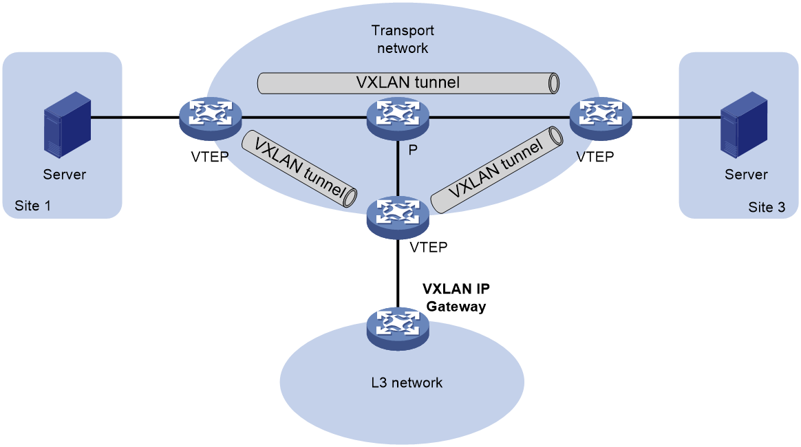
VXLAN IP gateways separated from VTEPs
As shown in Figure 1, an independent VXLAN IP gateway connects a Layer 3 network to a VTEP. VMs send Layer 3 traffic in Layer 2 frames to the gateway through VXLAN tunnels. When the tunneled VXLAN packets arrive, the VTEP terminates the VXLANs and forwards the inner frames to the gateway. In this gateway placement design, the VTEP does not perform Layer 3 forwarding for VXLANs.
Figure 1 VXLAN IP gateway separated from VTEPs
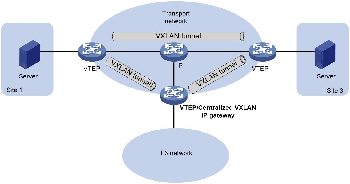
Centralized VXLAN IP gateway deployment
As shown in Figure 2, a VTEP acts as a gateway for VMs in the VXLANs. The VTEP both terminates the VXLANs and performs Layer 3 forwarding for the VMs.
Figure 2 Centralized VXLAN IP gateway placement design
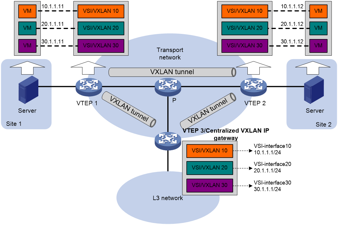
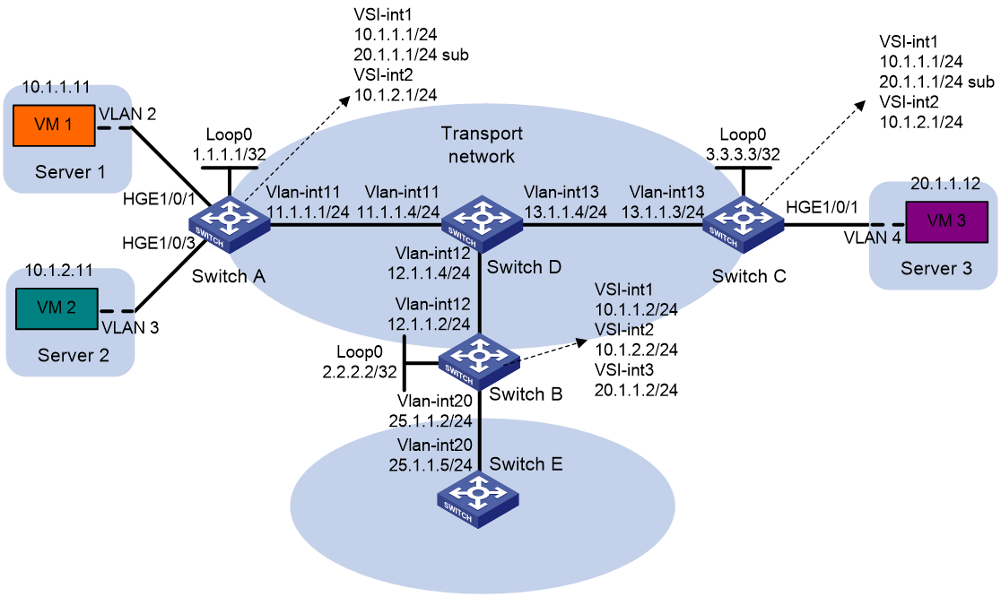
As shown in Figure 3, the network uses the following process to forward Layer 3 traffic from VM 10.1.1.11 to the Layer 3 network:
1. The VM sends an ARP request to obtain the MAC address of the gateway (VTEP 3) at 10.1.1.1.
2. VTEP 1 floods the ARP request to all remote VTEPs.
3. VTEP 3 de-encapsulates the ARP request, creates an ARP entry for the VM, and sends an ARP reply to the VM.
4. VTEP 1 forwards the ARP reply to the VM.
5. The VM learns the MAC address of the gateway, and sends the Layer 3 traffic to the gateway.
6. VTEP 3 removes the VXLAN encapsulation and inner Ethernet header for the traffic, and forwards the traffic to the destination node.
Inter-VXLAN forwarding is the same as this process except for the last step. At the last step of inter-VLAN forwarding, the gateway replaces the source-VXLAN encapsulation with the destination-VXLAN encapsulation, and then forwards the traffic.
Figure 3 Example of centralized VXLAN IP gateway deployment
Centralized VXLAN gateway group deployment
As shown in Figure 4, a VTEP group uses redundant centralized VXLAN IP gateways to provide reliable gateway services for VMs in the VXLANs. All member VTEPs in the group participate in Layer 3 forwarding and load share traffic between the Layer 3 network and the VXLANs. This design distributes processing among multiple VTEPs and prevents single points of failure.
Figure 4 Example of centralized VXLAN IP gateway group deployment
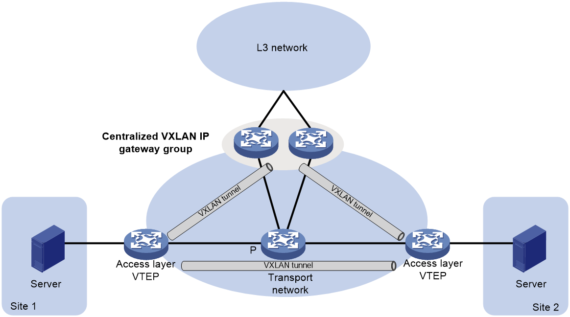
The VTEP group is a virtual gateway that provides services at a group IP address. Access layer VTEPs set up VXLAN tunnels to the group IP address for data traffic forwarding. Each access layer VTEP also automatically sets up tunnels to the member IP addresses of VTEPs in the VTEP group. These tunnels are used for transmitting broadcast, multicast, and unknown unicast floods, so that all VTEPs in the VTEP group have consistent forwarding entries.
Distributed VXLAN IP gateway deployment
About distributed VXLAN IP gateway deployment
As shown in Figure 5, each site's VTEP acts as a gateway to perform Layer 3 forwarding for the VXLANs of the local site. A VTEP acts as a border gateway to the Layer 3 network for the VXLANs.
Figure 5 Distributed VXLAN IP gateway placement design
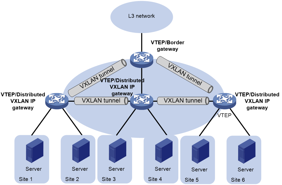
Figure 6 shows an example of distributed VXLAN IP gateway deployment. Create VSI interfaces on each distributed VXLAN IP gateway and the border gateway as gateway interfaces. Assign the same IP address to the same VSI interface on the distributed VXLAN IP gateways. Enable one of the following features on a distributed VXLAN IP gateway:
· ARP or ND flood suppression. The gateway performs Layer 2 forwarding based on MAC address entries and performs Layer 3 forwarding based on ARP or ND entries.
· Local proxy ARP or local ND proxy. The gateway performs Layer 3 forwarding based on ARP or ND entries. The following sections use distributed VXLAN IP gateways enabled with the local proxy ARP or local ND proxy feature to describe the forwarding processes for intra-VXLAN traffic, inter-VXLAN traffic, and traffic from a VXLAN to an external network.
A distributed VXLAN IP gateway can generate ARP or ND entries by a variety of methods. The following sections use dynamically learned ARP or ND entries to describe the forwarding processes.
Figure 6 Example of distributed VXLAN IP gateway deployment
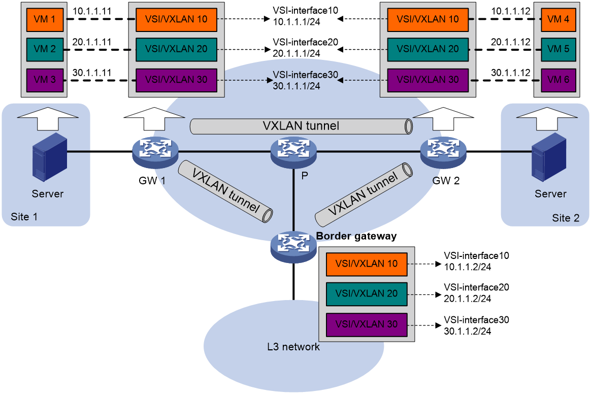
Intra-VXLAN traffic forwarding between sites
As shown in Figure 6, the network uses the following process to forward traffic in a VXLAN between sites (for example, from VM 1 to VM 4 in VXLAN 10):
1. VM 1 sends an ARP request to obtain the MAC address of VM 4.
2. GW 1 performs the following operations:
a. Creates an ARP entry for VM 1 and replies with the MAC address of VSI-interface 10 (the gateway interface for VXLAN 10).
b. Replaces the sender MAC address of the ARP request with the MAC address of VSI-interface 10, and then floods the request to all remote VTEPs.
3. VM 1 creates an ARP entry for VM 4. The MAC address in the entry is the MAC address of VSI-interface 10 on GW 1.
4. GW 2 (the VTEP for VM 4) performs the following operations:
a. De-encapsulates the ARP request and creates an ARP entry for VM 1. The entry contains VM 1's IP address (10.1.1.11), the MAC address of VSI-interface 10 on GW 1, and the incoming tunnel interface.
b. Replaces the sender MAC address of the request with the MAC address of VSI-interface 10 on GW 2, and then floods the request to the local site in VXLAN 10.
5. VM 4 creates an ARP entry for VM 1, and then sends a reply to GW 2. The MAC address in the ARP entry is the MAC address of VSI-interface 10 on GW 2.
6. GW 2 performs the following operations:
a. Creates an ARP entry for VM 4.
b. Replaces the sender MAC address of the request with the MAC address of VSI-interface 10 on GW 2, and sends the reply to GW 1.
7. GW 1 de-encapsulates the ARP request and creates an ARP entry for VM 4. The entry contains VM 4's IP address (10.1.1.12), the MAC address of VSI-interface 10 on GW 2, and the incoming tunnel interface.
8. For subsequent traffic between VM 1 and VM 4, GW 1 and GW 2 use their respective ARP tables to make the forwarding decision.
Inter-VXLAN traffic forwarding between sites
As shown in Figure 6, the network uses the following process to forward traffic between VXLANs (for example, from VM 1 in VXLAN 10 to VM 5 in VXLAN 20):
1. VM 1 sends an ARP request to obtain the MAC address of the gateway at 10.1.1.1.
2. GW 1 creates an ARP entry for VM 1 and replies with the MAC address of VSI-interface 10 (the gateway interface for VXLAN 10).
3. VM 1 sends the packet destined for VM 5 to GW 1.
4. GW 1 sends an ARP request to the local site and remote sites to obtain the MAC address of VM 5. In the ARP request, the sender IP address is 20.1.1.1, and the sender MAC address is the MAC address of VSI-interface 20 on GW 1.
5. GW 2 performs the following operations:
a. De-encapsulates the ARP request and creates an ARP entry for GW 1. The entry contains IP address 20.1.1.1 and MAC address of VSI-interface 20 on GW 1, and the incoming tunnel interface.
b. Replaces the sender MAC address of the request with the MAC address of VSI-interface 20 on GW 2, and then floods the request to the local site in VXLAN 20.
6. VM 5 creates an ARP entry for GW 2, and then sends a reply to GW 2. The entry contains the IP address (20.1.1.1) and MAC address of VSI-interface 20 on GW 2).
7. GW 2 performs the following operations:
a. Creates an ARP entry for VM 5.
b. Replaces the sender MAC address in the request with the MAC address of VSI-interface 20 on GW 2, and then sends the reply to GW 1.
8. GW 1 de-encapsulates the ARP request and creates an ARP entry for VM 5. The entry contains VM 5's IP address 20.1.1.12, the MAC address of VSI-interface 20 on GW 2, and the incoming tunnel interface.
9. For subsequent traffic between VM 1 and VM 5, GW 1 and GW 2 use their respective ARP tables to make the forwarding decision.
VXLAN-to-external network traffic forwarding
As shown in Figure 6, the network uses the following process to forward traffic from a VXLAN to the Layer 3 network (for example, from VM 1 to the host at 50.1.1.1):
1. VM 1 sends an ARP request to obtain the MAC address of the gateway at 10.1.1.1.
2. GW 1 creates an ARP entry for VM 1 and replies with the MAC address of VSI-interface 10 (the gateway interface for VXLAN 10).
3. VM 1 sends a packet destined for the host to GW 1.
4. GW 1 performs the following operations:
a. Searches the IP routing policies or routing table for the next hop. In this example, the next hop for the packet is 10.1.1.2 (the border gateway).
b. Floods an ARP request to the local and remote sites in VXLAN 10 to obtain the MAC address of 10.1.1.2.
5. The border gateway de-encapsulates the ARP request, creates an ARP entry for GW 1, and tunnels a reply to GW 1.
6. GW 1 de-encapsulates the ARP reply and creates an ARP entry for 10.1.1.2.
7. GW 1 sends the packet destined for the host to the border gateway.
8. The border gateway de-encapsulates the packet and forwards it to the host.
Restrictions and guidelines: VXLAN IP gateway configuration
Do not configure both centralized VXLAN IP gateway settings and centralized VXLAN IP gateway group settings on a device.
When you apply PBR policies to a VSI interface, make sure the VSI interface is associated with only one VSI.
VXLAN IP gateway tasks at a glance
To configure a VXLAN IP gateway, perform the following tasks:
1. Configure a VXLAN IP gateway
Choose one of the following tasks:
¡ Configuring a centralized VXLAN IP gateway
¡
¡ Configuring a distributed VXLAN IP gateway
2. (Optional.) Managing ARP entries and ND entries
3. (Optional.) Configuring a VSI interface
4. (Optional.)
Prerequisites for VXLAN IP gateway configuration
Before you configure a centralized or distributed VXLAN IP gateway, you must perform the following tasks on VTEPs:
· Create VSIs and VXLANs.
· Configure VXLAN tunnels and assign them to VXLANs.
For more information about the VXLAN configuration, see "Configuring basic VXLAN features."
Configuring a centralized VXLAN IP gateway
Restrictions and guidelines
Do not execute the local-proxy-arp enable command on a centralized VXLAN IP gateway.
Configuring a gateway interface on a centralized VXLAN IP gateway
1. Enter system view.
system-view
2. Create a VSI interface and enter VSI interface view.
interface vsi-interface vsi-interface-id
3. Assign an IPv4 address to the VSI interface.
ip address ip-address { mask | mask-length }
By default, no IPv4 address is assigned to a VSI interface.
4. Return to system view.
quit
5. Enter VSI view.
vsi vsi-name
6. Specify a gateway interface for the VSI.
gateway vsi-interface vsi-interface-id
By default, no gateway interface is specified for a VSI.
Assigning a subnet to a VSI
About this task
Perform this task on VSIs that share a gateway interface. This task enables the VSI interface to identify the VSI of a packet.
You can assign a maximum of eight IPv4 and IPv6 subnets to a VSI. Make sure these subnets are on the same network as one of the IP addresses on the gateway interface.
For VSIs that share a gateway interface, the subnets must be unique.
If you remove the gateway interface from the VSI, the VSI's subnet settings are automatically deleted.
Procedure
1. Enter system view.
system-view
2. Enter VSI view.
vsi vsi-name
3. Assign a subnet to the VSI.
gateway subnet ipv4-address wildcard-mask
By default, no subnet exists on a VSI.
Configuring a centralized VXLAN IP gateway group
Configuring a VTEP group
Restrictions and guidelines
Make sure the member VTEPs use the same VXLAN settings.
Procedure
1. Enter system view.
system-view
2. Create a VSI interface and enter VSI interface view.
interface vsi-interface vsi-interface-id
This interface will be used as the gateway interface for the VSI.
3. Assign an IP address to the VSI interface.
ip address ipv4-address { mask | mask-length }
By default, no IP address is assigned to a VSI interface.
You must assign the same IP address to the VSI interface on each VTEP in the VTEP group.
4. Assign a MAC address to the VSI interface.
mac-address mac-address
By default, VSI interfaces use the default MAC address of Layer 3 Ethernet interfaces.
You must assign the same MAC address to the VSI interface on each VTEP in the VTEP group.
5. Return to system view.
quit
6. Enter VSI view.
vsi vsi-name
7. Specify the VSI interface as the gateway interface for the VSI.
gateway vsi-interface vsi-interface-id
By default, no gateway interface is specified for a VSI.
8. Return to system view.
quit
9. Assign the local VTEP to a VTEP group and specify a member IP address for the VTEP.
vtep group group-ip member local member-ip
By default, a VTEP is not assigned to any VTEP group.
The specified member IP address must already exist on the local VTEP and be unique in the VTEP group. You must configure a routing protocol to advertise the IP address to the transport network.
10. Specify the member IP address of all the other VTEPs in the VTEP group.
vtep group group-ip member remote member-ip&<1-8>
By default, the list of remote VTEPs is not configured.
Specifying a VTEP group as the gateway for an access layer VTEP
Prerequisites
Before you specify a VTEP group on an access layer VTEP, perform the following tasks on the VTEP:
· Enable Layer 2 forwarding for VXLANs.
· Configure VSIs and VXLANs.
· Set up VXLAN tunnels to remote sites and the VTEP group, and assign the tunnels to VXLANs.
Procedure
1. Enter system view.
system-view
2. Specify a VTEP group and all its member VTEPs.
vtep group group-ip member remote member-ip&<1-8>
By default, no VTEP group is specified.
Perform this task to specify all member VTEPs in the VTEP group.
Configuring a distributed VXLAN IP gateway
Restrictions and guidelines for distributed VXLAN IP gateway configuration
For a VXLAN that requires access to the external network, specify the VXLAN's VSI interface on the border gateway as the next hop by using one of the following methods:
· Configure a static route.
· Configure a routing policy, and apply the policy by using the apply default-next-hop command. For more information about configuring routing policies, see routing policy configuration in Layer 3—IP Routing Configuration Guide.
If both ARP flood suppression and local proxy ARP are enabled on a distributed VXLAN IP gateway, only local proxy ARP takes effect. As a best practice, do not use these features together on distributed VXLAN IP gateways. For more information about ARP flood suppression, see "VXLAN overview."
Make sure a VSI interface uses the same MAC address to provide service on distributed VXLAN IP gateways connected to IPv4 sites. Make sure a VSI interface uses different link-local addresses to provide service on distributed VXLAN IP gateways connected to both IPv4 and IPv6 sites.
Configuring a gateway interface on a distributed VXLAN IP gateway
1. Enter system view.
system-view
2. Create a VSI interface and enter VSI interface view.
interface vsi-interface vsi-interface-id
3. Assign an IP address to the VSI interface.
IPv4:
ip address ip-address { mask | mask-length } [ sub ]
IPv6:
See IPv6 basics in Layer 3—IP Services Configuration Guide.
By default, no IP address is assigned to a VSI interface.
4. Specify the VSI interface as a distributed gateway.
distributed-gateway local
By default, a VSI interface is not a distributed gateway.
5. Enable local proxy ARP or local ND proxy.
IPv4:
local-proxy-arp enable [ ip-range startIP to endIP ]
By default, local proxy ARP is disabled.
For more information about this command, see proxy ARP commands in Layer 3—IP Services Command Reference.
IPv6:
local-proxy-nd enable
By default, local ND proxy is disabled.
For more information about this command, see IPv6 neighbor discovery commands in Layer 3—IP Services Command Reference.
6. Bring up the VSI interface.
undo shutdown
By default, a VSI interface is up.
7. Return to system view.
quit
8. Enter VSI view.
vsi vsi-name
9. Specify the VSI interface as the gateway interface for the VSI.
gateway vsi-interface vsi-interface-id
By default, no gateway interface is specified for a VSI.
Enabling dynamic ARP or ND entry synchronization for distributed VXLAN IP gateways
About this task
When local proxy ARP or local ND proxy is enabled on distributed VXLAN IP gateways, enable this feature for all gateways to have the same ARP or ND entries.
A controller or the EVPN feature can also synchronize ARP or ND entries among distributed VXLAN IP gateways. When you use a controller or the EVPN feature, do not enable dynamic ARP or ND entry synchronization.
Enabling dynamic ARP entry synchronization
1. Enter system view.
system-view
2. Enable dynamic ARP entry synchronization for distributed VXLAN IP gateways.
arp distributed-gateway dynamic-entry synchronize
By default, dynamic ARP entry synchronization is disabled for distributed VXLAN IP gateways.
Enabling dynamic ND entry synchronization
1. Enter system view.
system-view
2. Enable dynamic ND entry synchronization for distributed VXLAN IP gateways.
ipv6 nd distributed-gateway dynamic-entry synchronize
By default, dynamic ND entry synchronization is disabled for distributed VXLAN IP gateways.
Assigning a subnet to a VSI
About this task
Perform this task on VSIs that share a gateway interface. This task enables the VSI interface to identify the VSI of a packet.
You can assign a maximum of eight IPv4 and IPv6 subnets to a VSI. Make sure these subnets are on the same network as one of the IP addresses on the gateway interface.
For VSIs that share a gateway interface, the subnets must be unique.
If you remove the gateway interface from the VSI, the VSI's subnet settings are automatically deleted.
Procedure
1. Enter system view.
system-view
2. Enter VSI view.
vsi vsi-name
3. Assign a subnet to the VSI.
gateway subnet { ipv4-address wildcard-mask | ipv6-address prefix-length }
By default, no subnet exists on a VSI.
Managing ARP entries and ND entries
Adding a static ARP entry
About this task
A VXLAN IP gateway can dynamically learn ARP entries and use manually configured static ARP entries.
Procedure
1. Enter system view.
system-view
2. Add a static local-ARP entry.
arp static ip-address mac-address vsi-interface vsi-interface-id interface-type interface-number service-instance instance-id vsi vsi-name [ vpn-instance vpn-instance-name ]
For more information about this command, see ARP commands in Layer 3—IP Services Command Reference.
3. Add a static remote-ARP entry.
arp static ip-address mac-address vsi-interface vsi-interface-id tunnel number vsi vsi-name [ vpn-instance vpn-instance-name ]
For more information about this command, see ARP commands in Layer 3—IP Services Command Reference.
Disabling remote ARP or ND learning for VXLANs
About this task
By default, the device learns ARP or ND information of remote user terminals from packets received on VXLAN tunnel interfaces. To save resources on VTEPs in an SDN transport network, you can temporarily disable remote ARP or ND learning when the controller and VTEPs are synchronizing entries. After the entry synchronization is completed, enable remote ARP or ND learning.
Restrictions and guidelines
As a best practice, disable remote ARP or ND learning for VXLANs only when the controller and VTEPs are synchronizing entries.
Procedure
1. Enter system view.
system-view
2. Disable remote ARP learning.
vxlan tunnel arp-learning disable
By default, remote ARP learning is enabled for VXLANs.
3. Disable remote ND learning.
vxlan tunnel nd-learning disable
By default, remote ND learning is enabled for VXLANs.
Configuring a VSI interface
Configuring optional parameters for a VSI interface
Restrictions and guidelines
For more information about the bandwidth and description commands, see common interface commands in Interface Command Reference.
Procedure
1. Enter system view.
system-view
2. Enter VSI interface view.
interface vsi-interface vsi-interface-id
3. Assign a MAC address to the VSI interface.
mac-address mac-address
By default, VSI interfaces use the default MAC address of Layer 3 Ethernet interfaces.
4. Configure the description of the VSI interface.
description text
The default description of a VSI interface is interface-name plus Interface (for example, Vsi-interface100 Interface).
5. Set the expected bandwidth for the VSI interface.
bandwidth bandwidth-value
The default expected bandwidth (in kbps) equals the interface baudrate divided by 1000.
The expected bandwidth is an informational parameter used only by higher-layer protocols for calculation. You cannot adjust the actual bandwidth of an interface by using this command.
6. Set an ARP packet sending rate limit for the VSI interface.
arp send-rate pps
By default, the ARP packet sending rate is not limited for a VSI interface.
This limit applies only to the ARP request packets sourced from the VSI interface.
Restoring the default settings of the VSI interface
Restrictions and guidelines
|
|
CAUTION: This operation might interrupt ongoing network services. Make sure you are fully aware of the impact of this operation when you perform it on a live network. |
This operation might fail to restore the default settings for some commands for reasons such as command dependencies or system restrictions. Use the display this command in interface view to identify these commands. Use their undo forms or follow the command reference to restore their default settings. If your restoration attempt still fails, follow the error message instructions to resolve the problem. For more information about the default command, see common interface commands in Interface Command Reference.
Procedure
1. Enter system view.
system-view
2. Enter VSI interface view.
interface vsi-interface vsi-interface-id
3. Restore the default settings of the VSI interface.
default
Configuring VXLAN M-LAG
About this task
VXLAN M-LAG virtualizes two VTEPs or VXLAN IP gateways into one M-LAG system to avoid single points of failure.
Restrictions and guidelines
When you configure VXLAN M-LAG, follow these restrictions and guidelines:
· An M-LAG system does not support Layer 2 multicast.
· M-LAG member devices must use the same tunnel source address to establish VXLAN tunnels to remote devices.
If a direct peer link is used, follow these restrictions:
· If the frame match criteria of dynamic ACs on the peer link are created based on site-facing Ethernet service instances, you can configure only the following criteria for site-facing Ethernet service instances:
¡ encapsulation s-vid { vlan-id | vlan-id-list }
¡ encapsulation untagged
In addition, you must set the access mode to VLAN for site-facing Ethernet service instances.
· Make sure the Ethernet service instances that use the same match criterion are mapped to the same VSI.
· Make sure the following settings are consistent on the M-LAG member devices:
¡ Ethernet service instances and their match criterion on the M-LAG interfaces in the same M-LAG group or single-homed site-facing interfaces.
¡ VXLAN IDs of VSIs.
In addition, the Ethernet service instances must be created manually.
If a tunnel peer link is used, follow these restrictions:
· As a best practice, use different physical interfaces as the traffic outgoing interfaces of the tunnel peer link and non-peer link VXLAN tunnels.
· To prioritize transmission of M-LAG protocol packets on the peer link, use the tunnel tos command on the VXLAN tunnel interface to set a high ToS value for tunneled packets.
· You must disable spanning tree on the Layer 2 Ethernet interface that acts as the physical traffic outgoing interface of the tunnel peer link. If you enable spanning tree on that interface, the upstream device will block the interfaces connected to the M-LAG member devices.
· Use the reserved vxlan command to specify a reserved VXLAN to forward M-LAG protocol packets. The M-LAG member devices in an M-LAG system must have the same reserved VXLAN.
· Make sure the following settings are consistent on the M-LAG member devices:
¡ Ethernet service instances and their match criterion on the M-LAG interfaces in the same M-LAG group.
¡ VXLAN IDs of VSIs.
In addition, the Ethernet service instances must be created manually.
The VTEPs in an M-LAG system synchronize local MAC address entries with each other over the peer link. However, they do not synchronize MAC address entry deletions. When you delete a MAC address entry from one VTEP, the other VTEP retains the entry that contains the same MAC address until the entry ages out.
Procedure
1. Configure M-LAG as described in Layer 2—LAN Switching Configuration Guide.
2. Exclude interfaces from the shutdown action by M-LAG MAD.
m-lag mad exclude interface interface-type interface-number
By default, M-LAG MAD shuts down all network interfaces when detecting a multi-active collision, except for the network interfaces set by the system to not shut down.
Exclude all interfaces used by VXLAN from the MAD shutdown action by M-LAG. The interfaces include VSI interfaces, interfaces used for setting up the keepalive link, and transport-facing outgoing interfaces of VXLAN tunnels. Also exclude peer-link interfaces from the shutdown action by M-LAG MAD if the peer link is a VXLAN tunnel.
For more information about this command, see M-LAG commands in Layer 2—LAN Switching Command Reference.
3. Set the data restoration interval.
m-lag restore-delay value
By default, the data restoration interval is 30 seconds.
Set the data restoration interval to a value equal to or larger than 180 seconds on a VXLAN M-LAG system.
For more information about this command, see M-LAG commands in Layer 2—LAN Switching Command Reference.
4. (Optional.) Enable the device to create frame match criteria based on VXLAN IDs for the dynamic ACs on the direct peer link.
l2vpn m-lag peer-link ac-match-rule vxlan-mapping
By default, on an M-LAG system with a direct peer link, dynamic ACs on the peer link use frame match criteria that are identical to those of site-facing ACs.
If you do not execute this command, do not configure overlapping outer VLAN IDs for Ethernet service instances of different VSIs.
If you execute this command, do not create VXLANs with IDs larger than 16000000.
For more information about this command, see EVPN Command Reference.
Verifying and maintaining VXLAN IP gateways
Displaying information about VSI interfaces
To display information about VSI interfaces, execute the following command in any view:
display interface [ vsi-interface [ vsi-interface-id ] ] [ brief [ description | down ] ]
Clearing statistics on VSI interfaces
To clear statistics on VSI interfaces, execute the following command in user view:
reset counters interface [ vsi-interface [ vsi-interface-id ] ]
For more information about this command, see common interface commands in Interface Command Reference.
VXLAN IP gateway configuration examples
Example: Configuring a centralized VXLAN IP gateway
Network configuration
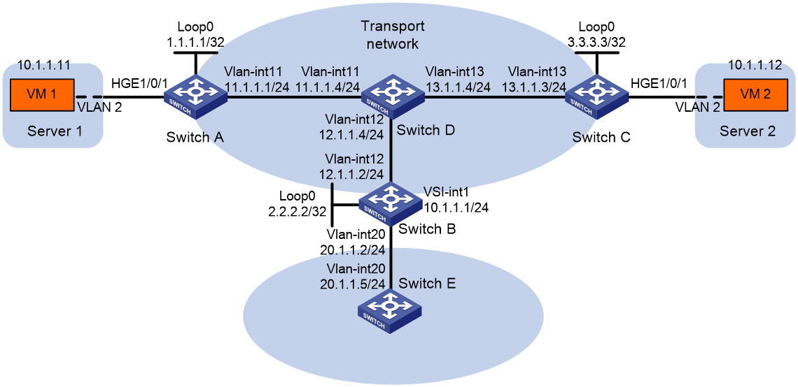
As shown in Figure 7:
· Configure VXLAN 10 as a unicast-mode VXLAN on Switch A, Switch B, and Switch C to provide connectivity for the VMs across the network sites.
· Configure a centralized VXLAN IP gateway on Switch B to provide gateway services for VXLAN 10.
· Manually establish VXLAN tunnels and assign the tunnels to VXLAN 10.
· Enable remote-MAC address learning.
Procedure
|
|
IMPORTANT: By default, interfaces on the device are disabled (in ADM or Administratively Down state). To have an interface operate, you must use the undo shutdown command to enable that interface. By default, interfaces on the device operate in Layer 3 mode. In this example, you must use the port link-mode command to configure the interfaces that host Ethernet service instances to operate in Layer 2 mode. |
1. On VM 1 and VM 2, specify 10.1.1.1 as the gateway address. (Details not shown.)
2. Configure IP addresses and unicast routing settings:
# Assign IP addresses to interfaces, as shown in Figure 7. (Details not shown.)
# Configure OSPF on all transport network switches (Switches A through D). (Details not shown.)
# Configure OSPF to advertise routes to networks 10.1.1.0/24 and 20.1.1.0/24 on Switch B and Switch E. (Details not shown.)
3. Configure Switch A:
# Enable L2VPN.
<SwitchA> system-view
[SwitchA] l2vpn enable
# Create VSI vpna and VXLAN 10.
[SwitchA] vsi vpna
[SwitchA-vsi-vpna] vxlan 10
[SwitchA-vsi-vpna-vxlan-10] quit
[SwitchA-vsi-vpna] quit
# Assign an IP address to Loopback 0. The IP address will be used as the source IP address of the VXLAN tunnels to Switch B and Switch C.
[SwitchA] interface loopback 0
[SwitchA-Loopback0] ip address 1.1.1.1 255.255.255.255
[SwitchA-Loopback0] quit
# Create a VXLAN tunnel to Switch B. The tunnel interface name is Tunnel 1.
[SwitchA] interface tunnel 1 mode vxlan
[SwitchA-Tunnel1] source 1.1.1.1
[SwitchA-Tunnel1] destination 2.2.2.2
[SwitchA-Tunnel1] quit
# Create a VXLAN tunnel to Switch C. The tunnel interface name is Tunnel 2.
[SwitchA] interface tunnel 2 mode vxlan
[SwitchA-Tunnel2] source 1.1.1.1
[SwitchA-Tunnel2] destination 3.3.3.3
[SwitchA-Tunnel2] quit
# Assign Tunnel 1 and Tunnel 2 to VXLAN 10.
[SwitchA] vsi vpna
[SwitchA-vsi-vpna] vxlan 10
[SwitchA-vsi-vpna-vxlan-10] tunnel 1
[SwitchA-vsi-vpna-vxlan-10] tunnel 2
[SwitchA-vsi-vpna-vxlan-10] quit
[SwitchA-vsi-vpna] quit
# On HundredGigE 1/0/1, create Ethernet service instance 1000 to match VLAN 2.
[SwitchA] interface hundredgige 1/0/1
[SwitchA-HundredGigE1/0/1] port link-type trunk
[SwitchA-HundredGigE1/0/1] port trunk permit vlan 2
[SwitchA-HundredGigE1/0/1] service-instance 1000
[SwitchA-HundredGigE1/0/1-srv1000] encapsulation s-vid 2
# Map Ethernet service instance 1000 to VSI vpna.
[SwitchA-HundredGigE1/0/1-srv1000] xconnect vsi vpna
[SwitchA-HundredGigE1/0/1-srv1000] quit
[SwitchA-HundredGigE1/0/1] quit
4. Configure Switch B:
# Enable L2VPN.
<SwitchB> system-view
[SwitchB] l2vpn enable
# Create VSI vpna and VXLAN 10.
[SwitchB] vsi vpna
[SwitchB-vsi-vpna] vxlan 10
[SwitchB-vsi-vpna-vxlan-10] quit
[SwitchB-vsi-vpna] quit
# Assign an IP address to Loopback 0. The IP address will be used as the source IP address of the VXLAN tunnels to Switch A and Switch C.
[SwitchB] interface loopback 0
[SwitchB-Loopback0] ip address 2.2.2.2 255.255.255.255
[SwitchB-Loopback0] quit
# Create a VXLAN tunnel to Switch A. The tunnel interface name is Tunnel 2.
[SwitchB] interface tunnel 2 mode vxlan
[SwitchB-Tunnel2] source 2.2.2.2
[SwitchB-Tunnel2] destination 1.1.1.1
[SwitchB-Tunnel2] quit
# Create a VXLAN tunnel to Switch C. The tunnel interface name is Tunnel 3.
[SwitchB] interface tunnel 3 mode vxlan
[SwitchB-Tunnel3] source 2.2.2.2
[SwitchB-Tunnel3] destination 3.3.3.3
[SwitchB-Tunnel3] quit
# Assign Tunnel 2 and Tunnel 3 to VXLAN 10.
[SwitchB] vsi vpna
[SwitchB-vsi-vpna] vxlan 10
[SwitchB-vsi-vpna-vxlan-10] tunnel 2
[SwitchB-vsi-vpna-vxlan-10] tunnel 3
[SwitchB-vsi-vpna-vxlan-10] quit
[SwitchB-vsi-vpna] quit
# Create VSI-interface 1 and assign the interface an IP address. The IP address will be used as the gateway address for VXLAN 10.
[SwitchB] interface vsi-interface 1
[SwitchB-Vsi-interface1] ip address 10.1.1.1 255.255.255.0
[SwitchB-Vsi-interface1] quit
# Specify VSI-interface 1 as the gateway interface for VSI vpna.
[SwitchB] vsi vpna
[SwitchB-vsi-vpna] gateway vsi-interface 1
[SwitchB-vsi-vpna] quit
5. Configure Switch C:
# Enable L2VPN.
<SwitchC> system-view
[SwitchC] l2vpn enable
# Create VSI vpna and VXLAN 10.
[SwitchC] vsi vpna
[SwitchC-vsi-vpna] vxlan 10
[SwitchC-vsi-vpna-vxlan-10] quit
[SwitchC-vsi-vpna] quit
# Assign an IP address to Loopback 0. The IP address will be used as the source IP address of the VXLAN tunnels to Switch A and Switch B.
[SwitchC] interface loopback 0
[SwitchC-Loopback0] ip address 3.3.3.3 255.255.255.255
[SwitchC-Loopback0] quit
# Create a VXLAN tunnel to Switch A. The tunnel interface name is Tunnel 1.
[SwitchC] interface tunnel 1 mode vxlan
[SwitchC-Tunnel1] source 3.3.3.3
[SwitchC-Tunnel1] destination 1.1.1.1
[SwitchC-Tunnel1] quit
# Create a VXLAN tunnel to Switch B. The tunnel interface name is Tunnel 3.
[SwitchC] interface tunnel 3 mode vxlan
[SwitchC-Tunnel3] source 3.3.3.3
[SwitchC-Tunnel3] destination 2.2.2.2
[SwitchC-Tunnel3] quit
# Assign Tunnel 1 and Tunnel 3 to VXLAN 10.
[SwitchC] vsi vpna
[SwitchC-vsi-vpna] vxlan 10
[SwitchC-vsi-vpna-vxlan-10] tunnel 1
[SwitchC-vsi-vpna-vxlan-10] tunnel 3
[SwitchC-vsi-vpna-vxlan-10] quit
[SwitchC-vsi-vpna] quit
# On HundredGigE 1/0/1, create Ethernet service instance 1000 to match VLAN 2.
[SwitchC] interface hundredgige 1/0/1
[SwitchC-HundredGigE1/0/1] port link-type trunk
[SwitchC-HundredGigE1/0/1] port trunk permit vlan 2
[SwitchC-HundredGigE1/0/1] service-instance 1000
[SwitchC-HundredGigE1/0/1-srv1000] encapsulation s-vid 2
# Map Ethernet service instance 1000 to VSI vpna.
[SwitchC-HundredGigE1/0/1-srv1000] xconnect vsi vpna
[SwitchC-HundredGigE1/0/1-srv1000] quit
[SwitchC-HundredGigE1/0/1] quit
Verifying the configuration
1. Verify the VXLAN IP gateway settings on Switch B:
# Verify that the VXLAN tunnel interfaces are up on Switch B.
[SwitchB] display interface tunnel 2
Tunnel2
Current state: UP
Line protocol state: UP
Description: Tunnel2 Interface
Bandwidth: 64 kbps
Maximum transmission unit: 64000
Internet protocol processing: Disabled
Last clearing of counters: Never
Tunnel source 2.2.2.2, destination 1.1.1.1
Tunnel protocol/transport UDP_VXLAN/IP
Last 300 seconds input rate: 0 bytes/sec, 0 bits/sec, 0 packets/sec
Last 300 seconds output rate: 0 bytes/sec, 0 bits/sec, 0 packets/sec
Input: 0 packets, 0 bytes, 0 drops
Output: 0 packets, 0 bytes, 0 drops
# Verify that VSI-interface 1 is up.
[SwitchB] display interface vsi-interface 1
Vsi-interface1
Current state: UP
Line protocol state: UP
Description: Vsi-interface1 Interface
Bandwidth: 1000000 kbps
Maximum transmission unit: 1444
Internet address: 10.1.1.1/24 (primary)
IP packet frame type: Ethernet II, hardware address: 0011-2200-0102
IPv6 packet frame type: Ethernet II, hardware address: 0011-2200-0102
Physical: Unknown, baudrate: 1000000 kbps
Last clearing of counters: Never
# Verify that the VXLAN tunnels have been assigned to the VXLAN, and VSI-interface 1 is the gateway interface of VSI vpna.
[SwitchB] display l2vpn vsi verbose
VSI Name: vpna
VSI Index : 0
VSI State : Up
MTU : -
Diffserv Mode : -
Bandwidth : Unlimited
Broadcast Restrain : Unlimited
Multicast Restrain : Unlimited
Unknown Unicast Restrain: Unlimited
MAC Learning : Enabled
MAC Table Limit : -
MAC Learning rate : -
Drop Unknown : -
PW Redundancy Mode : Slave
Flooding : Enabled
ESI : 0000.0000.0000.0000.0000
Redundancy Mode : All-active
Statistics : Disabled
Gateway interface : VSI-interface 1
VXLAN ID : 10
Tunnels:
Tunnel Name Link ID State Type Flood proxy
Tunnel2 0x5000002 Up Manual Disabled
Tunnel3 0x5000003 Up Manual Disabled
# Verify that Switch B has created ARP entries for the VMs.
[SwitchB] display arp
Type: S-Static D-Dynamic O-Openflow R-Rule I-Invalid
IP address MAC address VLAN/VSI name Interface Aging Type
20.1.1.5 000c-29c1-5e46 -- Vlan20 19 D
10.1.1.11 0000-1234-0001 vpna Tunnel2 20 D
10.1.1.12 0000-1234-0002 vpna Tunnel3 19 D
# Verify that Switch B has created FIB entries for the VMs.
[SwitchB] display fib 10.1.1.11
Destination count: 1 FIB entry count: 1
Flag:
U:Usable G:Gateway H:Host B:Blackhole D:Dynamic S:Static
R:Relay F:FRR
Destination/Mask Nexthop Flag OutInterface/Token Label
10.1.1.11/32 10.1.1.11 UH Vsi1 Null
2. Verify that the VMs can access the WAN:
# Verify that VM 1 and VM 2 can ping each other. (Details not shown.)
# Verify that VM 1, VM 2, and VLAN-interface 20 (20.1.1.5) on Switch E can ping each other. (Details not shown.)
Example: Configuring a centralized VXLAN IP gateway group
Network configuration
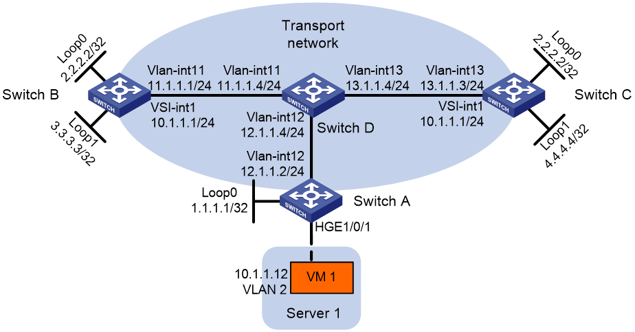
As shown in Figure 8:
· Configure VXLAN 10 as a unicast-mode VXLAN on Switch A, Switch B, and Switch C.
· Manually establish VXLAN tunnels and assign the tunnels to VXLAN 10.
· Assign Switch B and Switch C to a VTEP group to provide gateway services for VXLAN 10.
Procedure
|
|
IMPORTANT: By default, interfaces on the device are disabled (in ADM or Administratively Down state). To have an interface operate, you must use the undo shutdown command to enable that interface. By default, interfaces on the device operate in Layer 3 mode. In this example, you must use the port link-mode command to configure the interfaces that host Ethernet service instances to operate in Layer 2 mode. |
1. Create VLANs and VLAN interfaces on all devices. (Details not shown.)
2. On VM 1, specify 10.1.1.1 as the gateway address. (Details not shown.)
3. Configure IP addresses and unicast routing settings:
# Assign IP addresses to interfaces, as shown in Figure 8. (Details not shown.)
# Configure OSPF on all transport network switches (Switches A through D). (Details not shown.)
4. Configure Switch A:
# Enable L2VPN.
<SwitchA> system-view
[SwitchA] l2vpn enable
# Enable Layer 2 forwarding for VXLANs.
[SwitchA] undo vxlan ip-forwarding
# Create VSI vpna and VXLAN 10.
[SwitchA] vsi vpna
[SwitchA-vsi-vpna] vxlan 10
[SwitchA-vsi-vpna-vxlan-10] quit
[SwitchA-vsi-vpna] quit
# Assign an IP address to Loopback 0. The IP address will be used as the source IP address of the VXLAN tunnel to the VTEP group.
[SwitchA] interface loopback 0
[SwitchA-Loopback0] ip address 1.1.1.1 255.255.255.255
[SwitchA-Loopback0] quit
# Create a VXLAN tunnel to the VTEP group. The tunnel interface name is Tunnel 1.
[SwitchA] interface tunnel 1 mode vxlan
[SwitchA-Tunnel1] source 1.1.1.1
[SwitchA-Tunnel1] destination 2.2.2.2
[SwitchA-Tunnel1] quit
# Assign Tunnel 1 to VXLAN 10.
[SwitchA] vsi vpna
[SwitchA-vsi-vpna] vxlan 10
[SwitchA-vsi-vpna-vxlan-10] tunnel 1
[SwitchA-vsi-vpna-vxlan-10] quit
[SwitchA-vsi-vpna] quit
# On HundredGigE 1/0/1, create Ethernet service instance 1000 to match VLAN 2.
[SwitchA] interface hundredgige 1/0/1
[SwitchA-HundredGigE1/0/1] service-instance 1000
[SwitchA-HundredGigE1/0/1-srv1000] encapsulation s-vid 2
# Map Ethernet service instance 1000 to VSI vpna.
[SwitchA-HundredGigE1/0/1-srv1000] xconnect vsi vpna
[SwitchA-HundredGigE1/0/1-srv1000] quit
[SwitchA-HundredGigE1/0/1] quit
# Specify VTEP group 2.2.2.2 and its member VTEPs at 3.3.3.3 and 4.4.4.4.
[SwitchA] vtep group 2.2.2.2 member remote 3.3.3.3 4.4.4.4
5. Configure Switch B:
# Enable L2VPN.
<SwitchB> system-view
[SwitchB] l2vpn enable
# Create VSI vpna and VXLAN 10.
[SwitchB] vsi vpna
[SwitchB-vsi-vpna] vxlan 10
[SwitchB-vsi-vpna-vxlan-10] quit
[SwitchB-vsi-vpna] quit
# Assign IP address 2.2.2.2/32 to Loopback 0. The IP address will be used as the IP address of the VTEP group.
[SwitchB] interface loopback 0
[SwitchB-Loopback0] ip address 2.2.2.2 255.255.255.255
[SwitchB-Loopback0] quit
# Assign an IP address to Loopback 1. The IP address will be used as the member IP address of the VTEP.
[SwitchB] interface loopback 1
[SwitchB-Loopback1] ip address 3.3.3.3 255.255.255.255
[SwitchB-Loopback1] quit
# Create a VXLAN tunnel to Switch A. The tunnel source IP address is 2.2.2.2, and the tunnel interface name is Tunnel 2.
[SwitchB] interface tunnel 2 mode vxlan
[SwitchB-Tunnel2] source 2.2.2.2
[SwitchB-Tunnel2] destination 1.1.1.1
[SwitchB-Tunnel2] quit
# Assign Tunnel 2 to VXLAN 10.
[SwitchB] vsi vpna
[SwitchB-vsi-vpna] vxlan 10
[SwitchB-vsi-vpna-vxlan-10] tunnel 2
[SwitchB-vsi-vpna-vxlan-10] quit
[SwitchB-vsi-vpna] quit
# Create VSI-interface 1 and assign the interface an IP address and a MAC address. The IP address will be used as the gateway address for VXLAN 10.
[SwitchB] interface vsi-interface 1
[SwitchB-Vsi-interface1] ip address 10.1.1.1 255.255.255.0
[SwitchB-Vsi-interface1] mac-address 2-2-2
[SwitchB-Vsi-interface1] quit
# Specify VSI-interface 1 as the gateway interface for VSI vpna.
[SwitchB] vsi vpna
[SwitchB-vsi-vpna] gateway vsi-interface 1
[SwitchB-vsi-vpna] quit
# Assign the local VTEP to VTEP group 2.2.2.2, and specify the member IP address of the local VTEP.
[SwitchB] vtep group 2.2.2.2 member local 3.3.3.3
# Specify the other member VTEP Switch C.
[SwitchB] vtep group 2.2.2.2 member remote 4.4.4.4
6. Configure Switch C:
# Enable L2VPN.
<SwitchC> system-view
[SwitchC] l2vpn enable
# Create VSI vpna and VXLAN 10.
[SwitchC] vsi vpna
[SwitchC-vsi-vpna] vxlan 10
[SwitchC-vsi-vpna-vxlan-10] quit
[SwitchC-vsi-vpna] quit
# Assign IP address 2.2.2.2/32 to Loopback 0. The IP address will be used as the IP address of the VTEP group.
[SwitchC] interface loopback 0
[SwitchC-Loopback0] ip address 2.2.2.2 255.255.255.255
[SwitchC-Loopback0] quit
# Assign an IP address to Loopback 1. The IP address will be used as the member IP address of the VTEP.
[SwitchC] interface loopback 1
[SwitchC-Loopback1] ip address 4.4.4.4 255.255.255.255
[SwitchC-Loopback1] quit
# Create a VXLAN tunnel to Switch A. The tunnel source IP address is 2.2.2.2, and the tunnel interface name is Tunnel 2.
[SwitchC] interface tunnel 2 mode vxlan
[SwitchC-Tunnel2] source 2.2.2.2
[SwitchC-Tunnel2] destination 1.1.1.1
[SwitchC-Tunnel2] quit
# Assign Tunnel 2 to VXLAN 10.
[SwitchC] vsi vpna
[SwitchC-vsi-vpna] vxlan 10
[SwitchC-vsi-vpna-vxlan-10] tunnel 2
[SwitchC-vsi-vpna-vxlan-10] quit
[SwitchC-vsi-vpna] quit
# Create VSI-interface 1 and assign the interface an IP address and a MAC address. The IP address will be used as the gateway address for VXLAN 10.
[SwitchC] interface vsi-interface 1
[SwitchC-Vsi-interface1] ip address 10.1.1.1 255.255.255.0
[SwitchC-Vsi-interface1] mac-address 2-2-2
[SwitchC-Vsi-interface1] quit
# Specify VSI-interface 1 as the gateway interface for VSI vpna.
[SwitchC] vsi vpna
[SwitchC-vsi-vpna] gateway vsi-interface 1
[SwitchC-vsi-vpna] quit
# Assign the local VTEP to VTEP group 2.2.2.2, and specify the member IP address of the local VTEP.
[SwitchC] vtep group 2.2.2.2 member local 4.4.4.4
# Specify the other member VTEP Switch B.
[SwitchC] vtep group 2.2.2.2 member remote 3.3.3.3
Example: Configuring distributed VXLAN IPv4 gateways
Network configuration
As shown in Figure 9:
· Configure VXLAN 10, VXLAN 20, and VXLAN 30 as unicast-mode VXLANs on Switch A, Switch B, and Switch C to provide connectivity for the VMs across the network sites.
· Manually establish VXLAN tunnels and assign the tunnels to the VXLANs.
· Configure distributed VXLAN IP gateways on Switch A and Switch C to forward traffic between the VXLANs.
· Configure Switch B as a border gateway to forward traffic between the VXLANs and the WAN connected to Switch E.
Procedure
|
|
IMPORTANT: By default, interfaces on the device are disabled (in ADM or Administratively Down state). To have an interface operate, you must use the undo shutdown command to enable that interface. By default, interfaces on the device operate in Layer 3 mode. In this example, you must use the port link-mode command to configure the interfaces that host Ethernet service instances to operate in Layer 2 mode. |
1. On VM 1, VM 2, and VM 3, specify 10.1.1.1, 10.1.2.1, and 20.1.1.1 as the gateway address, respectively. (Details not shown.)
2. Configure IP addresses and unicast routing settings:
# Assign IP addresses to interfaces, as shown in Figure 9. (Details not shown.)
# Configure OSPF on all transport network switches (Switches A through D). (Details not shown.)
# Configure OSPF to advertise routes to networks 10.1.1.0/24, 10.1.2.0/24, 20.1.1.0/24, and 25.1.1.0/24 on Switch B and Switch E. (Details not shown.)
3. Configure Switch A:
# Enable L2VPN.
<SwitchA> system-view
[SwitchA] l2vpn enable
# Create VSI vpna and VXLAN 10.
[SwitchA] vsi vpna
[SwitchA-vsi-vpna] vxlan 10
[SwitchA-vsi-vpna-vxlan-10] quit
[SwitchA-vsi-vpna] quit
# Create VSI vpnb and VXLAN 20.
[SwitchA] vsi vpnb
[SwitchA-vsi-vpnb] vxlan 20
[SwitchA-vsi-vpnb-vxlan-20] quit
[SwitchA-vsi-vpnb] quit
# Create VSI vpnc and VXLAN 30.
[SwitchA] vsi vpnc
[SwitchA-vsi-vpnc] vxlan 30
[SwitchA-vsi-vpnc-vxlan-30] quit
[SwitchA-vsi-vpnc] quit
# Assign an IP address to Loopback 0. The IP address will be used as the source IP address of the VXLAN tunnels to Switch B and Switch C.
[SwitchA] interface loopback 0
[SwitchA-Loopback0] ip address 1.1.1.1 255.255.255.255
[SwitchA-Loopback0] quit
# Create a VXLAN tunnel to Switch B. The tunnel interface name is Tunnel 1.
[SwitchA] interface tunnel 1 mode vxlan
[SwitchA-Tunnel1] source 1.1.1.1
[SwitchA-Tunnel1] destination 2.2.2.2
[SwitchA-Tunnel1] quit
# Create a VXLAN tunnel to Switch C. The tunnel interface name is Tunnel 2.
[SwitchA] interface tunnel 2 mode vxlan
[SwitchA-Tunnel2] source 1.1.1.1
[SwitchA-Tunnel2] destination 3.3.3.3
[SwitchA-Tunnel2] quit
# Assign Tunnel 1 and Tunnel 2 to VXLAN 10.
[SwitchA] vsi vpna
[SwitchA-vsi-vpna] vxlan 10
[SwitchA-vsi-vpna-vxlan-10] tunnel 1
[SwitchA-vsi-vpna-vxlan-10] tunnel 2
[SwitchA-vsi-vpna-vxlan-10] quit
[SwitchA-vsi-vpna] quit
# Assign Tunnel 1 and Tunnel 2 to VXLAN 20.
[SwitchA] vsi vpnb
[SwitchA-vsi-vpnb] vxlan 20
[SwitchA-vsi-vpnb-vxlan-20] tunnel 1
[SwitchA-vsi-vpnb-vxlan-20] tunnel 2
[SwitchA-vsi-vpnb-vxlan-20] quit
[SwitchA-vsi-vpnb] quit
# Assign Tunnel 2 to VXLAN 30.
[SwitchA] vsi vpnc
[SwitchA-vsi-vpnc] vxlan 30
[SwitchA-vsi-vpnc-vxlan-30] tunnel 2
[SwitchA-vsi-vpnc-vxlan-30] quit
[SwitchA-vsi-vpnc] quit
# On HundredGigE 1/0/1, create Ethernet service instance 1000 to match VLAN 2.
[SwitchA] interface hundredgige 1/0/1
[SwitchA-HundredGigE1/0/1] port link-type trunk
[SwitchA-HundredGigE1/0/1] port trunk permit vlan 2
[SwitchA-HundredGigE1/0/1] service-instance 1000
[SwitchA-HundredGigE1/0/1-srv1000] encapsulation s-vid 2
# Map Ethernet service instance 1000 to VSI vpna.
[SwitchA-HundredGigE1/0/1-srv1000] xconnect vsi vpna
[SwitchA-HundredGigE1/0/1-srv1000] quit
[SwitchA-HundredGigE1/0/1] quit
# On HundredGigE 1/0/3, create Ethernet service instance 1000 to match VLAN 3.
[SwitchA] interface hundredgige 1/0/3
[SwitchA-HundredGigE1/0/3] port link-type trunk
[SwitchA-HundredGigE1/0/3] port trunk permit vlan 3
[SwitchA-HundredGigE1/0/3] service-instance 1000
[SwitchA-HundredGigE1/0/3-srv1000] encapsulation s-vid 3
# Map Ethernet service instance 1000 to VSI vpnb.
[SwitchA-HundredGigE1/0/3-srv1000] xconnect vsi vpnb
[SwitchA-HundredGigE1/0/3-srv1000] quit
[SwitchA-HundredGigE1/0/3] quit
# Create VSI-interface 1 and assign the interface an IP address and a MAC address. The IP address will be used as the gateway address for VXLAN 10.
[SwitchA] interface vsi-interface 1
[SwitchA-Vsi-interface1] ip address 10.1.1.1 255.255.255.0
[SwitchA-Vsi-interface1] mac-address 1-1-1
# Specify VSI-interface 1 as a distributed gateway and enable local proxy ARP on the interface.
[SwitchA-Vsi-interface1] distributed-gateway local
[SwitchA-Vsi-interface1] local-proxy-arp enable
[SwitchA-Vsi-interface1] quit
# Create VSI-interface 2 and assign the interface an IP address and a MAC address. The IP address will be used as the gateway address for VXLAN 20.
[SwitchA] interface vsi-interface 2
[SwitchA-Vsi-interface2] ip address 10.1.2.1 255.255.255.0
[SwitchA-Vsi-interface2] mac-address 2-2-2
# Specify VSI-interface 2 as a distributed gateway and enable local proxy ARP on the interface.
[SwitchA-Vsi-interface2] distributed-gateway local
[SwitchA-Vsi-interface2] local-proxy-arp enable
[SwitchA-Vsi-interface2] quit
# Enable dynamic ARP entry synchronization for distributed VXLAN IP gateways.
[SwitchA] arp distributed-gateway dynamic-entry synchronize
# Specify VSI-interface 1 as the gateway interface for VSI vpna. Assign subnet 10.1.1.0/24 to the VSI.
[SwitchA] vsi vpna
[SwitchA-vsi-vpna] gateway vsi-interface 1
[SwitchA-vsi-vpna] gateway subnet 10.1.1.0 0.0.0.255
[SwitchA-vsi-vpna] quit
# Specify VSI-interface 2 as the gateway interface for VSI vpnb.
[SwitchA] vsi vpnb
[SwitchA-vsi-vpnb] gateway vsi-interface 2
[SwitchA-vsi-vpnb] quit
# Assign a secondary IP address to VSI-interface 1. The IP address will be used as the gateway address for VXLAN 30.
[SwitchA] interface vsi-interface 1
[SwitchA-Vsi-interface1] ip address 20.1.1.1 255.255.255.0 sub
[SwitchA-Vsi-interface1] quit
# Specify VSI-interface 1 as the gateway interface for VSI vpnc. Assign subnet 20.1.1.0/24 to the VSI.
[SwitchA] vsi vpnc
[SwitchA-vsi-vpnc] gateway vsi-interface 1
[SwitchA-vsi-vpnc] gateway subnet 20.1.1.0 0.0.0.255
[SwitchA-vsi-vpnc] quit
# Configure a PBR policy for VXLAN 10. Set the policy name to vxlan10, and set the default next hop to 10.1.1.2 (VSI-interface 1 on Switch B).
[SwitchA] acl advanced 3000
[SwitchA-acl-ipv4-adv-3000] rule 0 permit ip
[SwitchA-acl-ipv4-adv-3000] quit
[SwitchA] policy-based-route vxlan10 permit node 5
[SwitchA-pbr-vxlan10-5] if-match acl 3000
[SwitchA-pbr-vxlan10-5] apply default-next-hop 10.1.1.2
[SwitchA-pbr-vxlan10-5] quit
# Configure a PBR policy for VXLAN 20. Set the policy name to vxlan20, and set the default next hop to 10.1.2.2 (VSI-interface 2 on Switch B).
[SwitchA] policy-based-route vxlan20 permit node 5
[SwitchA-pbr-vxlan20-5] if-match acl 3000
[SwitchA-pbr-vxlan20-5] apply default-next-hop 10.1.2.2
[SwitchA-pbr-vxlan20-5] quit
# Apply policies vxlan10 and vxlan20 to VSI-interface 1 and VSI-interface 2, respectively.
[SwitchA] interface vsi-interface 1
[SwitchA-Vsi-interface1] ip policy-based-route vxlan10
[SwitchA-Vsi-interface1] quit
[SwitchA] interface vsi-interface 2
[SwitchA-Vsi-interface2] ip policy-based-route vxlan20
[SwitchA-Vsi-interface2] quit
4. Configure Switch B:
# Enable L2VPN.
<SwitchB> system-view
[SwitchB] l2vpn enable
# Create VSI vpna and VXLAN 10.
[SwitchB] vsi vpna
[SwitchB-vsi-vpna] vxlan 10
[SwitchB-vsi-vpna-vxlan-10] quit
[SwitchB-vsi-vpna] quit
# Create VSI vpnb and VXLAN 20.
[SwitchB] vsi vpnb
[SwitchB-vsi-vpnb] vxlan 20
[SwitchB-vsi-vpnb-vxlan-20] quit
[SwitchB-vsi-vpnb] quit
# Create VSI vpnc and VXLAN 30.
[SwitchB] vsi vpnc
[SwitchB-vsi-vpnc] vxlan 30
[SwitchB-vsi-vpnc-vxlan-30] quit
[SwitchB-vsi-vpnc] quit
# Assign an IP address to Loopback 0. The IP address will be used as the source IP address of the VXLAN tunnels to Switch A and Switch C.
[SwitchB] interface loopback 0
[SwitchB-Loopback0] ip address 2.2.2.2 255.255.255.255
[SwitchB-Loopback0] quit
# Create a VXLAN tunnel to Switch A. The tunnel interface name is Tunnel 2.
[SwitchB] interface tunnel 2 mode vxlan
[SwitchB-Tunnel2] source 2.2.2.2
[SwitchB-Tunnel2] destination 1.1.1.1
[SwitchB-Tunnel2] quit
# Create a VXLAN tunnel to Switch C. The tunnel interface name is Tunnel 3.
[SwitchB] interface tunnel 3 mode vxlan
[SwitchB-Tunnel3] source 2.2.2.2
[SwitchB-Tunnel3] destination 3.3.3.3
[SwitchB-Tunnel3] quit
# Assign Tunnel 2 to VXLAN 10.
[SwitchB] vsi vpna
[SwitchB-vsi-vpna] vxlan 10
[SwitchB-vsi-vpna-vxlan-10] tunnel 2
[SwitchB-vsi-vpna-vxlan-10] quit
[SwitchB-vsi-vpna] quit
# Assign Tunnel 2 to VXLAN 20.
[SwitchB] vsi vpnb
[SwitchB-vsi-vpnb] vxlan 20
[SwitchB-vsi-vpnb-vxlan-20] tunnel 2
[SwitchB-vsi-vpnb-vxlan-20] quit
[SwitchB-vsi-vpnb] quit
# Assign Tunnel 3 to VXLAN 30.
[SwitchB] vsi vpnc
[SwitchB-vsi-vpnc] vxlan 30
[SwitchB-vsi-vpnc-vxlan-30] tunnel 3
[SwitchB-vsi-vpnc-vxlan-30] quit
[SwitchB-vsi-vpnc] quit
# Create VSI-interface 1 and assign the interface an IP address.
[SwitchB] interface vsi-interface 1
[SwitchB-Vsi-interface1] ip address 10.1.1.2 255.255.255.0
[SwitchB-Vsi-interface1] quit
# Create VSI-interface 2 and assign the interface an IP address.
[SwitchB] interface vsi-interface 2
[SwitchB-Vsi-interface2] ip address 10.1.2.2 255.255.255.0
[SwitchB-Vsi-interface2] quit
# Create VSI-interface 3 and assign the interface an IP address.
[SwitchB] interface vsi-interface 3
[SwitchB-Vsi-interface3] ip address 20.1.1.2 255.255.255.0
[SwitchB-Vsi-interface3] quit
# Specify VSI-interface 1 as the gateway interface for VSI vpna.
[SwitchB] vsi vpna
[SwitchB-vsi-vpna] gateway vsi-interface 1
[SwitchB-vsi-vpna] quit
# Specify VSI-interface 2 as the gateway interface for VSI vpnb.
[SwitchB] vsi vpnb
[SwitchB-vsi-vpnb] gateway vsi-interface 2
[SwitchB-vsi-vpnb] quit
# Specify VSI-interface 3 as the gateway interface for VSI vpnc.
[SwitchB] vsi vpnc
[SwitchB-vsi-vpnc] gateway vsi-interface 3
[SwitchB-vsi-vpnc] quit
5. Configure Switch C:
# Enable L2VPN.
<SwitchC> system-view
[SwitchC] l2vpn enable
# Create VSI vpna and VXLAN 10.
[SwitchC] vsi vpna
[SwitchC-vsi-vpna] vxlan 10
[SwitchC-vsi-vpna-vxlan-10] quit
[SwitchC-vsi-vpna] quit
# Create VSI vpnb and VXLAN 20.
[SwitchC] vsi vpnb
[SwitchC-vsi-vpnb] vxlan 20
[SwitchC-vsi-vpnb-vxlan-20] quit
[SwitchC-vsi-vpnb] quit
# Create VSI vpnc and VXLAN 30.
[SwitchC] vsi vpnc
[SwitchC-vsi-vpnc] vxlan 30
[SwitchC-vsi-vpnc-vxlan-30] quit
[SwitchC-vsi-vpnc] quit
# Assign an IP address to Loopback 0. The IP address will be used as the source IP address of the VXLAN tunnels to Switch A and Switch B.
[SwitchC] interface loopback 0
[SwitchC-Loopback0] ip address 3.3.3.3 255.255.255.255
[SwitchC-Loopback0] quit
# Create a VXLAN tunnel to Switch A. The tunnel interface name is Tunnel 1.
[SwitchC] interface tunnel 1 mode vxlan
[SwitchC-Tunnel1] source 3.3.3.3
[SwitchC-Tunnel1] destination 1.1.1.1
[SwitchC-Tunnel1] quit
# Create a VXLAN tunnel to Switch B. The tunnel interface name is Tunnel 3.
[SwitchC] interface tunnel 3 mode vxlan
[SwitchC-Tunnel3] source 3.3.3.3
[SwitchC-Tunnel3] destination 2.2.2.2
[SwitchC-Tunnel3] quit
# Assign Tunnel 1 to VXLAN 10.
[SwitchC] vsi vpna
[SwitchC-vsi-vpna] vxlan 10
[SwitchC-vsi-vpna-vxlan-10] tunnel 1
[SwitchC-vsi-vpna-vxlan-10] quit
[SwitchC-vsi-vpna] quit
# Assign Tunnel 1 to VXLAN 20.
[SwitchC] vsi vpnb
[SwitchC-vsi-vpnb] vxlan 20
[SwitchC-vsi-vpnb-vxlan-20] tunnel 1
[SwitchC-vsi-vpnb-vxlan-20] quit
[SwitchC-vsi-vpnb] quit
# Assign Tunnel 1 and Tunnel 3 to VXLAN 30.
[SwitchC] vsi vpnc
[SwitchC-vsi-vpnc] vxlan 30
[SwitchC-vsi-vpnc-vxlan-30] tunnel 1
[SwitchC-vsi-vpnc-vxlan-30] tunnel 3
[SwitchC-vsi-vpnc-vxlan-30] quit
[SwitchC-vsi-vpnc] quit
# On HundredGigE 1/0/1, create Ethernet service instance 1000 to match VLAN 4.
[SwitchC] interface hundredgige 1/0/1
[SwitchC-HundredGigE1/0/1] port link-type trunk
[SwitchC-HundredGigE1/0/1] port trunk permit vlan 4
[SwitchC-HundredGigE1/0/1] service-instance 1000
[SwitchC-HundredGigE1/0/1-srv1000] encapsulation s-vid 4
# Map Ethernet service instance 1000 to VSI vpnc.
[SwitchC-HundredGigE1/0/1-srv1000] xconnect vsi vpnc
[SwitchC-HundredGigE1/0/1-srv1000] quit
[SwitchC-HundredGigE1/0/1] quit
# Create VSI-interface 1 and assign the interface an IP address and a MAC address. The IP address will be used as the gateway address for VXLAN 10.
[SwitchC] interface vsi-interface 1
[SwitchC-Vsi-interface1] ip address 10.1.1.1 255.255.255.0
[SwitchC-Vsi-interface1] mac-address 1-1-1
# Specify VSI-interface 1 as a distributed gateway and enable local proxy ARP on the interface.
[SwitchC-Vsi-interface1] distributed-gateway local
[SwitchC-Vsi-interface1] local-proxy-arp enable
[SwitchC-Vsi-interface1] quit
# Create VSI-interface 2 and assign the interface an IP address and a MAC address. The IP address will be used as the gateway address for VXLAN 20.
[SwitchC] interface vsi-interface 2
[SwitchC-Vsi-interface2] ip address 10.1.2.1 255.255.255.0
[SwitchC-Vsi-interface2] mac-address 2-2-2
# Specify VSI-interface 2 as a distributed gateway and enable local proxy ARP on the interface.
[SwitchC-Vsi-interface2] distributed-gateway local
[SwitchC-Vsi-interface2] local-proxy-arp enable
[SwitchC-Vsi-interface2] quit
# Enable dynamic ARP entry synchronization for distributed VXLAN IP gateways.
[SwitchC] arp distributed-gateway dynamic-entry synchronize
# Specify VSI-interface 1 as the gateway interface for VSI vpna. Assign subnet 10.1.1.0/24 to the VSI.
[SwitchC] vsi vpna
[SwitchC-vsi-vpna] gateway vsi-interface 1
[SwitchC-vsi-vpna] gateway subnet 10.1.1.0 0.0.0.255
[SwitchC-vsi-vpna] quit
# Specify VSI-interface 2 as the gateway interface for VSI vpnb.
[SwitchC] vsi vpnb
[SwitchC-vsi-vpnb] gateway vsi-interface 2
[SwitchC-vsi-vpnb] quit
# Assign a secondary IP address to VSI-interface 1. The IP address will be used as the gateway address for VXLAN 30.
[SwitchC] interface vsi-interface 1
[SwitchC-Vsi-interface1] ip address 20.1.1.1 255.255.255.0 sub
[SwitchC-Vsi-interface1] quit
# Specify VSI-interface 1 as the gateway interface for VSI vpnc. Assign subnet 20.1.1.0/24 to the VSI.
[SwitchC] vsi vpnc
[SwitchC-vsi-vpnc] gateway vsi-interface 1
[SwitchC-vsi-vpnc] gateway subnet 20.1.1.0 0.0.0.255
[SwitchC-vsi-vpnc] quit
# Configure a PBR policy for the VXLANs. Set the policy name to vxlan, and set the default next hop to 20.1.1.2 (VSI-interface 1 on Switch B).
[SwitchC] acl advanced 3000
[SwitchC-acl-ipv4-adv-3000] rule 0 permit ip
[SwitchC-acl-ipv4-adv-3000] quit
[SwitchC] policy-based-route vxlan permit node 5
[SwitchC-pbr-vxlan-5] if-match acl 3000
[SwitchC-pbr-vxlan-5] apply default-next-hop 20.1.1.2
[SwitchC-pbr-vxlan-5] quit
# Apply policy vxlan to VSI-interface 1.
[SwitchC] interface vsi-interface1
[SwitchC-Vsi-interface1] ip policy-based-route vxlan
[SwitchC-Vsi-interface1] quit
Verifying the configuration
1. Verify the VXLAN IP gateway settings on Switch A:
# Verify that the VXLAN tunnel interfaces are up on Switch A.
[SwitchA] display interface tunnel 2
Tunnel2
Current state: UP
Line protocol state: UP
Description: Tunnel2 Interface
Bandwidth: 64 kbps
Maximum transmission unit: 64000
Internet protocol processing: Disabled
Last clearing of counters: Never
Tunnel source 1.1.1.1, destination 3.3.3.3
Tunnel protocol/transport UDP_VXLAN/IP
Last 300 seconds input rate: 0 bytes/sec, 0 bits/sec, 0 packets/sec
Last 300 seconds output rate: 0 bytes/sec, 0 bits/sec, 0 packets/sec
Input: 0 packets, 0 bytes, 0 drops
Output: 0 packets, 0 bytes, 0 drops
# Verify that VSI-interface 1 is up.
[SwitchA] display interface vsi-interface 1
Vsi-interface1
Current state: UP
Line protocol state: UP
Description: Vsi-interface1 Interface
Bandwidth: 1000000 kbps
Maximum transmission unit: 1444
Internet address: 10.1.1.1/24 (primary)
IP packet frame type: Ethernet II, hardware address: 0001-0001-0001
IPv6 packet frame type: Ethernet II, hardware address: 0001-0001-0001
Physical: Unknown, baudrate: 1000000 kbps
Last clearing of counters: Never
# Verify that the VXLAN tunnels have been assigned to VXLAN 10, and VSI-interface 1 is the gateway interface for VSI vpna.
[SwitchA] display l2vpn vsi name vpna verbose
VSI Name: vpna
VSI Index : 0
VSI State : Up
MTU : -
Diffserv Mode : -
Bandwidth : Unlimited
Broadcast Restrain : Unlimited
Multicast Restrain : Unlimited
Unknown Unicast Restrain: Unlimited
MAC Learning : Enabled
MAC Table Limit : -
MAC Learning rate : -
Drop Unknown : -
PW Redundancy Mode : Slave
Flooding : Enabled
ESI : 0000.0000.0000.0000.0000
Redundancy Mode : All-active
Statistics : Disabled
Gateway Interface : VSI-interface 1
VXLAN ID : 10
Tunnels:
Tunnel Name Link ID State Type Flood proxy
Tunnel1 0x5000001 Up Manual Disabled
Tunnel2 0x5000002 Up Manual Disabled
ACs:
AC Link ID State Type
HGE1/0/1 srv1000 0 Up
Statistics: Disabled
# Verify that Switch A has created ARP entries for the VMs.
[SwitchA] display arp
Type: S-Static D-Dynamic O-Openflow R-Rule I-Invalid
IP address MAC address VLAN/VSI name Interface Aging Type
11.1.1.4 000c-29c1-5e46 11 Vlan11 19 D
10.1.1.2 3c8c-400d-867a vpna Tunnel1 20 D
10.1.1.11 0cda-41b5-cf09 vpna HGE1/0/1 20 D
10.1.2.2 3c8c-400d-867a vpnb Tunnel1 20 D
10.1.2.11 0cda-41b5-cf89 vpnb HGE1/0/3 20 D
20.1.1.12 0001-0001-0001 vpnc Tunnel2 19 D
2. Verify the configuration on the border gateway Switch B:
# Verify that the VXLAN tunnel interfaces are up on Switch B.
[SwitchB] display interface tunnel 2
Tunnel2
Current state: UP
Line protocol state: UP
Description: Tunnel2 Interface
Bandwidth: 64 kbps
Maximum transmission unit: 64000
Internet protocol processing: Disabled
Last clearing of counters: Never
Tunnel source 2.2.2.2, destination 1.1.1.1
Tunnel protocol/transport UDP_VXLAN/IP
Last 300 seconds input rate: 0 bytes/sec, 0 bits/sec, 0 packets/sec
Last 300 seconds output rate: 0 bytes/sec, 0 bits/sec, 0 packets/sec
Input: 0 packets, 0 bytes, 0 drops
Output: 0 packets, 0 bytes, 0 drops
# Verify that VSI-interface 1 is up.
[SwitchB] display interface vsi-interface 1
Vsi-interface1
Current state: UP
Line protocol state: UP
Description: Vsi-interface1 Interface
Bandwidth: 1000000 kbps
Maximum transmission unit: 1444
Internet address: 10.1.1.2/24 (primary)
IP packet frame type: Ethernet II, hardware address: 0011-2200-0102
IPv6 packet frame type: Ethernet II, hardware address: 0011-2200-0102
Physical: Unknown, baudrate: 1000000 kbps
Last clearing of counters: Never
# Verify that the VXLAN tunnels have been assigned to VXLAN 10, and VSI-interface 1 is the gateway interface for VSI vpna.
[SwitchB] display l2vpn vsi name vpna verbose
VSI Name: vpna
VSI Index : 0
VSI State : Up
MTU : -
Diffserv Mode : -
Bandwidth : Unlimited
Broadcast Restrain : Unlimited
Multicast Restrain : Unlimited
Unknown Unicast Restrain: Unlimited
MAC Learning : Enabled
MAC Table Limit : -
MAC Learning rate : -
Drop Unknown : -
PW Redundancy Mode : Slave
Flooding : Enabled
ESI : 0000.0000.0000.0000.0000
Redundancy Mode : All-active
Statistics : Disabled
Gateway interface : VSI-interface 1
VXLAN ID : 10
Tunnels:
Tunnel Name Link ID State Type Flood proxy
Tunnel1 0x5000001 Up Manual Disabled
Tunnel2 0x5000002 Up Manual Disabled
# Verify that Switch B has created ARP entries for the VMs.
[SwitchB] display arp
Type: S-Static D-Dynamic O-Openflow R-Rule I-Invalid
IP address MAC address VLAN/VSI name Interface Aging Type
12.1.1.4 0000-fc00-00ab 12 Vlan12 14 D
25.1.1.5 4431-9234-24bb 20 Vlan20 17 D
10.1.1.1 0001-0001-0001 vpna Tunnel2 17 D
10.1.1.11 0001-0001-0001 vpna Tunnel2 20 D
10.1.2.1 0002-0002-0002 vpnb Tunnel2 17 D
10.1.2.11 0002-0002-0002 vpnb Tunnel2 20 D
20.1.1.1 0001-0001-0001 vpnc Tunnel3 17 D
20.1.1.12 0001-0001-0001 vpnc Tunnel3 20 D
# Verify that Switch B has created FIB entries for the VMs.
[SwitchB] display fib 10.1.1.11
Destination count: 1 FIB entry count: 1
Flag:
U:Usable G:Gateway H:Host B:Blackhole D:Dynamic S:Static
R:Relay F:FRR
Destination/Mask Nexthop Flag OutInterface/Token Label
10.1.1.11/32 10.1.1.11 UH Vsi1 Null
[SwitchB] display fib 20.1.1.12
Destination count: 1 FIB entry count: 1
Flag:
U:Usable G:Gateway H:Host B:Blackhole D:Dynamic S:Static
R:Relay F:FRR
Destination/Mask Nexthop Flag OutInterface/Token Label
20.1.1.12/32 20.1.1.12 UH Vsi3 Null
3. Verify that the network connectivity for VMs meets the requirements:
# Verify that VM 1, VM 2, and VM 3 can ping each other. (Details not shown.)
# Verify that VM 1, VM 2, and VM 3 can ping VLAN-interface 20 (25.1.1.5) on Switch E for WAN access. (Details not shown.)
Example: Configuring distributed VXLAN IPv6 gateways
Network configuration
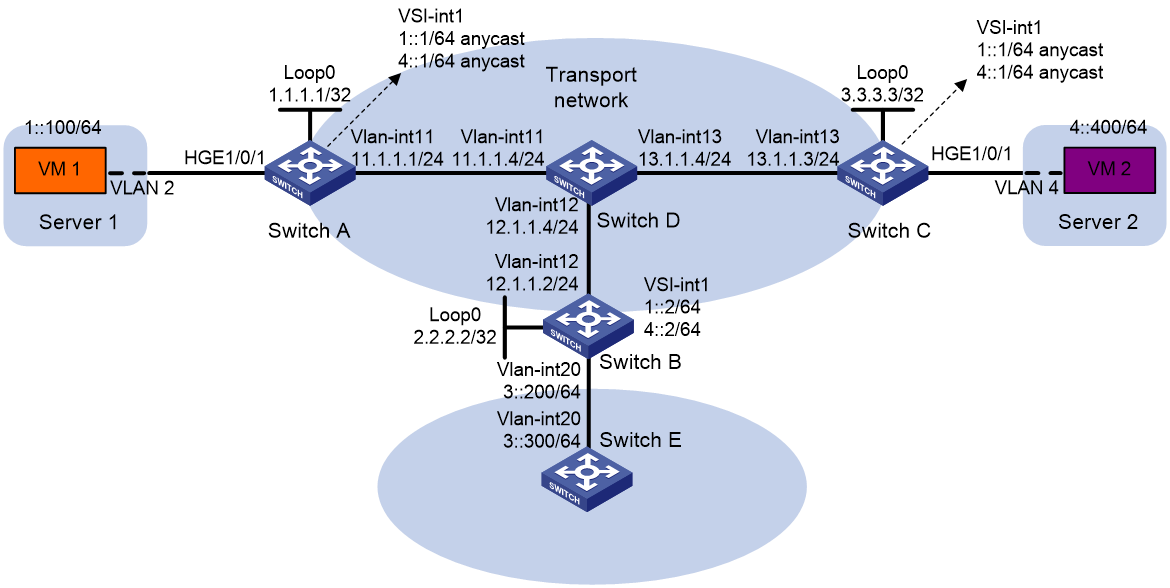
As shown in Figure 10:
· Configure VXLAN 10 and VXLAN 20 as unicast-mode VXLANs on Switch A, Switch B, and Switch C to provide connectivity for the VMs across the network sites.
· Manually establish VXLAN tunnels and assign the tunnels to the VXLANs.
· Configure distributed VXLAN IP gateways on Switch A and Switch C to forward traffic between the VXLANs.
· Configure Switch B as a border gateway to forward traffic between the VXLANs and the WAN connected to Switch E.
Procedure
|
|
IMPORTANT: By default, interfaces on the device are disabled (in ADM or Administratively Down state). To have an interface operate, you must use the undo shutdown command to enable that interface. By default, interfaces on the device operate in Layer 3 mode. In this example, you must use the port link-mode command to configure the interfaces that host Ethernet service instances to operate in Layer 2 mode. |
1. On VM 1 and VM 2, specify 1::1 and 4::1 as the gateway address, respectively. (Details not shown.)
2. Configure IP addresses and unicast routing settings:
# Assign IP addresses to interfaces, as shown in Figure 10. (Details not shown.)
# Configure OSPF on all transport network switches (Switches A through D). (Details not shown.)
# Configure OSPFv3 to advertise routes to networks 1::/64, 4::/64, and 3::/64 on Switch B and Switch E. (Details not shown.)
3. Configure Switch A:
# Enable L2VPN.
<SwitchA> system-view
[SwitchA] l2vpn enable
# Create VSI vpna and VXLAN 10.
[SwitchA] vsi vpna
[SwitchA-vsi-vpna] vxlan 10
[SwitchA-vsi-vpna-vxlan-10] quit
[SwitchA-vsi-vpna] quit
# Create VSI vpnb and VXLAN 20.
[SwitchA] vsi vpnb
[SwitchA-vsi-vpnb] vxlan 20
[SwitchA-vsi-vpnb-vxlan-20] quit
[SwitchA-vsi-vpnb] quit
# Assign an IP address to Loopback 0. The IP address will be used as the source IP address of the VXLAN tunnels to Switch B and Switch C.
[SwitchA] interface loopback 0
[SwitchA-Loopback0] ip address 1.1.1.1 255.255.255.255
[SwitchA-Loopback0] quit
# Create a VXLAN tunnel to Switch B. The tunnel interface name is Tunnel 1.
[SwitchA] interface tunnel 1 mode vxlan
[SwitchA-Tunnel1] source 1.1.1.1
[SwitchA-Tunnel1] destination 2.2.2.2
[SwitchA-Tunnel1] quit
# Create a VXLAN tunnel to Switch C. The tunnel interface name is Tunnel 2.
[SwitchA] interface tunnel 2 mode vxlan
[SwitchA-Tunnel2] source 1.1.1.1
[SwitchA-Tunnel2] destination 3.3.3.3
[SwitchA-Tunnel2] quit
# Assign Tunnel 1 and Tunnel 2 to VXLAN 10.
[SwitchA] vsi vpna
[SwitchA-vsi-vpna] vxlan 10
[SwitchA-vsi-vpna-vxlan-10] tunnel 1
[SwitchA-vsi-vpna-vxlan-10] tunnel 2
[SwitchA-vsi-vpna-vxlan-10] quit
[SwitchA-vsi-vpna] quit
# Assign Tunnel 1 and Tunnel 2 to VXLAN 20.
[SwitchA] vsi vpnb
[SwitchA-vsi-vpnb] vxlan 20
[SwitchA-vsi-vpnb-vxlan-20] tunnel 1
[SwitchA-vsi-vpnb-vxlan-20] tunnel 2
[SwitchA-vsi-vpnb-vxlan-20] quit
[SwitchA-vsi-vpnb] quit
# On HundredGigE 1/0/1, create Ethernet service instance 1000 to match VLAN 2.
[SwitchA] interface hundredgige 1/0/1
[SwitchA-HundredGigE1/0/1] port link-type trunk
[SwitchA-HundredGigE1/0/1] port trunk permit vlan 2
[SwitchA-HundredGigE1/0/1] service-instance 1000
[SwitchA-HundredGigE1/0/1-srv1000] encapsulation s-vid 2
# Map Ethernet service instance 1000 to VSI vpna.
[SwitchA-HundredGigE1/0/1-srv1000] xconnect vsi vpna
[SwitchA-HundredGigE1/0/1-srv1000] quit
[SwitchA-HundredGigE1/0/1] quit
# Create VSI-interface 1 and assign the interface two IPv6 anycast addresses. The IP addresses will be used as gateway addresses for VXLAN 10 and VXLAN 20.
[SwitchA] interface vsi-interface 1
[SwitchA-Vsi-interface1] ipv6 address 1::1/64 anycast
[SwitchA-Vsi-interface1] ipv6 address 4::1/64 anycast
# Specify VSI-interface 1 as a distributed gateway and enable local ND proxy on the interface.
[SwitchA-Vsi-interface1] distributed-gateway local
[SwitchA-Vsi-interface1] local-proxy-nd enable
[SwitchA-Vsi-interface1] quit
# Enable dynamic ND entry synchronization for distributed VXLAN IP gateways.
[SwitchA] ipv6 nd distributed-gateway dynamic-entry synchronize
# Specify VSI-interface 1 as the gateway interface for VSI vpna. Assign subnet 1::1/64 to the VSI.
[SwitchA] vsi vpna
[SwitchA-vsi-vpna] gateway vsi-interface 1
[SwitchA-vsi-vpna] gateway subnet 1::1 64
[SwitchA-vsi-vpna] quit
# Specify VSI-interface 1 as the gateway interface for VSI vpnb. Assign subnet 4::1/64 to the VSI.
[SwitchA] vsi vpnb
[SwitchA-vsi-vpnb] gateway vsi-interface 1
[SwitchA-vsi-vpnb] gateway subnet 4::1 64
[SwitchA-vsi-vpnb] quit
# Configure an IPv6 static route. Set the destination address to 3::/64 and the next hop to 1::2.
[SwitchA] ipv6 route-static 3:: 64 1::2
4. Configure Switch B:
# Enable L2VPN.
<SwitchB> system-view
[SwitchB] l2vpn enable
# Create VSI vpna and VXLAN 10.
[SwitchB] vsi vpna
[SwitchB-vsi-vpna] vxlan 10
[SwitchB-vsi-vpna-vxlan-10] quit
[SwitchB-vsi-vpna] quit
# Create VSI vpnb and VXLAN 20.
[SwitchB] vsi vpnb
[SwitchB-vsi-vpnb] vxlan 20
[SwitchB-vsi-vpnb-vxlan-20] quit
[SwitchB-vsi-vpnb] quit
# Assign an IP address to Loopback 0. The IP address will be used as the source IP address of the VXLAN tunnels to Switch A and Switch C.
[SwitchB] interface loopback 0
[SwitchB-Loopback0] ip address 2.2.2.2 255.255.255.255
[SwitchB-Loopback0] quit
# Create a VXLAN tunnel to Switch A. The tunnel interface name is Tunnel 2.
[SwitchB] interface tunnel 2 mode vxlan
[SwitchB-Tunnel2] source 2.2.2.2
[SwitchB-Tunnel2] destination 1.1.1.1
[SwitchB-Tunnel2] quit
# Create a VXLAN tunnel to Switch C. The tunnel interface name is Tunnel 3.
[SwitchB] interface tunnel 3 mode vxlan
[SwitchB-Tunnel3] source 2.2.2.2
[SwitchB-Tunnel3] destination 3.3.3.3
[SwitchB-Tunnel3] quit
# Assign Tunnel 2 and Tunnel 3 to VXLAN 10.
[SwitchB] vsi vpna
[SwitchB-vsi-vpna] vxlan 10
[SwitchB-vsi-vpna-vxlan-10] tunnel 2
[SwitchB-vsi-vpna-vxlan-10] tunnel 3
[SwitchB-vsi-vpna-vxlan-10] quit
[SwitchB-vsi-vpna] quit
# Assign Tunnel 2 and Tunnel 3 to VXLAN 20.
[SwitchB] vsi vpnb
[SwitchB-vsi-vpnb] vxlan 20
[SwitchB-vsi-vpnb-vxlan-20] tunnel 2
[SwitchB-vsi-vpnb-vxlan-20] tunnel 3
[SwitchB-vsi-vpnb-vxlan-20] quit
[SwitchB-vsi-vpnb] quit
# Create VSI-interface 1 and assign the interface IPv6 addresses.
[SwitchB] interface vsi-interface 1
[SwitchB-Vsi-interface1] ipv6 address 1::2/64
[SwitchB-Vsi-interface1] ipv6 address 4::2/64
[SwitchB-Vsi-interface1] quit
# Specify VSI-interface 1 as the gateway interface for VSI vpna.
[SwitchB] vsi vpna
[SwitchB-vsi-vpna] gateway vsi-interface 1
[SwitchB-vsi-vpna] quit
# Specify VSI-interface 1 as the gateway interface for VSI vpnb.
[SwitchB] vsi vpnb
[SwitchB-vsi-vpnb] gateway vsi-interface 1
[SwitchB-vsi-vpnb] quit
5. Configure Switch C:
# Enable L2VPN.
<SwitchC> system-view
[SwitchC] l2vpn enable
# Create VSI vpna and VXLAN 10.
[SwitchC] vsi vpna
[SwitchC-vsi-vpna] vxlan 10
[SwitchC-vsi-vpna-vxlan-10] quit
[SwitchC-vsi-vpna] quit
# Create VSI vpnb and VXLAN 20.
[SwitchC] vsi vpnb
[SwitchC-vsi-vpnb] vxlan 20
[SwitchC-vsi-vpnb-vxlan-20] quit
[SwitchC-vsi-vpnb] quit
# Assign an IP address to Loopback 0. The IP address will be used as the source IP address of the VXLAN tunnels to Switch A and Switch B.
[SwitchC] interface loopback 0
[SwitchC-Loopback0] ip address 3.3.3.3 255.255.255.255
[SwitchC-Loopback0] quit
# Create a VXLAN tunnel to Switch A. The tunnel interface name is Tunnel 1.
[SwitchC] interface tunnel 1 mode vxlan
[SwitchC-Tunnel1] source 3.3.3.3
[SwitchC-Tunnel1] destination 1.1.1.1
[SwitchC-Tunnel1] quit
# Create a VXLAN tunnel to Switch B. The tunnel interface name is Tunnel 3.
[SwitchC] interface tunnel 3 mode vxlan
[SwitchC-Tunnel3] source 3.3.3.3
[SwitchC-Tunnel3] destination 2.2.2.2
[SwitchC-Tunnel3] quit
# Assign Tunnel 1 and Tunnel 3 to VXLAN 10.
[SwitchC] vsi vpna
[SwitchC-vsi-vpna] vxlan 10
[SwitchC-vsi-vpna-vxlan-10] tunnel 1
[SwitchC-vsi-vpna-vxlan-10] tunnel 3
[SwitchC-vsi-vpna-vxlan-10] quit
[SwitchC-vsi-vpna] quit
# Assign Tunnel 1 and Tunnel 3 to VXLAN 20.
[SwitchC] vsi vpnb
[SwitchC-vsi-vpnb] vxlan 20
[SwitchC-vsi-vpnb-vxlan-20] tunnel 1
[SwitchC-vsi-vpnb-vxlan-20] tunnel 3
[SwitchC-vsi-vpnb-vxlan-20] quit
[SwitchC-vsi-vpnb] quit
# On HundredGigE 1/0/1, create Ethernet service instance 1000 to match VLAN 4.
[SwitchC] interface hundredgige 1/0/1
[SwitchC-HundredGigE1/0/1] port link-type trunk
[SwitchC-HundredGigE1/0/1] port trunk permit vlan 4
[SwitchC-HundredGigE1/0/1] service-instance 1000
[SwitchC-HundredGigE1/0/1-srv1000] encapsulation s-vid 4
# Map Ethernet service instance 1000 to VSI vpnb.
[SwitchC-HundredGigE1/0/1-srv1000] xconnect vsi vpnb
[SwitchC-HundredGigE1/0/1-srv1000] quit
[SwitchC-HundredGigE1/0/1] quit
# Create VSI-interface 1 and assign the interface two IPv6 anycast addresses. The IP addresses will be used as gateway addresses for VXLAN 10 and VXLAN 20.
[SwitchC] interface vsi-interface 1
[SwitchC-Vsi-interface1] ipv6 address 1::1/64 anycast
[SwitchC-Vsi-interface1] ipv6 address 4::1/64 anycast
# Specify VSI-interface 1 as a distributed gateway and enable local ND proxy on the interface.
[SwitchC-Vsi-interface1] distributed-gateway local
[SwitchC-Vsi-interface1] local-proxy-nd enable
[SwitchC-Vsi-interface1] quit
# Enable dynamic ND entry synchronization for distributed VXLAN IP gateways.
[SwitchC] ipv6 nd distributed-gateway dynamic-entry synchronize
# Specify VSI-interface 1 as the gateway interface for VSI vpna. Assign subnet 1::1/64 to the VSI.
[SwitchC] vsi vpna
[SwitchC-vsi-vpna] gateway vsi-interface 1
[SwitchC-vsi-vpna] gateway subnet 1::1 64
[SwitchC-vsi-vpna] quit
# Specify VSI-interface 1 as the gateway interface for VSI vpnb. Assign subnet 4::1/64 to the VSI.
[SwitchC] vsi vpnb
[SwitchC-vsi-vpnb] gateway vsi-interface 1
[SwitchC-vsi-vpnb] gateway subnet 4::1 64
[SwitchC-vsi-vpnb] quit
# Configure an IPv6 static route. Set the destination address to 3::/64 and the next hop to 4::2.
[SwitchC] ipv6 route-static 3:: 64 4::2
Verifying the configuration
1. Verify the distributed VXLAN IP gateway settings on Switch A:
# Verify that the VXLAN tunnel interfaces are up on Switch A.
[SwitchA] display interface tunnel 2
Tunnel2
Current state: UP
Line protocol state: UP
Description: Tunnel2 Interface
Bandwidth: 64 kbps
Maximum transmission unit: 64000
Internet protocol processing: Disabled
Last clearing of counters: Never
Tunnel source 1.1.1.1, destination 3.3.3.3
Tunnel protocol/transport UDP_VXLAN/IP
Last 300 seconds input rate: 0 bytes/sec, 0 bits/sec, 0 packets/sec
Last 300 seconds output rate: 0 bytes/sec, 0 bits/sec, 0 packets/sec
Input: 0 packets, 0 bytes, 0 drops
Output: 0 packets, 0 bytes, 0 drops
# Verify that VSI-interface 1 is up.
[SwitchA] display interface vsi-interface 1
Vsi-interface1
Current state: UP
Line protocol state: UP
Description: Vsi-interface1 Interface
Bandwidth: 1000000 kbps
Maximum transmission unit: 1444
Internet protocol processing: Disabled
IP packet frame type: Ethernet II, hardware address: 0011-2200-0102
IPv6 packet frame type: Ethernet II, hardware address: 0011-2200-0102
Physical: Unknown, baudrate: 1000000 kbps
Last clearing of counters: Never
# Verify that the VXLAN tunnels have been assigned to VXLAN 10 and VXLAN 20, and VSI-interface 1 is the gateway interface for VSIs vpna and vpnb.
[SwitchA] display l2vpn vsi verbose
VSI Name: vpna
VSI Index : 0
VSI State : Up
MTU : -
Diffserv Mode : -
Bandwidth : Unlimited
Broadcast Restrain : Unlimited
Multicast Restrain : Unlimited
Unknown Unicast Restrain: Unlimited
MAC Learning : Enabled
MAC Table Limit : -
MAC Learning rate : -
Drop Unknown : -
PW Redundancy Mode : Slave
Flooding : Enabled
ESI : 0000.0000.0000.0000.0000
Redundancy Mode : All-active
Statistics : Disabled
Gateway Interface : VSI-interface 1
VXLAN ID : 10
Tunnels:
Tunnel Name Link ID State Type Flood proxy
Tunnel1 0x5000001 Up Manual Disabled
Tunnel2 0x5000002 Up Manual Disabled
ACs:
AC Link ID State Type
HGE1/0/1 srv1000 0 Up
Statistics: Disabled
VSI Name: vpnb
VSI Index : 0
VSI State : Up
MTU : -
Diffserv Mode : -
Bandwidth : Unlimited
Broadcast Restrain : Unlimited
Multicast Restrain : Unlimited
Unknown Unicast Restrain: Unlimited
MAC Learning : Enabled
MAC Table Limit : -
MAC Learning rate : -
Drop Unknown : -
PW Redundancy Mode : Slave
Flooding : Enabled
ESI : 0000.0000.0000.0000.0000
Redundancy Mode : All-active
Statistics : Disabled
Gateway Interface : VSI-interface 1
VXLAN ID : 20
Tunnels:
Tunnel Name Link ID State Type Flood proxy
Tunnel1 0x5000001 Up Manual Disabled
Tunnel2 0x5000002 Up Manual Disabled
# Verify that Switch A has created neighbor entries for the VMs.
[SwitchA] display ipv6 neighbors all
Type: S-Static D-Dynamic O-Openflow R-Rule I-Invalid
IPv6 address Link layer VID Interface State T Age
1::2 3c8c-400d-867a 0 Tunnel1 STALE D 7
1::100 0001-0000-0047 0 0 STALE D 22
4::400 0002-0000-0047 1 Tunnel2 REACH D 5
FE80::201:FF:FE00:47 0001-0000-0047 0 Tunnel1 REACH D 30
FE80::202:FF:FE00:0 0002-0000-0000 1 Tunnel1 REACH D 27
FE80::202:FF:FE00:47 0002-0000-0047 0 0 DELAY D 5
# Verify that Switch A has created FIB entries for the VMs.
[SwitchA] display ipv6 fib 4::400
Destination count: 1 FIB entry count: 1
Flag:
U:Usable G:Gateway H:Host B:Blackhole D:Dynamic S:Static
R:Relay F:FRR
Destination: 4::400 Prefix length: 128
Nexthop : 4::400 Flags: UH
Time stamp : 0x2c Label: Null
Interface : Tunnel2 Token: Invalid
[SwitchA] display ipv6 fib 3::300
Destination count: 1 FIB entry count: 1
Flag:
U:Usable G:Gateway H:Host B:Blackhole D:Dynamic S:Static
R:Relay F:FRR
Destination: 3:: Prefix length: 40
Nexthop : 1::2 Flags: USGR
Time stamp : 0x23 Label: Null
Interface : Tunnel1 Token: Invalid
2. Verify the configuration on the border gateway Switch B:
# Verify that the VXLAN tunnel interfaces are up on Switch B.
[SwitchB] display interface tunnel 2
Tunnel2
Current state: UP
Line protocol state: UP
Description: Tunnel2 Interface
Bandwidth: 64 kbps
Maximum transmission unit: 64000
Internet protocol processing: Disabled
Last clearing of counters: Never
Tunnel source 2.2.2.2, destination 1.1.1.1
Tunnel protocol/transport UDP_VXLAN/IP
Last 300 seconds input rate: 0 bytes/sec, 0 bits/sec, 0 packets/sec
Last 300 seconds output rate: 0 bytes/sec, 0 bits/sec, 0 packets/sec
Input: 0 packets, 0 bytes, 0 drops
Output: 0 packets, 0 bytes, 0 drops
# Verify that VSI-interface 1 is up.
[SwitchB] display interface vsi-interface 1
Vsi-interface1
Current state: UP
Line protocol state: UP
Description: Vsi-interface1 Interface
Bandwidth: 1000000 kbps
Maximum transmission unit: 1444
Internet protocol processing: Disabled
IP packet frame type: Ethernet II, hardware address: 0011-2200-0102
IPv6 packet frame type: Ethernet II, hardware address: 0011-2200-0102
Physical: Unknown, baudrate: 1000000 kbps
Last clearing of counters: Never
# Verify that the VXLAN tunnels have been assigned to VXLAN 10, and VSI-interface 1 is the gateway interface for VSI vpna.
[SwitchB] display l2vpn vsi name vpna verbose
VSI Name: vpna
VSI Index : 0
VSI State : Up
MTU : -
Diffserv Mode : -
Bandwidth : Unlimited
Broadcast Restrain : Unlimited
Multicast Restrain : Unlimited
Unknown Unicast Restrain: Unlimited
MAC Learning : Enabled
MAC Table Limit : -
MAC Learning rate : -
Drop Unknown : -
PW Redundancy Mode : Slave
Flooding : Enabled
ESI : 0000.0000.0000.0000.0000
Redundancy Mode : All-active
Statistics : Disabled
Gateway interface : VSI-interface 1
VXLAN ID : 10
Tunnels:
Tunnel Name Link ID State Type Flood proxy
Tunnel1 0x5000001 Up Manual Disabled
Tunnel2 0x5000002 Up Manual Disabled
# Verify that Switch B has created neighbor entries for the VMs.
[SwitchB] display ipv6 neighbors all
Type: S-Static D-Dynamic O-Openflow R-Rule I-Invalid
IPv6 address Link layer VID Interface State T Age
3::300 0003-0000-0047 20 Vlan20 DELAY D 3
FE80::203:FF:FE00:47 0003-0000-0047 20 Vlan20 STALE D 222
1::100 0001-0000-0047 0 Tunnel2 STALE D 232
4::400 0002-0000-0047 1 Tunnel3 REACH D 3
FE80::201:FF:FE00:0 0001-0000-0000 0 Tunnel2 STALE D 237
FE80::201:FF:FE00:47 0001-0000-0047 20 Vlan20 STALE D 222
FE80::202:FF:FE00:0 0002-0000-0000 1 Tunnel3 STALE D 345
# Verify that Switch B has created FIB entries for the VMs.
[SwitchB] display ipv6 fib 1::100
Destination count: 1 FIB entry count: 1
Flag:
U:Usable G:Gateway H:Host B:Blackhole D:Dynamic S:Static
R:Relay F:FRR
Destination: 1::100 Prefix length: 128
Nexthop : 1::100 Flags: UH
Time stamp : 0x21 Label: Null
Interface : Tunnel2 Token: Invalid
[SwitchB] display ipv6 fib 4::400
Destination count: 1 FIB entry count: 1
Flag:
U:Usable G:Gateway H:Host B:Blackhole D:Dynamic S:Static
R:Relay F:FRR
Destination: 4:: Prefix length: 64
Nexthop : :: Flags: U
Time stamp : 0x19 Label: Null
Interface : Tunnel3 Token: Invalid
3. Verify that the network connectivity for the VMs meets the network requirements:
# Verify that VM 1 and VM 2 can ping each other. (Details not shown.)
# Verify that VM 1, VM 2, and VLAN-interface 20 (3::300) on Switch E can ping each other. (Details not shown.)
Example: Configuring VXLAN M-LAG with a direct peer link
Network configuration
As shown in Figure 11, perform the following tasks to make sure the VMs can communicate with one another:
· Configure Switch A, Switch B, and Switch C as distributed VXLAN IP gateways.
· Configure VXLAN 10 and VXLAN 20 on Switch A, Switch B, and Switch C.
· Configure VXLAN M-LAG on Switch A and Switch B to virtualize them into one device. The switches use an Ethernet aggregate link as the peer link.
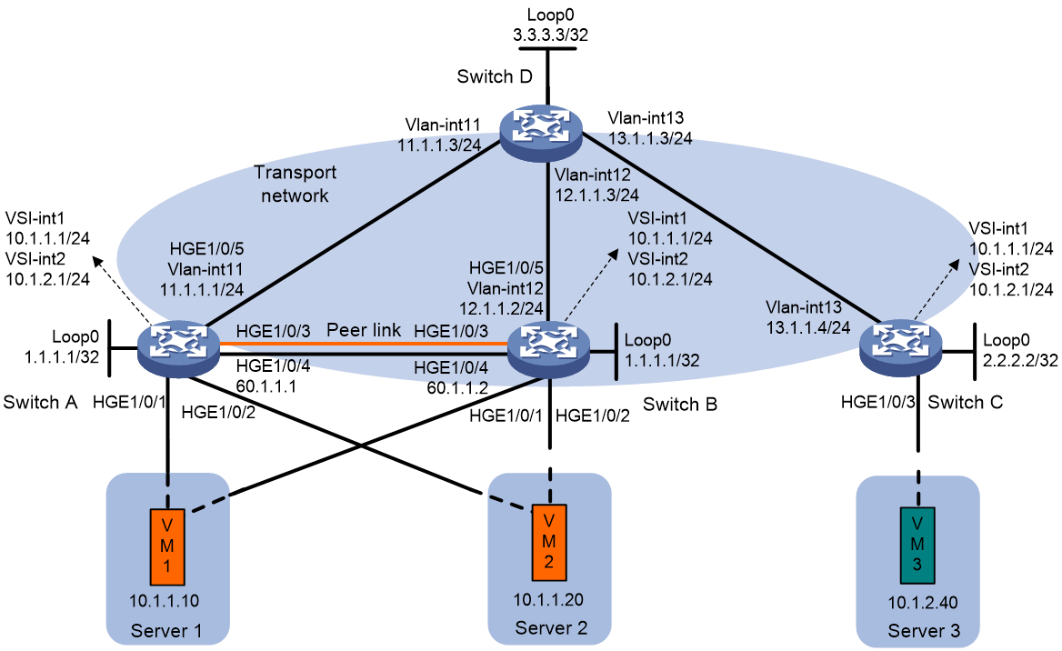
Procedure
|
|
IMPORTANT: By default, interfaces on the device are disabled (in ADM or Administratively Down state). To have an interface operate, you must use the undo shutdown command to enable that interface. By default, interfaces on the device operate in Layer 3 mode. In this example, you must use the port link-mode command to configure the interfaces that host Ethernet service instances to operate in Layer 2 mode. |
1. On VM 1 and VM 2, specify 10.1.1.1 as the gateway address. On VM 3, specify 10.1.2.1 as the gateway address. (Details not shown.)
2. Configure IP addresses and unicast routing settings:
# Assign IP addresses to interfaces (including loopback interfaces), as shown in Figure 11. (Details not shown.)
# Configure OSPF on all transport network switches (Switches A through D) for them to reach one another. (Details not shown.)
3. Configure Switch A:
# Enable L2VPN.
<SwitchA> system-view
[SwitchA] l2vpn enable
# Choose one of the following frame match criterion creation methods for dynamic ACs:
¡ Enable the device to create frame match criteria based on VXLAN IDs for the dynamic ACs on the peer link.
[SwitchA] l2vpn m-lag peer-link ac-match-rule vxlan-mapping
¡ Use the default setting for dynamic ACs on the peer link to use frame match criteria identical to those of site-facing ACs.
# Configure M-LAG system settings.
[SwitchA] m-lag system-mac 0001-0001-0001
[SwitchA] m-lag system-number 1
[SwitchA] m-lag system-priority 10
[SwitchA] m-lag keepalive ip destination 60.1.1.2 source 60.1.1.1
[SwitchA] m-lag restore-delay 180
# Create Layer 2 dynamic aggregate interface Bridge-Aggregation 3.
[SwitchA] interface bridge-aggregation 3
[SwitchA-Bridge-Aggregation3] link-aggregation mode dynamic
[SwitchA-Bridge-Aggregation3] quit
# Assign HundredGigE 1/0/3 to link aggregation group 3.
[SwitchA] interface hundredgige 1/0/3
[SwitchA-HundredGigE1/0/3] port link-aggregation group 3
[SwitchA-HundredGigE1/0/3] quit
# Specify Bridge-Aggregation 3 as the peer-link interface.
[SwitchA] interface bridge-aggregation 3
[SwitchA-Bridge-Aggregation3] port m-lag peer-link 1
[SwitchA-Bridge-Aggregation3] quit
# Create Layer 2 dynamic aggregate interface Bridge-Aggregation 4.
[SwitchA] interface bridge-aggregation 4
[SwitchA-Bridge-Aggregation4] link-aggregation mode dynamic
[SwitchA-Bridge-Aggregation4] quit
# Assign HundredGigE 1/0/1 to link aggregation group 4.
[SwitchA] interface hundredgige 1/0/1
[SwitchA-HundredGigE1/0/1] port link-aggregation group 4
[SwitchA-HundredGigE1/0/1] quit
# Create Layer 2 dynamic aggregate interface Bridge-Aggregation 5.
[SwitchA] interface bridge-aggregation 5
[SwitchA-Bridge-Aggregation5] link-aggregation mode dynamic
[SwitchA-Bridge-Aggregation5] quit
# Assign HundredGigE 1/0/2 to link aggregation group 5.
[SwitchA] interface hundredgige 1/0/2
[SwitchA-HundredGigE1/0/2] port link-aggregation group 5
[SwitchA-HundredGigE1/0/2] quit
# Create VSI vpna and VXLAN 10.
[SwitchA] vsi vpna
[SwitchA-vsi-vpna] vxlan 10
[SwitchA-vsi-vpna-vxlan-10] quit
[SwitchA-vsi-vpna] quit
# Create VSI vpnb and VXLAN 20.
[SwitchA] vsi vpnb
[SwitchA-vsi-vpnb] vxlan 20
[SwitchA-vsi-vpnb-vxlan-20] quit
[SwitchA-vsi-vpnb] quit
# Assign an IP address to Loopback 0. The IP address will be used as the source IP address of the VXLAN tunnel to Switch C.
[SwitchA] interface loopback 0
[SwitchA-Loopback0] ip address 1.1.1.1 255.255.255.255
[SwitchA-Loopback0] quit
# Create a VXLAN tunnel to Switch C. The tunnel interface name is Tunnel 1.
[SwitchA] interface tunnel 1 mode vxlan
[SwitchA-Tunnel1] source 1.1.1.1
[SwitchA-Tunnel1] destination 2.2.2.2
[SwitchA-Tunnel1] quit
# Assign Tunnel 1 to VXLAN 10.
[SwitchA] vsi vpna
[SwitchA-vsi-vpna] vxlan 10
[SwitchA-vsi-vpna-vxlan-10] tunnel 1
[SwitchA-vsi-vpna-vxlan-10] quit
[SwitchA-vsi-vpna] quit
# Assign Tunnel 1 to VXLAN 20.
[SwitchA] vsi vpnb
[SwitchA-vsi-vpnb] vxlan 20
[SwitchA-vsi-vpnb-vxlan-20] tunnel 1
[SwitchA-vsi-vpnb-vxlan-20] quit
[SwitchA-vsi-vpnb] quit
# On Bridge-Aggregation 4, create Ethernet service instance 1000 to match VLAN 1.
[SwitchA] interface bridge-aggregation 4
[SwitchA-Bridge-Aggregation4] port link-type trunk
[SwitchA-Bridge-Aggregation4] port trunk permit vlan 1
[SwitchA-Bridge-Aggregation4] service-instance 1000
[SwitchA-Bridge-Aggregation4-srv1000] encapsulation s-vid 1
# Map Ethernet service instance 1000 to VSI vpna.
[SwitchA-Bridge-Aggregation10-srv1000] xconnect vsi vpna
[SwitchA-Bridge-Aggregation10-srv1000] quit
# On Bridge-Aggregation 5, create Ethernet service instance 1000 to match VLAN 2.
[SwitchA] interface bridge-aggregation 5
[SwitchA-Bridge-Aggregation5] port link-type trunk
[SwitchA-Bridge-Aggregation5] port trunk permit vlan 2
[SwitchA-Bridge-Aggregation5] service-instance 1000
[SwitchA-Bridge-Aggregation5-srv1000] encapsulation s-vid 2
# Map Ethernet service instance 1000 to VSI vpna.
[SwitchA-Bridge-Aggregation5-srv1000] xconnect vsi vpna
[SwitchA-Bridge-Aggregation5-srv1000] quit
# Create VSI-interface 1 and assign the interface an IP address and a MAC address. The IP address will be used as the gateway address for VXLAN 10.
[SwitchA] interface vsi-interface 1
[SwitchA-Vsi-interface1] ip address 10.1.1.1 255.255.255.0
[SwitchA-Vsi-interface1] mac-address 1-1-1
# Specify VSI-interface 1 as a distributed gateway.
[SwitchA-Vsi-interface1] distributed-gateway local
[SwitchA-Vsi-interface1] quit
# Create VSI-interface 2 and assign the interface an IP address and a MAC address. The IP address will be used as the gateway address for VXLAN 20.
[SwitchA] interface vsi-interface 2
[SwitchA-Vsi-interface2] ip address 10.1.2.1 255.255.255.0
[SwitchA-Vsi-interface2] mac-address 2-2-2
# Specify VSI-interface 2 as a distributed gateway.
[SwitchA-Vsi-interface2] distributed-gateway local
[SwitchA-Vsi-interface2] quit
# Enable dynamic ARP entry synchronization for distributed VXLAN IP gateways.
[SwitchA] arp distributed-gateway dynamic-entry synchronize
# Specify VSI-interface 1 as the gateway interface for VSI vpna.
[SwitchA] vsi vpna
[SwitchA-vsi-vpna] gateway vsi-interface 1
[SwitchA-vsi-vpna] quit
# Specify VSI-interface 2 as the gateway interface for VSI vpnb.
[SwitchA] vsi vpnb
[SwitchA-vsi-vpnb] gateway vsi-interface 2
[SwitchA-vsi-vpnb] quit
# Exclude the interfaces used by VXLAN from the shutdown action by M-LAG MAD.
[SwitchA] m-lag mad exclude interface loopback 0
[SwitchA] m-lag mad exclude interface hundredgige 1/0/4
[SwitchA] m-lag mad exclude interface vsi-interface 1
[SwitchA] m-lag mad exclude interface vsi-interface 2
[SwitchA] m-lag mad exclude interface vlan-interface 11
4. Configure Switch B:
# Enable L2VPN.
<SwitchB> system-view
[SwitchB] l2vpn enable
# Choose one of the following frame match criterion creation methods for dynamic ACs:
¡ Enable the device to create frame match criteria based on VXLAN IDs for the dynamic ACs on the peer link.
[SwitchB] l2vpn m-lag peer-link ac-match-rule vxlan-mapping
¡ Use the default setting for dynamic ACs on the peer link to use frame match criteria identical to those of site-facing ACs.
# Configure M-LAG system settings.
[SwitchB] m-lag system-mac 0001-0001-0001
[SwitchB] m-lag system-number 2
[SwitchB] m-lag system-priority 10
[SwitchB] m-lag keepalive ip destination 60.1.1.1 source 60.1.1.2
[SwitchB] m-lag restore-delay 180
# Create Layer 2 dynamic aggregate interface Bridge-Aggregation 3.
[SwitchB] interface bridge-aggregation 3
[SwitchB-Bridge-Aggregation3] link-aggregation mode dynamic
[SwitchB-Bridge-Aggregation3] quit
# Assign HundredGigE 1/0/3 to link aggregation group 3.
[SwitchB] interface hundredgige 1/0/3
[SwitchB-HundredGigE1/0/3] port link-aggregation group 3
[SwitchB-HundredGigE1/0/3] quit
# Specify Bridge-Aggregation 3 as the peer-link interface.
[SwitchB] interface bridge-aggregation 3
[SwitchB-Bridge-Aggregation3] port m-lag peer-link 1
[SwitchB-Bridge-Aggregation3] quit
# Create Layer 2 dynamic aggregate interface Bridge-Aggregation 4.
[SwitchB] interface bridge-aggregation 4
[SwitchB-Bridge-Aggregation4] link-aggregation mode dynamic
[SwitchB-Bridge-Aggregation4] quit
# Assign HundredGigE 1/0/1 to link aggregation group 4.
[SwitchB] interface hundredgige 1/0/1
[SwitchB-HundredGigE1/0/1] port link-aggregation group 4
[SwitchB-HundredGigE1/0/1] quit
# Create Layer 2 dynamic aggregate interface Bridge-Aggregation 5.
[SwitchB] interface bridge-aggregation 5
[SwitchB-Bridge-Aggregation5] link-aggregation mode dynamic
[SwitchB-Bridge-Aggregation5] quit
# Assign HundredGigE 1/0/2 to link aggregation group 5.
[SwitchB] interface hundredgige 1/0/2
[SwitchB-HundredGigE1/0/2] port link-aggregation group 5
[SwitchB-HundredGigE1/0/2] quit
# Create VSI vpna and VXLAN 10.
[SwitchB] vsi vpna
[SwitchB-vsi-vpna] vxlan 10
[SwitchB-vsi-vpna-vxlan-10] quit
[SwitchB-vsi-vpna] quit
# Create VSI vpnb and VXLAN 20.
[SwitchB] vsi vpnb
[SwitchB-vsi-vpnb] vxlan 20
[SwitchB-vsi-vpnb-vxlan-20] quit
[SwitchB-vsi-vpnb] quit
# Assign an IP address to Loopback 0. The IP address will be used as the source IP address of the VXLAN tunnel to Switch C.
[SwitchB] interface loopback 0
[SwitchB-Loopback0] ip address 1.1.1.1 255.255.255.255
[SwitchB-Loopback0] quit
# Create a VXLAN tunnel to Switch C. The tunnel interface name is Tunnel 1.
[SwitchB] interface tunnel 1 mode vxlan
[SwitchB-Tunnel1] source 1.1.1.1
[SwitchB-Tunnel1] destination 2.2.2.2
[SwitchB-Tunnel1] quit
# Assign Tunnel 1 to VXLAN 10.
[SwitchB] vsi vpna
[SwitchB-vsi-vpna] vxlan 10
[SwitchB-vsi-vpna-vxlan-10] tunnel 1
[SwitchB-vsi-vpna-vxlan-10] quit
[SwitchB-vsi-vpna] quit
# Assign Tunnel 1 to VXLAN 20.
[SwitchB] vsi vpnb
[SwitchB-vsi-vpnb] vxlan 20
[SwitchB-vsi-vpnb-vxlan-20] tunnel 1
[SwitchB-vsi-vpnb-vxlan-20] quit
[SwitchB-vsi-vpnb] quit
# On Bridge-Aggregation 4, create Ethernet service instance 1000 to match VLAN 1.
[SwitchB] interface bridge-aggregation 4
[SwitchB-Bridge-Aggregation4] port link-type trunk
[SwitchB-Bridge-Aggregation4] port trunk permit vlan 1
[SwitchB-Bridge-Aggregation4] service-instance 1000
[SwitchB-Bridge-Aggregation4-srv1000] encapsulation s-vid 1
# Map Ethernet service instance 1000 to VSI vpna.
[SwitchB-Bridge-Aggregation10-srv1000] xconnect vsi vpna
[SwitchB-Bridge-Aggregation10-srv1000] quit
# On Bridge-Aggregation 5, create Ethernet service instance 1000 to match VLAN 2.
[SwitchB] interface bridge-aggregation 5
[SwitchB-Bridge-Aggregation5] port link-type trunk
[SwitchB-Bridge-Aggregation5] port trunk permit vlan 2
[SwitchB-Bridge-Aggregation5] service-instance 1000
[SwitchB-Bridge-Aggregation5-srv1000] encapsulation s-vid 2
# Map Ethernet service instance 1000 to VSI vpna.
[SwitchB-Bridge-Aggregation5-srv1000] xconnect vsi vpna
[SwitchB-Bridge-Aggregation5-srv1000] quit
# Create VSI-interface 1 and assign the interface an IP address and a MAC address. The IP address will be used as the gateway address for VXLAN 10.
[SwitchB] interface vsi-interface 1
[SwitchB-Vsi-interface1] ip address 10.1.1.1 255.255.255.0
[SwitchB-Vsi-interface1] mac-address 1-1-1
# Specify VSI-interface 1 as a distributed gateway.
[SwitchB-Vsi-interface1] distributed-gateway local
[SwitchB-Vsi-interface1] quit
# Create VSI-interface 2 and assign the interface an IP address and a MAC address. The IP address will be used as the gateway address for VXLAN 20.
[SwitchB] interface vsi-interface 2
[SwitchB-Vsi-interface2] ip address 10.1.2.1 255.255.255.0
[SwitchB-Vsi-interface2] mac-address 2-2-2
# Specify VSI-interface 2 as a distributed gateway.
[SwitchB-Vsi-interface2] distributed-gateway local
[SwitchB-Vsi-interface2] quit
# Enable dynamic ARP entry synchronization for distributed VXLAN IP gateways.
[SwitchB] arp distributed-gateway dynamic-entry synchronize
# Specify VSI-interface 1 as the gateway interface for VSI vpna.
[SwitchB] vsi vpna
[SwitchB-vsi-vpna] gateway vsi-interface 1
[SwitchB-vsi-vpna] quit
# Specify VSI-interface 2 as the gateway interface for VSI vpnb.
[SwitchB] vsi vpnb
[SwitchB-vsi-vpnb] gateway vsi-interface 2
[SwitchB-vsi-vpnb] quit
# Exclude the interfaces used by VXLAN from the shutdown action by M-LAG MAD.
[SwitchB] m-lag mad exclude interface loopback 0
[SwitchB] m-lag mad exclude interface hundredgige 1/0/4
[SwitchB] m-lag mad exclude interface vsi-interface 1
[SwitchB] m-lag mad exclude interface vsi-interface 2
[SwitchB] m-lag mad exclude interface vlan-interface 12
5. Configure Switch C:
# Enable L2VPN.
<SwitchC> system-view
[SwitchC] l2vpn enable
# Create VSI vpna and VXLAN 10.
[SwitchC] vsi vpna
[SwitchC-vsi-vpna] vxlan 10
[SwitchC-vsi-vpna-vxlan-10] quit
[SwitchC-vsi-vpna] quit
# Create VSI vpnb and VXLAN 20.
[SwitchC] vsi vpnb
[SwitchC-vsi-vpnb] vxlan 20
[SwitchC-vsi-vpnb-vxlan-20] quit
[SwitchC-vsi-vpnb] quit
# Assign an IP address to Loopback 0. The IP address will be used as the source IP address of the VXLAN tunnels to Switch A and Switch B.
[SwitchC] interface loopback 0
[SwitchC-Loopback0] ip address 2.2.2.2 255.255.255.255
[SwitchC-Loopback0] quit
# Create a VXLAN tunnel to Switch A and Switch B. The tunnel interface name is Tunnel 1.
[SwitchC] interface tunnel 1 mode vxlan
[SwitchC-Tunnel1] source 2.2.2.2
[SwitchC-Tunnel1] destination 1.1.1.1
[SwitchC-Tunnel1] quit
# Assign Tunnel 1 to VXLAN 10.
[SwitchC] vsi vpna
[SwitchC-vsi-vpna] vxlan 10
[SwitchC-vsi-vpna-vxlan-10] tunnel 1
[SwitchC-vsi-vpna-vxlan-10] quit
[SwitchC-vsi-vpna] quit
# Assign Tunnel 1 to VXLAN 20.
[SwitchC] vsi vpnb
[SwitchC-vsi-vpnb] vxlan 20
[SwitchC-vsi-vpnb-vxlan-20] tunnel 1
[SwitchC-vsi-vpnb-vxlan-20] quit
[SwitchC-vsi-vpnb] quit
# On HundredGigE 1/0/3, create Ethernet service instance 1000 to match VLAN 4.
[SwitchC] interface hundredgige 1/0/3
[SwitchC-HundredGigE1/0/3] port link-type trunk
[SwitchC-HundredGigE1/0/3] port trunk permit vlan 4
[SwitchC-HundredGigE1/0/3] service-instance 1000
[SwitchC-HundredGigE1/0/3-srv1000] encapsulation s-vid 4
# Map Ethernet service instance 1000 to VSI vpnb.
[SwitchC-HundredGigE1/0/3-srv1000] xconnect vsi vpnb
[SwitchC-HundredGigE1/0/3-srv1000] quit
[SwitchC-HundredGigE1/0/3] quit
# Create VSI-interface 1 and assign the interface an IP address and a MAC address. The IP address will be used as the gateway address for VXLAN 10.
[SwitchC] interface vsi-interface 1
[SwitchC-Vsi-interface1] ip address 10.1.1.1 255.255.255.0
[SwitchC-Vsi-interface1] mac-address 1-1-1
# Specify VSI-interface 1 as a distributed gateway and enable local proxy ARP on the interface.
[SwitchC-Vsi-interface1] distributed-gateway local
[SwitchC-Vsi-interface1] local-proxy-arp enable
[SwitchC-Vsi-interface1] quit
# Create VSI-interface 2 and assign the interface an IP address and a MAC address. The IP address will be used as the gateway address for VXLAN 20.
[SwitchC] interface vsi-interface 2
[SwitchC-Vsi-interface2] ip address 10.1.2.1 255.255.255.0
[SwitchC-Vsi-interface2] mac-address 2-2-2
# Specify VSI-interface 2 as a distributed gateway and enable local proxy ARP on the interface.
[SwitchC-Vsi-interface2] distributed-gateway local
[SwitchC-Vsi-interface2] local-proxy-arp enable
[SwitchC-Vsi-interface2] quit
# Enable dynamic ARP entry synchronization for distributed VXLAN IP gateways.
[SwitchC] arp distributed-gateway dynamic-entry synchronize
# Specify VSI-interface 1 as the gateway interface for VSI vpna.
[SwitchC] vsi vpna
[SwitchC-vsi-vpna] gateway vsi-interface 1
[SwitchC-vsi-vpna] quit
# Specify VSI-interface 2 as the gateway interface for VSI vpnb.
[SwitchC] vsi vpnb
[SwitchC-vsi-vpnb] gateway vsi-interface 2
[SwitchC-vsi-vpnb] quit
Verifying the configuration
1. Verify the M-LAG configuration on Switch A:
# Verify that the VXLAN tunnel to Switch C is up, and the tunnel source address is 1.1.1.1.
[SwitchA]display interface tunnel
Tunnel1
Current state: UP
Line protocol state: UP
Description: Tunnel1 Interface
Bandwidth: 64 kbps
Maximum transmission unit: 64000
Internet protocol processing: Disabled
Last clearing of counters: Never
Tunnel source 1.1.1.1, destination 2.2.2.2
Tunnel protocol/transport UDP_VXLAN/IP
Last 300 seconds input rate: 0 bytes/sec, 0 bits/sec, 0 packets/sec
Last 300 seconds output rate: 50506 bytes/sec, 404048 bits/sec, 295 packets/sec
Input: 4 packets, 240 bytes, 0 drops
Output: 257011 packets, 43395523 bytes, 0 drops
# Verify that ACs are automatically created on the peer link and assigned to VSIs.
¡ For dynamic ACs whose frame match criteria are generated based on VXLAN IDs:
[SwitchA] display l2vpn vsi verbose
VSI Name: vpna
VSI Index : 1
VSI State : Up
MTU : 1500
Diffserv Mode : -
Bandwidth : Unlimited
Broadcast Restrain : Unlimited
Multicast Restrain : Unlimited
Unknown Unicast Restrain: Unlimited
MAC Learning : Enabled
MAC Table Limit : -
MAC Learning rate : -
Drop Unknown : -
PW Redundancy Mode : Slave
Flooding : Enabled
ESI : 0000.0000.0000.0000.0000
Redundancy Mode : All-active
Statistics : Disabled
VXLAN ID : 10
Tunnels:
Tunnel Name Link ID State Type Flood proxy
Tunnel0 0x5000000 UP Auto Disabled
ACs:
AC Link ID State
BAGG3 srv1 0 Up
BAGG4 srv1000 1 Up
BAGG5 srv1000 2 Up
Statistics: Disabled
¡ For dynamic ACs whose frame match criteria are identical to those of site-facing ACs:
[SwitchA] display l2vpn vsi name vpna verbose
VSI Name: vpna
VSI Index : 0
VSI State : Up
MTU : 1500
Diffserv Mode : -
Bandwidth : Unlimited
Broadcast Restrain : Unlimited
Multicast Restrain : Unlimited
Unknown Unicast Restrain: Unlimited
MAC Learning : Enabled
MAC Table Limit : -
MAC Learning rate : -
Drop Unknown : -
PW Redundancy Mode : Slave
Flooding : Enabled
ESI : 0000.0000.0000.0000.0000
Redundancy Mode : All-active
Statistics : Disabled
Gateway Interface : VSI-interface 1
VXLAN ID : 10
Tunnels:
Tunnel Name Link ID State Type Flood proxy
Tunnel1 0x5000001 UP Manual Disabled
ACs:
AC Link ID State
Type
BAGG4 srv1000 0x0 Up Dynamic
(M-LAG)
BAGG3 srv1 0x1 Up Dynamic
(M-LAG)
BAGG5 srv1000 0x2 Up Dynamic
(M-LAG)
BAGG3 srv2 0x3 Up Dynamic
(M-LAG)
2. Verify the distributed VXLAN IP gateway settings on Switch C:
# Verify that the VXLAN tunnel to Switch A and Switch B is up.
[SwitchC]display interface tunnel
Tunnel1
Current state: UP
Line protocol state: UP
Description: Tunnel1 Interface
Bandwidth: 64 kbps
Maximum transmission unit: 64000
Internet protocol processing: Disabled
Last clearing of counters: Never
Tunnel source 2.2.2.2, destination 1.1.1.1
Tunnel protocol/transport UDP_VXLAN/IP
Last 300 seconds input rate: 0 bytes/sec, 0 bits/sec, 0 packets/sec
Last 300 seconds output rate: 0 bytes/sec, 0 bits/sec, 0 packets/sec
Input: 8 packets, 480 bytes, 0 drops
Output: 4 packets, 240 bytes, 0 drops
# Verify that the VXLAN tunnel has been assigned to the VXLANs, and that the VSI interfaces are the gateway interfaces of their respective VXLANs.
[SwitchC] dis l2vpn vsi verbose
VSI Name: vpna
VSI Index : 0
VSI State : Up
MTU : 1500
Diffserv Mode : -
Bandwidth : Unlimited
Broadcast Restrain : Unlimited
Multicast Restrain : Unlimited
Unknown Unicast Restrain: Unlimited
MAC Learning : Enabled
MAC Table Limit : -
MAC Learning rate : -
Drop Unknown : -
PW Redundancy Mode : Slave
Flooding : Enabled
ESI : 0000.0000.0000.0000.0000
Redundancy Mode : All-active
Statistics : Disabled
Gateway Interface : VSI-interface 1
VXLAN ID : 10
Tunnels:
Tunnel Name Link ID State Type Flood proxy
Tunnel1 0x5000001 UP Manual Disabled
VSI Name: vpnb
VSI Index : 1
VSI State : Up
MTU : 1500
Diffserv Mode : -
Bandwidth : Unlimited
Broadcast Restrain : Unlimited
Multicast Restrain : Unlimited
Unknown Unicast Restrain: Unlimited
MAC Learning : Enabled
MAC Table Limit : -
MAC Learning rate : -
Drop Unknown : -
PW Redundancy Mode : Slave
Flooding : Enabled
ESI : 0000.0000.0000.0000.0000
Redundancy Mode : All-active
Statistics : Disabled
Gateway Interface : VSI-interface 2
VXLAN ID : 20
Tunnels:
Tunnel Name Link ID State Type Flood proxy
Tunnel1 0x5000001 UP Manual Disabled
3. Verify network connectivity for the VMs:
# Verify that VM 1, VM 2, and VM 3 can communicate when both Switch A and Switch B are operating correctly. (Details not shown.)
# Verify that VM 1, VM 2, and VM 3 can communicate when Switch A's or Switch B's links to the local site are disconnected. (Details not shown.)
Example: Configuring VXLAN M-LAG with a tunnel peer link
Network configuration
As shown in Figure 12, perform the following tasks to make sure the VMs can communicate with one another:
· Configure Switch A, Switch B, and Switch C as distributed VXLAN IP gateways.
· Configure VXLAN 10 and VXLAN 20 on Switch A, Switch B, and Switch C.
· Configure VXLAN M-LAG on Switch A and Switch B to virtualize them into one device. The switches use a VXLAN tunnel as the peer link.
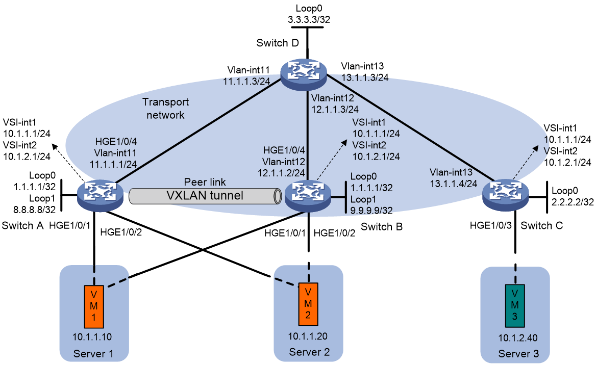
Procedure
|
|
IMPORTANT: By default, interfaces on the device are disabled (in ADM or Administratively Down state). To have an interface operate, you must use the undo shutdown command to enable that interface. By default, interfaces on the device operate in Layer 3 mode. In this example, you must use the port link-mode command to configure the interfaces that host Ethernet service instances to operate in Layer 2 mode. |
1. On VM 1 and VM 2, specify 10.1.1.1 as the gateway address. On VM 3, specify 10.1.2.1 as the gateway address. (Details not shown.)
2. Configure IP addresses and unicast routing settings:
# Assign IP addresses to interfaces (including loopback interfaces), as shown in Figure 12. (Details not shown.)
# Configure OSPF on all transport network switches (Switches A through D) for them to reach one another. (Details not shown.)
3. Configure Switch A:
# Enable L2VPN.
<SwitchA> system-view
[SwitchA] l2vpn enable
# Reserve VXLAN 1234.
[SwitchA] reserved vxlan 1234
# Configure M-LAG system settings.
[SwitchA] m-lag system-mac 0001-0001-0001
[SwitchA] m-lag system-number 1
[SwitchA] m-lag system-priority 10
[SwitchA] m-lag keepalive ip destination 11.1.1.1 source 12.1.1.2
[SwitchA] m-lag restore-delay 180
# Assign an IP address to Loopback 1. The IP address will be used as the source IP address of the peer link.
[SwitchA] interface loopback 1
[SwitchA-Loopback1] ip address 8.8.8.8 255.255.255.255
[SwitchA-Loopback1] quit
# Create a VXLAN tunnel to Switch B. The tunnel interface name is Tunnel 2. Configure the tunnel interface as a peer-link interface.
[SwitchA] interface tunnel 2 mode vxlan
[SwitchA-Tunnel2] source 8.8.8.8
[SwitchA-Tunnel2] destination 9.9.9.9
[SwitchA-Tunnel2] port m-lag peer-link 1
# Set the ToS of tunneled packets to 100.
[SwitchA-Tunnel2] tunnel tos 100
[SwitchA-Tunnel2] quit
# Create Layer 2 dynamic aggregate interface Bridge-Aggregation 4.
[SwitchA] interface bridge-aggregation 4
[SwitchA-Bridge-Aggregation4] link-aggregation mode dynamic
[SwitchA-Bridge-Aggregation4] quit
# Assign HundredGigE 1/0/1 to link aggregation group 4.
[SwitchA] interface hundredgige 1/0/1
[SwitchA-HundredGigE1/0/1] port link-aggregation group 4
[SwitchA-HundredGigE1/0/1] quit
# Create Layer 2 dynamic aggregate interface Bridge-Aggregation 5.
[SwitchA] interface bridge-aggregation 5
[SwitchA-Bridge-Aggregation5] link-aggregation mode dynamic
[SwitchA-Bridge-Aggregation5] quit
# Assign HundredGigE 1/0/2 to link aggregation group 5.
[SwitchA] interface hundredgige 1/0/2
[SwitchA-HundredGigE1/0/2] port link-aggregation group 5
[SwitchA-HundredGigE1/0/2] quit
# Create VSI vpna and VXLAN 10.
[SwitchA] vsi vpna
[SwitchA-vsi-vpna] vxlan 10
[SwitchA-vsi-vpna-vxlan-10] quit
[SwitchA-vsi-vpna] quit
# Create VSI vpnb and VXLAN 20.
[SwitchA] vsi vpnb
[SwitchA-vsi-vpnb] vxlan 20
[SwitchA-vsi-vpnb-vxlan-20] quit
[SwitchA-vsi-vpnb] quit
# Assign an IP address to Loopback 0. The IP address will be used as the source IP address of the VXLAN tunnel to Switch C.
[SwitchA] interface loopback 0
[SwitchA-Loopback0] ip address 1.1.1.1 255.255.255.255
[SwitchA-Loopback0] quit
# Create a VXLAN tunnel to Switch C. The tunnel interface name is Tunnel 1.
[SwitchA] interface tunnel 1 mode vxlan
[SwitchA-Tunnel1] source 1.1.1.1
[SwitchA-Tunnel1] destination 2.2.2.2
[SwitchA-Tunnel1] quit
# Assign Tunnel 1 to VXLAN 10.
[SwitchA] vsi vpna
[SwitchA-vsi-vpna] vxlan 10
[SwitchA-vsi-vpna-vxlan-10] tunnel 1
[SwitchA-vsi-vpna-vxlan-10] quit
[SwitchA-vsi-vpna] quit
# Assign Tunnel 1 to VXLAN 20.
[SwitchA] vsi vpnb
[SwitchA-vsi-vpnb] vxlan 20
[SwitchA-vsi-vpnb-vxlan-20] tunnel 1
[SwitchA-vsi-vpnb-vxlan-20] quit
[SwitchA-vsi-vpnb] quit
# On Bridge-Aggregation 4, create Ethernet service instance 1000 to match VLAN 1.
[SwitchA] interface bridge-aggregation 4
[SwitchA-Bridge-Aggregation4] port link-type trunk
[SwitchA-Bridge-Aggregation4] port trunk permit vlan 1
[SwitchA-Bridge-Aggregation4] service-instance 1000
[SwitchA-Bridge-Aggregation4-srv1000] encapsulation s-vid 1
# Map Ethernet service instance 1000 to VSI vpna.
[SwitchA-Bridge-Aggregation10-srv1000] xconnect vsi vpna
[SwitchA-Bridge-Aggregation10-srv1000] quit
# On Bridge-Aggregation 5, create Ethernet service instance 1000 to match VLAN 2.
[SwitchA] interface bridge-aggregation 5
[SwitchA-Bridge-Aggregation5] port link-type trunk
[SwitchA-Bridge-Aggregation5] port trunk permit vlan 2
[SwitchA-Bridge-Aggregation5] service-instance 1000
[SwitchA-Bridge-Aggregation5-srv1000] encapsulation s-vid 2
# Map Ethernet service instance 1000 to VSI vpna.
[SwitchA-Bridge-Aggregation5-srv1000] xconnect vsi vpna
[SwitchA-Bridge-Aggregation5-srv1000] quit
# Create VSI-interface 1 and assign the interface an IP address and a MAC address. The IP address will be used as the gateway address for VXLAN 10.
[SwitchA] interface vsi-interface 1
[SwitchA-Vsi-interface1] ip address 10.1.1.1 255.255.255.0
[SwitchA-Vsi-interface1] mac-address 1-1-1
# Specify VSI-interface 1 as a distributed gateway.
[SwitchA-Vsi-interface1] distributed-gateway local
[SwitchA-Vsi-interface1] quit
# Create VSI-interface 2 and assign the interface an IP address and a MAC address. The IP address will be used as the gateway address for VXLAN 20.
[SwitchA] interface vsi-interface 2
[SwitchA-Vsi-interface2] ip address 10.1.2.1 255.255.255.0
[SwitchA-Vsi-interface2] mac-address 2-2-2
# Specify VSI-interface 2 as a distributed gateway.
[SwitchA-Vsi-interface2] distributed-gateway local
[SwitchA-Vsi-interface2] quit
# Enable dynamic ARP entry synchronization for distributed VXLAN IP gateways.
[SwitchA] arp distributed-gateway dynamic-entry synchronize
# Specify VSI-interface 1 as the gateway interface for VSI vpna.
[SwitchA] vsi vpna
[SwitchA-vsi-vpna] gateway vsi-interface 1
[SwitchA-vsi-vpna] quit
# Specify VSI-interface 2 as the gateway interface for VSI vpnb.
[SwitchA] vsi vpnb
[SwitchA-vsi-vpnb] gateway vsi-interface 2
[SwitchA-vsi-vpnb] quit
# Exclude the interfaces used by VXLAN from the shutdown action by M-LAG MAD.
[SwitchA] m-lag mad exclude interface loopback 0
[SwitchA] m-lag mad exclude interface tunnel 2
[SwitchA] m-lag mad exclude interface vsi-interface 1
[SwitchA] m-lag mad exclude interface vsi-interface 2
[SwitchA] m-lag mad exclude interface vlan-interface 11
4. Configure Switch B:
# Enable L2VPN.
<SwitchB> system-view
[SwitchB] l2vpn enable
# Reserve VXLAN 1234.
[SwitchA] reserved vxlan 1234
# Configure M-LAG system settings.
[SwitchB] m-lag system-mac 0001-0001-0001
[SwitchB] m-lag system-number 2
[SwitchB] m-lag system-priority 10
[SwitchB] m-lag keepalive ip destination 12.1.1.2 source 11.1.1.1
[SwitchB] m-lag restore-delay 180
# Assign an IP address to Loopback 1. The IP address will be used as the source IP address of the peer link.
[SwitchB] interface loopback 1
[SwitchB-Loopback1] ip address 9.9.9.9 255.255.255.255
[SwitchB-Loopback1] quit
# Create a VXLAN tunnel to Switch B. The tunnel interface name is Tunnel 2. Configure the tunnel interface as a peer-link interface.
[SwitchB] interface tunnel 2 mode vxlan
[SwitchB-Tunnel2] source 9.9.9.9
[SwitchB-Tunnel2] destination 8.8.8.8
[SwitchB-Tunnel2] port m-lag peer-link 1
# Set the ToS of tunneled packets to 100.
[SwitchB-Tunnel2] tunnel tos 100
[SwitchB-Tunnel2] quit
# Create Layer 2 dynamic aggregate interface Bridge-Aggregation 4.
[SwitchB] interface bridge-aggregation 4
[SwitchB-Bridge-Aggregation4] link-aggregation mode dynamic
[SwitchB-Bridge-Aggregation4] quit
# Assign HundredGigE 1/0/1 to link aggregation group 4.
[SwitchB] interface hundredgige 1/0/1
[SwitchB-HundredGigE1/0/1] port link-aggregation group 4
[SwitchB-HundredGigE1/0/1] quit
# Create Layer 2 dynamic aggregate interface Bridge-Aggregation 5.
[SwitchB] interface bridge-aggregation 5
[SwitchB-Bridge-Aggregation5] link-aggregation mode dynamic
[SwitchB-Bridge-Aggregation5] quit
# Assign HundredGigE 1/0/2 to link aggregation group 5.
[SwitchB] interface hundredgige 1/0/2
[SwitchB-HundredGigE1/0/2] port link-aggregation group 5
[SwitchB-HundredGigE1/0/2] quit
# Create VSI vpna and VXLAN 10.
[SwitchB] vsi vpna
[SwitchB-vsi-vpna] vxlan 10
[SwitchB-vsi-vpna-vxlan-10] quit
[SwitchB-vsi-vpna] quit
# Create VSI vpnb and VXLAN 20.
[SwitchB] vsi vpnb
[SwitchB-vsi-vpnb] vxlan 20
[SwitchB-vsi-vpnb-vxlan-20] quit
[SwitchB-vsi-vpnb] quit
# Assign an IP address to Loopback 0. The IP address will be used as the source IP address of the VXLAN tunnel to Switch C.
[SwitchB] interface loopback 0
[SwitchB-Loopback0] ip address 1.1.1.1 255.255.255.255
[SwitchB-Loopback0] quit
# Create a VXLAN tunnel to Switch C. The tunnel interface name is Tunnel 1.
[SwitchB] interface tunnel 1 mode vxlan
[SwitchB-Tunnel1] source 1.1.1.1
[SwitchB-Tunnel1] destination 2.2.2.2
[SwitchB-Tunnel1] quit
# Assign Tunnel 1 to VXLAN 10.
[SwitchB] vsi vpna
[SwitchB-vsi-vpna] vxlan 10
[SwitchB-vsi-vpna-vxlan-10] tunnel 1
[SwitchB-vsi-vpna-vxlan-10] quit
[SwitchB-vsi-vpna] quit
# Assign Tunnel 1 to VXLAN 20.
[SwitchB] vsi vpnb
[SwitchB-vsi-vpnb] vxlan 20
[SwitchB-vsi-vpnb-vxlan-20] tunnel 1
[SwitchB-vsi-vpnb-vxlan-20] quit
[SwitchB-vsi-vpnb] quit
# On Bridge-Aggregation 4, create Ethernet service instance 1000 to match VLAN 1.
[SwitchB] interface bridge-aggregation 4
[SwitchB-Bridge-Aggregation4] port link-type trunk
[SwitchB-Bridge-Aggregation4] port trunk permit vlan 1
[SwitchB-Bridge-Aggregation4] service-instance 1000
[SwitchB-Bridge-Aggregation4-srv1000] encapsulation s-vid 1
# Map Ethernet service instance 1000 to VSI vpna.
[SwitchB-Bridge-Aggregation10-srv1000] xconnect vsi vpna
[SwitchB-Bridge-Aggregation10-srv1000] quit
# On Bridge-Aggregation 5, create Ethernet service instance 1000 to match VLAN 2.
[SwitchB] interface bridge-aggregation 5
[SwitchB-Bridge-Aggregation5] port link-type trunk
[SwitchB-Bridge-Aggregation5] port trunk permit vlan 2
[SwitchB-Bridge-Aggregation5] service-instance 1000
[SwitchB-Bridge-Aggregation5-srv1000] encapsulation s-vid 2
# Map Ethernet service instance 1000 to VSI vpna.
[SwitchB-Bridge-Aggregation5-srv1000] xconnect vsi vpna
[SwitchB-Bridge-Aggregation5-srv1000] quit
# Create VSI-interface 1 and assign the interface an IP address and a MAC address. The IP address will be used as the gateway address for VXLAN 10.
[SwitchB] interface vsi-interface 1
[SwitchB-Vsi-interface1] ip address 10.1.1.1 255.255.255.0
[SwitchB-Vsi-interface1] mac-address 1-1-1
# Specify VSI-interface 1 as a distributed gateway.
[SwitchB-Vsi-interface1] distributed-gateway local
[SwitchB-Vsi-interface1] quit
# Create VSI-interface 2 and assign the interface an IP address and a MAC address. The IP address will be used as the gateway address for VXLAN 20.
[SwitchB] interface vsi-interface 2
[SwitchB-Vsi-interface2] ip address 10.1.2.1 255.255.255.0
[SwitchB-Vsi-interface2] mac-address 2-2-2
# Specify VSI-interface 2 as a distributed gateway.
[SwitchB-Vsi-interface2] distributed-gateway local
[SwitchB-Vsi-interface2] quit
# Enable dynamic ARP entry synchronization for distributed VXLAN IP gateways.
[SwitchB] arp distributed-gateway dynamic-entry synchronize
# Specify VSI-interface 1 as the gateway interface for VSI vpna.
[SwitchB] vsi vpna
[SwitchB-vsi-vpna] gateway vsi-interface 1
[SwitchB-vsi-vpna] quit
# Specify VSI-interface 2 as the gateway interface for VSI vpnb.
[SwitchB] vsi vpnb
[SwitchB-vsi-vpnb] gateway vsi-interface 2
[SwitchB-vsi-vpnb] quit
# Exclude the interfaces used by VXLAN from the shutdown action by M-LAG MAD.
[SwitchB] m-lag mad exclude interface loopback 0
[SwitchB] m-lag mad exclude interface tunnel 2
[SwitchB] m-lag mad exclude interface vsi-interface 1
[SwitchB] m-lag mad exclude interface vsi-interface 2
[SwitchB] m-lag mad exclude interface vlan-interface 12
5. Configure Switch C:
# Enable L2VPN.
<SwitchC> system-view
[SwitchC] l2vpn enable
# Create VSI vpna and VXLAN 10.
[SwitchC] vsi vpna
[SwitchC-vsi-vpna] vxlan 10
[SwitchC-vsi-vpna-vxlan-10] quit
[SwitchC-vsi-vpna] quit
# Create VSI vpnb and VXLAN 20.
[SwitchC] vsi vpnb
[SwitchC-vsi-vpnb] vxlan 20
[SwitchC-vsi-vpnb-vxlan-20] quit
[SwitchC-vsi-vpnb] quit
# Assign an IP address to Loopback 0. The IP address will be used as the source IP address of the VXLAN tunnels to Switch A and Switch B.
[SwitchC] interface loopback 0
[SwitchC-Loopback0] ip address 2.2.2.2 255.255.255.255
[SwitchC-Loopback0] quit
# Create a VXLAN tunnel to Switch A and Switch B. The tunnel interface name is Tunnel 1.
[SwitchC] interface tunnel 1 mode vxlan
[SwitchC-Tunnel1] source 2.2.2.2
[SwitchC-Tunnel1] destination 1.1.1.1
[SwitchC-Tunnel1] quit
# Assign Tunnel 1 to VXLAN 10.
[SwitchC] vsi vpna
[SwitchC-vsi-vpna] vxlan 10
[SwitchC-vsi-vpna-vxlan-10] tunnel 1
[SwitchC-vsi-vpna-vxlan-10] quit
[SwitchC-vsi-vpna] quit
# Assign Tunnel 1 to VXLAN 20.
[SwitchC] vsi vpnb
[SwitchC-vsi-vpnb] vxlan 20
[SwitchC-vsi-vpnb-vxlan-20] tunnel 1
[SwitchC-vsi-vpnb-vxlan-20] quit
[SwitchC-vsi-vpnb] quit
# On HundredGigE 1/0/3, create Ethernet service instance 1000 to match VLAN 4.
[SwitchC] interface hundredgige 1/0/3
[SwitchC-HundredGigE1/0/3] port link-type trunk
[SwitchC-HundredGigE1/0/3] port trunk permit vlan 4
[SwitchC-HundredGigE1/0/3] service-instance 1000
[SwitchC-HundredGigE1/0/3] encapsulation s-vid 4
# Map Ethernet service instance 1000 to VSI vpnb.
[SwitchC-HundredGigE1/0/3] xconnect vsi vpnb
[SwitchC-HundredGigE1/0/3] quit
# Create VSI-interface 1 and assign the interface an IP address and a MAC address. The IP address will be used as the gateway address for VXLAN 10.
[SwitchC] interface vsi-interface 1
[SwitchC-Vsi-interface1] ip address 10.1.1.1 255.255.255.0
[SwitchC-Vsi-interface1] mac-address 1-1-1
# Specify VSI-interface 1 as a distributed gateway and enable local proxy ARP on the interface.
[SwitchC-Vsi-interface1] distributed-gateway local
[SwitchC-Vsi-interface1] local-proxy-arp enable
[SwitchC-Vsi-interface1] quit
# Create VSI-interface 2 and assign the interface an IP address and a MAC address. The IP address will be used as the gateway address for VXLAN 20.
[SwitchC] interface vsi-interface 2
[SwitchC-Vsi-interface2] ip address 10.1.2.1 255.255.255.0
[SwitchC-Vsi-interface2] mac-address 2-2-2
# Specify VSI-interface 2 as a distributed gateway and enable local proxy ARP on the interface.
[SwitchC-Vsi-interface2] distributed-gateway local
[SwitchC-Vsi-interface2] local-proxy-arp enable
[SwitchC-Vsi-interface2] quit
# Enable dynamic ARP entry synchronization for distributed VXLAN IP gateways.
[SwitchC] arp distributed-gateway dynamic-entry synchronize
# Specify VSI-interface 1 as the gateway interface for VSI vpna.
[SwitchC] vsi vpna
[SwitchC-vsi-vpna] gateway vsi-interface 1
[SwitchC-vsi-vpna] quit
# Specify VSI-interface 2 as the gateway interface for VSI vpnb.
[SwitchC] vsi vpnb
[SwitchC-vsi-vpnb] gateway vsi-interface 2
[SwitchC-vsi-vpnb] quit
Verifying the configuration
1. Verify the M-LAG configuration on Switch A:
# Verify that the VXLAN tunnel to Switch C is up, and the tunnel source address is 1.1.1.1.
[SwitchA] display interface tunnel
Tunnel1
Current state: UP
Line protocol state: UP
Description: Tunnel1 Interface
Bandwidth: 64 kbps
Maximum transmission unit: 64000
Internet protocol processing: Disabled
Last clearing of counters: Never
Tunnel source 1.1.1.1, destination 2.2.2.2
Tunnel protocol/transport UDP_VXLAN/IP
Last 300 seconds input rate: 0 bytes/sec, 0 bits/sec, 0 packets/sec
Last 300 seconds output rate: 73 bytes/sec, 584 bits/sec, 0 packets/sec
Input: 0 packets, 0 bytes, 0 drops
Output: 161 packets, 22684 bytes, 0 drops
Tunnel2
Current state: UP
Line protocol state: UP
Description: Tunnel2 Interface
Bandwidth: 64 kbps
Maximum transmission unit: 64000
Internet protocol processing: Disabled
Last clearing of counters: Never
Tunnel source 8.8.8.8, destination 9.9.9.9
Tunnel protocol/transport UDP_VXLAN/IP
Last 300 seconds input rate: 153 bytes/sec, 1224 bits/sec, 0 packets/sec
Last 300 seconds output rate: 775 bytes/sec, 6200 bits/sec, 3 packets/sec
Input: 298 packets, 47222 bytes, 0 drops
Output: 978 packets, 233157 bytes, 0 drops
# Verify that the VXLAN tunnels have been assigned to the VSIs, the VSI interfaces are the gateway interfaces of their respective VXLANs, and the ACs are up. This step uses VSI vpna as an example.
[SwitchA] display l2vpn vsi name vpna verbose
VSI Name: vpna
VSI Index : 0
VSI State : Up
MTU : 1500
Diffserv Mode : -
Bandwidth : Unlimited
Broadcast Restrain : Unlimited
Multicast Restrain : Unlimited
Unknown Unicast Restrain: Unlimited
MAC Learning : Enabled
MAC Table Limit : -
MAC Learning rate : -
Drop Unknown : -
PW Redundancy Mode : Slave
Flooding : Enabled
ESI : 0000.0000.0000.0000.0000
Redundancy Mode : All-active
Statistics : Disabled
Gateway Interface : VSI-interface 1
VXLAN ID : 10
Tunnels:
Tunnel Name Link ID State Type Flood proxy
Tunnel1 0x5000001 UP Manual Disabled
Tunnel2 0x5000002 UP Manual Disabled
ACs:
AC Link ID State Type
BAGG4 srv1000 0x0 Up Manual
BAGG5 srv1000 0x1 Up Manual
Statistics: Disabled
2. Verify the distributed VXLAN IP gateway settings on Switch C:
# Verify that the VXLAN tunnel to Switch A and Switch B is up.
[SwitchC] display interface tunnel
Tunnel1
Current state: UP
Line protocol state: UP
Description: Tunnel1 Interface
Bandwidth: 64 kbps
Maximum transmission unit: 64000
Internet protocol processing: Disabled
Last clearing of counters: Never
Tunnel source 2.2.2.2, destination 1.1.1.1
Tunnel protocol/transport UDP_VXLAN/IP
Last 300 seconds input rate: 0 bytes/sec, 0 bits/sec, 0 packets/sec
Last 300 seconds output rate: 0 bytes/sec, 0 bits/sec, 0 packets/sec
Input: 8 packets, 480 bytes, 0 drops
Output: 4 packets, 240 bytes, 0 drops
# Verify that the VXLAN tunnel has been assigned to the VXLANs, and that the VSI interfaces are the gateway interfaces of their respective VXLANs.
[SwitchC] dis l2vpn vsi verbose
VSI Name: vpna
VSI Index : 0
VSI State : Up
MTU : 1500
Diffserv Mode : -
Bandwidth : Unlimited
Broadcast Restrain : Unlimited
Multicast Restrain : Unlimited
Unknown Unicast Restrain: Unlimited
MAC Learning : Enabled
MAC Table Limit : -
MAC Learning rate : -
Drop Unknown : -
PW Redundancy Mode : Slave
Flooding : Enabled
ESI : 0000.0000.0000.0000.0000
Redundancy Mode : All-active
Statistics : Disabled
Gateway Interface : VSI-interface 1
VXLAN ID : 10
Tunnels:
Tunnel Name Link ID State Type Flood proxy
Tunnel1 0x5000001 UP Manual Disabled
VSI Name: vpnb
VSI Index : 1
VSI State : Up
MTU : 1500
Diffserv Mode : -
Bandwidth : Unlimited
Broadcast Restrain : Unlimited
Multicast Restrain : Unlimited
Unknown Unicast Restrain: Unlimited
MAC Learning : Enabled
MAC Table Limit : -
MAC Learning rate : -
Drop Unknown : -
PW Redundancy Mode : Slave
Flooding : Enabled
ESI : 0000.0000.0000.0000.0000
Redundancy Mode : All-active
Statistics : Disabled
Gateway Interface : VSI-interface 2
VXLAN ID : 20
Tunnels:
Tunnel Name Link ID State Type Flood proxy
Tunnel1 0x5000001 UP Manual Disabled
3. Verify network connectivity for the VMs:
# Verify that VM 1, VM 2, and VM 3 can communicate when both Switch A and Switch B are operating correctly. (Details not shown.)
# Verify that VM 1, VM 2, and VM 3 can communicate when Switch A's or Switch B's links to the local site are disconnected. (Details not shown.)
