- Table of Contents
- Related Documents
-
| Title | Size | Download |
|---|---|---|
| 01-Hardware Information and Specifications | 1.52 MB |
1 Product models and technical specifications
3 Removable components and compatibility matrixes
Connecting cables to the ports on expansion cards
10/100/1000BASE-T Ethernet port
10/100/1000BASE-T autosensing Ethernet port LED
Port status LED on the expansion card
1 Product models and technical specifications
Unless otherwise stated, power supplies and power modules are used interchangeably in this document.
Product models
Table1-1 Switch series and models
|
Model |
Product code (PID) |
||
|
S5590-HI switch series |
Non-PoE models |
S5590-28T8XC-HI |
LS-5590-28T8XC-HI |
|
S5590-48T4XC-HI |
LS-5590-48T4XC-HI |
||
|
S5590-28S8XC-HI |
LS-5590-28S8XC-HI |
||
|
S5590-48S4XC-HI |
LS-5590-48S4XC-HI |
||
|
S5590-EI switch series |
Non-PoE models |
S5590-28T8XC-EI |
LS-5590-28T8XC-EI |
|
S5590-48T4XC-EI |
LS-5590-48T4XC-EI |
||
|
S5590-28S8XC-EI |
LS-5590-28S8XC-EI |
||
|
LS-5590-28S8XC-EI-GL |
|||
|
S5590-48S4XC-EI |
LS-5590-48S4XC-EI |
||
|
LS-5590-48S4XC-EI-GL |
|||
|
PoE models |
S5590-28P8XC-EI |
LS-5590-28P8XC-EI |
|
|
LS-5590-28P8XC-EI-GL |
|||
|
S5590-48P6XC-EI |
LS-5590-48P6XC-EI |
||
|
LS-5590-48P6XC-EI-GL |
|||
Technical specifications
S5590-HI switch series
Table1-2 Technical specifications
|
Item |
S5590-28T8XC-HI |
S5590-48T4XC-HI |
S5590-28S8XC-HI |
S5590-48S4XC-HI |
|
Dimensions (H × W × D) |
44 × 440 × 400 mm (1.73 × 17.32 × 15.75 in) |
44 × 440 × 400 mm (1.73 × 17.32 × 15.75 in) |
44 × 440 × 400 mm (1.73 × 17.32 × 15.75 in) |
44 × 440 × 400 mm (1.73 × 17.32 × 15.75 in) |
|
Weight |
≤ 8 kg (17.64 lb) |
≤ 8 kg (17.64 lb) |
≤ 8 kg (17.64 lb) |
≤ 8 kg (17.64 lb) |
|
Console port |
1 × serial console port |
|||
|
USB port |
1 |
|||
|
Management Ethernet port |
1 |
|||
|
SFP+ port |
8 |
4 |
8 |
4 |
|
SFP port |
4 (Each and its corresponding 10/100/1000BASE-T autosensing Ethernet port form a combo interface.) |
N/A |
28 (The four highest-numbered SFP ports and their corresponding 10/100/1000BASE-T autosensing Ethernet ports form combo interfaces.) |
48 (The four highest-numbered SFP ports cannot be used when the port rate mode of the expansion slots is mode2.) |
|
10/100/1000BASE-T autosensing Ethernet port |
28 (The four highest-numbered 10/100/1000BASE-T autosensing Ethernet ports and their corresponding SFP ports form combo interfaces.) |
48 (The four highest-numbered 10/100/1000BASE-T autosensing Ethernet ports cannot be used when the port rate mode of the expansion slots is mode 2.) |
4 (Each and its corresponding SFP port form a combo interface.) |
N/A |
|
Expansion slot |
2 |
|||
|
Power supply slot |
2 |
|||
|
Fan tray slot |
2 |
|||
|
Input voltage |
AC input: · Rated voltage range: 100 VAC to 240 VAC @ 50 Hz or 60 Hz · Max voltage range: 90 VAC to 264 VAC @ 47 Hz to 63 Hz HVDC input: · Rated voltage range: 240 VDC · Max voltage range: 180 VDC to 320 VDC |
|||
|
Minimum power consumption |
Single power input: 42 W Dual power inputs: 47 W |
Single power input: 44 W Dual power inputs: 50 W |
Single power input: 43 W Dual power inputs: 49 W |
Single power input: 47 W Dual power inputs: 55 W |
|
Maximum power consumption |
Single power input: 136 W Dual power inputs: 141 W |
Single power input: 132 W Dual power inputs: 136 W |
Single power input: 138 W Dual power inputs: 142 W |
Single power input: 152 W Dual power inputs: 156 W |
|
Chassis leakage current compliance |
UL62368-1/EN62368-1/IEC62368-1/UL60950-1/EN60950-1/IEC60950-1/GB4943.1 |
|||
|
Melting current of power supply fuse |
6.3 A/250 V |
|||
|
Operating temperature |
–5°C to +45°C (23°F to 113°F) |
|||
|
Operating humidity |
5% RH to 95% RH, noncondensing |
|||
|
Fire resistance compliance |
UL62368-1/EN62368-1/IEC62368-1/UL60950-1/EN60950-1/IEC60950-1/GB4943.1 |
|||
S5590-EI switch series
Table1-3 Technical specifications for non-PoE switch models
|
Item |
S5590-28T8XC-EI |
S5590-48T4XC-EI |
S5590-28S8XC-EI |
S5590-48S4XC-EI |
|
Dimensions (H × W × D) |
44 × 440 × 360 mm (1.73 × 17.32 × 14.17 in) |
44 × 440 × 360 mm (1.73 × 17.32 × 14.17 in) |
44 × 440 × 360 mm (1.73 × 17.32 × 14.17 in) |
44 × 440 × 360 mm (1.73 × 17.32 × 14.17 in) |
|
Weight |
≤ 7 kg (15.43 lb) |
≤ 7 kg (15.43 lb) |
≤ 7 kg (15.43 lb) |
≤ 7 kg (15.43 lb) |
|
Console port |
1 × serial console port |
|||
|
USB port |
1 |
|||
|
Management Ethernet port |
1 |
|||
|
SFP+ port |
8 |
4 |
8 |
4 |
|
SFP port |
4 (Each and its corresponding 10/100/1000BASE-T autosensing Ethernet port form a combo interface.) |
N/A |
28 (The four highest-numbered SFP ports and their corresponding 10/100/1000BASE-T autosensing Ethernet ports form combo interfaces.) |
48 |
|
10/100/1000BASE-T autosensing Ethernet port |
28 (The four highest-numbered 10/100/1000BASE-T autosensing Ethernet ports and their corresponding SFP ports form combo interfaces.) |
48 |
4 (Each and its corresponding SFP port form a combo interface.) |
N/A |
|
Expansion slot |
1 |
|||
|
Power supply slot |
2 |
|||
|
Fan tray slot |
2 |
|||
|
Input voltage |
PSR180-12A-F/PSR180-12A-B power supply: · Rated voltage range: 100 VAC to 240 VAC @ 50 Hz or 60 Hz · Max voltage range: 90 VAC to 290 VAC @ 47 Hz to 63 Hz PSR180-12D-B power supply: · Rated voltage range: –48 VDC to +60 VDC · Max voltage range: –36 VDC to +72 VDC DC power source for the PSR180-12D-B power supply: –48 VDC power source in the equipment room or an RPS (H3C RPS800-A or RPS1600-A) |
|||
|
Minimum power consumption |
Single power input: 38 W Dual power inputs: 45 W |
Single power input: 41 W Dual power inputs: 48 W |
Single power input: 39 W Dual power inputs: 46 W |
Single power input: 42 W Dual power inputs: 49 W |
|
Maximum power consumption |
Single power input: 108 W Dual power inputs: 114 W |
Single power input: 105 W Dual power inputs: 108 W |
Single power input: 119 W Dual power inputs: 123 W |
Single power input: 137 W Dual power inputs: 142 W |
|
Chassis leakage current compliance |
UL62368-1/EN62368-1/IEC62368-1/UL60950-1/EN60950-1/IEC60950-1/GB4943.1 |
|||
|
Melting current of power supply fuse |
6.3 A/250 V |
|||
|
Operating temperature |
–5°C to +45°C (23°F to 113°F) |
|||
|
Operating humidity |
5% RH to 95% RH, noncondensing |
|||
|
Fire resistance compliance |
UL62368-1/EN62368-1/IEC62368-1/UL60950-1/EN60950-1/IEC60950-1/GB4943.1 |
|||
Table1-4 Technical specifications for PoE switch models
|
Item |
S5590-28P8XC-EI |
S5590-48P6XC-EI |
|
Dimensions (H × W × D) |
44 × 440 × 400 mm (1.73 × 17.32 × 15.75 in) |
44 × 440 × 400 mm (1.73 × 17.32 × 15.75 in) |
|
Weight |
≤ 7 kg (15.43 lb) |
≤ 7 kg (15.43 lb) |
|
Console port |
1 × serial console port |
|
|
USB port |
1 |
|
|
Management Ethernet port |
1 |
|
|
SFP+ port |
8 |
6 |
|
SFP port |
4 (Each and its corresponding 10/100/1000BASE-T autosensing Ethernet port form a combo interface.) |
N/A |
|
10/100/1000BASE-T autosensing Ethernet port |
28 (The four highest-numbered 10/100/1000BASE-T autosensing Ethernet ports and their corresponding SFP ports form combo interfaces.) |
48 |
|
Expansion slot |
1 |
|
|
Power supply slot |
2 |
|
|
Fan tray slot |
2 |
|
|
Input voltage |
· AC power input: ¡ Rated voltage range: 100 VAC to 240 VAC @ 50 Hz or 60 Hz ¡ Max voltage range: 90 VAC to 290 VAC @ 47 Hz to 63 Hz · HVDC power input: ¡ Rated voltage range: 240 VDC ¡ Max voltage range: 180 VDC to 320 VDC |
|
|
Minimum power consumption |
Single power input: 48 W Dual power inputs: 53 W |
Single power input: 52 W Dual power inputs: 59 W |
|
Maximum power consumption |
Single power input: 938 W Dual power inputs: 1046 W |
Single power input: 945 W Dual power inputs: 1745 W |
|
Chassis leakage current compliance |
UL62368-1/EN62368-1/IEC62368-1/UL60950-1/EN60950-1/IEC60950-1/GB4943.1 |
|
|
Melting current of power supply fuse |
· PSR600-54A-B power supply: 10 A/500 V · PSR920-54A-B power supply: 16 A/250 V · PSR1600-54A-B power supply: 16 A/250 V |
|
|
Operating temperature |
–5°C to +45°C (23°F to 113°F) |
|
|
Operating humidity |
5% RH to 95% RH, noncondensing |
|
|
Fire resistance compliance |
UL62368-1/EN62368-1/IEC62368-1/UL60950-1/EN60950-1/IEC60950-1/GB4943.1 |
|
Table1-5 PoE power capacity of the S5590-28P8XC-EI and S5590-48P6XC-EI switches
|
Power supply configuration |
S5590-28P8XC-EI |
S5590-48P6XC-EI |
||
|
Total PoE power capacity |
Max PoE power capacity per port |
Total PoE power capacity |
Max PoE power capacity per port |
|
|
1 × PSR600-54A-B |
450 W |
30 W |
450 W |
30 W |
|
1 × PSR920-54A-B |
770 W |
30 W |
770 W |
30 W |
|
1 × PSR1600-54A-B (input voltage: 90 VAC to 176 VAC) |
770 W |
30 W |
770 W |
30 W |
|
1 × PSR1600-54A-B (input voltage: 176 VAC to 1290 VAC or 180 VDC to 320 VDC) |
1000 W |
30 W |
1450 W |
30 W |
|
2 × PSR600-54A-B |
1000 W |
30 W |
1020 W |
30 W |
|
1 × PSR600-54A-B and 1 × PSR920-54A-B |
1000 W |
30 W |
1020 W |
30 W |
|
1 × PSR600-54A-B and 1 × PSR1600-54A-B (input voltage: 90 VAC to 176 VAC) |
1000 W |
30 W |
1020 W |
30 W |
|
1 × PSR920-54A-B and 1 × PSR1600-54A-B (input voltage: 176 VAC to 1290 VAC) |
1000 W |
30 W |
1260 W |
30 W |
|
1 × PSR600-54A-B and 1 × PSR1600-54A-B (input voltage: 176 VAC to 1290 VAC or 180 VDC to 320 VDC) |
1000 W |
30 W |
1020 W |
30 W |
|
1 × PSR920-54A-B and 1 × PSR1600-54A-B (input voltage: 176 VAC to 1290 VAC or 180 VDC to 320 VDC) |
1000 W |
30 W |
1600 W |
30 W |
|
1 × PSR1600-54A-B (input voltage: 176 VAC to 1290 VAC) and 1 × PSR1600-54A-B (input voltage: 176 VAC to 1290 VAC or 180 VDC to 320 VDC) |
1000 W |
30 W |
1600 W |
30 W |
|
2 × PSR920-54A-B |
1000 W |
30 W |
1600 W |
30 W |
|
2 × PSR1600-54A-B (input voltage: 90 VAC to 176 VAC) |
1000 W |
30 W |
1600 W |
30 W |
|
2 × PSR1600-54A-B (input voltage: 176 VAC to 1290 VAC or 180 VDC to 320 VDC) |
1000 W |
30 W |
1680 W |
30 W |
2 Chassis views
S5590-HI switch series
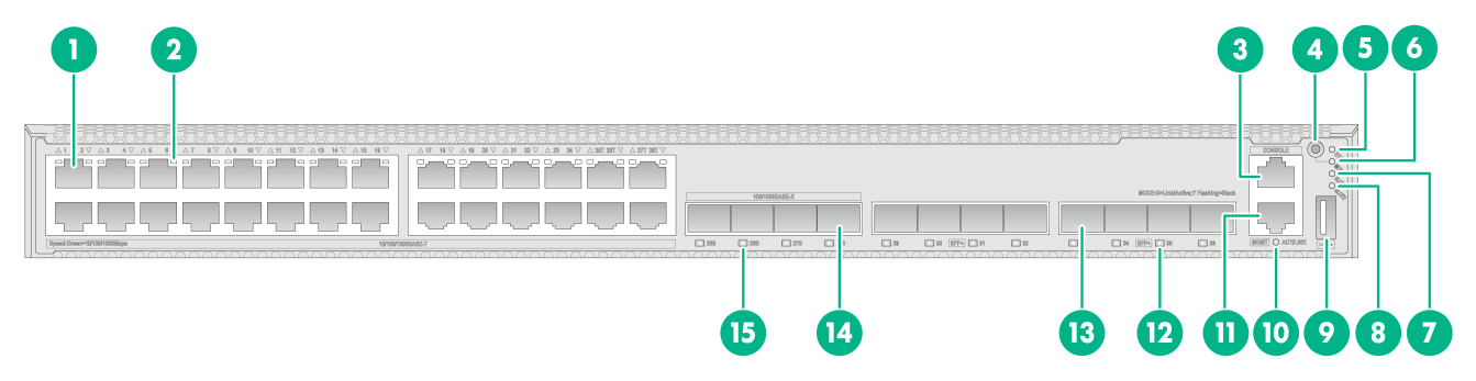
S5590-28T8XC-HI
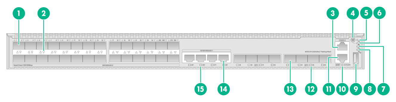
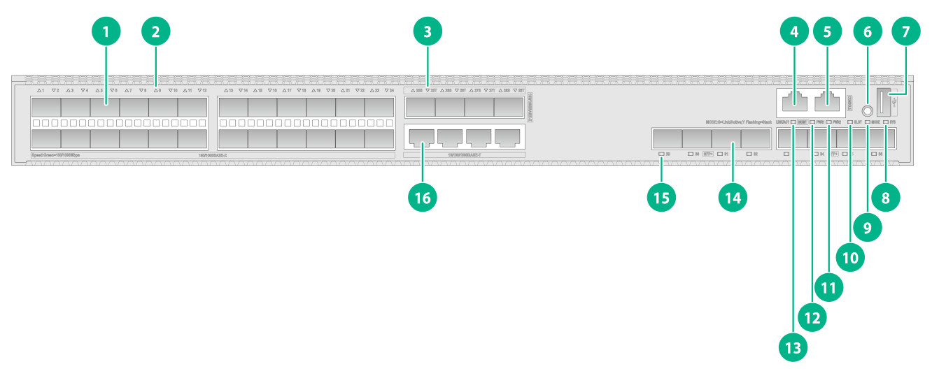
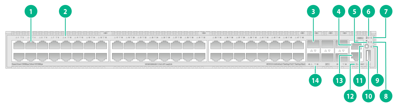
Figure2-1 Front panel
|
(1) 10/100/1000BASE-T autosensing Ethernet port |
(2) 10/100/1000BASE-T autosensing Ethernet port LED |
|
(3) Console port (CONSOLE) |
(4) Mode button |
|
(5) System status LED (SYS) |
(6) Mode LED (MODE) |
|
(7) Expansion card status LED 1 (SLOT1) |
(8) Expansion card status LED 2 (SLOT2) |
|
(9) USB port |
(10) Management Ethernet port LED (ACT/LINK) |
|
(11) Management Ethernet port (MGMT) |
(12) SFP+ port LED |
|
(13) SFP+ port |
(14) SFP port |
|
(15) SFP port LED |
|

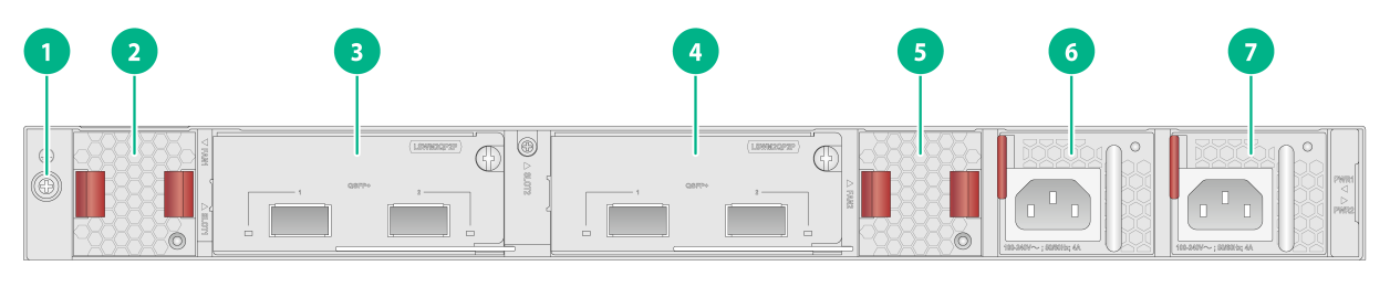
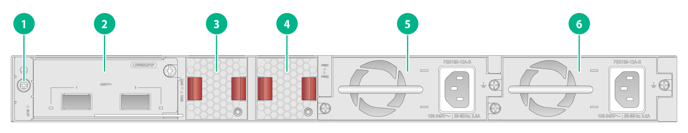
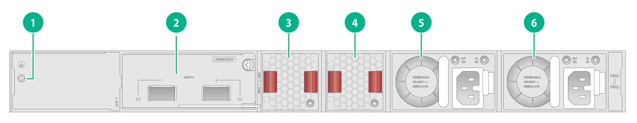
|
(1) Grounding screw |
(2) Fan tray 1 |
|
(3) Expansion card 1 |
(4) Expansion card 2 |
|
(5) Fan tray 2 |
(6) Power supply 1 |
|
(7) Power supply 2 |
|
The S5590-28T8XC-HI switch came with power supply slot 1 empty and power supply slot 2 installed with a filler panel. You can install one or two power supplies for the switch as required. In Figure2-2, two PSR250-12A1 AC power supplies are installed in the power supply slots.
The S5590-28T8XC-HI switch came with two fan tray slots empty. You must install two fan trays of the same model for the switch. In Figure2-2, two LSPM1FANSB-SN fan trays are installed in the fan tray slots.
The S5590-28T8XC-HI switch came with two expansion slots each installed with a filler panel. You can select expansion cards for the switch as required. In Figure2-2, two LSWM2QP2P interface cards are installed in the expansion slots.
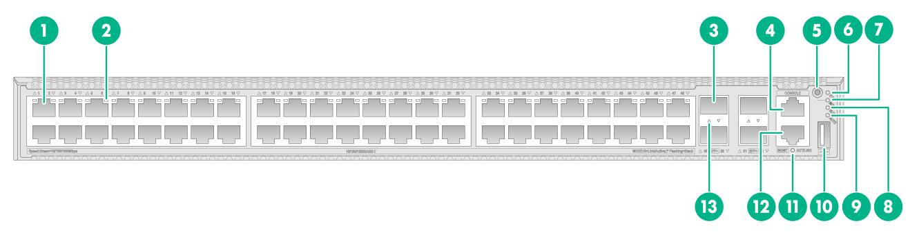
S5590-48T4XC-HI
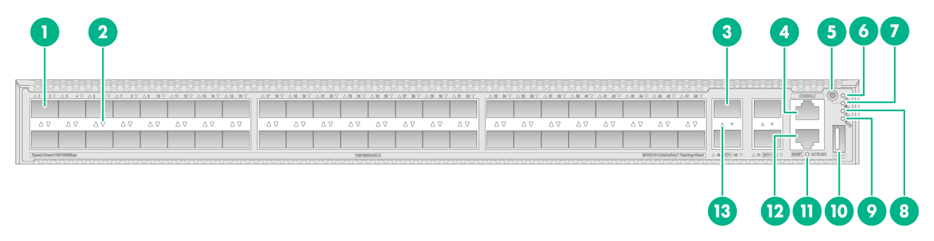
Figure2-3 Front panel
|
(1) 10/100/1000BASE-T autosensing Ethernet port |
(2) 10/100/1000BASE-T autosensing Ethernet port LED |
|
(3) SFP+ port |
(4) Console port (CONSOLE) |
|
(5) Mode button |
(6) System status LED (SYS) |
|
(7) Mode LED (MODE) |
(8) Expansion card status LED 1 (SLOT1) |
|
(9) Expansion card status LED 2 (SLOT2) |
(10) USB port |
|
(11) Management Ethernet port LED (ACT/LINK) |
(12) Management Ethernet port (MGMT) |
|
(13) SFP+ port LED |
|
|
(1) Grounding screw |
(2) Fan tray 1 |
|
(3) Expansion card 1 |
(4) Expansion card 2 |
|
(5) Fan tray 2 |
(6) Power supply 1 |
|
(7) Power supply 2 |
|
The S5590-48T4XC-HI switch came with power supply slot 1 empty and power supply slot 2 installed with a filler panel. You can install one or two power supplies for the switch as required. In Figure2-4, two PSR250-12A1 AC power supplies are installed in the power supply slots.
The S5590-48T4XC-HI switch came with two fan tray slots empty. You must install two fan trays of the same model for the switch. In Figure2-4, two LSPM1FANSB-SN fan trays are installed in the fan tray slots.
The S5590-48T4XC-HI switch came with two expansion slots each installed with a filler panel. You can select expansion cards for the switch as required. In Figure2-4, two LSWM2QP2P interface cards are installed in the expansion slots.
S5590-28S8XC-HI
Figure2-5 Front panel
|
(1) SFP port |
(2) SFP port LED |
|
(3) Console port (CONSOLE) |
(4) Mode button |
|
(5) System status LED (SYS) |
(6) Mode LED (MODE) |
|
(7) Expansion card status LED 1 (SLOT1) |
(8) Expansion card status LED 2 (SLOT2) |
|
(9) USB port |
(10) Management Ethernet port LED (ACT/LINK) |
|
(11) Management Ethernet port (MGMT) |
(12) SFP+ port LED |
|
(13) SFP+ port |
(14) 10/100/1000BASE-T autosensing Ethernet port |
|
(15) 10/100/1000BASE-T autosensing Ethernet port LED |
|

|
(1) Grounding screw |
(2) Fan tray 1 |
|
(3) Expansion card 1 |
(4) Expansion card 2 |
|
(5) Fan tray 2 |
(6) Power supply 1 |
|
(7) Power supply 2 |
|
The S5590-28S8XC-HI switch came with power supply slot 1 empty and power supply slot 2 installed with a filler panel. You can install one or two power supplies for the switch as required. In Figure2-6, two PSR250-12A1 AC power supplies are installed in the power supply slots.
The S5590-28S8XC-HI switch came with two fan tray slots empty. You must install two fan trays of the same model for the switch. In Figure2-6, two LSPM1FANSB-SN fan trays are installed in the fan tray slots.
The S5590-28S8XC-HI switch came with two expansion slots each installed with a filler panel. You can select expansion cards for the switch as required. In Figure2-6, two LSWM2QP2P interface cards are installed in the expansion slots.
S5590-48S4XC-HI
Figure2-7 Front panel
|
(1) SFP port |
(2) SFP port LED |
|
(3) SFP+ port |
(4) Console port (CONSOLE) |
|
(5) Mode button |
(6) System status LED (SYS) |
|
(7) Mode LED (MODE) |
(8) Expansion card status LED 1 (SLOT1) |
|
(9) Expansion card status LED 2 (SLOT2) |
(10) USB port |
|
(11) Management Ethernet port LED (ACT/LINK) |
(12) Management Ethernet port (MGMT) |
|
(13) SFP+ port LED |
|

|
(1) Grounding screw |
(2) Fan tray 1 |
|
(3) Expansion card 1 |
(4) Expansion card 2 |
|
(5) Fan tray 2 |
(6) Power supply 1 |
|
(7) Power supply 2 |
|
The S5590-48S4XC-HI switch came with power supply slot 1 empty and power supply slot 2 installed with a filler panel. You can install one or two power supplies for the switch as required. In Figure2-8, two PSR250-12A1 AC power supplies are installed in the power supply slots.
The S5590-48S4XC-HI switch came with two fan tray slots empty. You must install two fan trays of the same model for the switch. In Figure2-8, two LSPM1FANSB-SN fan trays are installed in the fan tray slots.
The S5590-48S4XC-HI switch came with two expansion slots each installed with a filler panel. You can select expansion cards for the switch as required. In Figure2-8, two LSWM2QP2P interface cards are installed in the expansion slots.
S5590-EI switch series
S5590-28T8XC-EI
Figure2-9 Front panel
|
(1) 10/100/1000BASE-T autosensing Ethernet port |
(2) 10/100/1000BASE-T autosensing Ethernet port LED |
|
(3) SFP port |
(4) SFP+ port |
|
(5) Management Ethernet port (MGMT) |
(6) Console port (CONSOLE) |
|
(7) Mode button |
(8) USB port |
|
(9) System status LED (SYS) |
(10) Mode LED (MODE) |
|
(11) Expansion card status LED (SLOT) |
(12) Power supply 2 status LED (PWR2) |
|
(13) Power supply 1 status LED (PWR1) |
(14) Management Ethernet port LED (ACT/LINK) |
|
(15) SFP+ port LED |
(16) SFP port LED |

|
(1) Grounding screw |
(2) Expansion card |
|
(3) Fan tray 1 |
(4) Fan tray 2 |
|
(5) Power supply 1 |
(6) Power supply 2 |
The S5590-28T8XC-EI switch came with power supply slot 1 empty and power supply slot 2 installed with a filler panel. You can install one or two power supplies for the switch as required. In Figure2-10, two PSR180-12A-B AC power supplies are installed in the power supply slots.
The S5590-28T8XC-EI switch came with two fan tray slots empty. You must install two fan trays of the same model for the switch. In Figure2-10, two LSPM1FANSB-SN fan trays are installed in the fan tray slots.
The S5590-28T8XC-EI switch came with one expansion slot installed with a filler panel. You can select an expansion card for the switch as required. In Figure2-10, an LSWM2QP2P interface card is installed in the expansion slot.
S5590-48T4XC-EI
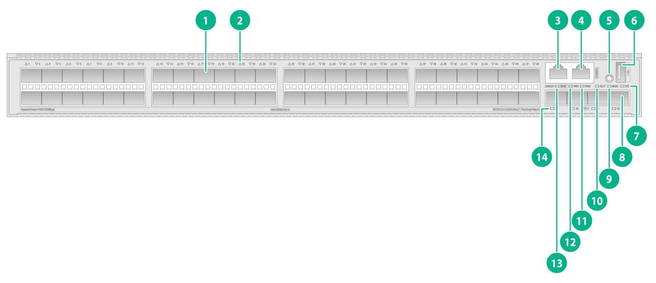
Figure2-11 Front panel
|
(1) 10/100/1000BASE-T autosensing Ethernet port |
(2) 10/100/1000BASE-T autosensing Ethernet port LED |
|
(3) Management Ethernet port (MGMT) |
(4) Console port (CONSOLE) |
|
(5) Mode button |
(6) USB port |
|
(7) System status LED (SYS) |
(8) SFP+ port |
|
(9) Mode LED (MODE) |
(10) Expansion card status LED (SLOT) |
|
(11) Power supply 2 status LED (PWR2) |
(12) Power supply 1 status LED (PWR1) |
|
(13) Management Ethernet port LED (ACT/LINK) |
(14) SFP+ port LED |

|
(1) Grounding screw |
(2) Expansion card |
|
(3) Fan tray 1 |
(4) Fan tray 2 |
|
(5) Power supply 1 |
(6) Power supply 2 |
The S5590-48T4XC-EI switch came with power supply slot 1 empty and power supply slot 2 installed with a filler panel. You can install one or two power supplies for the switch as required. In Figure2-12, two PSR180-12A-B AC power supplies are installed in the power supply slots.
The S5590-48T4XC-EI switch came with two fan tray slots empty. You must install two fan trays of the same model for the switch. In Figure2-12, two LSPM1FANSB-SN fan trays are installed in the fan tray slots.
The S5590-48T4XC-EI switch came with one expansion slot installed with a filler panel. You can select an expansion card for the switch as required. In Figure2-12, an LSWM2QP2P interface card is installed in the expansion slot.
S5590-28S8XC-EI
Figure2-13 Front panel
|
(1) SFP port |
(2) SFP port LED |
|
(3) 10/100/1000BASE-T autosensing Ethernet port LED |
(4) Management Ethernet port (MGMT) |
|
(5) Console port (CONSOLE) |
(6) Mode button |
|
(7) USB port |
(8) System status LED (SYS) |
|
(9) Mode LED (MODE) |
(10) Expansion card status LED (SLOT) |
|
(11) Power supply 2 status LED (PWR2) |
(12) Power supply 1 status LED (PWR1) |
|
(13) Management Ethernet port LED (ACT/LINK) |
(14) SFP+ port |
|
(15) SFP+ port LED |
(16) 10/100/1000BASE-T autosensing Ethernet port |

|
(1) Grounding screw |
(2) Expansion card |
|
(3) Fan tray 1 |
(4) Fan tray 2 |
|
(5) Power supply 1 |
(6) Power supply 2 |
The S5590-28S8XC-EI switch came with power supply slot 1 empty and power supply slot 2 installed with a filler panel. You can install one or two power supplies for the switch as required. In Figure2-14, two PSR180-12A-B AC power supplies are installed in the power supply slots.
The S5590-28S8XC-EI switch came with two fan tray slots empty. You must install two fan trays of the same model for the switch. In Figure2-14, two LSPM1FANSB-SN fan trays are installed in the fan tray slots.
The S5590-28S8XC-EI switch came with one expansion slot installed with a filler panel. You can select an expansion card for the switch as required. In Figure2-14, an LSWM2QP2P interface card is installed in the expansion slot.
The S5590-28S8XC-EI switch with PID LS-5590-28S8XC-EI-GL supports shipping with fan trays and power supplies installed. For the switch to be shipped with fan trays or power supplies installed, contact the marketing staff.
S5590-48S4XC-EI
Figure2-15 Front panel
|
(1) SFP port |
(2) SFP port LED |
|
(3) Management Ethernet port (MGMT) |
(4) Console port (CONSOLE) |
|
(5) Mode button |
(6) USB port |
|
(7) System status LED (SYS) |
(8) SFP+ port |
|
(9) Mode LED (MODE) |
(10) Expansion card status LED (SLOT) |
|
(11) Power supply 2 status LED (PWR2) |
(12) Power supply 1 status LED (PWR1) |
|
(13) Management Ethernet port LED (ACT/LINK) |
(14) SFP+ port LED |
|
(1) Grounding screw |
(2) Expansion card |
|
(3) Fan tray 1 |
(4) Fan tray 2 |
|
(5) Power supply 1 |
(6) Power supply 2 |
The S5590-48S4XC-EI switch came with power supply slot 1 empty and power supply slot 2 installed with a filler panel. You can install one or two power supplies for the switch as required. In Figure2-16, two PSR180-12A-B AC power supplies are installed in the power supply slots.
The S5590-48S4XC-EI switch came with two fan tray slots empty. You must install two fan trays of the same model for the switch. In Figure2-16, two LSPM1FANSB-SN fan trays are installed in the fan tray slots.
The S5590-48S4XC-EI switch came with one expansion slot installed with a filler panel. You can select an expansion card for the switch as required. In Figure2-16, an LSWM2QP2P interface card is installed in the expansion slot.
The S5590-48S4XC-EI switch with PID LS-5590-48S4XC-EI-GL supports shipping with fan trays and power supplies installed. For the switch to be shipped with fan trays or power supplies installed, contact the marketing staff.
S5590-28P8XC-EI
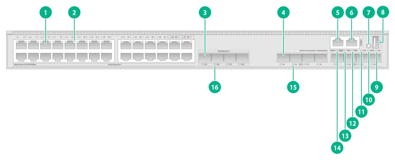
Figure2-17 Front panel
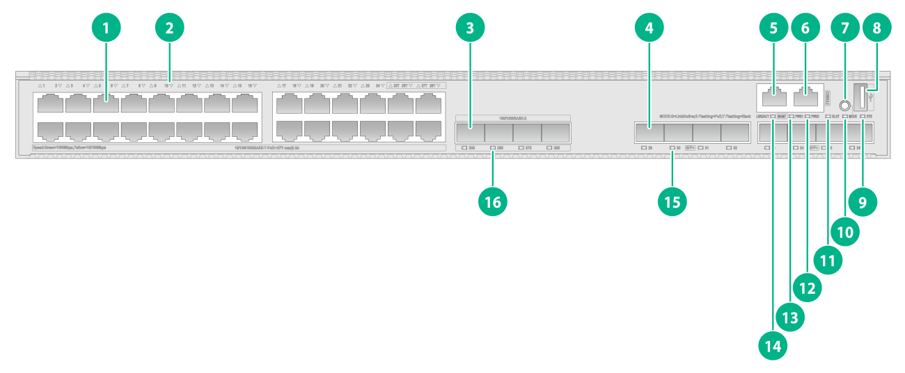
|
(1) 10/100/1000BASE-T autosensing Ethernet port |
(2) 10/100/1000BASE-T autosensing Ethernet port LED |
|
(3) SFP port |
(4) SFP+ port |
|
(5) Management Ethernet port (MGMT) |
(6) Console port (CONSOLE) |
|
(7) Mode button |
(8) USB port |
|
(9) System status LED (SYS) |
(10) Mode LED (MODE) |
|
(11) Expansion card status LED (SLOT) |
(12) Power supply 2 status LED (PWR2) |
|
(13) Power supply 1 status LED (PWR1) |
(14) Management Ethernet port LED (ACT/LINK) |
|
(15) SFP+ port LED |
(16) SFP port LED |

|
(1) Grounding screw |
(2) Expansion card |
|
(3) Fan tray 1 |
(4) Fan tray 2 |
|
(5) Power supply 1 |
(6) Power supply 2 |
The S5590-28P8XC-EI switch came with power supply slot 1 empty and power supply slot 2 installed with a filler panel. You can install one or two power supplies for the switch as required. In Figure2-18, two PSR600-54A-B AC power supplies are installed in the power supply slots.
The S5590-28P8XC-EI switch came with two fan tray slots empty. You must install two fan trays of the same model for the switch. In Figure2-18, two LSPM1FANSB-SN fan trays are installed in the fan tray slots.
The S5590-28P8XC-EI switch came with one expansion slot installed with a filler panel. You can select an expansion card for the switch as required. In Figure2-18, an LSWM2QP2P interface card is installed in the expansion slot.
The S5590-28P8XC-EI switch with PID LS-5590-28P8XC-EI-GL supports shipping with fan trays and power supplies installed. For the switch to be shipped with fan trays or power supplies installed, contact the marketing staff.
S5590-48P6XC-EI
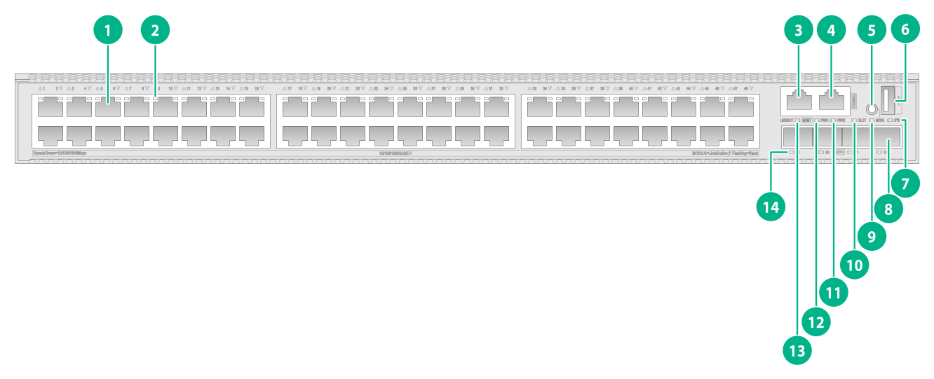
Figure2-19 Front panel
|
(1) 10/100/1000BASE-T autosensing Ethernet port |
(2) 10/100/1000BASE-T autosensing Ethernet port LED |
|
(3) SFP+ port |
(4) Console port (CONSOLE) |
|
(5) Mode LED (MODE) |
(6) System status LED (SYS) |
|
(7) Power supply 1 status LED (PWR1) |
(8) Power supply 2 status LED (PWR2) |
|
(9) Expansion card status LED (SLOT) |
(10) USB port |
|
(11) Mode button |
(12) Management Ethernet port LED (ACT/LINK) |
|
(13) Management Ethernet port (MGMT) |
(14) SFP+ port LED |
|
(1) Grounding screw |
(2) Expansion card |
|
(3) Fan tray 1 |
(4) Fan tray 2 |
|
(5) Power supply 1 |
(6) Power supply 2 |
The S5590-48P6XC-EI switch came with power supply slot 1 empty and power supply slot 2 installed with a filler panel. You can install one or two power supplies for the switch as required. In Figure2-20, two PSR600-54A-B AC power supplies are installed in the power supply slots.
The S5590-48P6XC-EI switch came with two fan tray slots empty. You must install two fan trays of the same model for the switch. In Figure2-20, two LSPM1FANSB-SN fan trays are installed in the fan tray slots.
The S5590-48P6XC-EI switch came with one expansion slot installed with a filler panel. You can select an expansion card for the switch as required. In Figure2-20, an LSWM2QP2P interface card is installed in the expansion slot.
The S5590-48P6XC-EI switch with PID LS-5590-48P6XC-EI-GL supports shipping with fan trays and power supplies installed. For the switch to be shipped with fan trays or power supplies installed, contact the marketing staff.
3 Removable components and compatibility matrixes
The switch supports removable components. Table3-1 describes the removable components available for the switch.
Table3-1 Compatibility matrix between switches and removable components
|
FRU model |
S5590-28T8XC-HI S5590-28S8XC-HI |
S5590-48T4XC-HI S5590-48S4XC-HI |
S5590-28T8XC-EI S5590-28S8XC-EI S5590-48T4XC-EI S5590-48S4XC-EI |
S5590-28P8XC-EI S5590-48P6XC-EI |
|
Removable power supplies |
||||
|
PSR250-12A |
Supported |
Supported |
Not supported |
Not supported |
|
PSR250-12A1 |
Supported |
Supported |
Not supported |
Not supported |
|
PSR180-12A-B |
Not supported |
Not supported |
Supported |
Not supported |
|
PSR180-12A-F |
Not supported |
Not supported |
Supported |
Not supported |
|
PSR180-12D-B |
Not supported |
Not supported |
Supported |
Not supported |
|
PSR600-54A-B |
Not supported |
Not supported |
Not supported |
Supported |
|
PSR920-54A-B |
Not supported |
Not supported |
Not supported |
Supported |
|
PSR1600-54A-B |
Not supported |
Not supported |
Not supported |
Supported |
|
Removable fan trays |
||||
|
LSPM1FANSA-SN |
Supported |
Supported |
Supported |
Supported |
|
LSPM1FANSB-SN |
Supported |
Supported |
Supported |
Supported |
|
Expansion cards |
||||
|
LSPM6FWD |
Supported |
Expansion cards supported by expansion slots 1 and 2 depend on the port rate mode. For more information, see Table3-2. |
Supported |
Supported |
|
LSWM2EC |
Supported |
Supported |
Supported |
|
|
LSWM2QP2P |
Supported |
Supported |
Supported |
|
|
LSWM2SP8P |
Supported |
Supported |
Supported |
|
|
LSWM2ZQP2P |
Supported |
Supported |
Supported |
|
|
LSWM2ZSP8P |
Supported |
Supported |
Supported |
|
|
LSWM2SP2PB |
Supported |
Supported |
Supported |
|
|
LSWM2SP4PB |
Supported |
Supported |
Supported |
|
Table3-2 Expansion card and expansion slot compatibility for the S5590-48T4XC-HI and S5590-48S4XC-HI switches
|
Expansion card |
S5590-48T4XC-HI S5590-48S4XC-HI |
|
|||||
|
Expansion slot 1 |
Expansion slot 2 |
||||||
|
mode0 |
mode1 |
mode2 |
mode0 |
mode1 |
mode2 |
||
|
LSPM6FWD |
Supported |
Not supported |
Supported |
Supported |
Supported |
Supported |
|
|
LSWM2EC |
Not supported |
Supported |
Supported |
Supported |
Supported |
Supported |
|
|
LSWM2QP2P |
Supported |
Not supported |
Supported |
Supported |
Supported |
Supported |
|
|
LSWM2SP2PB |
Not supported |
Supported |
Supported |
Supported |
Supported |
Supported |
|
|
LSWM2SP4PB |
Not supported |
Supported |
Supported |
Supported |
Supported |
Supported |
|
|
LSWM2SP8P |
Not supported |
Not supported |
Supported |
Supported |
Supported |
Supported |
|
|
LSWM2ZQP2P |
Not supported |
Not supported |
Not supported |
Supported |
Supported |
Supported |
|
|
LSWM2ZSP8P |
Not supported |
Not supported |
Not supported |
Supported |
Supported |
Supported |
|
The power supplies support asset management. You can use the display device manuinfo command to view the name, sequence number, and vendor of the power supply you have installed on the switch.
For non-PoE switches, you can install one power supply, or two power supplies for 1+1 redundancy on the switch.
For PoE switches, you can install one power supply, or two power supplies for 1+1 redundancy on the switch. PoE capabilities vary by power supply configuration. When a power supply fails, PoE capabilities of the switch might decrease. For more information about PoE power capacity, see Table1-5.
The switch uses removable fan trays. Do not power on the switch if it does not have two fan trays of the same model installed.
For the S5590-48T4XC-HI and S5590-48S4XC-HI switches, you can use the port-speed-mode command to configure the port rate mode for an expansion slot. By default, the port rate mode for an expansion slot is mode0. To have the configuration take effect, you must save the configuration and restart the switch. For more information about the port-speed-mode command, see Ethernet interface commands in the command reference for the switch.
The S5590-28P8XC-EI (LS-5590-28P8XC-EI-GL), S5590-48P6XC-EI (LS-5590-48P6XC-EI-GL), S5590-28S8XC-EI (LS-5590-28S8XC-EI-GL), and S5590-48S4XC-EI (LS-5590-48S4XC-EI-GL) switches support shipping with fan trays and power supplies installed. For the switch to be shipped with fan trays or power supplies installed, contact the marketing staff.
Removable power supplies
Table3-3 Power supplies available for the switch
|
Power supply model |
AC or DC input |
Specifications |
Reference |
|
PSR250-12A PSR250-12A1 |
AC input |
· Rated input voltage range: 100 to 240 VAC @ 50/60 Hz · Max input voltage range: 90 to 290 VAC @ 47 to 63 Hz · Max output power: 250 W |
H3C PSR250-12A & PSR250-12A1 Power Modules User Manual |
|
HVDC input |
· Rated input voltage: 240 VDC · Max input voltage range: 180 to 320 VDC · Max output power: 250 W |
||
|
PSR180-12A-B PSR180-12A-F |
AC input |
· Rated input voltage range: 100 to 240 VAC @ 50/60 Hz · Max input voltage range: 90 to 290 VAC @ 47 to 63 Hz · Max output power: 180 W |
H3C PSR180-12A & PSR180-12D Power Supply Series User Manual |
|
PSR180-12D-B |
DC input |
· Rated input voltage range: –48 to +60 VDC · Max input voltage range: –36 to +72 VDC · Max output power: 180 W |
|
|
PSR600-54A-B |
AC input |
· Rated input voltage range: 100 to 240 VAC @ 50/60 Hz · Max input voltage range: 90 to 290 VAC @ 47 to 63 Hz · Max output power: 600 W |
H3C PSR600-54A-B Power Module User Manual |
|
HVDC input |
· Rated input voltage: 240 VDC · Max input voltage range: 180 to 320 VDC · Max output power: 600 W |
||
|
PSR920-54A-B |
AC input |
· Rated input voltage range: ¡ 100 to 130 VAC @ 50/60 Hz ¡ 200 to 240 VAC @ 50/60 Hz · Max input voltage range: 90 to 290 VAC @ 47 to 63 Hz · Max output power: 920 W |
H3C PSR920-54A-B Power Module User Manual |
|
HVDC input |
· Rated input voltage: 240 VDC · Max input voltage range: 180 to 320 VDC · Max output power: 920 W |
||
|
PSR1600-54A-B |
AC input |
· Rated input voltage range: 100 to 240 VAC @ 50/60 Hz · Max input voltage range: 90 to 290 VAC @ 47 to 63 Hz · Max output power: ¡ 950 W: 90 to 176 VAC @ 47 to 63 Hz ¡ 1600 W: 176 to 290 VAC @ 47 to 63 Hz |
H3C PSR1600-54A-B Power Module User Manual |
|
HVDC input |
· Rated input voltage: 240 VDC · Max input voltage range: 180 to 320 VDC · Max output power: 1600 W |
Removable fan trays
Table3-4 Fan tray specifications
|
Fan tray model |
Item |
Specifications |
|
· LSPM1FANSA-SN (from the power supply side to the port side) · LSPM1FANSB-SN (from the port side to the power supply side) |
Dimensions (H × W × D) |
40 × 40.6 × 105 mm (1.57 × 1.60 × 4.13 in) |
|
Fan speed |
20000 R.P.M |
|
|
Max airflow |
20 CFM (0.57 m3/min) |
|
|
Input voltage |
12 V |
|
|
Power consumption |
9.8 W |
|
|
Documentation reference |
H3C LSPM1FANSA-SN & LSPM1FANSB-SN Fan Trays User Guide |
Expansion cards
Table3-5 Expansion cards
|
Item |
Specifications |
|
LSWM2QP2P |
|
|
Description |
2-port 40GE QSFP+ interface card |
|
Port type and quantity |
2 × 40 Gbps QSFP+ fiber ports |
|
Available transceiver modules and cables |
|
|
Reference |
H3C LSWM2QP2P Interface Card User Manual |
|
LSWM2SP8P |
|
|
Description |
8-port 10GE SFP+ interface card |
|
Port type and quantity |
8 × 10 Gbps SFP+ fiber ports |
|
Available transceiver modules and cables |
See 10GE SFP+ transceiver modules and cables described in Table4-8, Table4-9, and Table4-10 and GE SFP transceiver modules and cables described in Table4-6. |
|
Reference |
H3C LSWM2SP8PM & LSWM2SP8P Interface Cards User Manual |
|
LSWM2ZQP2P |
|
|
Description |
2-port 100GE QSFP28 interface module |
|
Port type and quantity |
2 × 40/100 Gbps QSFP28 fiber ports |
|
Available cables |
See QSFP28 transceiver modules and cables described in Table4-16, Table4-17, and Table4-18 and QSFP+ transceiver modules and cables described in Table4-13, Table4-14, and Table4-15. |
|
Reference |
H3C LSWM2ZQP2P Interface Card User Manual |
|
LSWM2ZSP8P |
|
|
Description |
8-port 25GE SFP28 interface module |
|
Port type and quantity |
8 × 25 Gbps SFP28 fiber ports |
|
Available transceiver modules and cables |
See SFP28 transceiver modules and cables described in Table4-11 and Table4-12 and 10GE SFP+ transceiver modules and cables described in Table4-8, Table4-9, and Table4-10. |
|
Reference |
H3C LSWM2ZSP8P Interface Card User Manual |
|
LSWM2EC |
|
|
Description |
The LSWM2EC EPS scanner module scans network-wide endpoints as instructed by the EPS server for port type and operating system type automatically and sends scanning results to the EPS server. Upon receiving the port information, the EPS server provides a baseline management over the endpoints that access the network system. By using this module on a switch, you can save hardware resources, increase the number of endpoints that can be scanned, and perform incremental scanning. |
|
Reference |
H3C LSWM2EC EPS Scanner Module User Manual |
|
LSPM6FWD |
|
|
Description |
The module is a fourth-generation high performance firewall module. It provides features including firewall, VPN, content filtering, content identification, URL filtering, and NAT. By using this module on a switch, you can enhance the switch security capabilities without changing the network topology. |
|
Reference |
H3C LSPM6FWD Card Manual |
|
LSWM2SP2PB |
|
|
Description |
2-port 10GE SFP+ interface module |
|
Port type and quantity |
2 × 1/10 Gbps SFP+ fiber ports |
|
Available transceiver modules and cables |
See 10GE SFP+ transceiver modules and cables described in Table4-8, Table4-9, and Table4-10 and GE SFP transceiver modules and cables described in Table4-6. |
|
Reference |
H3C LSWM2SP2PB & LSWM2SP4PB Interface Cards User Manual |
|
LSWM2SP4PB |
|
|
Description |
4-port 10GE SFP+ interface module |
|
Port type and quantity |
4 × 1/10 Gbps SFP+ fiber ports |
|
Available transceiver modules and cables |
See 10GE SFP+ transceiver modules and cables described in Table4-8, Table4-9, and Table4-10 and GE SFP transceiver modules and cables described in Table4-6. |
|
Reference |
H3C LSWM2SP2PB & LSWM2SP4PB Interface Cards User Manual |
|
|
NOTE: To use the LSWM2ZSP8P interface module, make sure the four lowest-numbered or four highest-numbered ports on the module have the same port rate and duplex mode. |
Connecting cables to the ports on expansion cards
To connect cables to the ports on expansion cards, follow these guidelines:
· Do not bundle cables in their first 20 m (65.62 ft).
· Separate power cords and twisted pair cables at and around the distribution frame.
· For ports adjacent to one another on the device, the peer ports on the distribution frame is preferably not adjacent, for example:
¡ If the device connects to one distribution frame, connect port 1 on the device to port 1 on the distribution frame and port 2 on the device to port 3 on the distribution frame.
¡ If the device connects to two distribution frames, connect port 1 on the device to port 1 on distribution frame 1 and port 2 on the device to port 1 on distribution frame 2.
· Keep the device and cables away from the interference source, such as a two-way radio and a high-power variable-frequency drive.
4 Ports and LEDs
Ports
Console port
Table4-1 Console port specifications
|
Item |
Specification |
|
Connector type |
RJ-45 |
|
Compliant standard |
EIA/TIA-232 |
|
Port transmission rate |
9600 bps (default) to 115200 bps |
|
Services |
· Provides connection to an ASCII terminal · Provides connection to the serial port of a local PC running terminal emulation program |
|
Compatible devices |
All device models |
Management Ethernet port
Table4-2 Management Ethernet port specifications
|
Item |
Specification |
|
Connector type |
RJ-45 |
|
Port transmission rate |
· 10 Mbps, half/full duplex · 100 Mbps, half/full duplex · 1000 Mbps, full duplex · MDI/MDI-X autosensing |
|
Transmission medium |
Category-5 or above twisted pair cable |
|
Max transmission distance |
100 m (328.08 ft) |
|
Compliant standard |
IEEE 802.3i, 802.3u, and 802.3ab |
|
Functions and services |
Switch software and Boot ROM upgrade, network management |
|
Compatible devices |
All device models |
USB port
Table4-3 USB port specifications
|
Item |
Specification |
|
Interface type |
USB 2.0 |
|
Compliant standard |
OHC |
|
Port transmission rate |
Uploads and downloads data at a rate up to 480 Mbps |
|
Functions and services |
Accesses the file system on the flash of the switch, for example, to upload or download application and configuration files |
|
Compatible devices |
All device models |
|
|
NOTE: USB devices from different vendors vary in compatibilities and drivers. H3C does not guarantee correct operation of USB devices from other vendors on the switch. If a USB device fails to operate on the switch, replace it with one from another vendor. |
SFP port
Table4-4 SFP port specifications
|
Item |
Specification |
|
Interface type |
SFP port |
|
Compatible transceiver modules and cables |
· FE SFP transceiver modules in Table4-5 · GE SFP transceiver modules and cables in Table4-6 |
|
Compatible devices |
All device models (excluding the S5590-48T4XC-HI, S5590-48T4XC-EI, and S5590-48P6XC-EI switches) |
|
Restrictions and guidelines |
When you use the SFP-GE-T or SFP-GE-T-D copper transceiver module, the interfaces can operate only at 1000 Mbps. |
Table4-5 FE SFP transceiver modules available for the SFP ports
|
FE SFP transceiver module |
Central wavelength (nm) |
Connector |
Fiber diameter (µm) |
Max transmission distance |
|
SFP-FE-SX-MM1310-A |
1310 |
LC |
Multi-mode, 50/125 |
2 km (1.24 miles) |
|
Multi-mode, 62.5/125 |
||||
|
SFP-FE-LX-SM1310-A |
1310 |
LC |
Single-mode, 9/125 |
15 km (9.32 miles) |
|
SFP-FE-LX-SM1310-D |
1310 |
LC |
Single-mode, 9/125 |
15 km (9.32 miles) |
|
SFP-FE-LH40-SM1310 |
1310 |
LC |
Single-mode, 9/125 |
40 km (24.86 miles) |
|
SFP-FE-LH80-SM1550 |
1550 |
LC |
Single-mode, 9/125 |
80 km (49.71 miles) |
|
SFP-FE-LX-SM1310-BIDI |
TX: 1310 RX: 1550 |
LC |
Single-mode, 9/125 |
15 km (9.32 miles) |
|
SFP-FE-LX-SM1550-BIDI |
TX: 1550 RX: 1310 |
LC |
Single-mode, 9/125 |
15 km (9.32 miles) |
|
|
IMPORTANT: The SFP-FE-LX-SM1310-BIDI and SFP-FE-LX-SM1550-BIDI transceiver modules must be used in pairs. For example, if one end uses the SFP-FE-LX-SM1310-BIDI transceiver module, the other end must use the SFP-FE-LX-SM1550-BIDI transceiver module. |
Table4-6 GE SFP transceiver modules and cables available for the SFP+ ports
|
GE SFP transceiver module and cable |
Central wavelength (nm) |
Connector |
Cable/Fiber type and diameter (µm) |
Modal bandwidth (MHz × km) |
Max transmission distance |
|
SFP copper transceiver modules |
|||||
|
SFP-GE-T |
N/A |
RJ-45 |
Twisted pair cable |
N/A |
100 m (328.08 ft) |
|
SFP-GE-T-D |
N/A |
RJ-45 |
Twisted pair cable |
N/A |
100 m (328.08 ft) |
|
SFP fiber transceiver modules |
|||||
|
SFP-GE-SX-MM850-A |
850 |
LC |
Multi-mode, 50/125 |
500 |
550 m (1804.46 ft) |
|
400 |
500 m (1640.42 ft) |
||||
|
Multi-mode, 62.5/125 |
200 |
275 m (902.23 ft) |
|||
|
160 |
220 m (721.78 ft) |
||||
|
SFP-GE-SX-MM850-D |
850 |
LC |
Multi-mode, 50/125 |
500 |
550 m (1804.46 ft) |
|
400 |
500 m (1640.42 ft) |
||||
|
Multi-mode, 62.5/125 |
200 |
275 m (902.23 ft) |
|||
|
160 |
220 m (721.78 ft) |
||||
|
SFP-GE-LX-SM1310-A |
1310 |
LC |
Single-mode, 9/125 |
N/A |
10 km (6.21 miles) |
|
Multi-mode, 50/125 |
500 or 400 |
550 m (1804.46 ft) |
|||
|
Multi-mode, 62.5/125 |
500 |
550 m (1804.46 ft) |
|||
|
SFP-GE-LH20-SM1310-I |
1310 |
LC |
Single-mode, 9/125 |
N/A |
20 km (12.43 miles) |
|
SFP-GE-LH40-SM1310-I |
1310 |
LC |
Single-mode, 9/125 |
N/A |
40 km (24.86 miles) |
|
SFP-GE-LH40-SM1310 |
1310 |
LC |
Single-mode, 9/125 |
N/A |
40 km (24.86 miles) |
|
SFP-GE-LH40-SM1310-D |
1310 |
LC |
Single-mode, 9/125 |
N/A |
40 km (24.86 miles) |
|
SFP-GE-LH40-SM1550 |
1550 |
LC |
Single-mode, 9/125 |
N/A |
40 km (24.86 miles) |
|
SFP-GE-LH80-SM1550 |
1550 |
LC |
Single-mode, 9/125 |
N/A |
80 km (49.71 miles) |
|
SFP-GE-LH80-SM1550-D |
1550 |
LC |
Single-mode, 9/125 |
N/A |
80 km (49.71 miles) |
|
SFP-GE-LH100-SM1550 |
1550 |
LC |
Single-mode, 9/125 |
N/A |
100 km (62.14 miles) |
|
SFP-GE-LX-SM1310-BIDI |
TX: 1310 RX: 1490 |
LC |
Single-mode, 9/125 |
N/A |
10 km (6.21 miles) |
|
SFP-GE-LX-SM1490-BIDI |
TX: 1490 RX: 1310 |
LC |
Single-mode, 9/125 |
N/A |
10 km (6.21 miles) |
|
SFP-GE-LH70-SM1490-BIDI |
TX: 1490 RX: 1550 |
LC |
Single-mode, 9/125 |
N/A |
70 km (43.50 miles) |
|
SFP-GE-LH70-SM1550-BIDI |
TX: 1550 RX: 1490 |
LC |
Single-mode, 9/125 |
N/A |
70 km (43.50 miles) |
|
SFP-GE-LH40-SM1310-BIDI |
TX: 1310 RX: 1550 |
LC |
Single-mode, 9/125 |
N/A |
40 km (24.86 miles) |
|
SFP-GE-LH40-SM1550-BIDI |
TX: 1550 RX: 1310 |
LC |
Single-mode, 9/125 |
N/A |
40 km (24.86 miles) |
|
SFP cable |
|||||
|
SFP-STACK-Kit |
N/A |
N/A |
N/A |
SFP cable |
1.5 m (4.92 ft) |
|
|
IMPORTANT: The SFP-GE-LX-SM1310-BIDI and SFP-GE-LX-SM1490-BIDI transceiver modules, SFP-GE-LH70-SM1550-BIDI and SFP-GE-LH70-SM1490-BIDI transceiver modules, and SFP-GE-LH40-SM1310-BIDI and SFP-GE-LH40-SM1550-BIDI transceiver modules must be used in pairs. For example, if one end uses the SFP-GE-LX-SM1310-BIDI transceiver module, the other end must use the SFP-GE-LX-SM1490-BIDI transceiver module. |
|
|
NOTE: · As a best practice, use H3C transceiver modules and network cables for the switch. · The H3C transceiver modules and network cables are subject to change over time. For the most recent list of H3C transceiver modules and cables, contact H3C Support or marketing staff. · For the specifications of H3C transceiver modules and network cables, see H3C Transceiver Modules User Guide. |
SFP+ port
Table4-7 SFP+ port specifications
|
Item |
Specification |
|
Interface type |
SFP+ port |
|
Compatible transceiver modules and cables |
· GE SFP transceiver modules and cables in Table4-6 · 10GE SFP+ transceiver modules and cables in Table4-8, Table4-9, and Table4-10 |
|
Compatible devices |
All device models and the LSWM2SP8P, LSWM2SP2PB, and LSWM2SP4PB expansion cards |
Table4-8 10GE SFP+ transceiver modules available for the SFP+ ports
|
10GE SFP+ transceiver module |
Central wavelength (nm) |
Connector |
Fiber diameter (µm) |
Modal bandwidth (MHz × km) |
Max transmission distance |
|
SFP-XG-SX-MM850-A |
850 |
LC |
Multi-mode, 50/125 |
2000 |
300 m (984.25 ft) |
|
500 |
82 m (269.03 ft) |
||||
|
400 |
66 m (216.54 ft) |
||||
|
Multi-mode, 62.5/125 |
200 |
33 m (108.27 ft) |
|||
|
160 |
26 m (85.30 ft) |
||||
|
SFP-XG-SX-MM850-D |
850 |
LC |
Multi-mode, 50/125 |
2000 |
300 m (984.25 ft) |
|
500 |
82 m (269.03 ft) |
||||
|
400 |
66 m (216.54 ft) |
||||
|
Multi-mode, 62.5/125 |
200 |
33 m (108.27 ft) |
|||
|
160 |
26 m (85.30 ft) |
||||
|
SFP-XG-LX-SM1310 |
1310 |
LC |
Single-mode, 9/125 |
N/A |
10 km (6.21 miles) |
|
SFP-XG-LX-SM1310-D |
1310 |
LC |
Single-mode, 9/125 |
N/A |
10 km (6.21 miles) |
|
SFP-XG-LX-SM1310-E |
1310 |
LC |
Single-mode, 9/125 |
N/A |
10 km (6.21 miles) |
|
SFP-XG-LH40-SM1550 |
1550 |
LC |
Single-mode, 9/125 |
N/A |
40 km (24.86 miles) |
|
SFP-XG-LH40-SM1550-D |
1550 |
LC |
Single-mode, 9/125 |
N/A |
40 km (24.86 miles) |
|
SFP-XG-LH80-SM1550 |
1550 |
LC |
Single-mode, 9/125 |
N/A |
80 km (49.71 miles) |
|
SFP-XG-LH80-SM1550-D |
1550 |
LC |
Single-mode, 9/125 |
N/A |
80 km (49.71 miles) |
|
SFP-XG-CPRI-IR-SM1310 |
1310 |
LC |
Single-mode, 9/125 |
N/A |
1.4 km (0.87 miles) |
|
SFP-XG-CPRI-LR-SM1310 |
1310 |
LC |
Single-mode, 9/125 |
N/A |
10 km (6.21 miles) |
|
SFP-XG-LH80-Tunable |
1547.75 |
LC |
Single-mode, 9/125 |
N/A |
80 km (49.71 miles) |
|
SFP-XG-LX-SM1270-BIDI |
TX: 1270 RX: 1330 |
LC |
Single-mode, 9/125 |
N/A |
10 km (6.21 miles) |
|
SFP-XG-LX-SM1330-BIDI |
TX: 1330 RX: 1270 |
LC |
Single-mode, 9/125 |
N/A |
10 km (6.21 miles) |
|
SFP-XG-LH40-SM1270-BIDI |
TX: 1270 RX: 1330 |
LC |
Single-mode, 9/125 |
N/A |
40 km (24.86 miles) |
|
SFP-XG-LH40-SM1330-BIDI |
TX: 1330 RX: 1270 |
LC |
Single-mode, 9/125 |
N/A |
40 km (24.86 miles) |
|
SFP-XG-LH80-SM1490-BIDI |
TX: 1490 RX: 1550 |
LC |
Single-mode, 9/125 |
N/A |
80 km (49.71 miles) |
|
SFP-XG-LH80-SM1550-BIDI |
TX: 1550 RX: 1490 |
LC |
Single-mode, 9/125 |
N/A |
80 km (49.71 miles) |
|
|
IMPORTANT: The SFP-XG-LX-SM1270-BIDI and SFP-XG-LX-SM1330-BIDI transceiver modules, SFP-XG-LH40-SM1270-BIDI and SFP-XG-LH40-SM1330-BIDI transceiver modules, and SFP-XG-LH80-SM1490-BIDI and SFP-XG-LH80-SM1550-BIDI transceiver modules must be used in pairs. For example, if one end uses an SFP-XG-LX-SM1270-BIDI transceiver module, the other end must use an SFP-XG-LX-SM1330-BIDI transceiver module. |
Table4-9 SFP+ copper cables available for the SFP+ ports
|
SFP+ copper cable |
Cable length |
|
LSWM1STK |
0.65 m (2.13 ft) |
|
LSWM2STK |
1.2 m (3.94 ft) |
|
LSWM3STK |
3 m (9.84 ft) |
|
LSTM1STK |
5 m (16.40 ft) |
Table4-10 SFP+ fiber cables available for the SFP+ ports
|
SFP+ fiber cable |
Cable length |
|
SFP-XG-D-AOC-7M |
7 m (22.97 ft) |
|
SFP-XG-D-AOC-10M |
10 m (32.81 ft) |
|
SFP-XG-D-AOC-20M |
20 m (65.62 ft) |
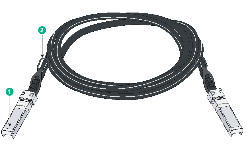
Figure4-1 SFP+ cable

|
(1) Connector |
(2) Pull latch |
|
|
NOTE: · As a best practice, use H3C transceiver modules and network cables for the switch. · The H3C transceiver modules and network cables are subject to change over time. For the most recent list of H3C transceiver modules and cables, contact H3C Support or marketing staff. · For the specifications of H3C transceiver modules and network cables, see H3C Transceiver Modules User Guide. |
SFP28 port
The LSWM2ZSP8P interface module provides SFP28 ports. To connect peer SFP28/SFP+ ports over a long distance, use SFP28/SFP+ transceiver modules and fibers. To connect peer SFP28/SFP+ ports over a short distance, use SFP28/SFP+ cables.
SFP28 ports support the following transceiver modules and cables:
· SFP28 transceiver modules in Table4-11.
· SFP28 cables in Table4-12.
· SFP+ transceiver modules in Table4-8.
· SFP+ copper cables in Table4-9.
· SFP+ fiber cables in Table4-10.
Table4-11 SFP28 transceiver modules available for the SFP28 ports
|
SFP28 transceiver module |
Central wavelength (nm) |
Connector |
Cable/Fiber type and diameter (µm) |
Modal bandwidth (MHz × km) |
Max transmission distance |
|
SFP-25G-SR-MM850 |
850 |
LC |
Multi-mode, 50/125 |
2000 |
70 m (229.66 ft) |
|
4700 |
100 m (328.08 ft) |
||||
|
SFP-25G-LR-SM1310 |
1310 |
LC |
Single-mode, 9/125 |
N/A |
10 km (6.21 miles) |
|
SFP-25G-LR-SM1310-I |
1310 |
LC |
Single-mode, 9/125 |
N/A |
10 km (6.21 miles) |
Table4-12 SFP28 cables available for the SFP28 ports
|
SFP28 cable |
Cable length |
|
SFP-25G-D-CAB-1M |
1 m (3.28 ft) |
|
SFP-25G-D-CAB-3M |
3 m (9.84 ft) |
|
SFP-25G-D-CAB-5M |
5 m (16.40 ft) |
|
SFP-25G-D-AOC-3M |
3 m (9.84 ft) |
|
SFP-25G-D-CAB-4M-A |
4 m (13.12 ft) |
|
SFP-25G-D-AOC-5M |
5 m (16.40 ft) |
|
SFP-25G-D-AOC-7M |
7 m (22.97 ft) |
|
SFP-25G-D-AOC-10M |
10 m (32.81 ft) |
|
SFP-25G-D-AOC-20M |
20 m (65.62 ft) |
|
(1) Connector |
(2) Pull latch |
|
|
NOTE: · As a best practice, use H3C transceiver modules and cables for the switch. · The H3C transceiver modules and cables are subject to change over time. For the most recent list of H3C transceiver modules and cables, contact your H3C Support or marketing staff. · For more information about H3C transceiver modules and cables, see H3C Transceiver Modules User Guide. |
QSFP+ port
The LSWM2QP2P interface card provides two QSFP+ ports. You can install the QSFP+ transceiver modules in Table4-13, QSFP+ copper cables in Table4-14, and QSFP+ fiber cables in Table4-15.
Table4-13 QSFP+ transceiver modules available for the QSFP+ ports
|
QSFP+ transceiver module |
Central wavelength (nm) |
Connector |
Fiber type and diameter (µm) |
Modal bandwidth (MHz × km) |
Max transmission distance |
|
QSFP-40G-SR4-MM850 |
850 |
MPO |
Multi-mode, 50/125 |
2000 |
100 m (328.08 ft) |
|
4700 |
150 m (492.13 ft) |
||||
|
QSFP-40G-CSR4-MM850 |
850 |
MPO |
Multi-mode, 50/125 |
2000 |
300 m (984.25 ft) |
|
4700 |
400 m (1312.34 ft) |
||||
|
QSFP-40G-BIDI-SR-MM850 |
Two lanes: · 850 · 900 |
LC |
Multi-mode, 50/125 |
2000 |
100 m (328.08 ft) |
|
4700 |
150 m (492.13 ft) |
||||
|
QSFP-40G-BIDI-WDM850 |
Four lanes: · 850 · 880 · 910 · 940 |
LC |
Multi-mode, 50/125 |
2000 |
240 m (787.40 ft) |
|
4700 |
350 m (1148.29 ft) |
||||
|
QSFP-40G-LR4-WDM1300 |
Four lanes: · 1271 · 1291 · 1311 · 1331 |
LC |
Single-mode, 9/125 |
N/A |
10 km (6.21 miles) |
|
QSFP-40G-LR4L-WDM1300 |
Four lanes: · 1271 · 1291 · 1311 · 1331 |
LC |
Single-mode, 9/125 |
N/A |
2 km (1.24 miles) |
|
QSFP-40G-ER4-WDM1300 |
Four lanes: · 1271 · 1291 · 1311 · 1331 |
LC |
Single-mode, 9/125 |
N/A |
40 km (24.86 miles) |
Table4-14 40G QSFP+ copper cables available for the QSFP+ ports
|
QSFP+ copper cable |
Max transmission distance |
|
LSWM1QSTK0 |
1 m (3.28 ft) |
|
LSWM1QSTK1 |
3 m (9.84 ft) |
|
LSWM1QSTK2 |
5 m (16.40 ft) |
Table4-15 40G QSFP+ fiber cables available for the QSFP+ ports
|
QSFP+ fiber cable |
Max transmission distance |
|
QSFP-40G-D-AOC-3M |
3 m (9.84 ft) |
|
QSFP-40G-D-AOC-7M |
7 m (22.97 ft) |
|
QSFP-40G-D-AOC-10M |
10 m (32.81 ft) |
|
QSFP-40G-D-AOC-20M |
20 m (65.62 ft) |
Figure4-3 40G QSFP+ cable
|
(1) Connector |
(2) Pull tab |
|
|
NOTE: · As a best practice, use H3C transceiver modules and cables for the switch. · The H3C transceiver modules and cables are subject to change over time. For the most recent list of H3C transceiver modules and cables, contact your H3C Support or marketing staff. · For more information about H3C transceiver modules and cables, see H3C Transceiver Modules User Guide. |
QSFP28 ports
The LSWM2ZQP2P interface module provides two QSFP28 ports.
QSFP28 ports support the following transceiver modules and cables:
· QSFP28 transceiver modules in Table4-16.
· QSFP28 fiber cables in Table4-17.
· QSFP28 fiber cables in Table4-18.
· QSFP+ transceiver modules in Table4-13.
· QSFP+ copper cables in Table4-14.
· QSFP+ fiber cables in Table4-15.
Table4-16 QSFP28 transceiver modules available for the QSFP28 ports
|
QSFP28 transceiver module |
Central wavelength (nm) |
Connector |
Fiber type and diameter (µm) |
Modal bandwidth (MHz*km) |
Maximum transmission distance |
|
QSFP-100G-SR4-MM850 |
850 |
MPO |
Multimode, 50/125 |
2000 |
70 m (229.66 ft) |
|
4700 |
100 m (328.08 ft) |
||||
|
QSFP-100G-eSR4-MM850 |
850 |
MPO |
Multimode, 50/125 |
4700 |
300 m (984.25 ft) |
|
QSFP-100G-PSM4-SM1310 |
1310 |
MPO |
Single mode, 9/125 |
N/A |
0.5 km (0.31 miles) |
|
QSFP-100G-LR4-WDM1300 |
Four lanes: · 1295.56 · 1300.05 · 1304.58 · 1309.14 |
LC |
Single mode, 9/125 |
N/A |
10 km (6.21 miles) |
|
QSFP-100G-LR4L-WDM1300 |
Four lanes: · 1271 · 1291 · 1311 · 1331 |
LC |
Single mode, 9/125 |
N/A |
2 km (1.24 miles) |
|
QSFP-100G-ER4L-WDM1300 |
Four lanes: · 1295 · 1300 · 1304 · 1309 |
LC |
Single mode, 9/125 |
N/A |
40 km (24.86 miles) |
Table4-17 100G QSFP28 fiber cables available for the QSFP28 ports
|
QSFP28 fiber cable |
Cable length |
|
QSFP-100G-D-AOC-7M |
7 m (22.97 ft) |
|
QSFP-100G-D-AOC-10M |
10 m (32.81 ft) |
|
QSFP-100G-D-AOC-20M |
20 m (65.62 ft) |
Table4-18 100G QSFP28 copper cables available for the QSFP28 ports
|
QSFP28 copper cable |
Cable length |
|
QSFP-100G-D-CAB-1M |
1 m (3.28 ft) |
|
QSFP-100G-D-CAB-3M |
3 m (9.84 ft) |
|
QSFP-100G-D-CAB-5M |
5 m (16.40 ft) |
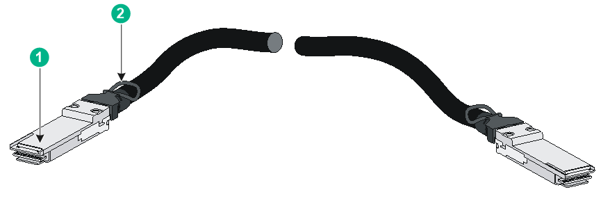
Figure4-4 100G QSFP28 copper cable

|
(1) Connector |
(2) Pull tab |
|
|
NOTE: · As a best practice, use H3C transceiver modules and cables for the switch. · The H3C transceiver modules and cables are subject to change over time. For the most recent list of H3C transceiver modules and cables, contact your H3C Support or marketing staff. · For more information about H3C transceiver modules and cables, see H3C Transceiver Modules User Guide. |
10/100/1000BASE-T Ethernet port
Table4-19 10/100/1000BASE-T Ethernet port specifications
|
Item |
Specification |
|
Connector type |
RJ-45 |
|
Rate, duplex mode, and auto-MDI/MDI-X |
· 10 Mbps, half/full duplex · 100 Mbps, half/full duplex · 1000 Mbps, full duplex · MDI/MDI-X autosensing |
|
Max transmission distance |
100 m (328.08 ft) |
|
Transmission medium |
Category 5 or above twisted pair cable |
|
Compliant standard |
IEEE 802.3i, 802.3u, and 802.3ab |
|
Compatible devices |
All device models (excluding the S5590-48S4XC-HI and S5590-48S4XC-EI switches) |
Combo interface
The S5590-28T8XC-HI, S5590-28S8XC-HI, S5590-28T8XC-EI, S5590-28S8XC-EI, and S5590-28P8XC-EI switches each provide four combo interfaces on the front panel. A combo interface contains an SFP port and a 10/100/1000BASE-T autosensing Ethernet port. Only one of these two ports can operate at a time.
LEDs
System status LED
The system status LED shows the operating status of the switch.
Table4-20 System status LED description
|
LED mark |
Status |
Description |
|
SYS |
Steady green |
The switch has started correctly. |
|
Flashing green (1 Hz) |
The switch is performing power-on self test (POST). |
|
|
Steady red |
The switch has failed the POST or is faulty. |
|
|
Off |
The switch is powered off. |
Power status LED
For the S5590-EI switch series, the power status LED shows the operating status of a power supply.
Table4-21 Power status LED description
|
LED mark |
Status |
Description |
|
PWR1/PWR2 |
Steady green |
The power supply is operating correctly. |
|
Steady yellow |
The power supply is present, but it is not operating or is faulty. |
|
|
Off |
No power supply is present. |
Mode LED
The mode LED (MODE) works in conjunction with the port status LEDs to show more information about the switch.
The mode LED indicates the type of information that the port status LEDs are showing.
After you press the mode button to change the mode LED status into flashing green or flashing yellow, the mode LED keeps in that state for only 45 seconds and then turns steady green automatically.
Table4-22 Mode LED description
|
LED mark |
Status |
Description |
|
MODE |
Steady green |
The port status LEDs indicate link state of the ports. |
|
Flashing green (available only for PoE switches) |
The port status LEDs indicate the PoE status of the ports. |
|
|
Flashing yellow |
The port status LEDs indicate the IRF member ID of the switch. For example, if the LEDs for ports 1 to 4 are steady green and the others are off, the IRF member ID of the switch is 4. |
Management Ethernet port LED
Table4-23 Management Ethernet port LED description
|
Management Ethernet port LED status |
Description |
|
Steady green |
A link is present on the port. |
|
Flashing yellow |
The port is sending or receiving data. |
|
Off |
No link is present on the port. |
10/100/1000BASE-T autosensing Ethernet port LED
The 10/100/1000BASE-T autosensing Ethernet port LEDs work in conjunction with the mode LED to indicate the operating status of the ports from different aspects, as shown in Table4-24.
Table4-24 10/100/1000BASE-T autosensing Ethernet port LED description
|
Mode LED (MODE) status |
Ethernet port LED status |
Description |
|
Steady green (rate mode) |
Steady green |
The port is operating at 10/100/1000 Mbps. |
|
Flashing green |
The port is sending or receiving data at 10/100/1000 Mbps. |
|
|
Off |
No link is present on the port. |
|
|
Flashing green (PoE mode, available only for PoE switches) |
Steady green |
PoE power supply is normal. |
|
Flashing green (1 Hz) |
· The maximum PoE power provided by the port does not meet the power requirement of the PD. · PoE power supply overcurrent, overvoltage, or short-circuit has occurred. · The remaining power of the switch does not meet the power supply requirement of the port. |
|
|
Off |
The port is not connected to a PD or PoE is not enabled on the port. |
|
|
Flashing yellow (IRF mode) |
Steady green |
The autosensing Ethernet port LEDs on the switch work in conjunction to indicate the IRF member ID of the switch. For example, if the LEDs for ports 1 to 4 are steady green and the others are off, the IRF member ID of the switch is 4. |
SFP port LED
The SFP port LEDs work in conjunction and the mode LED to indicate the operating status of SFP ports.
Table4-25 SFP port LED description
|
Mode LED (MODE) status |
SFP port LED status |
Description |
|
Steady green (rate mode) |
Steady green |
The port is operating at 100/1000 Mbps. |
|
Flashing green |
The port is sending or receiving data at 100/1000 Mbps. |
|
|
Off |
No link is present on the port. |
|
|
Flashing yellow (IRF mode) |
Steady green |
The SFP port LEDs on the switch work in conjunction to indicate the IRF member ID of the switch. For example, if the LEDs for ports 1 to 4 are steady green and the others are off, the IRF member ID of the switch is 4. |
SFP+ port LED
Table4-26 SFP+ port LED description
|
Mode LED status |
SFP+ port LED status |
Description |
|
Steady green (rate mode) |
Steady green |
The port is operating at 1/10 Gbps. |
|
Flashing green |
The port is sending or receiving data at 1/10 Gbps. |
|
|
Off |
No link is present on the port. |
|
|
Flashing green (PoE mode, available only for PoE switches) |
Off |
The mode LED (MODE) is operating in PoE mode. |
|
Flashing yellow (IRF mode) |
Off |
When the mode LED (MODE) is flashing yellow (IRF mode), the SFP+ port LEDs are off. |
Expansion card status LED
The S5590-HI switch series provides two expansion slots at the rear. The S5590-EI switch series provides one expansion slot at the rear. The expansion card status LED on the front panel indicates the operating status of the expansion card.
Table4-27 Expansion card status LED description
|
LED mark |
Status |
Description |
|
SLOT/SLOT1/SLOT2 |
Steady green |
The expansion card is operating correctly. |
|
Flashing yellow |
The switch does not support the expansion card model, or the expansion card is faulty. |
|
|
Off |
The expansion slot is empty. |
Port status LED on the expansion card
The expansion cards provide a port status LED for each port. For more information, see the user manual for the expansion card.
Status LED on a power supply
The PSR250-12A, PSR250-12A1, PSR600-54A-B, PSR920-54A-B, and PSR1600-54A-B power supplies each have a LED to indicate the power supply operating status. For more information, see the user manual for the power supply.
Fan tray status LED on a fan tray
The LSPM1FANSA-SN and LSPM1FANSB-SN fan trays each have a LED to indicate the fan tray operating status.
Table4-28 Fan tray status LED description
|
Status |
Description |
|
On |
The fan tray is faulty. |
|
Off |
The fan tray is operating correctly. |
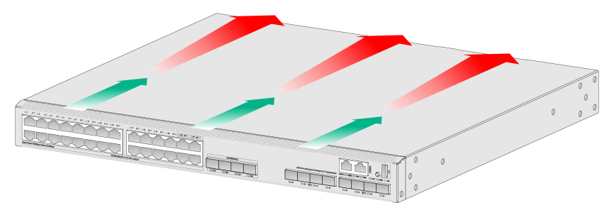
5 Cooling system
To dissipate heat timely and enhance system stability, the switch uses a high-performance cooling system. Consider the site ventilation design when you plan the installation site for the switch.
The switch uses removable fan trays and provides airflow from the port side to the power supply side or from the power supply side to the port side by using different types of fan trays. You must install both fan trays of the same model for the switch. Table5-1 describes the fan trays available for the switch.
Table5-1 Fan trays available for the switch
|
Switch model |
Fan tray model |
Airflow direction |
|
S5590-28T8XC-HI S5590-48T4XC-HI S5590-28S8XC-HI S5590-48S4XC-HI S5590-28T8XC-EI S5590-48T4XC-EI S5590-28S8XC-EI S5590-48S4XC-EI S5590-28P8XC-EI S5590-48P6XC-EI |
LSPM1FANSA-SN |
From the power supply side to the port side |
|
LSPM1FANSB-SN |
From the port side to the power supply side |
Figure5-1 Airflow direction for LSPM1FANSA-SN (S5590-28P8XC-EI)
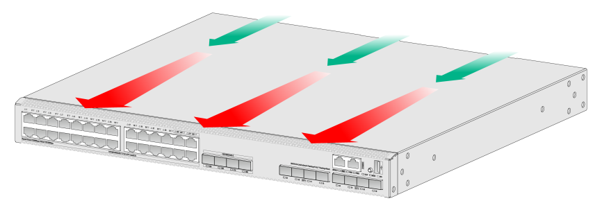
Figure5-2 Airflow direction for LSPM1FANSB-SN (S5590-28P8XC-EI)