- Table of Contents
- Related Documents
-
| Title | Size | Download |
|---|---|---|
| 01-Hardware Information and Specifications | 2.23 MB |
Product models and technical specifications
10/100/1000BASE-T autosensing Ethernet port
2.5G/1000/100BASE-T autosensing Ethernet port
10/100/1000BASE-T autosensing Ethernet port LED
2.5G/1000/100BASE-T autosensing Ethernet port LED
1000/100BASE-T autosensing Ethernet port LED
Product models and technical specifications
Product models
This document provides an installation guide for the following switch series
· S5120V3-EI switch series
· S5120V3-LI switch series
· S5120V3-SI switch series
Table 1 describes the switch models that each switch series includes.
Table 1 Switch series and models
|
Switch series |
Model |
Product code (PID) |
|
|
S5120V3-EI switch series |
Non-PoE models |
S5120V3-28S-EI |
LS-5120V3-28S-EI |
|
S5120V3-54S-EI |
LS-5120V3-54S-EI |
||
|
S5120V3-28P-EI |
LS-5120V3-28P-EI |
||
|
S5120V3-54P-EI |
LS-5120V3-54P-EI |
||
|
S5120V3-36F-EI |
LS-5120V3-36F-EI |
||
|
PoE models |
S5120V3-28S-HPWR-EI |
LS-5120V3-28S-HPWR-EI |
|
|
S5120V3-54S-PWR-EI |
LS-5120V3-54S-PWR-EI |
||
|
S5120V3-30MS-UPWR-DP-EI |
LS-5120V3-30MS-UPWR-DP-EI |
||
|
S5120V3-LI switch series |
Non-PoE models |
S5120V3-10P-LI |
LS-5120V3-10P-LI LS-5120V3-10P-LI-GL |
|
S5120V3-20P-LI |
LS-5120V3-20P-LI LS-5120V3-20P-LI-GL |
||
|
S5120V3-28S-LI |
LS-5120V3-28S-LI LS-5120V3-28S-LI-GL |
||
|
S5120V3-28P-LI |
LS-5120V3-28P-LI LS-5120V3-28P-LI-GL |
||
|
S5120V3-52S-LI |
LS-5120V3-52S-LI LS-5120V3-52S-LI-GL |
||
|
S5120V3-52P-LI |
LS-5120V3-52P-LI LS-5120V3-52P-LI-GL |
||
|
PoE models |
S5120V3-28S-PWR-LI |
LS-5120V3-28S-PWR-LI LS-5120V3-28S-PWR-LI-GL |
|
|
S5120V3-28P-PWR-LI |
LS-5120V3-28P-PWR-LI LS-5120V3-28P-PWR-LI-GL |
||
|
S5120V3-52S-PWR-LI |
LS-5120V3-52S-PWR-LI LS-5120V3-52S-PWR-LI-GL |
||
|
S5120V3-52P-PWR-LI |
LS-5120V3-52P-PWR-LI LS-5120V3-52P-PWR-LI-GL |
||
|
S5120V3-28P-HPWR-LI-Q |
LS-5120V3-28P-HPWR-LI-Q |
||
|
S5120V3-28P-HPWR-LI |
LS-5120V3-28P-HPWR-LI LS-5120V3-28P-HPWR-LI-GL |
||
|
S5120V3-28S-HPWR-LI |
LS-5120V3-28S-HPWR-LI LS-5120V3-28S-HPWR-LI-GL |
||
|
S5120V3-10P-PWR-LI |
LS-5120V3-10P-PWR-LI LS-5120V3-10P-PWR-LI-GL |
||
|
S5120V3-12TP-HPWR-LI |
LS-5120V3-12TP-HPWR-LI |
||
|
S5120V3-SI switch series |
Non-PoE models |
S5120V3-10P-SI |
LS-5120V3-10P-SI |
|
S5120V3-28P-SI |
LS-5120V3-28P-SI |
||
|
S5120V3-28S-SI |
LS-5120V3-28S-SI |
||
|
S5120V3-52P-SI |
LS-5120V3-52P-SI |
||
|
S5120V3-52S-SI |
LS-5120V3-52S-SI |
||
|
S5120V3-36F-SI |
LS-5120V3-36F-SI |
||
|
PoE models |
S5120V3-28P-HPWR-SI |
LS-5120V3-28P-HPWR-SI |
|
|
S5120V3-54P-PWR-SI |
LS-5120V3-54P-PWR-SI |
||
|
S5120V3-28S-HPWR-SI-Q |
LS-5120V3-28S-HPWR-SI-Q |
||
|
|
NOTE Switches of the same model but different PIDs might differ in hardware and software features. You can view the PID of a switch on the label located on its rear panel or top panel. |
Technical specifications
S5120V3-EI switch series
Table 2 Technical specifications for the S5120V3-EI non-PoE switch models
|
Item |
S5120V3-28S-EI |
S5120V3-54S-EI |
S5120V3-28P-EI |
S5120V3-54P-EI |
S5120V3-36F-EI |
|
|
Dimensions (H × W × D) |
43.6 × 440 × 160 mm (1.72 × 17.32 × 6.30 in) |
43.6 × 440 × 260 mm (1.72 × 17.32 × 10.24 in) |
43.6 × 440 × 160 mm (1.72 × 17.32 × 6.30 in) |
43.6 × 440 × 260 mm (1.72 × 17.32 × 10.24 in) |
43.6 × 440 × 260 mm (1.72 × 17.32 × 10.24 in) |
|
|
Weight |
≤ 2.2 kg (4.85 lb) |
≤ 4.0 kg (8.82 lb) |
≤ 2.2 kg (4.85 lb) |
≤ 4.0 kg (8..82 lb) |
≤ 3.5 kg (7.72 lb) |
|
|
Console port |
1 × serial console port |
1 × serial console port |
1 × serial console port |
1 × serial console port |
1 × serial console port |
|
|
SFP+ port |
4 |
6 |
N/A |
N/A |
4 |
|
|
SFP port |
N/A |
N/A |
4 |
6 |
24 |
|
|
10/100/1000BASE-T autosensing Ethernet port |
24 |
48 |
24 |
48 |
8 |
|
|
Input voltage |
· Rated voltage 100 VAC to 240 VAC @ 50 or 60 Hz · Max voltage 90 VAC to 264 VAC @ 47 to 63 Hz |
|||||
|
Minimum power consumption |
17 W |
19 W |
17 W |
23 W |
27 W |
|
|
Maximum power consumption |
37 W |
53 W |
36 W |
52 W |
54 W |
|
|
Chassis leakage current compliance |
UL 62368-1/EN 62368-1/IEC 62368-1/UL 60950-1/IEC 60950-1/GB4943.1 |
|||||
|
Melting current of power supply fuse |
2 A/250 V |
3.15 A/250 V |
2 A/250 V |
3.15 A/250 V |
3.15 A/250 V |
|
|
Operating temperature |
–5°C to +45°C (23°F to 113°F) |
|||||
|
Operating humidity |
5% RH to 95% RH, noncondensing |
|||||
|
Fire resistance compliance |
UL 62368-1/EN 62368-1/IEC 62368-1/UL 60950-1/IEC 60950-1/GB4943.1 |
|||||
Table 3 Technical specifications for S5120V3-EI PoE switch models
|
Item |
S5120V3-28S-HPWR-EI |
S5120V3-54S-PWR-EI |
S5120V3-30MS-UPWR-DP-EI |
|
Dimensions (H × W × D) |
43.6 × 440 × 320 mm (1.72 × 17.32 × 12.60 in) |
43.6 × 440 × 320 mm (1.72 × 17.32 × 12.60 in) |
43.6 × 440 × 460 mm (1.72 × 17.32 × 18.11 in) |
|
Weight |
≤ 5 kg (11.02 lb) |
≤ 5.5 kg (12.13 lb) |
≤ 8.5 kg (18.74 lb) |
|
Console port |
1 × serial console port |
1 × serial console port |
1 × serial console port |
|
SFP+ port |
4 |
6 |
6 |
|
2.5G/100/1000BASE-T autosensing Ethernet port |
N/A |
N/A |
16 |
|
1000/100BASE-T autosensing Ethernet port |
N/A |
N/A |
8 |
|
10/100/1000BASE-T autosensing Ethernet port |
24 |
48 |
N/A |
|
Input voltage |
AC input · Rated voltage 100 VAC to 240 VAC @ 50 or 60 Hz · Max voltage 90 VAC to 264 VAC @ 47 to 63 Hz |
· AC input for the PSR360-56A/PSR720-56A power supply ¡ Rated voltage range 100 VAC to 240 VAC @ 50 Hz or 60 Hz ¡ Max voltage range 90 VAC to 264 VAC @ 47 Hz to 63 Hz · AC input for the PSR1110-56A power supply ¡ Rated voltage range 115 VAC to 240 VAC @ 50 Hz or 60 Hz ¡ Max voltage range 102.5 VAC to 264 VAC @ 47 Hz to 63 Hz · DC input for the PSR560-56D power supply ¡ Rated voltage range –48 VDC to –60 VDC ¡ Max voltage range –36 VDC to –72 VDC |
|
|
Maximum PoE power per port |
30 W |
30 W |
Depends on the power supply configuration, as shown in Table 4. |
|
Total PoE power |
370 W |
370W |
|
|
Minimum power consumption |
24 W |
30 W |
· Single AC input: 47 W · Dual AC inputs: 56 W · Single DC input: 45 W · Dual DC inputs: 64 W |
|
Maximum power consumption |
460 W |
470 W |
· Single AC input: 1270 W · Dual AC inputs: 2430 W · Single DC input: 670 W · Dual DC inputs: 1350 W |
|
Power efficiency |
80 PLUS Gold |
N/A |
|
|
Chassis leakage current compliance |
UL 62368-1/EN 62368-1/IEC 62368-1/UL 60950-1/IEC 60950-1/GB4943.1 |
||
|
Melting current of power supply fuse |
10 A/250 V |
· PSR360-56A: 10 A/250 V · PSR720-56A: 10 A/250 V · PSR1110-56A: 15 A/250 V · PSR560-56D: 30 A/250 V |
|
|
Operating temperature |
–5°C to +45°C (23°F to 113°F) |
||
|
Operating humidity |
5% RH to 95% RH, noncondensing |
||
|
Fire resistance compliance |
UL 62368-1/EN 62368-1/IEC 62368-1/UL 60950-1/IEC 60950-1/GB4943.1 |
||
Table 4 PoE power capacity of the S5120V3-30MS-UPWR-DP-EI switch
|
Power supply configuration |
S5120V3-30MS-UPWR-DP-EI |
|
|
Total PoE power capacity |
Max PoE power capacity per port |
|
|
2 × PSR1110-56A |
2140 W |
90 W |
|
1 × PSR1110-56A and 1 × PSR720-56A |
1750 W |
90 W |
|
1 × PSR1110-56A and 1 × PSR560-56D |
1590 W |
90 W |
|
1 × PSR1110-56A and 1 × PSR360-56A |
1390 W |
90 W |
|
1 × PSR1110-56A |
1040 W |
90 W |
|
2 × PSR720-56A |
1360 W |
90 W |
|
1 × PSR720-56A and 1 × PSR560-56D |
1200 W |
90 W |
|
1 × PSR720-56A and 1 × PSR360-56A |
1000 W |
90 W |
|
1 × PSR720-56A |
650 W |
90 W |
|
2 × PSR560-56D |
1040 W |
90 W |
|
1 × PSR560-56D and 1 × PSR360-56A |
840 W |
90 W |
|
1 × PSR560-56D |
490 W |
90 W |
|
2 × PSR360-56A |
640 W |
90 W |
|
1 × PSR360-56A |
290 W |
90 W |
S5120V3-LI switch series
Table 5 Technical specifications for S5120V3-LI non-PoE switch models
|
Item |
S5120V3-10P-LI |
S5120V3-20P-LI |
S5120V3-28P-LI |
S5120V3-28S-LI |
S5120V3-52P-LI |
S5120V3-52S-LI |
|
Dimensions (H × W × D) |
43.6 × 266 × 161 mm (1.72 × 10.47 × 6.34 in) |
43.6 × 330 × 230 mm (1.72 × 12.99 × 9.06 in) |
43.6 × 440 × 160 mm (1.72 × 17.32 × 6.30 in) |
43.6 × 440 × 160 mm (1.72 × 17.32 × 6.30 in)4 |
43.6 × 440 × 230 mm (1.72 × 17.32 × 9.06 in)4 |
43.6 × 440 × 230 mm (1.72 × 17.32 × 9.06 in)4 |
|
Weight |
≤ 1.5 kg (3.31 lb) |
≤ 2 kg (4.41 lb) |
≤ 2.5 kg (5.51 lb) |
≤ 2.5 kg (5.51 lb) |
≤ 3.5 kg (7.72 lb) |
≤ 3.5 kg (7.72 lb) |
|
Console port |
1 × serial console port |
1 × serial console port |
1 × serial console port |
1 × serial console port |
1 × serial console port |
1 × serial console port |
|
SFP port |
2 |
4 |
4 |
N/A |
4 |
N/A |
|
SFP+ port |
N/A |
N/A |
N/A |
4 |
N/A |
4 |
|
10/100/1000BASE-T autosensing Ethernet port |
8 |
16 |
24 |
24 |
48 |
48 |
|
Input voltage |
AC input · Rated voltage 100 VAC to 240 VAC @ 50 or 60 Hz · Max voltage 90 VAC to 264 VAC @ 47 to 63 Hz |
|||||
|
Minimum power consumption |
8 W |
9 W |
9 W |
10 W |
18 W |
19 W |
|
Maximum PoE power per port |
14 W |
19 W |
23 W |
24 W |
41 W |
44 W |
|
Chassis leakage current compliance |
UL 62368-1/EN 62368-1/IEC 62368-1/UL 60950-1/IEC 60950-1/GB4943.1 |
|||||
|
Melting current of power supply fuse |
2 A/250 V |
2 A/250 V |
2 A/250 V |
2 A/250 V |
3.15 A/250 V |
3.15 A/250 V |
|
Operating temperature |
–5°C to +45°C (23°F to 113°F) |
|||||
|
Operating humidity |
5% RH to 95% RH, noncondensing |
|||||
|
Fire resistance compliance |
UL 62368-1/EN 62368-1/IEC 62368-1/UL 60950-1/IEC 60950-1/GB4943.1 |
|||||
Table 6 Technical specifications for the S5120V3-LI PoE switch models(1)
|
Item |
S5120V3-28P-PWR-LI |
S5120V3-28S-PWR-LI |
S5120V3-52P-PWR-LI |
S5120V3-52S-PWR-LI |
S5120V3-28P-HPWR-LI-Q |
|
|
Dimensions (H × W × D) |
43.6 × 440 × 260 mm (1.72 × 17.32 × 10.24 in) |
43.6 × 440 × 260 mm (1.72 × 17.32 × 10.24 in) |
43.6 × 440 × 400 mm (1.72 × 17.32 × 15.75 in) |
43.6 × 440 × 400 mm (1.72 × 17.32 × 15.75 in) |
43.6 × 440 × 422 mm (1.72 × 17.32 × 16.61 in) |
|
|
Weight |
≤ 4.5 kg (9.92 lb) |
≤ 4.5 kg (9.92 lb) |
≤ 6 kg (13.23 lb) |
≤ 6 kg (13.23 lb) |
≤ 6 kg (13.23 lb) |
|
|
Console port |
1 × serial console port |
· 1 × serial console port · 1 × micro USB console port If you connect both ports to a configuration terminal, only the micro USB port takes effect. |
||||
|
SFP+ port |
N/A |
4 |
N/A |
4 |
N/A |
|
|
SFP port |
4 |
N/A |
4 |
N/A |
4 |
|
|
10/100/1000BASE-T autosensing Ethernet port |
24 |
24 |
48 |
48 |
24 |
|
|
Input voltage |
· Rated voltage 100 VAC to 240 VAC @ 50 or 60 Hz · Max voltage 90 VAC to 264 VAC @ 47 to 63 Hz |
|||||
|
Maximum PoE power per port |
30 W |
|||||
|
Total PoE power |
240 W |
370W |
||||
|
Minimum power consumption |
15 W |
15 W |
36 W |
36 W |
12 W |
|
|
Maximum power consumption |
294 W |
294 W |
467 W |
467 W |
400 W |
|
|
Chassis leakage current compliance |
UL 62368-1/EN 62368-1/IEC 62368-1/UL 60950-1/IEC 60950-1/GB4943.1 |
|||||
|
Melting current of power supply fuse |
10 A/250 V |
15 A/250 V |
10 A/420 V |
|||
|
Operating temperature |
–5°C to +45°C (23°F to 113°F) |
|||||
|
Operating humidity |
5% RH to 95% RH, noncondensing |
|||||
|
Fire resistance compliance |
UL 62368-1/EN 62368-1/IEC 62368-1/UL 60950-1/IEC 60950-1/GB4943.1 |
|||||
Table 7 Technical specifications for the S5120V3-LI PoE switch models (2)
|
Item |
S5120V3-10P-PWR-LI |
S5120V3-12TP-HPWR-LI |
S5120V3-28P-HPWR-LI |
S5120V3-28S-HPWR-LI |
|
|
Dimensions (H × W × D) |
43.6 × 330 × 230 mm (1.72 × 12.99 × 9.06 in) |
43.6 × 330 × 230 mm (1.72 × 12.99 × 9.06 in) |
43.6 × 440 × 260 mm (1.72 × 17.32 × 10.22 in) |
43.6 × 440 × 260 mm (1.72 × 17.32 × 10.22 in) |
|
|
Weight |
≤ 3 kg (6.61 lb) |
≤ 3 kg (6.61 lb) |
≤ 4.5 kg (9.92 lb) |
≤ 4.5 kg (9.92 lb) |
|
|
Console port |
1 × serial console port |
· 1 × serial console port · 1 × micro USB console port If you connect both ports to a configuration terminal, only the micro USB port takes effect. |
|||
|
SFP port |
2 |
4 (The leftmost two SFP ports and their corresponding 10/100/1000BASE-T autosensing Ethernet ports form combo interfaces.) |
4 (Each and its corresponding 10/100/1000BASE-T autosensing Ethernet port form a combo interface.) |
4 (Each and its corresponding 10/100/1000BASE-T autosensing Ethernet port form a combo interface.) |
|
|
SFP+ port |
N/A |
N/A |
N/A |
4 |
|
|
10/100/1000BASE-T autosensing Ethernet port |
8 |
10 (The rightmost two and their corresponding SFP ports form combo interfaces.) |
28 (The rightmost four and their corresponding SFP ports form combo interfaces.) |
24 (The rightmost four and their corresponding SFP ports form combo interfaces.) |
|
|
Input voltage |
· Rated voltage range 100 VAC to 240 VAC @ 50 Hz or 60 Hz · Max voltage range 90 VAC to 264 VAC @ 47 Hz to 63 Hz |
||||
|
Maximum PoE power per port |
30 W The copper combo ports on the S5120V3-12TP-HPWR-LI, S5120V3-28P-HPWR-LI, and S5120V3-28S-HPWR-LI switches are not PoE capable. |
||||
|
Total PoE power |
125 W |
125 W |
370 W |
370 W |
|
|
Minimum power consumption |
10 W |
10 W |
15 W |
16 W |
|
|
Maximum power consumption (including PoE output) |
155 W |
155 W |
443 W |
445 W |
|
|
Chassis leakage current compliance |
UL 62368-1/EN 62368-1/IEC 62368-1/UL 60950-1/EN 60950-1/IEC 60950-1/GB4943.1 |
||||
|
Melting current of power supply fuse |
6.3 A/250 V |
6.3 A/250 V |
15 A/250 V |
15 A/250 V |
|
|
Operating temperature |
–5°C to +45°C (23°F to 113°F) |
||||
|
Operating humidity |
5% RH to 95% RH, noncondensing |
||||
|
Fire resistance compliance |
UL 62368-1/EN 62368-1/IEC 62368-1/UL 60950-1/EN 60950-1/IEC 60950-1/GB4943.1 |
||||
S5120V3-SI switch series
Table 8 Technical specifications for S5120V3-SI switch series non-PoE switch models
|
Item |
S5120V3-28P-SI |
S5120V3-28S-SI |
S5120V3-52P-SI |
S5120V3-52S-SI |
S5120V3-36F-SI |
S5120V3-10P-SI |
|
Dimensions (H × W × D) |
43.6 × 440 × 160 mm (1.72 × 17.32 × 6.30 in) |
43.6 × 440 × 160 mm (1.72 × 17.32 × 6.30 in) |
43.6 × 440 × 230 mm (1.72 × 17.32 × 9.06 in) |
43.6 × 440 × 230 mm (1.72 × 17.32 × 9.06 in) |
43.6 × 440 × 260 mm (1.72 × 17.32 × 10.24 in) |
43.6 × 266 × 161 mm (1.72 × 10.47 × 6.34 in) |
|
Weight |
≤ 2.5 kg (5.51 lb) |
≤ 2.5 kg (5.51 lb) |
≤ 3.5 kg (7.72 lb) |
≤ 3.5 kg (7.72 lb) |
≤ 3.5 kg (7.72 lb) |
≤ 1.5 kg (3.31 lb) |
|
Console port |
1 × serial console port |
|||||
|
SFP port |
4 |
N/A |
4 |
N/A |
24 |
2 |
|
SFP+ port |
N/A |
4 |
N/A |
4 |
4 |
N/A |
|
10/100/1000BASE-T autosensing Ethernet port |
24 |
24 |
48 |
48 |
8 |
8 |
|
Input voltage |
· Rated voltage range 100 VAC to 240 VAC @ 50 Hz or 60 Hz · Max voltage range 90 VAC to 264 VAC @ 47 Hz to 63 Hz |
|||||
|
Minimum power consumption |
9 W |
10 W |
18 W |
19 W |
27 W |
8 W |
|
Maximum power consumption |
23 W |
24 W |
41 W |
44 W |
54 W |
14 W |
|
Chassis leakage current compliance |
UL 62368-1/EN 62368-1/IEC 62368-1/UL 60950-1/EN 60950-1/IEC 60950-1/GB4943.1 |
|||||
|
Melting current of power supply fuse |
2 A/250 V |
2 A/250 V |
3.15 A/250 V |
3.15 A/250 V |
3.15 A/250 V |
2 A/250 V |
|
Operating temperature |
–5°C to +45°C (23°F to 113°F) |
|||||
|
Operating humidity |
5% RH to 95% RH, noncondensing |
|||||
|
Fire resistance compliance |
UL 62368-1/EN 62368-1/IEC 62368-1/UL 60950-1/EN 60950-1/IEC 60950-1/GB4943.1 |
|||||
Table 9 Technical specifications for S5120V3-SI switch series PoE switch models
|
Item |
S5120V3-28P-HPWR-SI |
S5120V3-54P-PWR-SI |
S5120V3-28S-HPWR-SI-Q |
|
Dimensions (H × W × D) |
43.6 × 440 × 320 mm (1.72 × 17.32 × 12.60 in) |
43.6 × 440 × 320 mm (1.72 × 17.32 × 12.60 in) |
43.6 × 440 × 422 mm (1.72 × 17.32 × 16.61 in) |
|
Weight |
≤ 5 kg (11.02 lb) |
≤ 5.5 kg (12.13 lb) |
≤ 6 kg (13.23 lb) |
|
Console port |
1 × serial console port |
· 1 × serial console port · 1 × micro USB console port If you connect both ports to a configuration terminal, only the micro USB port takes effect. |
|
|
SFP port |
4 |
6 |
N/A |
|
SFP+ port |
N/A |
N/A |
4 |
|
10/100/1000BASE-T autosensing Ethernet port |
24 |
48 |
24 |
|
Input voltage |
· Rated voltage range: 100 VAC to 240 VAC @ 50 Hz or 60 Hz · Max voltage range: 90 VAC to 264 VAC @ 47 Hz to 63 Hz |
||
|
PoE power capacity |
· Total PoE power: 370 W · Max PoE power on a single port: 30 W |
||
|
Minimum power consumption |
24 W |
30 W |
12 W |
|
Maximum power consumption (including PoE output) |
460 W |
470 W |
400 W |
|
Power supply efficiency |
80 PLUS Gold |
80 PLUS Gold |
N/A |
|
Chassis leakage current compliance |
UL 62368-1/EN 62368-1/IEC 62368-1/UL 60950-1/EN 60950-1/IEC 60950-1/GB4943.1 |
||
|
Melting current of power supply fuse |
10 A/250 V |
10 A/420 V |
|
|
Operating temperature |
–5°C to +45°C (23°F to 113°F) |
||
|
Operating humidity |
5% RH to 95% RH, noncondensing |
||
|
Fire resistance compliance |
UL 62368-1/EN 62368-1/IEC 62368-1/UL 60950-1/EN 60950-1/IEC 60950-1/GB4943.1 |
||
Chassis views
S5120V3-EI switch series
S5120V3-28S-EI
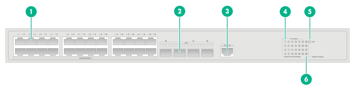
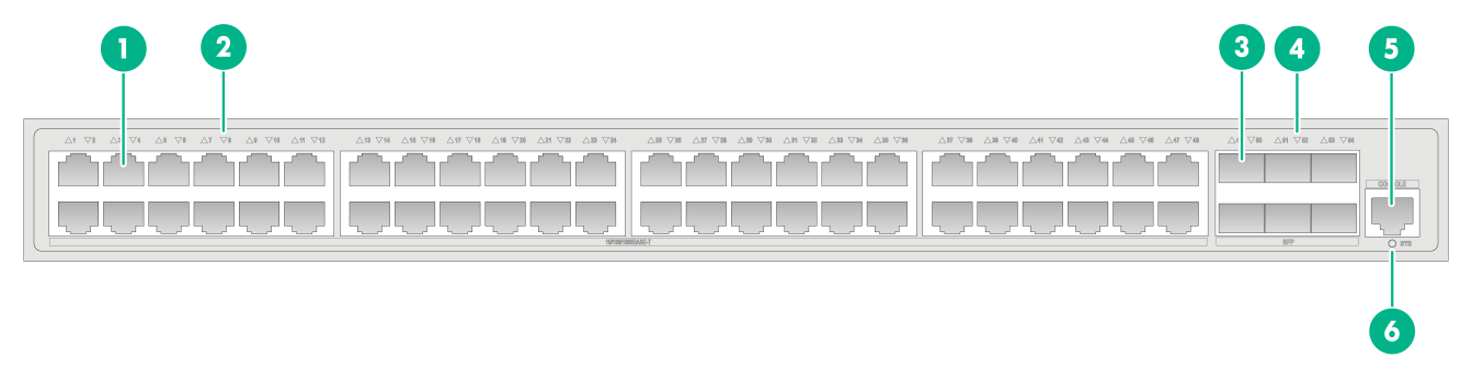
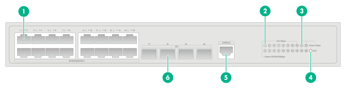
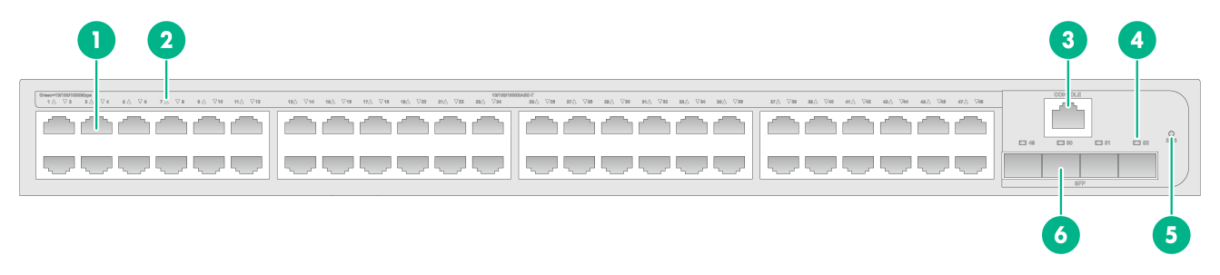
Figure 1 S5120V3-28S-EI front panel
|
(1) 10/100/1000BASE-T autosensing Ethernet port |
|
|
(2) SFP+ port |
(3) Serial console port |
|
(4) 10/100/1000BASE-T autosensing Ethernet port LED |
(5) System status LED |
|
(6) SFP+ port LED |
|
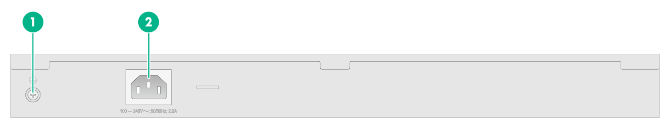
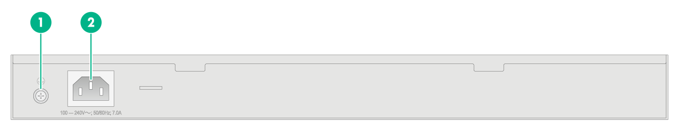
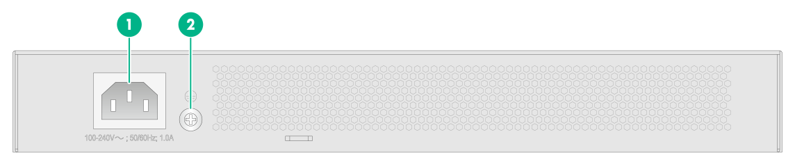
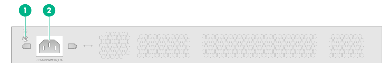
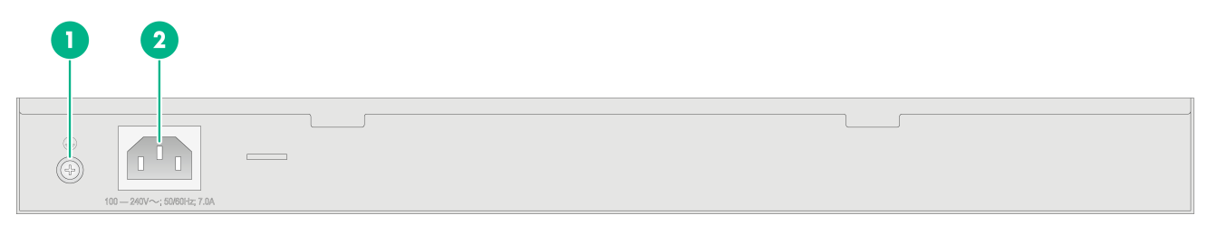
Figure 2 S5120V3-28S-EI rear panel

|
(1) Grounding screw |
(2) AC-input power receptacle |
S5120V3-54S-EI
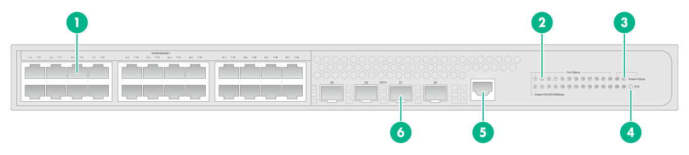
Figure 3 S5120V3-54S-EI front panel

|
(1) 10/100/1000BASE-T autosensing Ethernet port |
|
|
(2) 10/100/1000BASE-T autosensing Ethernet port LED |
|
|
(3) SFP+ port |
(4) SFP+ port LED |
|
(5) Serial console port |
(6) System status LED |
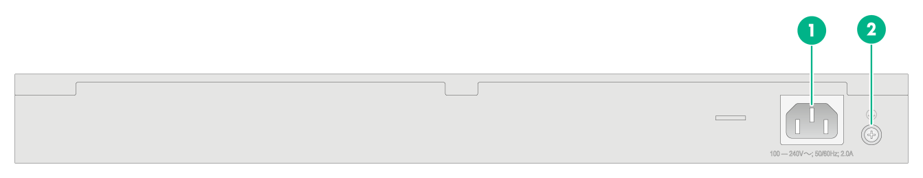
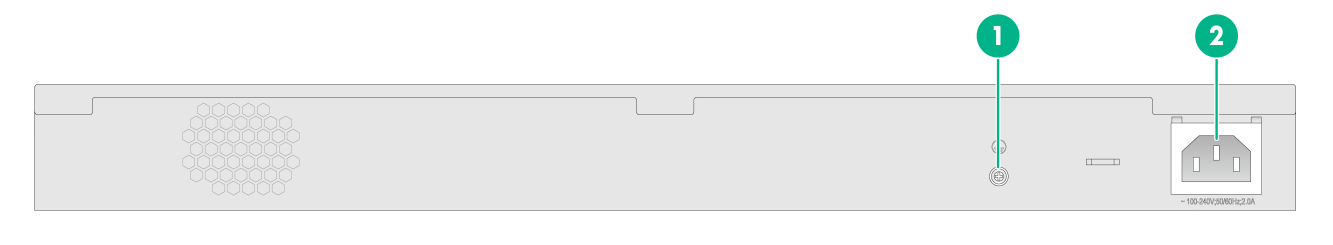
Figure 4 S5120V3-54S-EI rear panel

|
(1) AC-input power receptacle |
(2) Grounding screw |
S5120V3-28P-EI
Figure 5 S5120V3-28P-EI front panel

|
(1) 10/100/1000BASE-T autosensing Ethernet port |
|
|
(2) SFP port |
(3) Serial console port |
|
(4) 10/100/1000BASE-T autosensing Ethernet port LED |
|
|
(5) System status LED |
(6) SFP port LED |
Figure 6 S5120V3-28P-EI rear panel
|
(1) Grounding screw |
(2) AC-input power receptacle |
S5120V3-54P-EI
Figure 7 S5120V3-54P-EI front panel
|
(1) 10/100/1000BASE-T autosensing Ethernet port |
|||
|
(2) 10/100/1000BASE-T autosensing Ethernet port LED |
|||
|
(3) SFP port |
(4) SFP port LED |
|
|
|
(5) Serial console port |
(6) System status LED |
||
Figure 8 S5120V3-54P-EI rear panel
|
(1) AC-input power receptacle |
(2) Grounding screw |
S5120V3-36F-EI
Figure 9 S5120V3-36F-EI front panel
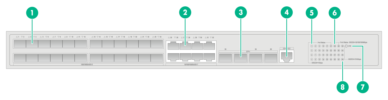
|
(1) SFP port |
(2) 10/100/1000BASE-T autosensing Ethernet port |
|
(3) SFP+ port |
(4) Serial console port |
|
(5) SFP port LED |
(6) 10/100/1000BASE-T autosensing Ethernet port LED |
|
(7) System status LED |
(8) SFP+ port LED |
Figure 10 S5120V3-36F-EI rear panel

|
(1) AC-input power receptacle |
(2) Grounding screw |
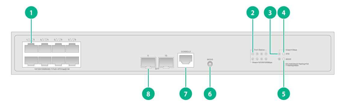
S5120V3-28S-HPWR-EI
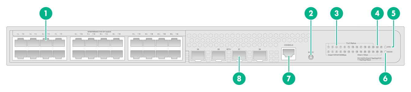
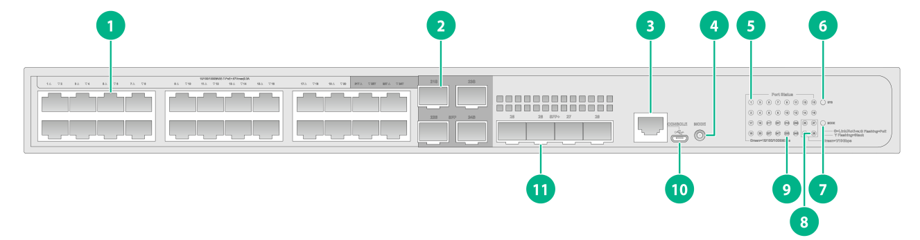
Figure 11 S5120V3-28S-HPWR-EI front panel

|
(1) 10/100/1000BASE-T autosensing Ethernet port |
|
|
(2) SFP+ port |
(3) Serial console port |
|
(4) 10/100/1000BASE-T autosensing Ethernet port LED |
|
|
(5) System status LED |
(6) Mode LED (MODE) |
|
(7) SFP+ port LED |
(8) Port LED mode switching button |
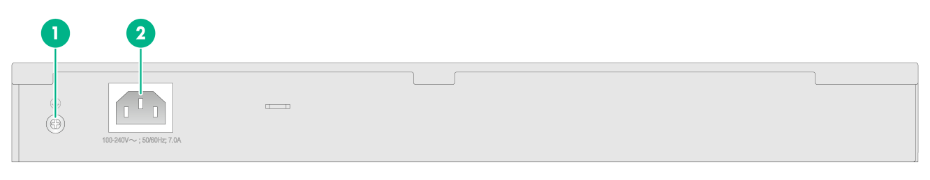
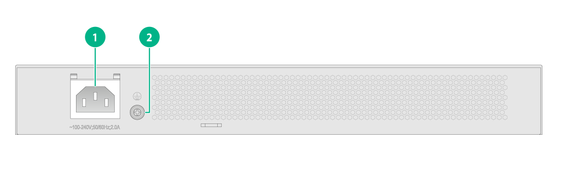
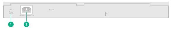
Figure 12 S5120V3-28S-HPWR-EI rear panel
|
(1) Grounding screw |
(2) AC-input power receptacle |
S5120V3-54S-PWR-EI
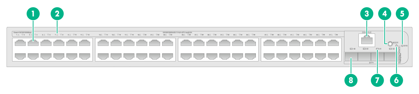
Figure 13 S5120V3-54S-PWR-EI front panel

|
(1) 10/100/1000BASE-T PoE+ autosensing Ethernet port |
|
|
(2) 10/100/1000BASE-T PoE+ autosensing Ethernet port LED |
|
|
(3) SFP+ port |
(4) SFP+ port LED |
|
(5) Serial console port |
(6) Port LED mode switching button |
|
(7) System status LED |
(8) Mode LED (MODE) |
Figure 14 S5120V3-54S-PWR-EI rear panel

|
(1) Grounding screw |
(2) AC-input power receptacle |
S5120V3-30MS-UPWR-DP-EI
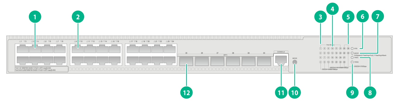
Figure 15 S5120V3-30MS-UPWR-DP-EI front panel
|
(1) 1000/100BASE-T autosensing Ethernet port |
|
|
(2) 2.5G/1000/100BASE-T autosensing Ethernet port |
|
|
(3) 1000/100BASE-T autosensing Ethernet port LED |
|
|
(4) 2.5G/1000/100BASE-T autosensing Ethernet port LED |
|
|
(5) SFP+ port LED |
(6) System status LED |
|
(7) Mode LED (MODE) |
(8) Power supply 1 status LED |
|
(9) Power supply 2 status LED |
(10) Port LED mode switching button |
|
(11) Serial console port |
(12) SFP+ port |
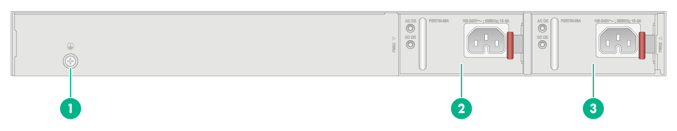
Figure 16 S5120V3-30MS-UPWR-DP-EI rear panel
|
(1) Grounding screw |
(2) Power supply 1 |
|
(3) Power supply 2 |
|
The S5120V3-30MS-UPWR-DP-EI switch has two power supply slots on the rear panel. It came with power supply slot 1 empty and power supply slot 2 installed with a filler panel. You can install one or two power supplies for the switch. In Figure 16, two PSR720-56A AC power supplies are installed on the switch.
S5120V3-LI switch series
S5120V3-10P-LI
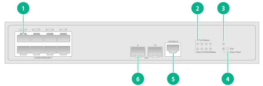
Figure 17 S5120V3-10P-LI front panel

|
(1) 10/100/1000BASE-T autosensing Ethernet port |
|
|
(2) 10/100/1000BASE-T autosensing Ethernet port LED |
|
|
(3) SFP port LED |
(4) System status LED (SYS) |
|
(5) Console port |
(6) SFP port |
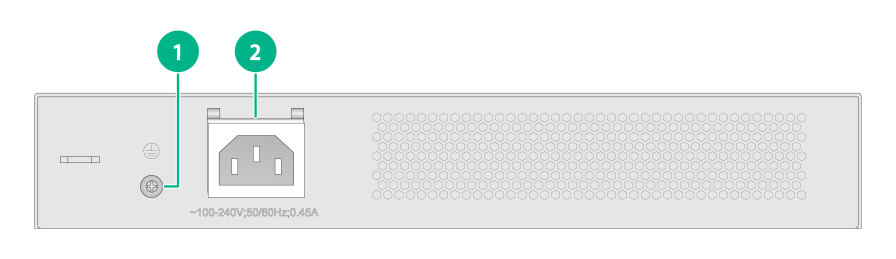
Figure 18 S5120V3-10P-LI rear panel
|
(1) Grounding screw |
(2) AC-input power receptacle |
S5120V3-20P-LI
Figure 19 S5120V3-20P-LI front panel
|
(1) 10/100/1000BASE-T autosensing Ethernet port |
|
|
(2) 10/100/1000BASE-T autosensing Ethernet port LED |
|
|
(3) SFP port LED |
(4) System status LED (SYS) |
|
(5) Console port |
(6) SFP port |
Figure 20 S5120V3-20P-LI rear panel
|
(1) AC-input power receptacle |
(2) Grounding screw |
S5120V3-28P-LI
Figure 21 S5120V3-28P-LI front panel

|
(1) 10/100/1000BASE-T autosensing Ethernet port |
|
|
(2) 10/100/1000BASE-T autosensing Ethernet port LED |
|
|
(3) SFP port LED |
(4) System status LED (SYS) |
|
(5) Console port |
(6) SFP port |
Figure 22 S5120V3-28P-LI rear panel

|
(1) Grounding screw |
(2) AC-input power receptacle |
S5120V3-28S-LI
Figure 23 S5120V3-28S-LI front panel
|
(1) 10/100/1000BASE-T autosensing Ethernet port |
|
|
(2) 10/100/1000BASE-T autosensing Ethernet port LED |
|
|
(3) SFP+ port LED |
(4) System status LED (SYS) |
|
(5) Console port |
(6) SFP+ port |
Figure 24 S5120V3-28S-LI rear panel

|
(1) Grounding screw |
(2) AC-input power receptacle |
S5120V3-52P-LI
Figure 25 S5120V3-52P-LI front panel

|
(1) 10/100/1000BASE-T autosensing Ethernet port |
|
|
(2) 10/100/1000BASE-T autosensing Ethernet port LED |
|
|
(3) Console port |
(4) SFP port LED |
|
(5) System status LED (SYS) |
(6) SFP port |
Figure 26 S5120V3-52P-LI rear panel

|
(1) Grounding screw |
(2) AC-input power receptacle |
S5120V3-52S-LI
Figure 27 S5120V3-52S-LI front panel

|
(1) 10/100/1000BASE-T autosensing Ethernet port |
|
|
(2) 10/100/1000BASE-T autosensing Ethernet port LED |
|
|
(3) Console port |
(4) SFP+ port LED |
|
(5) System status LED (SYS) |
(6) SFP+ port |
Figure 28 S5120V3-52S-LI rear panel
|
(1) Grounding screw |
(2) AC-input power receptacle |
S5120V3-28P-PWR-LI
Figure 29 S5120V3-28P-PWR-LI front panel

|
(1) 10/100/1000BASE-T autosensing Ethernet port |
(2) Port LED mode switching button |
|
(3) 10/100/1000BASE-T autosensing Ethernet port LED |
(4) SFP port LED |
|
(5) System status LED (SYS) |
(6) Mode LED (MODE) |
|
(7) Console port |
(8) SFP port |
Figure 30 S5120V3-28P-PWR-LI rear panel

|
(1) Grounding screw |
(2) AC-input power receptacle |
S5120V3-28S-PWR-LI
Figure 31 S5120V3-28S-PWR-LI front panel
|
(1) 10/100/1000BASE-T autosensing Ethernet port |
(2) Port LED mode switching button |
|
(3) 10/100/1000BASE-T autosensing Ethernet port LED |
(4) SFP+ port LED |
|
(5) System status LED (SYS) |
(6) Mode LED (MODE) |
|
(7) Console port |
(8) SFP+ port |
Figure 32 S5120V3-28S-PWR-LI rear panel
|
(1) Grounding screw |
(2) AC-input power receptacle |
S5120V3-52P-PWR-LI
Figure 33 S5120V3-52P-PWR-LI front panel

|
(1) 10/100/1000BASE-T autosensing Ethernet port |
|
|
(2) 10/100/1000BASE-T autosensing Ethernet port LED |
|
|
(3) Console port |
(4) Port LED mode switching button |
|
(5) System status LED (SYS) |
(6) Mode LED (MODE) |
|
(7) SFP port LED |
(8) SFP port |
Figure 34 S5120V3-52P-PWR-LI rear panel
|
(1) Grounding screw |
(2) AC-input power receptacle |
S5120V3-52S-PWR-LI
Figure 35 S5120V3-52S-PWR-LI front panel
|
(1) 10/100/1000BASE-T autosensing Ethernet port |
|
|
(2) 10/100/1000BASE-T autosensing Ethernet port LED |
|
|
(3) Console port |
(4) Port LED mode switching button |
|
(5) System status LED (SYS) |
(6) Mode LED (MODE) |
|
(7) SFP+ port LED |
(8) SFP+ port |
Figure 36 S5120V3-52S-PWR-LI rear panel

|
(1) Grounding screw |
(2) AC-input power receptacle |
S5120V3-10P-PWR-LI
Figure 37 S5120V3-10P-PWR-LI front panel
|
(1) 10/100/1000BASE-T autosensing Ethernet port |
|
|
(2) 10/100/1000BASE-T autosensing Ethernet port LED |
|
|
(3) SFP port LED |
(4) System status LED (SYS) |
|
(5) Mode LED (MODE) |
(6) Port LED mode switching button |
|
(7) Console port |
(8) SFP port |
Figure 38 S5120V3-10P-PWR-LI rear panel
|
(1) AC-input power receptacle |
(2) Grounding screw |
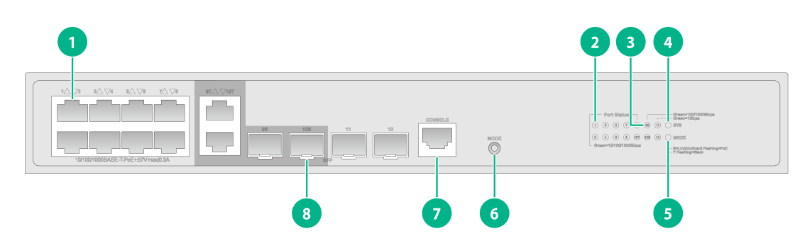
S5120V3-12TP-HPWR-LI
Figure 39 S5120V3-12TP-HPWR-LI front panel
|
(1) 10/100/1000BASE-T autosensing Ethernet port |
|
|
(2) 10/100/1000BASE-T autosensing Ethernet port LED |
|
|
(3) SFP port LED |
(4) System status LED (SYS) |
|
(5) Mode LED (MODE) |
(6) Port LED mode switching button |
|
(7) Console port |
(8) SFP port |
Figure 40 S5120V3-12TP-HPWR-LI rear panel

|
(1) AC-input power receptacle |
(2) Grounding screw |
S5120V3-28P-HPWR-LI
Figure 41 S5120V3-28P-HPWR-LI front panel
|
(1) 10/100/1000BASE-T autosensing Ethernet port |
||
|
(2) Console port |
(3) Port LED mode switching button |
|
|
(4) 10/100/1000BASE-T autosensing Ethernet port LED |
||
|
(5) System status LED (SYS) |
(6) Mode LED (MODE) |
|
|
(7) SFP port LED |
(8) SFP port |
|
Figure 42 S5120V3-28P-HPWR-LI rear panel

|
(1) Grounding screw |
(2) AC-input power receptacle |
S5120V3-28S-HPWR-LI
Figure 43 S5120V3-28S-HPWR-LI front panel
|
(1) 10/100/1000BASE-T autosensing Ethernet port |
(2) SFP port |
|
(3) Console port |
(4) Port LED mode switching button |
|
(5) 10/100/1000BASE-T autosensing Ethernet port LED |
|
|
(6) System status LED (SYS) |
(7) Mode LED (MODE) |
|
(8) SFP+ port LED |
(9) SFP port LED |
|
(10) Micro USB console port |
(11) SFP+ port |
Figure 44 S5120V3-28S-HPWR-LI rear panel
|
(1) Grounding screw |
(2) AC-input power receptacle |
S5120V3-28P-HPWR-LI-Q
Figure 45 S5120V3-28P-HPWR-LI-Q front panel
|
(1) 10/100/1000BASE-T autosensing Ethernet port |
(2) Port LED mode switching button |
|
(3) 10/100/1000BASE-T autosensing Ethernet port LED |
(4) SFP port LED |
|
(5) System status LED (SYS) |
(6) Mode LED (MODE) |
|
(7) Micro USB console port |
(8) Serial console port |
|
(9) SFP port |
|
Figure 46 S5120V3-28P-HPWR-LI-Q rear panel
|
(1) Grounding screw |
(2) AC-input power receptacle |
S5120V3-SI switch series
S5120V3-10P-SI
Figure 47 S5120V3-10P-SI front panel
|
(1) 10/100/1000BASE-T autosensing Ethernet port |
||
|
(2) 10/100/1000BASE-T autosensing Ethernet port LED |
||
|
(3) SFP port LED |
(4) System status LED (SYS) |
|
|
(5) Console port |
(6) SFP port |
|
Figure 48 S5120V3-10P-SI rear panel

|
(1) Grounding screw |
(2) AC-input power receptacle |
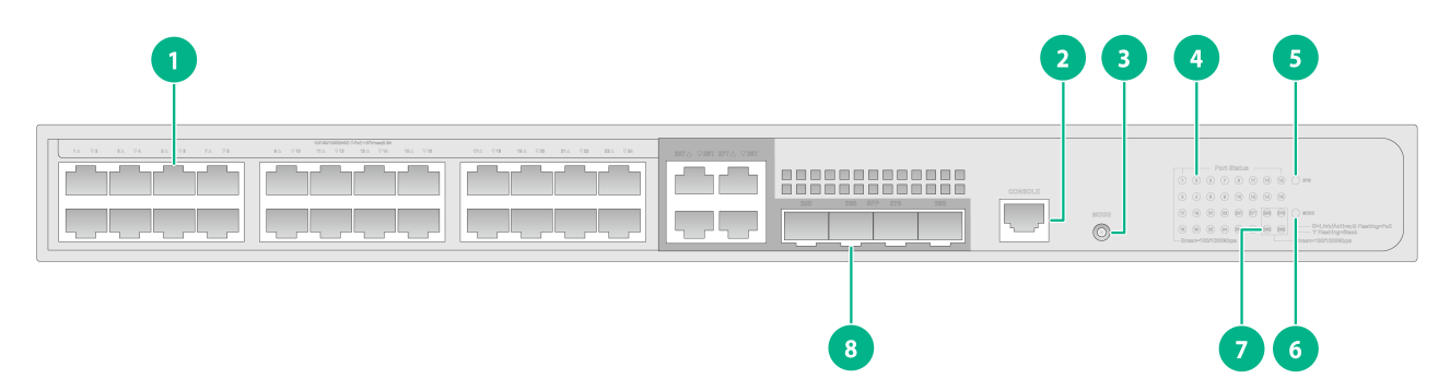
S5120V3-28P-SI
Figure 49 S5120V3-28P-SI front panel

|
(1) 10/100/1000BASE-T autosensing Ethernet port |
|
|
(2) 10/100/1000BASE-T autosensing Ethernet port LED |
|
|
(3) SFP port LED |
(4) System status LED (SYS) |
|
(5) Console port |
(6) SFP port |
Figure 50 S5120V3-28P-SI rear panel

|
(1) Grounding screw |
(2) AC-input power receptacle |
S5120V3-28S-SI
Figure 51 S5120V3-28S-SI front panel

|
(1) 10/100/1000BASE-T autosensing Ethernet port |
|
|
(2) 10/100/1000BASE-T autosensing Ethernet port LED |
|
|
(3) SFP+ port LED |
(4) System status LED (SYS) |
|
(5) Console port |
(6) SFP+ port |
Figure 52 S5120V3-28S-SI rear panel
|
(1) Grounding screw |
(2) AC-input power receptacle |
S5120V3-52P-SI
Figure 53 S5120V3-52P-SI front panel
|
(1) 10/100/1000BASE-T autosensing Ethernet port |
||
|
(2) 10/100/1000BASE-T autosensing Ethernet port LED |
||
|
(3) Console port |
(4) SFP port LED |
|
|
(5) System status LED (SYS) |
(6) SFP port |
|
Figure 54 S5120V3-52P-SI rear panel

|
(1) Grounding screw |
(2) AC-input power receptacle |
S5120V3-52S-SI
Figure 55 S5120V3-52S-SI front panel

|
(1) 10/100/1000BASE-T autosensing Ethernet port |
|
|
(2) 10/100/1000BASE-T autosensing Ethernet port LED |
|
|
(3) Console port |
(4) SFP+ port LED |
|
(5) System status LED (SYS) |
(6) SFP+ port |
Figure 56 S5120V3-52S-SI rear panel

|
(1) Grounding screw |
(2) AC-input power receptacle |
S5120V3-36F-SI
Figure 57 S5120V3-36F-SI front panel

|
(1) SFP port |
(2) 10/100/1000BASE-T autosensing Ethernet port |
|
(3) SFP+ port |
(4) Serial console port |
|
(5) SFP port LED |
(6) 10/100/1000BASE-T autosensing Ethernet port LED |
|
(7) System status LED |
(8) SFP+ port LED |
Figure 58 S5120V3-36F-SI rear panel

|
(1) AC-input power receptacle |
(2) Grounding screw |
S5120V3-28P-HPWR-SI
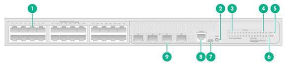
Figure 59 S5120V3-28P-HPWR-SI front panel
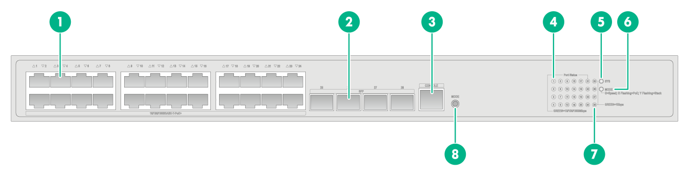
|
(1) 10/100/1000BASE-T-PoE+ autosensing Ethernet port |
|
|
(2) SFP port |
(3) Serial console port |
|
(4) 10/100/1000BASE-T PoE+ autosensing Ethernet port LED |
|
|
(5) System status LED |
(6) Mode LED (MODE) |
|
(7) SFP port LED |
(8) Port LED mode switching button |
Figure 60 S5120V3-28P-HPWR-SI rear panel

|
(1) Grounding screw |
(2) AC-input power receptacle |
S5120V3-28S-HPWR-SI-Q
Figure 61 S5120V3-28S-HPWR-SI-Q front panel

|
(1) 10/100/1000BASE-T autosensing Ethernet port |
(2) Port LED mode switching button |
|
(3) 10/100/1000BASE-T autosensing Ethernet port LED |
(4) SFP+ port LED |
|
(5) System status LED (SYS) |
(6) Mode LED (MODE) |
|
(7) Micro USB Console port |
(8) Serial console port |
|
(9) SFP+ port |
|
Figure 62 S5120V3-28S-HPWR-SI-Q rear panel
|
(1) Grounding screw |
(2) AC-input power receptacle |
S5120V3-54P-PWR-SI
Figure 63 S5120V3-54P-PWR-SI front panel
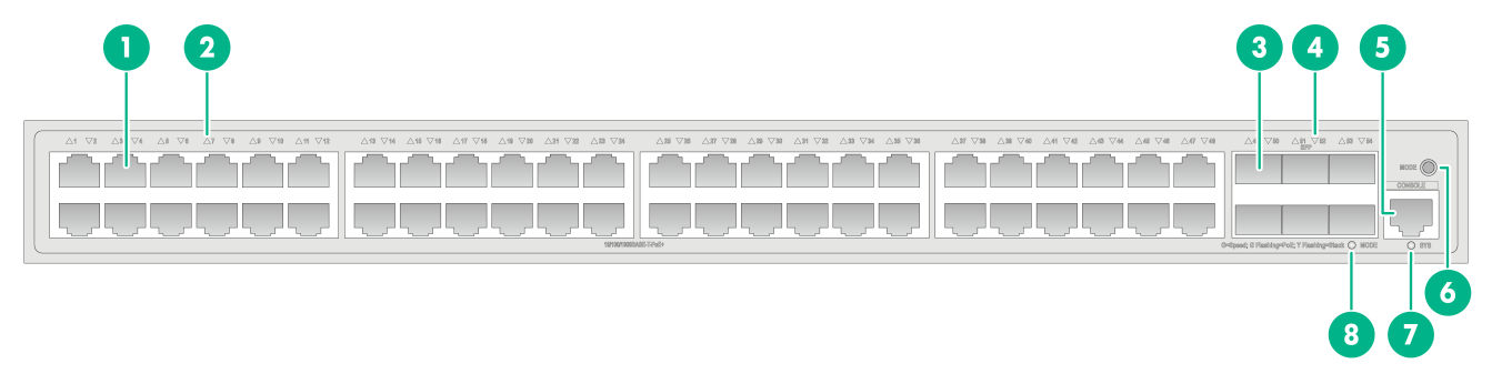
|
(1) 10/100/1000BASE-T-PoE+ autosensing Ethernet port |
|
|
(2) 10/100/1000BASE-T-PoE+ autosensing Ethernet port LED |
|
|
(3) SFP port |
(4) SFP port LED |
|
(5) Serial console port |
(6) Port LED mode switching button |
|
(7) System status LED |
(8) Mode LED (MODE) |
Figure 64 S5120V3-54P-PWR-SI rear panel
|
(1) Grounding screw |
(2) AC-input power receptacle |
Removable components
Removable components
The S5120V3-30MS-UPWR-DP-EI switch uses the modular design and supports the following removable components.
Table 10 Removable components
|
Removable component model |
S5120V3-30MS-UPWR-DP-EI |
|
Removable power supplies |
|
|
PSR360-56A |
Supported |
|
PSR720-56A |
Supported |
|
PSR1100-56A |
Supported |
|
PSR560-56D |
Supported |
You can install one power supply, or two power supplies for redundancy on the S5120V3-30MS-UPWR-DP-EI switch. Ensure uninterrupted power supply when only one power supply is present. The PoE power capacity of the switch varies by power supply configuration. For more information, see Table 4. The PoE capacity of the switch degrades when a power supply is faulty.
The removable components available for the S5120V3-30MS-UPWR-DP-EI switch are subject to change over time. For the most recent list of removable components for the switch, see the release notes.
|
|
NOTE: To view electronic label information of the S5120V3-30MS-UPWR-DP-EI switch, execute the display device manuinfo power command. |
Removable power supplies
Table 11 Removable power supplies
|
Power supply |
Specifications |
Reference |
|
PSR360-56A |
· Rated input voltage range: 100 VAC to 240 VAC @ 50 Hz or 60 Hz · Max input voltage range: 90 VAC to 264 VAC @ 47 Hz to 63 Hz · Max output power: 360 W |
H3C PSR360-56A Power Module User Manual |
|
PSR560-56D |
· Rated input voltage range: –48 VDC to –60 VDC · Max input voltage range: –36 VDC to –72 VDC · Max output power: 560 W |
H3C PSR560-56D Power Module User Manual |
|
PSR720-56A |
· Rated input voltage range: 100 VAC to 240 VAC @ 50 Hz or 60 Hz · Max input voltage range: 90 VAC to 264 VAC @ 47 Hz to 63 Hz · Max output power: 720 W |
H3C PSR720-56A Power Module User Manual |
|
PSR1110-56A |
· Rated input voltage range: 115 VAC to 240 VAC @ 50 Hz or 60 Hz · Max input voltage range: 102.5 VAC to 264 VAC @ 47 Hz to 63 Hz · Max output power: 1110 W |
H3C PSR1110-56A Power Module User Manual |
|
|
NOTE: A PSR1110-56A power supply including its handle adds 64 mm (2.52 in) to the total depth of the switch. |
Ports and LEDs
Ports
Console port
Table 12 Console port specifications
|
Item |
Serial console port |
Micro USB console port |
|
Connector type |
RJ-45 |
Micro USB Type B |
|
Compliant standard |
EIA/TIA-232 |
USB 2.0 |
|
Transmission baud rate |
9600 bps (default) to 115200 bps |
|
|
Services |
· Provides connection to an ASCII terminal. · Provides connection to the serial port of a local PC running terminal emulation program. |
· Provides connection to an ASCII terminal. · Provides connection to the USB port of a local PC running terminal emulation program. |
|
Switch models that provide a console port |
All switch models |
S5120V3-28P-HPWR-LI-Q S5120V3-28S-HPWR-SI-Q S5120V3-28S-HPWR-LI |
|
Restrictions and guidelines |
If you connect both the serial console port and micro USB console port, only the micro USB console port takes effect. |
|
10/100/1000BASE-T autosensing Ethernet port
Table 13 10/100/1000BASE-T autosensing Ethernet port specifications
|
Item |
Specification |
|
Connector type |
RJ-45 |
|
Port rate and duplex mode |
· 10/100 Mbps, half/full duplex · 1000 Mbps, full duplex |
|
Auto-MDI/MDI-X |
Supported |
|
Max transmission distance |
100 m (328.08 ft) |
|
Transmission medium |
Category-5 (or above) twisted pair cable |
|
Compatible standards |
IEEE 802.3i, 802.3u, 802.3ab |
|
Switch models that provide a 10/100/1000BASE-T autosensing Ethernet port |
All switch models (except the S5120V3-30MS-UPWR-DP-EI) |
2.5G/1000/100BASE-T autosensing Ethernet port
Table 14 2.5G/1000/100BASE-T autosensing Ethernet port specifications
|
Item |
Specification |
|
Connector type |
RJ-45 |
|
Speed, duplex mode, and MDIX mode |
· 1/2.5 Gbps, full duplex, auto-MDI/MDIX · 100 Mbps, full or half duplex, auto-MDI/MDIX |
|
Max transmission distance |
· 2.5 Gbps: 100 m (328.08 ft) · 1 Gbps: 140 m (459.32 ft) · 100 Mbps: 200 m (656.17 ft) NOTE: The maximum transmission distance between a PSE and PD depends on the peer device capacity and the twisted pair cable quality. |
|
Available cable |
Category-5e or above twisted pair cable |
|
Standards |
802.3u, IEEE 802.3ab, 802.3bz |
|
Switch model |
S5120V3-30MS-UPWR-DP-EI |
1000/100BASE-T Ethernet port
Table 15 1000/100BASE-T Ethernet port specifications
|
Item |
Specification |
|
Connector type |
RJ-45 |
|
Speed, duplex mode, and MDIX mode |
· 100 Mbps, half/full duplex · 1000 Mbps, full duplex · Auto-MDI/MDI-X |
|
Max transmission distance |
· 1 Gbps: 140 m (459.32 ft) · 100 Mbps: 200 m (656.17 ft) NOTE: The maximum transmission distance between a PSE and PD depends on the peer device capacity and the twisted pair cable quality. |
|
Transmission medium |
Category-5 (or above) twisted pair cable |
|
Standards |
IEEE 802.3i, 802.3u, 802.3ab |
|
Switch model |
S5120V3-30MS-UPWR-DP-EI |
SFP port
Table 16 SFP port specifications
|
Item |
Specification |
|
Available transceiver modules and cables |
· FE SFP transceiver modules and cables described in Table 17 (available only for the S5120V3-28P-EI, S5120V3-54P-EI, S5120V3-36F-EI, S5120V3-28P-HPWR-SI, S5120V3-54P-PWR-SI, and S5120V3-36F-SI switch models). · GE SFP transceiver modules and cables described in Table 18. |
|
Switch models |
· S5120V3-28P-EI, S5120V3-54P-EI, and S5120V3-36F-EI · S5120V3-10P-LI, S5120V3-20P-LI, S5120V3-28P-LI, S5120V3-52P-LI, S5120V3-28P-PWR-LI, S5120V3-52P-PWR-LI, S5120V3-10P-PWR-LI, S5120V3-12TP-HPWR-LI, S5120V3-28P-HPWR-LI, S5120V3-28S-HPWR-LI, and S5120V3-28P-HPWR-LI-Q · S5120V3-10P-SI, S5120V3-28P-SI, S5120V3-52P-SI, S5120V3-28P-HPWR-SI, S5120V3-54P-PWR-SI, and S5120V3-36F-SI |
|
Restrictions |
To use transceiver modules with a maximum transmission distance ≥ 80 km (49.71 miles) on an S5120V3-10P-LI, S5120V3-10P-PWR-LI, S5120V3-10P-SI, or S5120V3-12TP-HPWR-LI switch, make sure the ambient temperature is ≤ 40°C (104°F). |
Table 17 FE SFP transceiver modules
|
FE SFP transceiver module model |
Central wavelength |
Interface connector |
Interface cable |
Max transmission distance |
|
SFP-GE/FE-LX10-SM1310 |
1310 nm |
LC |
9/125 µm, SMF |
10 km (6.21 miles) |
|
SFP-FE-SX-MM1310-A |
1310 nm |
LC |
50/125 µm, MMF |
2 km (1.24 miles) |
|
62.5/125 µm, MMF |
||||
|
SFP-FE-LX-SM1310-A |
1310 nm |
LC |
9/125 µm, SMF |
15 km (9.32 miles) |
|
SFP-FE-LX-SM1310-D |
1310 nm |
LC |
9/125 µm, SMF |
15 km (9.32 miles) |
|
SFP-FE-LH40-SM1310 |
1310 nm |
LC |
9/125 µm, SMF |
40 km (24.86 miles) |
|
SFP-FE-LH80-SM1550 |
1550 nm |
LC |
9/125 µm, SMF |
80 km (49.71 miles) |
|
SFP-FE-LX-SM1310-BIDI |
TX: 1310 nm RX: 1550 nm |
LC |
9/125 µm, SMF |
15 km (9.32 miles) |
|
SFP-FE-LX-SM1550-BIDI |
TX: 1550 nm RX: 1310 nm |
|
|
IMPORTANT: The SFP-FE-LX-SM1310-BIDI and SFP-FE-LX-SM1550-BIDI transceiver modules must be used in pairs. For example, if one end uses the SFP-FE-LX-SM1310-BIDI transceiver module, the other end must use the SFP-FE-LX-SM1550-BIDI transceiver module. |
Table 18 GE SFP transceiver modules and cables
|
GE SFP transceiver module model and cable |
Central wavelength |
Interface connector |
Interface cable |
Modal bandwidth (MHz*km) |
Max transmission distance |
|
SFP transceiver modules |
|||||
|
SFP-GE-T |
N/A |
RJ-45 |
Twisted pair cable |
N/A |
100 m (328.08 ft) |
|
SFP-GE-T-D |
N/A |
RJ-45 |
Twisted pair cable |
N/A |
100 m (328.08 ft) |
|
SFP-GE-SX-MM850-A |
850 nm |
LC |
50/125 µm, MMF |
500 |
550 m (1804.46 ft) |
|
400 |
500 m (1640.42 ft) |
||||
|
62.5/125 µm, MMF |
200 |
275 m (902.23 ft) |
|||
|
160 |
200 m (656.17 ft) |
||||
|
SFP-GE-SX-MM850-D |
850 nm |
LC |
50/125 µm, MMF |
500 |
550 m (1804.46 ft) |
|
400 |
500 m (1640.42 ft) |
||||
|
62.5/125 µm, MMF |
200 |
275 m (902.23 ft) |
|||
|
160 |
200 m (656.17 ft) |
||||
|
SFP-GE-LX-SM1310-A |
1310 nm |
LC |
9/125 µm, SMF |
N/A |
10 km (6.21 miles) |
|
50/125 µm, MMF |
500/400 |
550 m (1804.46 ft) |
|||
|
62.5/125 µm, MMF |
500 |
550 m (1804.46 ft) |
|||
|
SFP-GE/FE-LX10-SM1310 |
1310 nm |
LC |
9/125 µm, SMF |
N/A |
10 km (6.21 miles) |
|
SFP-GE-LX-SM1310-D |
1310 nm |
LC |
9/125 µm, SMF |
N/A |
10 km (6.21 miles) |
|
SFP-GE-LH40-SM1310 |
1310 nm |
LC |
9/125 µm, SMF |
N/A |
40 km (24.86 miles) |
|
SFP-GE-LH40-SM1310-D |
1310 nm |
LC |
9/125 µm, SMF |
N/A |
40 km (24.86 miles) |
|
SFP-GE-LH40-SM1550 |
1550 nm |
LC |
9/125 µm, SMF |
N/A |
40 km (24.86 miles) |
|
SFP-GE-LH80-SM1550 |
1550 nm |
LC |
9/125 µm, SMF |
N/A |
80 km (49.71 miles) |
|
SFP-GE-LH80-SM1550-D |
1550 nm |
LC |
9/125 µm, SMF |
N/A |
80 km (49.71 miles) |
|
SFP-GE-LH100-SM1550 |
1550 nm |
LC |
9/125 µm, SMF |
N/A |
100 km (62.14 miles) |
|
SFP-GE-LX-SM1310-BIDI |
TX: 1310 nm RX: 1490 nm |
LC |
9/125 µm, SMF |
N/A |
10 km (6.21 miles) |
|
SFP-GE-LX-SM1490-BIDI |
TX: 149 nm RX: 1310 nm |
N/A |
|||
|
SFP-GE-LH40-SM1310-BIDI |
TX: 1310 nm RX: 550 nm |
LC |
9/125 µm, SMF |
N/A |
40 km (24.86 miles |
|
SFP-GE-LH40-SM1550-BIDI |
TX: 1550 nm RX: 1310 nm |
LC |
9/125 µm, SMF |
N/A |
40 km (24.86 miles |
|
SFP-GE-LH70-SM1490-BIDI |
TX: 1490 nm RX: 1550 nm |
LC |
9/125 µm, SMF |
N/A |
70 km (43.50 miles) |
|
SFP-GE-LH70-SM1550-BIDI |
TX: 1550 nm RX: 490 nm |
LC |
9/125 µm, SMF |
N/A |
70 km (43.50 miles) |
|
SFP cables |
|||||
|
SFP-STACK-Kit |
|
1.5 m (4.92 ft) |
|||
|
|
IMPORTANT: The SFP-GE-LX-SM1310-BIDI and SFP-GE-LX-SM1490-BIDI transceiver modules, the SFP-GE-LH40-SM1310-BIDI and SFP-GE-LH40-SM1550-BIDI transceiver modules, and the SFP-GE-LH70-SM1490-BIDI and SFP-GE-LH70-SM1550-BIDI transceiver modules must be used in pairs. For example, if one end uses the SFP-GE-LX-SM1310-BIDI transceiver module, the other end must use the SFP-GE-LX-SM1490-BIDI transceiver module. |
SFP+ port
Table 19 SFP+ port specifications
|
Item |
Specification |
|
Available transceiver modules and cables |
GE SFP transceiver modules and cables described in Table 18. 10-GE SFP transceiver modules and cables described in Table 20 |
|
Switch models |
· All S5120V3-EI switch models (except S5120V3-28P-EI and S5120V3-54P-EI) · S5120V3-28S-LI, S5120V3-52S-LI, S5120V3-28S-PWR-LI, S5120V3-52S-PWR-LI, and S5120V3-28S-HPWR-LI · S5120V3-28S-SI, S5120V3-52S-SI, S5120V3-28S-HPWR-SI-Q, and S5120V3-36F-SI |
|
Restrictions |
You can use only a maximum of two 10-GE transceiver modules with a maximum transmission distance of 80 km (49.71 miles) for the S5120V3-EI switch models (except the S5120V3-28P-EI and S5120V3-54P-EI) and the S5120V3-36F-SI switch. |
Table 20 10-GE SFP+ transceiver modules and cables
|
SFP+ transceiver module/cable model |
Central wavelength |
Interface connector |
Interface cable |
Modal bandwidth (MHz*km) |
Max transmission distance |
|
SFP+ transceiver modules |
|||||
|
SFP-XG-SX-MM850-A |
850 nm |
LC |
50/125 µm, MMF |
2000 |
300 m (984.25 ft) |
|
500 |
82 m (269.03 ft) |
||||
|
400 |
66 m (216.54 ft) |
||||
|
62.5/125 µm, MMF |
200 |
33 m (108.27 ft) |
|||
|
160 |
26 m (85.30 ft) |
||||
|
SFP-XG-SX-MM850-D |
850 nm |
LC |
50/125 µm, MMF |
2000 |
300 m (984.25 ft) |
|
500 |
82 m (269.03 ft) |
||||
|
400 |
66 m (216.54 ft) |
||||
|
62.5/125 µm, MMF |
200 |
33 m (108.27 ft) |
|||
|
160 |
26 m (85.30 ft) |
||||
|
SFP-XG-LX-SM1310 |
1310 nm |
LC |
9/125 µm, SMF |
N/A |
10 km (6.21 miles) |
|
SFP-XG-LX-SM1310-D |
1310 nm |
LC |
9/125 µm, SMF |
N/A |
10 km (6.21 miles) |
|
SFP-XG-LH40-SM1550 |
1550 nm |
LC |
9/125 µm, SMF |
N/A |
40 km (24.86 miles) |
|
SFP-XG-LH40-SM1550-D |
1550 nm |
LC |
9/125 µm, SMF |
N/A |
40 km (24.86 miles) |
|
SFP-XG-LH80-SM1550 |
1550 nm |
LC |
9/125 µm, SMF |
N/A |
80 km (49.71 miles) |
|
SFP-XG-LH80-SM1550-D |
1550 nm |
LC |
9/125 µm, SMF |
N/A |
80 km (49.71 miles) |
|
SFP-XG-LX-SM1270-BIDI |
TX: 1270 nm RX: 330 nm |
LC |
9/125 µm, SMF |
N/A |
10 km (6.21 miles) |
|
SFP-XG-LX-SM1330-BIDI |
TX: 1330 nm RX: 1270 nm |
LC |
9/125 µm, SMF |
N/A |
10 km (6.21 miles) |
|
SFP-XG-LH40-SM1270-BIDI |
TX: 1270 nm RX: 1330 nm |
LC |
9/125 µm, SMF |
N/A |
40 km (24.86 miles) |
|
SFP-XG-LH40-SM1330-BIDI |
TX: 1330 nm RX: 1270 nm |
LC |
9/125 µm, SMF |
N/A |
40 km (24.86 miles) |
|
SFP-XG-LH80-SM1490-BIDI |
TX: 1490 nm RX: 1550 nm |
LC |
9/125 µm, SMF |
N/A |
80 km (49.71 miles) |
|
SFP-XG-LH80-SM1550-BIDI |
TX: 1550 nm RX: 1490 nm |
LC |
9/125 µm, SMF |
N/A |
80 km (49.71 miles) |
|
SFP+ AOC cables |
|||||
|
SFP-XG-D-AOC-7M |
7 m (22.97 ft) |
||||
|
SFP-XG-D-AOC-10M |
10 m (32.81 ft) |
||||
|
SFP-XG-D-AOC-20M |
20 m (65.62 ft) |
||||
|
SFP+ copper cables |
|||||
|
LSWM1STK |
0.65 m (2.13 ft) |
||||
|
LSWM2STK |
1.2 m (3.94 ft) |
||||
|
LSWM3STK |
3 m (9.84 ft) |
||||
|
|
IMPORTANT: The SFP-XG-LX-SM1270-BIDI and SFP-XG-LX-SM1330-BIDI transceiver modules, SFP-XG-LH40-SM1270-BIDI and SFP-XG-LH40-SM1330-BIDI transceiver modules, and SFP-XG-LH80-SM1490-BIDI and SFP-XG-LH80-SM1550-BIDI transceiver modules must be used in pairs. For example, if one end uses the SFP-XG-LX-SM1270-BIDI transceiver module, the other end must use the SFP-XG-LX-SM1330-BIDI transceiver module. |
Figure 65 SFP+ cable
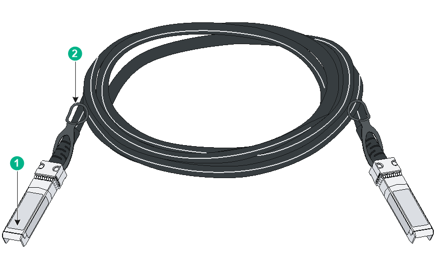
|
(1) Connector |
(2) Pull latch |
|
|
NOTE: · As a best practice, use H3C transceiver modules and cables for the switch. · The H3C transceiver modules and cables are subject to change over time. For the most recent list of H3C transceiver modules and cables, contact your H3C Support or marketing staff. · For more information about H3C transceiver modules and cables, see H3C Transceiver Modules User Guide. |
Combo interface
The S5120V3-28P-HPWR-LI and S5120V3-28S-HPWR-LI switches each provide four combo interfaces on the front panel. The S5120V3-12TP-HPWR-LI switch provides two combo interfaces on the front panel. A combo interface contains an SFP port and a 10/100/1000BASE-T autosensing Ethernet port. Only one of these two ports can operate at a time.
LEDs
System status LED
The system status LED shows the operating status of the switch.
Table 21 System status LED description
|
LED mark |
Status |
Description |
|
SYS |
Steady yellow |
Boot ROM booting stage. |
|
Steady green |
Linux kernel booting stage, or the switch has started up correctly. |
|
|
Flashing green (1 Hz) |
Software image loading and decompressing stage, or software booting stage. |
|
|
Steady red |
The switch has failed POST or the switch is faulty. |
|
|
Off |
The switch is powered off or has not started up correctly. |
Power supply status LED
Each removable power supply provides a status LED on the front panel to indicate its operating status.
Table 22 Power supply status LED description
|
LED mark |
Status |
Description |
|
PWR1/PWR1 |
Steady green |
A power supply is installed in the power supply slot, and the power supply is outputting power correctly. |
|
Steady yellow |
A power supply is installed in the power supply slot, but the power supply is faulty or no power is being supplied to the power supply. |
|
|
Off |
No power supply is installed in the power supply slot. |
Mode LED (MODE)
To show more information about the switch through the port status LEDs, some switch models provide a MODE LED to indicate the type of information that the port status LEDs are showing.
You can use the mode button to change the indication of the MODE LED.
· For the following switch models, the MODE LED changes in color and indication after you press the mode button and keep that state until you press the mode button again.
¡ S5120V3-10P-PWR-LI
¡ S5120V3-12TP-HPWR-LI
¡ S5120V3-28P-HPWR-LI
¡ S5120V3-28S-HPWR-LI
¡ S5120V3-28P-PWR-LI
¡ S5120V3-28S-PWR-LI
¡ S5120V3-52P-PWR-LI
¡ S5120V3-52S-PWR-LI
¡ S5120V3-28P-HPWR-LI-Q
¡ S5120V3-28S-HPWR-SI-Q
· For the following switch models, after you press the mode button for the mode LED to flash green, the mode LED keeps that state for only 60 seconds and then turns steady green automatically.
¡ S5120V3-28S-HPWR-EI
¡ S5120V3-54S-PWR-EI
¡ S5120V3-30MS-UPWR-DP-EI
¡ S5120V3-28P-HPWR-SI
¡ S5120V3-54P-PWR-SI
Table 23 Description for the MODE LED
|
LED mark |
Status |
Description |
|
MODE |
Steady green |
The port LEDs indicate port link status. |
|
Flashing green (available only for PoE models) |
The port status LEDs indicate the PoE power supply status of the ports. |
|
|
Flashing yellow |
· S5120V3-28P-HPWR-SI, S5120V3-54P-PWR-SI, S5120V3-28S-HPWR-EI, S5120V3-54S-PWR-EI, and S5120V3-30MS-UPWR-DP-EI—The port LEDs indicates the IRF member ID of the switch. For example, if the LEDs for ports 1 to 5 are steady green and the other LEDs are off, the IRF member ID of the switch is 5. · S5120V3-28P-PWR-LI, S5120V3-28S-PWR-LI, S5120V3-52P-PWR-LI, S5120V3-28S-HPWR-SI-Q, S5120V3-28P-HPWR-LI-Q, S5120V3-10P-PWR-LI, S5120V3-12TP-HPWR-LI, S5120V3-28P-HPWR-LI, S5120V3-28S-HPWR-LI, and S5120V3-52S-PWR-LI—The port LEDs indicates the IRF member ID of the switch. For example, if the LED for port 5 is steady green and the other LEDs are off, the IRF member ID of the switch is 5. |
10/100/1000BASE-T autosensing Ethernet port LED
For switch models that do not provide a port LED mode switching button, see Table 24 for the description for the 10/100/1000BASE-T autosensing Ethernet port LEDs.
Table 24 10/100/1000BASE-T autosensing Ethernet port LED description (1)
|
LED status |
Description |
|
Steady green |
A link is present on the port. |
|
Flashing green |
The port is sending or receiving data. |
|
Off |
No link is present on the port |
For switch models that provide a port LED mode switching button, the 10/100/1000BASE-T autosensing Ethernet port LEDs and the mode LED work in conjunction to indicate the operating status of the 10/100/1000BASE-T autosensing Ethernet ports.
Table 25 10/100/1000BASE-T autosensing Ethernet port LED description (2)
|
Mode LED status |
10/100/1000BASE-T autosensing Ethernet port LED status |
Description |
|
Steady green (link/active mode) |
Steady green |
A link is present on the port. |
|
Flashing green |
The port is sending or receiving data. |
|
|
Off |
No link is present on the port. |
|
|
Flashing green (PoE mode, available only for PoE models) |
Steady green |
Normal PoE power supply. |
|
Flashing green (1 Hz) |
· The PD attached to the port requires power higher than the maximum PoE output power of the port. · PoE overvoltage, overcurrent, or short circuit has occurred. · The remaining power of the switch is not sufficient for the PoE output requirement of the port. |
|
|
Off |
No link is present on the port, or PoE is not enabled on the port. |
|
|
Flashing yellow (IRF mode) |
Steady green |
· S5120V3-28P-HPWR-SI, S5120V3-54P-PWR-SI, S5120V3-28S-HPWR-EI, and S5120V3-54S-PWR-EI—The port LEDs indicates the IRF member ID of the switch. For example, if the LEDs for ports 1 to 5 are steady green and the other LEDs are off, the IRF member ID of the switch is 5. · S5120V3-10P-PWR-LI, S5120V3-12TP-HPWR-LI, S5120V3-28P-HPWR-LI, S5120V3-28S-HPWR-LI, S5120V3-28P-PWR-LI, S5120V3-28S-PWR-LI, S5120V3-52P-PWR-LI, S5120V3-52S-PWR-LI, S5120V3-28P-HPWR-LI-Q, and S5120V3-28S-HPWR-SI-Q—The port LEDs indicates the IRF member ID of the switch. For example, if the LED for port 5 is steady green and the other LEDs are off, the IRF member ID of the switch is 5. |
2.5G/1000/100BASE-T autosensing Ethernet port LED
Table 26 2.5G/1000/100BASE-T autosensing Ethernet port LED description
|
Mode LED status |
2.5G/1000/100BASE-T autosensing Ethernet port LED status |
Description |
|
Steady green (link/active mode) |
Steady green |
A link is present on the port. |
|
Flashing green |
The port is sending or receiving data. |
|
|
Off |
No link is present on the port. |
|
|
Flashing green (PoE mode, available only for PoE models) |
Steady green |
Normal PoE power supply. |
|
Flashing green (1 Hz) |
· The device attached to the port requires power higher than the maximum PoE output power of the port. · PoE overvoltage, overcurrent, or short circuit has occurred. · The remaining power of the switch is not sufficient for the PoE output requirement of the port. |
|
|
Off |
No link is present on the port, or PoE is not enabled on the port. |
|
|
Flashing yellow (IRF mode) |
Off |
|
1000/100BASE-T autosensing Ethernet port LED
Table 27 1000/100BASE-T autosensing Ethernet port LED description
|
Mode LED status |
1000/100BASE-T autosensing Ethernet port LED status |
Description |
|
Steady green (link/active mode) |
Steady green |
A link is present on the port. |
|
Flashing green |
The port is sending or receiving data. |
|
|
Off |
No link is present on the port. |
|
|
Flashing green (PoE mode) |
Steady green |
Normal PoE power supply. |
|
Flashing green (1 Hz) |
· The device attached to the port requires power higher than the maximum PoE output power on the port. · PoE overvoltage, overcurrent, or short circuit has occurred. · The remaining power of the switch is not sufficient for the PoE output requirement of the port. |
|
|
Off |
No link is present on the port, or PoE is not enabled on the port. |
|
|
Flashing yellow (IRF mode) |
The port LEDs indicates the IRF member ID of the switch. For example, if the LEDs for ports 1 to 5 are steady green and the other LEDs are off, the IRF member ID of the switch is 5. |
|
SFP/SFP+ port LED
Table 28 SFP/SFP+ port LED description
|
Status |
Description |
|
Steady green |
A link is present on the port. |
|
Flashing green |
The port is sending or receiving data. |
|
Off |
· No link is present on the port. · The mode LED is operating in IRF mode (available only for switch models with a mode button) · The mode LED is operating in PoE mode (available only for PoE switch models) |
Power input and output status LEDs on the power supplies
The PSR360-56A, PSR560-56D, PSR720-56A, and PSR1110-56A power supplies each provide a power input status LED and power output statue LED to indicate the power input and output status. For more information about the LEDs, see the user guide for the power supply.
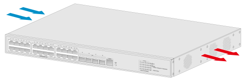
Cooling system
The switch uses a high-performance cooling system for fast heat dissipation and system stability. Consider the site ventilation design when you plan the installation site for the switch.
Table 29 Cooling system
|
Device model |
Fan tray type |
Airflow direction |
|
All S5120V3-EI switch models S5120V3-36F-SI S5120V3-28P-HPWR-SI S5120V3-54P-PWR-SI S5120V3-52P-PWR-LI S5120V3-52S-PWR-LI |
Fixed fan trays |
From the left side to the right side The S5120V3-28S-HPWR-EI switch is used as an example:
|
|
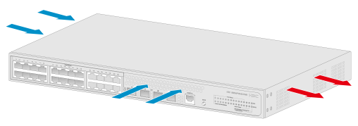
S5120V3-28P-PWR-LI S5120V3-28S-PWR-LI S5120V3-28P-HPWR-LI S5120V3-28S-HPWR-LI |
From the left and port sides to the right side The S5120V3-28S-HPWR-EI switch is used as an example:
|
|
|
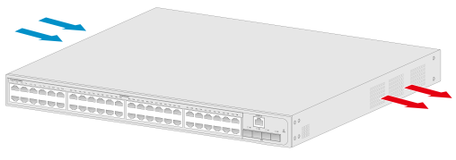
S5120V3-52P-LI S5120V3-52S-LI S5120V3-52P-SI S5120V3-52S-SI |
From the left and right sides to the power supply side The S5120V3-52P-LI switch is used as an example:
|
|
|
S5120V3-10P-LI S5120V3-10P-SI S5120V3-20P-LI S5120V3-28P-LI S5120V3-28S-LI S5120V3-28P-SI S5120V3-28S-SI S5120V3-10P-PWR-LI S5120V3-12TP-HPWR-LI S5120V3-28S-HPWR-SI-Q S5120V3-28P-HPWR-LI-Q |
Without fan trays |
Passive cooling |