- Table of Contents
-
- 10-MPLS Configuration Guide
- 00-Preface
- 01-Basic MPLS configuration
- 02-Static LSP configuration
- 03-LDP configuration
- 04-MPLS TE configuration
- 05-Static CRLSP configuration
- 06-RSVP configuration
- 07-Tunnel policy configuration
- 08-MPLS L3VPN configuration
- 09-IPv6 MPLS L3VPN configuration
- 10-MPLS L2VPN configuration
- 11-VPLS configuration
- 12-MPLS OAM configuration
- 13-MCE configuration
- Related Documents
-
| Title | Size | Download |
|---|---|---|
| 07-Tunnel policy configuration | 99.08 KB |
Tunnel policy application scenario
Restrictions and guidelines: Tunnel policy configuration
Configuring a tunnel binding policy
Configuring a preferred tunnel policy
Configuring a load sharing policy
Verifying and maintaining tunnel policies
Tunnel policy configuration examples
Example: Configuring exclusive tunnels
Example: Configuring tunnel bindings
Example: Configuring preferred tunnels and tunnel selection order
Configuring tunnel policies
About tunnel policies
Tunnel policies enable a PE to forward traffic for each MPLS VPN over a preferred tunnel or load share the traffic over multiple tunnels. Using tunnel policies can facilitate network planning and management and reduce processing overhead on PEs.
For more information about MPLS VPN, see "Configuring MPLS L3VPN."
Tunnel policy implementation
Tunnel binding
You can bind a destination IP address to one or more tunnels in a tunnel policy. After the tunnel policy is applied to a VPN, the VPN traffic to the destination IP address will be forwarded by the bound tunnels.
Preferred tunnel
You can specify a tunnel or tunnel bundle as a preferred tunnel in a tunnel policy. If the destination address of the preferred tunnel identifies a peer PE, the policy will forward traffic destined for that peer PE over the preferred tunnel.
If multiple preferred tunnels that have the same destination address are specified in a tunnel policy, the policy uses the following procedure to select a preferred tunnel:
1. The policy selects the first configured preferred tunnel.
2. If the first configured tunnel is not available, the policy selects the second tunnel, and so forth.
Since the policy uses only one tunnel, no load sharing will be performed on these tunnels. This method explicitly specifies a tunnel for an MPLS VPN, facilitating traffic planning. As a best practice, use this method.
Load sharing
You can configure tunnel load sharing by specifying the tunnel selection order and the number of tunnels for load sharing in a tunnel policy.
This method distributes traffic of a single VPN to multiple tunnels. The transmission delays on different tunnels can vary greatly. Therefore, the destination device or the upper layer application might take a great time to sequence the packets. As a best practice, do not use this method.
Tunnel selection rule
If you use all the tunnel binding, preferred tunnel, and load sharing methods to specify tunnels for a tunnel policy, the tunnel policy selects tunnels in the following steps:
· If the destination address of a bound tunnel identifies a peer PE, the tunnel policy uses the bound tunnel to forward the traffic to the peer PE.
For an SR-MPLS TE policy group, the tunnel destination address is the destination node address of the SR-MPLS TE policy group.
· If no bound tunnels are available for the peer PE, the tunnel policy selects a preferred tunnel whose destination address can identify the peer PE to forward traffic.
· If no preferred tunnel is available for a peer PE, the tunnel policy uses the load sharing method to forward the traffic to the peer PE.
Supported tunnel types
Tunnel policies support the following tunnel types:
· MPLS TE tunnels. For more information, see "Configuring MPLS TE."
· GRE tunnels. For more information about GRE, see Layer 3—IP Services Configuration Guide.
· MPLS LSPs. Only the load sharing method supports using MPLS LSPs.
· SR-MPLS TE policy group tunnels. For more information about SR-MPLS TE policies, see Segment Routing Configuration Guide.
Tunnel policy application scenario
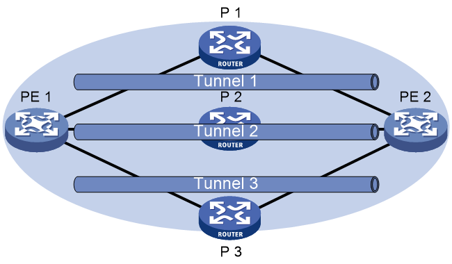
As shown in Figure 1, PE 1 and PE 2 have multiple tunnels in between and they are connected to multiple MPLS VPNs. You can control the paths for VPN traffic by using one of the following methods:
· Tunnel binding—Configure one tunnel policy, and bind different tunnels to different MPLS VPNs in the tunnel policy. Apply the tunnel policy to the MPLS VPNs to forward the traffic of each VPN over its bound tunnels.
· Preferred tunnel—Configure multiple tunnel policies, and specify a preferred tunnel for each policy. Apply these policies to different MPLS VPNs to forward the traffic of each VPN over a specific tunnel.
· Load sharing—Configure one tunnel policy, and specify the tunnel selection order and the number of tunnels for load sharing. Apply the tunnel policy to MPLS VPNs to forward the traffic of every VPN over multiple tunnels.
Figure 1 Tunnel policy application scenario
Restrictions and guidelines: Tunnel policy configuration
To configure a VPN to exclusively use a tunnel, perform the following operations:
1. Use the preferred-path command to specify the tunnel as the preferred tunnel in a tunnel policy.
2. Apply the policy only to that VPN.
Configuring a tunnel binding policy
1. Enter system view.
system-view
2. Enter the tunnel interface view of an MPLS TE tunnel.
interface tunnel number mode mpls-te
3. Reserve the MPLS TE tunnel for tunnel bindings in a tunnel policy.
mpls te reserved-for-binding
By default, an MPLS TE tunnel can be used by any tunnel policy implementation methods.
To bind an MPLS TE tunnel in a tunnel policy, you must execute this command for this tunnel.
To bind an SR-MPLS TE policy group in a tunnel policy, you do not need to execute this command.
4. Return to system view.
quit
5. Create a tunnel policy and enter tunnel policy view.
tunnel-policy tunnel-policy-name [ default ]
6. Bind tunnels to a destination IP address, so the tunnels can be used only for a specific VPN service.
binding-destination dest-ip-address { sr-policy group sr-policy-group-id | te { tunnel number }&<1-n> } [ ignore-destination-check ] [ down-switch ]
By default, a tunnel policy does not bind tunnels to a destination IP address.
You can bind tunnels to multiple destination IP addresses in a tunnel policy.
Configuring a preferred tunnel policy
1. Enter system view.
system-view
2. Create a tunnel policy and enter tunnel policy view.
tunnel-policy tunnel-policy-name [ default ]
3. Configure a tunnel or a tunnel bundle as a preferred tunnel.
preferred-path { tunnel number | tunnel-bundle number }
By default, no preferred tunnels are configured.
To enhance availability, you can associate multiple MPLS TE tunnels to a tunnel bundle, and specify the tunnel bundle as a preferred tunnel.
Configuring a load sharing policy
1. Enter system view.
system-view
2. Create a tunnel policy and enter tunnel policy view.
tunnel-policy tunnel-policy-name [ default ]
3. Configure the tunnel selection order and the number of tunnels for load sharing.
select-seq [ strict ] { cr-lsp | gre | lsp | sr-lsp | sr-policy } * load-balance-number number
By default, the policy selects only one tunnel in LSP, GRE, CRLSP, SRLSP, and SR-MPLS TE policy order.
Verifying and maintaining tunnel policies
To display tunnel information, execute the following command in any view:
display mpls tunnel { all | statistics | [ vpn-instance vpn-instance-name ] destination { ipv4-address | ipv6-address } }
Tunnel policy configuration examples
Example: Configuring exclusive tunnels
Network configuration
PE 1 has multiple tunnels to reach PE 2: two MPLS TE tunnels on interface Tunnel 1 and Tunnel 2, and one LDP LSP tunnel.
Two MPLS VPNs, vpna and vpnb, exist on PE 1. The VPN vpna exclusively uses the MPLS TE tunnel 1, and the VPN vpnb exclusively uses the MPLS TE tunnel 2.
Procedure
1. Configure tunnel policies on PE 1:
# Create tunnel policy preferredte1, and configure tunnel 1 as the preferred tunnel.
<PE1> system-view
[PE1] tunnel-policy preferredte1
[PE1-tunnel-policy-preferredte1] preferred-path tunnel 1
[PE1-tunnel-policy-preferredte1] quit
# Create tunnel policy preferredte2, and configure tunnel 2 as the preferred tunnel.
[PE1] tunnel-policy preferredte2
[PE1-tunnel-policy-preferredte2] preferred-path tunnel 2
[PE1-tunnel-policy-preferredte2] quit
2. Configure MPLS VPN instances and apply tunnel policies to the VPN instances:
# Create MPLS VPN instance vpna, and apply tunnel policy preferredte1 to it.
[PE1] ip vpn-instance vpna
[PE1-vpn-instance-vpna] route-distinguisher 100:1
[PE1-vpn-instance-vpna] vpn-target 100:1
[PE1-vpn-instance-vpna] tnl-policy preferredte1
[PE1-vpn-instance-vpna] quit
# Create MPLS VPN instance vpnb, and apply tunnel policy preferredte2 to it.
[PE1] ip vpn-instance vpnb
[PE1-vpn-instance-vpnb] route-distinguisher 100:2
[PE1-vpn-instance-vpnb] vpn-target 100:2
[PE1-vpn-instance-vpnb] tnl-policy preferredte2
Example: Configuring tunnel bindings
Network configuration
PE 1 has multiple tunnels to reach PE 2, including two MPLS TE tunnels. An MPLS VPN exists on PE 1. Configure a tunnel policy, so the two MPLS TE tunnels are only used to forward traffic for that VPN.
Procedure
1. Reserve the MPLS TE tunnels only for bound tunnels:
# Reserve MPLS TE tunnel 1 for tunnel bindings in a tunnel policy.
<PE1> system-view
[PE1] interface tunnel 1 mode mpls-te
[PE1-Tunnel1] mpls te reserved-for-binding
[PE1-Tunnel1] quit
# Reserve MPLS TE tunnel 2 for tunnel bindings in a tunnel policy.
[PE1] interface tunnel 2 mode mpls-te
[PE1-Tunnel2] mpls te reserved-for-binding
[PE1-Tunnel2] quit
2. Configure a tunnel policy on PE 1.
# Create a tunnel policy named text, bind the MPLS TE tunnels to the IP address of the MP-BGP peer, so that the tunnels can forward traffic only for a specific VPN service.
<PE1> system-view
[PE1] tunnel-policy text
[PE1-tunnel-policy-text] binding-destination 2.2.2.2 te tunnel 1 tunnel 2
[PE1-tunnel-policy-text] quit
3. Create MPLS VPN instance vpna, and apply tunnel policy text to it.
[PE1] ip vpn-instance vpna
[PE1-vpn-instance-vpna] route-distinguisher 100:1
[PE1-vpn-instance-vpna] vpn-target 100:1
[PE1-vpn-instance-vpna] tnl-policy text
[PE1-vpn-instance-vpna] quit
Example: Configuring preferred tunnels and tunnel selection order
Network configuration
PE 1 has multiple tunnels to reach PE 2: two MPLS TE tunnels on interfaces Tunnel 1 and Tunnel 2, and one LDP LSP tunnel.
PE 1 has multiple MPLS VPN instances: vpna, vpnb, vpnc, vpnd, and vpne. Table 1 shows the tunnel policy that PE 1 uses for each VPN instance.
Table 1 Tunnel policies used for VPN instances
|
VPN instance |
Tunnel policy |
|
vpna, vpnb |
Use MPLS TE tunnel Tunnel 1 as the preferred tunnel. |
|
vpnc, vpnd |
Use MPLS TE tunnel Tunnel 2 as the preferred tunnel. |
|
vpne |
Uses one tunnel selected in LDP LSP-MPLS TE order. |
Procedure
1. Configure tunnel policies on PE 1:
# Create tunnel policy preferredte1, and configure tunnel 1 as the preferred tunnel.
<PE1> system-view
[PE1] tunnel-policy preferredte1
[PE1-tunnel-policy-preferredte1] preferred-path tunnel 1
[PE1-tunnel-policy-preferredte1] quit
# Create tunnel policy preferredte2, and configure tunnel 2 as the preferred tunnel.
[PE1] tunnel-policy preferredte2
[PE1-tunnel-policy-preferredte2] preferred-path tunnel 2
[PE1-tunnel-policy-preferredte2] quit
# Create tunnel policy select-lsp.
[PE1] tunnel-policy select-lsp
# Configure the policy to select only one tunnel in LDP LSP-MPLS TE order.
[PE1-tunnel-policy-select-lsp] select-seq lsp cr-lsp load-balance-number 1
[PE1-tunnel-policy-select-lsp] quit
2. Configure MPLS VPN instances and apply tunnel policies to the VPN instances:
# Create MPLS VPN instances vpna and vpnb, and apply tunnel policy preferredte1 to them.
[PE1] ip vpn-instance vpna
[PE1-vpn-instance-vpna] route-distinguisher 100:1
[PE1-vpn-instance-vpna] vpn-target 100:1
[PE1-vpn-instance-vpna] tnl-policy preferredte1
[PE1-vpn-instance-vpna] quit
[PE1] ip vpn-instance vpnb
[PE1-vpn-instance-vpnb] route-distinguisher 100:2
[PE1-vpn-instance-vpnb] vpn-target 100:2
[PE1-vpn-instance-vpnb] tnl-policy preferredte1
[PE1-vpn-instance-vpnb] quit
# Create MPLS VPN instances vpnc and vpnd, and apply tunnel policy preferredte2 to them.
[PE1] ip vpn-instance vpnc
[PE1-vpn-instance-vpnc] route-distinguisher 100:3
[PE1-vpn-instance-vpnc] vpn-target 100:3
[PE1-vpn-instance-vpnc] tnl-policy preferredte2
[PE1-vpn-instance-vpnc] quit
[PE1] ip vpn-instance vpnd
[PE1-vpn-instance-vpnd] route-distinguisher 100:4
[PE1-vpn-instance-vpnd] vpn-target 100:4
[PE1-vpn-instance-vpnd] tnl-policy preferredte2
[PE1-vpn-instance-vpnd] quit
# Create MPLS VPN instance vpne, and apply tunnel policy select-lsp to it.
[PE1] ip vpn-instance vpne
[PE1-vpn-instance-vpne] route-distinguisher 100:5
[PE1-vpn-instance-vpne] vpn-target 100:5
[PE1-vpn-instance-vpne] tnl-policy select-lsp
