- Table of Contents
-
- 05-Layer 2—WAN Access Configuration Guide
- 00-Preface
- 01-PPP configuration
- 02-L2TP configuration
- 03-HDLC configuration
- 04-ISDN configuration
- 05-ATM configuration
- 06-Modem management configuration
- 07-Mobile communication modem management configuration
- 08-DDR configuration
- 09-Frame Relay configuration
- 10-IPoE configuration
- Related Documents
-
| Title | Size | Download |
|---|---|---|
| 10-IPoE configuration | 463.82 KB |
Contents
Restrictions: Licensing requirements for IPoE
Restrictions and guidelines: IPoE configuration
Enabling IPoE and setting the IPoE access mode
Configuring dynamic individual users
Dynamic individual user tasks at a glance
Enabling dynamic individual users
Configuring authentication user naming conventions for dynamic individual users
Configuring passwords for dynamic individual users
Configuring ISP domains for dynamic individual users
Configuring the maximum number of dynamic IPoE sessions
Configuring trusted DHCP options for DHCP users
Configuring trusted source IP addresses for unclassified-IP users
Configuring static individual users
Static individual user tasks at a glance
Enabling static individual users
Configuring static IPoE sessions
Configuring authentication user naming conventions for static individual users
Configuring passwords for static individual users
Configuring ISP domains for static individual users
Configuring the static IPoE whitelist feature
Configuring interface-leased users
Configuring subnet-leased users
Configuring ISP domains for leased users
Configuring service-specific ISP domains
About configuring service-specific ISP domains
Configuring service-specific ISP domains for IPv4 users
Configuring service-specific ISP domains for IPv6 users
Configuring the quiet timer for users
Configuring online detection for IPoE users
Configuring NAS-Port-Type for an interface
Setting the traffic statistics update timer for IPoE sessions
Configuring NAS-Port-ID formats
About configuring NAS-Port-ID formats
Configuring the NAS-Port-ID format for IPv4 users
Configuring the NAS-Port-ID format for IPv6 users
Display and maintenance commands for IPoE
Display and maintenance commands for IPv4 IPoE
Display and maintenance commands for IPv6 IPoE
Example: Configuring an unclassified-IP user
Example: Configuring a DHCP user
Example: Configuring an IPv6-ND-RS user
Example: Configuring subnet-leased users
Example: Configuring an interface-leased user
Example: Configuring a VPN DHCP user
Example: Configuring online detection
DHCP clients failed to come online
Inter-card traffic statistics failure on an aggregate interface
Configuring IPoE
About IPoE
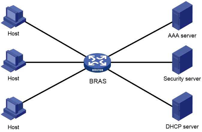
IP over Ethernet (IPoE) enables a BRAS to connect and authenticate users over IPoE connections.
As shown in Figure 1, a BRAS connects hosts over IPoE connections, and provides AAA, security, and DHCP services for the hosts. This solution does not require the hosts to install any client software.
Figure 1 IPoE network diagram
IPoE access modes
IPoE supports Layer 2 and Layer 3 access modes.
· Layer 2 access mode
Hosts directly access the BRAS. The hosts connect to the BRAS directly or through Layer 2 devices. The BRAS uses MAC addresses to identify the hosts.
· Layer 3 access mode
Hosts use routing to access the BRAS. The hosts connect to the BRAS directly or through Layer 3 devices. When a Layer 3 device resides between the hosts and the BRAS, the source MAC address of packets received by the BRAS is the MAC address of the Layer 3 device. Therefore, the BRAS uses IP addresses or VLAN IDs to identify hosts.
IPoE users
IPoE users include individual users and leased users.
Individual users
Individual users use independent IPoE services. The BRAS authenticates, authorizes, and bills individual users based on user location and packet information. Individual users include dynamic and static individual users.
· Dynamic individual users
IPoE defines the following dynamic individual users:
¡ DHCP user—Sends DHCP packets to trigger IPoE session establishment.
¡ IPv6-ND-RS user—Sends IPv6 ND RS packets to trigger IPoE session establishment.
¡ Unclassified-IP user—Sends packets other than DHCP and IPv6 ND RS packets to trigger IPoE session establishment.
· Static individual users
Static individual users trigger IPoE session establishment by sending IP packets. If an IP packet matches a manually configured IPoE session, the BRAS authenticates the user and establishes an IPoE session.
Leased users
Leased users include the following types:
· Interface-leased user—Represents hosts that rent the same interface.
· Subnet-leased user—Represents hosts that rent a subnet of an interface.
The BRAS automatically uses the credentials configured for a leased user to perform authentication. Users are not required to send IP packets to trigger authentication.
IPoE session
IPoE sessions include dynamic and static sessions.
Dynamic IPoE session
IPoE sessions established for dynamic individual users are dynamic IPoE sessions.
The BRAS disconnects a dynamic IPoE session in one of the following cases:
· The AAA-authorized service expires.
· The AAA server logs out the user.
· The user traffic is less than the authorized traffic during the idle-timeout time.
· The BRAS cannot detect the user after the number of detection attempts reaches the maximum.
· The IP address lease expires.
· The IPoE session is restarted.
· The access interface goes down.
Static IPoE session
IPoE sessions established for static individual users, interface-leased users, and subnet-leased users are static IPoE sessions.
The BRAS creates a static IPoE session based on configured information after you enable IPoE on an interface. The BRAS initiates user authentication based on the configured username and password upon receiving IP packets from static individual users. Static IPoE sessions can only be deleted manually at the CLI.
For static individual users, the BRAS creates a static IPoE session based on configured information after you enable IPoE on an interface. The BRAS initiates user authentication based on the configured username and password upon receiving IP packets from static individual users.
For interface-leased users and subnet-leased users, the BRAS creates a static IPoE session based on configured information after you enable IPoE on an interface. The BRAS initiates user authentication based on the configured username and password.
IPoE addressing
IPoE addressing varies with user types.
· DHCP users obtain IP addresses in the following sequence:
¡ Obtain IP addresses from the AAA-authorized IP address pool.
¡ Obtain IP addresses from the IP address pool configured in the ISP domain if the AAA server does not authorize any IP address pools.
¡ Obtain IP addresses in the same network segment as the interface IP address if no IP address pool is configured in the ISP domain.
· IPv6-ND-RS users obtain the AAA-authorized IPv6 prefix from IPoE, and generate an IPv6 address based on the prefix. If no AAA-authorized IPv6 prefix exists, the user adopts the first 64-bit IPv6 prefix of the interface to generate an IPv6 address.
· Other users adopt static IP addresses or obtain IP addresses from the DHCP server without using IPoE.
IPoE access procedure
IPoE access includes the following steps:
1. The BRAS initiates authentication.
The BRAS obtains information from user packets or IPoE sessions statically configured, and sends authentication requests.
2. The AAA server authenticates users.
The AAA server completes user authentication and sends the result to the BRAS. The security server, if configured, completes security authorization and sends the result to the BRAS.
3. (Optional.) DHCP allocates IP addresses.
The DHCP server assigns an IP address to a DHCP user and IPoE assigns an IPv6 prefix to an IPv6-ND-RS user.
4. The BRAS performs access control.
The BRAS permits the user to get online and performs access control and billing based on the authorized result.
Access procedure for DHCP users
This section uses a DHCPv4 user as an example to illustrate the access procedure for DHCP users. The BRAS operates as a DHCP relay.
Figure 2 Access procedure for a DHCPv4 user
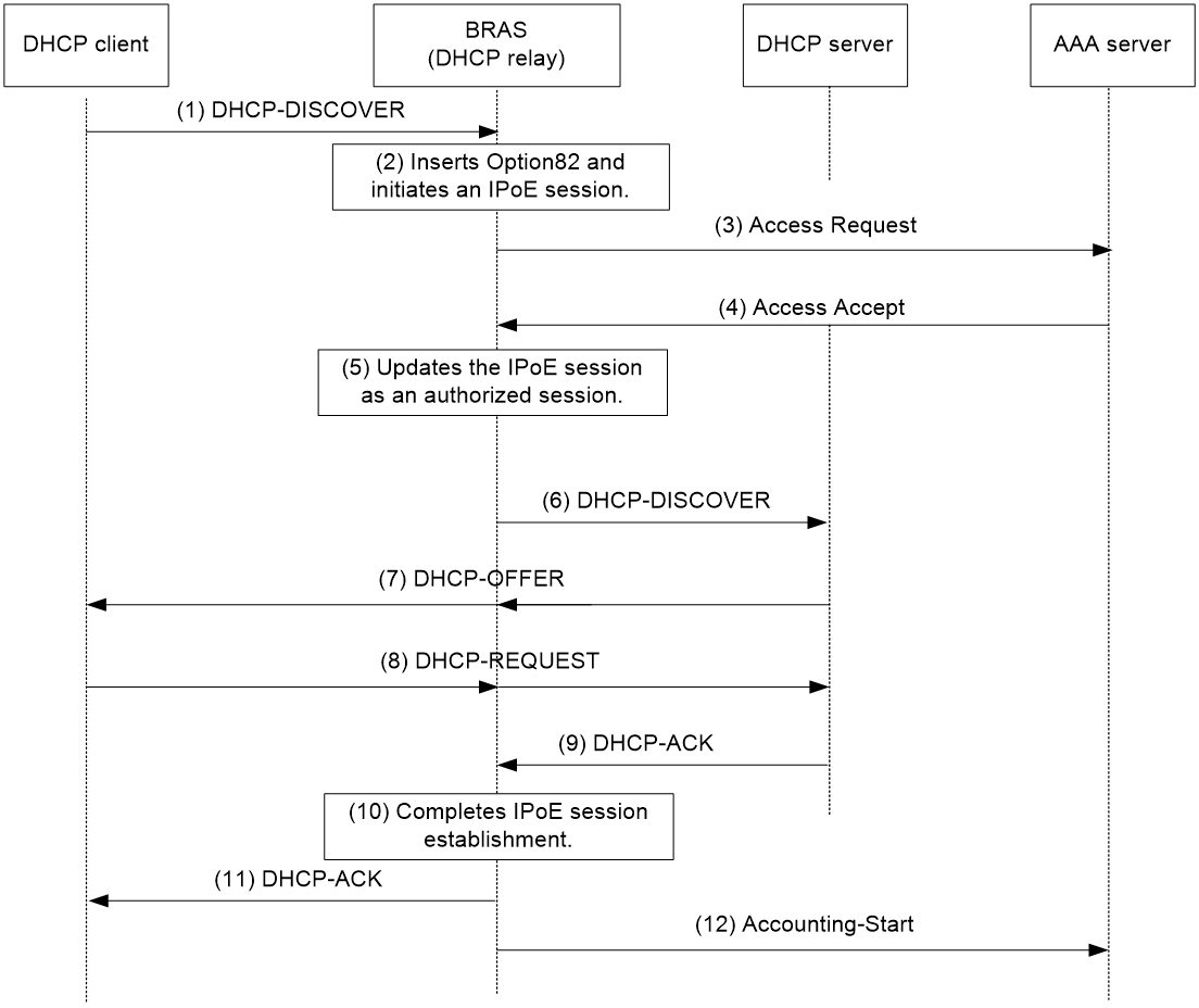
1. The DHCP client sends a DHCP-DISCOVER message to the BRAS.
2. The BRAS inserts Option 82 in the DHCP-DISCOVER message, and creates an IPoE session.
3. The BRAS sends the AAA server an access request that includes user information, such as the client ID and source MAC address.
4. The AAA server returns an access accept that contains authorization information to the BRAS if the authentication succeeds. If the authentication fails, the AAA server returns a reject message.
5. The BRAS marks the IPoE session state as success and forwards the DHCP-DISCOVER message to the DHCP server if the authentication succeeds. If the authentication fails, the BRAS marks the session as failure and discards the DHCP-DISCOVER message.
6. The DHCP server sends a DHCP-OFFER message to the BRAS.
7. The BRAS forwards the DHCP-OFFER message to the DHCP client.
8. The DHCP client sends a DHCP-REQUEST message to the BRAS.
9. The BRAS forwards the DHCP-REQUEST message to the specified DHCP sever.
10. The DHCP server sends a DHCP-ACK message containing the assigned IP address to the BRAS.
11. The BRAS performs the following:
a. Obtains address information from the DHCP-ACK message.
b. Assigns a user profile.
c. Updates the IPoE session information.
d. Forwards the DHCP-ACK message to the client.
e. Marks the session state as online.
If the authentication fails, the BRAS marks the session as failure and discards the DHCP-DISCOVER message.
12. The DHCP client obtains configuration information from the DHCP-ACK message.
13. The BRAS sends the AAA server a message to start accounting.
Access procedure for IPv6-ND-RS users
This example uses a Layer 2 device as the BRAS.
Figure 3 Access procedure for IPv6-ND-RS users

1. The host sends an IPv6 ND RS packet to the BRAS.
2. The BRAS initiates an IPoE session and sends the AAA server an access request that contains user information, such as the source MAC address.
3. The AAA server returns an access accept that contains authorization information to the BRAS if the authentication succeeds. If the authentication fails, the AAA server returns a reject message.
4. The BRAS performs the following:
a. Generates an IPv6 address based on the host's MAC address and the IPv6 prefix.
b. Updates the IPoE session information.
c. Marks the session as success.
If the authentication fails, the BRAS marks the session as failure and discards the IPv6 ND RS packet.
5. The BRAS assigns a user profile and sends the host an IPv6 ND RA packet containing the IPv6 prefix.
6. The host generates an IPv6 address based on the received IPv6 prefix.
7. The BRAS sends the AAA server a message to start the service accounting.
Access procedure for unclassified-IP users
Figure 4 Access procedure for unclassified-IP users
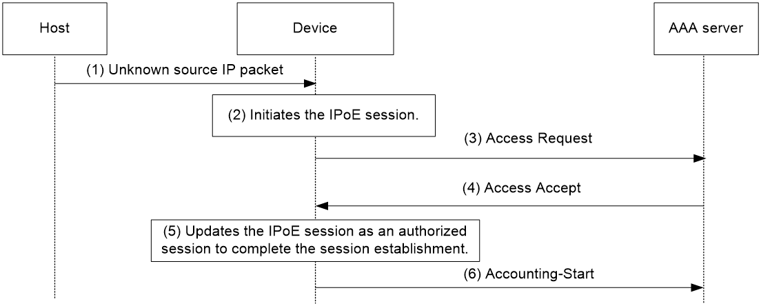
1. The host sends an IP packet to the BRAS.
2. The BRAS obtains user information from the IP packet, and matches the user information against existing IPoE sessions.
¡ If no match is found, the BRAS initiates an IPoE session for the user. (This section uses this case as an example.)
¡ If the information matches an authenticated session, the BRAS forwards the IP packet.
¡ If the information matches an unauthenticated session, the BRAS discards the IP packet.
3. The BRAS sends the AAA server an access request containing the obtained information, such as the source IP address or source MAC address.
4. The AAA server returns an access accept that contains authorization information if the authentication succeeds. If the authentication fails, the AAA server returns a reject message.
5. The BRAS assigns a user profile and marks the IPoE session state as online.
6. The BRAS sends the AAA server a message to start the service accounting.
Access procedure for static and leased users
The access procedure for static users is as follows:
1. The user statically configures an IPoE session at the CLI on the BRAS.
2. The user sends an IP packet to the BRAS.
3. The BRAS obtains user information from the IP packet, and sends the AAA server an access request containing configured IPoE session information.
4. The AAA server returns an access accept that contains authorization information if the authentication succeeds. If the authentication fails, the AAA server returns a reject message.
5. The BRAS assigns the user profile and marks the IPoE session state as online.
6. The host receives the user profile.
7. The BRAS sends the AAA server a message to start the service accounting.
The access procedure for leased users is as follows:
1. The user statically configures an IPoE session at the CLI on the BRAS.
2. The BRAS automatically obtains configured IPoE session information and sends the AAA server an access request.
3. The AAA server returns an access accept that contains authorization information if the authentication succeeds. If the authentication fails, the AAA server returns a reject message.
4. The BRAS assigns the user profile and marks the IPoE session state as online.
5. The host receives the user profile.
6. The BRAS sends the AAA server a message to start the service accounting.
Support for MPLS L3VPN
IPoE supports MPLS L3VPN. It uses AAA to authorize VPNs for users. Before you bind a VPN instance to an interface, you must delete existing IPoE sessions on the interface for the users to communicate in their authorized VPNs.
|
|
NOTE: Leased users do not support AAA-authorized VPNs through ISP domains or AAA servers. For more information about VPN authorization through ISP domains, see Security Configuration Guide. |
Support for ITA
ITA provides accounting and bandwidth solutions for users based on the destination addresses they access.
For more information about configuring ITA, see Security Configuration Guide.
Restrictions: Licensing requirements for IPoE
The maximum number of IPoE sessions varies by license and device model. For more information about licenses, see Fundamentals Configuration Guide.
Restrictions and guidelines: IPoE configuration
IPoE supports the following interfaces:
· Layer 3 aggregate interfaces.
· Layer 3 aggregate subinterfaces
· Layer 3 Ethernet interfaces.
· Layer 3 Ethernet subinterfaces.
· L3VE interfaces.
· L3VE subinterfaces.
· VEth interfaces.
· VEth subinterfaces.
· VLAN interfaces.
IPoE tasks at a glance
To configure IPoE, perform the following tasks:
1. Enabling IPoE and setting the IPoE access mode
2. Configure user types
¡ Configuring dynamic individual users
¡ Configuring static individual users
Individual users and leased users cannot be configured on the same interface. Dynamic and static individual users can be configured on the same interface.
3. (Optional.) Configuring service-specific ISP domains
4. (Optional.) Configuring the quiet timer for users
5. (Optional.) Configuring online detection for IPoE users
6. (Optional.) Configuring NAS-Port-Type for an interface
7. (Optional.) Setting the traffic statistics update timer for IPoE sessions
8. (Optional.) Enabling IPoE user logging
9. (Optional.) Configuring NAS-Port-ID formats
Prerequisites for IPoE
Complete the following configuration as required:
· Configure the DHCP server.
· Enable the DHCP relay agent on the BRAS.
· Configure the RADIUS server and client. For more information about how to configure a RADIUS client, see AAA configuration in Security Configuration Guide.
· Configure security policies on the H3C iMC security server and configure the security server's IP address on the BRAS. For more information about how to configure a security server, see AAA configuration in Security Configuration Guide.
· Configure local user accounts on the BRAS if local authentication is used. For more information about how to configure a local user account, see AAA configuration in Security Configuration Guide.
· Make sure the hosts, BRAS, and servers can reach each other.
Enabling IPoE and setting the IPoE access mode
Restrictions and guidelines
To change the IPoE access mode, disable IPoE, and then set the new IPoE mode when you enable IPoE.
Procedure
1. Enter system view.
system-view
2. Enter interface view.
interface interface-type interface-number
3. Enable IPoE and set the IPoE access mode on an IPv4 interface
ip subscriber { l2-connected | routed } enable
By default, IPv4 IPoE is disabled.
4. Enable IPoE and set the IPoE access mode on an IPv6 interface
ipv6 subscriber { l2-connected | routed } enable
By default, IPv6 IPoE is disabled.
Configuring dynamic individual users
Dynamic individual user tasks at a glance
To configure dynamic individual users, perform the following tasks:
1. Enabling dynamic individual users
2. (Optional.) Configuring authentication user naming conventions for dynamic individual users
3. (Optional.) Configuring passwords for dynamic individual users
4. (Optional.) Configuring ISP domains for dynamic individual users
5. (Optional.) Configuring the maximum number of dynamic IPoE sessions
6. (Optional.) Configuring trusted DHCP options for DHCP users
Enabling dynamic individual users
About this task
Dynamic individual users include the unclassified-IP user, IPv6-ND-RS user, and DHCP user. After IPoE is enabled on an interface, the BRAS discards packets from users by default. You must enable dynamic individual users on the interface to trigger IPoE session establishment. You can enable multiple dynamic individual users on an interface.
Restrictions and guidelines
It requires the BRAS to send IPv6 ND RA packets. The interval for sending IPv6 ND RA packets should be no less than 6 minutes.
The IPv6-ND-RS user supports only hosts that use layer-2 access mode.
As a best practice, configure both the unclassified-IP user and IPv6-ND-RS user for an IPv6 interface. PCs running Windows generate IPv6 addresses randomly or using the EUI-64 method. The unclassified-IP user supports packets with randomly-generated IPv6 addresses. The IPv6-ND-RS user supports packets with EUI-64-generated IPv6 addresses.
Procedure
1. Enter system view.
system-view
2. Enter interface view.
interface interface-type interface-number
3. Enable the IPv4 dynamic individual user.
ip subscriber initiator { dhcp | unclassified-ip } enable
By default, no IPv4 dynamic individual users are enabled.
4. Enable the IPv6 dynamic individual user:
ipv6 subscriber initiator { dhcp | ndrs | unclassified-ip } enable
By default, no IPv6 dynamic individual users are enabled.
Configuring authentication user naming conventions for dynamic individual users
About this task
Usernames configured for dynamic individual users must be the same as those configured on the AAA server.
Procedure
1. Enter system view.
system-view
2. Enter interface view.
interface interface-type interface-number
3. Configure authentication user naming conventions for IPv4 dynamic individual users.
¡ Configure an authentication user naming convention for DHCPv4 users.
ip subscriber dhcp username include { circuit-id [ separator separator ] | client-id [ separator separator ] | nas-port-id [ separator separator ] | port [ separator separator ] | remote-id [ separator separator ] | second-vlan [ separator separator ] | slot [ separator separator ] | source-mac [ address-separator address-separator ] [ separator separator ] | subslot [ separator separator ] | sysname [ separator separator ] | vendor-class [ separator separator ] | vendor-specific [ separator separator ] | vlan [ separator separator ] } *
By default, usernames for DHCPv4 users are source MAC addresses.
¡ Configure an authentication user naming convention for unclassified-IP users.
ip subscriber unclassified-ip username include { nas-port-id [ separator separator ] | port [ separator separator ] | second-vlan [ separator separator ] | slot [ separator separator ] | source-ip [ address-separator address-separator ] [ separator separator ] | source-mac [address-separator address-separator ] [ separator separator ] | subslot [ separator separator ] | sysname [ separator separator ] | vlan [ separator separator ] } *
By default, usernames for unclassified-IP users are source IP addresses.
4. Configure authentication user naming conventions for IPv6 dynamic individual users.
¡ Configure an authentication user naming convention for DHCPv6 users.
ipv6 subscriber dhcp username include { circuit-id [ separator separator ] | client-id [ separator separator ] | nas-port-id [ separator separator ] | port [ separator separator ] | remote-id [ separator separator ] | second-vlan [ separator separator] | slot [ separator separator] | source-mac [ address-separator address-separator ] [ separator separator ] | subslot [ separator separator ] | sysname [ separator separator ] | vendor-class [ separator separator ] | vendor-specific [ separator separator ] | vlan [ separator separator ] } *
By default, usernames for DHCPv6 are source MAC addresses.
¡ Configure an authentication user naming convention for IPv6-ND-RS users.
ipv6 subscriber ndrs username include { nas-port-id [ separator separator ] | port [ separator separator ] | second-vlan [ separator separator ] | slot [ separator separator ] | source-mac [ address-separator address-separator ] [ separator separator ] | subslot [ separator separator ] | sysname [ separator separator ] | vlan [ separator separator ] } *
By default, usernames for IPv6-ND-RS users are source MAC addresses.
¡ Configure an authentication user naming convention for unclassified-IP users.
ipv6 subscriber unclassified-ip username include { nas-port-id [ separator separator ] | port [ separator separator ] | second-vlan [ separator separator ] | slot [ separator separator ] | source-ip [ address-separator address-separator ] [ separator separator ] | source-mac [ address-separator address-separator ] [ separator separator ] | subslot [ separator separator ] | sysname [ separator separator ] | vlan [ separator separator ] } *
By default, usernames for unclassified-IP users are source IP addresses.
Configuring passwords for dynamic individual users
About this task
Passwords configured for dynamic individual users must be the same as those configured on the AAA server.
If you configure multiple passwords for an DHCP user, the passwords are used in the following order:
1. Password specified in trusted Option 60 or Option 16.
2. Password specified the ip subscriber password or ipv6 subscriber password command.
3. Default system password.
Procedure
1. Enter system view.
system-view
2. Enter interface view.
interface interface-type interface-number
3. Configure a password for IPv4 IPoE users.
¡ Configure a password for IPv4 dynamic individual users.
ip subscriber password { ciphertext | plaintext } string
The default password for dynamic individual users is vlan.
¡ Specify a string from the Option 60 as the password for IPv4 DHCP users.
ip subscriber dhcp password option60 [ offset offset ] [ length length ]
By default, the BRAS does not use the password specified in Option 60 for DHCP users.
Configure Option 60 as the trusted DHCP option for the password specified by this command to take effect. For more information about Option 60, see "Configuring trusted DHCP options for DHCP users."
4. Configure a password for IPv6 IPoE users.
¡ Configure a password for IPv6 dynamic individual users.
ipv6 subscriber password { ciphertext | plaintext } string
The default password for dynamic individual users is vlan.
¡ Specify a string from the Option 16 as the password for IPv6 dynamic individual users:
ipv6 subscriber dhcp password option16 [ offset offset ] [ length length ]
By default, the BRAS does not use the password specified in Option 16 for DHCP users.
Configure DHCPv6 Option 16 as the trusted DHCP option for the password specified by this command to take effect. For more information about Option 16, see "Configuring trusted DHCP options for DHCP users."
Configuring ISP domains for dynamic individual users
About this task
The following table shows how the BRAS selects ISP domains for dynamic individual users.
|
Dynamic individual users |
Order in selecting an ISP domain |
|
DHCP user |
· ISP domain automatically selected from DHCPv4 Option 60 or DHCPv6 Option 16 if the option is trusted · Interface-specific ISP domain · Default system ISP domain |
|
IPv6-ND-RS user |
· Interface-specific ISP domain · Default system ISP domain |
|
Unclassified-IP user |
· Service-specific ISP domain · Interface-specific ISP domain · Default system ISP domain |
For more information about how to configure service-specific ISP domains, see "Configuring service-specific ISP domains."
For more information about how to configure the default system ISP domain, see AAA configuration in Security Configuration Guide.
Restrictions and guidelines
Configure trusted DHCP options before you configure ISP domains automatically selected from DHCPv4 Option 60 or DHCPv6 Option 16. For more information about how to configure trusted DHCP options, see "Configuring trusted DHCP options for DHCP users."
The specified ISP domain must exist on the BRAS.
Procedure
1. Enter system view.
system-view
2. Enter interface view.
interface interface-type interface-number
3. Configure an ISP domain for IPv4 dynamic individual users.
ip subscriber { dhcp | unclassified-ip } domain domain-name
By default, IPv4 dynamic individual users use the default system ISP domains.
4. Configure an ISP domain for IPv6 dynamic individual users.
ipv6 subscriber { dhcp | ndrs | unclassified-ip } domain domain-name
By default, IPv6 dynamic individual users use the default system ISP domains.
Configuring the maximum number of dynamic IPoE sessions
About this task
This feature limits the total number of dynamic IPoE sessions on an interface.
Restrictions and guidelines
You can set a smaller value than the number of existing dynamic IPoE sessions on an interface. In this scenario, the existing dynamic IPoE sessions are not affected.
Make sure the total maximum number of dynamic IPoE sessions for all interfaces on the device is less than the upper limit of the device. The maximum number of dynamic IPoE sessions supported by a device varies by license and device model. If the number of dynamic IPoE sessions reaches the upper limit on an interface or reaches the upper limit supported by the device, you cannot establish any additional IPoE sessions on the interface or on the device.
You can install a license that supports less dynamic IPoE sessions than the existing dynamic IPoE sessions. In this scenario, the existing dynamic IPoE sessions are not affected.
Procedure
1. Enter system view.
system-view
2. Enter interface view.
interface interface-type interface-number
3. Configure the maximum number of IPv4 dynamic IPoE sessions.
ip subscriber { dhcp | unclassified-ip } max-session max-number
By default, the maximum number of dynamic IPv4 IPoE sessions is not configured.
4. Configure the maximum number of IPv6 dynamic IPoE sessions.
ipv6 subscriber { dhcp | ndrs | unclassified-ip } max-session max-number
By default, the maximum number of dynamic IPv6 IPoE sessions is not configured.
Configuring trusted DHCP options for DHCP users
About this task
This feature enables a BRAS to obtain user access information from trusted DHCP options when the BRAS acts as a DHCP relay. The BRAS includes the obtained user access information in the RADIUS attributes sent to the RADIUS server based on the following matrix.
Table 1 Associated DHCP options for RADIUS attributes
|
RADIUS attributes |
Associated DHCP options |
|
NAS-PORT-ID |
· DHCPv4 Option 82 Suboption Circuit-ID · DHCPv6 Option 18 |
|
DSL_AGENT_CIRCUIT_ID |
· DHCPv4 Option 82 Suboption Circuit-ID · DHCPv6 Option 18 |
|
DSL_AGENT_REMOTE_ID |
· DHCPv4 Option 82 Suboption Remote-ID · DHCPv6 Option 37 |
If the BRAS trusts DHCPv4 Option 60 and DHCPv6 Option 16, IPoE can use the ISP domains specified in the options when certain conditions exist. For more information about selecting ISP domains, see "Configuring ISP domains for dynamic individual users."
Procedure
1. Enter system view.
system-view
2. Enter interface view.
interface interface-type interface-number
3. Configure trusted DHCP options for DHCPv4 users.
ip subscriber trust { option60 | option82 }
By default, the BRAS does not trust DHCPv4 options.
4. Configure trusted DHCP options for DHCPv6 users.
ipv6 subscriber trust { option16 | option18 | option37 }
By default, the BRAS does not trust DHCPv6 options.
Configuring trusted source IP addresses for unclassified-IP users
About this task
When unclassified-IP users are configured and portal authentication is configured, a user comes online as a static IPoE user if the unclassified-IPv4 packets match a static IPoE session. Otherwise, the following rules apply:
· IPoE authentication is available only for unclassified-IP users who send packets with the trusted source IP addresses.
· Portal authentication is available for unclassified users who send packets with untrusted source IP addresses.
For more information about portal authentication, see portal configuration in Security Configuration Guide.
If unclassified-IP users are configured but portal authentication is not configured on an interface, a user comes online as a static IPoE user if the unclassified-IPv4 packets match a static IPoE session. Otherwise, unclassified-IP packets with untrusted source IP addresses are dropped. Only unclassified-IP packets with trusted source IP addresses can initiate IPoE authentication.
Procedure
1. Enter system view.
system-view
2. Enter interface view.
interface interface-type interface-number
3. Configure trusted source IPv4 addresses for unclassified-IPv4 users.
ip subscriber unclassified-ip ip match start-ip-address [ end-ip-address ]
By default, no trusted source IPv4 addresses are configured.
Configuring static individual users
Static individual user tasks at a glance
To configure static individual users, perform the following tasks:
1. Enabling static individual users
2. Configuring static IPoE sessions
3. (Optional.) Configuring authentication user naming conventions for static individual users
4. (Optional.) Configuring passwords for static individual users
5. (Optional.) Configuring ISP domains for static individual users
6. (Optional.) Configuring the static IPoE whitelist feature
Enabling static individual users
About this task
This feature enables configured static IPoE sessions information to match IP packets.
Procedure
1. Enter system view.
system-view
2. Enter interface view.
interface interface-type interface-number
3. Enable IPv4 static individual users.
ip subscriber initiator unclassified-ip enable
By default, no IPv4 static individual users are enabled.
4. Enable IPv6 static individual users.
ipv6 subscriber initiator unclassified-ip enable
By default, no static individual users are enabled.
Configuring static IPoE sessions
About this task
Static individual users trigger IPoE session establishment by sending IP packets. If an IP packet matches a manually configured IPoE session, the BRAS authenticates the user and establishes an IPoE session.
Restrictions and guidelines
On one interface, a maximum of one static IPoE session can be configured for one IP address.
Configuration procedure
1. Enter system view.
system-view
2. Enter interface view.
interface interface-type interface-number
3. Configure a static IPv4 IPoE session.
ip subscriber session static ip ip-address [ vlan vlan-id [ second-vlan vlan-id ] ] [ mac mac-address ] [ domain domain-name ] [ description string ]
By default, no static IPv4 IPoE session is configured.
Only subinterfaces support parameters vlan and second-vlan.
4. Configure a static IPv6 IPoE session.
ipv6 subscriber session static ipv6 ipv6-address [ vlan vlan-id [ second-vlan vlan-id ] ] [ mac mac-address ] [ domain domain-name ] [ description string ]
By default, no static IPv6 IPoE session is configured.
Only subinterfaces support parameters vlan and second-vlan.
Configuring authentication user naming conventions for static individual users
About this task
Usernames configured for static individual users must be the same as those configured on the AAA server.
Procedure
1. Enter system view.
system-view
2. Enter interface view.
interface interface-type interface-number
3. Configure an authentication user naming convention for IPv4 static individual users.
ip subscriber unclassified-ip username include { nas-port-id [ separator separator ] | port [ separator separator ] | second-vlan [ separator separator ] | slot [ separator separator ] | source-ip [ address-separator address-separator ] [ separator separator ] | source-mac [address-separator address-separator ] [ separator separator ] | subslot [ separator separator ] | sysname [ separator separator ] | vlan [ separator separator ] } *
The default username is the source IPv4 address of packets sent by users.
4. Configure an authentication user naming convention for IPv6 static individual users.
ipv6 subscriber unclassified-ip username include { nas-port-id [ separator separator ] | port [ separator separator ] | second-vlan [ separator separator ] | slot [ separator separator ] | source-ip [ address-separator address-separator ] [ separator separator ] | source-mac [ address-separator address-separator ] [ separator separator ] | subslot [ separator separator ] | sysname [ separator separator ] | vlan [ separator separator ] } *
The default username is the source IPv6 address of packets sent by users.
Configuring passwords for static individual users
About this task
Passwords configured for static individual users must be the same as those configured on the AAA server.
Procedure
1. Enter system view.
system-view
2. Enter interface view.
interface interface-type interface-number
3. Configure a password for IPv4 static individual users.
ip subscriber password { ciphertext | plaintext } string
The default password for an IPv4 static individual user is vlan.
4. Configure a password for IPv6 static individual users.
ipv6 subscriber password { ciphertext | plaintext } string
The default password for an IPv6 static individual user is vlan.
Configuring ISP domains for static individual users
About this task
The BRAS selects ISP domains for static individual users in the following order:
· Domain configured in the static IPoE session
· Service-specific domain
· Interface-specific domain
· Default system domain
For more information about how to configure service-specific ISP domains, see "Configuring service-specific ISP domains." For more information about how to configure the default system domain, see Security Configuration Guide.
Restrictions and guidelines
The specified ISP domain must exist on the BRAS.
Procedure
1. Enter system view.
system-view
2. Enter interface view.
interface interface-type interface-number
3. Configure an ISP domain for static IPv4 individual users.
ip subscriber unclassified-ip domain domain-name
By default, static IPv4 individual users use the default system domain.
4. Configure an ISP domain for static IPv6 individual users.
ipv6 subscriber unclassified-ip domain domain-name
By default, static IPv6 individual users use the default system domain.
Configuring the static IPoE whitelist feature
About this task
With this feature enabled, only IPv4 or IPv6 traffic matching static IPv4 or IPv6 IPoE sessions can initiate IPoE authentication, and IPoE directly permits the other traffic without any processing.
In some scenarios, an interface might need to have both IPoE and portal authentication enabled. For example, both dumb terminals and broadband dial-up users exist on an interface. Dumb terminals (for example, monitoring cameras) need to come online through IPoE without portal authentication, and broadband dial-up users need to come online through portal Web authentication. In this case, you can enable the IPv4 or IPv6 IPoE whitelist feature on the interface. When both the IPv4 or IPv6 IPoE whitelist feature and portal authentication are enabled on an interface, the following rules apply:
· If the IPv4 or IPv6 traffic of a user matches a static IPv4 or IPv6 IPoE session, the user is processed by the static IPv4 or IPv6 IPoE authentication flow. For an IPoE user to bypass authentication, specify the authentication and authorization modes as none in the ISP domain of the IPoE user.
· If the IPv4 or IPv6 traffic of a user does not match any IPv4 or IPv6 IPoE session, the user is processed by portal authentication.
Procedure
1. Enter system view.
system-view
2. Enter interface view.
interface interface-type interface-number
3. Enable the IPv4 IPoE whitelist feature.
ip subscriber whitelist enable
By default, the IPv4 IPoE whitelist is disabled.
4. Enable the IPv6 IPoE whitelist feature.
ipv6 subscriber whitelist enable
By default, the IPv6 IPoE whitelist is disabled.
Configuring leased users
Leased user tasks at a glance
To configure leased users, perform the following tasks:
1. Configuring leased users
¡ Configuring interface-leased users
¡ Configuring subnet-leased users
Interface-leased users and subnet-leased users cannot be configured on the same interface.
2. Configuring ISP domains for leased users
Configuring interface-leased users
About this task
An interface-leased user represents hosts that rent the same interface.
Restrictions and guidelines
You can configure up to one IPv4 interface-leased user and one IPv6 interface-leased user on an interface.
Procedure
1. Enter system view.
system-view
2. Enter interface view.
interface interface-type interface-number
3. Configure an IPv4 interface-leased user.
ip subscriber interface-leased username name password { ciphertext | plaintext } string [ domain domain-name ]
By default, no IPv4 interface-leased user is configured.
4. Configure an IPv6 interface-leased user.
ipv6 subscriber interface-leased username name password { ciphertext | plaintext } string [ domain domain-name ]
By default, no IPv6 interface-leased user is configured.
Configuring subnet-leased users
About this task
A subnet-leased user represents hosts that rent a subnet of an interface.
Restrictions and guidelines
You can configure multiple subnet-leased users on an interface. Different subnets must have the same mask length. Each subnet can be bound to only one subnet-leased user.
Procedure
1. Enter system view.
system-view
2. Enter interface view.
interface interface-type interface-number
3. Configure an IPv4 subnet-leased user.
ip subscriber subnet-leased ip ip-address { mask | mask-length } username name password { ciphertext | plaintext } string [ domain domain-name ]
By default, no IPv4 subnet-leased user is configured.
4. Configure an IPv6 subnet-leased user.
ipv6 subscriber subnet-leased ipv6 ipv6-address prefix-length username name password { ciphertext | plaintext } string [ domain domain-name ]
By default, no IPv6 subnet-leased user is configured.
Configuring ISP domains for leased users
About this task
The BRAS selects ISP domains for leased users in the following order:
· Domains configured for each interface-leased user and each subnet-leased user
· Service-specific domain
· Domain configured for leased users
· Default system domain
For more information about how to configure the service-specific ISP domains, see "Configuring service-specific ISP domains."
For more information about how to configure the default system domain, see AAA configuration in Security Configuration Guide.
Restrictions and guidelines
The specified ISP domain must exist on the BRAS.
Procedure
1. Enter system view.
system-view
2. Enter interface view.
interface interface-type interface-number
3. Configure a domain collectively for IPv4 leased users.
ip subscriber unclassified-ip domain domain-name
By default, IPv4 leased users use the default system ISP domain.
4. Configure a domain collectively for IPv6 leased users.
ipv6 subscriber unclassified-ip domain domain-name
By default, IPv6 leased users use the default system ISP domain.
Configuring service-specific ISP domains
About configuring service-specific ISP domains
This task enables you to assign ISP domains to users based on services. You can classify services by VLAN ID, 802.1P, and DSCP carried in packets from users.
Restrictions and guidelines
For DHCPv4 users, the trusted Option 60 configuration takes precedence over the global service identifier configuration.
For DHCPv6 users, the trusted Option 16 configuration takes precedence over the global service identifier configuration.
You must specify an identifier for a service before you bind an ISP domain to the service. Otherwise, the binding does not take effect.
Configuring service-specific ISP domains for IPv4 users
1. Enter system view.
system-view
2. Enter interface view.
interface interface-type interface-number
3. Configure a service identifier for IPv4 users.
ip subscriber service-identify { 8021p { second-vlan | vlan } | dscp | second-vlan | vlan }
By default, no service identifier is configured for IPv4 users.
4. Configure service-specific ISP domains for IPv4 users.
¡ Bind an ISP domain to a VLAN list.
ip subscriber vlan vlan-list domain domain-name
¡ Bind an ISP domain to an 802.1p list.
ip subscriber 8021p 8021p-list domain domain-name
¡ Bind an ISP domain to a DSCP list.
ip subscriber dscp dscp-value-list domain domain-name
By default, no service-specific ISP domains are configured for IPv6 users.
Configuring service-specific ISP domains for IPv6 users
1. Enter system view.
system-view
2. Enter interface view.
interface interface-type interface-number
3. Configure a service identifier for IPv6 users.
ipv6 subscriber service-identify { 8021p { second-vlan | vlan } | dscp | second-vlan | vlan }
By default, no service identifier is configured for IPv6 users.
4. Configure service-specific ISP domains for IPv6 users.
¡ Bind an ISP domain to a VLAN list.
ipv6 subscriber vlan vlan-list domain domain-name
¡ Bind an ISP domain to an 802.1p list.
ipv6 subscriber 8021p 8021p-list domain domain-name
¡ Bind an ISP domain to a DSCP list.
ipv6 subscriber dscp dscp-value-list domain domain-name
By default, no service-specific ISP domains are configured for IPv6 users.
Configuring the quiet timer for users
About this task
If this feature is enabled, the quiet timer starts when number of consecutive authentication failures of a user reaches the limit in the specified period. During the quiet timer period, packets from the user are dropped. After the quiet timer expires, the BRAS performs authentication upon receiving a packet from the user.
Procedure
1. Enter system view.
system-view
2. Enter interface view.
interface interface-type interface-number
3. Configure the quiet timer for IPv4 IPoE users.
ip subscriber timer quiet time
By default, the quite timer is disabled for IPv4 IPoE users.
4. Configure the quiet timer for IPv6 IPoE users.
ipv6 subscriber timer quiet time
By default, the quite timer is disabled for IPv6 IPoE users.
Configuring online detection for IPoE users
About this task
Online detection enables the BRAS to periodically detect the status of a user. It uses ARP or ICMP requests to detect IPv4 users, and uses NS packets of the ND protocol or ICMPv6 requests to detect IPv6 users.
After you configure online detection, the BRAS starts a detection timer to detect online users. If the BRAS does not receive user packets from a user when the detection timer expires, it sends a detection packet to the user and performs the following operations:
· If the BRAS receives user packets within the maximum number of detection attempts, the BRAS assumes that the user is online. It resets the detection timer, and starts the next detection attempt.
· If the BRAS does not receive user packets within the maximum number of detection attempts, the BRAS assumes that the user is offline and deletes the user session.
Restrictions and guidelines
This feature supports only individual users.
Procedure
1. Enter system view.
system-view
2. Enter interface view.
interface interface-type interface-number
3. Configure online detection for IPv4 IPoE users.
ip subscriber user-detect { arp | icmp } retry retries interval interval
By default, online detection is disabled for IPv4 IPoE users.
4. Configure online detection for IPv6 IPoE users.
ipv6 subscriber user-detect { icmpv6 | nd } retry retries interval interval
By default, online detection is disabled for IPv6 IPoE users.
Configuring NAS-Port-Type for an interface
About this task
The NAS-Port-Type attribute carries information about the access interface. The BRAS includes the configured NAS-Port-Type in RADIUS requests sent to the RADIUS server.
Procedure
1. Enter system view.
system-view
2. Enter interface view.
interface interface-type interface-number
3. Configure the IPv4 NAS-Port-Type.
ip subscriber nas-port-type { 802.11 | adsl-cap | adsl-dmt | async | cable | ethernet | g.3-fax | hdlc | idsl | isdn-async-v110 | isdn-async-v120 | isdn-sync | piafs | sdsl | sync | virtual | wireless-other | x.25 | x.75 | xdsl }
The default IPv4 NAS-Port-Type is Ethernet.
4. Configure the IPv6 NAS-Port-Type.
ipv6 subscriber nas-port-type { 802.11 | adsl-cap | adsl-dmt | async | cable | ethernet | g.3-fax | hdlc | idsl | isdn-async-v110 | isdn-async-v120 | isdn-sync | piafs | sdsl | sync | virtual | wireless-other | x.25 | x.75 | xdsl }
The default IPv6 NAS-Port-Type is Ethernet.
Setting the traffic statistics update timer for IPoE sessions
About this task
Perform this task to set the traffic statistic update timer for IPoE sessions.
Restrictions and guidelines
Updating traffic statistics for IPoE sessions consumes certain system resources. As a best practice, use the default traffic statistics update timer. You can set the traffic statistics update timer for IPoE sessions based on the statistic frequency requirement.
When the network has a large number of online users authorized with the idle-cut attribute, adjust the traffic statistics update timer according to the authorized idle-cut attribute to prevent users from being logged out because the idle timer times out.
Procedure
1. Enter system view.
system-view
2. Set the traffic statistics update timer for IPv4 IPoE sessions.
ip subscriber timer traffic value
By default, the traffic statistics update timer for IPv4 IPoE sessions is 60000 milliseconds.
3. Set the traffic statistics update timer for IPv6 IPoE sessions.
ipv6 subscriber timer traffic value
By default, the traffic statistics update timer for IPv6 IPoE sessions is 60000 milliseconds.
Enabling IPoE user logging
About this task
The IPoE user logging feature enables the device to generate IPoE logs and send them to the information center. Logs are generated after a user comes online successfully, fails to come online, normally goes offline, or abnormally goes offline. A log entry contains information such as the username, IP address, interface name, inner VLAN, outer VLAN, MAC address, and failure causes. For information about the log destination and output rule configuration in the information center, see Network Management and Monitoring Configuration Guide.
Restrictions and guidelines
Typically, disable this feature to prevent excessive IPoE log output.
Procedure
1. Enter system view.
system-view
2. Enable IPv4 IPoE user logging.
ip subscriber access-user log enable [ successful-login | failed-login | logout [ normal ] [ abnormal ] ] *
By default, IPv4 IPoE user logging is disabled.
3. Enable IPv6 IPoE user logging.
ipv6 subscriber access-user log enable [ successful-login | failed-login | logout [ normal ] [ abnormal ] ] *
By default, IPv6 IPoE user logging is disabled.
Configuring NAS-Port-ID formats
About configuring NAS-Port-ID formats
The NAS-Port-ID RADIUS attribute specifies access location of a user. The BRAS supports the following formats for NAS-Port-ID:
· version 1.0—Format for China Telecom.
· version 2.0—Format specified in YDT 2275-2011 Subscriber Access Loop (Port) Identification in Broadband Access Networks.
You can configure the following settings if version 2.0 is used when the BRAS acts as a DHCP relay:
· Configure DHCPv4 Option 82 or DHCPv6 Option 18 as a trusted DHCP option and obtain information from the trusted option.
· Include the NAS information and obtained option information in NAS-Port-ID.
Configuring the NAS-Port-ID format for IPv4 users
1. Enter system view.
system-view
2. Enter interface view.
interface interface-type interface-number
3. Configure the NAS-Port-ID format for IPv4 users.
ip subscriber nas-port-id format cn-telecom { version1.0 | version2.0 }
The default format is version1.0.
4. (Optional.) Configure the trusted DHCPv4 option 82 for IPv4 users.
ip subscriber trust option82
By default, the BRAS does not trust Option 82.
5. (Optional.) Include the NAS information and DHCPv4 option 82 information in NAS-Port-ID for IPv4 users.
ip subscriber nas-port-id nasinfo-insert
By default, the BRAS includes only information obtained from the trusted DHCPv4 option 82 in NAS-Port-ID.
Configuring the NAS-Port-ID format for IPv6 users
1. Enter system view.
system-view
2. Enter interface view.
interface interface-type interface-number
3. Configure the NAS-Port-ID format for IPv6 users.
ipv6 subscriber nas-port-id format cn-telecom { version1.0 | version2.0 }
The default format is version1.0.
4. (Optional.) Configure the trusted DHCPv6 option 18 for IPv6 users.
ipv6 subscriber trust option18
By default, the BRAS does not trust Option 18.
5. (Optional.) Include the NAS information and DHCPv6 option 18 information in NAS-Port-ID for IPv6 users.
ipv6 subscriber nas-port-id nasinfo-insert
By default, the BRAS includes only information obtained from the trusted DHCPv6 option 18 in NAS-Port-ID.
Display and maintenance commands for IPoE
Display and maintenance commands for IPv4 IPoE
Execute display commands in any view and reset commands in user view.
|
Task |
Command |
|
Display IPoE session information for individual users. |
In standalone mode: display ip subscriber session [ interface interface-type interface-number ] [ domain domain-name | ip ip-address [ vpn-instance vpn-instance-name ] | mac mac-address | static | username name ] [ slot slot-number ] [ verbose ] In IRF mode: display ip subscriber session [ interface interface-type interface-number ] [ domain domain-name | ip ip-address [ vpn-instance vpn-instance-name ] | mac mac-address | static | username name ] [ chassis chassis-number slot slot-number ] [ verbose ] |
|
Display information about IPoE interface-leased users. |
In standalone mode: display ip subscriber interface-leased [ interface interface-type interface-number ] [ slot slot-number ] In IRF mode: display ip subscriber interface-leased [ interface interface-type interface-number ] [ chassis chassis-number slot slot-number ] |
|
Display information about IPoE subnet-leased users. |
In standalone mode: display ip subscriber subnet-leased [ interface interface-type interface-number ] [ slot slot-number ] In IRF mode: display ip subscriber subnet-leased [ interface interface-type interface-number ] [ chassis chassis-number slot slot-number ] |
|
Display IPoE session statistics for individual users. |
In standalone mode: display ip subscriber session statistics [ session-type { dhcp | static | unclassified-ip } ] [ interface interface-type interface-number ] [ slot slot-number ] In IRF mode: display ip subscriber session statistics [ session-type { dhcp | static | unclassified-ip } ] [ interface interface-type interface-number ] [ chassis chassis-number slot slot-number ] |
|
Display IPoE session statistics for interface-leased users. |
In standalone mode: display ip subscriber interface-leased statistics [ interface interface-type interface-number ] [ slot slot-number ] In IRF mode: display ip subscriber interface-leased statistics [ interface interface-type interface-number ] [ chassis chassis-number slot slot-number ] |
|
Display IPoE session statistics for subnet-leased users. |
In standalone mode: display ip subscriber subnet-leased statistics [ interface interface-type interface-number ] [ slot slot-number ] In IRF mode: display ip subscriber subnet-leased statistics [ interface interface-type interface-number ] [ chassis chassis-number slot slot-number ] |
|
Display offline statistics for users. |
display ip subscriber offline statistics [ interface interface-type interface-number ] |
|
Delete dynamic IPoE sessions and log out the users. |
reset ip subscriber session [ interface interface-type interface-number ] [ domain domain-name | ip ip-address [ vpn-instance vpn-instance-name ]| mac mac-address | username name ] |
|
Delete offline statistics for users. |
reset ip subscriber offline statistics [ interface interface-type interface-number ] |
Display and maintenance commands for IPv6 IPoE
Execute display commands in any view and reset commands in user view.
|
Task |
Command |
|
Display IPoE session information for individual users. |
In standalone mode: display ipv6 subscriber session [ interface interface-type interface-number ] [ domain domain-name | ipv6 ipv6-address [ vpn-instance vpn-instance-name ] | mac mac-address | static | username name ] [ slot slot-number ] [ verbose ] In IRF mode: display ipv6 subscriber session [ interface interface-type interface-number ] [ domain domain-name | ipv6 ipv6-address [ vpn-instance vpn-instance-name ] | mac mac-address | static | username name ] [ chassis chassis-number slot slot-number ] [ verbose ] |
|
Display information about IPoE interface-leased users. |
In standalone mode: display ipv6 subscriber interface-leased [ interface interface-type interface-number ] [ slot slot-number ] In IRF mode: display ipv6 subscriber interface-leased [ interface interface-type interface-number ] [ chassis chassis-number slot slot-number ] |
|
Display information about IPoE subnet-leased users. |
In standalone mode: display ipv6 subscriber subnet-leased [ interface interface-type interface-number ] [ slot slot-number ] In IRF mode: display ipv6 subscriber subnet-leased [ interface interface-type interface-number ] [ chassis chassis-number slot slot-number ] |
|
Display IPoE session statistics for individual users. |
In standalone mode: display ipv6 subscriber session statistics [ session-type { dhcp | ndrs | static | unclassified-ip } ] [ interface interface-type interface-number ] [slot slot-number ] In IRF mode: display ipv6 subscriber session statistics [ session-type { dhcp | ndrs | static | unclassified-ip } ] [ interface interface-type interface-number ] [ chassis chassis-number slot slot-number ] |
|
Display IPoE session statistics for interface-leased users. |
In standalone mode: display ipv6 subscriber interface-leased statistics [ interface interface-type interface-number ] [ slot slot-number ] In IRF mode: display ipv6 subscriber interface-leased statistics [ interface interface-type interface-number ] [ chassis chassis-number slot slot-number ] |
|
Display IPoE session statistics for subnet-leased users. |
In standalone mode: display ipv6 subscriber subnet-leased statistics [ interface interface-type interface-number ] [ slot slot-number ] In IRF mode: display ipv6 subscriber subnet-leased statistics [ interface interface-type interface-number ] [ chassis chassis-number slot slot-number ] |
|
Display offline statistics for users. |
display ipv6 subscriber offline statistics [ interface interface-type interface-number ] |
|
Delete dynamic IPoE sessions and log out the users. |
reset ipv6 subscriber session [ interface interface-type interface-number ] [ domain domain-name | ipv6 ipv6-address [ vpn-instance vpn-instance-name ] | mac mac-address | username name ] |
|
Delete offline statistics for users. |
reset ipv6 subscriber offline statistics [ interface interface-type interface-number ] |
IPoE configuration examples
Example: Configuring an unclassified-IP user
Network configuration
As shown in Figure 5, the host accesses the BRAS as an unclassified-IP user. The BRAS performs AAA for the host through the RADIUS server.

Procedure
1. Configure the RADIUS server: (This section uses the Linux Free RADIUS server as an example.)
# Add BRAS IP address 4.4.4.2 and secret radius to the clients.conf file.
client 4.4.4.2/32 {
ipaddr = 4.4.4.2
netmask=32
secret=radius
}
# Add the username and password to the users user information file. The username is the host IP address, and the password is radius.
2.2.2.2 Cleartext-Password :="radius"
2. Configure the BRAS:
a. Configure IP addresses for interfaces. (Details not shown.)
b. Configure a RADIUS scheme:
# Create a RADIUS scheme named rs1 and enter its view.
<Device> system-view
[Device] radius scheme rs1
# Configure primary servers and keys for authentication and accounting.
[Device-radius-rs1] primary authentication 4.4.4.1
[Device-radius-rs1] primary accounting 4.4.4.1
[Device-radius-rs1] key authentication simple radius
[Device-radius-rs1] key accounting simple radius
# Exclude the ISP name from the username sent to the RADIUS server.
[Device-radius-rs1] user-name-format without-domain
[Device-radius-rs1] quit
c. Configure the ISP domain:
# Create an ISP domain named dm1 and enter its view.
[Device] domain dm1
# Configure dm1 to use RADIUS scheme rs1.
[Device-isp-dm1] authentication ipoe radius-scheme rs1
[Device-isp-dm1] authorization ipoe radius-scheme rs1
[Device-isp-dm1] accounting ipoe radius-scheme rs1
[Device-isp-dm1] quit
d. Configure IPoE:
# Enable IPoE and configure Layer 3 access mode on GigabitEthernet 1/0/2.
[Device] interface gigabitethernet 1/0/2
[Device–GigabitEthernet1/0/2] ip subscriber routed enable
# Enable the unclassified-IP user.
[Device–GigabitEthernet1/0/2] ip subscriber initiator unclassified-ip enable
# Specify dm1 as the ISP domain.
[Device–GigabitEthernet1/0/2] ip subscriber unclassified-ip domain dm1
# Configure plaintext password radius for authentication.
[Device–GigabitEthernet1/0/2] ip subscriber password plaintext radius
[Device–GigabitEthernet1/0/2] quit
Verifying the configuration
# Display IPoE session information to verify that the host has come online.
[Device] display ip subscriber session
Type: D-DHCP S-Static U-Unclassified-IP
Interface IP address MAC address Type State
--------------------------------------------------------------------------------
GE1/0/2 2.2.2.2 000c-29a6-b656 U Online
Example: Configuring a DHCP user
Network configuration
As shown in Figure 6, the host accesses the BRAS as a DHCP user. It obtains configuration information from the DHCP server. The BRAS performs AAA for the host through the RADIUS server.

Procedure
1. Configure the RADIUS server: (This section uses the Linux Free RADIUS server as an example.)
# Add BRAS IP address 4.4.4.2 and secret radius to the clients.conf file.
client 4.4.4.2/32 {
ipaddr = 4.4.4.2
netmask=32
secret=radius
}
# Add the username and password to the users user information file. The username is the host MAC address and the password is radius.
000c29a6b656 Cleartext-Password :="radius"
2. Configure the DHCP server:
# Enable DHCP.
<DHCP-server> system-view
[DHCP-server] dhcp enable
# Create an IP address pool named pool1 and enter its view.
[DHCP-server] dhcp server ip-pool pool1
# Configure network segment 3.3.3.0/24 to the pool, and configure IP address 3.3.3.1 as unavailable.
[DHCP-server-pool-pool1] network 3.3.3.0 24
[DHCP-server-pool-pool1] forbidden-ip 3.3.3.1
[DHCP-server-pool-pool1] quit
3. Configure the BRAS:
a. Configure IP addresses for interfaces. (Details not shown.)
b. Configure a RADIUS scheme:
# Create a RADIUS scheme named rs1 and enter its view.
<Device> system-view
[Device] radius scheme rs1
# Configure primary servers and keys for authentication and accounting.
[Device-radius-rs1] primary authentication 4.4.4.1
[Device-radius-rs1] primary accounting 4.4.4.1
[Device-radius-rs1] key authentication simple radius
[Device-radius-rs1] key accounting simple radius
# Exclude the ISP name from the username sent to the RADIUS server.
[Device-radius-rs1] user-name-format without-domain
[Device-radius-rs1] quit
c. Configure the ISP domain: (This example assumes that the DHCP packets do not contain option 60.)
# Create an ISP domain named dm1 and enter its view.
[Device] domain dm1
# Configure dm1 to use RADIUS scheme rs1.
[Device-isp-dm1] authentication ipoe radius-scheme rs1
[Device-isp-dm1] authorization ipoe radius-scheme rs1
[Device-isp-dm1] accounting ipoe radius-scheme rs1
[Device-isp-dm1] quit
d. Configure the DHCP relay:
# Enable DHCP.
[Device] dhcp enable
# Enable the DHCP relay and specify the DHCP server 4.4.4.3 on GigabitEthernet 1/0/2.
[Device] interface gigabitethernet 1/0/2
[Device–GigabitEthernet1/0/2] dhcp select relay
[Device–GigabitEthernet1/0/2] dhcp relay server-address 4.4.4.3
e. Configure IPoE:
# Enable IPoE and configure Layer 2 access mode on GigabitEthernet 1/0/2.
[Device–GigabitEthernet1/0/2] ip subscriber l2-connected enable
# Enable the DHCP user.
[Device–GigabitEthernet1/0/2] ip subscriber initiator dhcp enable
# Specify dm1 as the ISP domain.
[Device–GigabitEthernet1/0/2] ip subscriber dhcp domain dm1
# Configure plaintext password radius for authentication.
[Device–GigabitEthernet1/0/2] ip subscriber password plaintext radius
[Device–GigabitEthernet1/0/2] quit
Verifying the configuration
# Display IPoE session information to verify that the host has come online.
[Device] display ip subscriber session
Type: D-DHCP S-Static U-Unclassified-IP
Interface IP address MAC address Type State
--------------------------------------------------------------------------------
GE1/0/2 3.3.3.2 000c-29a6-b656 D Online
Example: Configuring an IPv6-ND-RS user
Network configuration
As shown in Figure 7, the host accesses the BRAS as an IPv6-ND-RS user. The BRAS performs AAA for the host through the RADIUS server.

Procedure
1. Configure the RADIUS server: (This section uses the Linux Free RADIUS server as an example.)
# Add BRAS IP address 4.4.4.2 and secret radius to the clients.conf file.
client 4.4.4.2/32 {
ipaddr = 4.4.4.2
netmask=32
secret=radius
}
# Add the username, password, and authorized IPv6 prefix to the users user information file. The username is the host MAC address, the password is radius, and the IPv6 prefix is 10::10/64.
000c29a6b656 Cleartext-Password :="radius"
Framed-IPv6-Prefix =10::10/64
2. Configure the BRAS:
a. Configure IP addresses for interfaces. (Details not shown.)
b. Enable GigabitEthernet 1/0/2 to support IPv6-ND-RA messages.
<Device> system-view
[Device] interface gigabitethernet 1/0/2
[Device–GigabitEthernet1/0/2] undo ipv6 nd ra halt
[Device–GigabitEthernet1/0/2] quit
c. Configure a RADIUS scheme:
# Create a RADIUS scheme named rs1 and enter its view.
[Device] radius scheme rs1
# Configure primary servers and keys for authentication and accounting.
[Device-radius-rs1] primary authentication 4.4.4.1
[Device-radius-rs1] primary accounting 4.4.4.1
[Device-radius-rs1] key authentication simple radius
[Device-radius-rs1] key accounting simple radius
# Exclude the ISP name from the username sent to the RADIUS server.
[Device-radius-rs1] user-name-format without-domain
[Device-radius-rs1] quit
d. Configure the ISP domain:
# Create an ISP domain named dm1 and enter its view.
[Device] domain dm1
# Configure dm1 to use RADIUS scheme rs1.
[Device-isp-dm1] authentication ipoe radius-scheme rs1
[Device-isp-dm1] authorization ipoe radius-scheme rs1
[Device-isp-dm1] accounting ipoe radius-scheme rs1
[Device-isp-dm1] quit
e. Configure IPoE:
# Enable IPoE and configure Layer 2 access mode on GigabitEthernet 1/0/2.
[Device] interface gigabitethernet 1/0/2
[Device–GigabitEthernet1/0/2] ipv6 subscriber l2-connected enable
# Enable the IPv6-ND-RS user.
[Device–GigabitEthernet1/0/2] ipv6 subscriber initiator ndrs enable
# Specify dm1 as the ISP domain.
[Device–GigabitEthernet1/0/2] ipv6 subscriber ndrs domain dm1
# Configure plaintext password radius for authentication.
[Device–GigabitEthernet1/0/2] ipv6 subscriber password plaintext radius
[Device–GigabitEthernet1/0/2] quit
Verifying the configuration
# Display IPoE session information to verify that the host has come online.
[Device] display ipv6 subscriber session
Type: D-DHCP S-Static U-Unclassified-IP N-NDRS
Interface IP address MAC address Type State
--------------------------------------------------------------------------------
GE1/0/2 10::20C:29FF:FEA6:B656 000c-29a6-b656 N Online
Example: Configuring subnet-leased users
Network configuration
As shown in Figure 8, three hosts access the BRAS as subnet-leased users. The BRAS performs AAA for the hosts through the RADIUS server.

Procedure
1. Configure the RADIUS server: (This section uses the Linux Free RADIUS server as an example.)
# Add BRAS IP address 4.4.4.2 and secret radius to the clients.conf file.
client 4.4.4.2/32 {
ipaddr = 4.4.4.2
netmask=32
secret=radius
}
# Add usernames and passwords to the users user information file. Usernames for the three subnet user groups are us1, us2, and us3. Passwords for the three subnet user groups are pw1, pw2, and pw3.
us1 Cleartext-Password :="pw1"
us2 Cleartext-Password :="pw2"
us3 Cleartext-Password :="pw3"
2. Configure the BRAS:
a. Configure IP addresses for interfaces. (Details not shown.)
b. Configure a RADIUS scheme:
# Create a RADIUS scheme named rs1 and enter its view.
<Device> system-view
[Device] radius scheme rs1
# Configure primary servers and keys for authentication and accounting.
[Device-radius-rs1] primary authentication 4.4.4.1
[Device-radius-rs1] primary accounting 4.4.4.1
[Device-radius-rs1] key authentication simple radius
[Device-radius-rs1] key accounting simple radius
# Exclude the ISP name from the username sent to the RADIUS server.
[Device-radius-rs1] user-name-format without-domain
[Device-radius-rs1] quit
c. Configure the ISP domain:
# Create an ISP domain named dm1 and enter its view.
[Device] domain dm1
# Configure dm1 to use RADIUS scheme rs1.
[Device-isp-dm1] authentication ipoe radius-scheme rs1
[Device-isp-dm1] authorization ipoe radius-scheme rs1
[Device-isp-dm1] accounting ipoe radius-scheme rs1
[Device-isp-dm1] quit
d. Configure IPoE:
# Enable IPoE and configure Layer 2 access mode on GigabitEthernet 1/0/2.
[Device] interface gigabitethernet 1/0/2
[Device–GigabitEthernet1/0/2] ip subscriber l2-connected enable
# Configure three subnet-leased users and specify their usernames, passwords, and ISP domains.
[Device–GigabitEthernet1/0/2] ip subscriber subnet-leased ip 5.5.5.0 24 username us1 password plaintext pw1 domain dm1
[Device–GigabitEthernet1/0/2] ip subscriber subnet-leased ip 6.6.6.0 24 username us2 password plaintext pw2 domain dm1
[Device–GigabitEthernet1/0/2] ip subscriber subnet-leased ip 7.7.7.0 24 username us3 password plaintext pw3 domain dm1
[Device–GigabitEthernet1/0/2] quit
Verifying the configuration
# Display IPoE session information to verify that the host has come online.
[Device] display ip subscriber subnet-leased
Basic:
Access interface : GE1/0/2
VPN instance : N/A
Username : us1
Network : 5.5.5.0/24
User ID : 0x38020000
State : Online
Service node : Slot 1 CPU 0
Domain : dm1
Login time : May 14 20:08:35 2014
Online time (hh:mm:ss) : 00:16:37
AAA:
IP pool : N/A
Session idle time : N/A
Session duration : N/A, remaining: N/A
Remaining traffic : N/A
Max multicast addresses : 4
Multicast address list : N/A
QoS:
User profile : N/A
Session group profile : N/A
Inbound CAR : N/A
Outbound CAR : N/A
Flow statistic:
Uplink packets/bytes : 223423/28598144
Downlink packets/bytes : 5802626/742736000
Basic:
Access interface : GE1/0/2
VPN instance : N/A
Username : us2
Network : 6.6.6.0/24
User ID : 0x38020001
State : Online
Service node : Slot 1 CPU 0
Domain : dm1
Login time : May 14 20:08:35 2014
Online time (hh:mm:ss) : 00:10:37
AAA:
IP pool : N/A
Session idle time : N/A
Session duration : N/A, remaining: N/A
Remaining traffic : N/A
Max multicast addresses : 4
Multicast address list : N/A
QoS:
User profile : N/A
Session group profile : N/A
Inbound CAR : N/A
Outbound CAR : N/A
Flow statistic:
Uplink packets/bytes : 223423/28598144
Downlink packets/bytes : 5802626/742736000
Basic:
Access interface : GE1/0/2
VPN instance : N/A
Username : us3
Network : 7.7.7.0/24
User ID : 0x38020002
State : Online
Service node : Slot 1 CPU 0
Domain : dm1
Login time : May 14 20:08:35 2014
Online time (hh:mm:ss) : 00:16:03
AAA:
IP pool : N/A
Session idle time : N/A
Session duration : N/A, remaining: N/A
Remaining traffic : N/A
Max multicast addresses : 4
Multicast address list : N/A
QoS:
User profile : N/A
Session group profile : N/A
Inbound CAR : N/A
Outbound CAR : N/A
Flow statistic:
Uplink packets/bytes : 223423/28598144
Downlink packets/bytes : 5802626/742736000
Example: Configuring an interface-leased user
Network configuration
As shown in Figure 9, three hosts access the BRAS as one interface-leased user. The BRAS performs AAA for the hosts through the RADIUS server.

Procedure
1. Configure the RADIUS server: (This section uses the Linux Free RADIUS server as an example.)
# Add the BRAS IP address 4.4.4.2 and the secret radius to the clients.conf file.
client 4.4.4.2/32 {
ipaddr = 4.4.4.2
netmask=32
secret=radius
}
# Add host username and password to the users user information file. The username is us1 and the password is pw1.
us1 Cleartext-Password :="pw1"
2. Configure the BRAS:
a. Configure IP addresses for interfaces. (Details not shown.)
b. Configure a RADIUS scheme:
# Create a RADIUS scheme named rs1 and enter its view.
<Device> system-view
[Device] radius scheme rs1
# Configure primary servers and keys for authentication and accounting.
[Device-radius-rs1] primary authentication 4.4.4.1
[Device-radius-rs1] primary accounting 4.4.4.1
[Device-radius-rs1] key authentication simple radius
[Device-radius-rs1] key accounting simple radius
# Exclude the ISP name from the username sent to the RADIUS server.
[Device-radius-rs1] user-name-format without-domain
[Device-radius-rs1] quit
c. Configure the ISP domain:
# Create an ISP domain named dm1 and enter its view.
[Device] domain dm1
# Configure dm1 to use RADIUS scheme rs1.
[Device-isp-dm1] authentication ipoe radius-scheme rs1
[Device-isp-dm1] authorization ipoe radius-scheme rs1
[Device-isp-dm1] accounting ipoe radius-scheme rs1
[Device-isp-dm1] quit
d. Configure IPoE:
# Enable IPoE and configure Layer 3 access mode on GigabitEthernet 1/0/2.
[Device] interface gigabitethernet 1/0/2
[Device–GigabitEthernet1/0/2] ip subscriber routed enable
# Configure the interface-leased user and specify its username, password, and ISP domain.
[Device–GigabitEthernet1/0/2] ip subscriber interface-leased username us1 password plaintext pw1 domain dm1
[Device–GigabitEthernet1/0/2] quit
Verifying the configuration
# Display IPoE session information to verify that the host has come online.
[Device] display ip subscriber interface-leased
Basic:
Access interface : GE1/0/2
VPN instance : N/A
Username : us1
User ID : 0x30000000
State : Online
Service node : Slot 1 CPU 0
Domain : dm1
Login time : May 14 20:04:42 2014
Online time (hh:mm:ss) : 00:16:37
AAA:
IP pool : N/A
Session idle time : N/A
Session duration : N/A, remaining: N/A
Remaining traffic : N/A
Max multicast addresses : 4
Multicast address list : N/A
QoS:
User profile : N/A
Session group profile : N/A
Inbound CAR : N/A
Outbound CAR : N/A
Flow statistic:
Uplink packets/bytes : 16734145/2141970560
Downlink packets/bytes : 22314327/2856233728
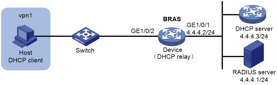
Example: Configuring a VPN DHCP user
Network configuration
As shown in Figure 10, the host in a VPN accesses the BRAS as a DHCP user. The BRAS performs AAA for the host through the RADIUS server.
Procedure
1. Configure the RADIUS server: (This section uses the Linux Free RADIUS server as an example.)
# Add BRAS IP address 4.4.4.2 and secret radius to the clients.conf file.
client 4.4.4.2/32 {
ipaddr = 4.4.4.2
netmask=32
secret=radius
}
# Add host username, password, VPN, and address pool to the users user information file. The username is the host MAC address, the password is radius, the VPN is vpn1, and the address pool is pool1.
000c29a6b656 Cleartext-Password :="radius"
Huawei-VPN-Instance :="vpn1",
Framed-Pool := " pool1"
2. Configure the DHCP server:
# Enable DHCP.
<DHCP-server> system-view
[DHCP-server] dhcp enable
# Create an IP address pool named pool1 and enter its view.
[DHCP-server] dhcp server ip-pool pool1
# Configure network segment 3.3.3.0/24 to the pool.
[DHCP-server-pool-pool1] network 3.3.3.0 24
# Configure IP address 3.3.3.1 as unavailable.
[DHCP-server-pool-pool1] forbidden-ip 3.3.3.1
[DHCP-server-pool-pool1] quit
# Configure a static IP address to specify the next hop for destination IP address 3.3.3.0.
[DHCP-server] ip route-static 3.3.3.0 24 4.4.4.2
3. Configure the BRAS:
a. Configure IP addresses for interfaces. (Details not shown.)
b. Configure a RADIUS scheme:
# Create a RADIUS scheme named rs1 and enter its view.
<Device> system-view
[Device] radius scheme rs1
# Configure primary servers and keys for authentication and accounting.
[Device-radius-rs1] primary authentication 4.4.4.1
[Device-radius-rs1] primary accounting 4.4.4.1
[Device-radius-rs1] key authentication simple radius
[Device-radius-rs1] key accounting simple radius
# Exclude the ISP name from the username sent to the RADIUS server.
[Device-radius-rs1] user-name-format without-domain
[Device-radius-rs1] quit
c. Configure the ISP domain:
# Create an ISP domain named dm1 and enter its view.
[Device] domain dm1
# Configure dm1 to use RADIUS scheme rs1.
[Device-isp-dm1] authentication ipoe radius-scheme rs1
[Device-isp-dm1] authorization ipoe radius-scheme rs1
[Device-isp-dm1] accounting ipoe radius-scheme rs1
[Device-isp-dm1] quit
d. Configure the DHCP relay:
# Enable DHCP.
[Device] dhcp enable
[Device] interface gigabitethernet 1/0/2
# Enable the DHCP relay on GigabitEthernet 1/0/2.
[Device–GigabitEthernet1/0/2] dhcp select relay
[Device–GigabitEthernet1/0/2] quit
# Create an address pool named pool1 and assign pool1 to vpn1.
[Device] dhcp server ip-pool pool1
[Device-dhcp-pool-pool1] vpn-instance vpn1
# Configure a gateway IP address for the host and enable route exporting. Route exporting automatically adds the gateway IP address and related static IP address to the routing table of vpn1.
[Device-dhcp-pool-pool1] gateway-list 3.3.3.1 export-route
# Configure an IP address for the DHCP sever
[Device-dhcp-pool-pool1] remote-server 4.4.4.3
e. Configure IPoE:
# Enable IPoE and configure Layer 2 access mode on GigabitEthernet 1/0/2.
[Device] interface gigabitethernet 1/0/2
[Device–GigabitEthernet1/0/2] ip subscriber l2-connected enable
# Enable the DHCP user.
[Device–GigabitEthernet1/0/2] ip subscriber initiator dhcp enable
# Specify dm1 as the ISP domain.
[Device–GigabitEthernet1/0/2] ip subscriber dhcp domain dm1
# Configure plaintext password radius for authentication.
[Device–GigabitEthernet1/0/2] ip subscriber password plaintext radius
[Device–GigabitEthernet1/0/2] quit
f. Configure a static route to direct the DHCP request from vpn1 to the DHCP server.
[Device] ip route-static vpn-instance vpn1 4.4.4.0 24 4.4.4.3 public
g. Configure a policy-based route to direct the traffic from the DHCP server to vpn1:
# Configure a policy named to_vpn1 with a node number of 0 and match mode of permit, and specify packets to be transmitted in vpn1.
[Device] policy-based-route to_vpn1 permit node 0
[Device-pbr-to_vpn1-0] apply access-vpn vpn-instance vpn1
[Device-pbr-to_vpn1-0] quit
# Apply to_vpn1 to GigabitEthernet 1/0/1.
[Device] interface gigabitethernet 1/0/1
[Device–GigabitEthernet1/0/1] ip policy-based-route to_vpn1
[Device–GigabitEthernet1/0/1] quit
Verifying the configuration
# Display IPoE session information to verify the configuration.
[Device] display ip subscriber session verbose
Basic:
Description : -
Username : 000c29a6b656
Domain : dm1
VPN instance : vpn1
IP address : 3.3.3.2
MAC address : 000c-29a6-b656
Service-VLAN/Customer-VLAN : -/-
Access interface : GE1/0/2
User ID : 0x380800b5
VPI/VCI(for ATM) : -/-
DHCP lease : 86400 sec
DHCP remain lease : 18400 sec
Login time : May 9 08:56:29 2014
Online time (hh:mm:ss) : 00:16:37
Service node : Slot 1 CPU 0
Type : DHCP
State : Online
AAA:
IP pool : pool1
Session idle time : N/A
Session duration : N/A, remaining: N/A
Remaining traffic : N/A
Max multicast addresses : 4
Multicast address list : N/A
QoS:
User profile : N/A
Session group profile : N/A
Inbound CAR : N/A
Outbound CAR : N/A
Flow statistic:
Uplink packets/bytes : 594341/76075648
Downlink packets/bytes : 0/0
Example: Configuring online detection
Network configuration
As shown in Figure 11, three hosts access the BRAS as unclassified-IP users. The BRAS performs AAA for the host through the RADIUS server.

Procedure
1. Configure the RADIUS server: (This section uses the Linux Free RADIUS server as an example.)
# Add BRAS IP address 4.4.4.2 and secret radius to the clients.conf file.
client 4.4.4.2/32 {
ipaddr = 4.4.4.2
netmask=32
secret=radius
}
# Add the usernames and passwords to the users user information file. The usernames are the host IP addresses and the plaintext password is radius.
2.2.2.2 Cleartext-Password :="radius"
2.2.2.3 Cleartext-Password :="radius"
2.2.2.4 Cleartext-Password :="radius"
2. Configure the BRAS:
a. Configure IP addresses for interfaces. (Details not shown.)
b. Configure a RADIUS scheme:
# Create a RADIUS scheme named rs1 and enter its view.
<Device> system-view
[Device] radius scheme rs1
# Configure primary servers and keys for authentication and accounting.
[Device-radius-rs1] primary authentication 4.4.4.1
[Device-radius-rs1] primary accounting 4.4.4.1
[Device-radius-rs1] key authentication simple radius
[Device-radius-rs1] key accounting simple radius
# Exclude the ISP name from the username sent to the RADIUS server.
[Device-radius-rs1] user-name-format without-domain
[Device-radius-rs1] quit
c. Configure the ISP domain:
# Create an ISP domain named dm1 and enter its view.
[Device] domain dm1
# Configure dm1 to use RADIUS scheme rs1.
[Device-isp-dm1] authentication ipoe radius-scheme rs1
[Device-isp-dm1] authorization ipoe radius-scheme rs1
[Device-isp-dm1] accounting ipoe radius-scheme rs1
[Device-isp-dm1] quit
d. Configure IPoE:
# Enable IPoE and configure Layer 3 access mode on GigabitEthernet 1/0/2.
[Device] interface gigabitethernet 1/0/2
[Device–GigabitEthernet1/0/2] ip subscriber routed enable
# Enable the unclassified-IP user.
[Device–GigabitEthernet1/0/2] ip subscriber initiator unclassified-ip enable
# Specify dm1 as the ISP domain.
[Device–GigabitEthernet1/0/2] ip subscriber unclassified-ip domain dm1
# Configure plaintext password radius for authentication.
[Device–GigabitEthernet1/0/2] ip subscriber password plaintext radius
# Configure online detection:
- Use ICMP detection mode.
- Set the maximum number of detection attempts to 2.
- Set the detection interval to 30 seconds.
[Device–GigabitEthernet1/0/2] ip subscriber user-detect icmp retry 2 interval 30
[Device–GigabitEthernet1/0/2] quit
Verifying the configuration
Use the display ip subscriber session command to verify that the BRAS deletes the IPoE session after the user goes offline.
Troubleshooting IPoE
DHCP clients failed to come online
Symptom
DHCP clients cannot come online, although network connections and interface IPoE configurations are correct.
Solution
To solve the problem:
1. Use debug commands or a packet analyzer to check DHCP packets from the DHCP client.
By default, DHCPv4 and DHCPv6 clients use ISP domains specified in Option 60 and Option 16, respectively.
2. If the DHCPv4 packet carries Option 60 or the DHCPv6 packet carries Option 16, verify that the ISP domain in the option exists on the BRAS.
3. If the DHCP packet does not carry Option 60 or Option 16, verify that the ISP domain specified on the interface exists on the BRAS.
4. If the problem persists, contact H3C Support.
Inter-card traffic statistics failure on an aggregate interface
Symptom
Network connections and interface IPoE configurations are correct and traffic statistics can be performed correctly for an aggregate interface with member ports on different cards. Traffic statistics fails after the member port on the initially accessed card goes down and the user accesses the member port on another card.
Solution
To solve the problem:
1. Use the service command to specify a service card for traffic statistics. Traffic will be forwarded to the specified service card for statistics. To avoid interrupting traffic statistics, make sure the specified service card is present.
Traffic statistics is performed on the card that the user initially accessed. When a member port on the initially accessed card goes down, the user traffic is redirected to the member port on another card. If no traffic exists on the initially accessed card, traffic statistics cannot be performed.
2. If the problem persists, contact H3C Support.
