- Table of Contents
- Related Documents
-
| Title | Size | Download |
|---|---|---|
| 08-WDS Configuration | 214.31 KB |
Configuration restrictions and guidelines
Mapping a mesh profile to the radio of an MP
Mapping an MP policy to the radio of an MP
Specifying a WDS working channel
Specifying a peer on the radio
Displaying and maintaining WDS
WLAN WDS configuration examples
WDS point to point connection configuration example
WDS point to multipoint connection configuration example
Overview
Wireless distribution system (WDS) provides wireless bridging links between separate LAN segments to provide connectivity between them.
Basic concepts in WDS
The WDS feature provides a single hop wireless link between two APs, including:
· Link formation—This is based on the messages exchanged between two peer nodes.
· Link security—Provides PSK plus CCMP security.
Advantages of WDS
At present, 802.11 based WLAN technologies are widely applied in the home, SOHO, and enterprise scenarios, allowing users to easily access network services.
To provide coverage, APs have to be interconnected by using cables, switches, routers and power supplies. As a result, the wireless network is complex, costly, and no longer wireless. It requires a lot time to deploy a network, especially a large scale network.
WDS delivers the following advantages:
· Low cost for high performance deployment options
· Expandable without the need for new wiring or more access points
· Easy to deploy in scenarios of metro, company, office, large warehouses, manufacturing, ports and waterfronts, and so on
Deployment scenarios
The WDS feature supports the following three topologies.
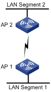
Topology 1 Peer to Peer Connection (Point to Point): In this topology, two neighbor MPs form a bridge between two LANs. In Figure 1, AP 1 and AP 2 bridge 802.3 data between LAN segments 1 and 2 by converting it to 802.11s format and sending it over a wireless link.
Figure 1 WDS point to point topology
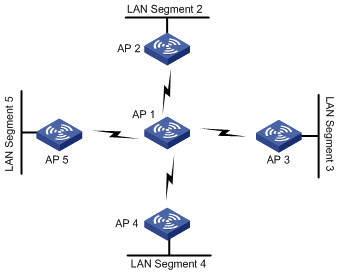
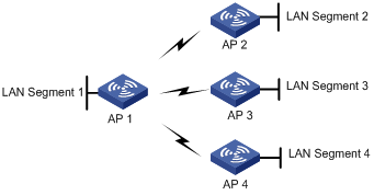
Topology 2 Centralized Bridging (Point to multipoint): In this topology, a centralized bridging device forms wireless links with multiple MPs to bridge data among multiple LAN segments. As shown in Figure 2, data transferred between different LAN segments goes via AP 1.
Figure 2 WDS point to multipoint topology
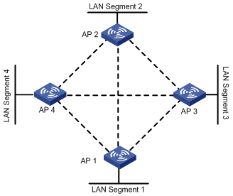
Topology 3 (Self Topology Detection and Bridging): In this topology, MPs automatically detect neighbors and form wireless links to provide wireless connectivity between LAN segments, as shown in Figure 3.
Figure 3 Self topology detection and bridging
MLSP
MLSP creates and breaks links during train movement to ensure that an active link is available on a train MP at any given time.
Terminology of MLSP
As shown in Figure 4, when the train is moving, it needs to break the existing active link with rail MP 2 and create a new active link with another rail MP.
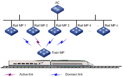
· Active Link—Logical link through which all data communication from/to a train MP happens.
· Dormant Link—Logical link over which no data transfer happens, but it satisfies all the criteria for becoming an active link.
· Proxy device—A device such as a server that is connected to a train MP for receiving traffic.
MLSP advantages
· MLSP ensures a link switch time of less than 30 milliseconds.
· MLSP works well even if the chipset gets saturated at high power level.
· MLSP achieves zero packet loss during link switch.
Operation of MLSP
MLSP establishes multiple links at any given time between a train MP and multiple rail MPs to provide link redundancy. This ensures high performance and good robustness for the network.
MLSP uses the following parameters to determine link switch. Based on the deployment, all these parameters are tunable to achieve best results.
· Link formation RSSI/link hold RSSI—This is the minimum RSSI to allow a link to be formed and held. Therefore, the minimum RSSI must be ensured at any given point in the tunnel. Otherwise, the error rate can be very high.
· Link switch margin—If the RSSI of the new link is greater than that of the current active link by the link switch margin, active link switch happens.
· Link hold time—An active link remains up within the link hold time, even if the link switch margin is reached. This mechanism is used to avoid frequent link switch.
· Link saturation RSSI—This is the upper limit of RSSI on the active link. If the value is reached, the chipset is saturated and link switch happens.
Formation of dormant links
A train MP performs active scanning to find neighboring rail MPs by sending probe requests at a very high rate. Based on probe responses received, the train MP forms a neighbor table.
After that, the train MP creates dormant links with rail MPs that have an RSSI value greater than the link formation RSSI.
Selection of active link
A train MP selects the active link from dormant links based on the following rules:
1. If no dormant link is available, the active link cannot be formed.
2. Active link switch does not happen within the link hold time, except the following two conditions:
¡ Condition 1—The active link RSSI exceeds the link saturation RSSI.
¡ Condition 2—The active link RSSI is below the link hold RSSI.
3. When the link hold timer expires, if no dormant link has an RSSI greater than the active link RSSI by the link switch margin, link switch does not happen.
4. In normal scenarios, active link switch happens when all of the following conditions are met:
¡ The link hold timer expires.
¡ The dormant link's RSSI is higher than the current active link's RSSI by the link switch margin.
¡ The dormant link RSSI is not greater than the link saturation RSSI.
¡ The RSSI of the new link should be increasing.
5. Once the RSSI of the active and dormant links have gone below the link hold RSSI, links should be broken. However, to ensure service availability in worse cases, if the active link RSSI has gone below the link hold RSSI and no dormant links exist, the active link is not broken.
Configuration restrictions and guidelines
For two APs to set up a WDS link, make sure they have the same radio type, bandwidth, and WDS settings in radio view.
WDS configuration task list
|
Remarks |
|
|
Required |
|
|
Required |
|
|
Optional |
|
|
Required |
|
|
Required |
|
|
Required |
|
|
Required |
|
|
Optional |
Configuring WDS port security
For more information about the port-security tx-key-type 11key, port-security preshared-key, and port-security port-mode commands, see Security Command Reference.
To configure WDS port security:
|
Step |
Command |
Remarks |
|
1. Enter system view. |
system-view |
N/A |
|
2. Enter WLAN mesh interface view. |
Interface wlan-mesh interface-number |
N/A |
|
3. Enable 11key negotiation. |
port-security tx-key-type 11key |
By default, 11key negotiation is disabled. |
|
4. Configure a PSK. |
port-security preshared-key { pass-phrase | raw-key } key |
By default, no PSK is configured. |
|
5. Configure the port to operate in PSK mode. |
port-security port-mode psk |
By default, the port operates in noRestrictions mode. |
Configuring a mesh profile
A mesh profile is created and mapped to an MP so that it can provide mesh services to other MPs that have the same mesh profile mapped.
|
Step |
Command |
Remarks |
|
1. Enter system view. |
system-view |
N/A |
|
2. Create a mesh profile and enter mesh profile view. |
wlan mesh-profile mesh-profile-number |
N/A |
|
3. Configure the mesh ID. |
mesh-id mesh-id-name |
By default, no mesh ID is set for the mesh profile. |
|
4. Bind a WLAN mesh interface. |
bind wlan-mesh interface-index |
By default, no interface is bound to the mesh profile. |
|
5. Configure the WDS link keep alive interval. |
link-keep-alive keep-alive-interval |
Optional. By default, the WDS link keep-alive interval is 2 seconds. |
|
6. Configure the backhaul radio rate. |
link-backhaul-rate rate-value |
Optional. The default link backhaul rate is 18 Mbps. |
|
7. Enable the mesh profile. |
mesh-profile enable |
By default, the mesh profile is disabled. |
|
8. Return to system view. |
quit |
N/A |
Configuring an MP policy
Link formation and maintenance are driven by the attributes specified in the MP policy.
To configure an MP policy:
|
Step |
Command |
Remarks |
|
1. Enter system view. |
system-view |
N/A |
|
2. Create an MP policy and enter MP policy view. |
wlan mp-policy policy-name |
By default, the radio uses the default MP policy default_mp_plcy, which cannot be deleted or modified. |
|
3. Enable link initiation. |
link-initiation enable |
Optional. By default, link initiation is enabled. |
|
4. Configure the maximum number of links. |
link-maximum-number max-link-number |
Optional. By default, the maximum number is 2. |
|
5. Configure the link formation/link hold RSSI. |
link-hold-rssi value |
Optional. The default is 15 dBm. |
|
6. Configure the link hold time. |
link-hold-time value |
Optional. The default is 4000 milliseconds. |
|
7. Configure the link switch margin. |
link-switch-margin value |
Optional. The default is 10 dBm. |
|
8. Configure the link saturation RSSI. |
link-saturation-rssi value |
Optional. The default is 150 dBm. |
|
9. Configure the probe request interval. |
probe-request-interval interval-value |
Optional. By default, the probe request interval is 1000 ms. |
|
10. Enable MLSP. |
mlsp enable |
Optional. By default, MLSP is disabled. If MLSP is disabled on a radio, the MLSP proxy MAC address configured under the current MP policy is removed. |
|
11. Configure the link rate mode. |
link rate-mode { fixed | real-time } |
Optional. The default link rate mode is fixed. |
|
|
NOTE: The mlsp enable and mlsp-proxy mac-address commands are only applicable to subway WLAN mesh networks. |
Mapping a mesh profile to the radio of an MP
For an MP to advertise mesh capabilities, a mesh profile should be mapped to the radio of the MP.
To map a mesh profile to a radio:
|
Step |
Command |
Remarks |
|
1. Enter system view. |
system-view |
N/A |
|
2. Enter radio interface view. |
interface wlan-radio interface-number |
N/A |
|
3. Map the mesh profile to the radio interface. |
mesh-profile mesh-profile-number |
By default, no mesh profile is mapped to the radio. |
Mapping an MP policy to the radio of an MP
An MP policy should be mapped to a radio so that link formation and maintenance on the radio can be driven by the attributes specified in the MP policy.
To map an MP policy to the radio of a AP:
|
Step |
Command |
Remarks |
|
1. Enter system view. |
system-view |
N/A |
|
2. Enter radio interface view. |
interface wlan-radio interface-number |
N/A |
|
3. Map the MP policy to the radio. |
mp-policy policy-name |
By default, the radio is mapped to the default MP policy. |
Specifying a WDS working channel
Use one of the following methods to specify a WDS working channel:
· Use the channel channel-number command to manually specify a WDS working channel. The APs on the two ends of a WDS link must operate on the same channel.
· Use the channel auto command to enable APs to automatically negotiate a working channel when they establish a WDS link.
No matter which method is used, as long as an AP detects radar signals on its working channel, the AP and any other AP that establish a WDS link switch to another available working channel.
In some countries, most available channels on the 802.11a band are radar channels, so H3C recommends you use the auto mode to establish WDS links on the 802.11a band.
Specifying a peer on the radio
Specify the MAC addresses of allowed peers on the local radio interface.
To specify a peer MAC address on a radio interface:
|
Step |
Command |
Remarks |
|
1. Enter system view. |
system-view |
N/A |
|
2. Enter radio interface view. |
interface wlan-radio interface-number |
N/A |
|
3. Specify the MAC address of a permitted peer. |
mesh peer-mac-address mac-address |
By default, the radio has no peer MAC address configured, and all neighbors are permitted. |
Enabling waveguide
Waveguide is a medium for bidirectional signal transmission between train and rail MPs. It has high bandwidth, low signal loss, high availability, and interference resistance capability. To ensure rapid and reliable data exchange between rail and train MPs, enable waveguide on rail MPs for them to transmit radio signals through waveguide.
To enable waveguide:
|
Step |
Command |
Remarks |
|
1. Enter system view. |
system-view |
N/A |
|
2. Enter MP policy view. |
wlan mp-policy policy-name |
By default, the radio uses the default MP policy default_mp_plcy, which cannot be deleted or modified. |
|
3. Enable MLSP. |
mlsp enable |
By default, MLSP is disabled. If MLSP is disabled, the MLSP proxy MAC address configured under the current MP policy is removed. |
|
4. Enable waveguide. |
wave-guide enable |
By default, waveguide is disabled. |
Displaying and maintaining WDS
|
Task |
Command |
Remarks |
|
Display WDS link information. |
display wlan mesh-link { mesh-profile mesh-profile-number | radio radio-number | peer-mac-address mac-address | all } [ | { begin | exclude | include } regular-expression ] |
Available in any view. |
|
Display mesh profile information. |
display wlan mesh-profile { mesh-profile-number | all } [ | { begin | exclude | include } regular-expression ] |
Available in any view. |
|
Display MP policy information. |
display wlan mp-policy { mp-policy-name | all } [ | { begin | exclude | include } regular-expression ] |
Available in any view. |
WLAN WDS configuration examples
WDS point to point connection configuration example
Network requirements
In an outdoor environment as shown in Figure 5, connecting the two LAN segments with cables is time-consuming and cost ineffective. Therefore, you can connect the two LAN segments with a WDS link.
· Connect AP 1 and AP 2 to different LAN segments.
· Configure AP 1 and AP 2 to use channel 153 to establish the WDS link.
· Configure preshared key 12345678 to ensure WDS link security.
Configuration procedure
Because the WDS point to point configuration made on the two APs are similar, the following only gives the configuration on AP 1.
# Enable port security.
<AP1> system-view
[AP1] port-security enable
# Configure a WLAN-mesh interface, set the port security mode of the interface to psk (with preshared key 12345678), and enable 11key negotiation.
[AP1] interface WLAN-MESH 1
[AP1-WLAN-MESH1] port-security port-mode psk
[AP1-WLAN-MESH1] port-security preshared-key pass-phrase 12345678
[AP1-WLAN-MESH1] port-security tx-key-type 11key
[AP1-WLAN-MESH1] quit
# Configure the mesh profile.
[AP1] wlan mesh-profile 1
[AP1-wlan-mshp-1] mesh-id outdoor
[AP1-wlan-mshp-1] bind WLAN-MESH 1
[AP1-wlan-mshp-1] mesh-profile enable
[AP1-wlan-mshp-1] quit
# Configure the radio interface to use 802.11a and channel 153.
[AP1] interface WLAN-Radio 1/0/1
[AP1-WLAN-Radio1/0/1] radio-type dot11a
[AP1-WLAN-Radio1/0/1] channel 153
# Configure the peer MAC address on the radio interface: the MAC address of the radio interface on AP 2.
[AP1-WLAN-Radio1/0/1] mesh peer-mac-address 0ebb-01bb-bb00
# Map the mesh profile to the radio interface.
[AP1-WLAN-Radio1/0/1] mesh-profile 1
[AP1-WLAN-Radio1/0/1] return
Verifying the configuration
After the devices on the two ends of the WDS link are configured, you can use the display command to view whether the WDS link has been established successfully.
# View the WDS link information on AP 1.
<AP1> display wlan mesh-link all
Peer Link Information
-------------------------------------------------------------------------------
Nbr-Mac BSSID Interface Link-state Uptime (hh:mm:ss)
0ebb-01bb-bb00 000f-e212-1200 WLAN-MESHLINK62 Active 0:17:59
-------------------------------------------------------------------------------
The output shows that the WDS link between AP 1 and AP 2 has been established successfully.
WDS point to multipoint connection configuration example
Network requirement
As shown in Figure 6, enable AP 1 to establish a WDS link with AP 2, AP 3, and AP 4.
Configuration procedure
The WDS point to multipoint configuration is the same as point to point WDS configuration. Note the following when configuring WDS:
· Configure a neighbor MAC address for each radio interface (otherwise, WDS links may be set up between AP 2, AP 3, and AP 4).
· Set the maximum number of WDS links allowed. The default value is 2. It should be set to 3 for AP 1 in this example.
Verifying the configuration
· Issuing the display wlan mesh-link all command on AP 1 should display that AP 1 has established a WDS link with AP 2, AP 3 and AP 4.
· Issuing the display wlan mesh-link all command on AP 2, AP 3 and AP 4 should display that they each have established a WDS link with AP 1.
