- Table of Contents
-
- 02-Layer 2-LAN Switching Configuration Guide
- 00-Preface
- 01-Ethernet interface configuration
- 02-Loopback and null interface configuration
- 03-Bulk interface configuration
- 04-MAC address table configuration
- 05-Ethernet link aggregation configuration
- 06-Port isolation configuration
- 07-Spanning tree configuration
- 08-BPDU tunneling configuration
- 09-VLAN configuration
- 10-GVRP configuration
- 11-LLDP configuration
- 12-Service loopback group configuration
- 13-MVRP configuration
- Related Documents
-
| Title | Size | Download |
|---|---|---|
| 05-Ethernet link aggregation configuration | 252.16 KB |
Configuring Ethernet link aggregation
Aggregating links in static mode
Aggregating links in dynamic mode
Load sharing criteria for link aggregation groups
Ethernet link aggregation configuration task list
Configuring an aggregation group
Configuring a static aggregation group
Configuring a dynamic aggregation group
Configuring an aggregate interface·
Configuring the description of an aggregate interface
Enabling link state traps for an aggregate interface
Setting the minimum number of Selected ports for an aggregation group
Shutting down an aggregate interface·
Restoring the default settings for an aggregate interface
Configuring load sharing criteria for link aggregation groups
Displaying and maintaining Ethernet link aggregation
Ethernet link aggregation configuration examples
Layer 2 static aggregation configuration example
Layer 2 dynamic aggregation configuration example
Layer 2 aggregation load sharing configuration example
This chapter describes how to configure Ethernet link aggregation.
Overview
Ethernet link aggregation, or simply link aggregation, combines multiple physical Ethernet ports into one logical link, called an "aggregate link." Link aggregation delivers the following benefits:
· Increases bandwidth beyond the limits of any single link. In an aggregate link, traffic is distributed across the member ports.
· Improves link reliability. The member ports dynamically back up one another. When a member port fails, its traffic is automatically switched to other member ports.
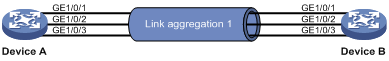
As shown in Figure 1, Device A and Device B are connected by three physical Ethernet links. These physical Ethernet links are combined into an aggregate link, Link Aggregation 1. The bandwidth of this aggregate link is as high as the total bandwidth of the three physical Ethernet links. At the same time, the three Ethernet links back up one another.
Figure 1 Ethernet link aggregation
Basic concepts
This section describes the basic concepts of link aggregation.
Aggregation group, member port, and aggregate interface
Link aggregation is implemented through link aggregation groups. An aggregation group is a group of Ethernet interfaces combined together, which are called "member ports" of the aggregation group. For each aggregation group, a logical interface, called an "aggregate interface", is created. To an upper layer entity that uses the link aggregation service, a link aggregation group appears to be a single logical link and data traffic is transmitted through the aggregate interface.
In this chapter, aggregate interfaces refer to bridge-aggregation (BAGG) interfaces, also called Layer 2 aggregate interfaces. When you create an aggregate interface, the switch automatically creates an aggregation group of the same type and number as the aggregate interface. For example, when you create interface Bridge-Aggregation 1, Layer 2 aggregation group 1 is created.
You can assign Layer 2 Ethernet interfaces only to a Layer 2 aggregation group.
The rate of an aggregate interface equals the total rate of its member ports in Selected state, and its duplex mode is the same as the selected member ports. For more information about the states of member ports in an aggregation group, see "Aggregation states of member ports in an aggregation group."
Aggregation states of member ports in an aggregation group
A member port in an aggregation group can be in either of the following aggregation states:
· Selected—A Selected port can forward user traffic.
· Unselected—An Unselected port cannot forward user traffic.
When a Selected port fails, an Unselected port might become a Selected port and forward user traffic.
Operational key
When aggregating ports, the system automatically assigns each port an operational key based on port information such as port rate and duplex mode. Any change to this information triggers a recalculation of the operational key.
In an aggregation group, all selected member ports are assigned the same operational key.
Configuration classes
Every configuration setting on a port might affect its aggregation state. Port configurations include the following classes:
· Port attribute configurations—Include port rate, duplex mode, and link status (up/down). These are the most basic port configurations.
· Class-two configurations—A member port can be placed in Selected state only if it has the same class-two configurations as the aggregate interface.
Class-two configurations made on an aggregate interface are automatically synchronized to all member ports of the interface. These configurations are retained on the member ports even after the aggregate interface is removed.
Any class-two configuration change might affect the aggregation state of link aggregation member ports and ongoing traffic. To be sure that you are aware of the risk, the system displays a warning message every time you attempt to change a class-two configuration setting on a member port.
Table 1 Class-two configurations
|
Feature |
Considerations |
|
Port isolation |
Whether the port has joined an isolation group, and the isolation group to which the port belongs. |
|
QinQ |
QinQ enable state (enable/disable), TPID for VLAN tags, outer VLAN tags to be added, inner-to-outer VLAN priority mappings, inner-to-outer VLAN tag mappings, inner VLAN ID substitution mappings. |
|
VLAN |
Permitted VLAN IDs, port VLAN ID (PVID), link type (trunk, hybrid, or access), IP subnet-based VLAN configuration, protocol-based VLAN configuration, VLAN tagging mode. |
|
MAC address learning |
MAC address learning capability. |
· Class-one configurations—Include settings that do not affect the aggregation state of the member port even if they are different from those on the aggregate interface. GVRP and the spanning tree settings are examples of class-one configurations.
The class-one configuration for a member port is effective only when the member port leaves the aggregation group.
Reference port
When setting the aggregation state of the ports in an aggregation group, the system automatically picks a member port as the reference port. A Selected port must have the same port attributes and class-two configurations as the reference port. For how to choose a reference port, see Choosing a reference port in the section Aggregating links in static mode or Choosing a reference port in the section Aggregating links in dynamic mode.
Link aggregation modes
Link aggregation has the following modes: dynamic and static. Dynamic link aggregation uses Link Aggregation Control Protocol (LACP) and static link aggregation does not. Table 2 compares the two aggregation modes.
Table 2 A comparison between static and dynamic aggregation modes
|
Aggregation mode |
LACP status on member ports |
Pros |
Cons |
|
Static |
Disabled |
Aggregation is stable. Peers do not affect the aggregation state of the member ports. |
The member ports do not adjust the aggregation state according to that of the peer ports. The administrator must manually maintain link aggregations. |
|
Dynamic |
Enabled |
The peer systems maintain the aggregation state of the member ports automatically. |
Aggregation is unstable. The aggregation state of the member ports is susceptible to network changes. |
The following points apply to a dynamic link aggregation group:
· A Selected port can receive and send link aggregation control protocol data units (LACPDUs).
· An Unselected port can receive and send LACPDUs only if it is up and has the same class-two configurations as the aggregate interface.
LACP
The IEEE 802.3ad LACP enables dynamic aggregation of physical links. It uses link aggregation control protocol data units (LACPDUs) for exchanging aggregation information between LACP-enabled devices.
· LACP functions
The IEEE 802.3ad LACP offers basic LACP functions and extended LACP functions, as described in Table 3.
Table 3 Basic and extended LACP functions
|
Category |
Description |
|
Basic LACP functions |
Implemented through the basic LACPDU fields, including the system LACP priority, system MAC address, port aggregation priority, port number, and operational key. Each member port in a LACP-enabled aggregation group exchanges the preceding information with its peer. When a member port receives an LACPDU, it compares the received information with the information received on the other member ports. In this way, the two systems reach an agreement on which ports should be placed in Selected state. |
|
Extended LACP functions |
Implemented by extending the LACPDU with new TLV fields. |
· LACP priorities
LACP priorities have the following types: system LACP priority and port aggregation priority.
The smaller the priority value, the higher the priority.
|
Type |
Description |
|
System LACP priority |
Used by two peer devices (or systems) to determine which one is superior in link aggregation. In dynamic link aggregation, the system that has higher system LACP priority sets the Selected state of member ports on its side first, and then the system that has lower priority sets the port state accordingly. |
|
Port aggregation priority |
Determines the likelihood of a member port to be selected on a system. The higher the port aggregation priority, the higher the likelihood. |
· LACP timeout interval
The LACP timeout interval specifies how long a member port waits to receive LACPDUs from the peer port. If a local member port fails to receive LACPDUs from the peer within three times the LACP timeout interval, the member port assumes that the peer port has failed. You can configure the LACP timeout interval as either the short timeout interval (1 second) or the long timeout interval (30 seconds).
Aggregating links in static mode
LACP is disabled on the member ports in a static aggregation group. You must manually maintain the aggregation state of the member ports.
When you aggregate links in static mode, follow these guidelines:
· To make sure that you have stable aggregation state and service continuity, do not change port attributes or class-two configurations on any member port.
· If a static aggregation group has reached the limit on Selected ports, any port that joins the group is placed in Unselected state to avoid traffic interruption on the current Selected ports. Avoid this situation, however, because it might cause the aggregation state of a port to change after a reboot.
The static link aggregation process comprises the following tasks:
· Setting the aggregation state of each member port
Choosing a reference port
The system chooses a reference port from the member ports that:
· Are in up state.
· Have the same class-two configurations as the aggregate interface.
The candidate ports are sorted by aggregation priority, duplex, and speed in the following order:
· Lowest aggregation priority value
· Full duplex/high speed
· Full duplex/low speed
· Half duplex/high speed
· Half duplex/low speed
The one at the top is chosen as the reference port. If two ports have the same aggregation priority, duplex mode, and speed, the one with the lower port number is chosen.
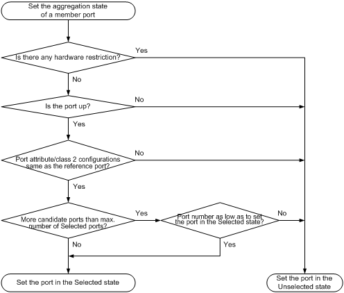
Setting the aggregation state of each member port
After choosing the reference port, the static aggregation group sets the aggregation state of each member port.
Figure 2 Setting the aggregation state of a member port in a static aggregation group
Aggregating links in dynamic mode
LACP is automatically enabled on all member ports in a dynamic aggregation group. The protocol automatically maintains the aggregation state of ports.
When you aggregate links in dynamic mode, follow these guidelines:
· A dynamic link aggregation group preferably sets full-duplex ports as the Selected ports, and will set one, and only one, half-duplex port as a Selected port when none of the full-duplex ports can be selected or only half-duplex ports exist in the group.
· To make sure that you have stable aggregation state and service continuity, do not change port attributes or class-two configurations on any member port.
· In a dynamic aggregation group, when the aggregation state of a local port changes, the aggregation state of the peer port changes.
· A port that joins a dynamic aggregation group after the Selected port limit has been reached is placed in Selected state if it is more eligible for being selected than a current member port.
The dynamic link aggregation process comprises the following tasks:
· Setting the aggregation state of each member port
Choosing a reference port
The local system (the actor) and the remote system (the partner) negotiate a reference port by using the following workflow:
1. The systems compare the system ID (which comprises the system LACP priority and the system MAC address). The system with the lower LACP priority value is chosen. If they are the same, the systems compare the system MAC addresses. The system with the lower MAC address is chosen.
2. The system with the smaller system ID chooses the port with the smallest port ID as the reference port. A port ID comprises a port aggregation priority and a port number. The port with the lower aggregation priority value is chosen. If two ports have the same aggregation priority, the system compares their port numbers. The port with the smaller port number is chosen.
Setting the aggregation state of each member port
After the reference port is chosen, the system with the lower system ID sets the state of each member port in the dynamic aggregation group on its side.
Figure 3 Setting the state of a member port in a dynamic aggregation group
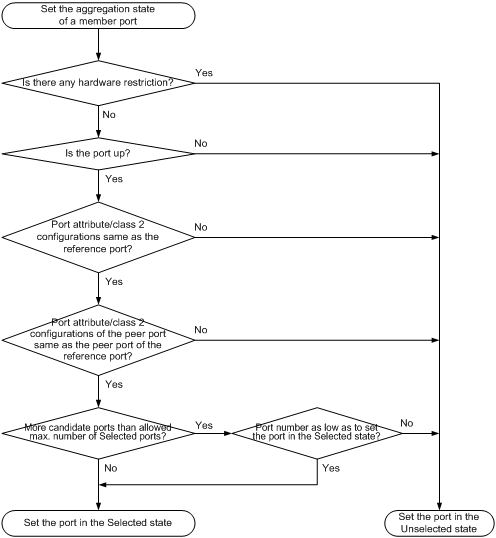
Meanwhile, the system with the higher system ID, which has identified the aggregation state changes on the remote system, sets the aggregation state of local member ports as the same as their peer ports.
Load sharing criteria for link aggregation groups
In a link aggregation group, traffic can be load-shared across the selected member ports based on a set of criteria, depending on your configuration.
You can choose one of the following criteria or any combination for load sharing:
· MAC addresses
· Source/Destination service port numbers
· Ingress ports
· Source/Destination IP addresses
Ethernet link aggregation configuration task list
|
Task |
Remarks |
|
|
Select either task. |
||
|
Optional. |
||
|
Optional. |
||
|
Setting the minimum number of Selected ports for an aggregation group |
Optional. |
|
|
Optional. |
||
|
Optional. |
||
|
Configuring load sharing criteria for link aggregation groups |
Optional. |
|
Configuring an aggregation group
|
|
CAUTION: Removing an aggregate interface also removes the corresponding aggregation group. At the same time, all member ports leave the aggregation group. |
You cannot assign a port to a Layer 2 aggregation group if any of the features listed in Table 5 is configured on the port.
Table 5 Features incompatible with Layer 2 aggregation groups
|
Feature |
Reference |
|
RRPP |
RRPP in High Availability Configuration Guide |
|
MAC authentication |
MAC authentication in Security Configuration Guide |
|
Port security |
Port security in Security Configuration Guide |
|
802.1X |
802.1X in Security Configuration Guide |
|
Ports specified as source interfaces in portal-free rules |
Portal in Security Configuration Guide |
Configuring a static aggregation group
Configuring a Layer 2 static aggregation group
|
Step |
Command |
Remarks |
|
1. Enter system view. |
system-view |
N/A |
|
2. Create a Layer 2 aggregate interface and enter Layer 2 aggregate interface view. |
interface bridge-aggregation interface-number |
When you create a Layer 2 aggregate interface, the system automatically creates a Layer 2 static aggregation group numbered the same. |
|
3. Exit to system view. |
quit |
N/A |
|
4. Assign a Layer 2 Ethernet interface to the aggregation group. |
a. interface interface-type interface-number b. port link-aggregation group number |
Repeat this step to assign more Layer 2 Ethernet interfaces to the aggregation group. |
|
5. Assign the port an aggregation priority. |
link-aggregation port-priority port-priority |
Optional. By default, the aggregation priority of a port is 32768. Changing the aggregation priority of a port might affect the aggregation state of the ports in the static aggregation group. |
Configuring a dynamic aggregation group
To guarantee a successful dynamic aggregation, make sure that the peer ports of the ports aggregated at one end are also aggregated. The two ends can automatically negotiate the aggregation state of each member port.
Configuring a Layer 2 dynamic aggregation group
|
Step |
Command |
Remarks |
|
1. Enter system view. |
system-view |
N/A |
|
2. Set the system LACP priority. |
lacp system-priority system-priority |
Optional. By default, the system LACP priority is 32768. Changing the system LACP priority might affect the aggregation state of the ports in a dynamic aggregation group. |
|
3. Create a Layer 2 aggregate interface and enter Layer 2 aggregate interface view. |
interface bridge-aggregation interface-number |
When you create a Layer 2 aggregate interface, the system automatically creates a Layer 2 static aggregation group numbered the same. |
|
4. Configure the aggregation group to operate in dynamic aggregation mode. |
link-aggregation mode dynamic |
By default, an aggregation group operates in static aggregation mode. |
|
5. Exit to system view. |
quit |
N/A |
|
6. Assign a Layer 2 Ethernet interface to the aggregation group. |
a. interface interface-type interface-number b. port link-aggregation group number |
Repeat this step to assign more Layer 2 Ethernet interfaces to the aggregation group. |
|
7. Assign the port an aggregation priority. |
link-aggregation port-priority port-priority |
Optional. By default, the aggregation priority of a port is 32768. Changing the aggregation priority of a port might affect the aggregation state of the ports in the dynamic aggregation group. |
|
8. Set the LACP timeout interval on the port to the short timeout interval (1 second). |
lacp period short |
Optional. By default, the LACP timeout interval on a port is the long timeout interval (30 seconds). |
Configuring an aggregate interface
Most of the configurations that can be performed on Layer 2 Ethernet interfaces can also be performed on Layer 2 aggregate interfaces.
Configuring the description of an aggregate interface
You can configure the description of an aggregate interface for administration purposes such as describing the purpose of the interface.
To configure the description of an aggregate interface:
|
Step |
Command |
Remarks |
|
1. Enter system view. |
system-view |
N/A |
|
2. Enter Layer 2 aggregate interface view. |
interface bridge-aggregation interface-number |
N/A |
|
3. Configure the description of the aggregate interface. |
description text |
Optional. By default, the description of an interface is in the format of interface-name Interface, such as Bridge-Aggregation1 Interface. |
Enabling link state traps for an aggregate interface
You can configure an aggregate interface to generate linkUp trap messages when its link goes up and linkDown trap messages when its link goes down. For more information, see Network Management and Monitoring Configuration Guide.
To enable link state traps for an aggregate interface:
|
Step |
Command |
Remarks |
|
1. Enter system view. |
system-view |
N/A |
|
2. Enable the trap function globally. |
snmp-agent trap enable [ standard [ linkdown | linkup ] * ] |
Optional. By default, link state trapping is enabled globally and on all interfaces. |
|
3. Enter Layer 2 aggregate interface view. |
interface bridge-aggregation interface-number |
N/A |
|
4. Enable link state traps for the aggregate interface. |
enable snmp trap updown |
Optional. Enabled by default. |
Setting the minimum number of Selected ports for an aggregation group
The bandwidth of an aggregate link increases along with the number of selected member ports. To avoid congestion caused by insufficient Selected ports on an aggregate link, you can set the minimum number of Selected ports required for bringing up the specific aggregate interface.
This minimum threshold setting affects the aggregation state of both aggregation member ports and the aggregate interface:
· All member ports change to the Unselected state and the link of the aggregate interface goes down, when the number of member ports eligible for being selected is smaller than the minimum threshold.
· When the minimum threshold is reached, the eligible member ports change to the Selected state, and the link of the aggregate interface goes up.
Configuration restrictions and guidelines
When you set the minimum number of Selected ports for an aggregation group, follow these restrictions and guidelines:
· Configuring the minimum number of Selected ports required to bring up an aggregation group might cause all the member ports in the aggregation group to become unselected.
· Make sure the minimum number of selected ports is the same as that on the peer.
Configuration procedure
To set the minimum number of Selected ports for an aggregation group:
|
Step |
Command |
Remarks |
|
1. Enter system view. |
system-view |
N/A |
|
2. Enter Layer 2 aggregate interface view. |
interface bridge-aggregation interface-number |
N/A |
|
3. Set the minimum number of Selected ports for the aggregation group. |
link-aggregation selected-port minimum number |
Not specified by default. |
Shutting down an aggregate interface
Shutting down or bringing up an aggregate interface affects the aggregation state and link state of ports in the corresponding aggregation group in the following ways:
· When an aggregate interface is shut down, all Selected ports in the corresponding aggregation group become unselected and their link state becomes down.
· When an aggregate interface is brought up, the aggregation state of ports in the corresponding aggregation group is recalculated and their link state becomes up.
To shut down an aggregate interface:
|
Step |
Command |
Remarks |
|
1. Enter system view. |
system-view |
N/A |
|
2. Enter Layer 2 aggregate interface view. |
interface bridge-aggregation interface-number |
N/A |
|
3. Shut down the aggregate interface. |
shutdown |
By default, aggregate interfaces are up. |
Restoring the default settings for an aggregate interface
|
Step |
Command |
Remarks |
|
1. Enter system view. |
system-view |
N/A |
|
2. Enter Layer 2 aggregate interface view. |
interface bridge-aggregation interface-number |
N/A |
|
3. Restore the default settings for the aggregate interface. |
default |
N/A |
Configuring load sharing criteria for link aggregation groups
You can determine how traffic is load-shared in a link aggregation group by configuring load sharing criteria. The criteria can be source/destination MAC addresses, source/destination service port numbers, ingress ports, source/destination IP addresses, or protocol numbers, or any combination.
You can configure global or group-specific load sharing criteria. A link aggregation group preferentially uses the group-specific load sharing criteria. If no group-specific load sharing criteria is available, the group uses the global load sharing criteria.
Configuration restrictions and guidelines
The load sharing criteria configuration applies to only unicast packets, and can change the load sharing criteria for unicast packets. Broadcast packets and multicast packets always use the default load sharing criteria.
Configuring the global link-aggregation load sharing criteria
|
Step |
Command |
Remarks |
|
1. Enter system view. |
system-view |
N/A |
|
2. Configure the global link-aggregation load sharing criteria. |
link-aggregation load-sharing mode { destination-ip | destination-mac | destination-port | ingress-port | source-ip | source-mac | source-port | } * |
By default, the system selects the global load sharing criteria according to the packet type. |
In system view, the WX5540E switching engine supports the following load sharing criteria and combinations:
· Load sharing criteria automatically determined based on the packet type
· Source IP address
· Destination IP address
· Source MAC address
· Destination MAC address
· Source IP address and destination IP address
· Source IP address and source port
· Destination IP address and destination port
· Source IP address, source port, destination IP address, and destination port
· Any combination of incoming port, source MAC address, and destination MAC address
Configuring group-specific load sharing criteria
|
Step |
Command |
Remarks |
|
1. Enter system view. |
system-view |
N/A |
|
2. Enter Layer 2 aggregate interface view. |
interface bridge-aggregation interface-number |
N/A |
|
3. Configure the load sharing criteria for the aggregation group. |
link-aggregation load-sharing mode { destination-ip | destination-mac | source-ip | source-mac } * |
The default load sharing criteria are the same as the global load sharing criteria. |
In Layer 2 aggregate interface view, the WX5540E switching engine supports the following load sharing criteria and combinations:
· Load sharing criteria automatically determined based on the packet type
· Source IP address
· Destination IP address
· Source MAC address
· Destination MAC address
· Destination IP address and source IP address
· Destination MAC address and source MAC address
Displaying and maintaining Ethernet link aggregation
|
Task |
Command |
Remarks |
|
Display information about an aggregate interface or multiple aggregate interfaces. |
display interface [ bridge-aggregation ] [ brief [ down ] ] [ | { begin | exclude | include } regular-expression ] display interface bridge-aggregation interface-number [ brief ] [ | { begin | exclude | include } regular-expression ] |
Available in any view. |
|
Display the local system ID. |
display lacp system-id [ | { begin | exclude | include } regular-expression ] |
Available in any view. |
|
Display the global or group-specific link-aggregation load sharing criteria. |
display link-aggregation load-sharing mode [ interface [ bridge-aggregation interface-number ] ] [ | { begin | exclude | include } regular-expression ] |
Available in any view. |
|
Display detailed link aggregation information for link aggregation member ports. |
display link-aggregation member-port [ interface-list ] [ | { begin | exclude | include } regular-expression ] |
Available in any view. |
|
Display summary information about all aggregation groups. |
display link-aggregation summary [ | { begin | exclude | include } regular-expression ] |
Available in any view. |
|
Display detailed information about a specific or all aggregation groups. |
display link-aggregation verbose [ bridge-aggregation [ interface-number ] ] [ | { begin | exclude | include } regular-expression ] |
Available in any view. |
|
Clear LACP statistics for a specific or all link aggregation member ports. |
reset lacp statistics [ interface interface-list ] |
Available in user view. |
|
Clear statistics for a specific or all aggregate interfaces. |
reset counters interface [ bridge-aggregation [ interface-number ] ] |
Available in user view. |
Ethernet link aggregation configuration examples
In an aggregation group, only ports that have the same port attributes and class-two configurations (see "Configuration classes") as the reference port (see "Reference port") can operate as Selected ports. Make sure that all member ports have the same port attributes and class-two configurations as the reference port. The other settings only need to be configured on the aggregate interface, not on the member ports.
Layer 2 static aggregation configuration example
Network requirements
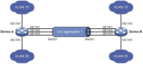
As shown in Figure 4:
· Configure a Layer 2 static aggregation group on Device A and Device B. Enable VLAN 10 at one end of the aggregate link to communicate with VLAN 10 at the other end, and VLAN 20 at one end to communicate with VLAN 20 at the other end.
· Enable traffic to be load-shared across aggregation group member ports based on the source and destination MAC addresses.
Configuration procedure
1. Configure Device A:
# Create VLAN 10, and assign port GigabitEthernet 1/0/4 to VLAN 10.
<DeviceA> system-view
[DeviceA] vlan 10
[DeviceA-vlan10] port gigabitethernet 1/0/4
[DeviceA-vlan10] quit
# Create VLAN 20, and assign port GigabitEthernet 1/0/5 to VLAN 20.
[DeviceA] vlan 20
[DeviceA-vlan20] port gigabitethernet 1/0/5
[DeviceA-vlan20] quit
# Create Layer 2 aggregate interface Bridge-Aggregation 1.
[DeviceA] interface bridge-aggregation 1
[DeviceA-Bridge-Aggregation1] quit
# Assign ports GigabitEthernet 1/0/1 through GigabitEthernet 1/0/3 to link aggregation group 1.
[DeviceA] interface gigabitethernet 1/0/1
[DeviceA-GigabitEthernet1/0/1] port link-aggregation group 1
[DeviceA-GigabitEthernet1/0/1] quit
[DeviceA] interface gigabitethernet 1/0/2
[DeviceA-GigabitEthernet1/0/2] port link-aggregation group 1
[DeviceA-GigabitEthernet1/0/2] quit
[DeviceA] interface gigabitethernet 1/0/3
[DeviceA-GigabitEthernet1/0/3] port link-aggregation group 1
[DeviceA-GigabitEthernet1/0/3] quit
# Configure Layer 2 aggregate interface Bridge-Aggregation 1 as a trunk port and assign it to VLANs 10 and 20.
[DeviceA] interface bridge-aggregation 1
[DeviceA-Bridge-Aggregation1] port link-type trunk
[DeviceA-Bridge-Aggregation1] port trunk permit vlan 10 20
Please wait... Done.
Configuring GigabitEthernet1/0/1... Done.
Configuring GigabitEthernet1/0/2... Done.
Configuring GigabitEthernet1/0/3... Done.
[DeviceA-Bridge-Aggregation1] quit
# Configure Device A to use the source and destination MAC addresses of packets as the global link-aggregation load sharing criteria.
[DeviceA] link-aggregation load-sharing mode source-mac destination-mac
2. Configure Device B in the same way Device A is configured.
Verifying the configuration
# Display summary information about all aggregation groups on Device A.
[DeviceA] display link-aggregation summary
Aggregation Interface Type:
BAGG -- Bridge-Aggregation
Aggregation Mode: S -- Static, D -- Dynamic
Loadsharing Type: Shar -- Loadsharing, NonS -- Non-Loadsharing
Actor System ID: 0x8000, 000f-e2ff-0001
AGG AGG Partner ID Select Unselect Share
Interface Mode Ports Ports Type
-------------------------------------------------------------------------------
BAGG1 S none 3 0 Shar
The output shows that link aggregation group 1 is a load-shared Layer 2 static aggregation group and it contains three Selected ports.
# Display the global link-aggregation load sharing criteria on Device A.
[DeviceA] display link-aggregation load-sharing mode
Link-Aggregation Load-Sharing Mode:
destination-mac address, source-mac address
The output shows that all link aggregation groups created on the device perform load sharing based on source and destination MAC addresses.
Layer 2 dynamic aggregation configuration example
Network requirements
As shown in Figure 5:
· Configure a Layer 2 dynamic aggregation group on Device A and Device B. Enable VLAN 10 at one end of the aggregate link to communicate with VLAN 10 at the other end, and VLAN 20 at one end to communicate with VLAN 20 at the other end.
· Enable traffic to be load-shared across aggregation group member ports based on source and destination MAC addresses.

Configuration procedure
1. Configure Device A:
# Create VLAN 10, and assign the port GigabitEthernet 1/0/4 to VLAN 10.
<DeviceA> system-view
[DeviceA] vlan 10
[DeviceA-vlan10] port gigabitethernet 1/0/4
[DeviceA-vlan10] quit
# Create VLAN 20, and assign the port GigabitEthernet 1/0/5 to VLAN 20.
[DeviceA] vlan 20
[DeviceA-vlan20] port gigabitethernet 1/0/5
[DeviceA-vlan20] quit
# Create Layer 2 aggregate interface Bridge-Aggregation 1, and configure the link aggregation mode as dynamic.
[DeviceA] interface bridge-aggregation 1
[DeviceA-Bridge-Aggregation1] link-aggregation mode dynamic
# Assign ports GigabitEthernet 1/0/1 through GigabitEthernet 1/0/3 to link aggregation group 1 one at a time.
[DeviceA] interface gigabitethernet 1/0/1
[DeviceA-GigabitEthernet1/0/1] port link-aggregation group 1
[DeviceA-GigabitEthernet1/0/1] quit
[DeviceA] interface gigabitethernet 1/0/2
[DeviceA-GigabitEthernet1/0/2] port link-aggregation group 1
[DeviceA-GigabitEthernet1/0/2] quit
[DeviceA] interface gigabitethernet 1/0/3
[DeviceA-GigabitEthernet1/0/3] port link-aggregation group 1
[DeviceA-GigabitEthernet1/0/3] quit
# Configure Layer 2 aggregate interface Bridge-Aggregation 1 as a trunk port and assign it to VLANs 10 and 20.
[DeviceA] interface bridge-aggregation 1
[DeviceA-Bridge-Aggregation1] port link-type trunk
[DeviceA-Bridge-Aggregation1] port trunk permit vlan 10 20
Please wait... Done.
Configuring GigabitEthernet1/0/1... Done.
Configuring GigabitEthernet1/0/2... Done.
Configuring GigabitEthernet1/0/3... Done.
[DeviceA-Bridge-Aggregation1] quit
# Configure the device to use the source and destination MAC addresses of packets as the global link-aggregation load sharing criteria.
[DeviceA] link-aggregation load-sharing mode source-mac destination-mac
2. Configure Device B in the same way Device A is configured.
Verifying the configuration
# Display summary information about all aggregation groups on Device A.
[DeviceA] display link-aggregation summary
Aggregation Interface Type:
BAGG -- Bridge-Aggregation
Aggregation Mode: S -- Static, D -- Dynamic
Loadsharing Type: Shar -- Loadsharing, NonS -- Non-Loadsharing
Actor System ID: 0x8000, 000f-e2ff-0001
AGG AGG Partner ID Select Unselect Share
Interface Mode Ports Ports Type
-------------------------------------------------------------------------------
BAGG1 D 0x8000, 000f-e2ff-0002 3 0 Shar
The output shows that link aggregation group 1 is a load-shared Layer 2 dynamic aggregation group, and it contains three Selected ports.
# Display the global link-aggregation load sharing criteria on Device A.
[DeviceA] display link-aggregation load-sharing mode
Link-Aggregation Load-Sharing Mode:
destination-mac address, source-mac address
The output shows that all link aggregation groups created on the device perform load sharing based on source and destination MAC addresses.
Layer 2 aggregation load sharing configuration example
Network requirements
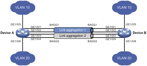
As shown in Figure 6:
· Configure two Layer 2 static aggregation groups (1 and 2) on Device A and Device B, and enable VLAN 10 at one end of the aggregate link to communicate with VLAN 10 at the other end, and VLAN 20 at one end to communicate with VLAN 20 at the other end.
· Configure the load sharing criterion for link aggregation group 1 as the source MAC addresses of packets and the load sharing criterion for link aggregation group 2 as the destination MAC addresses of packets to enable traffic to be load-shared across aggregation group member ports.
Configuration procedure
1. Configure Device A:
# Create VLAN 10, and assign the port GigabitEthernet 1/0/5 to VLAN 10.
<DeviceA> system-view
[DeviceA] vlan 10
[DeviceA-vlan10] port gigabitethernet 1/0/5
[DeviceA-vlan10] quit
# Create VLAN 20, and assign the port GigabitEthernet 1/0/6 to VLAN 20.
<DeviceA> system-view
[DeviceA] vlan 20
[DeviceA-vlan20] port gigabitethernet 1/0/6
[DeviceA-vlan20] quit
# Create Layer 2 aggregate interface Bridge-Aggregation 1, and configure the load sharing criterion for the link aggregation group as the source MAC addresses of packets.
[DeviceA] interface bridge-aggregation 1
[DeviceA-Bridge-Aggregation1] link-aggregation load-sharing mode source-mac
[DeviceA-Bridge-Aggregation1] quit
# Assign ports GigabitEthernet 1/0/1 and GigabitEthernet 1/0/2 to link aggregation group 1.
[DeviceA] interface gigabitethernet 1/0/1
[DeviceA-GigabitEthernet1/0/1] port link-aggregation group 1
[DeviceA-GigabitEthernet1/0/1] quit
[DeviceA] interface gigabitethernet 1/0/2
[DeviceA-GigabitEthernet1/0/2] port link-aggregation group 1
[DeviceA-GigabitEthernet1/0/2] quit
# Configure Layer 2 aggregate interface Bridge-Aggregation 1 as a trunk port and assign it to VLAN 10.
[DeviceA] interface bridge-aggregation 1
[DeviceA-Bridge-Aggregation1] port link-type trunk
[DeviceA-Bridge-Aggregation1] port trunk permit vlan 10
Please wait... Done.
Configuring GigabitEthernet1/0/1... Done.
Configuring GigabitEthernet1/0/2... Done.
[DeviceA-Bridge-Aggregation1] quit
# Create Layer 2 aggregate interface Bridge-Aggregation 2, and configure the load sharing criterion for the link aggregation group as the destination MAC addresses of packets.
[DeviceA] interface bridge-aggregation 2
[DeviceA-Bridge-Aggregation2] link-aggregation load-sharing mode destination-mac
[DeviceA-Bridge-Aggregation2] quit
# Assign ports GigabitEthernet 1/0/3 and GigabitEthernet 1/0/4 to link aggregation group 2.
[DeviceA] interface gigabitethernet 1/0/3
[DeviceA-GigabitEthernet1/0/3] port link-aggregation group 2
[DeviceA-GigabitEthernet1/0/3] quit
[DeviceA] interface gigabitethernet 1/0/4
[DeviceA-GigabitEthernet1/0/4] port link-aggregation group 2
[DeviceA-GigabitEthernet1/0/4] quit
# Configure Layer 2 aggregate interface Bridge-Aggregation 2 as a trunk port and assign it to VLAN 20.
[DeviceA] interface bridge-aggregation 2
[DeviceA-Bridge-Aggregation2] port link-type trunk
[DeviceA-Bridge-Aggregation2] port trunk permit vlan 20
Please wait... Done.
Configuring GigabitEthernet1/0/3... Done.
Configuring GigabitEthernet1/0/4... Done.
[DeviceA-Bridge-Aggregation2] quit
2. Configure Device B in the same way Device A is configured.
Verifying the configuration
# Display summary information about all aggregation groups on Device A.
[DeviceA] display link-aggregation summary
Aggregation Interface Type:
BAGG -- Bridge-Aggregation
Aggregation Mode: S -- Static, D -- Dynamic
Loadsharing Type: Shar -- Loadsharing, NonS -- Non-Loadsharing
Actor System ID: 0x8000, 000f-e2ff-0001
AGG AGG Partner ID Select Unselect Share
Interface Mode Ports Ports Type
-------------------------------------------------------------------------------
BAGG1 S none 2 0 Shar
BAGG2 S none 2 0 Shar
The output shows that link aggregation groups 1 and 2 are both load-sharing-capable Layer 2 static aggregation groups and each contains two Selected ports.
# Display all the group-specific load sharing criteria on Device A.
[DeviceA] display link-aggregation load-sharing mode interface
Bridge-Aggregation1 Load-Sharing Mode:
source-mac address
Bridge-Aggregation2 Load-Sharing Mode:
destination-mac address
The output shows that the load sharing criterion for link aggregation group 1 is the source MAC addresses of packets and that for link aggregation group 2 is the destination MAC addresses of packets.
