- Table of Contents
-
- 04-Layer 2 - LAN Switching Configuration Guide
- 00-Preface
- 01-MAC address table configuration
- 02-Ethernet link aggregation configuration
- 03-Port isolation configuration
- 04-VLAN configuration
- 05-MVRP configuration
- 06-QinQ configuration
- 07-VLAN mapping configuration
- 08-Loop detection configuration
- 09-Spanning tree configuration
- 10-LLDP configuration
- 11-L2PT configuration
- 12-Service loopback group configuration
- Related Documents
-
| Title | Size | Download |
|---|---|---|
| 10-LLDP configuration | 299.02 KB |
Performing basic LLDP configurations
Setting the LLDP operating mode
Setting the LLDP reinitialization delay
Configuring the advertisable TLVs
Configuring the management address and its encoding format
Setting an encapsulation format for LLDP frames
Disabling LLDP PVID inconsistency check
Enabling LLDP and DCBX TLV advertising
Configuring LLDP trapping and LLDP-MED trapping
Setting the source MAC address of LLDP frames to the MAC address of a Layer 3 Ethernet subinterface
Enabling the device to generate ARP or ND entries for received management address LLDP TLVs·
Displaying and maintaining LLDP
Basic LLDP configuration example
CDP-compatible LLDP configuration example
Configuring LLDP
Overview
In a heterogeneous network, a standard configuration exchange platform ensures that different types of network devices from different vendors can discover one another and exchange configuration.
The Link Layer Discovery Protocol (LLDP) is specified in IEEE 802.1AB. The protocol operates on the data link layer to exchange device information between directly connected devices. With LLDP, a device sends local device information as TLV (type, length, and value) triplets in LLDP Data Units (LLDPDUs) to the directly connected devices. Local device information includes its system capabilities, management IP address, device ID, port ID, and so on. The device stores the device information in LLDPDUs from the LLDP neighbors in a standard MIB. For more information about MIBs, see Network Management and Monitoring Configuration Guide. LLDP enables a network management system to quickly detect and identify Layer 2 network topology changes.
Basic concepts
LLDP agent
An LLDP agent is a mapping of an entity where LLDP runs. Multiple LLDP agents can run on the same interface.
LLDP agents are divided into the following types:
· Nearest bridge agent.
· Nearest customer bridge agent.
· Nearest non-TPMR bridge agent.
A Two-port MAC Relay (TPMR) is a type of bridge that has only two externally-accessible bridge ports. It supports a subset of the features of a MAC bridge. A TPMR is transparent to all frame-based media-independent protocols except for the following protocols:
· Protocols destined to it.
· Protocols destined to reserved MAC addresses that the relay feature of the TPMR is configured not to forward.
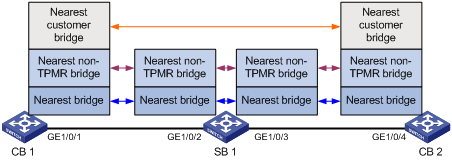
LLDP exchanges packets between neighbor agents and creates and maintains neighbor information for them. Figure 1 shows the neighbor relationships for these LLDP agents. LLDP has two bridge modes: customer bridge (CB) and service bridge (SB).
Figure 1 LLDP neighbor relationships
LLDP frame formats
LLDP sends device information in LLDP frames. LLDP frames are encapsulated in Ethernet II or Subnetwork Access Protocol (SNAP) frames.
· LLDP frame encapsulated in Ethernet II
Figure 2 Ethernet II-encapsulated LLDP frame
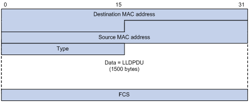
Table 1 Fields in an Ethernet II-encapsulated LLDP frame
|
Field |
Description |
|
Destination MAC address |
MAC address to which the LLDP frame is advertised. LLDP specifies different multicast MAC addresses as destination MAC addresses for LLDP frames destined for agents of different types. This helps distinguish between LLDP frames sent and received by different agent types on the same interface. The destination MAC address is fixed to one of the following multicast MAC addresses: · 0x0180-c200-000E for LLDP frames destined for nearest bridge agents. · 0x0180-c200-0000 for LLDP frames destined for nearest customer bridge agents. · 0x0180-c200-0003 for LLDP frames destined for nearest non-TPMR bridge agents. |
|
Source MAC address |
MAC address of the sending port. |
|
Type |
Ethernet type for the upper-layer protocol. This field is 0x88CC for LLDP. |
|
Data |
LLDPDU. |
|
FCS |
Frame check sequence, a 32-bit CRC value used to determine the validity of the received Ethernet frame. |
· LLDP frame encapsulated in SNAP
Figure 3 SNAP-encapsulated LLDP frame
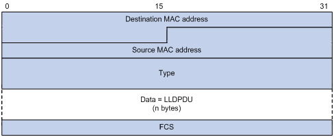
Table 2 Fields in a SNAP-encapsulated LLDP frame
|
Field |
Description |
|
Destination MAC address |
MAC address to which the LLDP frame is advertised. It is the same as that for Ethernet II-encapsulated LLDP frames. |
|
Source MAC address |
MAC address of the sending port. |
|
Type |
SNAP type for the upper-layer protocol. This field is 0xAAAA-0300-0000-88CC for LLDP. |
|
Data |
LLDPDU. |
|
FCS |
Frame check sequence, a 32-bit CRC value used to determine the validity of the received Ethernet frame. |
LLDPDUs
LLDP uses LLDPDUs to exchange information. An LLDPDU comprises multiple TLVs. Each TLV carries a type of device information, as shown in Figure 4.
Figure 4 LLDPDU encapsulation format
![]()
An LLDPDU can carry up to 32 types of TLVs. Mandatory TLVs include Chassis ID TLV, Port ID TLV, and Time to Live TLV. Other TLVs are optional.
TLVs
A TLV is an information element that contains the type, length, and value fields.
LLDPDU TLVs include the following categories:
· Basic management TLVs
· Organizationally (IEEE 802.1 and IEEE 802.3) specific TLVs
· LLDP-MED (media endpoint discovery) TLVs
Basic management TLVs are essential to device management.
Organizationally specific TLVs and LLDP-MED TLVs are used for enhanced device management. They are defined by standardization or other organizations and are optional for LLDPDUs.
· Basic management TLVs
Table 3 lists the basic management TLV types. Some of them are mandatory for LLDPDUs.
|
Type |
Description |
Remarks |
|
Chassis ID |
Specifies the bridge MAC address of the sending device. |
Mandatory. |
|
Port ID |
Specifies the ID of the sending port: · If the LLDPDU carries LLDP-MED TLVs, the port ID TLV carries the MAC address of the sending port. · Otherwise, the port ID TLV carries the port name. |
|
|
Time to Live |
Specifies the life of the transmitted information on the receiving device. |
|
|
End of LLDPDU |
Marks the end of the TLV sequence in the LLDPDU. |
Optional. |
|
Port Description |
Specifies the description for the sending port. |
|
|
System Name |
Specifies the assigned name of the sending device. |
|
|
System Description |
Specifies the description for the sending device. |
|
|
System Capabilities |
Identifies the primary features of the sending device and the enabled primary features. |
|
|
Management Address |
Specifies the following elements: · The management address of the local device. · The interface number and object identifier (OID) associated with the address. |
· IEEE 802.1 organizationally specific TLVs
Table 4 IEEE 802.1 organizationally specific TLVs
|
Type |
Description |
|
Port VLAN ID (PVID) |
Specifies the port VLAN identifier. |
|
Port And Protocol VLAN ID (PPVID) |
Indicates whether the device supports protocol VLANs and, if so, what VLAN IDs these protocols will be associated with. |
|
VLAN Name |
Specifies the textual name of any VLAN to which the port belongs. |
|
Protocol Identity |
Indicates protocols supported on the port. |
|
DCBX |
Data center bridging exchange protocol. |
|
EVB module |
Edge Virtual Bridging module, including EVB TLV and CDCP TLV. For more information, see EVB Configuration Guide. |
|
Link Aggregation |
Indicates whether the port supports link aggregation, and if yes, whether link aggregation is enabled. |
|
Management VID |
Management VLAN ID. |
|
VID Usage Digest |
VLAN ID usage digest. |
|
ETS Configuration |
Enhanced Transmission Selection configuration. |
|
ETS Recommendation |
ETS recommendation. |
|
PFC |
Priority-based Flow Control. |
|
APP |
Application protocol. |
|
QCN |
Quantized Congestion Notification. The QCN TLV is not supported in the current software version. |
|
|
NOTE: · H3C devices support only receiving protocol identity TLVs and VID usage digest TLVs. · Layer 3 Ethernet ports support only link aggregation TLVs. |
· IEEE 802.3 organizationally specific TLVs
Table 5 IEEE 802.3 organizationally specific TLVs
|
Type |
Description |
|
MAC/PHY Configuration/Status |
Contains the bit-rate and duplex capabilities of the port, support for autonegotiation, enabling status of autonegotiation, and the current rate and duplex mode. |
|
Power Via MDI |
Contains the power supply capabilities of the port: · Port class (PSE or PD). · Power supply mode. · Whether PSE power supply is supported. · Whether PSE power supply is enabled. · Whether pair selection can be controlled. · Power supply type. · Power source. · Power priority. · PD requested power. · PSE allocated power. |
|
Maximum Frame Size |
Indicates the supported maximum frame size. It is now the MTU of the port. |
|
Power Stateful Control |
Indicates the power state control configured on the sending port, including the following: · Power supply mode of the PSE/PD. · PSE/PD priority. · PSE/PD power. |
|
Energy-Efficient Ethernet |
Indicates Energy Efficient Ethernet (EEE). |
|
|
NOTE: The Power Stateful Control TLV is defined in IEEE P802.3at D1.0 and is not supported in later versions. H3C devices send this type of TLVs only after receiving them. |
· LLDP-MED TLVs
LLDP-MED TLVs provide multiple advanced applications for voice over IP (VoIP), such as basic configuration, network policy configuration, and address and directory management. LLDP-MED TLVs provide a cost-effective and easy-to-use solution for deploying voice devices in Ethernet. LLDP-MED TLVs are shown in Table 6.
|
Type |
Description |
|
LLDP-MED Capabilities |
Allows a network device to advertise the LLDP-MED TLVs that it supports. |
|
Network Policy |
Allows a network device or terminal device to advertise the VLAN ID of a port, the VLAN type, and the Layer 2 and Layer 3 priorities for specific applications. |
|
Extended Power-via-MDI |
Allows a network device or terminal device to advertise power supply capability. This TLV is an extension of the Power Via MDI TLV. |
|
Hardware Revision |
Allows a terminal device to advertise its hardware version. |
|
Firmware Revision |
Allows a terminal device to advertise its firmware version. |
|
Software Revision |
Allows a terminal device to advertise its software version. |
|
Serial Number |
Allows a terminal device to advertise its serial number. |
|
Manufacturer Name |
Allows a terminal device to advertise its vendor name. |
|
Model Name |
Allows a terminal device to advertise its model name. |
|
Asset ID |
Allows a terminal device to advertise its asset ID. The typical case is that the user specifies the asset ID for the endpoint to facilitate directory management and asset tracking. |
|
Location Identification |
Allows a network device to advertise the appropriate location identifier information for a terminal device to use in the context of location-based applications. |
|
|
NOTE: · If the MAC/PHY configuration/status TLV is not advertisable, none of the LLDP-MED TLVs will be advertised even if they are advertisable. · If the LLDP-MED capabilities TLV is not advertisable, the other LLDP-MED TLVs will not be advertised even if they are advertisable. |
Management address
The network management system uses the management address of a device to identify and manage the device for topology maintenance and network management. The management address is encapsulated in the management address TLV.
Working mechanism
LLDP operating modes
An LLDP agent can operate in one of the following modes:
· TxRx mode—An LLDP agent in this mode can send and receive LLDP frames.
· Tx mode—An LLDP agent in this mode can only send LLDP frames.
· Rx mode—An LLDP agent in this mode can only receive LLDP frames.
· Disable mode—An LLDP agent in this mode cannot send or receive LLDP frames.
Each time the LLDP operating mode of an LLDP agent changes, its LLDP protocol state machine reinitializes. A configurable reinitialization delay prevents frequent initializations caused by frequent changes to the operating mode. If you configure the reinitialization delay, an LLDP agent must wait the specified amount of time to initialize LLDP after the LLDP operating mode changes.
Transmitting LLDP frames
An LLDP agent operating in TxRx mode or Tx mode sends LLDP frames to its directly connected devices both periodically and when the local configuration changes. To prevent LLDP frames from overwhelming the network during times of frequent changes to local device information, LLDP uses the token bucket mechanism to rate limit LLDP frames. For more information about the token bucket mechanism, see ACL and QoS Configuration Guide.
LLDP automatically enables the fast LLDP frame transmission mechanism in either of the following cases:
· A new LLDP frame is received and carries device information new to the local device.
· The LLDP operating mode of the LLDP agent changes from Disable or Rx to TxRx or Tx.
The fast LLDP frame transmission mechanism successively sends the specified number of LLDP frames at a configurable fast LLDP frame transmission interval. The mechanism helps LLDP neighbors discover the local device as soon as possible. Then, the normal LLDP frame transmission interval resumes.
Receiving LLDP frames
An LLDP agent operating in TxRx mode or Rx mode confirms the validity of TLVs carried in every received LLDP frame. If the TLVs are valid, the LLDP agent saves the information and starts an aging timer. The initial value of the aging timer is equal to the TTL value in the Time To Live TLV carried in the LLDP frame. When the LLDP agent receives a new LLDP frame, the aging timer restarts. When the aging timer decreases to zero, all saved information ages out.
Protocols and standards
· IEEE 802.1AB-2005, Station and Media Access Control Connectivity Discovery
· IEEE 802.1AB-2009, Station and Media Access Control Connectivity Discovery
· ANSI/TIA-1057, Link Layer Discovery Protocol for Media Endpoint Devices
· DCB Capability Exchange Protocol Specification Rev 1.00
· DCB Capability Exchange Protocol Base Specification Rev 1.01
· IEEE Std 802.1Qaz-2011, Media Access Control (MAC) Bridges and Virtual Bridged Local Area Networks-Amendment 18: Enhanced Transmission Selection for Bandwidth Sharing Between Traffic Classes
LLDP configuration task list
|
Tasks at a glance |
|
Performing basic LLDP configurations: · (Required.) Enabling LLDP · (Optional.) Setting the LLDP bridge mode · (Optional.) Setting the LLDP operating mode · (Optional.) Setting the LLDP reinitialization delay · (Optional.) Enabling LLDP polling · (Optional.) Configuring the advertisable TLVs · (Optional.) Configuring the management address and its encoding format · (Optional.) Setting other LLDP parameters · (Optional.) Setting an encapsulation format for LLDP frames · (Optional.) Disabling LLDP PVID inconsistency check |
|
(Optional.) Configuring CDP compatibility |
|
(Optional.) Configuring DCBX |
|
(Optional.) Configuring LLDP trapping and LLDP-MED trapping |
|
(Optional.) Setting the source MAC address of LLDP frames to the MAC address of a Layer 3 Ethernet subinterface |
|
(Optional.) Enabling the device to generate ARP or ND entries for received management address LLDP TLVs |
Performing basic LLDP configurations
Enabling LLDP
To make LLDP take effect on specific ports, you must enable LLDP both globally and on these ports.
To use LLDP together with OpenFlow, you must enable LLDP globally on OpenFlow switches. To prevent LLDP from affecting topology discovery of OpenFlow controllers, disable LLDP on ports of OpenFlow instances. For more information about OpenFlow, see OpenFlow Configuration Guide.
To enable LLDP:
|
Step |
Command |
Remarks |
|
1. Enter system view. |
system-view |
N/A |
|
2. Enable LLDP globally. |
lldp global enable |
By default, LLDP is disabled globally. |
|
3. Enter Layer 2/Layer 3 Ethernet interface view, management Ethernet interface view, Layer 2/Layer 3 aggregate interface view, or IRF physical interface view. |
interface interface-type interface-number |
N/A |
|
4. Enable LLDP. |
lldp enable |
By default, LLDP is enabled on a port. |
|
|
NOTE: An LLDP-enabled IRF physical interface supports only the nearest bridge agents. |
Setting the LLDP bridge mode
The following LLDP bridge modes are available:
· Customer bridge mode—LLDP supports nearest bridge agents, nearest non-TPMR bridge agents, and nearest customer bridge agents. LLDP processes the LLDP frames with destination MAC addresses for these agents and transparently transmits the LLDP frames with other destination MAC addresses in the VLAN.
· Service bridge mode—LLDP supports nearest bridge agents and nearest non-TPMR bridge agents. LLDP processes the LLDP frames with destination MAC addresses for these agents and transparently transmits the LLDP frames with other destination MAC addresses in the VLAN.
To set the LLDP bridge mode:
|
Step |
Command |
Remarks |
|
1. Enter system view. |
system-view |
N/A |
|
2. Set the LLDP bridge mode to service bridge. |
lldp mode service-bridge |
By default, LLDP operates in customer bridge mode. |
Setting the LLDP operating mode
|
Step |
Command |
Remarks |
|
1. Enter system view. |
system-view |
N/A |
|
2. Enter Layer 2/Layer 3 Ethernet interface view, management Ethernet interface view, Layer 2/Layer 3 aggregate interface view, or IRF physical interface view. |
interface interface-type interface-number |
N/A |
|
3. Set the LLDP operating mode. |
· In Layer 2/Layer 3 Ethernet interface
view or management Ethernet interface view: · In Layer 2/Layer 3 aggregate interface view: · In IRF physical interface view: |
By default: · The nearest bridge agent operates in txrx mode. · The nearest customer bridge agent and nearest non-TPMR bridge agent operate in disable mode. In Ethernet interface view, if you do not specify an agent type, the command sets the operating mode for nearest bridge agents. In aggregate interface view, you can set the operating mode only for nearest customer bridge agents and nearest non-TPMR bridge agents. In IRF physical interface view, you can set the operating mode only for nearest bridge agents. |
Setting the LLDP reinitialization delay
When the LLDP operating mode changes on a port, the port initializes the protocol state machines after an LLDP reinitialization delay. By adjusting the delay, you can avoid frequent initializations caused by frequent changes to the LLDP operating mode on a port.
To set the LLDP reinitialization delay for ports:
|
Step |
Command |
Remarks |
|
1. Enter system view. |
system-view |
N/A |
|
2. Set the LLDP reinitialization delay. |
lldp timer reinit-delay delay |
The default setting is 2 seconds. |
Enabling LLDP polling
With LLDP polling enabled, a device periodically searches for local configuration changes. When the device detects a configuration change, it sends LLDP frames to inform neighboring devices of the change.
To enable LLDP polling:
|
Step |
Command |
Remarks |
|
1. Enter system view. |
system-view |
N/A |
|
2. Enter Layer 2/Layer 3 Ethernet interface view, management Ethernet interface view, Layer 2/Layer 3 aggregate interface view, or IRF physical interface view. |
interface interface-type interface-number |
N/A |
|
3. Enable LLDP polling and set the polling interval. |
· In Layer 2/Layer 3 Ethernet interface
view or management Ethernet interface view: · In Layer 2/Layer 3 aggregate interface view: · In IRF physical interface view: |
By default, LLDP polling is disabled. |
Configuring the advertisable TLVs
|
Step |
Command |
Remarks |
|
1. Enter system view. |
system-view |
N/A |
|
2. Enter Layer 2/Layer 3 Ethernet interface view, management Ethernet interface view, Layer 2/Layer 3 aggregate interface view, or IRF physical interface view. |
interface interface-type interface-number |
N/A |
|
3. Configure the advertisable TLVs (in Layer 2 Ethernet interface view). |
· lldp tlv-enable { basic-tlv { all | port-description | system-capability | system-description | system-name | management-address-tlv [ ipv6 ] [ ip-address ] } | dot1-tlv { all | port-vlan-id | link-aggregation | dcbx | protocol-vlan-id [ vlan-id ] | vlan-name [ vlan-id ] | management-vid [ mvlan-id ] } | dot3-tlv { all | mac-physic | max-frame-size | power } | med-tlv { all | capability | inventory | network-policy [ vlan-id ] | power-over-ethernet | location-id { civic-address device-type country-code { ca-type ca-value }&<1-10> | elin-address tel-number } } } · lldp agent nearest-nontpmr tlv-enable { basic-tlv { all | port-description | system-capability | system-description | system-name | management-address-tlv [ ipv6 ] [ ip-address ] } | dot1-tlv { all | evb | port-vlan-id | link-aggregation } } · lldp agent nearest-customer tlv-enable { basic-tlv { all | port-description | system-capability | system-description | system-name | management-address-tlv [ ipv6 ] [ ip-address ] } | dot1-tlv { all | port-vlan-id | link-aggregation } } |
By default: · Nearest bridge agents can advertise all LLDP TLVs except the DCBX, location identification, port and protocol VLAN ID, VLAN name, management VLAN ID, and EVB TLVs. · Nearest non-TPMR bridge agents can advertise only EVB TLVs. Nearest customer bridge agents can advertise all basic TLVs as well as port VLAN ID and link aggregation 802.1 organizationally specific TLVs. |
|
4. Configure the advertisable TLVs (in Layer 3 Ethernet interface view). |
· lldp tlv-enable { basic-tlv { all | port-description | system-capability | system-description | system-name | management-address-tlv [ ipv6 ] [ ip-address | interface loopback interface-number ] } | dot1-tlv { all | link-aggregation } | dot3-tlv { all | mac-physic | max-frame-size | power } | med-tlv { all | capability | inventory | power-over-ethernet | location-id { civic-address device-type country-code { ca-type ca-value }&<1-10> | elin-address tel-number } } } · lldp agent { nearest-nontpmr | nearest-customer } tlv-enable { basic-tlv { all | port-description | system-capability | system-description | system-name | management-address-tlv [ ipv6 ] [ ip-address ] } | dot1-tlv { all | link-aggregation } } |
By default: · Nearest bridge agents can advertise all types of LLDP TLVs (only link aggregation TLV is supported in 802.1 organizationally specific TLVs) except network policy and location identification TLVs. · Nearest non-TPMR bridge agents do not advertise TLVs. · Nearest customer bridge agents can advertise all basic TLVs and the link aggregation 802.1 organizationally specific TLV. |
|
5. Configure the advertisable TLVs (in management Ethernet interface view). |
· lldp tlv-enable { basic-tlv { all | port-description | system-capability | system-description | system-name | management-address-tlv [ ipv6 ] [ ip-address ] } | dot1-tlv { all | link-aggregation } | dot3-tlv { all | mac-physic | max-frame-size | power } | med-tlv { all | capability | inventory | power-over-ethernet | location-id { civic-address device-type country-code { ca-type ca-value }&<1-10> | elin-address tel-number } } } · lldp agent { nearest-nontpmr | nearest-customer } tlv-enable { basic-tlv { all | port-description | system-capability | system-description | system-name | management-address-tlv [ ipv6 ] [ ip-address ] } | dot1-tlv { all | link-aggregation } } |
By default: · Nearest bridge agents can advertise all types of LLDP TLVs (only link aggregation TLV is supported in 802.1 organizationally specific TLVs) except network policy and location identification TLVs. · Nearest non-TPMR bridge agents do not advertise TLVs. · Nearest customer bridge agents can advertise basic TLVs and IEEE 802.1 organizationally specific TLVs (only the link aggregation TLV is supported). |
|
6. Configure the advertisable TLVs (in Layer 2 aggregate interface view). |
· lldp agent nearest-nontpmr tlv-enable { basic-tlv { all | management-address-tlv [ ipv6 ] [ ip-address ] | port-description | system-capability | system-description | system-name } | dot1-tlv { all | evb | port-vlan-id } } · lldp agent nearest-customer tlv-enable { basic-tlv { all | management-address-tlv [ ipv6 ] [ ip-address ] | port-description | system-capability | system-description | system-name } | dot1-tlv { all | port-vlan-id } } · lldp tlv-enable dot1-tlv { protocol-vlan-id [ vlan-id ] | vlan-name [ vlan-id ] | management-vid [ mvlan-id ] } |
By default: · Nearest non-TPMR bridge agents can advertise only EVB TLVs. · Nearest customer bridge agents can advertise basic TLVs and IEEE 802.1 organizationally specific TLVs (only the port VLAN ID TLV is supported). Nearest bridge agents are not supported on Layer 2 aggregate interfaces. |
|
7. Configure the advertisable TLVs (in Layer 3 aggregate interface view). |
lldp agent { nearest-nontpmr | nearest-customer } tlv-enable basic-tlv { all | management-address-tlv [ ipv6 ] [ ip-address ] | port-description | system-capability | system-description | system-name } |
By default: · Nearest non-TPMR bridge agents do not advertise TLVs. · Nearest customer bridge agents can advertise only basic TLVs. Nearest bridge agents are not supported on Layer 3 aggregate interfaces. |
|
8. Configure the advertisable TLVs (in IRF physical interface view). |
lldp tlv-enable basic-tlv { port-description | system-capability | system-description | system-name } |
An LLDP-enabled IRF physical interface supports only the nearest bridge agent. By default, nearest bridge agents can advertise all types of LLDP TLVs. |
Configuring the management address and its encoding format
LLDP encodes management addresses in numeric or string format in management address TLVs.
If a neighbor encodes its management address in string format, set the encoding format of the management address to string on the connecting port. This guarantees normal communication with the neighbor.
To configure a management address to be advertised and its encoding format on a port:
|
Step |
Command |
Remarks |
|
1. Enter system view. |
system-view |
N/A |
|
2. Enter Layer 2/Layer 3 Ethernet interface view, management Ethernet interface view, or Layer 2/Layer 3 aggregate interface view. |
interface interface-type interface-number |
N/A |
|
3. Allow LLDP to advertise the management address in LLDP frames and configure the advertised management address. |
· In Layer 2 Ethernet interface view or
management Ethernet interface view: · In Layer 3 Ethernet interface view: · In Layer 2/Layer 3 aggregate interface view: |
By default: · Nearest bridge agents and nearest customer bridge agents can advertise the management address in LLDP frames. · Nearest non-TPMR bridge agents cannot advertise the management address in LLDP frames. |
|
4. Set the encoding format of the management address to string. |
· In Layer 2/Layer 3 Ethernet interface
view or management Ethernet interface view: · In Layer 2/Layer 3 aggregate interface
view: |
By default, the encoding format of the management address is numeric. The device supports only the numeric encoding format for IPv6 management addresses. |
Setting other LLDP parameters
The Time to Live TLV carried in an LLDPDU determines how long the device information carried in the LLDPDU can be saved on a recipient device.
By setting the TTL multiplier, you can configure the TTL of locally sent LLDPDUs. The TTL is expressed by using the following formula:
TTL = Min (65535, (TTL multiplier × LLDP frame transmission interval + 1))
As the expression shows, the TTL can be up to 65535 seconds. TTLs greater than 65535 will be rounded down to 65535 seconds.
To set LLDP parameters:
|
Step |
Command |
Remarks |
|
1. Enter system view. |
system-view |
N/A |
|
2. Set the TTL multiplier. |
lldp hold-multiplier value |
The default setting is 4. |
|
3. Set the LLDP frame transmission interval. |
lldp timer tx-interval interval |
The default setting is 30 seconds. |
|
4. Set the token bucket size for sending LLDP frames. |
lldp max-credit credit-value |
The default setting is 5. |
|
5. Set the number of LLDP frames sent each time fast LLDP frame transmission is triggered. |
lldp fast-count count |
The default setting is 4. |
|
6. Set the fast LLDP frame transmission interval. |
lldp timer fast-interval interval |
The default setting is 1 second. |
Setting an encapsulation format for LLDP frames
LLDP frames can be encapsulated in the following formats:
· Ethernet II—With Ethernet II encapsulation configured, an LLDP port sends LLDP frames in Ethernet II frames.
· SNAP—With SNAP encapsulation configured, an LLDP port sends LLDP frames in SNAP frames.
Earlier versions of LLDP require the same encapsulation format on both ends to process LLDP frames. To successfully communicate with a neighboring device running an earlier version of LLDP, the local device must be set with the same encapsulation format.
To set the encapsulation format for LLDP frames to SNAP:
|
Step |
Command |
Remarks |
|
1. Enter system view. |
system-view |
N/A |
|
2. Enter Layer 2/Layer 3 Ethernet interface view, management Ethernet interface view, Layer 2/Layer 3 aggregate interface view, or IRF physical interface view. |
interface interface-type interface-number |
N/A |
|
3. Set the encapsulation format for LLDP frames to SNAP. |
· In Layer 2/Layer 3 Ethernet interface
view or management Ethernet interface view: · In Layer 2/Layer 3 aggregate interface view: · In IRF physical interface view: |
By default, Ethernet II encapsulation format applies. |
Disabling LLDP PVID inconsistency check
By default, when the system receives an LLDP packet, it compares the PVID value contained in packet with the PVID configured on the receiving interface. If the two PVIDs do not match, a log message will be printed to notify the user.
You can disable PVID inconsistency check if different PVIDs are required on a link.
To disable LLDP PVID inconsistency check:
|
Step |
Command |
Remarks |
|
1. Enter system view. |
system-view |
N/A |
|
2. Disable LLDP PVID inconsistency check. |
lldp ignore-pvid-inconsistency |
By default, LLDP PVID inconsistency check is enabled. |
Configuring CDP compatibility
To enable your device to exchange information with a directly connected Cisco device that supports only CDP, you must enable CDP compatibility.
CDP compatibility enables your device to receive and recognize CDP packets from the neighboring CDP device and send CDP packets to the neighboring device. The CDP packets sent to the neighboring CDP device carry the following information:
· Device ID.
· ID of the port connecting to the neighboring device.
· Port IP address.
· TTL.
The port IP address is the primary IP address of a VLAN interface in up state. The VLAN ID of the VLAN interface must be the lowest among the VLANs permitted on the port. If no VLAN interfaces of the permitted VLANs are assigned an IP address or all VLAN interfaces are down, no port IP address will be advertised.
You can view the neighboring CDP device information that can be recognized by the device in the output of the display lldp neighbor-information command. For more information about the display lldp neighbor-information command, see Layer 2—LAN Switching Command Reference.
To make your device work with Cisco IP phones, you must enable CDP compatibility.
If your LLDP-enabled device cannot recognize CDP packets, it does not respond to the requests of Cisco IP phones for the voice VLAN ID configured on the device. As a result, a requesting Cisco IP phone sends voice traffic without any tag to your device. Your device cannot differentiate the voice traffic from other types of traffic.
For more information about voice VLANs, see "Configuring voice VLANs."
Configuration prerequisites
Before you configure CDP compatibility, complete the following tasks:
· Globally enable LLDP.
· Enable LLDP on the port connecting to a CDP device.
· Configure LLDP to operate in TxRx mode on the port.
Configuration procedure
CDP-compatible LLDP operates in one of the following modes:
· TxRx—CDP packets can be transmitted and received.
· Rx—CDP packets can be received but cannot be transmitted.
· Disable—CDP packets cannot be transmitted or received.
To make CDP-compatible LLDP take effect on a port, follow these steps:
1. Enable CDP-compatible LLDP globally.
2. Configure CDP-compatible LLDP to operate in TxRx mode on the port.
The maximum TTL value that CDP allows is 255 seconds. To make CDP-compatible LLDP work correctly with CDP devices, configure the LLDP frame transmission interval to be no more than 1/3 of the TTL value.
To configure LLDP to be compatible with CDP:
|
Step |
Command |
Remarks |
|
1. Enter system view. |
system-view |
N/A |
|
2. Enable CDP compatibility globally. |
lldp compliance cdp |
By default, CDP compatibility is disabled globally. |
|
3. Enter Layer 2/Layer 3 Ethernet interface view, management Ethernet interface view, or Layer 2/Layer 3 aggregate interface view. |
interface interface-type interface-number |
N/A |
|
4. Configure CDP-compatible LLDP to operate in TxRx mode. |
lldp compliance admin-status cdp txrx |
By default, CDP-compatible LLDP operates in disable mode. |
|
5. Set the voice VLAN ID carried in CDP packets. |
cdp voice-vlan vlan-id |
By default, no voice VLAN ID is configured to be carried in CDP packets. |
Configuring DCBX
Data Center Ethernet (DCE), also known as Converged Enhanced Ethernet (CEE), is enhancement and expansion of traditional Ethernet local area networks for use in data centers. DCE uses the Data Center Bridging Exchange Protocol (DCBX) to negotiate and remotely configure the bridge capability of network elements.
DCBX has the following self-adaptable versions:
· DCB Capability Exchange Protocol Specification Rev 1.00.
· DCB Capability Exchange Protocol Base Specification Rev 1.01.
· IEEE Std 802.1Qaz-2011 (Media Access Control (MAC) Bridges and Virtual Bridged Local Area Networks-Amendment 18: Enhanced Transmission Selection for Bandwidth Sharing Between Traffic Classes).
DCBX offers the following functions:
· Discovers the peer devices' capabilities and determines whether devices at both ends support these capabilities.
· Detects configuration errors on peer devices.
· Remotely configures the peer device if the peer device accepts the configuration.
|
|
NOTE: H3C devices support only the remote configuration feature. |
Figure 5 DCBX application scenario
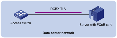
DCBX enables lossless packet transmission on DCE networks.
As shown in Figure 5, DCBX applies to an FCoE-based data center network, and operates on an access switch. DCBX enables the switch to control the server or storage adapter, and simplifies the configuration and guarantees configuration consistency. DCBX extends LLDP by using the IEEE 802.1 organizationally specific TLVs (DCBX TLVs) to transmit DCBX data, including:
· In DCBX Rev 1.00 and DCBX Rev 1.01:
¡ Application Protocol (APP).
¡ Enhanced Transmission Selection (ETS).
¡ Priority-based Flow Control (PFC).
· In IEEE Std 802.1Qaz-2011:
¡ ETS Configuration.
¡ ETS Recommendation.
¡ PFC.
¡ APP.
DCBX configuration task list
|
Tasks at a glance |
|
|
(Required.) Enabling LLDP and DCBX TLV advertising |
|
|
(Required.) Setting the DCBX version |
|
|
(Required.) Configuring APP parameters |
|
|
(Required.) Configuring ETS parameters: |
|
|
(Required.) Configuring PFC parameters |
|
Enabling LLDP and DCBX TLV advertising
To enable the device to advertise APP, ETS, and PFC data through an interface, perform the following tasks:
· Enable LLDP globally.
· Enable LLDP and DCBX TLV advertising on the interface.
To enable LLDP and DCBX TLV advertising:
|
Step |
Command |
Remarks |
|
1. Enter system view. |
system-view |
N/A |
|
2. Enable LLDP globally. |
lldp global enable |
By default, LLDP is disabled globally. |
|
3. Enter Layer 2 Ethernet interface view. |
interface interface-type interface-number |
N/A |
|
4. Enable LLDP. |
lldp enable |
By default, LLDP is enabled on an interface. |
|
5. Enable the interface to advertise DCBX TLVs. |
lldp tlv-enable dot1-tlv dcbx |
By default, DCBX TLV advertising is disabled on an interface. |
Setting the DCBX version
When you set the DCBX version, follow these restrictions and guidelines:
· For DCBX to work correctly, configure the same DCBX version on the local port and peer port. As a best practice, configure the highest version supported on both ends. IEEE Std 802.1Qaz-2011, DCBX Rev 1.01, and DCBX Rev 1.00 are in descending order.
· After the configuration, LLDP frames sent by the local port carry information about the configured DCBX version. The local port and peer port do not negotiate the DCBX version.
· When the DCBX version is autonegotiated, the version IEEE Std 802.1Qaz-2011 is preferably negotiated.
To set the DCBX version:
|
Step |
Command |
Remarks |
|
1. Enter system view. |
system-view |
N/A |
|
2. Enter Layer 2 Ethernet interface view. |
interface interface-type interface-number |
N/A |
|
3. Set the DCBX version. |
dcbx version { rev100 | rev101 | standard } |
By default, the DCBX version is not configured. It is autonegotiated by the local port and peer port. |
Configuring APP parameters
The device negotiates with the server adapter by using the APP parameters to achieve the following purposes:
· Control the 802.1p priority values of the protocol packets that the server adapter sends.
· Identify traffic based on the 802.1p priority values.
For example, the device can use the APP parameters to negotiate with the server adapter to set 802.1p priority 3 for all FCoE and FIP frames. When the negotiation succeeds, all FCoE and FIP frames that the server adapter sends to the device carry the 802.1p priority 3.
Configuration restrictions and guidelines
When you configure APP parameters, follow these restrictions and guidelines:
· An Ethernet frame header ACL identifies application protocol packets by frame type.
· An IPv4 advanced ACL identifies application protocol packets by TCP/UDP port number.
· DCBX Rev 1.00 identifies application protocol packets only by frame type and advertises only TLVs with frame type 0x8906 (FCoE).
· DCBX Rev 1.01 has the following attributes:
¡ Supports identifying application protocol packets by both frame type and TCP/UDP port number.
¡ Does not restrict the frame type or TCP/UDP port number for advertising TLVs.
¡ Can advertise up to 77 TLVs according to the remaining length of the current packet.
· In a QoS policy, you can configure multiple class-behavior associations. A packet might be configured with multiple 802.1p priority marking or mapping actions, and the one configured first takes effect.
Configuration procedure
To configure APP parameters:
|
Step |
Command |
Remarks |
|
1. Enter system view. |
system-view |
N/A |
|
2. Create an ACL and enter ACL view. |
· Create an Ethernet frame header ACL and enter
ACL view: · Create an IPv4 advanced ACL and enter ACL
view: |
An Ethernet frame header ACL number is in the range of 4000 to 4999. An IPv4 advanced ACL number is in the range of 3000 to 3999. DCBX Rev 1.00 supports only Ethernet frame header ACLs. DCBX Rev 1.01 and IEEE Std 802.1Qaz-2011 support both Ethernet frame header ACLs and IPv4 advanced ACLs. |
|
3. Create a rule for the ACL. |
· For the Ethernet frame header ACL: · For the IPv4 advanced ACL: |
Create rules according to the type of the ACL previously created. |
|
4. Return to system view. |
quit |
N/A |
|
5. Create a class, specify the operator of the class as OR, and enter class view. |
traffic classifier classifier-name operator or |
N/A |
|
6. Use the specified ACL as the match criterion of the class. |
if-match acl acl-number |
N/A |
|
7. Return to system view. |
quit |
N/A |
|
8. Create a traffic behavior and enter traffic behavior view. |
traffic behavior behavior-name |
N/A |
|
9. Configure the behavior to mark packets with an 802.1p priority. |
remark dot1p 8021p |
N/A |
|
10. Return to system view. |
quit |
N/A |
|
11. Create a QoS policy and enter QoS policy view. |
qos policy policy-name |
N/A |
|
12. Associate the class with the traffic behavior in the QoS policy, and apply the association to DCBX. |
classifier classifier-name behavior behavior-name mode dcbx |
N/A |
|
13. Return to system view. |
quit |
N/A |
|
14. Apply the QoS policy. |
· To the outgoing traffic of all ports: · To the outgoing traffic of a Layer 2 Ethernet interface: a. Enter Layer 2 Ethernet interface view: b. Apply the QoS policy to the outgoing traffic: |
N/A |
For more information about the acl, rule, traffic classifier, if-match, traffic behavior, remark dot1p, qos policy, classifier behavior, qos apply policy global, and qos apply policy commands, see ACL and QoS Command Reference.
Configuring ETS parameters
ETS provides committed bandwidth. To avoid packet loss caused by congestion, the device performs the following operations:
· Uses ETS parameters to negotiate with the server adapter.
· Controls the server adapter's transmission speed of the specified type of traffic.
· Guarantees that the transmission speed is within the committed bandwidth of the interface.
To configure ETS parameters, you must configure the 802.1p-to-local priority mapping and group-based WRR queuing.
Configuring the 802.1p-to-local priority mapping
You can configure the 802.1p-to-local priority mapping either in the MQC method or in the priority mapping table method. If you configure the 802.1p-to-local priority mapping in both methods, the configuration made in the MQC method applies.
To configure the 802.1p-to-local priority mapping in the MQC method:
|
Step |
Command |
Remarks |
|
1. Enter system view. |
system-view |
N/A |
|
2. Create a traffic class, specify the operator of the class as OR, and enter class view. |
traffic classifier classifier-name operator or |
By default, no traffic class exists. |
|
3. Configure the class to match packets with the specified service provider network 802.1p priority values. |
if-match service-dot1p 8021p-list |
By default, no match criterion is configured for the class to match packets. |
|
4. Return to system view. |
quit |
N/A |
|
5. Create a traffic behavior and enter traffic behavior view. |
traffic behavior behavior-name |
By default, no traffic behavior exists. |
|
6. Configure the behavior to mark packets with the specified local precedence value. |
remark local-precedence local-precedence |
By default, no local precedence marking action is configured. |
|
7. Return to system view. |
quit |
N/A |
|
8. Create a QoS policy and enter QoS policy view. |
qos policy policy-name |
By default, no policy exists. |
|
9. Associate the class with the traffic behavior in the QoS policy, and apply the association to DCBX. |
classifier classifier-name behavior behavior-name mode dcbx |
By default, no class-behavior association exists. |
For more information about the traffic classifier, if-match, traffic behavior, remark local-precedence, qos policy, and classifier behavior commands, see ACL and QoS Command Reference.
To configure the 802.1p priority mapping in the priority mapping table method:
|
Step |
Command |
Remarks |
|
1. Enter system view. |
system-view |
N/A |
|
2. Enter 802.1p-to-local priority mapping table view. |
qos map-table dot1p-lp |
N/A |
|
3. Configure the priority mapping table to map the specified 802.1p priority values to a local precedence value. |
import import-value-list export export-value |
For information about the default priority mapping tables, see ACL and QoS Configuration Guide. |
For more information about the qos map-table, qos map-table color, and import commands, see ACL and QoS Command Reference.
Configuring group-based WRR queuing
You can configure group-based WRR queuing to allocate bandwidth.
To configure group-based WRR queuing:
|
Step |
Command |
Remarks |
|
1. Enter system view. |
system-view |
N/A |
|
2. Enter Layer 2 Ethernet interface view. |
interface interface-type interface-number |
N/A |
|
3. Enable WRR queuing. |
qos wrr byte-count |
By default, a Layer 2 Ethernet interface uses the SP queue scheduling mechanism. |
|
4. Configure a queue. |
· Add a queue to WRR priority group 1 and
configure the scheduling weight for the queue: · Configure a queue to use SP queuing: |
Use one or both commands. |
For more information about the qos wrr, qos wrr byte-count, and qos wrr group sp commands, see ACL and QoS Command Reference.
Configuring PFC parameters
To prevent packets with an 802.1p priority value from being dropped, enable PFC for the 802.1p priority value. This feature reduces the sending rate of packets carrying this priority when network congestion occurs.
The device uses PFC parameters to negotiate with the server adapter and to enable PFC for the specified 802.1p priorities on the server adapter.
To configure PFC parameters:
|
Step |
Command |
Remarks |
|
1. Enter system view. |
system-view |
N/A |
|
2. Enter Layer 2 Ethernet interface view. |
interface interface-type interface-number |
N/A |
|
3. Enable PFC in auto mode on the Ethernet interface. |
priority-flow-control auto |
By default, PFC is disabled. To advertise the PFC data, you must enable PFC in auto mode. |
|
4. Enable PFC for the specified 802.1p priorities. |
priority-flow-control no-drop dot1p dot1p-list |
By default, PFC is disabled for all 802.1p priorities. |
For more information about the priority-flow-control and priority-flow-control no-drop dot1p commands, see Interface Command Reference.
Configuring LLDP trapping and LLDP-MED trapping
LLDP trapping or LLDP-MED trapping notifies the network management system of events such as newly detected neighboring devices and link failures.
To prevent excessive LLDP traps from being sent when the topology is unstable, set a trap transmission interval for LLDP.
To configure LLDP trapping and LLDP-MED trapping:
|
Step |
Command |
Remarks |
|
1. Enter system view. |
system-view |
N/A |
|
2. Enter Layer 2/Layer 3 Ethernet interface view, management Ethernet interface view, Layer 2/Layer 3 aggregate interface view, or IRF physical interface view. |
interface interface-type interface-number |
N/A |
|
3. Enable LLDP trapping. |
· In Layer 2/Layer 3 Ethernet interface
view or management Ethernet interface view: · In Layer 2/Layer 3 aggregate interface
view: · In IRF physical interface view: |
By default, LLDP trapping is disabled. |
|
4. Enable LLDP-MED trapping (in Layer 2/Layer 3 Ethernet interface view or management Ethernet interface view). |
lldp notification med-topology-change enable |
By default, LLDP-MED trapping is disabled. |
|
5. Return to system view. |
quit |
N/A |
|
6. (Optional.) Set the LLDP trap transmission interval. |
lldp timer notification-interval interval |
The default setting is 30 seconds. |
Setting the source MAC address of LLDP frames to the MAC address of a Layer 3 Ethernet subinterface
|
Step |
Command |
Remarks |
|
1. Enter system view. |
system-view |
N/A |
|
2. Enter Layer 3 Ethernet interface view. |
interface interface-type interface-number |
N/A |
|
3. Set the source MAC address of LLDP frames to the MAC address of a Layer 3 Ethernet subinterface. |
lldp source-mac vlan vlan-id |
By default, the source MAC address of LLDP frames is the MAC address of the Layer 3 Ethernet interface. The specified VLAN ID is used as the subnumber element of the Layer 3 Ethernet subinterface number interface-number.subnumber. |
Enabling the device to generate ARP or ND entries for received management address LLDP TLVs
This feature enables the device to generate an ARP or ND entry for a received LLDP frame that carries a management address TLV. The ARP or ND entry contains the management address and the source MAC address of the frame.
You can enable the device to generate both ARP and ND entries. If the management address TLV contains an IPv4 address, the device generates an ARP entry. If the management address TLV contains an IPv6 address, the device generates an ND entry.
To enable the device to generate an ARP or ND entry for a received management address LLDP TLV:
|
Step |
Command |
Remarks |
|
1. Enter system view. |
system-view |
N/A |
|
2. Enter Layer 3 Ethernet interface view. |
interface interface-type interface-number |
N/A |
|
3. Enable the device to generate an ARP or ND entry for a management address LLDP TLV received on the interface. |
lldp management-address { arp-learning | nd-learning } [ vlan vlan-id ] |
By default, the device does not generate an ARP or ND entry when receiving a management address LLDP TLV. Include the vlan vlan-id option to generate the ARP or ND entry for the Layer 3 Ethernet subinterface associated with the specified VLAN ID in Dot1q termination. |
Displaying and maintaining LLDP
Execute display commands in any view.
|
Command |
|
|
Display local LLDP information. |
display lldp local-information [ global | interface interface-type interface-number ] |
|
Display the information contained in the LLDP TLVs sent from neighboring devices. |
display lldp neighbor-information [ [ [ interface interface-type interface-number ] [ agent { nearest-bridge | nearest-customer | nearest-nontpmr } ] [ verbose ] ] | list [ system-name system-name ] ] |
|
Display LLDP statistics. |
display lldp statistics [ global | [ interface interface-type interface-number ] [ agent { nearest-bridge | nearest-customer | nearest-nontpmr } ] ] |
|
Display LLDP status of a port. |
display lldp status [ interface interface-type interface-number ] [ agent { nearest-bridge | nearest-customer | nearest-nontpmr } ] |
|
Display types of advertisable optional LLDP TLVs. |
display lldp tlv-config [ interface interface-type interface-number ] [ agent { nearest-bridge | nearest-customer | nearest-nontpmr } ] |
LLDP configuration examples
Basic LLDP configuration example
Network requirements
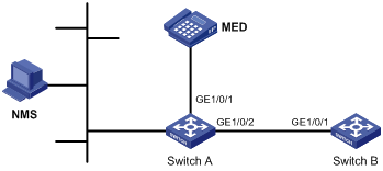
As shown in Figure 6, enable LLDP globally on Switch A and Switch B to perform the following tasks:
· Monitor the link between Switch A and Switch B on the NMS.
· Monitor the link between Switch A and the MED device on the NMS.
Configuration procedure
1. Configure Switch A:
# Enable LLDP globally.
<SwitchA> system-view
[SwitchA] lldp global enable
# Enable LLDP on GigabitEthernet 1/0/1. By default, LLDP is enabled on ports.
[SwitchA] interface gigabitethernet 1/0/1
[SwitchA-GigabitEthernet1/0/1] lldp enable
# Set the LLDP operating mode to Rx on GigabitEthernet 1/0/1.
[SwitchA-GigabitEthernet1/0/1] lldp admin-status rx
[SwitchA-GigabitEthernet1/0/1] quit
# Enable LLDP on GigabitEthernet 1/0/2. By default, LLDP is enabled on ports.
[SwitchA] interface gigabitethernet1/2
[SwitchA-GigabitEthernet1/0/2] lldp enable
# Set the LLDP operating mode to Rx on GigabitEthernet 1/0/2.
[SwitchA-GigabitEthernet1/0/2] lldp admin-status rx
[SwitchA-GigabitEthernet1/0/2] quit
2. Configure Switch B:
# Enable LLDP globally.
<SwitchB> system-view
[SwitchB] lldp global enable
# Enable LLDP on GigabitEthernet 1/0/1. By default, LLDP is enabled on ports.
[SwitchB] interface gigabitethernet 1/0/1
[SwitchB-GigabitEthernet1/0/1] lldp enable
# Set the LLDP operating mode to Tx on GigabitEthernet 1/0/1.
[SwitchB-GigabitEthernet1/0/1] lldp admin-status tx
[SwitchB-GigabitEthernet1/0/1] quit
Verifying the configuration
# Verify the following items:
· GigabitEthernet 1/0/1 of Switch A connects to a MED device.
· GigabitEthernet 1/0/2 of Switch A connects to a non-MED device.
· Both ports operate in Rx mode, and they can receive LLDP frames but cannot send LLDP frames.
[SwitchA] display lldp status
Global status of LLDP: Enable
Bridge mode of LLDP: customer-bridge
The current number of LLDP neighbors: 2
The current number of CDP neighbors: 0
LLDP neighbor information last changed time: 0 days, 0 hours, 4 minutes, 40 seconds
Transmit interval : 30s
Fast transmit interval : 1s
Transmit credit max : 5
Hold multiplier : 4
Reinit delay : 2s
Trap interval : 30s
Fast start times : 4
LLDP status information of port 1 [GigabitEthernet1/0/1]:
LLDP agent nearest-bridge:
Port status of LLDP : Enable
Admin status : Rx_Only
Trap flag : No
MED trap flag : No
Polling interval : 0s
Number of LLDP neighbors : 1
Number of MED neighbors : 1
Number of CDP neighbors : 0
Number of sent optional TLV : 21
Number of received unknown TLV : 0
LLDP agent nearest-customer:
Port status of LLDP : Enable
Admin status : Disable
Trap flag : No
MED trap flag : No
Polling interval : 0s
Number of LLDP neighbors : 0
Number of MED neighbors : 0
Number of CDP neighbors : 0
Number of sent optional TLV : 16
Number of received unknown TLV : 0
LLDP status information of port 2 [GigabitEthernet1/0/2]:
LLDP agent nearest-bridge:
Port status of LLDP : Enable
Admin status : Rx_Only
Trap flag : No
MED trap flag : No
Polling interval : 0s
Number of LLDP neighbors : 1
Number of MED neighbors : 0
Number of CDP neighbors : 0
Number of sent optional TLV : 21
Number of received unknown TLV : 3
LLDP agent nearest-nontpmr:
Port status of LLDP : Enable
Admin status : Disable
Trap flag : No
MED trap flag : No
Polling interval : 0s
Number of LLDP neighbors : 0
Number of MED neighbors : 0
Number of CDP neighbors : 0
Number of sent optional TLV : 1
Number of received unknown TLV : 0
LLDP agent nearest-customer:
Port status of LLDP : Enable
Admin status : Disable
Trap flag : No
MED trap flag : No
Polling interval : 0s
Number of LLDP neighbors : 0
Number of MED neighbors : 0
Number of CDP neighbors : 0
Number of sent optional TLV : 16
Number of received unknown TLV : 0
# Remove the link between Switch A and Switch B.
# Verify that GigabitEthernet 1/0/2 of Switch A does not connect to any neighboring devices.
[SwitchA] display lldp status
Global status of LLDP: Enable
The current number of LLDP neighbors: 1
The current number of CDP neighbors: 0
LLDP neighbor information last changed time: 0 days, 0 hours, 5 minutes, 20 seconds
Transmit interval : 30s
Fast transmit interval : 1s
Transmit credit max : 5
Hold multiplier : 4
Reinit delay : 2s
Trap interval : 30s
Fast start times : 4
LLDP status information of port 1 [GigabitEthernet1/0/1]:
LLDP agent nearest-bridge:
Port status of LLDP : Enable
Admin status : Rx_Only
Trap flag : No
MED trap flag : No
Polling interval : 0s
Number of LLDP neighbors : 1
Number of MED neighbors : 1
Number of CDP neighbors : 0
Number of sent optional TLV : 0
Number of received unknown TLV : 5
LLDP agent nearest-nontpmr:
Port status of LLDP : Enable
Admin status : Disable
Trap flag : No
MED trap flag : No
Polling interval : 0s
Number of LLDP neighbors : 0
Number of MED neighbors : 0
Number of CDP neighbors : 0
Number of sent optional TLV : 1
Number of received unknown TLV : 0
LLDP status information of port 2 [GigabitEthernet1/0/2]:
LLDP agent nearest-bridge:
Port status of LLDP : Enable
Admin status : Rx_Only
Trap flag : No
MED trap flag : No
Polling interval : 0s
Number of LLDP neighbors : 0
Number of MED neighbors : 0
Number of CDP neighbors : 0
Number of sent optional TLV : 0
Number of received unknown TLV : 0
LLDP agent nearest-nontpmr:
Port status of LLDP : Enable
Admin status : Disable
Trap flag : No
MED trap flag : No
Polling interval : 0s
Number of LLDP neighbors : 0
Number of MED neighbors : 0
Number of CDP neighbors : 0
Number of sent optional TLV : 1
Number of received unknown TLV : 0
LLDP agent nearest-customer:
Port status of LLDP : Enable
Admin status : Disable
Trap flag : No
MED trap flag : No
Polling interval : 0s
Number of LLDP neighbors : 0
Number of MED neighbors : 0
Number of CDP neighbors : 0
Number of sent optional TLV : 16
Number of received unknown TLV : 0
CDP-compatible LLDP configuration example
Network requirements
As shown in Figure 7, GigabitEthernet 1/0/1 and GigabitEthernet 1/0/2 of Switch A are each connected to a Cisco IP phone, which sends tagged voice traffic.
Configure voice VLAN 2 on Switch A. Enable CDP compatibility of LLDP on Switch A to allow the Cisco IP phones to automatically configure the voice VLAN. The voice VLAN feature performs the following operations:
· Confines the voice traffic to the voice VLAN.
· Isolates the voice traffic from other types of traffic.

Configuration procedure
1. Configure a voice VLAN on Switch A:
# Create VLAN 2.
<SwitchA> system-view
[SwitchA] vlan 2
[SwitchA-vlan2] quit
# Set the link type of GigabitEthernet 1/0/1 and GigabitEthernet 1/0/2 to trunk, and enable voice VLAN on them.
[SwitchA] interface gigabitethernet 1/0/1
[SwitchA-GigabitEthernet1/0/1] port link-type trunk
[SwitchA-GigabitEthernet1/0/1] voice vlan 2 enable
[SwitchA-GigabitEthernet1/0/1] quit
[SwitchA] interface gigabitethernet 1/0/2
[SwitchA-GigabitEthernet1/0/2] port link-type trunk
[SwitchA-GigabitEthernet1/0/2] voice vlan 2 enable
[SwitchA-GigabitEthernet1/0/2] quit
2. Configure CDP-compatible LLDP on Switch A:
# Enable LLDP globally, and enable CDP compatibility globally.
[SwitchA] lldp global enable
[SwitchA] lldp compliance cdp
# Enable LLDP on GigabitEthernet 1/0/1. By default, LLDP is enabled on ports.
[SwitchA] interface gigabitethernet 1/0/1
[SwitchA-GigabitEthernet1/0/1] lldp enable
# Configure LLDP to operate in TxRx mode on GigabitEthernet 1/0/1.
[SwitchA-GigabitEthernet1/0/1] lldp admin-status txrx
# Configure CDP-compatible LLDP to operate in TxRx mode on GigabitEthernet 1/0/1.
[SwitchA-GigabitEthernet1/0/1] lldp compliance admin-status cdp txrx
[SwitchA-GigabitEthernet1/0/1] quit
# Enable LLDP on GigabitEthernet 1/0/2. By default, LLDP is enabled on ports.
[SwitchA] interface gigabitethernet 1/0/2
[SwitchA-GigabitEthernet1/0/2] lldp enable
# Configure LLDP to operate in TxRx mode on GigabitEthernet 1/0/2.
[SwitchA-GigabitEthernet1/0/2] lldp admin-status txrx
# Configure CDP-compatible LLDP to operate in TxRx mode on GigabitEthernet 1/0/2.
[SwitchA-GigabitEthernet1/0/2] lldp compliance admin-status cdp txrx
[SwitchA-GigabitEthernet1/0/2] quit
Verifying the configuration
# Verify that Switch A has completed the following operations:
· Discovering the IP phones connected to GigabitEthernet 1/0/1 and GigabitEthernet 1/0/2.
· Obtaining IP phone information.
[SwitchA] display lldp neighbor-information
CDP neighbor-information of port 1[GigabitEthernet1/0/1]:
CDP neighbor index : 1
Chassis ID : SEP00141CBCDBFE
Port ID : Port 1
Software version : P0030301MFG2
Platform : Cisco IP Phone 7960
Duplex : Full
CDP neighbor-information of port 2[GigabitEthernet1/0/2]:
CDP neighbor index : 2
Chassis ID : SEP00141CBCDBFF
Port ID : Port 1
Software version : P0030301MFG2
Platform : Cisco IP Phone 7960
Duplex : Full
DCBX configuration example
Network requirements
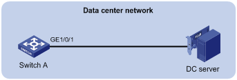
As shown in Figure 8, GigabitEthernet 1/0/1 of the access switch (Switch A) connects to the FCoE adapter of the data center server (DC server).
Configure Switch A to implement lossless FCoE and FIP frame transmission to DC server.
|
|
NOTE: In this example, both Switch A and the DC server support DCBX Rev 1.01. |
Configuration procedure
1. Enable LLDP and DCBX TLV advertising:
# Enable LLDP globally.
<SwitchA> system-view
[SwitchA] lldp global enable
# Enable LLDP and DCBX TLV advertising on GigabitEthernet 1/0/1.
[SwitchA] interface gigabitethernet 1/0/1
[SwitchA-GigabitEthernet1/0/1] lldp enable
[SwitchA-GigabitEthernet1/0/1] lldp tlv-enable dot1-tlv dcbx
2. Set the DCBX version to Rev. 1.01 on GigabitEthernet 1/0/1.
[SwitchA-GigabitEthernet1/0/1] dcbx version rev101
[SwitchA-GigabitEthernet1/0/1] quit
3. Configure APP parameters:
# Create Ethernet frame header ACL 4000.
[SwitchA] acl mac 4000
# Configure ACL 4000 to permit FCoE frames (frame type is 0x8906) and FIP frames (frame type is 0x8914) to pass through.
[SwitchA-acl-mac-4000] rule permit type 8906 ffff
[SwitchA-acl-mac-4000] rule permit type 8914 ffff
[SwitchA-acl-mac-4000] quit
# Create a class named app_c, set the operator of the class to OR, and use ACL 4000 as the match criterion of the class.
[SwitchA] traffic classifier app_c operator or
[SwitchA-classifier-app_c] if-match acl 4000
[SwitchA-classifier-app_c] quit
# Create a traffic behavior named app_b, and configure the traffic behavior to mark packets with 802.1p priority value 3.
[SwitchA] traffic behavior app_b
[SwitchA-behavior-app_b] remark dot1p 3
[SwitchA-behavior-app_b] quit
# Create a QoS policy named plcy, associate class app_c with traffic behavior app_b in the QoS policy, and apply the association to DCBX.
[SwitchA] qos policy plcy
[SwitchA-qospolicy-plcy] classifier app_c behavior app_b mode dcbx
[SwitchA-qospolicy-plcy] quit
# Apply QoS policy plcy to the outgoing traffic of GigabitEthernet 1/0/1.
[SwitchA] interface gigabitethernet 1/0/1
[SwitchA-GigabitEthernet1/0/1] qos apply policy plcy outbound
[SwitchA-GigabitEthernet1/0/1] quit
4. Configure ETS parameters:
# Configure the 802.1p-to-local priority mapping table to map 802.1p priority value 3 to local precedence 3. (This is the default mapping table. You can modify this configuration as needed.)
[SwitchA] qos map-table outbound dot1p-lp
[SwitchA-maptbl-out-dot1p-lp] import 3 export 3
[SwitchA-maptbl-out-dot1p-lp] quit
# Enable byte-count WRR queuing on GigabitEthernet 1/0/1, and configure queue 3 on the interface to use SP queuing.
[SwitchA] interface gigabitethernet 1/0/1
[SwitchA-GigabitEthernet1/0/1] qos wrr byte-count
[SwitchA-GigabitEthernet1/0/1] qos wrr 3 group sp
5. Configure PFC:
# Enable PFC in auto mode on GigabitEthernet 1/0/1.
[SwitchA-GigabitEthernet1/0/1] priority-flow-control auto
# Enable PFC for 802.1 priority 3.
[SwitchA-GigabitEthernet1/0/1] priority-flow-control no-drop dot1p 3
Verifying the configuration
# Display the data exchange result on the DC server through the software interface. This example uses the data exchange result for a QLogic adapter on the DC server.
------------------------------------------------------
DCBX Parameters Details for CNA Instance 0 - QLE8142
------------------------------------------------------
Mon May 17 10:00:50 2010
DCBX TLV (Type-Length-Value) Data
=================================
DCBX Parameter Type and Length
DCBX Parameter Length: 13
DCBX Parameter Type: 2
DCBX Parameter Information
Parameter Type: Current
Pad Byte Present: Yes
DCBX Parameter Valid: Yes
Reserved: 0
DCBX Parameter Data
Priority Group ID of Priority 1: 0
Priority Group ID of Priority 0: 2
Priority Group ID of Priority 3: 15
Priority Group ID of Priority 2: 1
Priority Group ID of Priority 5: 5
Priority Group ID of Priority 4: 4
Priority Group ID of Priority 7: 7
Priority Group ID of Priority 6: 6
Priority Group 0 Percentage: 2
Priority Group 1 Percentage: 4
Priority Group 2 Percentage: 6
Priority Group 3 Percentage: 0
Priority Group 4 Percentage: 10
Priority Group 5 Percentage: 18
Priority Group 6 Percentage: 27
Priority Group 7 Percentage: 31
Number of Traffic Classes Supported: 8
DCBX Parameter Information
Parameter Type: Remote
Pad Byte Present: Yes
DCBX Parameter Valid: Yes
Reserved: 0
DCBX Parameter Data
Priority Group ID of Priority 1: 0
Priority Group ID of Priority 0: 2
Priority Group ID of Priority 3: 15
Priority Group ID of Priority 2: 1
Priority Group ID of Priority 5: 5
Priority Group ID of Priority 4: 4
Priority Group ID of Priority 7: 7
Priority Group ID of Priority 6: 6
Priority Group 0 Percentage: 2
Priority Group 1 Percentage: 4
Priority Group 2 Percentage: 6
Priority Group 3 Percentage: 0
Priority Group 4 Percentage: 10
Priority Group 5 Percentage: 18
Priority Group 6 Percentage: 27
Priority Group 7 Percentage: 31
Number of Traffic Classes Supported: 8
DCBX Parameter Information
Parameter Type: Local
Pad Byte Present: Yes
DCBX Parameter Valid: Yes
Reserved: 0
DCBX Parameter Data
Priority Group ID of Priority 1: 0
Priority Group ID of Priority 0: 0
Priority Group ID of Priority 3: 1
Priority Group ID of Priority 2: 0
Priority Group ID of Priority 5: 0
Priority Group ID of Priority 4: 0
Priority Group ID of Priority 7: 0
Priority Group ID of Priority 6: 0
Priority Group 0 Percentage: 50
Priority Group 1 Percentage: 50
Priority Group 2 Percentage: 0
Priority Group 3 Percentage: 0
Priority Group 4 Percentage: 0
Priority Group 5 Percentage: 0
Priority Group 6 Percentage: 0
Priority Group 7 Percentage: 0
Number of Traffic Classes Supported: 2
The output shows that the DC server will use SP queuing (priority group ID 15) for 802.1p priority 3.
DCBX Parameter Type and Length
DCBX Parameter Length: 2
DCBX Parameter Type: 3
DCBX Parameter Information
Parameter Type: Current
Pad Byte Present: No
DCBX Parameter Valid: Yes
Reserved: 0
DCBX Parameter Data
PFC Enabled on Priority 0: No
PFC Enabled on Priority 1: No
PFC Enabled on Priority 2: No
PFC Enabled on Priority 3: Yes
PFC Enabled on Priority 4: No
PFC Enabled on Priority 5: No
PFC Enabled on Priority 6: No
PFC Enabled on Priority 7: No
Number of Traffic Classes Supported: 6
DCBX Parameter Information
Parameter Type: Remote
Pad Byte Present: No
DCBX Parameter Valid: Yes
Reserved: 0
DCBX Parameter Data
PFC Enabled on Priority 0: No
PFC Enabled on Priority 1: No
PFC Enabled on Priority 2: No
PFC Enabled on Priority 3: Yes
PFC Enabled on Priority 4: No
PFC Enabled on Priority 5: No
PFC Enabled on Priority 6: No
PFC Enabled on Priority 7: No
Number of Traffic Classes Supported: 6
DCBX Parameter Information
Parameter Type: Local
Pad Byte Present: No
DCBX Parameter Valid: Yes
Reserved: 0
DCBX Parameter Data
PFC Enabled on Priority 0: No
PFC Enabled on Priority 1: No
PFC Enabled on Priority 2: No
PFC Enabled on Priority 3: Yes
PFC Enabled on Priority 4: No
PFC Enabled on Priority 5: No
PFC Enabled on Priority 6: No
PFC Enabled on Priority 7: No
Number of Traffic Classes Supported: 1
The output shows that the DC server will use PFC for 802.1p priority 3.
