- Table of Contents
- Related Documents
-
| Title | Size | Download |
|---|---|---|
| 05-S12500_BFD_Configuration_Examples | 362.5 KB |
Contents
General configuration restriction and guidelines
Example: Configuring BFD for the VRRP backup to monitor the master
Example: Configuring BFD for the VRRP master to monitor the uplink
Example: Configuring BFD for OSPF·
Configuration restrictions and guidelines
Example: Configure BFD for IS-IS·
Configuration restrictions and guidelines
Example: Configuring BFD for RIP (single-hop detection in BFD echo packet mode)
Example: Configuring BFD for RIP (bidirectional detection in BFD control packet mode)
Configuration restrictions and guidelines
Example: Configuring BFD for BGP·
Configuration restrictions and guidelines
Example: Configuring BFD echo packet mode for static routing (single-hop detection)
Introduction
This document provides bidirectional forwarding detection (BFD) configuration examples.
Bidirectional forwarding detection (BFD) provides a general-purpose, standard, medium- and protocol-independent fast failure detection mechanism. It can detect and monitor the connectivity of links in IP. BFD can uniformly and quickly detect the failures of the bidirectional forwarding paths between two devices for upper-layer protocols.
Prerequisites
The configuration examples in this document were created and verified in a lab environment, and all the devices were started with the factory default configuration. When you are working on a live network, make sure you understand the potential impact of every command on your network.
This document assumes that you have basic knowledge of BFD.
General configuration restriction and guidelines
IP tunnels, for example, IPv6 over IPv4 tunnels, IPv6 over IPv6 tunnels, IPv4 over IPv6 tunnels, and IPv4 over IPv4 tunnels, do not support BFD.
Example: Configuring BFD for the VRRP backup to monitor the master
Network requirements
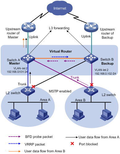
As shown in Figure 1, the enterprise assigns departments to different areas. Devices in each area access the core switches (Switch A and Switch B) through a Layer 2 switch. Create a VRRP group on Switch A and Switch B, and configure Switch A as the master and Switch B as the backup.
Configure BFD to monitor the state of the master on the backup. When the master fails, BFD immediately notifies the VRRP module of the failure. The backup becomes the new master, and link switchover is implemented.
Software version used
This configuration example was created and verified on S12500-CMW520-R1825P01.
Configuration procedures
Configuring Switch A
# Configure the IP address of the VLAN interface.
<SwitchA> system-view
[SwitchA] vlan 2
[SwitchA–vlan2] port GigabitEthernet 3/0/1
[SwitchA–vlan2] quit
[SwitchA] interface GigabitEthernet 3/0/1
[SwitchA-GigabitEthernet3/0/1] undo shutdown
[SwitchA-GigabitEthernet3/0/1] quit
[SwitchA] interface vlan-interface 2
[SwitchA–Vlan-interface2] undo shutdown
[SwitchA–Vlan-interface2] ip address 192.168.0.101 24
# Create VRRP group 1, and configure the virtual IP address for the VRRP group.
[SwitchA–Vlan-interface2] vrrp vrid 1 virtual-ip 192.168.0.10
# Set the priority of Switch A in VRRP group 1 to 110, which is higher than the priority of Switch B (default setting 100).
[SwitchA–Vlan-interface2] vrrp vrid 1 priority 110
[SwitchA–Vlan-interface2] return
Configuring Switch B
# Configure the IP address of the VLAN-interface.
<SwitchB> system-view
[SwitchB] vlan 2
[SwitchB–vlan2] port GigabitEthernet 3/0/1
[SwitchB–vlan2] quit
[SwitchB] interface GigabitEthernet 3/0/1
[SwitchB-GigabitEthernet3/0/1] undo shutdown
[SwitchB-GigabitEthernet3/0/1] quit
[SwitchB] interface vlan-interface 2
[SwitchB–Vlan-interface2] undo shutdown
[SwitchB–Vlan-interface2] ip address 192.168.0.102 24
# Create VRRP group 1, and configure the virtual IP address for the VRRP group.
[SwitchB–Vlan-interface2] vrrp vrid 1 virtual-ip 192.168.0.10
[SwitchB–Vlan-interface2] quit
# Configure the source IP address of BFD echo packets (VRRP supports only BFD echo packet mode), which cannot be on the same network segment as any local interface's IP address.
[SwitchB] bfd echo-source-ip 10.10.10.10
# Configure the minimum BFD echo packet receiving interval on the interface and the detection multiplier.
[SwitchB] interface vlan-interface 2
[SwitchB–Vlan-interface2] bfd min-echo-receive-interval 10
[SwitchB–Vlan-interface2] bfd detect-multiplier 3
[SwitchB–Vlan-interface2] quit
# Create the track object.
[SwitchB] track 1 bfd echo interface vlan-interface 2 remote ip 192.168.0.101 local ip 192.168.0.102
[SwitchB] interface vlan-interface 2
# Configure VRRP to monitor the status of track entry 1. When the status of the track entry becomes Negative, Switch B quickly becomes the master.
[SwitchB–Vlan-interface2] vrrp vrid 1 track 1 switchover
[SwitchB–Vlan-interface2] return
Verifying the configuration
# Display the detailed information of VRRP group 1 on Switch A.
<SwitchA> display vrrp verbose
IPv4 Standby Information:
Run Mode : Standard
Run Method : Virtual MAC
Total number of virtual routers : 1
Interface Vlan-interface2
VRID : 1 Adver Timer : 1
Admin Status : Up State : Master
Config Pri : 110 Running Pri : 110
Preempt Mode : Yes Delay Time : 0
Auth Type : None
Virtual IP : 192.168.0.10
Virtual MAC : 0000-5e00-0101
Master IP : 192.168.0.101
# Display the detailed information of VRRP group 1 on Switch B.
<SwitchB> display vrrp verbose
IPv4 Standby Information:
Run Mode : Standard
Run Method : Virtual MAC
Total number of virtual routers : 1
Interface Vlan-interface2
VRID : 1 Adver Timer : 1
Admin Status : Up State : Backup
Config Pri : 100 Running Pri : 100
Preempt Mode : Yes Delay Time : 0
Become Master : 3100ms left
Auth Type : None
Virtual IP : 192.168.0.10
Master IP : 192.168.0.101
VRRP Track Information:
Track Object : 1 State : Positive Switchover
# Display BFD session information.
<SwitchB> display bfd session
Total session number: 1 Up session number: 1 Init mode: Active
IPv4 session working under Echo mode:
LD SourceAddr DestAddr State Holdtime Interface
1 192.168.0.102 192.168.0.101 Up 30ms Vlan2
The output shows that Switch A in VRRP group 1 is the master and Switch B is the backup.
# When Switch A is down, use the display vrrp command to display the state information of the VRRP group. (Switch B becomes the master.)
<SwitchB> display vrrp verbose
IPv4 Standby Information:
Run Mode : Standard
Run Method : Virtual MAC
Total number of virtual routers : 1
Interface Vlan-interface2
VRID : 1 Adver Timer : 1
Admin Status : Up State : Master
Config Pri : 100 Running Pri : 100
Preempt Mode : Yes Delay Time : 0
Auth Type : None
Virtual IP : 192.168.1.10
Virtual MAC : 0000-5e00-0101
Master IP : 192.168.1.102
VRRP Track Information:
Track Object : 1 State : Negative Switchover
# Display BFD session information.
<SwitchB> display bfd session
Total session number: 1 Up session number: 1 Init mode: Active
IPv4 session working under Echo mode:
LD SourceAddr DestAddr State Holdtime Interface
1 192.168.0.102 192.168.0.101 Down / Vlan2
# Display the detailed information of the track object on Switch B. (The track entry status is Negative.)
<SwitchB> display track 1
Track ID: 1
Status: Negative
Duration: 0 days 0 hours 1 minutes 17 seconds
Notification delay: Positive 0, Negative 0 (in seconds)
Reference object:
BFD session:
Packet type: Echo
Interface : Vlan-interface2
Remote IP : 192.168.1.101
Local IP : 192.168.1.102
Configuration files
· Switch A:
#
vlan 2
#
interface Vlan-interface2
ip address 192.168.0.101 255.255.255.0
vrrp vrid 1 virtual-ip 192.168.0.10
vrrp vrid 1 priority 110
#
interface GigabitEthernet3/0/1
port link-mode bridge
port access vlan 2
#
· Switch B:
#
bfd echo-source-ip 10.10.10.10
#
vlan 2
#
interface Vlan-interface2
ip address 192.168.0.102 255.255.255.0
bfd min-echo-receive-interval 10
bfd detect-multiplier 3
vrrp vrid 1 virtual-ip 192.168.0.10
vrrp vrid 1 track 1 switchover
#
interface GigabitEthernet3/0/1
port link-mode bridge
port access vlan 2
#
track 1 bfd echo interface Vlan-interface2 remote ip 192.168.0.101 local ip 192.168.0.102
#
Example: Configuring BFD for the VRRP master to monitor the uplink
Network requirements
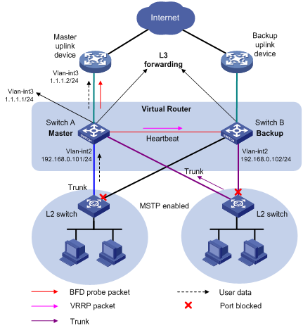
As shown in Figure 2, the enterprise assigns departments to different areas. Devices in each area access the core switches (Switch A and Switch B) through a Layer 2 switch. Create a VRRP group on Switch A and Switch B, and configure Switch A as the master and Switch B as the backup.
When the uplink of the master fails, VRRP cannot detect the failure, and users still forward traffic to the master (Switch A). To resolve this issue, configure BFD to monitor the state of uplink on the master. When the uplink of the master fails, BFD immediately notifies the VRRP module of the failure. The backup becomes the new master, and link switchover is implemented.
Software version used
This configuration example was created and verified on S12500-CMW520-R1825P01.
Configuration procedures
Configuring Switch A
# Configure the uplink VLAN interface and its IP address.
<SwitchA> system-view
[SwitchA] vlan 3
[SwitchA–vlan3] port GigabitEthernet 3/0/1
[SwitchA–vlan3] quit
[SwitchA] interface GigabitEthernet 3/0/1
[SwitchA-GigabitEthernet3/0/1] undo shutdown
[SwitchA-GigabitEthernet3/0/1] quit
[SwitchA] interface vlan-interface 3
[SwitchA–Vlan-interface3] undo shutdown
[SwitchA–Vlan-interface3] ip address 1.1.1.1 24
[SwitchA–Vlan-interface3] quit
# Configure the VLAN interface to be enabled with VRRP, and configure its IP address.
[SwitchA] vlan 2
[SwitchA–vlan2] port GigabitEthernet 3/0/2
[SwitchA–vlan2] quit
[SwitchA] interface GigabitEthernet 3/0/2
[SwitchA-GigabitEthernet3/0/2] undo shutdown
[SwitchA-GigabitEthernet3/0/2] quit
[SwitchA] interface vlan-interface 2
[SwitchA–Vlan-interface2] undo shutdown
[SwitchA–Vlan-interface2] ip address 192.168.0.101 24
# Create VRRP group 1, and configure the virtual IP address for the VRRP group.
[SwitchA–Vlan-interface2] vrrp vrid 1 virtual-ip 192.168.0.10
# Set the priority of Switch A in VRRP group 1 to 110, which is higher than the priority of Switch B (default setting 100).
[SwitchA–Vlan-interface2] vrrp vrid 1 priority 110
[SwitchA–Vlan-interface2] quit
# Configure the source IP address of BFD echo packets (VRRP supports only BFD echo packet mode), which cannot be on the same network segment as any local interface's IP address.
[SwitchA] bfd echo-source-ip 10.10.10.10
# Configure the minimum BFD echo packet receiving interval on the interface.
[SwitchA] interface vlan-interface 3
[SwitchA–Vlan-interface3] bfd min-echo-receive-interval 10
# Configure the detection multiplier.
[SwitchA–Vlan-interface3] bfd detect-multiplier 3
[SwitchA–Vlan-interface3] quit
# Create the track entry associated with the BFD session, and specify the local and remote IP addresses of BFD echo packets.
[SwitchA] track 1 bfd echo interface vlan-interface 3 remote ip 1.1.1.2 local ip 1.1.1.1
# Configure VRRP group 1 to monitor the status of track entry 1. When the status of the track entry becomes Negative, the priority of Switch A decreases by 20. Switch B then becomes the new master, and link switchover is implemented.
[SwitchA] interface vlan-interface 2
[SwitchA–Vlan-interface2] vrrp vrid 1 track 1 reduced 20
[SwitchA–Vlan-interface2] return
Configuring Switch B
# Configure the VLAN interface to be enabled with VRRP and its IP address.
<SwitchB> system-view
[SwitchB] vlan 2
[SwitchB–vlan2] port GigabitEthernet 3/0/1
[SwitchB–vlan2] quit
[SwitchB] interface GigabitEthernet 3/0/1
[SwitchB-GigabitEthernet3/0/1] undo shutdown
[SwitchB-GigabitEthernet3/0/1] quit
[SwitchB] interface vlan-interface 2
[SwitchB–Vlan-interface2] undo shutdown
[SwitchB–Vlan-interface2] ip address 192.168.0.102 24
# Create VRRP group 1 and configure its virtual IP address.
[SwitchB–Vlan-interface2] vrrp vrid 1 virtual-ip 192.168.0.10
[SwitchB–Vlan-interface2] return
Verifying the configuration
# Display the detailed information of VRRP group 1 on Switch A.
<SwitchA> display vrrp verbose
IPv4 Standby Information:
Run Mode : Standard
Run Method : Virtual MAC
Total number of virtual routers : 1
Interface Vlan-interface2
VRID : 1 Adver Timer : 1
Admin Status : Up State : Master
Config Pri : 110 Running Pri : 110
Preempt Mode : Yes Delay Time : 0
Auth Type : None
Virtual IP : 192.168.0.10
Virtual MAC : 0000-5e00-0101
Master IP : 192.168.0.101
VRRP Track Information:
Track Object : 1 State : Positive Pri Reduced : 20
# Display the detailed information of VRRP group 1 on Switch B.
<SwitchB> display vrrp verbose
IPv4 Standby Information:
Run Mode : Standard
Run Method : Virtual MAC
Total number of virtual routers : 1
Interface Vlan-interface2
VRID : 1 Adver Timer : 1
Admin Status : Up State : Backup
Config Pri : 100 Running Pri : 100
Preempt Mode : Yes Delay Time : 0
Become Master : 3100ms left
Auth Type : None
Virtual IP : 192.168.0.10
Master IP : 192.168.0.101
# Display BFD session information on Switch A.
<SwitchA> display bfd session
Total session number: 1 Up session number: 1 Init mode: Active
IPv4 session working under Echo mode:
LD SourceAddr DestAddr State Holdtime Interface
1 1.1.1.1 1.1.1.2 Up 30ms Vlan3
The output shows that Switch A in VRRP group 1 is the master and Switch B is the backup.
# When the uplink monitored by Switch A is down, use the display vrrp command to display the state information of the VRRP group. When the uplink monitored by Switch A is down, display the detailed VRRP group information of Switch A.
<SwitchA> display vrrp verbose
IPv4 Standby Information:
Run Mode : Standard
Run Method : Virtual MAC
Total number of virtual routers : 1
Interface Vlan-interface2
VRID : 1 Adver Timer : 1
Admin Status : Up State : Backup
Config Pri : 110 Running Pri : 90
Preempt Mode : Yes Delay Time : 0
Become Master : 3100ms left
Auth Type : None
Virtual IP : 192.168.0.10
Master IP : 192.168.0.102
VRRP Track Information:
Track Object : 1 State : Negative Pri Reduced : 20
# When the uplink monitored by Switch A is down, display the detailed VRRP group information of Switch B.
<SwitchB> display vrrp verbose
IPv4 Standby Information:
Run Mode : Standard
Run Method : Virtual MAC
Total number of virtual routers : 1
Interface Vlan-interface2
VRID : 1 Adver Timer : 1
Admin Status : Up State : Master
Config Pri : 100 Running Pri : 100
Preempt Mode : Yes Delay Time : 0
Auth Type : None
Virtual IP : 192.168.0.10
Virtual MAC : 0000-5e00-0101
Master IP : 192.168.0.102
# Display BFD session information on Switch A.
<SwitchA> display bfd session
Total session number: 1 Up session number: 1 Init mode: Active
IPv4 session working under Echo mode:
LD SourceAddr DestAddr State Holdtime Interface
1 1.1.1.1 1.1.1.2 Down / Vlan2
# Display the detailed information of the track object on Switch A.
<SwitchA> display track 1
Track ID: 1
Status: Negative
Duration: 0 days 0 hours 3 minutes 33 seconds
Notification delay: Positive 0, Negative 0 (in seconds)
Reference object:
BFD session:
Packet type: Echo
Interface : Vlan-interface3
Remote IP : 1.1.12
Local IP : 1.1.1.1
Configuration files
· Switch A:
#
bfd echo-source-ip 10.10.10.10
#
vlan 2
#
vlan 3
#
interface Vlan-interface2
ip address 192.168.0.101 255.255.255.0
vrrp vrid 1 virtual-ip 192.168.0.10
vrrp vrid 1 priority 110
vrrp vrid 1 track 1 reduced 20
#
interface Vlan-interface3
ip address 1.1.1.1 255.255.255.0
bfd min-echo-receive-interval 10
bfd detect-multiplier 3
#
interface GigabitEthernet3/0/1
port link-mode bridge
port access vlan 3
#
interface GigabitEthernet3/0/2
port link-mode bridge
port access vlan 2
#
track 1 bfd echo interface Vlan-interface3 remote ip 1.1.1.2 local ip 1.1.1.1
#
· Switch B:
#
vlan 2
#
vlan 3
#
interface Vlan-interface2
ip address 192.168.0.102 255.255.255.0
vrrp vrid 1 virtual-ip 192.168.0.10
#
interface GigabitEthernet3/0/1
port link-mode bridge
port access vlan 2
#
Example: Configuring BFD for OSPF
Network requirements
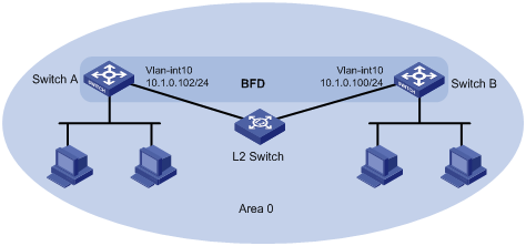
As shown in Figure 3, the egress switches (Switch A and Switch B) of two departments are connected through a Layer 2 switch. Run OSPF on Switch A and Switch B so that they can establish neighbor relationship.
When the link between Switch B and the Layer 2 switch fails, Switch A cannot detect the failure until the neighbor relationship with Switch B is terminated. To implement fast link fault detection, configure BFD for OSPF. When the link between Switch B and the Layer 2 switch fails, Switch A can quickly detect the failure and displays prompt messages for the network administrator to locate the link fault.
Software version used
This configuration example was created and verified on S12500-CMW520-R1825P01.
Configuration restrictions and guidelines
In BFD control packet mode, at least one end must operate in active mode for a BFD session to be established.
Configuration procedures
Configuring Switch A
# Create a VLAN interface and configure its IP address.
<SwitchA> system-view
[SwitchA] vlan 10
[SwitchA-vlan10] port GigabitEthernet 3/0/1
[SwitchA-vlan10] quit
[SwitchA] interface GigabitEthernet 3/0/1
[SwitchA-GigabitEthernet3/0/1] undo shutdown
[SwitchA-GigabitEthernet3/0/1] quit
[SwitchA] interface vlan-interface 10
[SwitchA-Vlan-interface10] undo shutdown
[SwitchA-Vlan-interface10] ip address 10.1.0.102 24
[SwitchA-Vlan-interface10] quit
# Configure OSPF basic functions and enable BFD for OSPF (OSPF supports only BFD control packet mode).
[SwitchA] ospf
[SwitchA-ospf-1] area 0
[SwitchA-ospf-1-area-0.0.0.0] network 10.1.0.0 0.0.0.255
[SwitchA-ospf-1-area-0.0.0.0] quit
[SwitchA-ospf-1] quit
[SwitchA] interface vlan-interface 10
[SwitchA-Vlan-interface10] ospf bfd enable
[SwitchA-Vlan-interface10] quit
# Configure BFD operating mode and relevant parameters.
[SwitchA] bfd session init-mode active
[SwitchA] interface vlan-interface 10
[SwitchA-Vlan-interface10] bfd min-transmit-interval 100
[SwitchA-Vlan-interface10] bfd min-receive-interval 100
[SwitchA-Vlan-interface10] bfd detect-multiplier 3
[SwitchA-Vlan-interface10] quit
[SwitchA] quit
Configuring Switch B
# Create a VLAN interface and configure its IP address.
<SwitchB> system-view
[SwitchB] vlan 10
[SwitchB-vlan10] port GigabitEthernet 3/0/2
[SwitchB-vlan10] quit
[SwitchB] interface GigabitEthernet 3/0/2
[SwitchB-GigabitEthernet3/0/2] undo shutdown
[SwitchB-GigabitEthernet3/0/2] quit
[SwitchB] interface vlan-interface 10
[SwitchB-Vlan-interface10] undo shutdown
[SwitchB-Vlan-interface10] ip address 10.1.0.100 24
[SwitchB-Vlan-interface10] quit
# Configure OSPF basic functions and enable BFD for OSPF (OSPF supports only BFD control packet mode).
[SwitchB] ospf
[SwitchB-ospf-1] area 0
[SwitchB-ospf-1-area-0.0.0.0] network 10.1.0.0 0.0.0.255
[SwitchB-ospf-1-area-0.0.0.0] quit
[SwitchB-ospf-1] quit
[SwitchB] interface vlan-interface 10
[SwitchB-Vlan-interface10] ospf bfd enable
[SwitchB-Vlan-interface10] quit
# Configure BFD operating mode and relevant parameters.
[SwitchB] bfd session init-mode active
[SwitchB] interface vlan 10
[SwitchB-Vlan-interface10] bfd min-transmit-interval 100
[SwitchB-Vlan-interface10] bfd min-receive-interval 100
[SwitchB-Vlan-interface10] bfd detect-multiplier 3
[SwitchB-Vlan-interface10] quit
[SwitchB] quit
Verifying the configuration
# Display information about OSPF neighbors.
[SwitchA]display ospf peer verbose
OSPF Process 1 with Router ID 2.2.2.2
Neighbors
Area 0.0.0.0 interface 10.1.0.102(Vlan-interface10)'s neighbors
Router ID: 1.1.1.1 Address: 10.1.0.100 GR State: Normal
State: Full Mode: Nbr is Slave Priority: 1
DR: 10.1.0.102 BDR: 10.1.0.100 MTU: 0
Dead timer due in 32 sec
Neighbor is up for 00:21:37
Authentication Sequence: [ 0 ]
Neighbor state change count: 5
Last Neighbor Down Event:
Router ID: 1.1.1.1
Local Address: 10.1.0.102
Remote Address: 10.1.0.100
Time: Jan 7 10:04:26 2009
Reason: DeadInterval timer expired
# Display BFD session information. A BFD session is created and is up.
[SwitchA] display bfd session verbose
Total session number: 1 Up session number: 1 Init mode: Active
IPv4 session working under Ctrl mode:
Local Discr: 10 Remote Discr: 1
Source IP: 10.1.0.102 Destination IP: 10.1.0.100
Session State: Up Interface: Vlan-interface10
Min Trans Inter: 100ms Act Trans Inter: 100ms
Min Recv Inter: 100ms Act Detect Inter: 300ms
Running Up for: 00:24:03 Auth mode: None
Connect Type: Direct Board Num: 0
Protocol: OSPF
Diag Info: No Diagnostic
[SwitchB] display bfd session verbose
Total session number: 1 Up session number: 1 Init mode: Active
IPv4 session working under Ctrl mode:
Local Discr: 1 Remote Discr: 10
Source IP: 10.1.0.100 Destination IP: 10.1.0.102
Session State: Up Interface: Vlan-interface10
Min Trans Inter: 100ms Act Trans Inter: 100ms
Min Recv Inter: 100ms Act Detect Inter: 300ms
Running Up for: 00:27:56 Auth mode: None
Connect Type: Direct Board Num: 1
Protocol: OSPF
Diag Info: No Diagnostic
When the link between Switch B and the Layer 2 switch fails, BFD can quickly detect the failure and notify OSPF of the failure.
%Apr 2 11:34:26:880 2013 SwitchA BFD/5/BFD_CHANGE_FSM: Sess[10.1.0.102/10.1.0.100,1026/1026
,Vlan10,Ctrl], Sta: UP->DOWN, Diag: 5
%Apr 2 11:34:27:011 2013 SwitchA OSPF/5/OSPF_NBR_CHG: OSPF 1 Neighbor 10.1.0.100Vlan-interface10) from Full to Down.
# Execute the display ospf peer verbose command. The OSPF neighbor state changes to down.
[SwitchA] display ospf peer verbose
OSPF Process 1 with Router ID 2.2.2.2
Last Neighbor Down Event:
Router ID: 1.1.1.1
Local Address: 10.1.0.102
Remote Address: 10.1.0.100
Time: Apr 2 11:34:47 2013
Reason: BFD session down
Configuration files
· Switch A:
#
Vlan 10
#
interface Vlan-interface10
ip address 10.1.0.102 255.255.255.0
ospf bfd enable
bfd min-transmit-interval 100
bfd min-receive-interval 100
bfd detect-multiplier 3
#
interface GigabitEthernet3/0/1
port link-mode bridge
port access vlan 10
#
ospf 1
area 0.0.0.0
network 10.1.0.0 0.0.0.255
#
· Switch B:
#
Vlan 10
#
interface Vlan-interface10
ip address 10.1.0.100 255.255.255.0
ospf bfd enable
bfd min-transmit-interval 100
bfd min-receive-interval 100
bfd detect-multiplier 3
#
interface GigabitEthernet3/0/2
port link-mode bridge
port access vlan 10
#
ospf 1
area 0.0.0.0
network 10.1.0.0 0.0.0.255
#
Example: Configure BFD for IS-IS
Network requirements
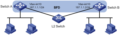
As shown in Figure 4, the egress switches (Switch A and Switch B) of two departments are connected through a Layer 2 switch. Run IS-IS on Switch A and Switch B so that they can establish neighbor relationship.
When the link between Switch B and the Layer 2 switch fails, Switch A cannot detect the failure until the neighbor relationship with Switch B is terminated. To implement fast link fault detection, configure BFD for IS-IS. When the link between Switch B and the Layer 2 switch fails, Switch A can quickly detect the failure and displays prompt messages for the network administrator to locate the link fault.
Software version used
This configuration example was created and verified on S12500-CMW520-R1825P01.
Configuration restrictions and guidelines
In BFD control packet mode, at least one end must operate in active mode for a BFD session to be established.
Configuration procedures
Configuring Switch A
# Create a VLAN interface and configure its IP address.
<SwitchA> system-view
[SwitchA] vlan 10
[SwitchA-vlan10] port GigabitEthernet 3/0/1
[SwitchA-vlan10] quit
[SwitchA] interface GigabitEthernet 3/0/1
[SwitchA-GigabitEthernet3/0/1] undo shutdown
[SwitchA-GigabitEthernet3/0/1] quit
[SwitchA] interface vlan-interface 10
[SwitchA-Vlan-interface10] undo shutdown
[SwitchA-Vlan-interface10] ip address 167.1.1.1 24
[SwitchA-Vlan-interface10] quit
# Configure IS-IS basic functions and enable BFD for IS-IS (IS-IS supports only BFD control packet mode).
[SwitchA] isis
[SwitchA-isis-1] network-entity 00.0000.0000.0000.0001.00
[SwitchA-isis-1] quit
[SwitchA] interface vlan-interface 10
[SwitchA-Vlan-interface10] isis enable
[SwitchA-Vlan-interface10] isis bfd enable
[SwitchA-Vlan-interface10] quit
# Configure BFD operating mode and relevant parameters.
[SwitchA] bfd session init-mode active
[SwitchA] interface vlan-interface 10
[SwitchA-Vlan-interface10] bfd min-transmit-interval 100
[SwitchA-Vlan-interface10] bfd min-receive-interval 100
[SwitchA-Vlan-interface10] bfd detect-multiplier 3
[SwitchA-Vlan-interface10] quit
[SwitchA] quit
Configuring Switch B
# Create a VLAN interface and configure its IP address.
<SwitchB> system-view
[SwitchB] vlan 10
[SwitchB-vlan10] port GigabitEthernet 3/0/2
[SwitchB-vlan10] quit
[SwitchB] interface GigabitEthernet 3/0/2
[SwitchB-GigabitEthernet3/0/2] undo shutdown
[SwitchB-GigabitEthernet3/0/2] quit
[SwitchB] interface vlan-interface 10
[SwitchB-Vlan-interface10] undo shutdown
[SwitchB-Vlan-interface10] ip address 167.1.1.2 24
[SwitchB-Vlan-interface10] quit
# Configure IS-IS basic functions and enable BFD for IS-IS (IS-IS supports only BFD control packet mode).
[SwitchB] isis
[SwitchB-isis-1] network-entity 00.0000.0000.0000.0002.00
[SwitchB-isis-1] quit
[SwitchB] interface vlan-interface 10
[SwitchB-Vlan-interface10] isis enable
[SwitchB-Vlan-interface10] isis bfd enable
[SwitchB-Vlan-interface10] quit
# Configure BFD operating mode and relevant parameters.
[SwitchB] bfd session init-mode active
[SwitchB] interface vlan-interface 10
[SwitchB-Vlan-interface10] bfd min-transmit-interval 100
[SwitchB-Vlan-interface10] bfd min-receive-interval 100
[SwitchB-Vlan-interface10] bfd detect-multiplier 3
[SwitchB-Vlan-interface10] quit
[SwitchB] quit
Verifying the configuration
# Display information about IS-IS neighbors.
[SwitchA] display isis peer verbose
Peer information for ISIS(1)
----------------------------
System Id: 0000.0000.0002
Interface: Vlan10 Circuit Id: 0000.0000.0001.01
State: Up HoldTime: 29s Type: L1(L1L2) PRI: 64
Area Address(es):00.0000
Peer IP Address(es): 167.1.1.2
Uptime: 00:21:20
Adj Protocol: IPv4
System Id: 0000.0000.0002
Interface: Vlan10 Circuit Id: 0000.0000.0001.01
State: Up HoldTime: 30s Type: L2(L1L2) PRI: 64
Area Address(es):00.0000
Peer IP Address(es): 167.1.1.2
Uptime: 00:21:16
Adj Protocol: IPv4
# Display BFD session information. A BFD session is created and is up.
[SwitchA] display bfd session verbose
Total session number: 1 Up session number: 1 Init mode: Active
IPv4 session working under Ctrl mode:
Local Discr: 11 Remote Discr: 2
Source IP: 167.1.1.1 Destination IP: 167.1.1.2
Session State: Up Interface: Vlan-interface10
Min Trans Inter: 100ms Act Trans Inter: 100ms
Min Recv Inter: 100ms Act Detect Inter: 300ms
Running Up for: 00:22:14 Auth mode: None
Connect Type: Direct Board Num: 0
Protocol: ISIS_BR_L1/ISIS_BR_L2
Diag Info: No Diagnostic
[SwitchB] display bfd session verbose
Total session number: 1 Up session number: 1 Init mode: Active
IPv4 session working under Ctrl mode:
Local Discr: 2 Remote Discr: 11
Source IP: 167.1.1.2 Destination IP: 167.1.1.1
Session State: Up Interface: Vlan-interface10
Min Trans Inter: 100ms Act Trans Inter: 100ms
Min Recv Inter: 100ms Act Detect Inter: 300ms
Running Up for: 00:23:52 Auth mode: None
Connect Type: Direct Board Num: 1
Protocol: ISIS_BR_L1/ISIS_BR_L2
Diag Info: No Diagnostic
When the link between Switch B and the Layer 2 switch fails, BFD can quickly detect the failure and notify IS-IS of the failure.
%Apr 2 13:43:37:133 2013 SwitchA BFD/5/BFD_CHANGE_FSM: Sess[167.1.1.1/167.1.1.2,1025/1025
,Vlan10,Ctrl], Sta: UP->DOWN, Diag: 5
%Apr 2 13:43:37:265 2013 SwitchA ISIS/5/ISIS_NBR_CHG: ISIS 1 Adjacency to 0000.0000.0
002 (Vlan10) DOWN, Level-1 Adjacency clear.
%Apr 2 13:43:37:396 2013 SwitchA ISIS/5/ISIS_NBR_CHG: ISIS 1 Adjacency to 0000.0000.0
002 (Vlan10) DOWN, Level-2 Adjacency clear.
Configuration files
· Switch A:
#
vlan 10
#
isis 1
network-entity 00.0000.0000.0000.0001.00
#
interface Vlan-interface10
ip address 167.1.1.1 255.255.255.0
isis enable 1
isis bfd enable
bfd min-transmit-interval 100
bfd min-receive-interval 100
bfd detect-multiplier 3
#
interface GigabitEthernet3/0/1
port link-mode bridge
port access vlan 10
#
· Switch B:
#
vlan 10
#
isis 1
network-entity 00.0000.0000.0000.0002.00
#
interface Vlan-interface10
ip address 167.1.1.2 255.255.255.0
isis enable 1
isis bfd enable
bfd min-transmit-interval 100
bfd min-receive-interval 100
bfd detect-multiplier 3
#
interface GigabitEthernet3/0/2
port link-mode bridge
port access vlan 10
#
Example: Configuring BFD for RIP (single-hop detection in BFD echo packet mode)
Network requirements
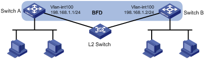
As shown in Figure 5, the egress switches (Switch A and Switch B) of two departments are connected through a Layer 2 switch. Run RIP on Switch A and Switch B so that they can establish neighbor relationship.
When the link between Switch B and the Layer 2 switch fails, Switch A cannot detect the failure until the neighbor relationship with Switch B is terminated. To implement fast link fault detection, configure BFD for RIP. When the link between Switch B and the Layer 2 switch fails, Switch A can quickly detect the failure and displays prompt messages for the network administrator to locate the link fault.
Software version used
This configuration example was created and verified on S12500-CMW520-R1825P01.
Configuration procedures
Configuring Switch A
# Create a VLAN interface and configure its IP address.
<SwitchA> system-view
[SwitchA] vlan 100
[SwitchA-vlan100] port GigabitEthernet 3/0/1
[SwitchA-vlan100] quit
[SwitchA] interface GigabitEthernet 3/0/1
[SwitchA-GigabitEthernet3/0/1] undo shutdown
[SwitchA-GigabitEthernet3/0/1] quit
[SwitchA] interface vlan-interface 100
[SwitchA-Vlan-interface100] undo shutdown
[SwitchA-Vlan-interface100] ip address 198.168.1.1 24
[SwitchA-Vlan-interface100] quit
# Configure RIP basic functions and enable BFD for RIP.
[SwitchA] rip 1
[SwitchA-rip-1] network 198.168.1.0
[SwitchA-rip-1] import-route direct
[SwitchA-rip-1] quit
[SwitchA] interface vlan-interface 100
[SwitchA-Vlan-interface100] rip bfd enable
[SwitchA-Vlan-interface100] quit
# Configure BFD parameters. (Because Switch B is one hop away, you only need to configure BFD echo packet mode.)
[SwitchA] bfd echo-source-ip 11.11.11.11
[SwitchA] interface vlan-interface 100
[SwitchA-Vlan-interface100] bfd min-echo-receive-interval 100
[SwitchA-Vlan-interface100] bfd detect-multiplier 3
[SwitchA-Vlan-interface100] quit
[SwitchA] quit
Configuring Switch B
# Create a VLAN interface and configure its IP address.
<SwitchB> system-view
[SwitchB] vlan 100
[SwitchB-vlan100] port GigabitEthernet 3/0/2
[SwitchB-vlan100] quit
[SwitchB] interface GigabitEthernet 3/0/2
[SwitchB-GigabitEthernet3/0/2] undo shutdown
[SwitchB-GigabitEthernet3/0/2] quit
[SwitchB] interface vlan-interface 100
[SwitchB-Vlan-interface100] undo shutdown
[SwitchB-Vlan-interface100] ip address 198.168.1.2 24
[SwitchB-Vlan-interface100] quit
# Configure RIP basic functions and enable direct route redistribution (so that Switch B sends all direct routes to Switch A).
[SwitchB] rip 1
[SwitchB-rip-1] network 198.168.1.0
[SwitchB-rip-1] import-route direct
[SwitchB-rip-1] quit
Verifying the configuration
# Display RIP route information on Switch A. Switch A learns the direct route advertised by Switch B.
[SwitchA] display ip routing-table protocol rip
Public Routing Table : RIP
Summary Count : 4
RIP Routing table Status : < Active>
Summary Count : 1
Destination/Mask Proto Pre Cost NextHop Interface
53.0.0.0/24 RIP 100 1 198.168.1.2 Vlan100
RIP Routing table Status : < Inactive>
Summary Count : 3
Destination/Mask Proto Pre Cost NextHop Interface
20.0.0.0/24 RIP 100 1 198.168.1.2 Vlan100
30.0.0.0/24 RIP 100 1 198.168.1.2 Vlan100
100.0.0.0/16 RIP 100 1 198.168.1.2 Vlan100
# Display BFD session information. A BFD session is created and is up.
[SwitchA] display bfd session verbose
Total session number: 1 Up session number: 1 Init mode: Active
IPv4 session working under Ctrl mode:
Local Discr: 1391
Source IP: 198.168.1.1 Destination IP: 198.168.1.2
Session State: Up Interface: Vlan-interface100
Min Recv Inter: 100ms Act Trans Inter: 100ms
Act Detect Inter: 300ms Running Up for: 00:51:31
Connect Type: Direct Board Num: 1
Protocol: RIP
Diag Info: No Diagnostic
When the link between Switch B and the Layer 2 switch fails, BFD can quickly detect the failure and notify RIP of the failure.
%Apr 2 13:52:02:638 2013 SwitchA BFD/5/BFD_CHANGE_FSM: Sess[192.168.1.1/192.168.1.2,1027/0,Vlan100,Echo], Sta: UP->DOWN, Diag: 5
# Display information about RIP routes. The routes learned through RIP are deleted.
[SwitchA] display ip routing-table protocol rip
Public Routing Table : RIP
Summary Count : 0
RIP Routing table Status : < Active>
Summary Count : 0
RIP Routing table Status : < Inactive>
Summary Count : 0
Configuration files
· Switch A:
#
bfd echo-source-ip 11.11.11.11
#
vlan 100
#
interface Vlan-interface100
ip address 198.168.1.1 255.255.255.0
rip bfd enable
bfd min-echo-receive-interval 100
bfd detect-multiplier 3
#
interface GigabitEthernet3/0/1
port link-mode bridge
port access vlan 100
#
rip 1
network 198.168.1.0
import-route direct
#
· Switch B:
#
vlan 100
#
interface Vlan-interface100
ip address 198.168.1.2 255.255.255.0
#
interface GigabitEthernet3/0/2
port link-mode bridge
port access vlan 100
#
rip 1
network 198.168.1.0
import-route direct
#
Example: Configuring BFD for RIP (bidirectional detection in BFD control packet mode)
Network requirements
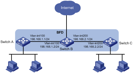
As shown in Figure 6, the egress switches (Switch A and Switch C) of two departments are connected to the Internet through a core switch Switch B. Configure static routes between Switch A and Switch C, and establish RIP neighbor relationship between them.
When the link between Switch A and Switch B or between Switch B and Switch C fails, the switches cannot detect the failure until the RIP neighbor relationship is terminated. To implement fast link fault detection, configure BFD for RIP. When the link between Switch A and Switch B or between Switch B and Switch C fails, Switch A and Switch C can quickly detect the failure and displays prompt messages for the network administrator to locate the link fault.
Software version used
This configuration example was created and verified on S12500-CMW520-R1825P01.
Configuration restrictions and guidelines
In BFD control packet mode, at least one end must operate in active mode for a BFD session to be established.
Configuration procedures
Configuring Switch A
# Create a VLAN interface and configure its IP address.
<SwitchA> system-view
[SwitchA] vlan 100
[SwitchA-vlan100] port GigabitEthernet 3/0/1
[SwitchA-vlan100] quit
[SwitchA] interface GigabitEthernet 3/0/1
[SwitchA-GigabitEthernet3/0/1] undo shutdown
[SwitchA-GigabitEthernet3/0/1] quit
[SwitchA] interface vlan-interface 100
[SwitchA-Vlan-interface100] undo shutdown
[SwitchA-Vlan-interface100] ip address 198.168.1.1 24
[SwitchA-Vlan-interface100] quit
# Configure RIP basic functions and enable BFD for RIP. (Because Switch C is not directly connected, you must configure BFD control packet mode.)
[SwitchA] rip 1
[SwitchA-rip-1] network 198.168.1.0
[SwitchA-rip-1] peer 198.168.2.2
[SwitchA-rip-1] undo validate-source-address
[SwitchA-rip-1] import-route direct
[SwitchA-rip-1] quit
[SwitchA] interface vlan-interface 100
[SwitchA-Vlan-interface100] rip bfd enable
[SwitchA-Vlan-interface100] quit
# Configure BFD parameters.
[SwitchA] bfd session init-mode active
[SwitchA] interface vlan-interface 100
[SwitchA-Vlan-interface100] bfd min-transmit-interval 100
[SwitchA-Vlan-interface100] bfd min-receive-interval 100
[SwitchA-Vlan-interface100] bfd detect-multiplier 3
[SwitchA-Vlan-interface100] quit
# Configure a static route to Switch C.
[SwitchA] ip route-static 198.168.2.0 24 vlan-interface 100 198.168.1.2
Configuring Switch B
# Create a VLAN interface and configure its IP address.
<SwitchB> system-view
[SwitchB] vlan 100
[SwitchB-vlan100] port GigabitEthernet 3/0/2
[SwitchB-vlan100] quit
[SwitchB] interface GigabitEthernet 3/0/2
[SwitchB-GigabitEthernet3/0/2] undo shutdown
[SwitchB-GigabitEthernet3/0/2] quit
[SwitchB] interface vlan-interface 100
[SwitchB-Vlan-interface100] undo shutdown
[SwitchB-Vlan-interface100] ip address 198.168.1.2 24
[SwitchB] vlan 200
[SwitchB-vlan200] port GigabitEthernet 3/0/1
[SwitchB-vlan200] quit
[SwitchB] interface GigabitEthernet 3/0/1
[SwitchB-GigabitEthernet3/0/1] undo shutdown
[SwitchB-GigabitEthernet3/0/1] quit
[SwitchB] interface vlan-interface 200
[SwitchB-Vlan-interface200] undo shutdown
[SwitchB-Vlan-interface200] ip address 198.168.2.1 24
[SwitchB-Vlan-interface200] quit
Configuring Switch C
# Create a VLAN interface and configure its IP address.
<SwitchC> system-view
[SwitchC] vlan 200
[SwitchC-vlan200] port GigabitEthernet 3/0/1
[SwitchC-vlan200] quit
[SwitchC] interface GigabitEthernet 3/0/1
[SwitchC-GigabitEthernet3/0/1] undo shutdown
[SwitchC-GigabitEthernet3/0/1] quit
[SwitchC] interface vlan-interface 200
[SwitchC-Vlan-interface200] undo shutdown
[SwitchC-Vlan-interface200] ip address 198.168.2.2 24
[SwitchC-Vlan-interface200] quit
# Configure RIP basic functions and enable BFD for RIP. (Because Switch A is not directly connected, you must configure BFD control packet mode.)
[SwitchC] rip 1
[SwitchC-rip-1] network 198.168.2.0
[SwitchC-rip-1] peer 198.168.1.1
[SwitchC-rip-1] undo validate-source-address
[SwitchC-rip-1] import-route direct
[SwitchC-rip-1] quit
[SwitchC] interface vlan-interface 200
[SwitchC-Vlan-interface200] rip bfd enable
[SwitchC-Vlan-interface200] quit
# Configure BFD operating mode and relevant parameters.
[SwitchC] bfd session init-mode active
[SwitchC] interface vlan 200
[SwitchC-Vlan-interface200] bfd min-transmit-interval 100
[SwitchC-Vlan-interface200] bfd min-receive-interval 100
[SwitchC-Vlan-interface200] bfd detect-multiplier 3
[SwitchC-Vlan-interface200] quit
# Configure a static route to Switch A.
[SwitchC] ip route-static 198.168.1.0 24 vlan-interface 200 198.168.2.1
Verifying the configuration
# Display BFD session information when the link is normal.
[SwitchA] display bfd session
Total session number: 1 Up session number: 1 Init mode: Active
IPv4 session working under Ctrl mode:
LD/RD SourceAddr DestAddr State Holdtime Interface
1393/693 198.168.1.1 198.168.2.2 Up 200ms Vlan100
# Display the routing information of RIP process 1.
[SwitchA] display rip 1 route
Route Flags: R - RIP, T - TRIP
P - Permanent, A - Aging, S - Suppressed, G - Garbage-collect
----------------------------------------------------------------------------
Peer 198.168.2.2 on Vlan-interface100
Destination/Mask Nexthop Cost Tag Flags Sec
3.0.0.0/8 198.168.2.2 1 0 RA 14
65.0.0.0/8 198.168.2.2 1 0 RA 14
198.168.1.0/24 198.168.2.2 1 0 RA 14
# Display BFD session information when the link fails. The BFD session is down, the routes are deleted, and the BFD session is deleted.
[SwitchA] display bfd session
[SwitchA] display rip 1 route
Route Flags: R - RIP, T - TRIP
P - Permanent, A - Aging, S - Suppressed, G - Garbage-collect
----------------------------------------------------------------------------
Configuration files
· Switch A:
#
vlan 100
#
bfd session init-mode active
#
interface Vlan-interface100
ip address 198.168.1.1 255.255.255.0
rip bfd enable
bfd min-transmit-interval 100
bfd min-receive-interval 100
bfd detect-multiplier 3
#
interface GigabitEthernet3/0/1
port link-mode bridge
port access vlan 100
#
rip 1
peer 198.168.2.2
network 198.168.1.0
undo validate-source-address
import-route direct
#
ip route-static 198.168.2.0 255.255.255.0 Vlan-interface100 198.168.1.2
#
· Switch B:
#
vlan 100
#
vlan 200
#
interface Vlan-interface100
ip address 198.168.1.2 255.255.255.0
#
interface Vlan-interface200
ip address 198.168.2.1 255.255.255.0
#
interface GigabitEthernet3/0/1
port link-mode bridge
port access vlan 200
#
interface GigabitEthernet3/0/2
port link-mode bridge
port access vlan 100
#
· Switch C:
#
bfd session init-mode active
#
vlan 200
#
interface Vlan-interface200
ip address 198.168.2.2 255.255.255.0
rip bfd enable
bfd min-transmit-interval 100
bfd min-receive-interval 100
bfd detect-multiplier 3
#
interface GigabitEthernet3/0/1
port link-mode bridge
port access vlan 200
#
rip 1
peer 198.168.1.1
network 198.168.2.0
undo validate-source-address
import-route direct
#
ip route-static 198.168.1.0 255.255.255.0 Vlan-interface200 198.168.2.1
#
Example: Configuring BFD for BGP
Network requirements
As shown in Figure 7, the egress switches (Switch A and Switch B) of two departments are connected through a Layer 2 switch. Switch A and Switch B establish an IBGP neighbor relationship.
When the link between Switch B and the Layer 2 switch fails, Switch A cannot detect the failure until the IBGP neighbor relationship with Switch B is terminated. To implement fast link fault detection, configure BFD for BGP. When the link between Switch B and the Layer 2 switch fails, Switch A can quickly detect the failure and displays prompt messages for the network administrator to locate the link fault.

Software version used
This configuration example was created and verified on S12500-CMW520-R1825P01.
Configuration restrictions and guidelines
In BFD control packet mode, at least one end must operate in active mode for a BFD session to be established.
Configuration procedures
Configuring Switch A
# Create a VLAN interface and configure its IP address.
<SwitchA> system-view
[SwitchA] vlan 10
[SwitchA-vlan10] port GigabitEthernet 3/0/1
[SwitchA-vlan10] quit
[SwitchA] interface GigabitEthernet 3/0/1
[SwitchA-GigabitEthernet3/0/1] undo shutdown
[SwitchA-GigabitEthernet3/0/1] quit
[SwitchA] interface vlan-interface 10
[SwitchA-Vlan-interface10] undo shutdown
[SwitchA-Vlan-interface10] ip address 10.1.0.102 24
[SwitchA-Vlan-interface10] quit
# Configure BGP basic functions and enable BFD for BGP (BGP supports only BFD control packet mode).
[SwitchA] bgp 100
[SwitchA-bgp] peer 10.1.0.100 as-number 100
[SwitchA-bgp] peer 10.1.0.100 bfd
[SwitchA-bgp] quit
# Configure BFD operating mode and relevant parameters.
[SwitchA] bfd session init-mode active
[SwitchA] interface vlan-interface 10
[SwitchA-Vlan-interface10] bfd min-transmit-interval 100
[SwitchA-Vlan-interface10] bfd min-receive-interval 100
[SwitchA-Vlan-interface10] bfd detect-multiplier 3
[SwitchA-Vlan-interface10] quit
[SwitchA] quit
Configuring Switch B
# Create a VLAN interface and configure its IP address.
<SwitchB> system-view
[SwitchB] vlan 10
[SwitchB-vlan10] port GigabitEthernet 3/0/2
[SwitchB-vlan10] quit
[SwitchB] interface GigabitEthernet 3/0/2
[SwitchB-GigabitEthernet3/0/2] undo shutdown
[SwitchB-GigabitEthernet3/0/2] quit
[SwitchB] interface vlan-interface 10
[SwitchB-Vlan-interface10] undo shutdown
[SwitchB-Vlan-interface10] ip address 10.1.0.100 24
[SwitchB-Vlan-interface10] quit
# Configure BGP basic functions and enable BFD for BGP (BGP supports only BFD control packet mode).
[SwitchB] bgp 100
[SwitchB-bgp] peer 10.1.0.102 as-number 100
[SwitchB-bgp] peer 10.1.0.102 bfd
[SwitchB-bgp] quit
# Configure BFD operating mode and relevant parameters.
[SwitchB] bfd session init-mode active
[SwitchB] interface vlan-interface 10
[SwitchB-Vlan-interface10] bfd min-transmit-interval 100
[SwitchB-Vlan-interface10] bfd min-receive-interval 100
[SwitchB-Vlan-interface10] bfd detect-multiplier 3
[SwitchB-Vlan-interface10] quit
[SwitchB] quit
Verifying the configuration
# Display detailed information about BGP peers.
[SwitchA] display bgp peer verbose
Peer: 10.1.0.100 Local: 2.2.2.2
Type: IBGP link
BGP version 4, remote router ID 1.1.1.1
BGP current state: Established, Up for 01h51m18s
BGP current event: RecvKeepalive
BGP last state: OpenConfirm
Port: Local - 1024 Remote - 179
Configured: Active Hold Time: 180 sec Keepalive Time: 60 sec
Received : Active Hold Time: 180 sec
Negotiated: Active Hold Time: 180 sec Keepalive Time:60 sec
Peer optional capabilities:
Peer support bgp multi-protocol extended
Peer support bgp route refresh capability
Peer support bgp route AS4 capability
Address family IPv4 Unicast: advertised and received
Received: Total 100 messages, Update messages 0
Sent: Total 111 messages, Update messages 0
Maximum allowed prefix number: 4294967295
Threshold: 75%
Minimum time between advertisement runs is 15 seconds
Optional capabilities:
Route refresh capability has been enabled
Peer Preferred Value: 0
BFD: Enabled
Routing policy configured:
No routing policy is configured
# Display BFD session information. A BFD session is created and is up.
[SwitchA] display bfd session verbose
Total session number: 1 Up session number: 1 Init mode: Active
IPv4 session working under Ctrl mode:
Local Discr: 12 Remote Discr: 3
Source IP: 10.1.0.102 Destination IP: 10.1.0.100
Session State: Up Interface: Vlan-interface10
Min Trans Inter: 100ms Act Trans Inter: 100ms
Min Recv Inter: 100ms Act Detect Inter: 300ms
Running Up for: 01:51:58 Auth mode: None
Connect Type: Direct Board Num: 0
Protocol: BGP
Diag Info: No Diagnostic
[SwitchB] display bfd session verbose
Total session number: 1 Up session number: 1 Init mode: Active
IPv4 session working under Ctrl mode:
Local Discr: 3 Remote Discr: 12
Source IP: 10.1.0.100 Destination IP: 10.1.0.102
Session State: Up Interface: Vlan-interface10
Min Trans Inter: 100ms Act Trans Inter: 100ms
Min Recv Inter: 100ms Act Detect Inter: 300ms
Running Up for: 01:52:35 Auth mode: None
Connect Type: Direct Board Num: 1
Protocol: BGP
Diag Info: No Diagnostic
When the link between Switch B and the Layer 2 switch fails, BFD can quickly detect the failure and notify BGP of the failure.
%Apr 2 14:27:22:171 2013 SwitchA BFD/5/BFD_CHANGE_FSM: Sess[10.1.0.102/10.1.0.100,1025/1025,Vlan10,Ctrl], Sta: UP->DOWN, Diag: 5
%Apr 2 14:27:22:303 2013 SwitchA BGP/5/BGP_STATE_CHANGED:
10.1.0.100 state is changed from ESTABLISHED to IDLE.
Configuration files
· Switch A:
#
vlan 10
#
interface Vlan-interface10
ip address 10.1.0.102 255.255.255.0
bfd min-transmit-interval 100
bfd min-receive-interval 100
bfd detect-multiplier 3
#
interface GigabitEthernet3/0/1
port link-mode bridge
port access vlan 10
#
bgp 100
undo synchronization
peer 10.1.0.100 as-number 100
peer 10.1.0.100 bfd
#
· Device B:
#
vlan 10
#
interface Vlan-interface10
ip address 10.1.0.100 255.255.255.0
bfd min-transmit-interval 100
bfd min-receive-interval 100
bfd detect-multiplier 3
#
interface GigabitEthernet3/0/2
port link-mode bridge
port access vlan 10
#
bgp 100
undo synchronization
peer 10.1.0.102 as-number 100
peer 10.1.0.102 bfd
#
Example: Configuring BFD echo packet mode for static routing (single-hop detection)
Network requirements
As shown in Figure 8, Switch A has two paths to reach Switch C, with next hops being Switch B and Switch D. Switch A and Switch C are connected to the Internet through Switch B. Switch A and Switch B are connected through a Layer 2 switch.
When the link between Switch B and the Layer 2 switch fails, Switch A cannot detect the failure. To implement fast link fault detection, configure BFD for static routes. When the link between Switch B and the Layer 2 switch fails, Switch A can quickly detect the failure (within 1 second) and switch the forwarding path.

Software version used
This configuration example was created and verified on S12500-CMW520-R1825P01.
Configuration procedures
Configuring Switch A
# Create VLAN interfaces and configure their IP addresses.
<SwitchA> system-view
[SwitchA] vlan 10
[SwitchA-vlan10] port GigabitEthernet 4/0/1
[SwitchA-vlan10] quit
[SwitchA] interface GigabitEthernet 4/0/1
[SwitchA-GigabitEthernet4/0/1] undo shutdown
[SwitchA-GigabitEthernet4/0/1] quit
[SwitchA] interface vlan-interface 10
[SwitchA-Vlan-interface10] undo shutdown
[SwitchA-Vlan-interface10] ip address 10.1.1.102 24
[SwitchA-Vlan-interface10] quit
[SwitchA] vlan 11
[SwitchA-vlan11] port GigabitEthernet 9/0/48
[SwitchA-vlan11] quit
[SwitchA] interface GigabitEthernet 9/0/48
[SwitchA-GigabitEthernet9/0/48] undo shutdown
[SwitchA-GigabitEthernet9/0/48] quit
[SwitchA] interface vlan-interface 11
[SwitchA-Vlan-interface11] undo shutdown
[SwitchA-Vlan-interface11] ip address 11.1.1.1 24
[SwitchA-Vlan-interface11] quit
# Configure two static routes with the same destination IP address and different preferences. Configure the BFD echo packet mode (because Switch B is one hop away) for the preferred static route (Switch A –> Switch B –> Switch C). Specify an IP address that is not used by any interface as the source IP address of BFD echo packets.
[SwitchA] bfd echo-source-ip 10.10.10.10
[SwitchA] ip route-static 120.1.1.1 32 Vlan-interface 10 10.1.1.100 bfd echo-packet preference 40
[SwitchA] ip route-static 120.1.1.1 32 Vlan-interface 11 11.1.1.2 preference 50
# Configure BFD parameters.
[SwitchA] interface vlan-interface 10
[SwitchA-Vlan-interface10] bfd min-echo-receive-interval 10
[SwitchA-Vlan-interface10] bfd detect-multiplier 3
Verifying the configuration
# Display static route information. The static route with a lower preference is active.
[SwitchA] display ip routing-table protocol static verbose
Routing Table : Public
Summary Count : 2
Destination: 120.1.1.1/32
Protocol: Static Process ID: 0
Preference: 40 Cost: 0
NextHop: 10.1.1.100 Interface: Vlan-interface10
BkNextHop: 0.0.0.0 BkInterface:
RelyNextHop: 0.0.0.0 Neighbor : 0.0.0.0
Tunnel ID: 0x0 Label: NULL
BKTunnel ID: 0x0 BKLabel: NULL
State: Active Adv Bfd Age: 00h02m13s
Tag: 0
Destination: 120.1.1.1/32
Protocol: Static Process ID: 0
Preference: 50 Cost: 0
NextHop: 11.1.1.2 Interface: Vlan-interface11
BkNextHop: 0.0.0.0 BkInterface:
RelyNextHop: 0.0.0.0 Neighbor : 0.0.0.0
Tunnel ID: 0x0 Label: NULL
BKTunnel ID: 0x0 BKLabel: NULL
State: Inactive Adv Age: 00h00m32s
Tag: 0
# Display BFD session information. A BFD session is created and is up.
[SwitchA] display bfd session verbose
Total session number: 1 Up session number: 1 Init mode: Active
IPv4 session working under Ctrl mode:
Local Discr: 13
Source IP: 10.1.1.102 Destination IP: 10.1.1.100
Session State: Up Interface: Vlan-interface10
Min Recv Inter: 10ms Act Trans Inter: 10ms
Act Detect Inter: 30ms Running Up for: 00:03:33
Connect Type: Direct Board Num: 0
Protocol: STATIC
Diag Info: No Diagnostic
When the link between Switch B and the Layer 2 switch fails, the BFD session goes down and the other static route becomes active.
%Jan 7 14:23:39:786 2009 125/6697 BFD/4/LOG:Sess[10.1.1.102/10.1.1.100,Vlan10,Echo], Sta: UP->DOWN, Diag: 5
*Jan 7 14:23:39:786 2009 125/6697 RM/3/RMDEBUG:Route with Dest : 120.1.1.1, Mask : 255.255.255.255, Nexthop : 10.1.1.100, Neighbor
: 0.0.0.0 made Inactive
*Jan 7 14:23:39:786 2009 125/6697 RM/3/RMDEBUG:
Calculate active route with 120.1.1.1/32 protocol:0 TableID:1
*Jan 7 14:23:39:787 2009 125/6697 RM/3/RMDEBUG:Route with Dest : 120.1.1.1, Mask : 255.255.255.255, Nexthop : 11.1.1.2, Neighbor :
0.0.0.0 made active
[SwitchA] display ip routing-table protocol static verbose
Routing Table : Public
Summary Count : 2
Destination: 120.1.1.1/32
Protocol: Static Process ID: 0
Preference: 40 Cost: 0
NextHop: 10.1.1.100 Interface: Vlan-interface10
BkNextHop: 0.0.0.0 BkInterface:
RelyNextHop: 0.0.0.0 Neighbor : 0.0.0.0
Tunnel ID: 0x0 Label: NULL
BKTunnel ID: 0x0 BKLabel: NULL
State: Invalid Adv Bfd Age: 00h10m58s
Tag: 0
Destination: 120.1.1.1/32
Protocol: Static Process ID: 0
Preference: 50 Cost: 0
NextHop: 11.1.1.2 Interface: Vlan-interface11
BkNextHop: 0.0.0.0 BkInterface:
RelyNextHop: 0.0.0.0 Neighbor : 0.0.0.0
Tunnel ID: 0x0 Label: NULL
BKTunnel ID: 0x0 BKLabel: NULL
State: Active Adv Age: 00h09m17s
Tag: 0
Configuration files
#
vlan 10
#
vlan 11
#
bfd echo-source-ip 10.10.10.10
#
interface Vlan-interface10
ip address 10.1.1.102 255.255.255.0
bfd min-echo-receive-interval 10
bfd detect-multiplier 3
#
interface Vlan-interface11
ip address 11.1.1.1 255.255.255.0
#
interface GigabitEthernet4/0/1
port link-mode bridge
port access vlan 10
#
interface GigabitEthernet9/0/48
port link-mode bridge
port access vlan 11
#
ip route-static 120.1.1.1 255.255.255.255 Vlan-interface10 10.1.1.100 bfd echo-packet preference 40
ip route-static 120.1.1.1 255.255.255.255 Vlan-interface11 11.1.1.2 preference 50
#
Related documentation
· H3C S12500 Routing Switch Series High Availability Configuration Guide
· H3C S12500 Routing Switch Series High Availability Command Reference
