- Table of Contents
- Related Documents
-
| Title | Size | Download |
|---|---|---|
| 00-S12500_IP_FRR_Configuration_Examples | 212.96 KB |
Contents
General configuration restrictions and guidelines
Example: Configuring static route FRR
Configuration restrictions and guidelines
Configuration restrictions and guidelines
Example: Configuring IS-IS FRR
Configuration restrictions and guidelines
Configuration restrictions and guidelines
Introduction
This document provides configuration examples for static route FRR, OSPF FRR, IS-IS FRR, and RIP FRR.
IP FRR was introduced to meet the requirement of speeding up route convergence by providing backup routes. When a router detects a failure, it handles the failure locally by replacing the invalid route with the backup route, instead of flooding the routing information or performing route calculation. Before the route convergence is complete, the backup route is used to forward packets. The network interruption time is minimized, and it approximately equals the time for failure detection plus the time for replacing the invalid route with the backup route.
Prerequisites
The configuration examples in this document were created and verified in a lab environment, and all the devices were started with the factory default configuration. When you are working on a live network, make sure you understand the potential impact of every command on your network.
This document assumes that you have basic knowledge of IP FRR.
General configuration restrictions and guidelines
IP tunnels do not support IP FRR, because they do not support BFD to detect link failures.
Example: Configuring static route FRR
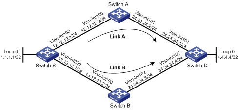
Network requirements
As shown in Figure 1, configure static route FRR to make sure when Link A fails, traffic can be switched to Link B immediately.
Requirements analysis
To make sure Switch S can switch traffic to Link B when Link A fails, configure a static route with next hop Switch B as a backup. Configure a lower priority for this static route than the priority for the static route with next hop Switch A so that Link A is preferred.
To make sure Switch S can immediately detect failures on the link between Switch S and Switch A, enable BFD on Switch S.
To make sure Link B takes effect immediately when Link A fails, enable FRR on Switch S by using a routing policy:
· To allow only matching packets to be switched to the backup link, specify an IP prefix list.
· To configure the backup static route for link switchover, specify both the output interface and next hop of the static route in the routing policy.
Configuration restrictions and guidelines
When you configure static route FRR, follow these restrictions and guidelines:
· FRR takes effect only for static routes with both the output interface and next hop specified. When you configure static routes, you must specify both the output interface and next hop for the static routes.
· Do not use static route FRR and static route BFD at the same time.
Software version used
This configuration example was created and verified on S12500-CMW520-R1825P01.
Configuration procedures
1. Configure IP addresses and subnet masks for interfaces on the switches, as shown in Figure 1. (Details not shown.)
2. Configure static routes on Switch S:
# Configure a static route with a higher priority.
[SwitchS] ip route-static 4.4.4.4 255.255.255.255 Vlan-interface100 12.12.12.2 preference 30
# Configure a static route with a lower priority to serve as a backup.
[SwitchS] ip route-static 4.4.4.4 255.255.255.255 Vlan-interface200 13.13.13.2 preference 40
3. Configure the source IP address of BFD echo packets and relevant BFD parameters.
[SwitchS] bfd echo-source-ip 67.67.67.67
[SwitchS] interface Vlan-interface100
[SwitchS-Vlan-interface100] bfd min-echo-receive-interval 10
[SwitchS-Vlan-interface100] bfd detect-multiplier 3
[SwitchS-Vlan-interface100] quit
4. Configure static route FRR:
# Configure an IPv4 prefix list.
[SwitchS] ip ip-prefix pf_frr index 10 permit 4.4.4.4 32
# Configure a routing policy.
[SwitchS] if-match ip-prefix pf_frr
[SwitchS-route-policy] if-match ip-prefix pf_frr
[SwitchS-route-policy] apply fast-reroute backup-interface Vlan-interface200 backup-nexthop 13.13.13.2
[SwitchS-route-policy] quit
# Enable static route FRR.
[SwitchS] ip route-static fast-reroute route-policy rp_frr
Verifying the configuration
# Display the detailed routing table information.
<SwitchS> display ip routing-table 4.4.4.4 32 verbose
Routing Table : Public
Summary Count : 2
Destination: 4.4.4.4/32
Protocol: Static Process ID: 0
Preference: 30 Cost: 0
NextHop: 12.12.12.2 Interface: Vlan-interface100
BkNextHop: 13.13.13.2 BkInterface: Vlan-interface200
RelyNextHop: 0.0.0.0 Neighbor : 0.0.0.0
Tunnel ID: 0x0 Label: NULL
State: Active Adv Age: 00h31m40s
Tag: 0
Destination: 4.4.4.4/32
Protocol: Static Process ID: 0
Preference: 40 Cost: 0
NextHop: 13.13.13.2 Interface: Vlan-interface200
BkNextHop: BkInterface:
RelyNextHop: 0.0.0.0 Neighbor : 0.0.0.0
Tunnel ID: 0x0 Label: NULL
State: Inactive Adv Age: 00h31m40s
Tag: 0
# Display the status of the BFD session automatically created by FRR.
<SwitchS> display bfd session verbose
Total Session Num: 1 Init Mode: Active
Session Working Under Echo Mode:
Local Discr: 1
Source IP: 12.12.12.1 Destination IP: 12.12.12.2
Session State: Up Interface: Vlan-interface100
Min Recv Inter: 10ms Act Trans Inter: 10ms
Act Detect Inter: 30ms Running Up for: 00:26:50
Connect Type: Direct Board Num: 0
Protocol: FRR
Diag Info: No Diagnostic
According to the location of the failure, FRR is implemented in the following ways:
· If the Layer 2 device or the link fails but the output interface is not down, BFD immediately detects the failure, and FRR performs a link switchover.
[SwitchS] display ip routing-table 4.4.4.4 32
Routing Table : Public
Summary Count : 1
Destination/Mask Proto Pre Cost NextHop Interface
4.4.4.4/32 Static 30 0 12.12.12.2 Vlan100
· If the output interface goes down, BFD detects the failure, and FRR performs a link switchover. The primary static route becomes inactive, and the backup static route is activated at the same time.
[SwitchS] display ip routing-table 4.4.4.4 32
Routing Table : Public
Summary Count : 1
Destination/Mask Proto Pre Cost NextHop Interface
4.4.4.4/32 Static 40 0 13.13.13.2 Vlan200
Configuration files
Switch S:
#
bfd echo-source-ip 67.67.67.67
#
vlan 100
#
vlan 200
#
interface Vlan-interface100
ip address 12.12.12.1 255.255.255.0
bfd min-echo-receive-interval 10
bfd detect-multiplier 3
#
interface Vlan-interface200
ip address 13.13.13.1 255.255.255.0
#
interface GigabitEthernet3/0/1
port link-mode bridge
port access vlan 100
#
interface GigabitEthernet3/0/2
port link-mode bridge
port access vlan 200
#
route-policy rp_frr permit node 10
if-match ip-prefix pf_frr
apply fast-reroute backup-interface Vlan-interface200 backup-nexthop 13.13.13.2
#
ip ip-prefix pf_frr index 10 permit 4.4.4.4 32
#
ip route-static fast-reroute route-policy rp_frr
#
ip route-static 4.4.4.4 255.255.255.255 Vlan-interface100 12.12.12.2 preference 30
ip route-static 4.4.4.4 255.255.255.255 Vlan-interface200 13.13.13.2 preference 40
#
Example: Configuring OSPF FRR
Network requirements
As shown in Figure 2, Switch S, Switch A, Switch B, and Switch D belong to the same OSPF domain.
Configure OSPF FRR to make sure when Link A fails, traffic can be switched to Link B immediately.
Requirements analysis
To make sure Link B is a backup for Link A, configure a greater cost for Link B.
To make sure Switch S can immediately detect failures on the link between Switch S and Switch A, enable BFD on Switch S.
To make sure Link B takes effect immediately when Link A fails, enable FRR on Switch S by using the fast-reroute auto command or by using a routing policy. When you enable OSPF FRR to designate a backup next hop by using a routing policy:
· To allow only matching packets to be switched to the backup link, specify an IP prefix list.
· To configure the backup route for link switchover, specify both the output interface and next hop of the route in the routing policy.
Software version used
This configuration example was created and verified on S12500-CMW520-R1825P01.
Configuration restrictions and guidelines
When you configure OSPF FRR, follow these restrictions and guidelines:
· Do not use OSPF FRR and OSPF BFD at the same time.
· Do not use the fast-reroute auto command together with the commands vlink-peer, sham-link, enable traffic-adjustment, and enable traffic-adjustment advertise.
Configuration procedures
1. Configure IP addresses for interfaces and enable OSPF on the switches:
# Configure the IP address and subnet mask for each interface, as shown in Figure 2. (Details not shown.)
# Configure OSPF on the switches to make sure Switch S, Switch A, Switch B, and Switch D can communicate with each other at the network layer and implement dynamic route update. (Details not shown.)
# Configure the OSPF cost for VLAN-interface 200 on Switch S as 3, so Link A is preferred by OSPF. (Details not shown.)
2. Configure the source IP address for BFD echo packets and relevant BFD parameters. ICMP redirection might be enabled on the peer device, so H3C recommends configuring an IP address that is not in use as the source IP address.
[SwitchS] bfd echo-source-ip 67.67.67.67
[SwitchS] interface Vlan-interface100
[SwitchS-Vlan-interface100] bfd min-echo-receive-interval 10
[SwitchS-Vlan-interface100] bfd detect-multiplier 3
[SwitchS-Vlan-interface100] quit
3. Configure OSPF FRR by using either of the following methods:
? (Method 1) Enable OSPF FRR to automatically calculate a backup next hop.
[SwitchS] ospf 1
[SwitchS-ospf-1] fast-reroute auto
[SwitchS-ospf-1] quit
? (Method 2) Enable OSPF FRR to designate a backup next hop by using a routing policy.
[SwitchS] ip ip-prefix pf_frr index 10 permit 4.4.4.4 32
[SwitchS] route-policy rp_frr permit node 10
[SwitchS-route-policy] if-match ip-prefix pf_frr
[SwitchS-route-policy] apply fast-reroute backup-interface Vlan-interface200 backup-nexthop 13.13.13.2
[SwitchS-route-policy] quit
[SwitchS] ospf 1
[SwitchS-ospf-1] fast-reroute route-policy rp_frr
[SwitchS-ospf-1] quit
Verifying the configuration
# Display the detailed routing table information.
<SwitchS> display ip routing-table 4.4.4.4 32 verbose
Routing Table : Public
Summary Count : 1
Destination: 4.4.4.4/32
Protocol: OSPF Process ID: 1
Preference: 10 Cost: 2
NextHop: 12.12.12.2 Interface: Vlan-interface100
BkNextHop: 13.13.13.2 BkInterface: Vlan-interface200
RelyNextHop: 0.0.0.0 Neighbor : 0.0.0.0
Tunnel ID: 0x0 Label: NULL
State: Active Adv Age: 00h37m45s
Tag: 0
# Display the status of the BFD session automatically created by FRR.
<SwitchS> display bfd session verbose
Total session number: 1 Up session number: 1 Init mode: Active
IPv4 session working under Echo mode:
Local Discr: 12
Source IP: 12.12.12.1 Destination IP: 12.12.12.2
Session State: Up Interface: Vlan-interface100
Min Recv Inter: 10ms Act Trans Inter: 10ms
Act Detect Inter: 30ms Running Up for: 00:42:20
Connect Type: Direct Board Num: 0
Protocol: FRR
Diag Info: No Diagnostic
When the link between Switch S and Switch A fails, BFD immediately detects the failure, and FRR performs a link switchover. The backup next hop is used to forward packets until OSPF completes route convergence, ensuring service continuity.
Configuration files
· Method 1:
#
bfd echo-source-ip 67.67.67.67
#
vlan 100
#
vlan 200
#
interface Vlan-interface100
ip address 12.12.12.1 255.255.255.0
bfd min-echo-receive-interval 10
bfd detect-multiplier 3
#
interface Vlan-interface200
ip address 13.13.13.1 255.255.255.0
ospf cost 3
#
interface GigabitEthernet3/0/1
port link-mode bridge
port access vlan 100
#
interface GigabitEthernet3/0/2
port link-mode bridge
port access vlan 200
#
ospf 1
fast-reroute auto
area 0.0.0.0
network 12.12.12.0 0.0.0.255
network 13.13.13.0 0.0.0.255
network 1.1.1.1 0.0.0.0
#
· Method 2:
#
bfd echo-source-ip 67.67.67.67
#
vlan 100
#
vlan 200
#
interface Vlan-interface100
ip address 12.12.12.1 255.255.255.0
bfd min-echo-receive-interval 10
bfd detect-multiplier 3
#
interface Vlan-interface200
ip address 13.13.13.1 255.255.255.0
ospf cost 3
#
interface GigabitEthernet3/0/1
port link-mode bridge
port access vlan 100
#
interface GigabitEthernet3/0/2
port link-mode bridge
port access vlan 200
#
ospf 1
fast-reroute route-policy rp_frr
area 0.0.0.0
network 12.12.12.0 0.0.0.255
network 13.13.13.0 0.0.0.255
network 1.1.1.1 0.0.0.0
#
route-policy rp_frr permit node 10
if-match ip-prefix pf_frr
apply fast-reroute backup-interface Vlan-interface200 backup-nexthop 13.13.13.2
#
ip ip-prefix pf_frr index 10 permit 4.4.4.4 32
#
Example: Configuring IS-IS FRR
Network requirements
As shown in Figure 3, Switch S, Switch A, Switch B, and Switch D belong to the same IS-IS routing domain.
Configure IS-IS FRR to make sure when Link A fails, traffic will be switched to Link B immediately.
Requirements analysis
To make sure Link B is a backup for Link A, configure a greater cost for Link B.
To make sure Switch S can immediately detect failures on the link between Switch S and Switch A, enable BFD on Switch S.
To make sure Link B takes effect immediately when Link A fails, enable FRR on Switch S by using the fast-reroute auto command or by using a routing policy. When you enable IS-IS FRR to designate a backup next hop by using a routing policy:
· To allow only matching packets to be switched to the backup link, specify an IP prefix list.
· To configure the backup route for link switchover, specify both the output interface and next hop of the route in the routing policy.
Software version used
This configuration example was created and verified on S12500-CMW520-R1825P01.
Configuration restrictions and guidelines
When you configure IS-IS FRR, follow these restrictions and guidelines:
· Do not use IS-IS FRR and IS-IS BFD at the same time.
· The automatic backup next hop calculation of IS-IS FRR and MPLS TE are mutually exclusive, which means the fast-reroute auto command and the traffic-eng command are mutually exclusive.
Configuration procedures
1. Configure IP addresses for interfaces and enable IS-IS on the switches:
# Configure the IP address and subnet mask for each interface, as shown in Figure 3. (Details not shown.)
# Configure IS-IS on the switches to make sure Switch S, Switch A, Switch B, and Switch D can communicate with each other at the network layer and implement dynamic route update. (Details not shown.)
# Configure the IS-IS cost for VLAN-interface 100 on Switch S as 10, and configure other interfaces to use the default value 20, so Link A is preferred by IS-IS. (Details not shown.)
2. Configure the source IP address for BFD echo packets and relevant BFD parameters. ICMP redirection might be enabled on the peer device, so H3C recommends configuring an IP address that is not in use as the source IP address.
[SwitchS] bfd echo-source-ip 67.67.67.67
[SwitchS] interface Vlan-interface100
[SwitchS-Vlan-interface100] bfd min-echo-receive-interval 10
[SwitchS-Vlan-interface100] bfd detect-multiplier 3
[SwitchS-Vlan-interface100] quit
3. Configure IS-IS FRR by using either of the following methods:
? (Method 1) Enable IS-IS FRR to automatically calculate a backup next hop.
[SwitchS] isis 1
[SwitchS-isis-1] fast-reroute auto
[SwitchS-isis-1] quit
? (Method 2) Enable IS-IS FRR to designate a backup next hop by using a routing policy.
[SwitchS] ip ip-prefix pf_frr index 10 permit 4.4.4.4 32
[SwitchS] route-policy rp_frr permit node 10
[SwitchS-route-policy] if-match ip-prefix pf_frr
[SwitchS-route-policy] apply fast-reroute backup-interface Vlan-interface200 backup-nexthop 13.13.13.2
[SwitchS-route-policy] quit
[SwitchS] isis 1
[SwitchS-isis-1] fast-reroute route-policy rp_frr
[SwitchS-isis-1] quit
Verifying the configuration
# Display the detailed routing table information.
<SwitchS> display ip routing-table 4.4.4.4 32 verbose
Routing Table : Public
Summary Count : 1
Destination: 4.4.4.4/32
Protocol: ISIS Process ID: 1
Preference: 15 Cost: 20
NextHop: 12.12.12.2 Interface: Vlan-interface100
BkNextHop: 13.13.13.2 BkInterface: Vlan-interface200
RelyNextHop: 0.0.0.0 Neighbor : 0.0.0.0
Tunnel ID: 0x0 Label: NULL
State: Active Adv Age: 00h36m27s
Tag: 0
# Display the status of the BFD session automatically created by FRR.
<SwitchS> display bfd session verbose
Total Session Num: 1 Init Mode: Active
Session Working Under Echo Mode:
Local Discr: 16
Source IP: 12.12.12.1 Destination IP: 12.12.12.2
Session State: Up Interface: Vlan-interface100
Min Recv Inter: 10ms Act Trans Inter: 10ms
Act Detect Inter: 30ms Running Up for: 00:39:05
Connect Type: Direct Board Num: 0
Protocol: FRR
Diag Info: No Diagnostic
When the link between Switch S and Switch A fails, BFD immediately detects the failure, and FRR performs a link switchover. The backup next hop is used to forward packets until IS-IS completes route convergence, ensuring service continuity.
Configuration files
· Method 1:
#
bfd echo-source-ip 67.67.67.67
#
vlan 100
#
vlan 200
#
isis 1
is-level level-2
fast-reroute auto
network-entity 00.0000.0000.0000.0001.00
#
interface Vlan-interface100
ip address 12.12.12.1 255.255.255.0
isis enable 1
isis cost 10
bfd min-echo-receive-interval 10
bfd detect-multiplier 3
#
interface Vlan-interface200
ip address 13.13.13.1 255.255.255.0
isis enable 1
isis cost 30
#
interface GigabitEthernet3/0/1
port link-mode bridge
port access vlan 100
#
interface GigabitEthernet3/0/2
port link-mode bridge
port access vlan 200
#
· Method 2:
#
bfd echo-source-ip 67.67.67.67
#
vlan 100
#
vlan 200
#
isis 1
is-level level-2
fast-reroute route-policy rp_frr
network-entity 00.0000.0000.0000.0001.00
#
interface Vlan-interface100
ip address 12.12.12.1 255.255.255.0
isis enable 1
isis cost 10
bfd min-echo-receive-interval 10
bfd detect-multiplier 3
#
interface Vlan-interface200
ip address 13.13.13.1 255.255.255.0
isis enable 1
isis cost 30
#
interface GigabitEthernet3/0/1
port link-mode bridge
port access vlan 100
#
interface GigabitEthernet3/0/2
port link-mode bridge
port access vlan 200
#
route-policy rp_frr permit node 10
if-match ip-prefix pf_frr
apply fast-reroute backup-interface Vlan-interface200 backup-nexthop 13.13.13.2
#
ip ip-prefix pf_frr index 10 permit 4.4.4.4 32
#
Example: Configuring RIP FRR
Network requirements
As shown in Figure 4, Switch S, Switch A, Switch B, and Switch D are interconnected through RIPv2.
Configure RIP FRR to make sure when Link A fails, traffic can be switched to Link B immediately.
Requirements analysis
To make sure Link B is a backup for Link A, configure a greater cost for Link B.
To make sure Switch S can immediately detect failures on the link between Switch S and Switch A, enable BFD on Switch S.
To make sure Link B takes effect immediately when Link A fails, enable FRR on Switch S by using a routing policy:
· To allow only matching packets to be switched to the backup link, specify an IP prefix list.
· To configure the backup static route for link switchover, specify both the output interface and next hop of the static route in the routing policy.
Software version used
This configuration example was created and verified on S12500-CMW520-R1825P01.
Configuration restrictions and guidelines
When you configure RIP FRR, follow these restrictions and guidelines:
· Do not use RIP FRR and RIP BFD at the same time.
· RIP FRR is only effective for non-recursive RIP routes that are learned from directly connected neighbors.
Configuration procedures
1. Configure IP addresses for interfaces and enable RIPv2 on the switches:
# Configure the IP address and subnet mask for each interface, as shown in Figure 4. (Details not shown.)
# Configure RIP on the switches to make sure Switch S, Switch A, Switch B, and Switch D can communicate with each other at the network layer and implement dynamic route update. (Details not shown.)
# On Switch S, configure the additional metric for RIP routes sent through VLAN-interface 200 as 2, so Link A is preferred by RIP. (Details not shown.)
2. Configure the source IP address for BFD echo packets and relevant BFD parameters. ICMP redirection might be enabled on the peer device, so H3C recommends configuring an IP address that is not in use as the source IP address.
[SwitchS] bfd echo-source-ip 67.67.67.67
[SwitchS] interface Vlan-interface100
[SwitchS-Vlan-interface100] bfd min-echo-receive-interval 10
[SwitchS-Vlan-interface100] bfd detect-multiplier 3
[SwitchS-Vlan-interface100] quit
3. Enable RIP FRR to designate a backup next hop by using a routing policy.
[SwitchS] ip ip-prefix pf_frr index 10 permit 4.4.4.4 32
[SwitchS] route-policy rp_frr permit node 10
[SwitchS-route-policy] if-match ip-prefix pf_frr
[SwitchS-route-policy] apply fast-reroute backup-interface Vlan-interface200 backup-nexthop 13.13.13.2
[SwitchS-route-policy] quit
[SwitchS] rip 1
[SwitchS-rip-1] fast-reroute route-policy rp_frr
[SwitchS-rip-1] quit
Verifying the configuration
# Display the detailed routing table information.
<SwitchS> display ip routing-table 4.4.4.4 32 verbose
Routing Table : Public
Summary Count : 1
Destination: 4.4.4.4/32
Protocol: RIP Process ID: 1
Preference: 100 Cost: 2
NextHop: 12.12.12.2 Interface: Vlan-interface100
BkNextHop: 13.13.13.2 BkInterface: Vlan-interface200
RelyNextHop: 0.0.0.0 Neighbor : 12.12.12.2
Tunnel ID: 0x0 Label: NULL
State: Active Adv Age: 00h25m59s
Tag: 0
# Display the status of the BFD session automatically created by FRR.
<SwitchS> display bfd session verbose
Total Session Num: 1 Init Mode: Active
Session Working Under Echo Mode:
Local Discr: 20
Source IP: 12.12.12.1 Destination IP: 12.12.12.2
Session State: Up Interface: Vlan-interface100
Min Recv Inter: 10ms Act Trans Inter: 10ms
Act Detect Inter: 30ms Running Up for: 00:26:18
Connect Type: Direct Board Num: 0
Protocol: FRR
Diag Info: No Diagnostic
When the link between Switch S and Switch A fails, BFD immediately detects the failure and FRR performs a link switchover. The new route is adopted by RIP.
Configuration files
#
bfd echo-source-ip 67.67.67.67
#
vlan 100
#
vlan 200
#
interface Vlan-interface100
ip address 12.12.12.1 255.255.255.0
bfd min-echo-receive-interval 10
bfd detect-multiplier 3
#
interface Vlan-interface200
ip address 13.13.13.1 255.255.255.0
rip metricin 5
#
interface GigabitEthernet3/0/1
port link-mode bridge
port access vlan 100
#
interface GigabitEthernet3/0/2
port link-mode bridge
port access vlan 200
#
rip 1
undo summary
version 2
network 12.0.0.0
network 13.0.0.0
fast-reroute route-policy rp_frr
#
route-policy rp_frr permit node 10
if-match ip-prefix pf_frr
apply fast-reroute backup-interface Vlan-interface200 backup-nexthop 13.13.13.2
#
ip ip-prefix pf_frr index 10 permit 4.4.4.4 32
#
Related documentation
· H3C S12500 Routing Switch Series Layer 3—IP Routing Configuration Guide
· H3C S12500 Routing Switch Series Layer 3—IP Routing Command Reference
· H3C S12500 Routing Switch Series High Availability Configuration Guide
· H3C S12500 Routing Switch Series High Availability Command Reference
