- Table of Contents
-
- 05-Layer 3 - IP Services Configuration Guide
- 00-Preface
- 01-ARP Configuration
- 02-IP Addressing Configuration
- 03-DHCP Configuration
- 04-DNS Configuration
- 05-NAT Configuration
- 06-IP Performance Optimization Configuration
- 07-Adjacency Table Configuration
- 08-UDP Helper Configuration
- 09-IPv6 Basics Configuration
- 10-DHCPv6 Configuration
- 11-IPv6 DNS Configuration
- 12-NAT-PT Configuration
- 13-Tunneling Configuration
- 14-GRE Configuration
- Related Documents
-
| Title | Size | Download |
|---|---|---|
| 14-GRE Configuration | 230.17 KB |
GRE overview
Generic Routing Encapsulation (GRE) is a tunneling protocol. It can encapsulate a wide variety of network layer protocol packet types inside IP tunnels.
A GER tunnel is a virtual point-to-point (P2P) connection. Packets are encapsulated at one end of the tunnel and de-encapsulated at the other end.
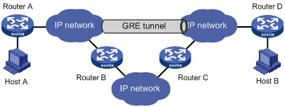
Figure 1 X protocol networks interconnected through the GRE tunnel
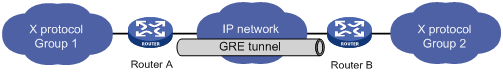
The following takes the network shown in Figure 1 as an example to describe how an X protocol packet traverses the IP network through a GRE tunnel.
Encapsulation process
1. After receiving an X protocol packet from the interface connected to Group 1, Router A submits it to the X protocol for processing.
2. The X protocol checks the destination address field in the packet header to determine how to route the packet.
3. If the packet must be tunneled to reach its destination, Router A sends it to the tunnel interface.
4. Upon receipt of the packet, the tunnel interface encapsulates it in a GRE packet. Then, the system encapsulates the packet in an IP packet and forwards the IP packet based on its destination address and the routing table.
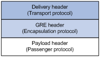
GRE encapsulation format
Figure 2 GRE encapsulation format
As an example, Figure 3 shows the format of an X protocol packet encapsulated for transmission over an IP tunnel.
Figure 3 Format of an X packet encapsulated for transmission over an IP tunnel
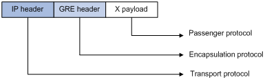
· Payload—Packet that needs to be encapsulated and transmitted.
· Passenger protocol—Protocol that the payload packet uses, X in the example.
· Encapsulation or carrier protocol—Protocol used to encapsulate the payload packet, that is, GRE.
· Delivery or transport protocol—Protocol used to encapsulate the GRE packet and to forward the resulting packet to the other end of the tunnel, IP in this example.
Depending on the transport protocol, two tunnel modes are present: GRE over IPv4 and GRE over IPv6.
De-encapsulation process
De-encapsulation is the reverse of the encapsulation process:
1. Upon receiving an IP packet from the tunnel interface, Router B checks the destination address.
2. If the destination is itself and the protocol number in the IP header is 47 (the protocol number for GRE), Router B strips off the IP header of the packet and submits the resulting packet to the GRE protocol.
3. The GRE protocol checks the key, checksum and sequence number in the packet, and then strips off the GRE header and submits the payload to the X protocol for forwarding.
|
|
NOTE: Encapsulation and de-encapsulation processes on both ends of the GRE tunnel and the resulting increase in data volumes will degrade the forwarding efficiency of a GRE-enabled router to some extent. |
GRE applications
Multi-protocol communications through a single-protocol backbone
Figure 4 Multi-protocol communications through a single-protocol backbone
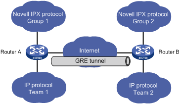
In the example as shown in Figure 4, Group 1 and Group 2 are local networks running Novell IPX, while Team 1 and Team 2 are local networks running IP. Through the GRE tunnel between Router A and Router B, Group 1 can communicate with Group 2 and Team 1 can communicate with Team 2. They will not interfere with each other.
Scope enlargement of a hop-limited protocol such as RIP
Figure 5 Network scope enlargement
When the hop count between two terminals exceeds 15, the terminals cannot communicate with each other. Using GRE, you can hide some hops so as to enlarge the scope of the network.
VPN creation by connecting discontinuous subnets
Figure 6 Connect discontinuous subnets with a tunnel to form a VPN
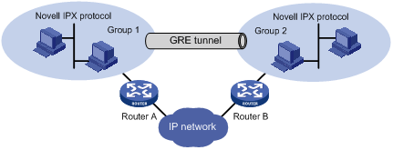
In the example as shown in Figure 6, Group 1 and Group 2 running Novell IPX are deployed in different cities. They can constitute a trans-WAN virtual private network (VPN) through the tunnel.
|
|
NOTE: The router does not support Novell IPX networks. |
Protocols and standards
· RFC 1701, Generic Routing Encapsulation (GRE)
· RFC 1702, Generic Routing Encapsulation over IPv4 Networks
· RFC 2784, Generic Routing Encapsulation (GRE)
Configuring a GRE tunnel
Configuration prerequisites
Interfaces on a router, such as VLAN interfaces and GigabitEthernet interfaces, are configured with IPv4 addresses and can communicate. These interfaces can be used as the source of a virtual tunnel interface to ensure the reachability of the tunnel destination address.
Configuration guidelines
· The source address and destination address of a tunnel uniquely identify a path. They must be configured at both ends of the tunnel and the source address at one end must be the destination address at the other end and vice versa.
· Tunnel interfaces using the same encapsulation protocol must have different source addresses and destination addresses.
· If you configure a source interface for a tunnel interface, the tunnel interface takes the primary IP address of the source interface as its source address.
· When configuring a route through the tunnel, you are not allowed to set up a static route whose destination address is in the subnet of the tunnel interface. Instead, you can do one of the following:
? Configure a static route, using the address of the network segment that the original packet is destined for as its destination address and the address of the peer tunnel interface as its next hop.
? Enable a dynamic routing protocol on both the tunnel interface and the router interface connecting the private network, so that the dynamic routing protocol can establish a routing entry to forward packets through the tunnel.
Configuration procedure
To configure a GRE tunnel:
|
Step |
Command |
Remarks |
|
1. Enter system view. |
system-view |
N/A |
|
2. Enable the IPv6 packet forwarding function. |
ipv6 |
Optional. Disabled by default. The function is required for IPv6 over IPv4 GRE tunnels. |
|
3. Create a tunnel interface and enter tunnel interface view. |
interface tunnel interface-number |
Not created by default. |
|
4. Configure an IPv4 address, an IPv6 global unicast address, or a site local address for the tunnel interface. |
·
To configure an IPv4 address: ·
To configure an IPv6 global unicast address: ·
To configure a site local address: |
Configure one as needed. By default, a tunnel interface is not configured with any IPv4 address, IPv6 global unicast address, or site local address. |
|
5. Configure an IPv6 link local address for the tunnel interface. |
· To automatically generate a link-local address: · Configure a link-local address manually: |
Optional. By default, if an interface is configured with an IPv6 global unicast address or site local address, a link local address will be automatically created. |
|
6. Set the tunnel mode to GRE. |
tunnel-protocol gre |
Optional. GRE by default. You must configure the same tunnel mode on both ends of a tunnel. Otherwise, packet delivery will fail. |
|
7. Configure the source address or interface for the tunnel interface. |
source { ip-address | interface-type interface-number } |
By default, no source address or interface is configured for a tunnel interface. |
|
8. Configure the destination address for the tunnel interface. |
destination ip-address |
By default, no destination address is configured for a tunnel interface. |
|
9. Configure a route through the tunnel. |
See Layer 3—IP Routing Configuration Guide. |
Optional. Each end of the tunnel must have a route (static or dynamic) through the tunnel to the other end. |
|
10. Set the MTU value for the tunnel interface. |
· mtu mtu-size · ipv6 mtu mtu-size |
Optional. Configure one command as needed. |
|
11. Return to system view. |
quit |
N/A |
|
12. Configure the router to discard IPv4-compatible IPv6 packets. |
tunnel discard ipv4-compatible-packet |
Optional. By default, the router does not discard the IPv4-compatible IPv6 packets. |
|
|
NOTE: For information about commands interface tunnel, source, destination, and mtu, see Layer 3—IP Services Command Reference. |
Displaying and maintaining GRE
|
Task |
Command |
Remarks |
|
Display information about a specific or all tunnel interfaces. |
display interface [ tunnel ] [ brief [ down ] ] [ | { begin | exclude | include } regular-expression ] display interface tunnel number [ brief ] [ | { begin | exclude | include } regular-expression ] |
Available in any view |
|
Display IPv6 information about a tunnel interface. |
display ipv6 interface tunnel [ number ] [ verbose ] [ | { begin | exclude | include } regular-expression ] |
Available in any view |
|
|
NOTE: For information about commands display interface tunnel and display ipv6 interface tunnel, see Layer 3—IP Services Command Reference. |
GRE tunnel configuration example
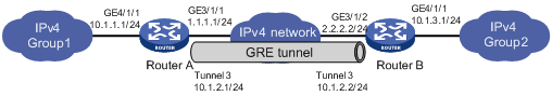
Network requirements
As shown in Figure 7, Router A and Router B are interconnected through the Internet. Two private IPv4 subnets Group 1 and Group 2 are interconnected through a GRE tunnel between the two routers.
Configuration procedure
|
|
NOTE: Before performing GRE tunnel configuration, configure the interfaces connected to the Internet on Router A and Router B and configure routing protocols, so that a route is available between the two routers. |
1. Configure Router A.
# Configure an IPv4 address for interface GigabitEthernet 4/1/1.
<RouterA> system-view
[RouterA] interface GigabitEthernet 4/1/1
[RouterA-GigabitEthernet4/1/1] ip address 10.1.1.1 255.255.255.0
[RouterA-GigabitEthernet4/1/1] quit
# Configure an IPv4 address for interface GigabitEthernet 3/1/1, the physical interface of the tunnel.
[RouterA] interface GigabitEthernet 3/1/1
[RouterA-GigabitEthernet3/1/1] ip address 1.1.1.1 255.255.255.0
[RouterA-GigabitEthernet3/1/1] quit
# Create a tunnel interface named Tunnel3.
[RouterA] interface tunnel 3
# Configure an IPv4 address for the tunnel interface Tunnel3.
[RouterA-Tunnel3] ip address 10.1.2.1 255.255.255.0
# Configure the tunnel encapsulation mode.
[RouterA-Tunnel3] tunnel-protocol gre
# Configure the source address of the tunnel interface Tunnel3 as the IP address of GigabitEthernet 3/1/1.
[RouterA-Tunnel3] source 1.1.1.1
# Configure the destination address of the tunnel interface Tunnel3 as the IP address of GigabitEthernet 3/1/2 on Router B.
[RouterA-Tunnel3] destination 2.2.2.2
[RouterA-Tunnel3] quit
# Configure a static route from Router A through the tunnel interface Tunnel3 to Group 2.
[RouterA] ip route-static 10.1.3.0 255.255.255.0 tunnel 3
2. Configure Router B.
# Configure an IPv4 address for interface GigabitEthernet 4/1/1.
<RouterB> system-view
[RouterB] interface GigabitEthernet 4/1/1
[RouterB-GigabitEthernet4/1/1] ip address 10.1.3.1 255.255.255.0
[RouterB-GigabitEthernet4/1/1] quit
# Configure an IPv4 address for interface GigabitEthernet 3/1/2, the physical interface of the tunnel.
[RouterB] interface GigabitEthernet 3/1/2
[RouterB-GigabitEthernet3/1/2] ip address 2.2.2.2 255.255.255.0
[RouterB-GigabitEthernet3/1/2] quit
# Create an interface named Tunnel 3.
[RouterB] interface tunnel 3
# Configure an IP address for the tunnel interface Tunnel3.
[RouterB-Tunnel3] ip address 10.1.2.2 255.255.255.0
# Configure the tunnel encapsulation mode.
[RouterB-Tunnel3] tunnel-protocol gre
# Configure the source address of the tunnel interface Tunnel3 to be the IP address of interface GigabitEthernet 3/1/2.
[RouterB-Tunnel3] source 2.2.2.2
# Configure the destination address of the tunnel interface Tunnel3 as the IP address of interface GigabitEthernet 3/1/1 on Router A.
[RouterB-Tunnel3] destination 1.1.1.1
[RouterB-Tunnel3] quit
# Configure a static route from Router B through interface Tunnel3 to Group 1.
[RouterB] ip route-static 10.1.1.0 255.255.255.0 tunnel 3
Troubleshooting GRE
The GRE configurations are relatively simple. The key is to keep the configurations consistent. Most faults can be located by using debugging commands. This section analyzes only one type of fault, as shown in Figure 8.
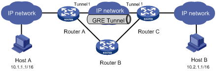
Symptom: The interfaces at both ends of the tunnel are configured correctly and can ping each other, but Host A and Host B cannot ping each other.
Solution:
· On Router A and Router C, execute the display ip routing-table command in any view respectively. On Router A, observe whether there is a route from Router A through Tunnel 1 to 10.2.0.0/16. On Router C, observe whether there is a route from Router C through Tunnel 1 to 10.1.0.0/16.
· For any missing static routes, use the ip route-static command in system view to configure. For example, configure a static route on Router A as follows:
[RouterA] ip route-static 10.2.0.0 255.255.0.0 tunnel 1
