- Table of Contents
- Related Documents
-
| Title | Size | Download |
|---|---|---|
| 03-VPLS Configuration | 539.08 KB |
Contents
Configuring an LDP VPLS instance
Configuring a BGP VPLS instance
Resetting VPLS BGP connections
Binding a Layer 3 interface with a VPLS instance
Binding a service instance with a VPLS instance
Configuring VPLS and MAC-in-MAC dual-stack support
Configuring MAC address learning
Configuring VPLS instance attributes
Configuring traffic policing for an AC
Displaying and maintaining VPLS
Configuring H-VPLS with LSP access
Configuring PW redundancy for H-VPLS access
Configuring BFD for the main link in an H-VPLS network
Implementing multi-AS VPN through multi-hop PW
VPLS and MAC-in-MAC dual-stack support configuration example
|
|
NOTE: · The switch operates in IRF or standalone (the default) mode. For more information about IRF mode, see IRF Configuration Guide. · The switch does not support VPLS when the system works in normal mode. For more information about system working modes, see Fundamentals Configuration Guide. |
VPLS overview
Virtual Private LAN Service (VPLS), also called “Transparent LAN Service (TLS)” or “virtual private switched network service”, can deliver a point-to-multipoint L2VPN service over public networks. With VPLS, geographically-dispersed sites can interconnect and communicate over MAN or WAN as if they were on the same LAN.
VPLS provides Layer 2 VPN services. However, it supports multipoint services, rather than the point-to-point services that traditional VPN supports. With VPLS, service providers can create on the PEs a series of virtual switches for customers, allowing customers to build their LANs across the Metropolitan Area Network (MAN) or Wide Area Network (WAN).
Operation of VPLS
Basic VPLS concepts
· CE—Customer edge device that is directly connected to the service provider network.
· PE—Provider edge device that connects one or more CEs to the service provider network. A PE maps and forwards packets between private networks and public network tunnels. A PE can be a UPE or NPE.
· UPE—User facing provider edge device that functions as the user access convergence device.
· NPE—Network provider edge device that functions as the network core PE. An NPE resides at the edge of a VPLS network core domain and provides transparent VPLS transport services between core networks.
· VSI—Virtual switch instance that maps actual access links to virtual links.
· PW—Pseudo wire, a bidirectional virtual connection between VSIs. A PW consists of two unidirectional MPLS virtual circuits (VCs).
· AC—Attachment circuit that connects the CE to the PE. It can use physical interfaces or virtual interfaces. Usually, all user packets on an AC, including Layer 2 and Layer 3 protocol messages, must be forwarded to the peer site without being changed.
· QinQ—802.1Q in 802.1Q, a tunneling protocol based on 802.1Q. It offers a point-to-multipoint L2VPN service mechanism. With QinQ, the private network VLAN tags of packets are encapsulated into the public network VLAN tags, allowing packets to be transmitted with two layers of tags across the service provider network. This provides a simpler Layer 2 VPN tunneling service.
· Forwarders—A forwarder functions as the VPLS forwarding table. Once a PE receives a packet from an AC, the forwarder selects a PW for forwarding the packet.
· Tunnel—A tunnel, usually an MPLS tunnel, is a direct channel between a local PE and the peer PE for transparent data transmission in-between. It is used to carry PWs. A tunnel can carry multiple PWs.
· Encapsulation—Packets transmitted over a PW use the standard PW encapsulation formats and technologies: Ethernet and VLAN.
· PW signaling—The PW signaling protocol is the fundament of VPLS. It is used for creating and maintaining PWs and automatically discovering VSI peer PEs. Two PW signaling protocols are available: LDP and BGP.
· QoS—Quality of Service (QoS) is implemented by mapping the preference information in the packet header to the QoS preference information transferred on the public network.
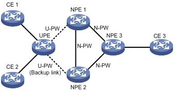
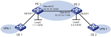
Figure 1 shows a typical VPLS networking scenario.
Figure 1 Network diagram for VPLS
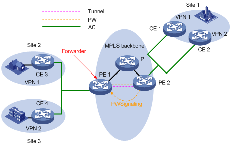
|
|
CAUTION: Do not enable STP or configure RRPP at the private network side of the PEs. Otherwise, a broadcast storm will occur, crashing down the network. For more information about STP, see Layer 2—LAN Switching Configuration Guide. For more information about RRPP, see High Availability Configuration Guide. |
MAC address learning and flooding
VPLS provides reachability by MAC address learning. Each PE maintains a MAC address table.
· Source MAC address learning
MAC address learning includes the following parts:
¡ Remote MAC address learning associated with PWs
A PW consists of two unidirectional VC LSPs. A PW is up only when both of the VC LSPs are up. When the inbound VC LSP learns a new MAC address, the PW needs to map the MAC address to the outbound VC LSP.
¡ Local MAC address learning of interfaces directly connected to users
This refers to learning source MAC addresses from Layer 2 packets originated by CEs. This occurs on the corresponding VSI interfaces.
Figure 2 shows the procedure of MAC address learning and flooding on PEs.
Figure 2 MAC learning and flooding on PEs
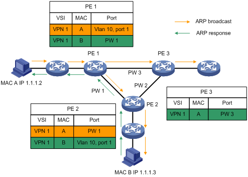
· MAC address reclaim
Dynamic address learning must support refreshing and relearning. The VPLS draft defines a dynamic address learning method that uses the address reclaim message, which carries MAC TLV. Upon receiving such a message, a device removes MAC addresses or relearns them according to the specified parameters in the TLV. If NULL is specified, the device removes all MAC addresses of the VSI except for those learned from the PW that received the address reclaim message.
The address reclaim message is very useful when the network topology changes and you must remove the learned MAC addresses quickly. There are two types of address reclaim messages: those with MAC address lists and those without MAC address lists.
After a backup link becomes active and a message with the instruction of relearning MAC entries arrives, a PE updates the corresponding MAC entries in the FIB table of the VPLS instance and sends the message to other PEs that are directly connected through LDP sessions. If the message contains a null MAC address TLV list, these PEs remove all MAC addresses from the specified VSI, except for those learned from the PW that sent the message.
· MAC address aging
Remote MAC addresses learned by a PE that are related to VC labels but no more in use need to be aged out by an aging mechanism. The aging mechanism used here is the aging timer corresponding to the MAC address. When receiving a packet whose source MAC address has an aging timer started, the PE resets the aging timer.
VPLS loop avoidance
To avoid loops in a VPLS network, full mesh and split horizon forwarding are used instead of STP at the private network side.
· Full mesh—PEs are logically fully meshed (so are PWs). Each PE must create for each VPLS forwarding instance a tree to all the other PEs of the instance.
· Split horizon forwarding—Each PE must support horizontal split to avoid loops. A PE cannot forward packets through PWs of the same VSI, because all the PEs of a VSI are directly connected. Packets from PWs on the public network side cannot be forwarded to other PWs; they can only be forwarded to the private network side.
Peer PE discovery and PW signaling protocol
For PEs in the same VSI, you can configure the peer PE addresses or use an automatic discovery mechanism. LDP and BGP are used to automatically discover VSI peer PEs.
For a PW to be created, a PW signaling protocol is needed to assign a multiplex distinguishing flag (or, VC label) and advertise the assigned VC flag to the peer. In addition, the PW signaling protocol advertises VPLS system parameters such as PW ID, control word, and interface parameters. With the PW signaling protocol, PWs can be established between PEs to form a fully meshed network to provide VPLS services. LDP and BGP can be used as PW signaling protocols.
VPLS can be one of the following based on the PW signaling protocol used:
· LDP VPLS—Uses LDP as the signaling protocol. This mode is also called the “Martini mode”.
· BGP VPLS—Uses BGP extension as the signaling protocol. This mode is also called the “Kompella mode”.
|
|
NOTE: For more information about the Martini mode, see the chapter “Configuring MPLS L2VPN.” |
VPLS packet encapsulation
Packet encapsulation on an AC
The packet encapsulation type of an AC depends on the user VSI access mode, which can be VLAN or Ethernet.
· VLAN access—The Ethernet header of a packet sent by a CE to a PE or sent by a PE to a CE includes a VLAN tag that is added in the header as a service delimiter for the service provider network to identify the user. The tag is called a “P-Tag”.
· Ethernet access—The Ethernet header of a packet upstream from the CE or downstream from the PE does not contain any service delimiter. If a header contains a VLAN tag, it is the internal VLAN tag of the user and means nothing to the PE. This kind of internal VLAN tag of the user is called a “U-Tag”.
You can specify the VSI access mode to be used.
Packet encapsulation on a PW
The packet encapsulation type of a PW, also called the “PW transport mode”, can be either Ethernet or VLAN.
· In Ethernet mode, P-Tag is not transferred on the PW. For a packet from a CE, if it contains the service delimiter, the PE removes the service delimiter and adds a PW label and a tunnel label into the packet before forwarding the packet. Otherwise, the PE adds a PW label and a tunnel label into the packet and then forwards the packet. For a packet to be sent downstream, whether the PE adds the service delimiter into the packet depends on your configuration. However, rewriting and removing of existing tags are not allowed.
· In VLAN mode, packets transmitted over the PW must carry a P-Tag. For a packet from a CE, if it contains the service delimiter, the PE keeps the P-Tag unchanged or changes the P-Tag to the VLAN tag expected by the peer PE or to a null tag (the tag value is 0), and then adds a PW label and a tunnel label into the packet before sending the packet out. If the packet contains no service delimiter, the PE adds the VLAN tag expected by the peer PE or a null tag, and then a PW label and a tunnel label into the packet before sending the packet out. For a packet to be sent downstream, the PE rewrites, removes, or retains the service delimiter depending on your configuration.
According to the protocol, the packet encapsulation type of a PW is VLAN by default.
H-VPLS implementation
Hierarchy of VPLS (H-VPLS) can extend the VPLS access range of a service provider and reduce costs.
H-VPLS access has the following advantages:
· H-VPLS has lower requirements on the multi-tenant unit switch (MTU-s). It has distinct hierarchies which fulfill definite tasks.
· H-VPLS reduces the logical complexity of the fully meshed network consisting of PEs and the configuration complexity.
The H-VPLS access modes include LSP access and QinQ access.
H-VPLS with LSP access
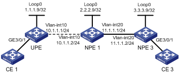
Figure 3 H-VPLS with LSP access
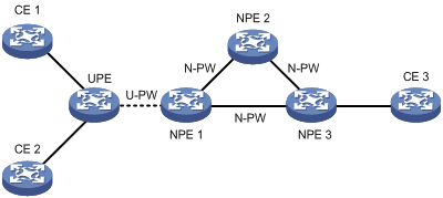
As shown in Figure 3, UPE functions as the convergence device MTU-s and establishes only a virtual link U-PW with NPE 1. It does not establish virtual links with any other peers.
Data forwarding in H-VPLS with LSP access is as follows:
· Upon receiving a packet from a CE, UPE tags the packet with the MPLS label for the U-PW, namely “the multiplex distinguishing flag”, and then sends the packet to NPE 1.
· When receiving the packet, NPE 1 determines which VSI the packet belongs to by the label and, based on the destination MAC address of the packet, tags the packet with the multiplex distinguishing flag for the N-PW, and forwards the packet.
· Upon receiving the packet from the N-PW, NPE 1 tags the packet with the multiplex distinguishing flag for the U-PW and sends the packet to UPE, which forwards the packet to the CE.
For packets to be exchanged between CE 1 and CE 2, UPE can forward them directly without NPE 1 because it holds the bridging function by itself. For the first packet with an unknown destination MAC address or a broadcast packet, UPE broadcasts the packet to CE 2 through the bridging function and, at the same time, forwards it through U-PW to NPE 1, which replicates the packet and sends a copy to each peer CE.
H-VPLS with QinQ access
Figure 4 H-VPLS with QinQ access
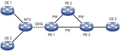
As shown in Figure 4, MTU is a standard bridging device and QinQ is enabled on its interfaces connected to CEs.
Data forwarding in H-VPLS with QinQ access is as follows:
· Upon receiving a packet from a CE, MTU labels the packet with a VLAN tag as the multiplex distinguishing flag, and transparently sends the packet to PE 1 through the QinQ tunnel.
· When receiving the packet, PE 1 determines which VSI the packet belongs to by the VLAN tag and, based on the destination MAC address of the packet, tags the packet with the multiplex distinguishing flag (MPLS label) for the PW. Then, it forwards the packet.
· Upon receiving the packet from the PW, PE 1 determines to which VSI the packet belongs by the multiplex distinguishing flag (MPLS label) and, based on the destination MAC address of the packet, labels the packet with the VLAN tag. Then, it forwards the packet through the QinQ tunnel to MTU, which in turn forwards the packet to the CE.
For packets to be exchanged between CE 1 and CE 2, MTU can forward them directly without PE 1 because it holds the bridging function by itself. For the first data packet with an unknown destination MAC address or a broadcast packet, MTU broadcasts the packet to CE 2 through the bridging function and, at the same time, forwards it through the QinQ tunnel to PE 1, which replicates the packet and sends a copy to each peer CE.
PW switchover
The network design with a single PW between a UPE and an NPE has a distinct drawback: once the PW experiences a failure, all VPNs connected to the aggregate device will lose connectivity. The H-VPLS with LSP access provides redundant links for PW backup. Normally, only the primary PW link is used. When the main link fails, the backup link will take over the VPN services, as shown in Figure 5.
Figure 5 Backup link for H-VPLS with LSP access
The H-VPLS with LSP access activates the backup link when:
· The tunnel over which the primary PW is established is deleted, causing the PW to go down.
· BFD detects a main link failure.
· The LDP session between the peers of the primary PW goes down, and the PW is deleted as a result.
Hub-spoke VPLS implementation
In hub-spoke networking, one of the VPLS networking modes, there is one hub site and multiple spoke sites. The spoke sites (the spoke-CEs) are not permitted to communicate with each other directly; data transmission between them depends on the hub site (the hub-CE). The PE connecting the hub site is called the “hub-PE”. PEs connecting the spoke sites are called “spoke-PEs”.
Advantages of hub-spoke networking
In hub-spoke networking, all traffic between spoke sites must go through the hub site, facilitating centralized management of traffic.
Hub-Spoke networking
Figure 6 Hub-spoke networking
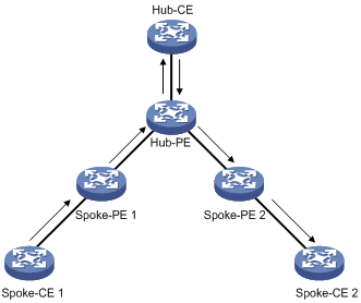
Figure 6 shows a typical hub-spoke networking application. As the MAC address learning in a hub-spoke network is the same as that in a common network, the following describes only the data forwarding procedure:
1. Upon receiving a packet from Spoke-CE 1, Spoke-PE 1 inserts an MPLS label into the packet according to the VSI to which Spoke-CE 1 belongs and then forwards the packet to Hub-PE.
2. Receiving the packet from the PW, Hub-PE determines by the MPLS label the VSI that the packet is for and forwards the packet to Hub-CE directly.
3. Hub-CE has Layer 2 forwarding function. It processes the packet and then forwards the packet back to Hub-PE.
4. Receiving the packet from the AC, Hub-PE determines by the VLAN tag the VSI that the packet is for, inserts an MPLS label to which the PW corresponds based on the destination MAC address, and forwards the packet to Spoke-PE 2.
5. When Spoke-PE 2 receives the packet from the PW, it determines by the MPLS label the VSI that the packet is for, and then forwards the packet to Spoke-CE 2.
|
|
NOTE: In a hub-spoke network, you can configure only one hub-CE node. |
Multi-hop PW
A PW cannot be setup directly between two PEs when:
· The two PEs are in different Autonomous Systems (ASs), where they cannot establish a singling connection.
· The two PEs use different PW signaling protocols.
In such cases, you can establish multiple continuous PW segments that function as a single PW, called a “multi-hop PW”, a virtual connection between the two PEs.
Figure 7 Diagram for multi-hop PW
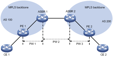
As shown in Figure 7, PE 1 and PE 2 are in different ASs. To set up a multi-hop PW between PE 1 and PE 2, you need to:
· Establish three PWs: PW 1 between PE 1 and ASBR 1, PW 2 between ASBR 1 and ASBR 2, and PW 3 between ASBR 2 between PE 2.
· Associate PW 1 and PW 2 on ASBR 1. Then, when receiving a packet from PW 1 (or PW 2), ASBR 1 removes the existing inner and outer labels of the packet and adds the inner and outer labels of PW 2 (or PW 1) to the packet.
· Associate PW 2 and PW 3 on ASBR 2. Then, upon receiving a packet from PW 2 (or PW 3), ASBR 2 removes the existing inner and outer labels of the packet and then adds the inner and outer labels of PW 3 (or PW 2) to the packet.
Thus, PW 1, PW 2, and PW 3 are put end to end and a multi-hop PW is formed across the ASs.
|
|
NOTE: Only LDP VPLS connections can form a multi-hop PW. |
VPLS configuration task list
Complete the following tasks to configure VPLS:
|
Task |
Remarks |
|
Configure either type of VPLS as needed |
|
|
Required |
|
|
Optional |
|
|
Optional |
|
|
Required |
|
|
Optional |
|
|
Required |
|
|
NOTE: When STP is enabled globally, the switch cannot transmit STP’s Bridge Protocol Data Units (BPDUs) on a VPLS PW. |
Enabling L2VPN and MPLS L2VPN
Enable L2VPN and MPLS L2VPN before you perform VPLS related configurations.
To enable L2VPN and MPLS L2VPN:
|
Step |
Command |
|
1. Enter system view. |
system-view |
|
2. Enable L2VPN and enter L2VPN view. |
l2vpn |
|
3. Enable MPLS L2VPN. |
mpls l2vpn |
|
|
NOTE: For detailed information about the l2vpn command and the mpls l2vpn command, see MPLS Command Reference. |
Configuring LDP VPLS
Configuration prerequisites
Before you configure LDP VPLS, complete the following tasks:
· Configure an IGP on the MPLS backbone devices (PEs and P devices) to guarantee the IP connectivity of the MPLS backbone. For configuration information, see Layer 3—IP Routing Configuration Guide.
· Configure basic MPLS on the MPLS backbone devices (PEs and P devices) to establish LSP tunnels on the backbone network. For configuration information, see the chapter “Configuring basic MPLS.”
· Configure LDP remote peers on PEs to establish remote LDP sessions. For configuration information, see the chapter “Configuring basic MPLS.”
Configuring an LDP VPLS instance
When creating an LDP VPLS instance, perform the following configurations:
1. Specify a globally unique name for the VPLS instance and set the peer discovery mechanism to manual configuration.
2. Configure LDP as the signaling protocol to be used.
3. Specify the ID of the VPLS instance.
4. Use the peer command to create the VPLS peer PE for the instance, specifying the following:
¡ IP address of the peer PE.
¡ ID of the PW to the peer PE, which must be consistent with that specified on the peer PE.
¡ Type of the peer PE. If you specify a peer as a UPE, the peer is a user access convergence device in the H-VPLS model. If you specify the backup-peer keyword when creating the peer, the local PE is a UPE and you create a primary NPE and a secondary NPE on it. On a UPE, you can configure only one pair of primary and secondary NPEs. The specified remote NPE peers must be fully meshed, but it is not necessary for a UPE to connect with all the NPEs.
¡ PW class template to be referenced. A PW class template defines the PW transport mode and tunneling policy to be used.
To configure an LDP VPLS instance:
|
Step |
Command |
Remarks |
|
1. Enter system view. |
system-view |
N/A |
|
2. Create a PW class template and enter its view. |
pw-class pw-class-name |
Optional. By default, no PW class template is created. |
|
3. Configure the PW transport mode. |
trans-mode { ethernet | vlan } |
Optional. VLAN by default. |
|
4. Specify a tunneling policy. |
pw-tunnel-policy policy-name |
Optional. By default, the tunneling policy specified through the tnl-policy command in VSI view is used. For how to configure a tunneling policy, see the chapter “Configuring MPLS L3VPN.” |
|
5. Return to system view. |
quit |
N/A |
|
6. Create an LDP VPLS instance and enter VSI view. |
vsi vsi-name static [ hub-spoke | p2p ] |
N/A |
|
7. Specify LDP as the PW signaling protocol and enter VSI LDP view. |
pwsignal ldp |
N/A |
|
8. Specify an ID for the VPLS instance. |
vsi-id vsi-id |
N/A |
|
9. Create a peer PE for the VPLS instance. |
peer ip-address [ { hub | spoke } | pw-class class-name | [ pw-id pw-id ] [ upe | backup-peer ip-address [ backup-pw-id pw-id ] ] ] * |
N/A |
|
10. Enable the PW switchover function and set the switchover delay time. |
dual-npe revertive [ wtr-time wtr-time ] |
Optional. Disabled by default. |
|
|
NOTE: · A PW to PW (P2P) mode VSI is applicable only to point to point MPLS L2VPN. · To configure a multi-hop PW, specify the p2p keyword when you create a VPLS instance to enable the P2P capability, and specify the two peer PEs by using the peer command in the VPLS instance view to associate two PWs. · Up to two peer PEs can be specified for a P2P enabled VPLS instance, and one of them must be specified as a UPE. |
Configuring BGP VPLS
Configuration prerequisites
Before you configure BGP VPLS, complete the following tasks:
· Configure an IGP on the MPLS backbone devices (PEs and P devices) to guarantee the IP connectivity of the MPLS backbone. For configuration information, see Layer 3—IP Routing Configuration Guide.
· Configure basic MPLS on the MPLS backbone devices (PEs and P devices) to establish LSP tunnels on the backbone network. For configuration information, see the chapter “Configuring basic MPLS.”
Configuring the BGP extension
Before configuring BGP VPLS, you need to configure BGP parameters on the PEs. For configuration details, see Layer 3—IP Routing Configuration Guide.
To configure BGP extension:
|
Step |
Command |
Remarks |
|
1. Enter system view. |
system-view |
N/A |
|
2. Enter BGP view. |
bgp as-number |
N/A |
|
3. Enter VPLS address family view. |
vpls-family |
N/A |
|
4. Activate a peer. |
peer peer-address enable |
No peer is activated by default. |
|
|
NOTE: For configurations in VPLS address family view, see the chapter “Configuring MPLS L3VPN.” |
Configuring a BGP VPLS instance
When creating a BGP VPLS instance, you must specify a globally unique name for the VPLS instance and set the peer discovery mechanism to automatic configuration.
When configuring a BGP VPLS instance, you must configure BGP as the signaling protocol to be used.
To configure a BGP VPLS instance:
|
Step |
Command |
|
1. Enter system view. |
system-view |
|
2. Create a BGP VPLS instance and enter VSI view. |
vsi vsi-name auto |
|
3. Specify BGP as the PW signaling protocol and enter VSI BGP view. |
pwsignal bgp |
|
4. Configure an RD for the VPLS instance. |
route-distinguisher route-distinguisher |
|
5. Configure VPN targets for the VPLS instance. |
vpn-target vpn-target&<1-16> [ both | import-extcommunity | export-extcommunity ] |
|
6. Create a site for the VPLS instance. |
site site-id [ range site-range ] [ default-offset { 0 | 1 } ] |
Resetting VPLS BGP connections
When the BGP routing policy or protocol is changed, you must reset the BGP connections in a VPLS to make the new configurations take effect to all connections.
To reset VPLS BGP connections:
|
Task |
Command |
Remarks |
|
Reset a specific or all VPLS BGP connections. |
reset bgp vpls { as-number | ip-address | all | external | internal } |
Available in user view |
Binding a VPLS instance
You can establish the association between packets and a VPLS instance in either of the following methods:
· Binding a Layer 3 interface with the VPLS instance. After you configure such a binding, all packets arriving at the Layer 3 interface will be forwarded by the VPLS instance.
· Binding a service instance with the VPLS instance. After you configure such a binding, the switch matches packets received on the Layer 2 Ethernet port according to the service instance. Packets that match the service instance will be forwarded by the VPLS instance bound with the service instance. A service instance can be used to match all packets received on the port, packets carrying the specified VLAN tags, all tagged packets, or all packets with no VLAN tags, providing a more flexible VPLS instance access control.
|
|
NOTE: The interface bound with a VPLS instance does not support the redirection function (the redirect command). For more information about the redirect command, see ACL and QoS Command Reference. |
Binding a Layer 3 interface with a VPLS instance
To bind a Layer 3 interface with a VPLS instance:
|
Step |
Command |
Remarks |
|
1. Enter system view. |
system-view |
N/A |
|
2. Enter interface view. |
interface interface-type interface-number |
N/A |
|
3. Configure the interface to work in Layer 3 mode. |
port link-mode route |
You must perform this configuration if the interface is an Ethernet interface. Other types of interfaces do not require this configuration. |
|
4. Bind the interface with a VPLS instance. |
l2 binding vsi vsi-name [ access-mode { ethernet | vlan } | { hub | spoke } ] * |
By default, an interface is not bound with any VPLS instance. |
|
|
NOTE: · “Layer 3 interface” in this configuration task does not include VLAN interfaces. You cannot bind a VPLS instance directly with a VLAN interface. Instead, you can bind a Layer 2 Ethernet interface in the VLAN with the VPLS instance. For more information, see “Binding a service instance with a VPLS instance.” · On the interface that is bound with a VPLS instance, do not configure other Layer 3 applications. · A P2P enabled VPLS instance cannot be bound with a Layer 3 interface. · If you bind a Layer 3 interface with a VPLS instance, IP related functions on the sub-interfaces of the Layer 3 interface will fail. For example, the sub-interfaces cannot receive ARP or IGMP packets; they cannot forward unicast or multicast packets. After you remove the binding, the IP related functions on the sub-interfaces recover. |
Binding a service instance with a VPLS instance
To bind a service instance with a VPLS instance, you need to:
· Create the service instance on a Layer 2 Ethernet interface
· Configure a packet matching rule for the service instance
· Bind the service instance with the VPLS instance.
After these configurations, packets that arrive at the Layer 2 Ethernet interface and match the packet matching rule will be forwarded by the bound VPLS instance.
To bind a service instance with a VPLS instance:
|
Step |
Command |
Remarks |
|
1. Enter system view. |
system-view |
N/A |
|
2. Create a VLAN for packet matching. |
vlan vlan-id |
N/A |
|
3. Add the interface connecting the CE to the VLAN. |
port interface |
N/A |
|
4. Return to system view. |
quit |
N/A |
|
5. Enter the view of the interface connecting the CE. |
interface interface-type interface-number |
N/A |
|
6. Create a service instance and enter its view. |
service-instance service-instance-id |
By default, no service instance is created. |
|
7. Configure a packet matching rule for the service instance. |
encapsulation { s-vid vlan-id [ only-tagged ] | port-based | tagged | untagged } |
By default, no packet matching rule is configured for a service instance.
For this configuration task, do not configure the only-tagged, tagged, or untagged keyword. Otherwise, the packet matching rule does not take effect. |
|
8. Bind the service instance with a VPLS instance. |
xconnect vsi vsi-name [ access-mode { ethernet | vlan } | { hub | spoke } ] * |
By default, a service instance is not bound with any VPLS instance. |
|
|
CAUTION: Do not bind the control VLAN of an RRPP domain with a VPLS instance. Otherwise, a broadcast storm will occur, crashing down the network. For more information about RRPP, see High Availability Configuration Guide. |
|
|
NOTE: · Only when the VPLS instance is enabled with the hub-spoke capability (the hub-spoke keyword included in the vsi static command), can you further specify the access mode as hub or spoke. The default is spoke. · A P2P enabled VPLS instance cannot be bound with a service instance. · The xconnect vsi command is available for service instances with the ID in the range of 1 to 4094. |
Configuring VPLS and MAC-in-MAC dual-stack support
A device that supports VPLS and MAC-in-MAC dual-stack can serve as a PE on the VPLS network and a backbone edge bridge (BEB) on the Provider Backbone Bridge Network (PBBN) at the same time to connect the VPLS network and the PBBN together. Such a device is called a “BEB-PE”, as shown in Figure 8. For more information about MAC-in-MAC, see Layer 2—LAN Switching Configuration Guide.
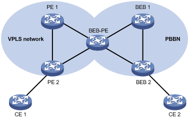
To configure the switch to support VPLS and MAC-in-MAC dual-stack, you need to create a VSI that supports VPLS and MAC-in-MAC dual-stack. To create such a VSI, specify the peer discovery mechanism, enable the MAC-in-MAC function, and specify the Backbone Service Instance Identifier (I-SID) for MAC-in-MAC when creating the VSI.
To configure the switch to support VPLS and MAC-in-MAC dual-stack:
|
Step |
Command |
|
1. Enter system view. |
system-view |
|
2. Create a VSI that supports both VPLS and MAC-in-MAC, and enter VSI view. |
vsi vsi-name { { auto | static } minm i-sid i-sid | minm i-sid i-sid { auto | static } } |
|
|
NOTE: A VSI enabled with the hub-spoke capability (the hub-spoke keyword included in the vsi static command) does not support cooperation with the MAC-in-MAC feature. |
Configuring MAC address learning
To configure the MAC address learning function:
|
Step |
Command |
Remarks |
|
1. Enter system view. |
system-view |
N/A |
|
2. Enter VSI view. |
vsi vsi-name |
N/A |
|
3. Enable/disable MAC address learning for the VPLS instance. |
mac-learning { enable | disable } |
Optional. Enabled by default. |
|
4. Specify a MAC address learning mode for the VPLS instance. |
mac-learn-style { qualify | unqualify } |
Optional. unqualify by default. |
|
5. Set the maximum number of MAC addresses that the switch can learn for the VPLS instance. |
mac-table limit mac-limit-number |
Optional. 65536 by default.. |
|
6. Enable the MAC address move function, so when the incoming interfaces of packets change, the device changes the interfaces in the corresponding MAC address entries accordingly. |
mac-move enable |
Optional. Disabled by default. |
Configuring VPLS instance attributes
To configure VPLS instance attributes:
|
Step |
Command |
Remarks |
|
1. Enter system view. |
system-view |
N/A |
|
2. Enter VSI view. |
vsi vsi-name |
N/A |
|
3. Specify the encapsulation type of the VPLS instance. |
encapsulation { bgp-vpls | ethernet | vlan } |
Optional. vlan by default, which corresponds to the VSI PW encapsulation type of tagged. |
|
4. Set the MTU of the VPLS instance. |
mtu mtu |
Optional. 1,500 bytes by default. If a base card is inserted into the switch, set the MTU to 8192 bytes; otherwise, forwarded packets may get lost. For information about base card and subcard models, see the appendix in the switch installation guide |
|
5. Set the description of the VPLS instance. |
description text |
Optional. No description set by default |
|
6. Shut down the VPLS service of the VPLS instance. |
shutdown |
Optional. By default, the VPLS service of a VPLS instance is enabled. |
|
7. Specify a tunneling policy for the VPLS instance. |
tnl-policy tunnel-policy-name |
Optional. By default, no tunneling policy is specified for a VPLS instance and a VPLS instance uses the default tunneling policy. The default tunneling policy selects only one tunnel (on load balancing) in this order: LSP tunnel, CR-LSP tunnel. For how to configure a tunneling policy, see the chapter “Configuring MPLS L3VPN.” |
Configuring traffic policing for an AC
Traffic policing controls packet transmission to avoid network congestion.
Use one of the following methods to perform traffic policing for an AC:
· If you want to bind the VPLS instance to a Layer 3 interface, you can configure QoS on the Layer 3 interface for traffic policing of the AC.
· If you want to bind the VPLS instance to a service instance, you need to apply global CAR actions for the service instance for traffic policing of the AC.
After you apply an inbound or outbound global CAR action for a service instance, the device polices the inbound or outbound traffic matching the service instance according to the applied global CAR action.
This configuration task describes how to apply a CAR action for a service instance.
Configuration prerequisites
Use the qos car command in system view to configure a global CAR action. For more information about CAR, see ACL and QoS Configuration Guide.
Configuration procedure
To apply a global CAR action for a service instance:
|
Step |
Command |
Remarks |
|
1. Enter system view. |
system-view |
N/A |
|
2. Enter the view of the Layer 2 Ethernet interface connected to the CE. |
interface interface-type interface-number |
N/A |
|
3. Enter service instance view. |
service-instance instance-id |
N/A |
|
4. Apply a global CAR action to the inbound or outbound traffic on the AC. |
car { inbound | outbound } name car-name |
By default, no global CAR is applied to an AC. |
|
|
NOTE: To configure traffic policing for an AC, you must first configure this task before you bind the service instance to the VPLS instance. |
Inspecting PWs
On a VPLS network, you can use the MPLS LSP ping function to check PW connectivity and get necessary information for troubleshooting PW failures.
On the local PE, the MPLS LSP ping function adds the label of the PW to be tested into MPLS Echo Request messages so that the messages travel along the PW. The local PE determines whether the PW is valid and reachable according to the replies received from the peer PE.
To check the connectivity of a PW:
|
Task |
Command |
Remarks |
|
Use MPLS LSP ping to check the connectivity of a PW. |
ping lsp [ -a source-ip | -c count | -exp exp-value | -h ttl-value | -m wait-time | -r reply-mode | -s packet-size | -t time-out | -v ] * pw ip-address pw-id pw-id |
Available in any view |
|
|
NOTE: · MPLS LSP ping can be used to inspect only an LDP PW. · To use an S9500E switch to check the reachability of the VC to a peer PE, make sure that the peer PE supports VC inspection. The peer PE, however, cannot use this function to check the reachability of the VC to the S9500E switch. |
Displaying and maintaining VPLS
|
Task |
Command |
Remarks |
|
Display the VPLS information in the BGP routing table. |
display bgp vpls { all | group [ group-name ] | peer [ [ ip-address ] verbose ] | route-distinguisher route-distinguisher [ site-id site-id [ label-offset label-offset ] ] } [ | { begin | exclude | include } regular-expression ] |
Available in any view |
|
Display the MAC address table information of one or all VPLS instances. |
display mac-address vsi [ vsi-name ] [ blackhole | dynamic | static ] [ count ] [ | { begin | exclude | include } regular-expression ] |
Available in any view |
|
Display information about VPLS connections. |
display vpls connection [ bgp | ldp | vsi vsi-name ] [ block | down | up ] [ verbose ] [ | { begin | exclude | include } regular-expression ] |
Available in any view |
|
Display information about VPLS AC entries on a switch running in standalone mode. |
display mpls l2vpn fib ac vpls [ vsi vsi-name | interface interface-type interface-number [ service-instance service-instanceid ] ] [ slot slot-number ] [ verbose ] [ | { begin | exclude | include } regular-expression ] |
Available in any view |
|
Display information about VPLS AC entries on a switch running in IRF mode. |
display mpls l2vpn fib ac vpls [ vsi vsi-name | interface interface-type interface-number [ service-instance service-instanceid ] ] [ chassis chassis-number slot slot-number ] [ verbose ] [ | { begin | exclude | include } regular-expression ] |
Available in any view |
|
Display information about VPLS PW entries on a switch running in standalone mode. |
display mpls l2vpn fib pw vpls [ vsi vsi-name [ link link-id ] ] [ slot slot-number ] [ verbose ] [ | { begin | exclude | include } regular-expression ] |
Available in any view |
|
Display information about VPLS PW entries on a switch running in IRF mode. |
display mpls l2vpn fib pw vpls [ vsi vsi-name [ link link-id ] ] [ chassis chassis-number slot slot-number ] [ verbose ] [ | { begin | exclude | include } regular-expression ] |
Available in any view |
|
Display information about one or all VPLS instances. |
display vsi [ vsi-name ] [ verbose ] [ | { begin | exclude | include } regular-expression ] |
Available in any view |
|
Display information about remote VPLS connections. |
display vsi remote { bgp | ldp } [ | { begin | exclude | include } regular-expression ] |
Available in any view |
|
Display information about service instances on an interface. |
display service-instance interface interface-type interface-number [ service-instance service-instance-id ] [ | { begin | exclude | include } regular-expression ] |
Available in any view |
|
Display information about one or all PW class templates. |
display pw-class [ pw-class-name ] [ | { begin | exclude | include } regular-expression ] |
Available in any view |
|
Display information about one or all fast switching groups. |
display l2vpn fast-switch-group [ group-index ] [ | { begin | exclude | include } regular-expression ] |
Available in any view |
|
Clear the MAC address table of one or all VPLS instances. |
reset mac-address vsi [ vsi-name ] |
Available in user view |
|
Clear the traffic statistics for a service instance on an interface. |
reset service-instance statistics [ interface interface-type interface-number [ service-instance instance-id [ inbound | outbound ] ] ] |
Available in user view |
VPLS configuration examples
|
|
NOTE: By default, Ethernet interfaces, VLAN interfaces, and aggregate interfaces are in DOWN state. To configure such an interface, first use the undo shutdown command to bring the interface up. |
Configuring VPLS instances
Network requirements
CE 1 and CE 2 reside in different sites but both belong to VPN 1. The PEs are connected to each other through interface VLAN-interface 10.
On each PE, configure an LDP VPLS instance aaa (the Martini mode) and a BGP VPLS instance bbb (the Kompella mode). The AS number is 100.
On each PE, configure service instances and bind the VPLS instances to forward specific packets.
· Service instance 1000 matches the received packets that carry VLAN tag 100 on GigabitEthernet 3/0/1. The matched packets are forwarded by VPLS instance aaa.
· Service instance 2000 matches the received packets that carry VLAN tag 200 on GigabitEthernet 3/0/1. The matched packets are forwarded by VPLS instance bbb.
Configuration procedure
1. Configure PE 1.
# Configure the IGP protocol, which is OSPF in this example. (Details not shown)
# Configure basic MPLS.
<Sysname> system-view
[Sysname] sysname PE1
[PE1] interface loopback 0
[PE1-LoopBack0] ip address 1.1.1.9 32
[PE1-LoopBack0] quit
[PE1] mpls lsr-id 1.1.1.9
[PE1] mpls
[PE1-mpls] quit
[PE1] mpls ldp
[PE1-mpls-ldp] quit
# Configure interface VLAN-interface 10.
[PE1] interface vlan-interface 10
[PE1-Vlan-interface10] ip address 10.10.10.10 24
# Configure basic MPLS on the VLAN interface.
[PE1-Vlan-interface10] mpls
[PE1-Vlan-interface10] mpls ldp
[PE1-Vlan-interface10] quit
# Configure the remote LDP session.
[PE1] mpls ldp remote-peer 1
[PE1-mpls-remote-1] remote-ip 2.2.2.9
[PE1-mpls-remote-1] quit
# Configure BGP extension.
[PE1] bgp 100
[PE1-bgp] peer 2.2.2.9 as-number 100
[PE1-bgp] peer 2.2.2.9 connection-interface loopback 0
[PE1-bgp] vpls-family
[PE1-bgp-af-vpls] peer 2.2.2.9 enable
[PE1-bgp-af-vpls] quit
[PE1-bgp] quit
# Enable L2VPN and MPLS L2VPN.
[PE1] l2vpn
[PE1-l2vpn] mpls l2vpn
[PE1-l2vpn] quit
# Configure the basic attributes of VPLS instance aaa, which uses LDP.
[PE1] vsi aaa static
[PE1-vsi-aaa] pwsignal ldp
[PE1-vsi-aaa-ldp] vsi-id 500
[PE1-vsi-aaa-ldp] peer 2.2.2.9
[PE1-vsi-aaa-ldp] quit
[PE1-vsi-aaa] quit
# Configure the basic attributes of VPLS instance bbb, which uses BGP.
[PE1] vsi bbb auto
[PE1-vsi-bbb] pwsignal bgp
[PE1-vsi-bbb-bgp] route-distinguisher 100:1
[PE1-vsi-bbb-bgp] vpn-target 111:1
[PE1-vsi-bbb-bgp] site 1 range 10
[PE1-vsi-bbb-bgp] quit
[PE1-vsi-bbb] quit
# On interface GigabitEthernet 3/0/1 connected to CE 1, create service instances and bind the VPLS instances.
[PE1] interface GigabitEthernet 3/0/1
[PE1-GigabitEthernet3/0/1] service-instance 1000
[PE1-GigabitEthernet3/0/1-srv1000] encapsulation s-vid 100
[PE1-GigabitEthernet3/0/1-srv1000] xconnect vsi aaa
[PE1-GigabitEthernet3/0/1-srv1000] quit
[PE1-GigabitEthernet3/0/1] service-instance 2000
[PE1-GigabitEthernet3/0/1-srv1000] encapsulation s-vid 200
[PE1-GigabitEthernet3/0/1-srv1000] xconnect vsi bbb
[PE1-GigabitEthernet3/0/1-srv1000] quit
2. Configure PE 2.
# Configure the IGP protocol, which is OSPF in this example. (Details not shown)
# Configure basic MPLS.
<Sysname> system-view
[Sysname] sysname PE2
[PE2] interface loopback 0
[PE2-LoopBack0] ip address 2.2.2.9 32
[PE2-LoopBack0] quit
[PE2] mpls lsr-id 2.2.2.9
[PE2] mpls
[PE1-mpls] quit
[PE2] mpls ldp
[PE2-mpls-ldp] quit
# Configure interface VLAN-interface 10.
[PE2] interface vlan-interface 10
[PE2-Vlan-interface10] ip address 10.10.10.11 24
# Configure basic MPLS on the VLAN interface.
[PE2-Vlan-interface10] mpls
[PE2-Vlan-interface10] mpls ldp
[PE2-Vlan-interface10] quit
# Configure the remote LDP session.
[PE2] mpls ldp remote-peer 2
[PE2-mpls-remote-2] remote-ip 1.1.1.9
[PE2-mpls-remote-2] quit
# Configure BGP extensions.
[PE2] bgp 100
[PE2-bgp] peer 1.1.1.9 as-number 100
[PE2-bgp] peer 1.1.1.9 connection-interface loopback 0
[PE2-bgp] vpls-family
[PE2-bgp-af-vpls] peer 1.1.1.9 enable
[PE2-bgp-af-vpls] quit
[PE2-bgp] quit
# Enable L2VPN and MPLS L2VPN.
[PE2] l2vpn
[PE2-l2vpn] mpls l2vpn
[PE2-l2vpn] quit
# Configure the basic attributes of VPLS instance aaa, which uses LDP.
[PE2] vsi aaa static
[PE2-vsi-aaa] pwsignal ldp
[PE2-vsi-aaa-ldp] vsi-id 500
[PE2-vsi-aaa-ldp] peer 1.1.1.9
[PE2-vsi-aaa-ldp] quit
[PE2-vsi-aaa] quit
# Configure the basic attributes of VPLS instance bbb, which uses BGP.
[PE2] vsi bbb auto
[PE2-vsi-bbb] pwsignal bgp
[PE2-vsi-bbb-bgp] route-distinguisher 100:1
[PE2-vsi-bbb-bgp] vpn-target 111:1
[PE2-vsi-bbb-bgp] site 2 range 10
[PE2-vsi-bbb-bgp] quit
[PE2-vsi-bbb] quit
# On interface GigabitEthernet 3/0/1 connected to CE 2, create service instances and bind the VPLS instances.
[PE2] interface GigabitEthernet 3/0/1
[PE2-GigabitEthernet3/0/1] service-instance 1000
[PE2-GigabitEthernet3/0/1-srv1000] encapsulation s-vid 100
[PE2-GigabitEthernet3/0/1-srv1000] xconnect vsi aaa
[PE2-GigabitEthernet3/0/1-srv1000] quit
[PE2-GigabitEthernet3/0/1] service-instance 2000
[PE2-GigabitEthernet3/0/1-srv1000] encapsulation s-vid 200
[PE2-GigabitEthernet3/0/1-srv1000] xconnect vsi bbb
[PE2-GigabitEthernet3/0/1-srv1000] quit
3. Verify the configuration.
After you complete the configuration, issue the display vpls connection command on the PEs. You will see that PW connections in up state have been established.
Configuring H-VPLS with LSP access
Network requirements
UPE and NPE 1 are connected through interfaces named VLAN-interface 10. NPE 1 and NPE 3 are connected to each other through interfaces named VLAN-interface 20.
Create a U-PW connection between UPE and NPE 1 and an N-PW connection between NPE 1 and NPE 3. Create a VPLS instance aaa using LDP, the Martini mode.
On UPE and NPE 3, configure a service instance and bind it to the VPLS instance aaa. The service instance matches the received packets that carry VLAN tag 100 on GigabitEthernet 3/0/1. The matched packets are forwarded by VPLS instance aaa.
Configuration procedure
1. Configure the IGP protocol on the MPLS backbone, which is OSPF in this example. (Details not shown)
2. Configure UPE.
# Configure basic MPLS.
<Sysname> system-view
[Sysname] sysname UPE
[UPE] interface loopback 0
[UPE-LoopBack0] ip address 1.1.1.9 32
[UPE-LoopBack0] quit
[UPE] mpls lsr-id 1.1.1.9
[UPE] mpls
[UPE-mpls] quit
[UPE] mpls ldp
[UPE-mpls-ldp] quit
# Configure basic MPLS on the interface connected to NPE 1.
[UPE] interface vlan-interface 10
[UPE-Vlan-interface10] ip address 10.1.1.1 24
[UPE-Vlan-interface10] mpls
[UPE-Vlan-interface10] mpls ldp
[UPE-Vlan-interface10] quit
# Configure the remote LDP session.
[UPE] mpls ldp remote-peer 1
[UPE-mpls-remote-1] remote-ip 2.2.2.9
[UPE-mpls-remote-1] quit
# Enable L2VPN and MPLS L2VPN.
[UPE] l2vpn
[UPE-l2vpn] mpls l2vpn
[UPE-l2vpn] quit
# Configure the basic attributes of VPLS instance aaa, which uses LDP.
[UPE] vsi aaa static
[UPE-vsi-aaa] pwsignal ldp
[UPE-vsi-aaa-ldp] vsi-id 500
[UPE-vsi-aaa-ldp] peer 2.2.2.9
[UPE-vsi-aaa-ldp] quit
[UPE-vsi-aaa] quit
# On interface GigabitEthernet 3/0/1 connected to CE 1, create a service instance and bind VPLS instance aaa to the service instance.
[UPE] interface GigabitEthernet 3/0/1
[UPE-GigabitEthernet3/0/1] service-instance 1000
[UPE-GigabitEthernet3/0/1-srv1000] encapsulation s-vid 100
[UPE-GigabitEthernet3/0/1-srv1000] xconnect vsi aaa
[UPE-GigabitEthernet3/0/1-srv1000] quit
[UPE-GigabitEthernet3/0/1] quit
3. Configure NPE 1.
# Configure basic MPLS.
<Sysname> system-view
[Sysname] sysname NPE1
[NPE1] interface loopback 0
[NPE1-LoopBack0] ip address 2.2.2.9 32
[NPE1-LoopBack0] quit
[NPE1] mpls lsr-id 2.2.2.9
[NPE1] mpls
[NPE1–mpls] quit
[NPE1] mpls ldp
[NPE1–mpls-ldp] quit
# Configure basic MPLS on the interface connected to UPE.
[NPE1] interface vlan-interface 10
[NPE1-Vlan-interface10] ip address 10.1.1.2 24
[NPE1-Vlan-interface10] mpls
[NPE1-Vlan-interface10] mpls ldp
[NPE1-Vlan-interface10] quit
# Configure basic MPLS on the interface connected to NPE 3.
[NPE1] interface vlan-interface 20
[NPE1-Vlan-interface20] ip address 11.1.1.1 24
[NPE1-Vlan-interface20] mpls
[NPE1-Vlan-interface20] mpls ldp
[NPE1-Vlan-interface20] quit
# Configure the remote LDP peer UPE.
[NPE1] mpls ldp remote-peer 2
[NPE1-mpls-remote-2] remote-ip 1.1.1.9
[NPE1-mpls-remote-2] quit
# Configure the remote LDP peer NPE 3.
[NPE1] mpls ldp remote-peer 3
[NPE1-mpls-remote-3] remote-ip 3.3.3.9
[NPE1-mpls-remote-3] quit
# Enable L2VPN and MPLS L2VPN.
[NPE1] l2vpn
[NPE1-l2vpn] mpls l2vpn
[NPE1-l2vpn] quit
# Configure the basic attributes of VPLS instance aaa, which uses LDP.
[NPE1] vsi aaa static
[NPE1-vsi-aaa] pwsignal ldp
[NPE1-vsi-aaa-ldp] vsi-id 500
[NPE1-vsi-aaa-ldp] peer 1.1.1.9 upe
[NPE1-vsi-aaa-ldp] peer 3.3.3.9
[NPE1-vsi-aaa-ldp] quit
[NPE1-vsi-aaa] quit
4. Configure NPE 3.
# Configure basic MPLS.
<Sysname> system-view
[Sysname] sysname NPE3
[NPE3] interface loopback 0
[NPE3-LoopBack0] ip address 3.3.3.9 32
[NPE3-LoopBack0] quit
[NPE3] mpls lsr-id 3.3.3.9
[NPE3] mpls
[NPE3–mpls] quit
[NPE3] mpls ldp
[NPE3–mpls-ldp] quit
# Configure basic MPLS on the interface connected to NPE 1.
[NPE3] interface vlan-interface 20
[NPE3-Vlan-interface20] ip address 11.1.1.2 24
[NPE3-Vlan-interface20] mpls
[NPE3-Vlan-interface20] mpls ldp
[NPE3-Vlan-interface20] quit
# Configure the remote LDP session.
[NPE3] mpls ldp remote-peer 1
[NPE3-mpls-remote-1] remote-ip 2.2.2.9
[NPE3-mpls-remote-1] quit
# Enable L2VPN and MPLS L2VPN.
[NPE3] l2vpn
[NPE3-l2vpn] mpls l2vpn
[NPE3-l2vpn] quit
# Configure the basic attributes of VPLS instance aaa, which uses LDP.
[NPE3] vsi aaa static
[NPE3-vsi-aaa] pwsignal ldp
[NPE3-vsi-aaa-ldp] vsi-id 500
[NPE3-vsi-aaa-ldp] peer 2.2.2.9
[NPE3-vsi-aaa-ldp] quit
[NPE3-vsi-aaa] quit
# On interface GigabitEthernet 3/0/1 connected to CE 2, create a service instance and bind VPLS instance aaa to the service instance.
[NPE3] interface GigabitEthernet 3/0/1
[NPE3-GigabitEthernet3/0/1] service-instance 1000
[NPE3-GigabitEthernet3/0/1-srv1000] encapsulation s-vid 100
[NPE3-GigabitEthernet3/0/1-srv1000] xconnect vsi aaa
[NPE3-GigabitEthernet3/0/1-srv1000] quit
[NPE3-GigabitEthernet3/0/1] quit
5. Verify the configuration.
After you complete previous configurations, issue the display vpls connection command on the PEs. You will see that a PW connection in up state has been established.
Configuring hub-spoke VPLS
Network requirements
Set up a PW between Spoke-PE 1 and Hub-PE and a PW between Spoke-PE 2 and Hub-PE.
Configure VPLS instance aaa to support hub-spoke networking.
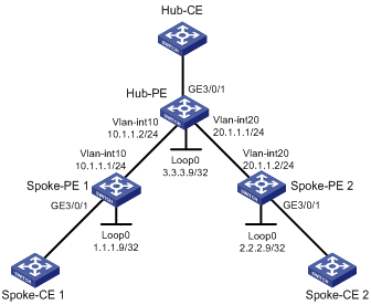
On Spoke-PE 1, Hub-PE, and Spoke-PE 2, configure a service instance and bind it to the VPLS instance aaa. The service instance matches the received packets that carry VLAN tag 100 on GigabitEthernet 3/0/1. The matched packets are forwarded by VPLS instance aaa.
Figure 11 Network diagram
Configuration procedure
1. Configure the IGP protocol on the MPLS backbone, which is OSPF in this example. (Details not shown)
2. Configure Spoke-PE 1.
# Configure basic MPLS.
<Sysname> system-view
[Sysname] sysname Spoke-PE1
[Spoke-PE1] interface loopback 0
[Spoke-PE1-LoopBack0] ip address 1.1.1.9 32
[Spoke-PE1-LoopBack0] quit
[Spoke-PE1] mpls lsr-id 1.1.1.9
[Spoke-PE1] mpls
[Spoke-PE1–mpls] quit
[Spoke-PE1] mpls ldp
[Spoke-PE1-mpls-ldp] quit
# Configure basic MPLS on the interface connected to Hub-PE.
[Spoke-PE1] interface vlan-interface 10
[Spoke-PE1-Vlan-interface10] ip address 10.1.1.1 24
[Spoke-PE1-Vlan-interface10] mpls
[Spoke-PE1-Vlan-interface10] mpls ldp
[Spoke-PE1-Vlan-interface10] quit
# Configure the remote LDP peer Hub-PE.
[Spoke-PE1] mpls ldp remote-peer 1
[Spoke-PE1-mpls-remote-1] remote-ip 3.3.3.9
[Spoke-PE1-mpls-remote-1] quit
# Enable L2VPN and MPLS L2VPN.
[Spoke-PE1] l2vpn
[Spoke-PE1-l2vpn] mpls l2vpn
[Spoke-PE1-l2vpn] quit
# Configure the basic attributes of VPLS instance aaa, which uses LDP, and configure the peer as the hub.
[Spoke-PE1] vsi aaa static hub-spoke
[Spoke-PE1-vsi-aaa] pwsignal ldp
[Spoke-PE1-vsi-aaa-ldp] vsi-id 500
[Spoke-PE1-vsi-aaa-ldp] peer 3.3.3.9 hub
[Spoke-PE1-vsi-aaa-ldp] quit
[Spoke-PE1-vsi-aaa] quit
# On the interface GigabitEthernet 3/0/1 connected to Spoke-CE 1, create a service instance and bind the service instance with VPLS instance aaa.
[Spoke-PE1] interface GigabitEthernet 3/0/1
[Spoke-PE1-GigabitEthernet3/0/1] service-instance 1000
[Spoke-PE1-GigabitEthernet3/0/1-srv1000] encapsulation s-vid 100
[Spoke-PE1-GigabitEthernet3/0/1-srv1000] xconnect vsi aaa spoke
[Spoke-PE1-GigabitEthernet3/0/1-srv1000] quit
[Spoke-PE1-GigabitEthernet3/0/1] quit
3. Configure Spoke-PE 2.
# Configure basic MPLS.
<Sysname> system-view
[Sysname] sysname Spoke-PE2
[Spoke-PE2] interface loopback 0
[Spoke-PE2-LoopBack0] ip address 2.2.2.9 32
[Spoke-PE2-LoopBack0] quit
[Spoke-PE2] mpls lsr-id 2.2.2.9
[Spoke-PE2] mpls
[Spoke-PE2–mpls] quit
[Spoke-PE2] mpls ldp
[Spoke-PE2–mpls-ldp] quit
# Configure basic MPLS on the interface connected to Hub-PE.
[Spoke-PE2] interface vlan-interface 20
[Spoke-PE2-Vlan-interface20] ip address 20.1.1.1 24
[Spoke-PE2-Vlan-interface20] mpls
[Spoke-PE2-Vlan-interface20] mpls ldp
[Spoke-PE2-Vlan-interface20] quit
# Configure the remote LDP peer Hub-PE.
[Spoke-PE2] mpls ldp remote-peer 2
[Spoke-PE2-mpls-remote-2] remote-ip 3.3.3.9
[Spoke-PE2-mpls-remote-2] quit
# Enable L2VPN and MPLS L2VPN.
[Spoke-PE2] l2vpn
[Spoke-PE2-l2vpn] mpls l2vpn
[Spoke-PE2-l2vpn] quit
# Configure the basic attributes of VPLS instance aaa, which uses LDP, and configure the peer as the hub.
[Spoke-PE2] vsi aaa static hub-spoke
[Spoke-PE2-vsi-aaa] pwsignal ldp
[Spoke-PE2-vsi-aaa-ldp] vsi-id 500
[Spoke-PE2-vsi-aaa-ldp] peer 3.3.3.9 hub
[Spoke-PE2-vsi-aaa-ldp] quit
[Spoke-PE2-vsi-aaa] quit
# On the interface GigabitEthernet 3/0/1 connected to Spoke-CE 2, create a service instance and bind VPLS instance aaa to the service instance.
[Spoke-PE2] interface GigabitEthernet 3/0/1
[Spoke-PE2-GigabitEthernet3/0/1] service-instance 1000
[Spoke-PE2-GigabitEthernet3/0/1-srv1000] encapsulation s-vid 100
[Spoke-PE2-GigabitEthernet3/0/1-srv1000] xconnect vsi aaa spoke
[Spoke-PE2-GigabitEthernet3/0/1-srv1000] quit
[Spoke-PE2-GigabitEthernet3/0/1] quit
4. Configure Hub-PE.
# Configure basic MPLS.
<Sysname> system-view
[Sysname] sysname Hub-PE
[Hub-PE] interface loopback 0
[Hub-PE-LoopBack0] ip address 3.3.3.9 32
[Hub-PE-LoopBack0] quit
[Hub-PE] mpls lsr-id 3.3.3.9
[Hub-PE] mpls
[Hub-PE–mpls] quit
[Hub-PE] mpls ldp
[Hub-PE–mpls-ldp] quit
# Configure basic MPLS on the interface connected to Spoke-PE 1.
[Hub-PE] interface vlan-interface 10
[Hub-PE-Vlan-interface10] ip address 10.1.1.2 24
[Hub-PE-Vlan-interface10] mpls
[Hub-PE-Vlan-interface10] mpls ldp
[Hub-PE-Vlan-interface10] quit
# Configure basic MPLS on the interface connected to Spoke-PE 2.
[Hub-PE] interface vlan-interface 20
[Hub-PE-Vlan-interface20] ip address 20.1.1.2 24
[Hub-PE-Vlan-interface20] mpls
[Hub-PE-Vlan-interface20] mpls ldp
[Hub-PE-Vlan-interface20] quit
# Configure the remote LDP sessions.
[Hub-PE] mpls ldp remote-peer 1
[Hub-PE-mpls-remote-1] remote-ip 1.1.1.9
[Hub-PE-mpls-remote-1] quit
[Hub-PE] mpls ldp remote-peer 2
[Hub-PE-mpls-remote-2] remote-ip 2.2.2.9
[Hub-PE-mpls-remote-2] quit
# Enable L2VPN and MPLS L2VPN.
[Hub-PE] l2vpn
[Hub-PE-l2vpn] mpls l2vpn
[Hub-PE-l2vpn] quit
# Configure the basic attributes of VPLS instance aaa, which uses LDP, and configure the peers as spokes.
[Hub-PE] vsi aaa static hub-spoke
[Hub-PE-vsi-aaa] pwsignal ldp
[Hub-PE-vsi-aaa-ldp] vsi-id 500
[Hub-PE-vsi-aaa-ldp] peer 1.1.1.9 spoke
[Hub-PE-vsi-aaa-ldp] peer 2.2.2.9 spoke
[Hub-PE-vsi-aaa-ldp] quit
[Hub-PE-vsi-aaa] quit
# On the interface GigabitEthernet 3/0/1 connected to Hub-CE, create a service instance and bind VPLS instance aaa to the service instance.
[Hub-PE] interface GigabitEthernet 3/0/1
[Hub-PE-GigabitEthernet3/0/1] service-instance 1000
[Hub-PE-GigabitEthernet3/0/1-srv1000] encapsulation s-vid 100
[Hub-PE-GigabitEthernet3/0/1-srv1000] xconnect vsi aaa hub
[Hub-PE-GigabitEthernet3/0/1-srv1000] quit
[Hub-PE-GigabitEthernet3/0/1] quit
5. Verify the configuration.
After you complete previous configurations, issue the display vpls connection command on the PEs. You will see that a PW connection in up state has been established.
Configuring PW redundancy for H-VPLS access
Network requirements
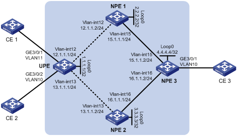
As shown in Figure 12, establish a U-PW between UPE and NPE 1 and a backup U-PW between UPE and NPE 2. Establish an N-PW between NPE 1 and NPE 3 and another N-PW between NPE 2 and NPE 3.
Configure a VPLS instance that supports H-VPLS network. On UPE and NPE 3, configure a service instance and bind it to the VPLS instance. The service instance matches the received packets that carry VLAN tag 100 on GigabitEthernet 3/0/1. The matched packets are forwarded by the VPLS instance.
Configuration procedure
1. Configure the IGP protocol on the MPLS backbone, which is OSPF in this example. (Details not shown)
2. Configure UPE.
# Configure basic MPLS.
<Sysname> system-view
[Sysname] sysname UPE
[UPE] interface loopback 0
[UPE-LoopBack0] ip address 1.1.1.1 32
[UPE-LoopBack0] quit
[UPE] mpls lsr-id 1.1.1.1
[UPE] mpls
[UPE-mpls] quit
[UPE] mpls ldp
[UPE-mpls-ldp] quit
# Configure an IP address for the interface connected to NPE 1, and enable MPLS and MPLS LDP.
[UPE] interface vlan-interface 12
[UPE-Vlan-interface12] ip address 12.1.1.1 24
[UPE-Vlan-interface12] mpls
[UPE-Vlan-interface12] mpls ldp
[UPE-Vlan-interface12] quit
# Configure an IP address for the interface connected to NPE 2, and enable MPLS and MPLS LDP.
[UPE] interface vlan-interface 13
[UPE-Vlan-interface13] ip address 13.1.1.1 255.255.255.0
[UPE-Vlan-interface13] mpls
[UPE-Vlan-interface13] mpls ldp
[UPE-Vlan-interface13] quit
# Configure the remote LDP peer NPE 1.
[UPE] mpls ldp remote-peer 1
[UPE-mpls-remote-1] remote-ip 2.2.2.2
[UPE-mpls-remote-1] quit
# Configure the remote LDP peer NPE 2.
[UPE] mpls ldp remote-peer 2
[UPE-mpls-remote-1] remote-ip 3.3.3.3
[UPE-mpls-remote-1] quit
# Enable L2VPN and MPLS L2VPN.
[UPE] l2vpn
[UPE-l2vpn] mpls l2vpn
[UPE-l2vpn] quit
# Configure the basic attributes of VPLS instance aaa, which uses LDP.
[UPE] vsi aaa static
[UPE-vsi-aaa] pwsignal ldp
[UPE-vsi-aaa-ldp] vsi-id 500
[UPE-vsi-aaa-ldp] peer 2.2.2.2 backup-peer 3.3.3.3
[UPE-vsi-aaa-ldp] dual-npe revertive wtr-time 1
[UPE-vsi-aaa-ldp] quit
[UPE-vsi-aaa] quit
# On the interface connected to CE 1, create a service instance and bind the VSI.
[UPE] interface GigabitEthernet 3/0/1
[UPE-GigabitEthernet3/0/1] service-instance 1000
[UPE-GigabitEthernet3/0/1-srv1000] encapsulation s-vid 10
[UPE-GigabitEthernet3/0/1-srv1000] xconnect vsi aaa
[UPE-GigabitEthernet3/0/1-srv1000] quit
# On the interface connected to CE 2, create a service instance and bind the VSI.
[UPE] interface GigabitEthernet 3/0/2
[UPE-GigabitEthernet3/0/2] service-instance 1000
[UPE-GigabitEthernet3/0/2-srv1000] encapsulation s-vid 11
[UPE-GigabitEthernet3/0/2-srv1000] xconnect vsi aaa
[UPE-GigabitEthernet3/0/2-srv1000] quit
3. Configure NPE 1.
# Configure basic MPLS.
<Sysname> system-view
[Sysname] sysname NPE1
[NPE1] interface loopback 0
[NPE1-LoopBack0] ip address 2.2.2.2 32
[NPE1-LoopBack0] quit
[NPE1] mpls lsr-id 2.2.2.2
[NPE1] mpls
[NPE1–mpls] quit
[NPE1] mpls ldp
[NPE1–mpls-ldp] quit
# Configure an IP address for the interface connected to UPE, and enable MPLS and MPLS LDP.
[NPE1] interface vlan-interface 12
[NPE1-Vlan-interface12] ip address 12.1.1.2 24
[NPE1-Vlan-interface12] mpls
[NPE1-Vlan-interface12] mpls ldp
[NPE1-Vlan-interface12] quit
# Configure an IP address for the interface connected to NPE 3, and enable MPLS and MPLS LDP.
[NPE1] interface vlan-interface 15
[NPE1-Vlan-interface15] ip address 15.1.1.1 24
[NPE1-Vlan-interface15] mpls
[NPE1-Vlan-interface15] mpls ldp
[NPE1-Vlan-interface15] quit
# Configure the remote LDP peer UPE.
[NPE1] mpls ldp remote-peer 2
[NPE1-mpls-remote-2] remote-ip 1.1.1.1
[NPE1-mpls-remote-2] quit
# Configure the remote LDP peer NPE 3.
[NPE1] mpls ldp remote-peer 3
[NPE1-mpls-remote-3] remote-ip 4.4.4.4
[NPE1-mpls-remote-3] quit
# Enable L2VPN and MPLS L2VPN.
[NPE1] l2vpn
[NPE1-l2vpn] mpls l2vpn
[NPE1-l2vpn] quit
# Configure the basic attributes of VPLS instance aaa, which uses LDP.
[NPE1] vsi aaa static
[NPE1-vsi-aaa] pwsignal ldp
[NPE1-vsi-aaa-ldp] vsi-id 500
[NPE1-vsi-aaa-ldp] peer 1.1.1.1 upe
[NPE1-vsi-aaa-ldp] peer 4.4.4.4
[NPE1-vsi-aaa-ldp] quit
[NPE1-vsi-aaa] quit
The configuration procedure on NPE 2 is similar to that on NPE 1. (Details not shown)
4. Configure NPE 3.
# Configure basic MPLS.
<Sysname> system-view
[Sysname] sysname NPE3
[NPE3] interface loopback 0
[NPE3-LoopBack0] ip address 4.4.4.4 32
[NPE3-LoopBack0] quit
[NPE3] mpls lsr-id 4.4.4.4
[NPE3] mpls
[NPE3–mpls] quit
[NPE3] mpls ldp
[NPE3–mpls-ldp] quit
# Configure an IP address for the interface connected to NPE 1, and enable MPLS and MPLS LDP.
[NPE3] interface vlan-interface 15
[NPE3-Vlan-interface15] ip address 15.1.1.2 24
[NPE3-Vlan-interface15] mpls
[NPE3-Vlan-interface15] mpls ldp
[NPE3-Vlan-interface15] quit
# Configure an IP address for the interface connected to NPE 2, and enable MPLS and MPLS LDP.
[NPE3] interface vlan-interface 16
[NPE3-Vlan-interface16] ip address 16.1.1.2 255.255.255.0
[NPE3-Vlan-interface16] mpls
[NPE3-Vlan-interface16] mpls ldp
[NPE3-Vlan-interface16] quit
# Configure the remote LDP session.
[NPE3] mpls ldp remote-peer 1
[NPE3-mpls-remote-1] remote-ip 2.2.2.2
[NPE3-mpls-remote-1] quit
[NPE3] mpls ldp remote-peer 2
[NPE3-mpls-remote-2] remote-ip 3.3.3.3
[NPE3-mpls-remote-2] quit
# Enable L2VPN and MPLS L2VPN.
[NPE3] l2vpn
[NPE3-l2vpn] mpls l2vpn
[NPE3-l2vpn] quit
# Configure the basic attributes of VPLS instance aaa, which uses LDP.
[NPE3] vsi aaa static
[NPE3-vsi-aaa] pwsignal ldp
[NPE3-vsi-aaa-ldp] vsi-id 500
[NPE3-vsi-aaa-ldp] peer 2.2.2.2
[NPE3-vsi-aaa-ldp] peer 3.3.3.3
[NPE3-vsi-aaa-ldp] quit
[NPE3-vsi-aaa] quit
# Create service instance on GigabitEthernet 3/0/1, the interface connecting CE 3, and bind the VSI.
[NPE3] interface GigabitEthernet 3/0/1
[NPE3-GigabitEthernet3/0/1] service-instance 1000
[NPE3-GigabitEthernet3/0/1-srv1000] encapsulation s-vid 10
[NPE3-GigabitEthernet3/0/1-srv1000] xconnect vsi aaa
[NPE3-GigabitEthernet3/0/1-srv1000] quit
5. Verify the configuration.
After you complete previous configurations, execute the display vpls connection command on the PEs. You will see that a PW connection in up state has been established.
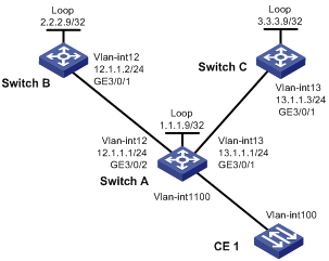
Configuring BFD for the main link in an H-VPLS network
Network requirements
In the H-VPLS network, Switch A is the UPE, Switch B is the main NPE and Switch C is the backup NPE. Enable MPLS on the interfaces connecting the switches, and enable OSPF on the switches to ensure IP connectivity.
Configure BFD for the link between Switch A and Switch B, so when the link is down, BFD can detect the link failure and inform the MPLS LDP protocol for fast PW switchover.
Figure 13 Network diagram
Configuration procedure
1. Configure basic MPLS.
# Configure Switch A.
<SwitchA> system-view
[SwitchA] mpls lsr-id 1.1.1.9
[SwitchA] mpls
[SwitchA-mpls] quit
[SwitchA] mpls ldp
[SwitchA-mpls-ldp] quit
[SwitchA] mpls ldp remote-peer switchb
[SwitchA-mpls-ldp-remote-switchb] remote-ip 2.2.2.9
[SwitchA-mpls-ldp-remote-switchb] remote-ip bfd
[SwitchA-mpls-ldp-remote-switchb] quit
[SwitchA] mpls ldp remote-peer switchc
[SwitchA-mpls-ldp-remote-switchc] remote-ip 3.3.3.9
[SwitchA-mpls-ldp-remote-switchc] remote-ip bfd
[SwitchA-mpls-ldp-remote-switchc] quit
[SwitchA] vlan 12
[SwitchA-vlan12] port gigabitethernet 3/0/2
[SwitchA-vlan12] quit
[SwitchA] vlan 13
[SwitchA-vlan13] port gigabitethernet 3/0/1
[SwitchA-vlan13] quit
[SwitchA] interface vlan-interface 12
[SwitchA-Vlan-interface12] mpls
[SwitchA-Vlan-interface12] mpls ldp
[SwitchA-Vlan-interface12] quit
[SwitchA] interface vlan-interface 13
[SwitchA-Vlan-interface13] mpls
[SwitchA-Vlan-interface13] mpls ldp
[SwitchA-Vlan-interface13] quit
# Configure Switch B.
<SwitchB> system-view
[SwitchB] mpls lsr-id 2.2.2.9
[SwitchB] mpls
[SwitchB-mpls] quit
[SwitchB] mpls ldp
[SwitchB-mpls-ldp] quit
[SwitchB] mpls ldp remote-peer switcha
[SwitchB-mpls-ldp-remote-switcha] remote-ip 1.1.1.9
[SwitchB-mpls-ldp-remote-switcha] remote-ip bfd
[SwitchB-mpls-ldp-remote-switcha] quit
[SwitchB] vlan 12
[SwitchB-vlan12] port gigabitethernet 3/0/1
[SwitchB-vlan12] quit
[SwitchB] interface vlan-interface 12
[SwitchB-Vlan-interface12] mpls
[SwitchB-Vlan-interface12] mpls ldp
[SwitchB-Vlan-interface12] quit
# Configure Switch C.
<SwitchC> system-view
[SwitchC] mpls lsr-id 3.3.3.9
[SwitchC] mpls
[SwitchC-mpls] quit
[SwitchC] mpls ldp
[SwitchC-mpls-ldp] quit
[SwitchC] mpls ldp remote-peer switcha
[SwitchC-mpls-ldp-remote-switcha] remote-ip 1.1.1.9
[SwitchC-mpls-ldp-remote-switcha] remote-ip bfd
[SwitchC-mpls-ldp-remote-switcha] quit
[SwitchC] vlan 13
[SwitchC-vlan13] port gigabitethernet 3/0/1
[SwitchC-vlan13] quit
[SwitchC] interface vlan-interface 13
[SwitchC-Vlan-interface13] mpls
[SwitchC-Vlan-interface13] mpls ldp
[SwitchC-Vlan-interface13] quit
2. Configure related interfaces on the switches.
# Configure Switch A.
[SwitchA] interface vlan-interface 12
[SwitchA-Vlan-interface12] ip address 12.1.1.1 24
[SwitchA-Vlan-interface12] quit
[SwitchA] interface vlan-interface 13
[SwitchA-Vlan-interface13] ip address 13.1.1.1 24
[SwitchA-Vlan-interface13] quit
[SwitchA] interface loopback 0
[SwitchA-LoopBack0] ip address 1.1.1.9 32
[SwitchA-LoopBack0] quit
# Configure Switch B.
[SwitchB] interface vlan-interface 12
[SwitchB-Vlan-interface12] ip address 12.1.1.2 24
[SwitchB-Vlan-interface12] quit
[SwitchB] interface loopback 0
[SwitchB-LoopBack0] ip address 2.2.2.9 32
[SwitchB-LoopBack0] quit
# Configure Switch C.
[SwitchC] interface vlan-interface 13
[SwitchC-Vlan-interface13] ip address 13.1.1.3 24
[SwitchC-Vlan-interface13] quit
[SwitchC] interface loopback 0
[SwitchC-LoopBack0] ip address 3.3.3.9 32
[SwitchC-LoopBack0] quit
3. Configure basic OSPF functions.
# Configure Switch A.
[SwitchA] ospf
[SwitchA-ospf-1] area 0
[SwitchA-ospf-1-area-0.0.0.0] network 12.1.1.1 0.0.0.255
[SwitchA-ospf-1-area-0.0.0.0] network 13.1.1.1 0.0.0.255
[SwitchA-ospf-1-area-0.0.0.0] network 1.1.1.9 0.0.0.0
[SwitchA-ospf-1-area-0.0.0.0] quit
[SwitchA-ospf-1] quit
# Configure Switch B.
[SwitchB] ospf
[SwitchB-ospf-1] area 0
[SwitchB-ospf-1-area-0.0.0.0] network 12.1.1.2 0.0.0.255
[SwitchB-ospf-1-area-0.0.0.0] network 2.2.2.9 0.0.0.0
[SwitchB-ospf-1-area-0.0.0.0] quit
[SwitchB-ospf-1] quit
# Configure Switch C.
[SwitchC] ospf
[SwitchC-ospf-1] area 0
[SwitchC-ospf-1-area-0.0.0.0] network 13.1.1.3 0.0.0.255
[SwitchC-ospf-1-area-0.0.0.0] network 3.3.3.9 0.0.0.0
[SwitchC-ospf-1-area-0.0.0.0] quit
[SwitchC-ospf-1] quit
4. Configure a VSI for each switch.
# Configure Switch A.
[SwitchA] l2vpn
[SwitchA-l2vpn] mpls l2vpn
[SwitchA-l2vpn] quit
[SwitchA] vsi vpna static
[SwitchA-vsi-vpna] pwsignal ldp
[SwitchA-vsi-vpna-ldp] vsi-id 100
[SwitchA-vsi-vpna-ldp] peer 2.2.2.9 backup-peer 3.3.3.9
[SwitchA-vsi-vpna-ldp] quit
[SwitchA-vsi-vpna] quit
[SwitchA] vlan 100
[SwitchA-vlan100] port GigabitEthernet 3/0/1
[SwitchA-vlan100] quit
[SwitchA] interface GigabitEthernet 3/0/1
[SwitchA-GigabitEthernet3/0/1] service-instance 1000
[SwitchA-GigabitEthernet3/0/1] encapsulation s-vid 100
[SwitchA-GigabitEthernet3/0/1] xconnect vsi vpna
[SwitchA-GigabitEthernet3/0/1] quit
# Configure Switch B.
[SwitchB] l2vpn
[SwitchB-l2vpn] mpls l2vpn
[SwitchB-l2vpn] quit
[SwitchB] vsi vpna static
[SwitchB-vsi-vpna] pwsignal ldp
[SwitchB-vsi-vpna-ldp] vsi-id 100
[SwitchB-vsi-vpna-ldp] peer 1.1.1.9 upe
[SwitchB-vsi-vpna-ldp] quit
[SwitchB-vsi-vpna] quit
# Configure Switch C.
[SwitchC] l2vpn
[SwitchC-l2vpn] mpls l2vpn
[SwitchC-l2vpn] quit
[SwitchC] vsi vpna static
[SwitchC-vsi-vpna] pwsignal ldp
[SwitchC-vsi-vpna-ldp] vsi-id 100
[SwitchC-vsi-vpna-ldp] peer 1.1.1.9 upe
[SwitchC-vsi-vpna-ldp] quit
[SwitchC-vsi-vpna] quit
5. Verify the configuration.
# Use the display bfd session verbose command to display information about the BFD sessions from Switch A to its neighbors.
<SwitchA> display bfd session verbose
Total Session Num: 2 Init Mode: Active
Session Working Under Ctrl Mode:
Local Discr: 21 Remote Discr: 20
Source IP: 1.1.1.9 Destination IP: 2.2.2.9
Session State: Up Interface: LoopBack0
Min Trans Inter: 400ms Act Trans Inter: 400ms
Min Recv Inter: 400ms Act Detect Inter: 2000ms
Running Up for: 00:00:01 Auth mode: None
Connect Type: Indirect Board Num: 6
Protocol: MFW/LDP
Diag Info: No Diagnostic
Local Discr: 4 Remote Discr: 0
Source IP: 1.1.1.9 Destination IP: 3.3.3.9
Session State: Up Interface: LoopBack0
Min Trans Inter: 400ms Act Trans Inter: 1000ms
Min Recv Inter: 400ms Act Detect Inter: 3000ms
Running Up for: 00:00:01 Auth mode: None
Connect Type: Indirect Board Num: 6
Protocol: MFW/LDP
Diag Info: No Diagnostic
# Execute the display vpls connection vsi vpna command on Switch A. You can see that the link between Switch A and Switch B is up.
<SwitchA> display vpls connection vsi vpna
Total 2 connection(s),
connection(s): 1 up, 1 block, 0 down
VSI Name: vpna Signaling: ldp
VsiID VsiType PeerAddr InLabel OutLabel LinkID VCState
100 vlan 2.2.2.9 134312 138882 1 up
100 vlan 3.3.3.9 134216 140476 2 block
# Disconnect the link between Switch A and Switch B. Then, execute the display vpls connection vsi vpna command. You can see that the link to 3.3.3.9 is up.
<SwitchA> display vpls connection vsi vpna
Total 1 connection(s),
connection(s): 1 up, 0 block, 0 down
VSI Name: vpna Signaling: ldp
VsiID VsiType PeerAddr InLabel OutLabel LinkID VCState
100 vlan 3.3.3.9 134216 140476 2 up
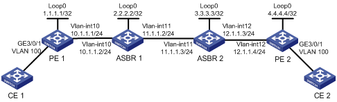
Implementing multi-AS VPN through multi-hop PW
Network requirements
Create a VPLS instance that supports P2P on ASBR 1 and ASBR 2, so as to set up a multi-hop PW between PE 1 and PE 2.
On PE 1 and PE 2, configure a service instance and bind it to the VPLS instance. The service instance matches the received packets that carry VLAN tag 100 on GigabitEthernet 3/0/1. The matched packets are forwarded by the VPLS instance.
Figure 14 Network diagram
Configuration procedure
1. Configure PE 1.
# Configure basic MPLS.
<Sysname> system-view
[Sysname] sysname PE1
[PE1] interface loopback 0
[PE1-LoopBack0] ip address 1.1.1.1 32
[PE1-LoopBack0] quit
[PE1] mpls lsr-id 1.1.1.1
[PE1] mpls
[PE1-mpls] quit
[PE1] mpls ldp
[PE1-mpls-ldp] quit
# Create a remote peer.
[PE1] mpls ldp remote-peer 1
[PE1-mpls-ldp-remote-1] remote-ip 2.2.2.2
[PE1-mpls-ldp-remote-1] quit
# Configure OSPF.
[PE1] ospf
[PE1-ospf-1] area 0
[PE1-ospf-1-area-0.0.0.0] network 1.1.1.1 0.0.0.0
[PE1-ospf-1-area-0.0.0.0] network 10.1.1.0 0.0.0.255
[PE1-ospf-1-area-0.0.0.0] quit
[PE1-ospf-1] quit
# Configure basic MPLS for the interface connecting ASBR 1.
[PE1] interface vlan-interface 10
[PE1-Vlan-interface10] ip address 10.1.1.1 24
[PE1-Vlan-interface10] mpls
[PE1-Vlan-interface10] mpls ldp
[PE1-Vlan-interface10] quit
# Enable L2VPN and MPLS L2VPN.
[PE1] l2vpn
[PE1-l2vpn] mpls l2vpn
[PE1-l2vpn] quit
# Create VPLS instance aaa that uses LDP signaling.
[PE1] vsi aaa static
[PE1-vsi-aaa] pwsignal ldp
[PE1-vsi-aaa-ldp] vsi-id 500
[PE1-vsi-aaa-ldp] peer 2.2.2.2
[PE1-vsi-aaa-ldp] quit
[PE1-vsi-aaa] quit
# On interface GigabitEthernet 3/0/1 connected to CE 1, create a service instance and bind the service instance with the VPLS instance aaa.
[PE1] interface GigabitEthernet 3/0/1
[PE1-GigabitEthernet3/0/1] service-instance 1000
[PE1-GigabitEthernet3/0/1-srv1000] encapsulation s-vid 100
[PE1-GigabitEthernet3/0/1-srv1000] xconnect vsi aaa
[PE1-GigabitEthernet3/0/1-srv1000] quit
2. Configure ASBR 1.
# Configure basic MPLS.
<Sysname> system-view
[Sysname] sysname ASBR1
[ASBR1] interface loopback 0
[ASBR1-LoopBack0] ip address 2.2.2.2 32
[ASBR1-LoopBack0] quit
[ASBR1] mpls lsr-id 2.2.2.2
[ASBR1] mpls
[ASBR1–mpls] quit
[ASBR1] mpls ldp
[ASBR1–mpls-ldp] quit
# Create remote LDP peers.
[ASBR1] mpls ldp remote-peer 1
[ASBR1-mpls-ldp-remote-1] remote-ip 3.3.3.3
[ASBR1-mpls-ldp-remote-1] quit
[ASBR1] mpls ldp remote-peer 2
[ASBR1-mpls-ldp-remote-2] remote-ip 1.1.1.1
[ASBR1-mpls-ldp-remote-2] quit
# Configure OSPF.
[ASBR1] ospf
[ASBR1-ospf-1] area 0
[ASBR1-ospf-1-area-0.0.0.0] network 2.2.2.2 0.0.0.0
[ASBR1-ospf-1-area-0.0.0.0] network 10.1.1.0 0.0.0.255
[ASBR1-ospf-1-area-0.0.0.0] quit
[ASBR1-ospf-1]quit
# Configure basic MPLS for the interface connecting PE 1.
[ASBR1] interface vlan-interface 10
[ASBR1-Vlan-interface10] ip address 10.1.1.2 24
[ASBR1-Vlan-interface10] mpls
[ASBR1-Vlan-interface10] mpls ldp
[ASBR1-Vlan-interface10] quit
# Configure basic MPLS for the interface connecting ASBR 2.
[ASBR1] interface vlan-interface 11
[ASBR1-Vlan-interface11] ip address 11.1.1.2 24
[ASBR1-Vlan-interface11] mpls
[ASBR1-Vlan-interface11] quit
# Enable L2VPN and MPLS L2VPN.
[ASBR1] l2vpn
[ASBR1-l2vpn] mpls l2vpn
[ASBR1-l2vpn] quit
# Configure a P2P-capable VPLS instance that uses LDP signaling.
[ASBR1] vsi aaa static p2p
[ASBR1-vsi-aaa] pwsignal ldp
[ASBR1-vsi-aaa-ldp] vsi-id 500
[ASBR1-vsi-aaa-ldp] peer 1.1.1.1 upe
[ASBR1-vsi-aaa-ldp] peer 3.3.3.3
[ASBR1-vsi-aaa-ldp] quit
[ASBR1-vsi-aaa] quit
# Configure BGP to advertise labeled unicast routes.
[ASBR1] bgp 100
[ASBR1-bgp] import-route direct
[ASBR1-bgp] peer 11.1.1.3 as-number 200
[ASBR1-bgp] peer 11.1.1.3 route-policy map export
[ASBR1-bgp] peer 11.1.1.3 label-route-capability
[ASBR1-bgp] quit
[ASBR1] route-policy map permit node 10
[ASBR1-route-policy] apply mpls-label
[ASBR1-route-policy] quit
3. Configure ASBR 2.
# Configure basic MPLS.
<Sysname> system-view
[Sysname] sysname ASBR2
[ASBR2] interface loopback 0
[ASBR2-LoopBack0] ip address 3.3.3.3 32
[ASBR2-LoopBack0] quit
[ASBR2] mpls lsr-id 3.3.3.3
[ASBR2] mpls
[ASBR2–mpls] quit
[ASBR2] mpls ldp
[ASBR2–mpls-ldp] quit
# Create remote LDP peers.
[ASBR2] mpls ldp remote-peer 2
[ASBR2-mpls-ldp-remote-2] remote-ip 2.2.2.2
[ASBR2-mpls-ldp-remote-2] quit
[ASBR2] mpls ldp remote-peer 3
[ASBR2-mpls-ldp-remote-3] remote-ip 4.4.4.4
[ASBR2-mpls-ldp-remote-3] quit
# Configure OSPF.
[ASBR2] ospf
[ASBR2-ospf-1] area 0
[ASBR2-ospf-1-area-0.0.0.0] network 3.3.3.3 0.0.0.0
[ASBR2-ospf-1-area-0.0.0.0] network 12.1.1.0 0.0.0.255
[ASBR2-ospf-1-area-0.0.0.0] quit
[ASBR2-ospf-1] quit
# Configure basic MPLS for the interface connecting ASBR 1.
[ASBR2] interface vlan-interface 11
[ASBR2-Vlan-interface11] ip address 11.1.1.3 24
[ASBR2-Vlan-interface11] mpls
[ASBR2-Vlan-interface11] quit
# Configure basic MPLS for the interface connecting PE 2.
[ASBR2] interface vlan-interface 12
[ASBR2-Vlan-interface12] ip address 12.1.1.3 24
[ASBR2-Vlan-interface12] mpls
[ASBR2-Vlan-interface12] mpls ldp
[ASBR2-Vlan-interface12] quit
# Enable L2VPN and MPLS L2VPN.
[ASBR2] l2vpn
[ASBR2-l2vpn] mpls l2vpn
[ASBR2-l2vpn] quit
# Configure a P2P-capable VPLS instance that uses LDP signaling.
[ASBR2] vsi aaa static p2p
[ASBR2-vsi-aaa] pwsignal ldp
[ASBR2-vsi-aaa-ldp] vsi-id 500
[ASBR2-vsi-aaa-ldp] peer 4.4.4.4 upe
[ASBR2-vsi-aaa-ldp] peer 2.2.2.2
[ASBR2-vsi-aaa-ldp] quit
[ASBR2-vsi-aaa] quit
# Configure BGP to advertise labeled unicast routes.
[ASBR2] bgp 200
[ASBR2-bgp] import-route direct
[ASBR2-bgp] peer 11.1.1.2 as-number 100
[ASBR2-bgp] peer 11.1.1.2 route-policy map export
[ASBR2-bgp] peer 11.1.1.2 label-route-capability
[ASBR2-bgp] quit
[ASBR2] route-policy map permit node 10
[ASBR2-route-policy] apply mpls-label
[ASBR2-route-policy] quit
4. Configure PE 2.
# Configure basic MPLS.
<Sysname> system-view
[Sysname] sysname PE2
[PE2] interface loopback 0
[PE2-LoopBack0] ip address 4.4.4.4 32
[PE2-LoopBack0] quit
[PE2] mpls lsr-id 4.4.4.4
[PE2] mpls
[PE2–mpls] quit
[PE2] mpls ldp
[PE2–mpls-ldp] quit
# Create a remote peer.
[PE2] mpls ldp remote-peer 1
[PE2-mpls-ldp-remote-1] remote-ip 3.3.3.3
[PE2-mpls-ldp-remote-1] quit
# Configure OSPF.
[PE2] ospf
[PE2-ospf-1] area 0
[PE2-ospf-1-area-0.0.0.0] network 4.4.4.4 0.0.0.0
[PE2-ospf-1-area-0.0.0.0] network 12.1.1.0 0.0.0.255
[PE2-ospf-1-area-0.0.0.0] quit
[PE2-ospf-1] quit
# Configure basic MPLS for the interface connecting ASBR 2.
[PE2] interface vlan-interface 12
[PE2-Vlan-interface12] ip address 12.1.1.4 24
[PE2-Vlan-interface12] mpls
[PE2-Vlan-interface12] mpls ldp
[PE2-Vlan-interface12] quit
# Enable L2VPN and MPLS L2VPN.
[PE2] l2vpn
[PE2-l2vpn] mpls l2vpn
[PE2-l2vpn] quit
# Configure a VPLS instance named aaa that uses LDP signaling.
[PE2] vsi aaa static
[PE2-vsi-aaa] pwsignal ldp
[PE2-vsi-aaa-ldp] vsi-id 500
[PE2-vsi-aaa-ldp] peer 3.3.3.3
[PE2-vsi-aaa-ldp] quit
[PE2-vsi-aaa] quit
# On interface GigabitEthernet 3/0/1 connected to CE 2, create a service instance and bind the service instance with the VPLS instance aaa.
[PE2] interface GigabitEthernet 3/0/1
[PE2-GigabitEthernet3/0/1] service-instance 1000
[PE2-GigabitEthernet3/0/1-srv1000] encapsulation s-vid 100
[PE2-GigabitEthernet3/0/1-srv1000] xconnect vsi aaa
[PE2-GigabitEthernet3/0/1-srv1000] quit
5. Verify the configuration.
Execute the display vpls connection command on each device. You can see that PWs are set up and in up state.
VPLS and MAC-in-MAC dual-stack support configuration example
Network requirements
As shown in Figure 15, establish a VPLS connection between PE and BEB-PE and a MAC-in-MAC connection between BEB-PE and BEB. To enable communication between the VPLS network and the PBBN, configure BEB-PE to support VPLS and MAC-in-MAC dual-stack.
· Create an LDP VPLS instance on the PE, with the name aaa, VSI ID 500, and peer PE’s address 2.2.2.9 (the loopback interface address of BEB-PE). On PE’s interface GigabitEthernet 3/0/1, which is connected to CE 1, create a service instance to match packets with outer VLAN tag 2, and then bind the service instance with LDP VPLS instance aaa. After the configuration, the PE forwards packets received from CE 1 that carry the VLAN tag of 2 through the VPLS connection between the PE and the BEB-PE.
· On the BEB, create a MAC-in-MAC instance aaa, and specify its I-SID as 100, uplink port as GigabitEthernet 3/0/1, and B-VLAN as VLAN 20. On BEB’s interface GigabitEthernet 3/0/2, which is connected to CE 2, create a service instance to match packets with the outer VLAN tag 2, and bind the service instance with the MAC-in-MAC instance aaa. After the configuration, BEB forwards packets received from CE 2 that carry the VLAN tag of 2 through GigabitEthernet 3/0/1, the port connecting BEB-PE.
· On the BEB-PE, create a VSI aaa that supports VPLS and MAC-in-MAC dual stack, and specify VSI aaa to use LDP as the PW signaling protocol, VSI ID as 500, peer address as 1.1.1.9 (PE’s loopback address), I-SID of MAC-in-MAC as 100, uplink port as GigabitEthernet 3/0/1, and B-VLAN as VLAN 20. After the configuration, BEB-PE establishes a VPLS connection with PE and a MAC-in-MAC connection with BEB, and forwards packets between PE and BEB, implementing communication between the VPLS network and the PBBN.
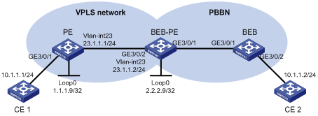
Configuration procedure
1. Configure PE.
# Configure an IP address for interface Loopback 0.
<Sysname> system-view
[Sysname] sysname PE
[PE] interface loopback 0
[PE-LoopBack0] ip address 1.1.1.9 32
[PE-LoopBack0] quit
# Configure the LSR-ID and enable MPLS globally.
[PE] mpls lsr-id 1.1.1.9
[PE] mpls
[PE-mpls] quit
# Enable L2VPN and MPLS L2VPN.
[PE] l2vpn
[PE-l2vpn] mpls l2vpn
[PE-l2vpn] quit
# Enable LDP globally.
[PE] mpls ldp
[PE-mpls-ldp] quit
# Configure VLAN-interface 23, the interface connecting BEB-PE, and enable LDP on the interface.
[PE] interface vlan-interface 23
[PE-Vlan-interface23] ip address 23.1.1.1 24
[PE-Vlan-interface23] mpls
[PE-Vlan-interface23] mpls ldp
[PE-Vlan-interface23] quit
# Create a remote peer.
[PE] mpls ldp remote-peer 1
[PE-mpls-ldp-remote-1] remote-ip 2.2.2.9
[PE-mpls-ldp-remote-1] quit
# Configure OSPF.
[PE] ospf
[PE-ospf-1] area 0
[PE-ospf-1-area-0.0.0.0] network 23.1.1.1 0.0.0.255
[PE-ospf-1-area-0.0.0.0] network 1.1.1.9 0.0.0.0
[PE-ospf-1-area-0.0.0.0] quit
[PE-ospf-1] quit
# Create a VSI named aaa, use LDP as the PW signaling, set VSI ID to 500, and specify the peer address as 2.2.2.9.
[PE] vsi aaa static
[PE-vsi-aaa] pwsignal ldp
[PE-vsi-aaa-ldp] vsi-id 500
[PE-vsi-aaa-ldp] peer 2.2.2.9
[PE-vsi-aaa-ldp] quit
[PE-vsi-aaa] quit
# Configure GigabitEthernet 3/0/1, the interface connecting CE 1, as a trunk port that allows packets of VLAN 2 to pass.
[PE] interface GigabitEthernet 3/0/1
[PE-GigabitEthernet3/0/1] port link-type trunk
[PE-GigabitEthernet3/0/1] port trunk permit vlan 2
# Create a service instance on GigabitEthernet 3/0/1, configure the service instance to match packets with the outer VLAN tag of 2, and bind the service instance with VSI aaa.
[PE-GigabitEthernet3/0/1] service-instance 1
[PE-GigabitEthernet3/0/1-srv1] encapsulation s-vid 2
[PE-GigabitEthernet3/0/1-srv1] xconnect vsi aaa
[PE-GigabitEthernet3/0/1-srv1] quit
[PE-GigabitEthernet3/0/1] quit
2. Configure BEB-PE.
# Configure an IP address for interface Loopback 0.
<Sysname> system-view
[Sysname] sysname BEB-PE
[BEB-PE] interface loopback 0
[BEB-PE-LoopBack0] ip address 2.2.2.9 32
[BEB-PE-LoopBack0] quit
# Configure the LSR-ID and enable MPLS globally.
[BEB-PE] mpls lsr-id 2.2.2.9
[BEB-PE] mpls
[BEB-PE-mpls] quit
# Enable L2VPN and MPLS L2VPN.
[BEB-PE] l2vpn
[BEB-PE-l2vpn] mpls l2vpn
[BEB-PE-l2vpn] quit
# Enable LDP globally.
[BEB-PE] mpls ldp
[BEB-PE-mpls-ldp] quit
# Configure VLAN-interface 23, the interface connecting PE, and enable LDP on the interface.
[BEB-PE] interface vlan-interface 23
[BEB-PE-Vlan-interface23] ip address 23.1.1.2 24
[BEB-PE-Vlan-interface23] mpls
[BEB-PE-Vlan-interface23] mpls ldp
[BEB-PE-Vlan-interface23] quit
# Create a remote peer.
[BEB-PE] mpls ldp remote-peer 1
[BEB-PE-mpls-ldp-remote-1] remote-ip 1.1.1.9
[BEB-PE-mpls-ldp-remote-1] quit
# Configure OSPF.
[BEB-PE] ospf
[BEB-PE-ospf-1] area 0
[BEB-PE-ospf-1-area-0.0.0.0] network 23.1.1.2 0.0.0.255
[BEB-PE-ospf-1-area-0.0.0.0] network 2.2.2.9 0.0.0.0
[BEB-PE-ospf-1-area-0.0.0.0] quit
[BEB-PE-ospf-1] quit
# Configure a VSI named aaa, which supports both VPLS and MAC-in-MAC and uses the static peer discovery mechanism and the I-SID of 100.
[BEB-PE] vsi aaa static minm i-sid 100
# Configure the VSI to use LDP for PW signaling, set the VSI ID to 500, and specify the peer address as 1.1.1.9.
[BEB-PE-vsi-aaa] pwsignal ldp
[BEB-PE-vsi-aaa-ldp] vsi-id 500
[BEB-PE-vsi-aaa-ldp] peer 1.1.1.9
[BEB-PE-vsi-aaa-ldp] quit
# Specify VLAN 20 as the B-VLAN of VSI aaa.
[BEB-PE-vsi-aaa] minm bvlan 20
[BEB-PE-vsi-aaa] quit
# Configure port GigabitEthernet 3/0/1 as the uplink port of VSI aaa, and as a trunk port that permits packets of VLAN 20 to pass.
BEB-PE] interface GigabitEthernet 3/0/1
[BEB-PE-GigabitEthernet3/0/1] port link-type trunk
[BEB-PE-GigabitEthernet3/0/1] port trunk permit vlan 20
[BEB-PE-GigabitEthernet3/0/1] minm uplink vsi aaa
[BEB-PE-GigabitEthernet3/0/1] quit
3. Configure BEB.
# Enable L2VPN.
<Sysname> system-view
[Sysname] sysname BEB
[BEB] l2vpn
[BEB-l2vpn] quit
# Create a VSI aaa that supports MAC-in-MAC and uses the I-SID of 100.
[BEB] vsi aaa minm i-sid 100
# Specify VLAN 20 as the B-VLAN of VSI aaa.
[BEB-vsi-aaa] minm bvlan 20
[BEB-vsi-aaa] quit
# Configure GigabitEthernet 3/0/1, the uplink port for MAC-in-MAC, as a trunk port that permits packets of VLAN 20 to pass, and specify the port as the uplink port of VSI aaa.
[BEB] interface GigabitEthernet 3/0/1
[BEB-GigabitEthernet3/0/1] port link-type trunk
[BEB-GigabitEthernet3/0/1] port trunk permit vlan 20
[BEB-GigabitEthernet3/0/1] minm uplink vsi aaa
[BEB-GigabitEthernet3/0/1] quit
# Configure GigabitEthernet 3/0/2, the downlink port for MAC-in-MAC, as a trunk port that permits packets of VLAN 2 to pass, create service instance 1 on the port, configure the service instance to match packets with the outer VLAN tag of 2, and bind the service instance with VSI aaa.
[BEB] interface GigabitEthernet 3/0/2
[BEB-GigabitEthernet 3/0/2] port link-type trunk
[BEB-GigabitEthernet 3/0/2] port trunk permit vlan 2
[BEB-GigabitEthernet 3/0/2] service-instance 1
[BEB-GigabitEthernet 3/0/2-srv2] encapsulation s-vid 2
[BEB-GigabitEthernet 3/0/2-srv2] xconnect vsi aaa
[BEB-GigabitEthernet 3/0/2-srv2] quit
[BEB-GigabitEthernet 3/0/2] quit
4. Verify the configuration.
# Execute the display vpls connection command on BEB-PE. You can see that a PW link is set up between BEB-PE and PE, and is in the up state.
[BEB-PE] display vpls connection vsi aaa
Total 1 connection(s),
connection(s): 1 up, 0 block, 0 down, 1 ldp, 0 bgp
VSI Name: aaa Signaling: ldp
VsiID VsiType PeerAddr InLabel OutLabel LinkID VCState
500 vlan 1.1.1.9 1024 1024 1 up
# Execute the display minm connection command on BEB-PE. You can see the MAC-in-MAC uplink information of the VSI aaa. The information means that BEB-PE has learnt the B-MAC information from BEB, its peer device.
[BEB-PE] display minm connection vsi aaa
VSIID LinkID BMAC BVLAN Interface Name State AGING TIME(s)
500 1 000F-E200-0001 VLAN 20 GigabitEthernet3/0/1 Learned AGING
# Ping CE 2 from CE 1. The ping operation succeeds.
<CE1> ping 10.1.1.2
PING 10.1.1.2: 56 data bytes, press CTRL_C to break
Reply from 10.1.1.2: bytes=56 Sequence=1 ttl=255 time=180 ms
Reply from 10.1.1.2: bytes=56 Sequence=2 ttl=255 time=60 ms
Reply from 10.1.1.2: bytes=56 Sequence=3 ttl=255 time=10 ms
Reply from 10.1.1.2: bytes=56 Sequence=4 ttl=255 time=70 ms
Reply from 10.1.1.2: bytes=56 Sequence=5 ttl=255 time=60 ms
--- 10.1.1.2 ping statistics ---
5 packet(s) transmitted
5 packet(s) received
0.00% packet loss
round-trip min/avg/max = 10/76/180 ms
Troubleshooting VPLS
Symptom
The VPLS PW is not up.
Analysis
· The public network LSP tunnel is not established.
· The extended session is not working normally.
· A private network interface is not bound with the corresponding VPLS instance or the private network interface is not up.
· The AC port at the private network side is not up.
· Negotiation of VPLS parameters, such as PW ID, MTU, and transport mode, is failed on the two peers.
Solution
· Check the routing tables of the PEs to see whether a route is available between the two PEs. Check whether each device can ping the loopback interface of the peer and whether the LDP session is normal.
· Check whether any extended session configuration command is missing at either side.
· View the private interface status by using the display interface command. Make sure the private interface is up.
· View the current configuration by using the display current-configuration command. Make sure that the two peers have the same PW ID and transport mode.
