- Table of Contents
- Related Documents
-
| Title | Size | Download |
|---|---|---|
| 05-IP Addressing Configuration | 92.21 KB |
Table of Contents
Assigning an IP Address to an Interface
IP Addressing Configuration Example
Displaying and Maintaining IP Addressing
l Support of the H3C WA series WLAN access points (APs) for features may vary by AP model. For more information, see Feature Matrix.
l The interface types and the number of interfaces vary by AP model.
l The term AP in this document refers to common APs, wireless bridges, and mesh APs.
l The models listed in this document are not applicable to all regions. Please consult your local sales office for the models applicable to your region.
This chapter includes these sections:
l Displaying and Maintaining IP Addressing
IP Addressing Overview
IP Address Classes
IP addressing uses a 32-bit address to identify each host on a network. An example is 00001010000000010000000100000001 in binary. To make IP addresses in 32-bit form easier to read, they are written in dotted decimal notation, each being four octets in length, for example, 10.1.1.1 for the address just mentioned.
Each IP address breaks down into two parts:
l Net ID: Identifies a network. The first several bits of a net ID are known as class fields or class bits to identify the class of an IP address.
l Host ID: Identifies a host on a network.
IP addresses are divided into five classes, as shown in the following figure (in which the blue parts represent the address class).
Figure 1-1 IP address classes
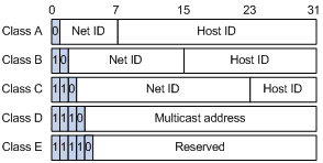
Table 1-1 describes the address ranges of these five classes. Currently, the first three classes of IP addresses are mainly used.
Table 1-1 IP address classes and ranges
|
Class |
Address range |
Description |
|
A |
0.0.0.0 to 127.255.255.255 |
The IP address 0.0.0.0 is used by a host at bootstrap for temporary communication. This address is never a valid destination address. Addresses starting with 127 are reserved for loopback test. Packets destined to these addresses are processed locally as input packets rather than sent to the link. |
|
B |
128.0.0.0 to 191.255.255.255 |
–– |
|
C |
192.0.0.0 to 223.255.255.255 |
–– |
|
D |
224.0.0.0 to 239.255.255.255 |
Multicast address. |
|
E |
240.0.0.0 to 255.255.255.255 |
Reserved for future use except for the broadcast address 255.255.255.255. |
Special Case IP Addresses
The following IP addresses are for special use, and they cannot be used as host IP addresses:
l IP address with an all-zero net ID: Identifies a host on the local network. For example, IP address 0.0.0.16 indicates the host with a host ID of 16 on the local network.
l IP address with an all-zero host ID: Identifies a network.
l IP address with an all-one host ID: Identifies a directed broadcast address. For example, a packet with the destination address of 192.168.1.255 will be broadcasted to all the hosts on the network 192.168.1.0.
Subnetting and Masking
Subnetting was developed to address the risk of IP address exhaustion resulting from fast expansion of the Internet. The idea is to break a network down into smaller networks called subnets by using some bits of the host-id to create a subnet-id. To identify the boundary between the host-id and the combination of net-id and subnet-id, masking is used. (When subnetting is not adopted, a mask identifies the boundary between the net-id and the host-id.)
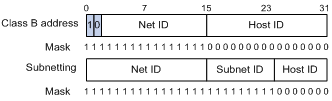
Each subnet mask comprises 32 bits related to the corresponding bits in an IP address. In a subnet mask, the part containing consecutive ones identifies the combination of net-id and subnet-id whereas the part containing consecutive zeros identifies the host-id.
Figure 1-2 shows how a Class B network is subnetted.
Figure 1-2 Subnet a Class B network
While allowing you to create multiple logical networks within a single Class A, B, or C network, subnetting is transparent to the rest of the Internet. All these networks still appear as one. As subnetting adds an additional level, subnet-id, to the two-level hierarchy with IP addressing, IP routing now involves three steps: delivery to the site, delivery to the subnet, and delivery to the host.
In the absence of subnetting, some special addresses such as the addresses with the net-id of all zeros and the addresses with the host-id of all ones, are not assignable to hosts. The same is true for subnetting. When designing your network, you should note that subnetting is somewhat a tradeoff between subnets and accommodated hosts. For example, a Class B network can accommodate 65,534 (216 – 2. Of the two deducted Class B addresses, one with an all-one host-id is the broadcast address and the other with an all-zero host-id is the network address) hosts before being subnetted. After you break it down into 512 (29) subnets by using the first 9 bits of the host-id for the subnet, you have only 7 bits for the host-id and thus have only 126 (27 – 2) hosts in each subnet. The maximum number of hosts is thus 64,512 (512 × 126), 1022 less after the network is subnetted.
Class A, B, and C networks, before being subnetted, use these default masks (also called natural masks): 255.0.0.0, 255.255.0.0, and 255.255.255.0 respectively.
Configuring IP Addresses
Besides directly assigning an IP address to an interface, you may configure the interface to obtain one through DHCP. If you change the way an interface obtains an IP address, from manual assignment to DHCP for example, the IP address obtained through DHCP will overwrite the old one manually assigned.
![]()
This chapter only covers how to assign an IP address manually. For how to obtain an IP address through or DHCP, see DHCP in the Layer 3 – IP Services Configuration Guide. For how to obtain an IP address through PPP address negotiation, see PPP in the Layer 2 – WAN Configuration Guide.
Assigning an IP Address to an Interface
You may assign an interface multiple IP addresses, one primary and multiple secondaries.
Generally, you only need to assign the primary address to an interface. In some cases, you need to assign secondary IP addresses to the interface. For example, if the interface connects to two subnets, to enable the AP to communicate with all hosts on the LAN, you need to assign a primary IP address and a secondary IP address to the interface.
Follow these steps to assign an IP address to an interface:
|
To do… |
Use the command… |
Remarks |
|
Enter system view |
system-view |
–– |
|
Enter interface view |
interface interface-type interface-number |
–– |
|
Assign an IP address to the interface |
ip address ip-address { mask | mask-length } [ sub ] |
Required No IP address is assigned by default. |
![]()
l The primary IP address you assigned to the interface can overwrite the old one if there is any.
l You cannot assign secondary IP addresses to an interface that has DHCP or IP unnumbered configured.
l The primary and secondary IP addresses you assign to the interface can be located on the same network segment. However, this should not violate the rule that the IP addresses of different interfaces must reside on different network segments.
IP Addressing Configuration Example
Network requirements
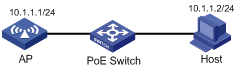
As shown in Figure 1-3, the IP address of VLAN-interface 1 on the AP is 10.1.1.1/24. The IP address of the host is 10.1.1.2/24. The AP and host are connected to the PoE switch.
On the host, telnet to the PoE-powered AP to manage the AP remotely.
Figure 1-3 Network diagram for IP addressing configuration
Configuration procedure
# Assign an IP address to VLAN-interface 1.
<AP> system-view
[AP] interface vlan-interface 1
[AP-Vlan-interface1] ip address 10.1.1.1 24
[AP-Vlan-interface1] quit
# Configure Telnet.
# Set the authentication mode to password.
[AP] user-interface vty 0 4
[AP-ui-vty0-4] authentication-mode password
# Set the authentication password to admin in plain text.
[AP-ui-vty0-4] set authentication password simple admin
# Set the user level to 3.
[AP-ui-vty0-4] user privilege level 3
[AP-ui-vty0-4] quit
# Telnet to the AP from the host.

Displaying and Maintaining IP Addressing
|
To do… |
Use the command… |
Remarks |
|
Display information about a specified or all Layer 3 interfaces |
display ip interface [ interface-type interface-number ] |
Available in any view |
|
Display brief information about a specified or all Layer 3 interfaces |
display ip interface brief [ interface-type [ interface-number ] ] |
Available in any view |
